Embed Size (px)
Citation preview

GeneralSpecifications
UP55AProgram Controller
Yokogawa Electric Corporation2-9-32, Nakacho, Musashino-shi, Tokyo, 180-8750 JapanTel.: 81-422-52-7179 Fax.: 81-422-52-6619
GS 05P02C41-01EN
GS 05P02C41-01EN©Copyright Aug. 2010
7th Edition Mar.14,2016
n OverviewThe UP55A program controller employs an easy-to-read, 14-segment large color LCD display, along with navigation keys, thus greatly increasing the monitoring and operating capabilities. A ladder sequence function is included as standard. The short depth of the controller helps save instrument panel space. The UP55A also support open networks such as Ethernet communication.
n Features・ Equipped with a large-capacity program
setting function that can store 99 program patterns and 600 program segments. It can be used in a wide variety of heating/cooling control applications (on models with the /AP option).
• A 14-segment, active (PV display color changing function) color LCD display is employed.
Twofive-digit,high-resolutiondisplaysarepossible. Alphabet letters can be displayed in an easy-to-read
manner. The guide display shows parameter names.• Easy to operate Navigation keys (SET/ENTER and Up/Down/Left/
Right arrow keys) are employed to facilitate making settings.
• 65 mm depth The small depth enables the mounting in a thin and
small instrumented panel.• Ladder sequence function is included as standard. This function allows for creating a simple sequence
control. Dedicated LL50A Parameter Setting Software (sold separately) allows for performing programming using a ladder language.
• Various built-in open network functions such as Ethernet are available.
Easy connection with various vendors’ PLCs is possible.
• Quick setting function Setting only the minimum necessary parameters for
operation is possible. (For single-loop control only)• Equipped with a multitude of functions Universal I/O and eight control modes (cascade
control, etc) are included as standard. PID control, heating/cooling control, feed forward control, etc. are available.
• LL50A Parameter Setting Software (sold separately) The parameters and ladder programs of UTAdvanced
digital indicating controller can be built from a PC using this software. It makes data management even easier.
• Dust-proof and drip-proof IP66 (for front panel) (Not applicable to side-by-side
close mounting.) NEMA4 (Hose-down test only)
nFunctionalSpecificationsProgram Pattern Functions The program setting function increases or decreases
the value of a target setpoint (SP) according to a given program pattern that varies with time. The controller stores two or more program patterns and the operator can switch between them according to the operating status. Each program pattern consists of multiple line segments (program segments). The operator sets the time interval of each program segment using the segment time or slope. The operator can also set such instructions as the number of repeats, start/stop, and status output (event output) for a given program pattern.
Number of Program pattern Max. 30 (Max. 99 with /AP option)Number of program segment per pattern Max. 99Total number of program segments
Max. 300 (Max. 600 with /AP option)(Total of all program patterns)
Segment time 0.00 to 999.59 (hour.minute or minute.second)
Number of PV event 8
PV event type
PV (measured value) high/low limitSP (setpoint) high/low limitDeviation high/low limitDeviation high and low limitsDeviation within high and low limitsTarget SP high/low limitTarget SP deviation high/low limitTarget SP deviation high and low limitsTarget SP deviation within high and low limitsControl output high/low limit alarmCooling control output high/low limit alarm
Number of Time event 16
Time of time event 0.01 to 999.59 (hour.minute or minute.second)
Number ofrepeat cycle 0 to 999, CONT (limitless number of times)
Wait operation5 groupsCan be set the upper-side wait zone and the lower zone for program setpoint.
Fast-forwarding ofprogram operation
1: Normal, 2: Twice, 5: Five times, 10: Ten times, 20: Twenty timesUse this function when checking the program pattern setting. Only Time of Segment and Time event can be faster.
Functional
Enhancement
2
All Rights Reserved. Copyright © 2010, Yokogawa Electric Corporation GS 05P02C41-01EN Mar.14,2016-00
Synchronized program operation
If the progress of the operation of one unit is faster, the program operation can be forcibly stopped by digital input when switching between segments.
Program pattern link Available
Program pattern editAddition and deleting of program segment can be available. Copy and deletion of program pattern can also be available.
n Control Computation FunctionControlSpecifications(1) Control Mode Control functions of the controller can be set as
control modes.
Control mode FunctionSGL Single-loop control
CAS1 Cascade primary-loop controlCAS Cascade control
PVSW Loop control with PV switching
PVSEL Loop control with PV auto-selector (Max./Min./Ave./Diff)
*1: Remote auxiliary analog input is required.
(2) Control period Selectable from 100 ms, and 200 ms
Model andsuffixcode
(See themodel code)
Numberof analog
inputpoints
Numberof analog
outputpoints (*1)
Numberof contact
inputpoints (*2)
Number ofcontactoutput
points (*3)
UP55A-x0x 1 1 8 8-x1x 2 1 9 (8) 8-x2x 1 1 8 8-x3x 1 1 8 18-x4x 4 1 6 (5) 3
*1: Excluding control output*2: The numbers in parentheses show the numbers
of points in each model with RSP direct input.(/DR option)
*3: Excluding control output relays
ControlComputationSpecifications(1) Combination of types of control and control
modes
Types of control Control modeSGL CAS1 CAS PVSW PVSEL
PID control √ √ √ √ √ON/OFF control (*1) √ N/A N/A √ √Heating and cooling control (*2) √ N/A √ √ √
√:Available,N/A:NotAvailable*1: Not selectable for Position proportional type*2: Selectable for heating and cooling control
(2) Control Computation Function(a) The number of PID parameter groups Eight sets of PID parameters can be set. For cascade
control, respectively, eight sets can be set for main (primary side) and slave (secondary side).
(b) Selecting the PID parameter group The following PID parameter groups can be selected. • Segment PID • Measured input zone PID • Target setpoint zone PID • Reached target setpoint zone PID • Local PID • Reference deviation(c) Auto-tuning • Tuning results can be selected from two options,
Normal or Stable. • Tuning output limit can be set. (It cannot be used in
heating/cooling control.)(d) “Super” function: Overshoot-suppressing function(e) “Super 2” function: Hunting-suppressing function(f) RESET preset output function(g) Input ERROR preset output function(h) MANUAL preset output function(3) Operation Mode Switching
Operation mode switching
Start of program operation (PROG)Stop of program operation (RESET)Start of local-mode operation (LOCAL)Start of remote-mode operation (REM)Pause/cancel release of program operation (HOLD)Advance of segment (ADV)Automatic (AUTO)/Manual (MAN) switchingLocal (LSP)/CAS switching when in cascade control
(4) Control Parameter Setting RangeProportional band 0.1 to 999.9%Integral time 1 to 6000 sec. or OFF (using manual
reset)Derivative time 1 to 6000 sec. or OFFON/OFF control hysteresis (one or two hysteresis points)
0.0 to 100.0% of measured input range width
Preset output value -5.0 to 105.0% (however, 0 mA or less cannot be output)
High/low output limiter -5.0 to 105.0%Low limit setpoint < high limit setpoint
Tight shut functionWhen manual control is carried out with 4 to 20 mA output, control output can be reduced to about 0 mA.
Rate-of-change limiter of output 0.1 to 100.0%/sec., OFF
Output dead bandFor heating and cooling control: -100.0 to 50.0%For position proportional control: 1.0 to 10.0%
Alarm Functions• Types of Alarm
Measured value alarmDeviation alarmRate-of-change alarm
PV (measured value) high/low limit alarmDeviation high/low limit alarmDeviation high and low limits alarmDeviation within high and low limits alarmAnalog input PV high/low limit alarmAnalog input RSP high/low limit alarmAuxiliary analog input high/low limit alarmFeedback input high/low limit alarmPV rate-of-change alarm
Setpoint alarm
SP (setpoint) high/low limit alarmTarget SP high/low limit alarmTarget SP deviation high/low limit alarmTarget SP deviation high and low limits alarmTarget SP deviation within high and low limits alarm
Output alarm Control output high/low limit alarmCooling control output high/low limit alarm
Other alarmsHeater disconnection alarm (for /HA option)Self-diagnosis alarmFAIL

3
All Rights Reserved. Copyright © 2010, Yokogawa Electric Corporation GS 05P02C41-01EN Mar.14,2016-00
• Alarm Functions
Alarm outputaction
Alarm stand-by actionAlarm latch (forced reset) functionAlarm hysteresisAlarm ON/OFF delay timer
Number of alarm settings 8 (per loop)Number of alarm output points
Upto9(differsbymodelcode)
Contact I/O Function This function allows for allocating the input error
condition, operation condition, alarm condition or other conditions to the contact input and contact output.
Contact input
Switch to PROG (Start of program operation)Switch to RESET (Stop of program operation)Switch to LOCAL (LSP) (Start of local-mode operation)Switch to REMOTEPROG/RESET SwitchPROG/LOCAL (LSP) SwitchPROG/HOLD SwitchSwitch to HOLD (Start of hold-mode operation)Advance of segmentWait ON/OFF switchAUTO/MAN switchLOCAL (LSP)/CAS switchAuto-tuning START/STOP switchOutput tracking switchingTwo-input switchingLatch releaseLCD backlight ON/OFF switchPV red/white switchMessage interrupt displays 1 through 4Program pattern number selectionPID number selectionManual preset output number selection
Contact output
PV event, Time event, AlarmLoop 2 alarm (for cascade control)Status output
Ladder Sequence Function(1) Number of I/O PointsNumber of digital input points Up to 9Number of digital output points Up to 18
This is limited by the number of contact I/O signal points. (See the model code.)
(2) Types of InstructionNumber of instructions Remark
Number of basicinstruction types 13 Load, AND, OR, Timer,
Counter, etc.Number of applicationinstruction types
73Comparison, reverse, addition/subtraction/multiplication/division, logic operation, high/low limiter, etc.
(3) Sequence DeviceTypes of device Number of points
Digital I/O Input relay 9 (max.)Output relay 18 (max.)
Internal deviceM relay (bit data) 256DAT register (data) 28P register (parameter) 10K register (constant) 30
Special device Special relay (bit data) 12
Process data and process relay can be used besides the above-mentioned.
(4) Program capacityMax. Program capacity: 500 steps *
*: Availablenumberofstepsdiffersaccordingtotheparameters, using command and control period.
(5) Ladder computation period Ladder computation period is the same as control
period.
4
All Rights Reserved. Copyright © 2010, Yokogawa Electric Corporation GS 05P02C41-01EN Mar.14,2016-00
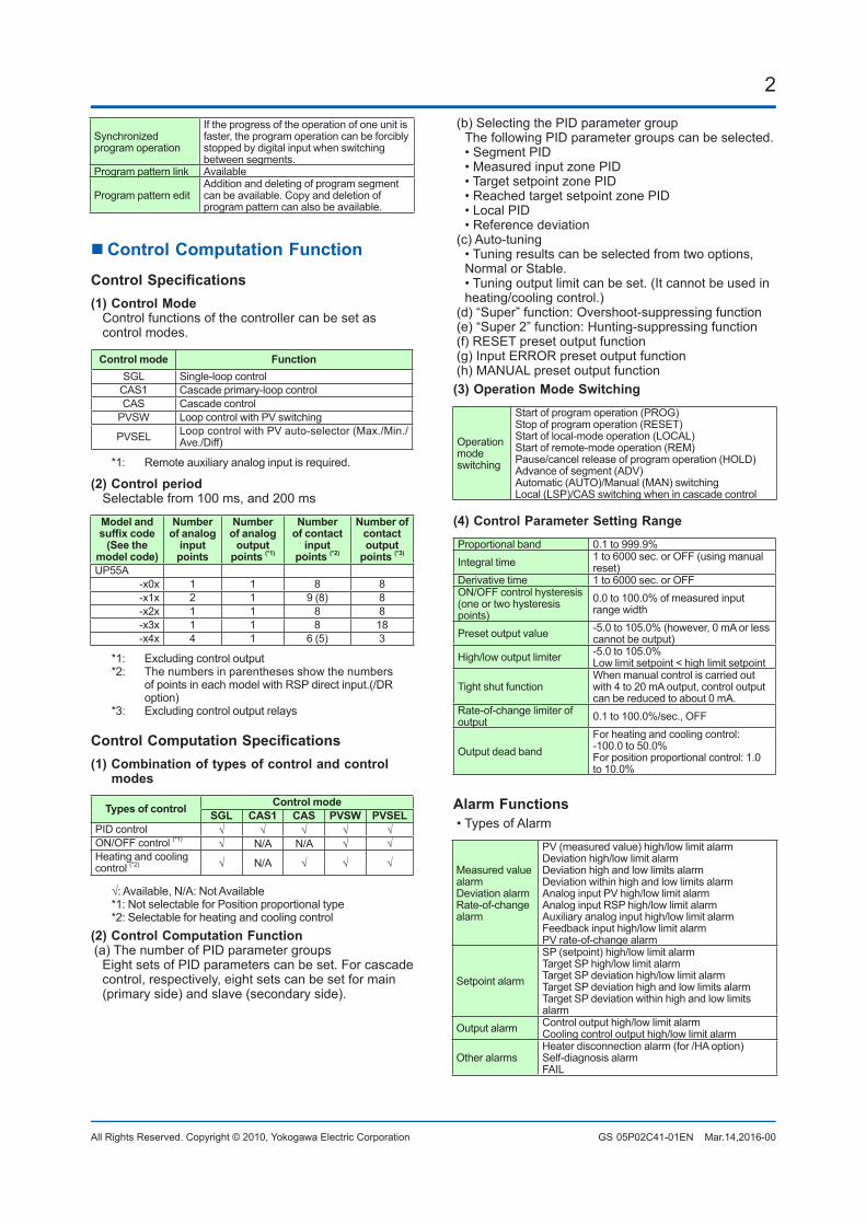
Communication Function
Function Method Interface Targets Maxconnection CommunicationData
Modbus/TCP A standard industry protocol allowing communications between the controller anddevices such as PCs, PLCs, and DCSs.
Server Ethernet PLC and others 2 connections(*3) PV, ALM etcGateway Ethernet
+ RS-485RS-485: UT75A/UT55A/UT52A/UT35A/UT32A/UP55A/UP35A/UM33A (*1)
31 units
Modbus(RTU/ASCII)
Slave RS-485 PLC and others, UT55A/UT75A/UT52A/UT35A/UT32A/UP55A/UP35A/UP32A/UM33A (*1)
31 units
PROFIBUS-DP Used for communicationbetween PLCs andremote I/O, enabling highspeeddata transmission.
Slave RS-485 PLC and others Number of nodes: 126
Modbus masterfunction
RS-485 UT75A/UT55A/UT52A/UT35A/UT32A/UP55A/UP35A
31 Units(Main Controller is included.)
CC-Link Slave RS-485 PLC and others Number of nodes: 42 (Remote device)
Modbus masterfunction
RS-485 UT75A/UT55A/UT52A/UT35A/UT32A/UP55A/UP35A/UP32A/UM33A
31 Units(Main Controller is included.)
DeviceNet Slave RS-485 PLC and others Number of nodes: 64Modbus masterfunction
RS-485 UT75A/UT55A/UT52A/UT35A/UT32A/UP55A/UP35A
31 Units(Main Controller is included.)
Peer to peer A protocol allowing multiple controllers to send and receive data between one another. The Ladder Program is used.
Multi-drop RS-485(2 wireonly)
UT75A/UT55A/UT52A/UT35A/UT32A/UP55A/UP35A/UP32A
Read/Write: 4 unitsRead only : 28 units
CoordinatedCommunication
A protocol to coordinate the operation of two or more instruments controlling the same process.
Master/Slave
RS-485 UT75A/UT55A/UT52A/UT35A/UT32A/UP55A/UP35A/UP32A (*2)
Master : 1 unitSlave : 31 units
PC link The proprietary Yokogawa protocol allowingcommunications to PCs, PLCs and touch panels.
Slave RS-485 UT75A/UT55A/UT52A/UT35A/UT32A/UP55A/UP35A/UP32A/UM33A (*2)
31 units
Ladder A protocol to communicate to PLCs.
*1: UT digital indicating controller, Signal conditioner JUXTA, Power monitor POWERCERT can be connected.*2: UT digital indication controllers can be connected.*3: Maximum number of transactions: 1 (per a connection)
Physical InterfaceEthernet Standard : IEEE802.3 (10BASE-T, 100BASE-TX) Max segment length : 100 m Max.ConnectingConfiguration:CascadeMax.4level(10BASE-T),Max.2level(100BASE-TX)RS-485 Standard: EIA RS-485 Communication method: Two-wire harf-duplex or four-wire harf-duplex, start-stop synchronization, and
non-procedural Baud rate: 600,1200,2400,4800,9600,19200 or 38400 bps (*3)
Peertopeercommunicationisfixedat19200bps Maximum communication distance: 1200 m Terminatingresistor:220Ω(External) *3: “38400 bps” is available only for UP55A (Type 3 code = 1)PROFIBUS-DP Standard : Field bus (IEC61158) Corresponding version : DP V0 Baud rate : 9.6k, 19.2k, 45.45k, 93.75k, 187.5k, 0.5M, 1.5M, 3M, 6M, 12M, AUTO (*4)
Communication distance : 1200m (9.6k to 93.75k), 1000m (187.5k), 400m (0.5M), 200m (1.5M), 100m (3M to 12M) *4: AUTO automatically sets the baud rate to that of the host controller (PROFIBUS-DP master).CC-Link Supported version : Remote device (Ver.1.10, Ver.2.00) Baud rate : 156k, 625k, 2.5M, 5M, 10M bps Transmission distance : 1.2km (156k bps), 600m (625k bps), 200m (2.5M bps), 150m (5M bps), 100m (10M bps) When using optical repeater : 7.6 km (156k) to 4.3 km (10M)DeviceNet Standard : Field bus (IEC61158) Baud rate 125k, 250k, 500k bps Transmission distance 500m (125k bps), 250m (250k bps), 100m (500k bps)
5
All Rights Reserved. Copyright © 2010, Yokogawa Electric Corporation GS 05P02C41-01EN Mar.14,2016-00
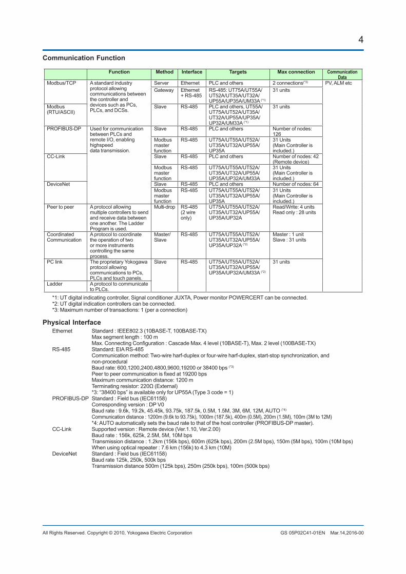
nHardwareSpecificationsDisplaySpecifications• PV display: 5-digit, 14-segment active color LCD (white/red) Character height: 21.5 mm• Data display: 5-digit, 11-segment color LCD (orange)• Bar graph display: 12-segment color LCD (orange)
(1) PV display(9) Deviation indicator
(2) Group display(Pattern number)
(10) Status indicator
(11) Security indicator
(12) Ladder operation indicator
(13) Loop 2 indicator
(4) Data display
(2) + (3) + (4) : Setpoint display
(3) Symbol display
(5) Bar-graph display (Event, alarm)(6) Event indicator
(7) Key navigation indicator
(8) Parameter display level indicator
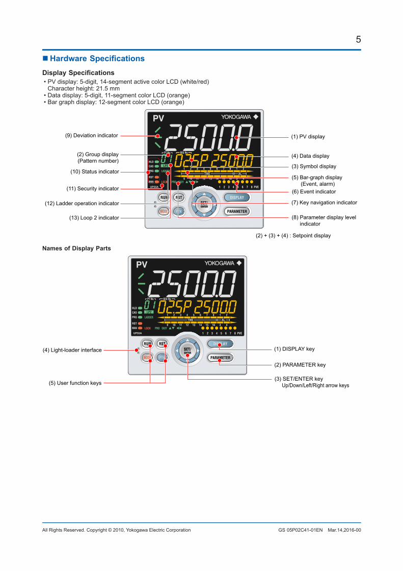
Names of Display Parts
(4) Light-loader interface
(5) User function keys
(1) DISPLAY key
(2) PARAMETER key
(3) SET/ENTER key Up/Down/Left/Right arrow keys

6
All Rights Reserved. Copyright © 2010, Yokogawa Electric Corporation GS 05P02C41-01EN Mar.14,2016-00
UniversalInputSpecifications• Number of inputs: 1• Input type, instrument range, and measurement accuracy: See the table below.
Input Type Instrument Range (°C) Instrument Range (°F) Accuracy
Thermo-couple
K-270.0 to 1370.0°C -450.0 to 2500.0°F ±0.1% of instrument range ±1 digit for 0°C or more
±0.2% of instrument range ±1 digit for less than 0°C±2% of instrument range ±1 digit for less than -200.0°C of thermocouple K ±1% of instrument range ±1 digit for less than -200.0°C of thermocouple T
-270.0 to 1000.0°C -450.0 to 2300.0°F-270.0 to 500.0°C -200.0 to 1000.0°F
J -200.0 to 1200.0°C -300.0 to 2300.0°FT -270.0 to 400.0°C -450.0 to 750.0°F
0.0 to 400.0°C -200.0 to 750.0°F
B 0.0 to 1800.0°C 32 to 3300°F±0.15% of instrument range ±1 digit for 400°C or more±5% of instrument range ±1 digit for less than 400°C
S 0.0 to 1700.0°C 32 to 3100°F ±0.15% of instrument range ±1 digitR 0.0 to 1700.0°C 32 to 3100°FN -200.0 to 1300.0°C -300.0 to 2400.0°F ±0.1% of instrument range ±1 digit
±0.25% of instrument range ±1 digit for less than 0°CE -270.0 to 1000.0°C -450.0 to 1800.0°F ±0.1% of instrument range ±1 digit for 0°C or more
±0.2% of instrument range ±1 digit for less than 0°C±1.5% of instrument range ±1 digit for less than -200.0°C of thermocouple E.
L -200.0 to 900.0°C -300.0 to 1600.0°FU -200.0 to 400.0°C -300.0 to 750.0°F
0.0 to 400.0°C -200.0 to 1000.0°FW 0.0 to 2300.0°C 32 to 4200°F ±0.2% of instrument range ±1 digit (Note 2)Platinel 2 0.0 to 1390.0°C 32.0 to 2500.0°F ±0.1% of instrument range ±1 digitPR20-40 0.0 to 1900.0°C 32 to 3400°F ±0.5% of instrument range ±1 digit for 800°C or more
Accuracy is not guaranteed for less than 800°C.W97Re3-W75Re25 0.0 to 2000.0°C 32 to 3600°F ±0.2% of instrument range ±1 digit
RTDJPt100 -200.0 to 500.0°C -300.0 to 1000.0°F ±0.1% of instrument range ±1 digit (Note 1)
-150.00 to 150.00°C -200.0 to 300.0°F ±0.1% of instrument range ±1 digit
Pt100-200.0 to 850.0°C -300.0 to 1560.0°F ±0.1% of instrument range ±1 digit (Note 1)-200.0 to 500.0°C -300.0 to 1000.0°F-150.00 to 150.00°C -200.0 to 300.0°F ±0.1% of instrument range ±1 digit
Standard signal0.400 to 2.000 V
±0.1% of instrument range ±1 digit
1.000 to 5.000 V4.00 to 20.00 mA
DC voltage/current
0.000 to 2.000 V0.00 to 10.00 V0.00 to 20.00 mA-10.00 to 20.00 mV0.0 to 100.0 mV
The accuracy is that in the standard operating conditions: 23±2°C, 55±10%RH, and power frequency at 50/60 Hz.Note 1: ±0.3°C ±1 digit in the range between 0 and 100°C, ±0.5°C ±1 digit in the range between -100 and 200°C.Note 2: W: W-5% Re/W-26% Re(Hoskins Mfg.Co.). ASTM E988
• Input sampling (control) period: Select from 100 and 200 ms• Burnout detection: Functions at TC, RTD, and standard signal. Upscale,downscale,andoffcanbespecified. For standard signal, burnout is determined to have
occurred if it is 0.1 V or 0.4 mA or less.• Input bias current: 0.05 µA (for TC or RTD)• Measured current (RTD): About 0.16 mA• Input resistance: TCormVinput:1MΩormore Vinput:About1MΩ mAinput:About250Ω• Allowable signal source resistance: TCormVinput:250Ωorless Effectsofsignalsourceresistance:0.1µV/Ωorless DCvoltageinput:2kΩorless Effectsofsignalsourceresistance:About0.01%/100Ω• Allowable wiring resistance: RTDinput:Max.150Ω/wire(Theconductor
resistance between the three wires shall be equal.) Wiringresistanceeffect:±0.1ºC/10Ω• Allowable input voltage/current: TC, mV, mA and RTD input: ±10 V DC V input: ±20 V DC mA input: ±40 mA• Noise rejection ratio: Normal mode: 40 dB or more (at 50/60 Hz) Common mode: 120 dB or more (at 50/60 Hz)
For 100-240 V AC, the power frequency can be set manually. Automatic detection is also available. For 24 V AC/DC, the power frequency can be set manually.• Reference junction compensation error: ±1.0ºC(15to35ºC) ±1.5ºC(-10to15ºCand35to50ºC)• Applicable standards: JIS/IEC/DIN (ITS-90) for TC and RTD
AuxiliaryAnalogInput• Use: Remote setpoint setting, external compensating
input, auxiliary input for computation, etc.• Numberofinputs:SeethetableofModelandSuffixCodes.• Input type, instrument range, and measurement
accuracy: See the table below.
Input Type Instrument Range Accuracy
Standard signal
0.400 to 2.000 V ±0.2% of instrument range ±1 digit1.000 to 5.000 V ±0.1% of instrument range ±1 digit
DC voltage 0.000 to 2.000 V ±0.2% of instrument range ±1 digit0.00 to 10.00 V ±0.1% of instrument range ±1 digit
DC voltage for high-input impedance
0.000 to 1.250 V ±0.1% of instrument range ±1 digit
• Input sampling (control) period: Same as universal input•Inputresistance:About1MΩ However,10MΩormoreforDCvoltageforhigh-
input impedance range• Burnout detection: Functions at standard signal Burnout is determined to have occurred if it is 0.1 V or less.

7
All Rights Reserved. Copyright © 2010, Yokogawa Electric Corporation GS 05P02C41-01EN Mar.14,2016-00
Remote Input with Direct Input• Numberofinputs:SeethetableofModelandSuffixCodes.• Input type, instrument range, and measurement accuracy:
Same as universal input except the table below.
Input Type Instrument Range Accuracy°C °F
4-wire RTD
JPt100-200.0 to 500.0°C
-300.0 to 1000.0°F
±0.5°C ±1 digit
-150.00 to 150.00°C
-200.0 to 300.0°F
±0.2°C ±1 digit
Pt100
-200.0 to 850.0°C
-300.0 to 1560.0°F
±0.1% of instrument range ±1 digit (Note 1)
-200.0 to 500.0°C
-300.0 to 1000.0°F
±0.5°C ±1 digit
-150.00 to 150.00°C
-200.0 to 300.0°F
±0.2°C ±1 digit
Note 1:±0.5°C ±1 digit in the range between -200.0 and 500.0°C/-300.0 and 1000.0°F.
• Input sampling (control) period: Same as universal input• Burnout detection: Same as universal input
ContactInputSpecifications• Numberofinputs:SeethetableofModelandSuffixCodes.• Input type: No-voltage contact input or transistor
contact input• Input contact rating: 12 V DC, 10 mA or more Use a contact with a minimum on-current of 1 mA or less.• ON/OFF detection: No-voltage contact input: Contactresistanceof1kΩorlessisdeterminedas“ON”andcontactresistanceof50kΩormoreas“OFF.”
Transistor contact input: Input voltage of 2 V or less is determined as “ON” and
leakage current must not exceed 100 µA when “OFF.”• Minimum status detection hold time: Control period +50 ms• Use: PTNO. switch, operation mode switch, and event input
AnalogOutputSpecifications• Number of outputs: Control output: 1 Cooling-side control output of Heating/cooling type: 1• Output type: Current output or voltage pulse output• Current output: 4 to 20 mA DC or 0 to 20 mA DC/load resistanceof600Ωorless
• Current output accuracy: ±0.1% of span (±5% of span for 1 mA or less)
The accuracy is that in the standard operating conditions: 23±2°C, 55±10%RH, and power frequency at 50/60 Hz.
• Voltage pulse output: Use: Time proportional output On-voltage:12Vormore/loadresistanceof600Ωormore Off-voltage:0.1VDCorless Time resolution: 10 ms or 0.1% of output, whichever is larger
RetransmissionOutputSpecifications• Number of outputs: Retransmission output; 1, shared
with 15 V DC loop power supply• Current output: 4 to 20 mA DC or 0 to 20 mA DC/ loadresistanceof600Ωorless
• Current output accuracy (conversion accuracy from PV display on the set scale): ±0.1% of span (±5% of span for 1 mA or less)
The accuracy is that in the standard operating conditions: 23±2°C, 55±10%RH, and power frequency at 50/60 Hz.
This is not conversion accuracy through input and output but the performance of transmission output itself.
15VDCLoopPowerSupplySpecifications(Shared with retransmission output)• Power supply: 14.5 to 18.0 V DC• Maximum supply current: About 21 mA (with short-
circuit current limiting circuit)
StepResponseTimeSpecifications Within 500 ms (when the control period is 100 ms) Within 1 s (when the control period is 200 ms) (63% of analog output response time when a step
change of 10 to 90% of input span is applied)
RelayContactOutputSpecifications• Contact type and number of outputs: Control output: contact point 1c; 1 point Cooling-side control output of Heating/cooling type:
contact point 1c; 1 point Event output: contact point 1a; 3 points (common is
independent)• Contact rating: Contact point 1c (control output): 250 V AC, 3 A or 30
V DC, 3A (resistance load) Contact point 1a (event output): 240 V AC, 1A or 30 V
DC, 1 A (resistance load)• Use: Time proportional output, event output, alarm
output, FAIL output, etc.• Time resolution of control output: 10 ms or 0.1% of
output, whichever is largerNote: This cannot be used for a small load of 10 mA or less.*: The control output should always be used with a
load of 10 mA or more. The event output should always be used with a load of 1 mA or more.
TransistorContactOutputSpecifications• Numberofoutputs:SeethetableofModelandSuffixCodes.• Output type: Open collector (SINK current)• Output contact rating: Max. 24 V DC, 50 mA• Output time resolution: Min. 100 ms• Use: Event output, alarm output, FAIL output, etc.
8
All Rights Reserved. Copyright © 2010, Yokogawa Electric Corporation GS 05P02C41-01EN Mar.14,2016-00
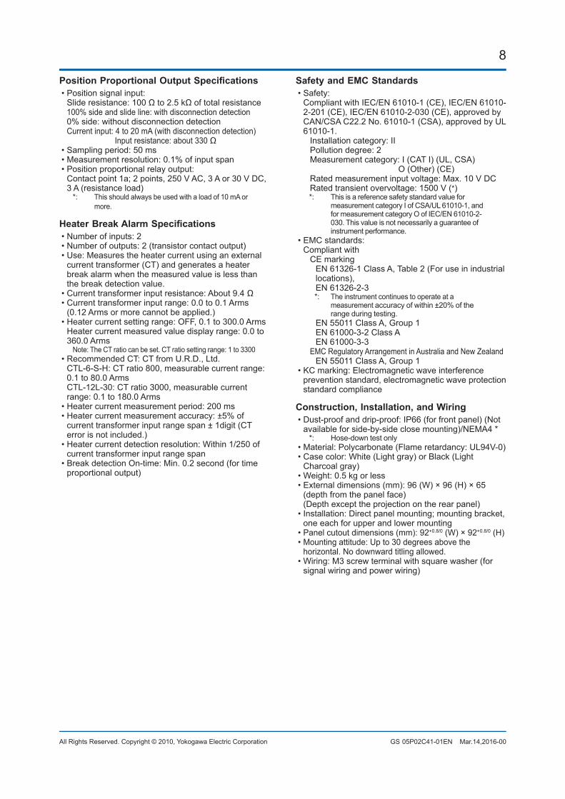
PositionProportionalOutputSpecifications• Position signal input: Slideresistance:100Ωto2.5kΩoftotalresistance 100% side and slide line: with disconnection detection 0% side: without disconnection detection Current input: 4 to 20 mA (with disconnection detection) Input resistance: about 330 Ω• Sampling period: 50 ms• Measurement resolution: 0.1% of input span• Position proportional relay output: Contact point 1a; 2 points, 250 V AC, 3 A or 30 V DC,
3 A (resistance load)*: This should always be used with a load of 10 mA or
more.
HeaterBreakAlarmSpecifications• Number of inputs: 2• Number of outputs: 2 (transistor contact output)• Use: Measures the heater current using an external
current transformer (CT) and generates a heater break alarm when the measured value is less than the break detection value.
•Currenttransformerinputresistance:About9.4Ω• Current transformer input range: 0.0 to 0.1 Arms
(0.12 Arms or more cannot be applied.)• Heater current setting range: OFF, 0.1 to 300.0 Arms Heater current measured value display range: 0.0 to
360.0 ArmsNote: The CT ratio can be set. CT ratio setting range: 1 to 3300
• Recommended CT: CT from U.R.D., Ltd. CTL-6-S-H: CT ratio 800, measurable current range:
0.1 to 80.0 Arms CTL-12L-30: CT ratio 3000, measurable current
range: 0.1 to 180.0 Arms• Heater current measurement period: 200 ms• Heater current measurement accuracy: ±5% of
current transformer input range span ± 1digit (CT error is not included.)
• Heater current detection resolution: Within 1/250 of current transformer input range span
• Break detection On-time: Min. 0.2 second (for time proportional output)
Safety and EMC Standards• Safety: Compliant with IEC/EN 61010-1 (CE), IEC/EN 61010-
2-201 (CE), IEC/EN 61010-2-030 (CE), approved by CAN/CSA C22.2 No. 61010-1 (CSA), approved by UL 61010-1.
Installation category: II Pollution degree: 2 Measurement category: I (CAT I) (UL, CSA) O (Other) (CE) Rated measurement input voltage: Max. 10 V DC Rated transient overvoltage: 1500 V (*)
*: This is a reference safety standard value for measurement category I of CSA/UL 61010-1, and for measurement category O of IEC/EN 61010-2-030. This value is not necessarily a guarantee of instrument performance.
• EMC standards: Compliant with CE marking EN 61326-1 Class A, Table 2 (For use in industrial locations), EN 61326-2-3
*: The instrument continues to operate at a measurement accuracy of within ±20% of the range during testing.
EN 55011 Class A, Group 1 EN 61000-3-2 Class A EN 61000-3-3 EMC Regulatory Arrangement in Australia and New Zealand EN 55011 Class A, Group 1• KC marking: Electromagnetic wave interference
prevention standard, electromagnetic wave protection standard compliance
Construction, Installation, and Wiring• Dust-proof and drip-proof: IP66 (for front panel) (Not
available for side-by-side close mounting)/NEMA4 **: Hose-down test only
• Material: Polycarbonate (Flame retardancy: UL94V-0)• Case color: White (Light gray) or Black (Light
Charcoal gray)• Weight: 0.5 kg or less• External dimensions (mm): 96 (W) × 96 (H) × 65
(depth from the panel face) (Depth except the projection on the rear panel)• Installation: Direct panel mounting; mounting bracket,
one each for upper and lower mounting• Panel cutout dimensions (mm): 92+0.8/0 (W) × 92+0.8/0 (H)• Mounting attitude: Up to 30 degrees above the
horizontal. No downward titling allowed.• Wiring: M3 screw terminal with square washer (for
signal wiring and power wiring)

9
All Rights Reserved. Copyright © 2010, Yokogawa Electric Corporation GS 05P02C41-01EN Mar.14,2016-00
PowerSupplySpecificationsandIsolation• Power supply: Rated voltage: 100-240 V AC (+10%/-15%), 50/60 Hz 24 V AC/DC (+10%/-15%) (for /DC option)• Power consumption: 18 VA (24 V DC:9 VA, 24 V AC: 14VAif/DCoptionisspecified)
• Data backup: Nonvolatile memory• Power holdup time: 20 ms (for 100 V AC drive)• Withstanding voltage Between primary terminals and secondary terminals:
2300 V AC for 1 minute (UL, CSA) Between primary terminals and secondary terminals:
3000 V AC for 1 minute (CE) Between primary terminals: 1500 V AC for 1 minute Between secondary terminals: 500 V AC for 1 minute
(Primary terminals: Power* and relay output terminals; Secondary terminals: Analog I/O signal terminals, contact input terminals, communication terminals and functional grounding terminals.)
*: Power terminals for 24V AC/DC models are the secondary terminals.
• Insulation resistance: Between power supply terminals and agroundingterminal20MΩormoreat500VDC
•IsolationspecificationsPV (universal ) input terminals
Remote (universal) input terminals with direct input / Remote input terminals
Aux. analog (AIN2) input terminals
Control relay (contact point c) output terminals
PV event-1 relay (contact point a) output terminals
PV event-2 relay (contact point a) output terminals
PV event-3 relay (contact point a) output terminalsPosition proportional relay output terminals
Contact input terminals (all)RS-485 communication terminals (2 ports)
Contact output (transistor) terminals
Ethernet communication terminal
PROFIBUS-DP/DeviceNet/CC-Link communication terminalsCurrent transformer input terminals
Control, retransmission (analog) output terminals(not isolated between the analog output terminals)Valve position (feedback) input terminals
Internalcircuits
Powersupply
The circuits divided by lines are insulated mutually.
Aux. analog (AIN4) input terminals
Environmental ConditionsNormal Operating Conditions:•Ambienttemperature:-10to50ºC(side-by-sideclosemounting:-10to40ºC)
0to50°CiftheCC-Linkoptionisspecified.(side-by-side mounting: 0 to 40 °C)
• Ambient humidity: 20 to 90% RH (no condensation allowed)•Magneticfield:400A/morless• Continuous vibration at 5 to 9 Hz: Half amplitude of
1.5 mm or less, 1oct/min for 90 minutes each in the three axis directions
Continuous vibration at 9 to 150 Hz: 4.9 m/s2 or less, 1oct/min for 90 minutes each in the three axis directions
• Short-period vibration: 14.7 m/s2, 15 seconds or less• Shock: 98 m/s2 or less, 11 ms• Altitude: 2000 m or less above sea level• Warm-up time: 30 minutes or more after the power is
turned on• Startup time: Within 10 seconds
*: The LCD (a liquid crystal display) is used for a display portion of this product. The LCD has a characteristic that the display action becomes late at the low temperature. However, the control functionisnotaffected.
Transportation and Storage Conditions:•Temperature:-25to70ºC•Temperaturechangerate:20ºC/horless• Humidity: 5 to 95% RH (no condensation allowed)EffectsofOperatingConditions•Effectofambienttemperature: VoltageorTCinput:±1µV/ºCor±0.01%ofF.S./ºC,
whichever is larger Currentinput:±0.01%ofF.S./ºC RTDinput:±0.05ºC/ºC(ambienttemperature)orless Analogoutput:±0.02%ofF.S./ºCorless•Effectofpowersupplyvoltagefluctuation Analog input: ±0.05% of F.S. or less Analog output: ±0.05% of F.S. or less (Each within rated voltage range)
Time accuracyClock time accuracy: 50 ppmFor example, the time deviation per month is 0.00005×30 days × 24 hours × 3600 seconds =129.6 seconds.
10
All Rights Reserved. Copyright © 2010, Yokogawa Electric Corporation GS 05P02C41-01EN Mar.14,2016-00
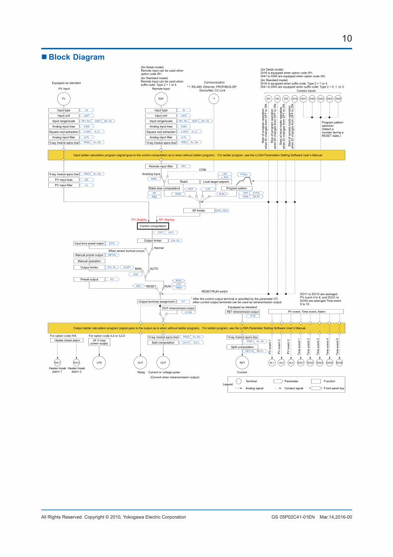
n Block Diagram
Program pattern
Local target setpointReset
COMAnaolog input
*1
Output limiter
Manual operation
Manual preset output
Input error preset output
Preset output
RESET/RUN switch
AUTO
When sensor burnout occursNormal
MAN
RUNRESET
SP limiter
DI45PV RSP
Input type
Input unit
Input range/scale
Analog input bias
Square root extraction
Analog input filter
Input type
Input unit
Input range/scale
Analog input bias
Square root extraction
Analog input filter
10-seg. linearizer approx./bias
Remote input filter
PV input bias
PV input filterRatio bias computation
Output limiter
A.BS
A.FL
BS
FL
PMD An, Bn
10-seg. linearizer approx./bias PMD An, Bn
PMD An, Bn
CNT ALG
TSP S.PID
PTNO.
TIME TM.RT
L.PIDLSP
RTRBS
REM
LOC
RMS
SPH, SPL
RFL
A.SR A.LC
UNIT
IN
RH, RL SDP SH, SL
A.BS
A.FL
10-seg. linearizer approx./bias
A.SR A.LC
UNIT
IN
RH, RL SDP SH, SL
EPOOH, OL
OH, OL OLMT
PO
MPON
OT
Equipped as standard
For option code /HAHeater break alarm
HAL2HAL1
Heater breakalarm 1
Heater breakalarm 2 Current or voltage pulseRelay Current
OUTOUT RET AL3AL2AL1
PMD
OU.H OU.L
An, Bn
Split computation
10-seg. linearizer approx./bias
RET.H RET.L
PMD An, Bn
Split computation
10-seg. linearizer approx./bias
OUT retransmission outputO1RS RET retransmission output
RTS
* After the control output terminal is specified by the parameter OT, other current output terminals can be used as retransmission output.Output terminal assignment
DI44DI43DI42DI41DI3DI2DI1 DI16
RUN
RST
Control computation
(Current when retransmission output)
Communication*1: RS-485, Ethernet, PROFIBUS-DP,
DeviceNet, CC-LinkPV input Remote inputContact inputs
Equipped as standard(for Standard model)DI16 is equipped when suffix code: Type 2 = 1 or 4.DI41 to DI45 are equipped when suffix code: Type 2 = 0, 1, or 3.
(for Standard model)Remote input can be used whensuffix code: Type 2 = 1 or 4.
Terminal Parameter Function
Analog signal Contact signal Front panel keyLegend
PV
eve
nt 1
PV
eve
nt 2
PV
eve
nt 3
Tim
e ev
ent 1
Tim
e ev
ent 2
Tim
e ev
ent 3
Tim
e ev
ent 4
DO23DO22DO21 DO24
Tim
e ev
ent 5
DO25
PV display SP display
Input ladder calculation program (signal goes to the control computation as is when without ladder program). For ladder program, see the LL50A Parameters Setting Software User’s Manual.
Output ladder calculation program (signal goes to the output as is when without ladder program). For ladder program, see the LL50A Parameter Setting Software User’s Manual.
Sta
rt of
pro
gram
ope
ratio
nw
hen
DI c
hang
es fr
om O
FF to
ON
.
Sto
p of
pro
gram
ope
ratio
nw
hen
DI c
hang
es fr
om O
FF to
ON
.
Sta
rt of
loca
l-mod
e op
erat
ion
whe
n D
I cha
nges
from
OFF
to O
N.
Sta
rt of
rem
ote-
mod
e op
erat
ion
whe
n D
I cha
nges
from
OFF
to O
N.
RST REM
A/M
LOCRUN
PV event, Time event, Alarm
Program pattern selection(Select a number during a RESET state.)
DO11 to DO15 are assinged PV event 4 to 8, and DO31 to DO35 are assinged Time event 6 to 10.
(for Detail model)DI16 is equipped when option code /R1.DI41 to DI45 are equipped when option code /X4.
(for Detail model) Remote input can be used whenoption code /R1.
LPS
24 V looppower supply
For option code /L4 or /LC4
11
All Rights Reserved. Copyright © 2010, Yokogawa Electric Corporation GS 05P02C41-01EN Mar.14,2016-00
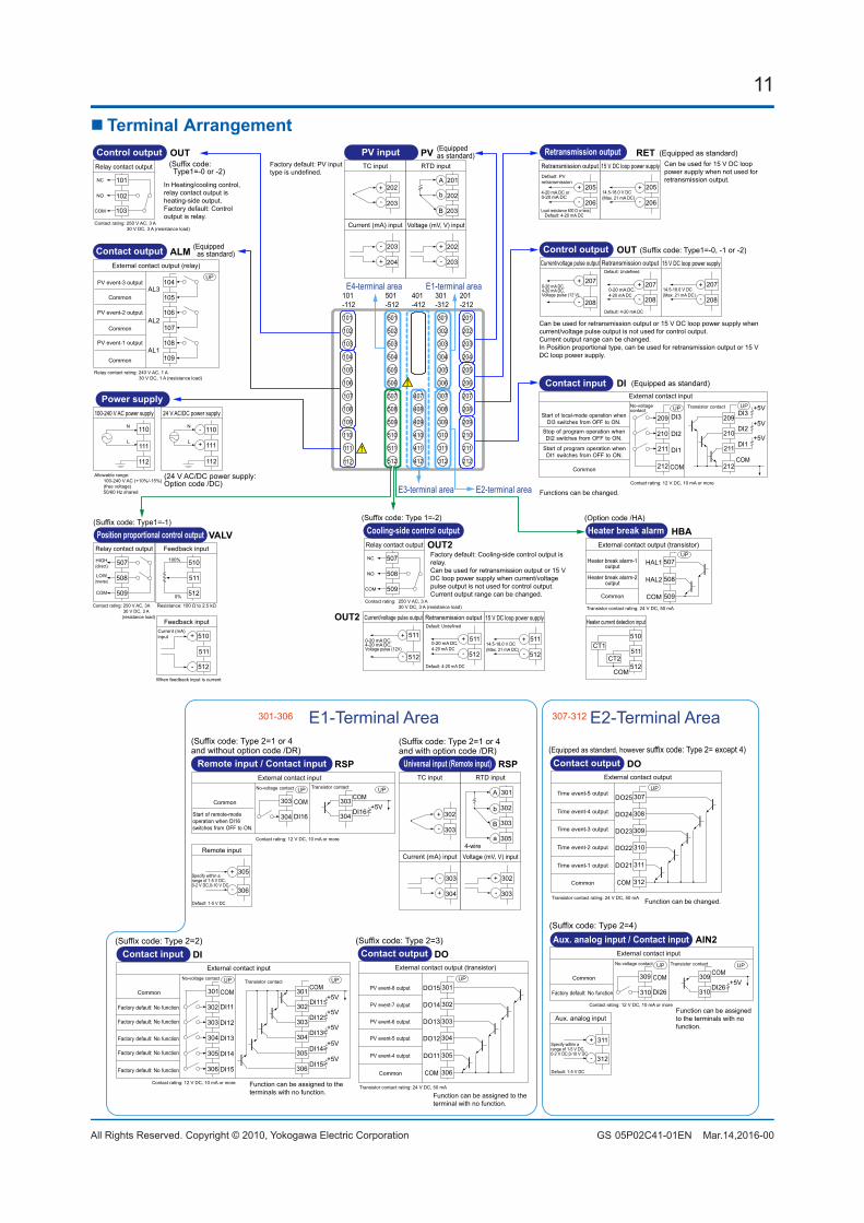
n Terminal Arrangement
E4-terminal area
E3-terminal area E2-terminal area
E1-terminal area
101
102
103
104
105
106
107
108
109
110
111
501
502
503
504
505
506
507
508
509
510
511
512
407
408
409
410
411
412
301
302
303
304
305
306
307
308
309
310
311
312
201
202
203
204
205
206
207
208
209
210
211
212
101-112
501-512
401-412
301-312
201-212
ALM (Equipped as standard)Contact output
External contact output (relay)
AL3
AL2
AL1
Relay contact rating: 240 V AC, 1 A 30 V DC, 1 A (resistance load)
PV event-2 output
PV event-3 output
PV event-1 output
Common
Common
Common
UP104
105
106
107
108
109
PVPV inputTC input RTD input
Voltage (mV, V) input
A
+
-
+
-
Current (mA) input
+
-
B
b
(Equippedas standard)
202
203
201
202
203
202
203
203
204
Factory default: PV input type is undefined.
OUT(Suffix code: Type1=-0 or -2)
Control output
101
102
Relay contact output
103
NC
NO
COM
Contact rating: 250 V AC, 3 A 30 V DC, 3 A (resistance load)
In Heating/cooling control, relay contact output is heating-side output.Factory default: Control output is relay.
OUTCurrent/voltage pulse output
0-20 mA DC,4-20 mA DC,Voltage pulse (12 V)
+
Retransmission output
+
-
Default: 4-20 mA DC
Default: Undefined
0-20 mA DC,4-20 mA DC
Control output (Suffix code: Type1=-0, -1 or -2)
15 V DC loop power supply
14.5-18.0 V DC(Max. 21 mA DC)
+
-
207
208
207
- 208
207
208
Can be used for retransmission output or 15 V DC loop power supply when current/voltage pulse output is not used for control output.Current output range can be changed.In Position proportional type, can be used for retransmission output or 15 V DC loop power supply.
OUT2
OUT2
(Suffix code: Type 1=-2)
Current/voltage pulse output
0-20 mA DC,4-20 mA DC,Voltage pulse (12V)
+
-
Retransmission output
+
-
Default: 4-20 mA DC
Default: Undefined
0-20 mA DC,4-20 mA DC
Cooling-side control outputRelay contact output
NC
NO
COM
Contact rating: 250 V AC, 3 A 30 V DC, 3 A (resistance load)
15 V DC loop power supply
14.5-18.0 V DC(Max. 21 mA DC)
+
-
511
512
507
508
509
511
512
511
512
Factory default: Cooling-side control output is relay.Can be used for retransmission output or 15 V DC loop power supply when current/voltage pulse output is not used for control output. Current output range can be changed.
RETRetransmission output
4-20 mA DC or0-20 mA DC
15 V DC loop power supply
14.5-18.0 V DC(Max. 21 mA DC)
+
-
+
-
Default: 4-20 mA DC
Default: PV retransmission
Load resistance 600 Ω or less
Retransmission output (Equipped as standard)
205
206
205
206
Can be used for 15 V DC loop power supply when not used for retransmission output.
VALV(Suffix code: Type1=-1)
Position proportional control output
Resistance: 100 Ω to 2.5 kΩ
Feedback input100%
0%
Relay contact output
HIGH(direct)
LOW(reverse)
COM
Contact rating: 250 V AC, 3A 30 V DC, 3 A (resistance load)
507
508
509
510
511
512
-
Feedback inputCurrent (mA)input
When feedback input is current
510
511
512
+
HBA(Option code /HA)
Heater break alarm
Heater current detection input
CT1
CT2
COM
External contact output (transistor)
Transistor contact rating: 24 V DC, 50 mA
Heater break alarm-1output
Heater break alarm-2output
Common
510
511
512
HAL1
HAL2
COM
UP507
508
509
112
(24 V AC/DC power supply: Option code /DC)
Power supply100-240 V AC power supply
N
L
Allowable range: 100-240 V AC (+10%/-15%) (free voltage) 50/60 Hz shared
110
111
24 V AC/DC power supply
-
+
110
111
112 112
N
L
DI (Equipped as standard)Contact input
Contact rating: 12 V DC, 10 mA or more
External contact input
DI3
DI2
DI1
COMCommon
DI3
DI2
DI1
COM
+5V
+5V
+5V
No-voltagecontact
Transistor contactUP UP
209
210
211
212
209
210
211
212
Functions can be changed.
Start of program operation when DI1 switches from OFF to ON.
Stop of program operation when DI2 switches from OFF to ON.
Start of local-mode operation when DI3 switches from OFF to ON.
E1-Terminal Area301-306 E2-Terminal Area307-312
(Suffix code: Type 2=2)Contact input
External contact input
DI11
DI12
DI13
DI14
DI15
COMCommon
DI11
DI12
COM+5V
+5V
No-voltage contactTransistor contact
Contact rating: 12 V DC, 10 mA or more
DI13+5V
DI14+5V
DI15+5V
Factory default: No function
Factory default: No function
Factory default: No function
Factory default: No function
Factory default: No function
UP UP
301
302
303
304
305
306
301
302
303
304
305
306
Function can be assigned to the terminals with no function.
DI Contact outputExternal contact output (transistor)
Transistor contact rating: 24 V DC, 50 mA
DO12
DO11
DO13
DO14
DO15
COMCommon
UP
(Suffix code: Type 2=3)
PV event-4 output
PV event-5 output
PV event-6 output
PV event-7 output
PV event-8 output 301
302
303
304
305
306
Function can be assigned to the terminal with no function.
DO
(Suffix code: Type 2=1 or 4and with option code /DR)
Universal input (Remote input)TC input RTD input
Voltage (mV, V) input
+
-
+
-
Current (mA) input
+
-
4-wire
302
303
302
303
303
304
RSP
a
B
b
A 301
302
303
305
Contact outputExternal contact output
Transistor contact rating: 24 V DC, 50 mA
DO22
DO21
DO23
DO24
DO25
COMCommon
UP
(Equipped as standard, however suffix code: Type 2= except 4)
307
308
309
310
311
312
Function can be changed.
DO
Time event-5 output
Time event-4 output
Time event-3 output
Time event-2 output
Time event-1 output
(Suffix code: Type 2=4)
Aux. analog input
Default: 1-5 V DC
+
-
Aux. analog input / Contact inputExternal contact input
DI26
COMCommon
DI26
COM+5V
No-voltage contact Transistor contact
Contact rating: 12 V DC, 10 mA or more
Factory default: No function
UP UP
309
310
309
310
311
312
Function can be assigned to the terminals with no function.
AIN2
Specify within a range of 1-5 V DC, 0-2 V DC,0-10 V DC
(Suffix code: Type 2=1 or 4and without option code /DR)
Remote input
Default: 1-5 V DC
+
-
Remote input / Contact inputExternal contact input
DI16
COMCommon
DI16
COM+5V
No-voltage contact Transistor contact
Contact rating: 12 V DC, 10 mA or more
UP UP
303
304
303
304
305
306
RSP
Specify within a range of 1-5 V DC, 0-2 V DC,0-10 V DC
Start of remote-mode operation when DI16 switches from OFF to ON.
12
All Rights Reserved. Copyright © 2010, Yokogawa Electric Corporation GS 05P02C41-01EN Mar.14,2016-00
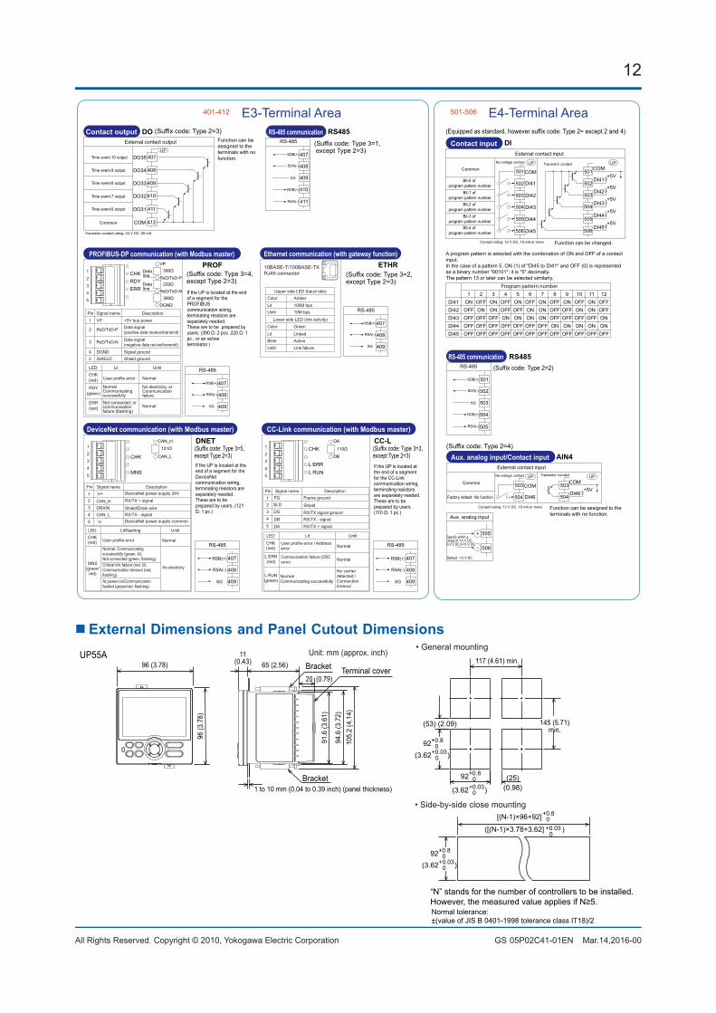
E3-Terminal Area401-412 E4-Terminal Area501-506
(Suffix code: Type 3=2, except Type 2=3)
Ethernet communication (with gateway function)
10BASE-T/100BASE-TXRJ45 connector
ColorLitUnlit
Amber100M bps10M bps
Green
LinkedActiveLink failure
Color
LitBlinkUnlit
Upper side LED (baud rate)
Lower side LED (link activity)
RS-485
RSB(+)
RSA(-)
SG
407
408
409
ETHR
RS-485
SDB(+)
SDA(-)
RDB(+)
RDA(-)
SG
RS-485 communication(Suffix code: Type 3=1, except Type 2=3)
407
408
409
410
411
RS485Contact input
External contact input
DI41
DI42
DI43
DI44
DI45
COMDI41
DI42
COM+5V
+5V
DI43+5V
DI44+5V
DI45+5V
UP UP
(Equipped as standard, however suffix code: Type 2= except 2 and 4)
CommonNo-voltage contact Transistor contact
Contact rating: 12 V DC, 10 mA or more
Bit-0 of program pattern number
Bit-1 of program pattern number
Bit-2 of program pattern number
Bit-3 of program pattern number
Bit-4 of program pattern number
501
502
503
504
505
506
501
502
503
504
505
506
Function can be changed.
DIContact output
External contact output
DO32
DO31
DO33
DO34
DO35
COM
Time event-6 output
Time event-7 output
Time event-8 output
Time event-9 output
Time event-10 output
Common
UP
(Suffix code: Type 2=3)
407
408
409
410
411
412
DO
Transistor contact rating: 24 V DC, 50 mA
Function can be assigned to the terminals with no function.
RS-485
SDB(+)
SDA(-)
RDB(+)
RDA(-)
SG
RS-485 communication
501
502
503
504
505
RS485(Suffix code: Type 2=2)
Aux. analog input
Default: 1-5 V DC
+
-
Aux. analog input/Contact inputExternal contact input
DI46
COMDI46
COM+5V
UP UP
(Suffix code: Type 2=4)
Common
No-voltage contact Transistor contact
Contact rating: 12 V DC, 10 mA or more
Factory default: No function
503
504
503
504
505
506
Function can be assigned to the terminals with no function.
AIN4
Specify within a range of 1-5 V DC, 0-2 V DC,0-10 V DC
A program pattern is selected with the combination of ON and OFF of a contact input.In the case of a pattern 5, ON (1) of "DI45 to DI41" and OFF (0) is represented as a binary number "00101": it is "5" decimally.The pattern 13 or later can be selected similarly.
Program pattern number 1 2 3 4 5 6 7 8 9 10 11 12DI41 ON OFF ON OFF ON OFF ON OFF ON OFF ON OFFDI42 OFF ON ON OFF OFF ON ON OFF OFF ON ON OFFDI43 OFF OFF OFF ON ON ON ON OFF OFF OFF OFF ONDI44 OFF OFF OFF OFF OFF OFF OFF ON ON ON ON ONDI45 OFF OFF OFF OFF OFF OFF OFF OFF OFF OFF OFF OFF
(Suffix code: Type 3=5, except Type 2=3)
DeviceNet communication (with Modbus master)
RS-485
RSB(+)
RSA(-)
SG
407
408
409
DNET
If the UP is located at the end of a segment for the DeviceNetcommunication wiring,terminating resistors are separately needed.These are to be prepared by users. (121 Ω: 1 pc.)
CAN_H
CAN_L
121Ω
LEDCHK(red)
MNS(green/
red)
Lit/flashing Unlit
User profile error Normal
Pin12
Signal name Description
CAN_H
CAN_L
3
V+
4
V-5
DRAIN
RX/TX + signal
RX/TX - signalShield/Drain wire
DeviceNet power supply 24V
DeviceNet power supply common
Normal. Communicating successfully (green, lit).Not connected (green, flashing).Critical link failure (red, lit).Communication timeout (red, flashing)At power-on/Communication faulted (green/red, flashing)
No electricity
CHK
MNS
1
2
3
4
5
(Suffix code: Type 3=3, except Type 2=3)
CC-Link communication (with Modbus master)
RS-485
RSB(+)
RSA(-)
SG
407
408
409
CC-L
If the UP is located at the end of a segment for the CC-Linkcommunication wiring,terminating resistors are separately needed.These are to be prepared by users. (110 Ω: 1 pc.)
DA
DB
110Ω
LED
CHK(red)
L ERR(red)
L RUN(green)
Lit Unlit
Normal
Normal
Pin12
Signal name Description
DADB
3 DG4
SLD
5
FG
RX/TX + signalRX/TX - signal
Frame ground
RX/TX signal ground
Shield
Normal Communicating successfully
Communication failure (CRC error)
No carrier detected / Connection timeout
CHK
L RUNL ERR
1
2
3
4
5
PROFIBUS-DP communication (with Modbus master)
Pin1
2
Signal name DescriptionVP
RxD/TxD-P
3 RxD/TxD-N
4 DGND5 SHIELD
+5V bus powerData signal (positive data receive/transmit)
Data signal (negative data recive/transmit)
Signal groundShield ground
RS-485
RSB(+)
RSA(-)
SG
407
408
409
PROF
If the UP is located at the end of a segment for the PROFIBUScommunication wiring,terminating resistors are separately needed.These are to be prepared by users. (390 Ω: 2 pcs. 220 Ω: 1 pc., or an activeterminator.)
VP
RxD/TxD-PData line
Data line
390Ω
220Ω
390ΩRxD/TxD-N
DGND
LEDCHK(red)
RDY(green)
Lit Unlit
ERR(red)
User profile error Normal
NormalNot connected, orcommunicationfailure (flashing)
NormalCommunicatingsuccessfully
No electricity, or Communication failure
(Suffix code: Type 3=4, except Type 2=3)
CHKRDYERR
1
2
3
4
5
User profile error / Address error
nExternalDimensionsandPanelCutoutDimensions
(25)
(53) (2.09)
[(N-1)×96+92]
117 (4.61) min.
145 (5.71)min.
+0.80
+0.8092
“N” stands for the number of controllers to be installed.However, the measured value applies if N≥5.
65 (2.56)
20 (0.79)
11(0.43)
UP55A
1 to 10 mm (0.04 to 0.39 inch) (panel thickness)Bracket
Bracket
94.6
(3.7
2)
91.6
(3.6
1)
105.
2 (4
.14)
Unit: mm (approx. inch)96 (3.78)
96 (3
.78)
• General mounting
• Side-by-side close mounting
Terminal cover
Normal tolerance: ±(value of JIS B 0401-1998 tolerance class IT18)/2
+0.8092
+0.030(3.62 )
(0.98)+0.030(3.62 )
+0.8092
+0.030(3.62 )
([(N-1)×3.78+3.62] )+0.030

13
All Rights Reserved. Copyright © 2010, Yokogawa Electric Corporation GS 05P02C41-01EN Mar.14,2016-00Subject to change without notice.
nModelandSuffixCode
Model Suffixcode Option code Description
UP55A
Program Controller (Power supply: 100-240 V AC)30 program patterns / 300 program segments (99 program patterns / 600 program segments when the option /AP is specifed. Max. 99 segments per pattern)(provided with retransmission output or 15 V DC loop power supply, 8 DIs, and 8 DOs)
Type 1: Basic control
-0 Standard type-1 Position proportional type-2 Heating/cooling type
Type 2:Functions
0 None1 Remote (1 additional aux. analog) input, 1 additional DI2 RS-485 communication (Max.19.2 kpbs, 2-wire/4-wire)3 10 additional DOs (*1)
4 3 additional aux. analog inputs, 2 DIs and 5 DOs to be deleted
Type 3:Open networks
0 None1 RS-485 communication (Max.38.4 kbps, 2-wire/4-wire)2 Ethernet communication (with serial gateway function)3 CC-Link communication (with Modbus master function)4 PROFIBUS-DP communication (with Modbus master function)5 DeviceNet communication (with Modbus master function)
Display language (*2)
-1 English (Default. Can be switched to other language by the setting.)-2 German (Default. Can be switched to other language by the setting.)-3 French (Default. Can be switched to other language by the setting.)-4 Spanish (Default. Can be switched to other language by the setting.)
Case color0 White (Light gray)1 Black (Light charcoal gray)
Fixed code -00 Always “-00” (for Standard Code Model)
Option codes
/AP 69 additional patterns/300 additional segments/DR Additional direct input (TC and 3-wire/4-wire RTD) and current input to Remote (1
additional aux. analog) input, 1 DI to be deleted (*3)
/HA Heater break alarm (*4)
/DC Power supply 24 V AC/DC/CT Coating (*5)
*1: WhentheType2codeis“3”,only“0”canbespecifiedfortheType3code.*2: English, German, French, and Spanish are available for the guide display.*3: The/DRoptioncanbespecifiedonlywhentheType2codeis“1”or“4.”*4: The/HAoptioncanbespecifiedonlywhentheType1codeis“-0.”*5: Whenthe/CToptionisspecified,theUP55Adoesnotconformtothesafetystandards(ULandCSA)andCEmarking(Productswith/CT
option are not intended for EEA-market).
nItemstobespecifiedwhenordering Modelandsuffixcodes,whetherUser’sManualand
QIC required.
n Standard accessories Terminal cover, Brackets (mounting hardware), Unit
label, and Operation Guide for Single-loop Control.
n Special Order ItemsName Model
Terminal cover UTAP001User’s Manual (CD) UTAP003
Model code Suffixcode DescriptionLL50A -00 Parameter Setting SoftwareX010 See the General
Specifications(*)Resistance Module
*: Necessary to input the current signal to the voltage input terminal.
User’s ManualProduct user’s manuals can be downloaded or viewed at the following URL. To view the user’s manual, you need to use Adobe Reader 7 or later by Adobe Systems.URL: http://www.yokogawa.com/ns/ut/im/