Embed Size (px)
Citation preview
INSTITUT GRAĐEVINARSTVA HRVATSKE
GENERAL TECHNICAL REQUIREMENTS FOR ROAD WORKS
VOLUME V
ROAD TUNNELS
CLIENTS:
HRVATSKE CESTE HRVATSKE AUTOCESTE
Zagreb 2001
Published by:
Institut građevinarstva Hrvatske, Zagreb, Janka Rakuše 1
For the publisher:
Smiljan Jurić MSc CEng
Coordinators:
Prof. Petar Đukan PhD CEng Zdravko Tomljanović, BSc CE
Editors:
Ivan Banjad, BSc CEng Stjepan Bezak, PhD CEng
Mijo Ereš, BSc CEng
Reviewer:
Antun Szavits Nossan PhD CEng
Preparation supervisors:
Stjepan Bezak, PhD CEng (8-00) Mijo Ereš, BSc CEng (8-01, 8-04)
Ivan Banjad, BSc CEng (8-02) Aleksej Dušek, BSc CEng (8-03, 8-05)
Jovo Beslać PhD CEng (8-06)
Contributors:
Ivan Banjad, BSc CEng (8-00, 8-03) Mijo Ereš BSc CEng (8-00)
Stjepan Bezak PhD CEng (8-01) Ranko Gradečak BSc CEng, BSc GeodEng (8-01, 8-02, 8-03)
Aleksej Dušek BSc CEng (8-02) Branko Stojković MSc CEng (8-02, 8-03, 8-06)
Darko Šarić BSc CEng (8-02, 8-03) Jovo Beslać PhD CEng (8-03, 8-05)
Zvonko Varga CE (8-04) Božidar Segedi MSc ChemEng (8-05) Marijan Banovac MSc MechEng (8-06)
Printed by:
Sveučilišna tiskara d.o.o. Trg m. Tita 14, Zagreb
General Technical Requirements for Road Works 2001 - VOLUME V Page 2
Foreword
0-00 INTRODUCTION
General Technical Requirements for Road Works (GTR) contain requirements for the realization of individual works necessary for the completion of road construction projects, and they form an integral part of the corresponding contracts. If the technical documentation calls for realization of works not comprised in these GTR, the Designer will prepare Special Technical Requirements (STR) for these works, and the STR will constitute an addendum to these General Technical Requirements.
This is the third revised edition of the General Technical Requirements (GTR). The first edition was published in 1976, and the second in 1989. Experience gained in practical work has been incorporated as appropriate in these General Technical Requirements for Road Works.
These GTR 2001 are composed of the following volumes:
Volume I General Provisions and Preliminary Work Volume II Earthwork, Drainage, Retaining and Facing Walls, Volume III Pavement Structure, Volume IV Concrete Work, Volume V Road Tunnels, and Volume VI Road Furniture.
This 2001 edition of GTR consists of six Volumes which together form a single entity. When it is specified in a contract, technical document or cost estimate that a work is to be carried out in accordance with any provision contained in any one of these Volumes, the Contractor will be required to perform such work in accordance with all relevant provisions of these GTR.
These General Technical Requirements were prepared by Institut građevinarstva Hrvatske (Civil Engineering Institute of Croatia).
0-00.1 ABBREVIATIONS
Appropriate abbreviations of terms used in these GTR are explained as follows:
GTR General Technical Requirements for Road Works CMD Construction Management Design STR Special Technical Requirements GRCC General Requirements for Construction Contracts SRCC Special Requirements for Construction Contracts QCQAP Quality Control and Quality Assurance Program SOS-NCS State Office for Standardization – National Certification Service BL Building Law of the Republic of Croatia SL Standardization Law of the Republic of Croatia HRN Croatian standard ISO International Organization of Standardization EN European Standard DIN German standard (Deutsches Institut für Normung) ASTM American Society for Testing and Materials
General Technical Requirements for Road Works 2001 - VOLUME V Page 3

0-00.2 GENERAL NOTES
These GTR set minimum quality requirements for materials, products and works. The GTR are written in such a way that they can form a part of a contract while requirements relating to special works will be included in the contract as Special Technical Requirements (STR). The GTR take into account all applicable Croatian regulations and technical standards (HRN).
0-00.3 USE OF THESE GENERAL TECHNICAL REQUIREMENTS
These GTR contain technical requirements for the performance of works, methods for quality assurance and quality assessment, and methods for calculation of completed work. The GTR are applicable to works contained in cost estimates of projects, but also to works subsequently defined on the site to ensure full completion of the work specified in the contract. On some projects, special requirements may also be specified to take into account various additional requirements, i.e. particular features of the project. The use of GTR is mandatory when they form an integral part of technical documents of the contract.
General Technical Requirements for Road Works 2001 - VOLUME V Page 4
8 ROAD TUNNELS
ROAD TUNNELS
CONTENTS:
8-00 GENERAL PROVISIONS AND DEFINITIONS 8-00.1 GENERAL PROVISIONS 8-00.2 DEFINITION OF TERMS USED IN ROAD TUNNELING WORK 8-00.3 SITE INVESTIGATION REPORT 8-00.4 SAFETY AT WORK 8-00.5 PAVEMENT STRUCTURE 8-00.6 PORTALS 8-00.7 SEPARATORS 8-00.8 TRAFFIC SIGNS AND MARKINGS 8-00.9 STANDARDS AND TECHNICAL REGULATIONS
8-01 PRELIMINARY WORK 8-01.1 CONSTRUCTION SITE
8-01.1.1 Construction of approach to construction site 8-01.1.2 Construction of site roads 8-01.1.3 Erection of storage depot for explosive substances 8-01.1.4 Construction of compressor station and air-duct distribution system 8-01.1.5 High voltage connection and transformer station 8-01.1.6 Connection for supplying the site with water 8-01.1.7 Disposal of excavated material and evacuation of water from the
tunnel 8-01.1.8 Other
8-01.2 WORKING ENVIRONMENT 8-01.2.1 General 8-01.2.2 Submittal of documents 8-01.2.3 Realization 8-01.2.4 Calculation of work and payment
8-01.3 CONSTRUCTION OF APPROACH CUTTINGS 8-01.3.1 Protection of the face of the approach cutting
8-01.4 STANDARDS AND TECHNICAL REGULATIONS 8-02 TUNNEL EXCAVATION
8-02.0 GENERAL PROVISIONS 8-02.0.1 Classification of excavation work 8-02.0.2 Special provisions 8-02.0.3 Working design 8-02.0.4 Realization
8-02.1 EXCAVATION WORK 8-02.1.1 Rock mass class I 8-02.1.2 Rock mass class II 8-02.1.3 Rock mass class III 8-02.1.4 Rock mass class IV 8-02.1.5 Rock mass class V 8-02.1.6 Overbreak
General Technical Requirements for Road Works 2001 - VOLUME V Page 6
8-02.2 CALCULATION OF EXCAVATION WORK
ROAD TUNNELS
8-02.3 PAYMENT 8-02.4 STANDARDS AND TECHNICAL REGULATIONS
8-03 SUPPORT WORK IN TUNNELS 8-03.0 GENERAL
8-03.0.1 Submittal of documents 8-03.0.2 Records 8-03.0.3 Supply of equipment and material 8-03.0.4 Geotechnical monitoring 8-03.0.4.1 Determination of rock mass quality along the tunnel route 8-03.0.4.2 Geotechnical monitoring and measurement program 8-03.0.4.3 Procedure for geotechnical monitoring of tunneling work 8-03.0.5 Topographic survey of the profile
8-03.1 TUNNEL SUPPORT WORK 8-03.1.1 Shotcrete 8-03.1.2 Reinforcing steel 8-03.1.2.1 Steel fabric 8-03.1.2.2 Reinforcing bars 8-03.1.2.3 Steel fiber reinforcement 8-03.1.2.4 Steel arches 8-03.1.2.5 Piles 8-03.1.2.6 Steel lagging 8-03.1.2.7 Rock bolts 8-03.1.2.8 Pipe roof 8-03.1.2.9 Micropiles
8-03.2 GROUTING WORK 8-03.3 CALCULATION OF WORK AND PAYMENT 8-03.4 STANDARDS AND TECHNICAL REGULATIONS
8-04 DRAINAGE 8-04.0 GENERAL
8-04.0.1 Documentation 8-04.1 INTAKE STRUCTURES
8-0.4.1.1 Evacuation of smaller water streams encountered at excavation face
8-04.1.2 Evacuation of bigger water streams encountered at excavation face 8-04.1.3 Evacuation by realization of drainage boreholes
8-04.2 DRAINAGE 8-04.3 PRINCIPAL DRAINAGE SYSTEM
8-04.3.1 Drainage pipe 8-04.3.2 Manholes 8-04.3.3 Transverse pipe connections
8-04.4 HOLLOW CURBS 8-04.5 CURBS 8-04.6 MAINTENANCE SHAFTS AND SIPHONS 8-04.7 STANDARDS AND TECHNICAL REGULATIONS
General Technical Requirements for Road Works 2001 - VOLUME V Page 7
ROAD TUNNELS
8-05 WATERPROOFING 8-05.0 DESCRIPTION
8-05.0.1 Quality requirements for materials 8-05.1 CONSTRUCTION OF WATERPROOFING
8-05.1.1 Shotcrete bedding 8-05.1.2 Geotextile installation - base layer 8-05.1.3 Geotextile installation - Insulating layer 8-05.1.4 Protection of insulating layer
8-05.2 QUALITY CONTROL 8-05.2.1 Initial testing 8-05.2.2 Control testing 8-05.2.3 Audit testing
8-05.3 CALCULATION OF WORK AND PAYMENT 8-05.4 STANDARDS AND TECHNICAL REQUIREMENTS
8-06 CONCRETE WORK 8-06.0 CONCRETE COMPOSITION REQUIREMENTS
8-06.0.1 Workability 8-06.0.2 Formwork stripping time, strength during formwork stripping 8-06.0.3 Crack prevention measures 8-06.0.4 Properties during use
8-06.1 PRINCIPAL COMPONENTS OF CONCRETE 8-06.1.1 Cement 8-06.1.2 Mineral admixtures 8-06.1.3 Aggregate 8-06.1.4 Water 8-06.1.5 Chemical admixtures
8-06.2 CONFORMITY CRITERIA 8-06.3 PRODUCTION CONTROL (AUDIT TESTING AND ACCEPTANCE
TESTING) 8-06.4 REALIZATION OF CONCRETE WORK
8-06.4.1 General 8-06.4.2 Preparations for concrete placement 8-06.4.3 Concrete fabrication and placement 8-06.4.4 Requirements and measures applicable after concreting
8-06.5 SPECIAL PROCEDURES 8-06.6 CALCULATION OF WORK AND PAYMENT 8-06.7 STANDARDS AND TECHNICAL REQUIREMENTS
General Technical Requirements for Road Works 2001 - VOLUME V Page 8

ROAD TUNNELS
8-00 GENERAL PROVISIONS AND DEFINITIONS
8-00.1 GENERAL PROVISIONS
Minimum quality requirements for materials, products and activities used during realization of work in road tunnels. The GTR are written in such a way that they form a part of the contract while requirements relating to special works are included in the contract as Special Technical Requirements (STR).
Materials, products, equipment and works must comply with the standards and technical regulations specified in the design documentation. If no standard is specified, then an appropriate EN (European standard) must be applied. If a standard or regulation becomes invalid during realization of the project, it will be substituted by an appropriate replacement standard or regulation.
The Contractor may propose application of generally recognized technical rules (standards) issued by a foreign standardization body (such as ISO, EN, DIN, ASTM, etc.), subject to written explanation and approval of the Supervising Engineer. This change may be accepted by the Supervising Engineer if approved by the Designer. The Contractor is required to register this change in the working design.
This Volume of General Technical Requirements covers construction and other works realized on road tunnels, but does not provide technical requirements for the realization of specific tunneling equipment and devices, which vary to a great extent depending on local conditions (ventilation, lighting, various measurements and signaling, fire prevention measures, automatic devices, power supply regulation and operation, electricity transfer, etc.).
If some of the above devices, works or equipment are included in the tunnel design, the Designer shall also be required to include Special Technical Requirements (STR) for such work in the final design, and these special requirements will then constitute an integral part of the contract.
8-00.2 DEFINITION OF TERMS USED IN ROAD TUNNELING WORK
General terms and expressions, with the meanings they have in these General Technical Requirements, are presented in section 0. The following terms are additional terms that are especially relevant to this section.
Tunnel is an underground structure situated under the surface of the terrain that is used for various purposes and that emerges to the surface with either one or both ends.
Road tunnel is an underground structure providing space for the operation of road traffic.
Gallery is an usual name for tunnel which is accessible from one side only.
Shaft is a vertical excavation of smaller cross-section.
Drift is a tunnel of smaller cross section.
Top heading is the top (curved) part of the cross section of tunnel.
General Technical Requirements for Road Works 2001 - VOLUME V Page 9
ROAD TUNNELS
Bench is the remaining part of excavation within the final outline of the tunnel.
Tunnel lay-by is the built area outside of the basic cross section of the tunnel.
Portal structure is a separately built structure situated at the entrance and exit of the tunnel.
Vault is a curved roof of an underground room; arch-shaped structure that defines and closes an underground opening.
Crown is the highest point of the tunnel's primary or secondary lining.
Invert is the arch-shaped structure which defines and closes the underground opening below the pavement structure.
Structural lining of the tunnel is the concrete or reinforced-concrete structure in tunnel which is dimensioned in such a way to take on forces generated by underground pressure in all sections.
Tunnel lining is the concrete or reinforced-concrete structure that protects traffic operated in the tunnel.
NATM is an abbreviation for the New Austrian Tunneling Method and denotes a tunnel excavation and construction method.
TBM is an abbreviation for the Tunnel Boring Machine and denotes a tunnel construction method based on the use of such machines.
Cut and cover is a tunnel excavation method in which the tunnel is built from the surface of the terrain, and consists of the excavation from the surface, tunnel construction and backfilling to the ground surface.
Initial support is the structure that ensures stability of the underground opening during excavation activities.
Rock bolts are a portion of the initial support and their objective is to activate a composite action of the surrounding rock and shotcrete.
SN rock bolts are formed of deformed steel bars and are fully bonded by cement mortar with the surrounding rock. Before the anchor is placed, the hole is filled with grouting compound.
PG rock bolts (post grouted or grouted rock bolts) are formed of deformed steel bars to which a hose is attached. The grouting is performed after the anchor is placed through the hose.
IBO rock bolts (self-drilling grouted rock bolts) are a system in which properties of the rock bolt and drill rod are combined. During the drilling, the bolt is used as the drill rod equipped with drill bit. The rod and its head remain in the borehole as a rock bolt which is grouted through the rinsing hole. In case of borehole cave-in hazard, this system still enables installation of rock bolts.
Swellex rock bolts are bolts equipped with expandable head which actually expands during installation and creates a strong bond with the surrounding rock, thus increasing stability of the underground opening.
General Technical Requirements for Road Works 2001 - VOLUME V Page 10
ROAD TUNNELS
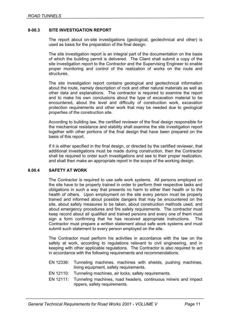
8-00.3 SITE INVESTIGATION REPORT
The report about on-site investigations (geological, geotechnical and other) is used as basis for the preparation of the final design.
The site investigation report is an integral part of the documentation on the basis of which the building permit is delivered. The Client shall submit a copy of the site investigation report to the Contractor and the Supervising Engineer to enable proper monitoring and control of the realization of works on the route and structures.
The site investigation report contains geological and geotechnical information about the route, namely description of rock and other natural materials as well as other data and explanations. The contractor is required to examine the report and to make his own conclusions about the type of excavation material to be encountered, about the level and difficulty of construction work, excavation protection requirements and other work that may be needed due to geological properties of the construction site.
According to building law, the certified reviewer of the final design responsible for the mechanical resistance and stability shall examine the site investigation report together with other portions of the final design that have been prepared on the basis of this report.
If it is either specified in the final design, or directed by the certified reviewer, that additional investigations must be made during construction, then the Contractor shall be required to order such investigations and see to their proper realization, and shall then make an appropriate report in the scope of the working design.
8.00.4 SAFETY AT WORK
The Contractor is required to use safe work systems. All persons employed on the site have to be properly trained in order to perform their respective tasks and obligations in such a way that presents no harm to either their health or to the health of others. Upon employment on the site every person must be properly trained and informed about possible dangers that may be encountered on the site, about safety measures to be taken, about construction methods used, and about emergency procedures and fire safety requirements. The contractor must keep record about all qualified and trained persons and every one of them must sign a form confirming that he has received appropriate instructions. The Contractor must prepare a written statement about safe work systems and must submit such statement to every person employed on the site.
The Contractor must perform his activities in accordance with the law on the safety at work, according to regulations relevant to civil engineering, and in keeping with other applicable regulations. The Contractor is also required to act in accordance with the following requirements and recommendations:
EN 12336: Tunneling machines, machines with shields, pushing machines, lining equipment, safety requirements.
EN 12110: Tunneling machines, air locks, safety requirements. EN 12111: Tunneling machines, road headers, continuous miners and impact
rippers, safety requirements.
General Technical Requirements for Road Works 2001 - VOLUME V Page 11

ROAD TUNNELS
The Contractor must also act in accordance with the Client's practice relating to the safety at work, and in keeping with rules set by all competent authorities or bodies when their operation or property is put in danger due to realization of works. All safety-related training and training about procedures to be followed in critical situations must also include appropriate practical exercises.
The Contractor must nominate a safety official that must be well acquainted with company's policies, administrative guidelines, regulations, legal provisions and codes of practice, and with the way in which the health and safety will be influenced by the application of such provisions. The Contractor, his management and every individual, regardless of his position in the organization, shall be responsible for the harmonization with the health and safety requirements.
The Contractor is required to provide on the construction site:
1. first aid facilities with properly trained personnel, both on the ground surface and under the ground surface, as required by the works,
2. equipment for rescuing and evacuating people working under the ground level, and personnel properly trained to use such equipment,
3. all equipment, safety fences, warning signs etc. as necessary for the protection of personnel,
4. appropriate fire fighting equipment, 5. chemical or compressed oxygen in first-aid kits for people working under the
ground level, 6. safety official who is properly informed about hazards related to the
construction method used on the project, and is responsible for the implementation of all instructions, rules and regulations prescribed by the administration with respect to the safety at work,
7. depending on legal requirements and requirements specified by the Client, as well as on the size and type of works, the Contractor may nominate a safety official as mentioned under item 6 who will perform his duties on the construction site from time to time. This official will come to the site at the beginning of works and in case the method of work is modified, but in any case the time interval between his successive visits to the site shall not exceed one month.
The Supervising Engineer shall be consulted regarding all proposals that are connected with the safety on the construction site. Nevertheless, this consultation shall not relieve the Contractor of his legal obligations or those specified in the contract. The Contractor must also make sure that:
1. the construction site and machines are in good condition, 2. the construction site is protected against any unauthorized entry of children, 3. the lighting in adits and tunnels is in accordance with applicable
recommendations. Stand-by tunnel lighting must also be secured. The on-site lighting must not be detrimental to areas outside of the site.
Site visitors have to be instructed about the work that is carried out at the time of their visit and must be informed about any danger that may be encountered. During every visit, visitors must be accompanied by a person nominated for such visits.
General Technical Requirements for Road Works 2001 - VOLUME V Page 12
ROAD TUNNELS
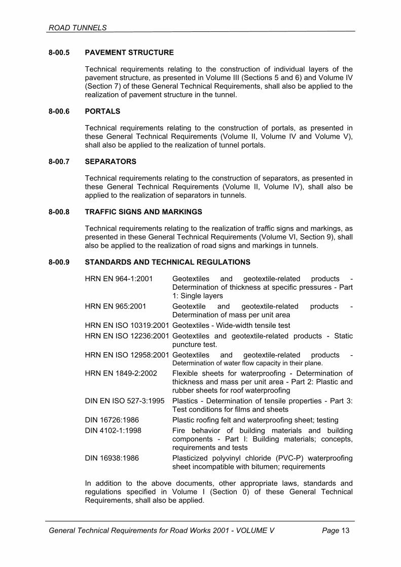
8-00.5 PAVEMENT STRUCTURE
Technical requirements relating to the construction of individual layers of the pavement structure, as presented in Volume III (Sections 5 and 6) and Volume IV (Section 7) of these General Technical Requirements, shall also be applied to the realization of pavement structure in the tunnel.
8-00.6 PORTALS
Technical requirements relating to the construction of portals, as presented in these General Technical Requirements (Volume II, Volume IV and Volume V), shall also be applied to the realization of tunnel portals.
8-00.7 SEPARATORS
Technical requirements relating to the construction of separators, as presented in these General Technical Requirements (Volume II, Volume IV), shall also be applied to the realization of separators in tunnels.
8-00.8 TRAFFIC SIGNS AND MARKINGS
Technical requirements relating to the realization of traffic signs and markings, as presented in these General Technical Requirements (Volume VI, Section 9), shall also be applied to the realization of road signs and markings in tunnels.
8-00.9 STANDARDS AND TECHNICAL REGULATIONS
HRN EN 964-1:2001 Geotextiles and geotextile-related products - Determination of thickness at specific pressures - Part 1: Single layers
HRN EN 965:2001 Geotextile and geotextile-related products - Determination of mass per unit area
HRN EN ISO 10319:2001 Geotextiles - Wide-width tensile test HRN EN ISO 12236:2001 Geotextiles and geotextile-related products - Static
puncture test. HRN EN ISO 12958:2001 Geotextiles and geotextile-related products -
Determination of water flow capacity in their plane. HRN EN 1849-2:2002 Flexible sheets for waterproofing - Determination of
thickness and mass per unit area - Part 2: Plastic and rubber sheets for roof waterproofing
DIN EN ISO 527-3:1995 Plastics - Determination of tensile properties - Part 3: Test conditions for films and sheets
DIN 16726:1986 Plastic roofing felt and waterproofing sheet; testing DIN 4102-1:1998 Fire behavior of building materials and building
components - Part I: Building materials; concepts, requirements and tests
DIN 16938:1986 Plasticized polyvinyl chloride (PVC-P) waterproofing sheet incompatible with bitumen; requirements
In addition to the above documents, other appropriate laws, standards and regulations specified in Volume I (Section 0) of these General Technical Requirements, shall also be applied.
General Technical Requirements for Road Works 2001 - VOLUME V Page 13
ROAD TUNNELS
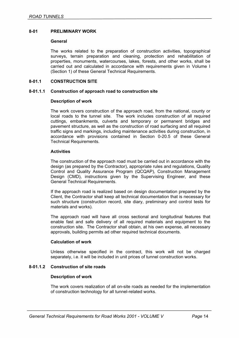
8-01 PRELIMINARY WORK
General
The works related to the preparation of construction activities, topographical surveys, terrain preparation and cleaning, protection and rehabilitation of properties, monuments, watercourses, lakes, forests, and other works, shall be carried out and calculated in accordance with requirements given in Volume I (Section 1) of these General Technical Requirements.
8-01.1 CONSTRUCTION SITE
8-01.1.1 Construction of approach road to construction site
Description of work
The work covers construction of the approach road, from the national, county or local roads to the tunnel site. The work includes construction of all required cuttings, embankments, culverts and temporary or permanent bridges and pavement structure, as well as the construction of road surfacing and all required traffic signs and markings, including maintenance activities during construction, in accordance with provisions contained in Section 0-20.5 of these General Technical Requirements.
Activities
The construction of the approach road must be carried out in accordance with the design (as prepared by the Contractor), appropriate rules and regulations, Quality Control and Quality Assurance Program (QCQAP), Construction Management Design (CMD), instructions given by the Supervising Engineer, and these General Technical Requirements.
If the approach road is realized based on design documentation prepared by the Client, the Contractor shall keep all technical documentation that is necessary for such structure (construction record, site diary, preliminary and control tests for materials and works).
The approach road will have all cross sectional and longitudinal features that enable fast and safe delivery of all required materials and equipment to the construction site. The Contractor shall obtain, at his own expense, all necessary approvals, building permits ad other required technical documents.
Calculation of work
Unless otherwise specified in the contract, this work will not be charged separately, i.e. it will be included in unit prices of tunnel construction works.
8-01.1.2 Construction of site roads
Description of work
The work covers realization of all on-site roads as needed for the implementation of construction technology for all tunnel-related works.
General Technical Requirements for Road Works 2001 - VOLUME V Page 14

ROAD TUNNELS
Activities
Site roads are dependant on the construction technology selected, on the configuration of the terrain and the construction management design (CMD). They are realized by the Contractor as temporary facilities and maintained by the Contractor throughout the realization of the works. These road mainly connect places where construction work is realized with production plants (crushing plant, screening plant, concrete plant, depot of explosive substances, depot of construction materials, laboratory and offices for project manager, supervision staff and Contractor's administration building). The quality level of the pavement structure and surfacing shall be selected by the Contractor depending on construction costs and time needed to complete all tunnel-related works.
Calculation of work
This work will not be paid for separately, i.e. the corresponding costs will be included, together with maintenance during construction, in contract items for payment of tunneling works.
8-01.1.3 Erection of storage depot for explosive substances
Description of work
The work covers erection of the storage depot, temporary depots or transportable storage units (containers) which are assembled in order to store, protect and keep explosive substances during construction, as well as disassembly of these facilities and reinstatement of the terrain after the end of construction including, if necessary, appropriate repairs.
Activities
The construction of storage depot for explosive substances implies realization of storage area with one or several facilities for the storage, protection and maintenance of explosive substances to be used in blasting operations during excavation of the tunnel and cuttings.
These facilities may be:
• Masonry storage facility for storing over 5000 kg of explosive substances, separately from ignition devices (detonators) and watchman booth,
• transportable storage facility (container) made of metal and destined for storing and keeping up to 5000 kg of explosive substances and 5000 detonators,
• stand-by storage is a room where up to 20 kg of explosive substances can be stored and kept.
The building and operating permit delivered by a competent authority must be obtained for all storages to be installed on the site. Such facilities shall be installed at a safe distance from other structures, as specified in appropriate regulations, in natural valleys and on locations where they will not disturb realization of either road construction or tunneling works.
General Technical Requirements for Road Works 2001 - VOLUME V Page 15
Storages must be protected in such a way to prevent access of unauthorized persons. This is done by constant physical and technical protection. Storages must also be compliant with special construction requirements relating to

ROAD TUNNELS
protection against fire and explosives, and must also meet other applicable regulations.
All potential dangers that may occur during realization of the project must be solved by the Contractor in the scope of the Construction Management Design (CMD) and construction technology. He must also place all required warning signs and prohibitive signs in accordance with applicable regulations.
Lightning installations must be placed on all structures, and the properly fenced-off storage depot, including the watchman booth, shall be lighted during the night.
Calculation of work
The work related to the construction of the storage depot for explosive substances shall not be paid for separately, as this cost is deemed included in pay items and unit rates provided in the contract.
8-01.1.4 Construction of compressor station and air-duct distribution system
Description of work
The work covers purchase, delivery and assembly of compressor devices at the tunnel portal zone, distribution of air ducts along the tunnel as the work progresses, and disassembly of such devices and their removal from the site.
Fabrication
Based on the tunneling technology selected, the Contractor shall purchase, deliver to the site and assemble compressor devices in accordance with compressed air requirements, and shall realize the on-site duct system. In addition to compressor assembly, he shall also realize appropriate sheds, and shall build approaches for truck cranes and fuel-supply tank trucks.
Detailed technical data with characteristics of the devices and their distribution shall be presented in the Construction Management Design (CMD).
Calculation of work
The work related to the compressor unit assembly and realization of the duct system shall not be paid for separately, as this cost is deemed included in pay items and unit rates provided in the contract.
8-01.1.5 High voltage connection and transformer station
Description of work
The work covers connection to the existing high voltage transmission line either by air or cable, and installation of an appropriate number of transformer stations, depending on the tunnel length.
Activities
High voltage connections shall be realized in accordance with the Construction Management Design (CMD) and requirements set by the competent electric utility, using services of the contractor duly specialized for this type of work. All
General Technical Requirements for Road Works 2001 - VOLUME V Page 16
ROAD TUNNELS
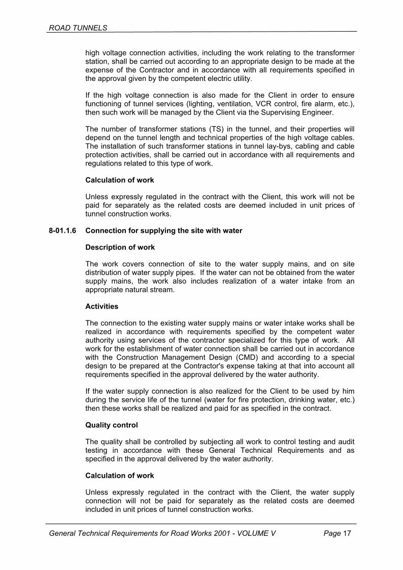
high voltage connection activities, including the work relating to the transformer station, shall be carried out according to an appropriate design to be made at the expense of the Contractor and in accordance with all requirements specified in the approval given by the competent electric utility.
If the high voltage connection is also made for the Client in order to ensure functioning of tunnel services (lighting, ventilation, VCR control, fire alarm, etc.), then such work will be managed by the Client via the Supervising Engineer.
The number of transformer stations (TS) in the tunnel, and their properties will depend on the tunnel length and technical properties of the high voltage cables. The installation of such transformer stations in tunnel lay-bys, cabling and cable protection activities, shall be carried out in accordance with all requirements and regulations related to this type of work.
Calculation of work
Unless expressly regulated in the contract with the Client, this work will not be paid for separately as the related costs are deemed included in unit prices of tunnel construction works.
8-01.1.6 Connection for supplying the site with water
Description of work
The work covers connection of site to the water supply mains, and on site distribution of water supply pipes. If the water can not be obtained from the water supply mains, the work also includes realization of a water intake from an appropriate natural stream.
Activities
The connection to the existing water supply mains or water intake works shall be realized in accordance with requirements specified by the competent water authority using services of the contractor specialized for this type of work. All work for the establishment of water connection shall be carried out in accordance with the Construction Management Design (CMD) and according to a special design to be prepared at the Contractor's expense taking at that into account all requirements specified in the approval delivered by the water authority.
If the water supply connection is also realized for the Client to be used by him during the service life of the tunnel (water for fire protection, drinking water, etc.) then these works shall be realized and paid for as specified in the contract.
Quality control
The quality shall be controlled by subjecting all work to control testing and audit testing in accordance with these General Technical Requirements and as specified in the approval delivered by the water authority.
Calculation of work
Unless expressly regulated in the contract with the Client, the water supply connection will not be paid for separately as the related costs are deemed included in unit prices of tunnel construction works.
General Technical Requirements for Road Works 2001 - VOLUME V Page 17
ROAD TUNNELS
8-01.1.7 Disposal of excavated material and evacuation of water from the tunnel
Description of work
The work covers disposal of excavated material and evacuation of water from the tunnel, management of disposal area, handling of usable material, and realization of required structures in portal zones for the purification of water evacuated from the tunnel.
Activities
Material obtained by excavation from the tunnel can be:
• unusable waste material, • usable mixed material for embankments, • usable clean and good quality stone material.
Unusable waste material is the earth material completely or excessively saturated with water, that is not suitable for further use, and has to be transported to the permanent place of disposal as specified in the design or as directed by the Supervising Engineer. The mixed material (stone-earth mix) that is not highly significant shall be placed onto a disposal site or shall be built into road embankments without prior stockpiling. For such use of this material, the Contractor has to make necessary tests and obtain evidence on the acceptability of such material, which evidence shall be submitted (in original copy) to the Supervising Engineer.
The clean and good-quality stone material shall be placed to a special disposal site where it will be subjected to additional treatment and recrushing so that it can be used as stone material for the base course of pavement structures or as a stone aggregate fraction for concrete and asphalt works. The Contractor is required to obtain, at the very beginning of tunnel excavation, an appropriate document attesting to the acceptability of such clean stone material and shall submit an original copy of such document to the Supervising Engineer.
Regardless of the Contractor's need for these materials, he shall classify them based on their usability and place them to specified areas. If disposal sites for usable material are situated at the distance exceeding that specified in the design, the Supervising Engineer shall approve to the Contractor longer distance of transport for such materials. Requirements for the use of these usable materials shall be defined in the contract concluded between the Contractor and the Client, and shall be regulated by protocol during construction.
The evacuation of waste and torrential waters from the tunnel most be performed in the controlled manner, i.e. by forming appropriate water intake and cleaning installations in front of portals, in accordance with the approval of the competent authority. A detailed description of the water purification devices and installations is given in Section 8-01.2.3.
Calculation of work
The work shall be calculated per in place bank cubic meter of stockpiled material. The work shall not be paid for separately as it is included in unit rates for excavation for the distances of up to 1500 m.
General Technical Requirements for Road Works 2001 - VOLUME V Page 18
ROAD TUNNELS
8-01.1.8 Other
In addition to plants and facilities specified in Section 8-01.2, the Contractor may also erect other facilities such as:
• booster pumping system, • covered storage, • open storage for construction materials, • oxygen storage, • carpenter and iron working plant, • fuel supply station, • machine loading ramp, • heavy-machinery parking area, • settling tank next to concrete plant, • sports grounds for recreation, • main entrance gate.
Calculation of work
The works shall be calculated and paid for separately as they are included in the total cost of construction work.
8-01.2 WORKING ENVIRONMENT
8-01.2.1 General
The Contractor shall define layout of the construction site in accordance with provisions contained in these General Technical Requirements. The Contractor shall organize site work is such a way that his temporary buildings, plants, equipment, etc. do not disturb permanent works on the road, road tunnel and other structures.
The Contractor shall organize the site in accordance with the technology he plans to use and is required to equip the site with his own technology and at his own expense. The Contractor is also required to organize approach roads and the transport of materials to the place of use.
The Contractor is required to obtain all permits relating to the construction work. Such permits may be:
• approval from the electric energy distributor for the supply of electric power to the site,
• permit for the establishment of connection to the existing water supply mains, • sanitary permit for the evacuation of industrial (waste) water from the tunnel, • all other permits and approvals as necessary for the realization of works.
In case construction work is interrupted for reason of force majeure, or if such interruption is directed by the Supervising Engineer, the Contractor will be responsible for the safety on construction site throughout such interruption of work. The contractor shall remove all his temporary structures that were erected for the realization of works and shall restore all areas as required.
General Technical Requirements for Road Works 2001 - VOLUME V Page 19
ROAD TUNNELS
8-01.2.2 Submittal of documents
The Contractor shall submit to the Supervising Engineer copies of all permits he had to obtain with respect to the construction, such as:
• approval from the electric energy distributor for the supply of electric power to the site,
• permit for the establishment of connection to the existing water supply mains, • sanitary permit for the evacuation of industrial (waste) water from the tunnel, • all other permits and approvals as necessary for the realization of works.
The ventilation system shall be subject to the approval of the Supervising Engineer. The contractor's proposal must include (but shall not be limited to) information about the ventilator type, distribution of ventilators (when possible), power supply and ventilator capacity data, as well as information about properties of the installation duct (ventilation pipe).
The Contractor must prepare the gas and pollutant testing plan, with the frequency of testing and test methods he plans to use, and shall submit this plan to the approval of the Supervising Engineer.
The Supervising Engineer's approval must also be obtained for the Contractor's plan for the operation of traffic outside of the construction site area. This plan must contain traffic safety measures he plans to apply, including safety zones and traffic signs. The plan must also contain requirements for the access of emergency services to the site and for the passage of such services through the site.
All proposals, details, construction works, maintenance, removal and reinstatement activities relating to traffic safety and operation of traffic, as well as temporary bridge structures, installation of slabs, and other temporary structures or underpasses, shall be subject to the approval of competent institutions. The Contractor must gather all information as necessary for the consultation with competent institutions, such as local authorities, police department services and other competent bodies or interested parties.
8-01.2.3 Realization
Temporary electrical installations
The installations must comply with EN 60204 and appropriate Croatian standards (HRN). The Contractor shall appoint a person that will be responsible for the safety of these temporary electrical installations on the construction site. The Contractor must act in accordance with the Occupational Safety Act and other laws and regulations.
Ventilation system during construction
The tunnel, pits, shafts and adits shall be properly ventilated throughout the excavation so as to create conditions favorable for the safe work, free of potentially hazardous or explosive gases, dust, and to avoid lack of oxygen. The Contractor must take appropriate measures to enable safe and efficient performance of works. In all his activities, the Contractor must act in accordance with Croatian occupational safety regulations. In underground and closed spaces
General Technical Requirements for Road Works 2001 - VOLUME V Page 20
ROAD TUNNELS
the inhaled air must not have less than 19 percent of oxygen per unit volume. Smoking is strictly forbidden in tunnels, pits, shafts, adits and in all confined spaces.
If the forced ventilation system is used, the ventilators shall be placed outside of the tunnel. An undisturbed supply of fresh air must be provided for every such ventilator. It must not be placed in the vicinity of oil tanks, storage with chemicals, or fuel barrels. The ventilator must be positioned in such a way that it does not suck in gases generated by vehicles, vapor or gases appearing during battery charging processes, or other impurities coming out of the tunnel.
The condition of air must be tested every time the ventilator is switched on or off, i.e. before the employees are allowed to enter into the tunnel. If forced ventilation is the only system used, it must be restarted and allowed to work continuously so that any accumulation of air, deficient in oxygen or containing inflammable or gaseous mixtures, can be blown out. Every precaution must be taken so that the workers entering the tunnel do not encounter accumulations of such harmful gases. The Contractor must take into account the fact that the time needed for ventilation of long tunnels may vary from one half an hour to several hours and that gas layers of differing density are difficult to eliminate particularly in zones where tunnel inclination changes. In cases when dust is created during tunnel excavation, the ventilation system must be able to rapidly remove dust from the working zone.
When longer tunnels are built, i.e. in cases when rapid natural ventilation is not possible, the excavation may only be allowed if a safe ventilation system has been established.
Bottom sections of all shafts, pits and deep trenches must be ventilated by means of an exhaust ventilation system.
The equipment that is used to perform measurements in tunnel must be suitable for continuous measurement of the level of explosive and harmful gases and for determination of the oxygen content. The equipment must have sound and visual signals that are activated when explosive or noxious gases are identified and when oxygen level is below the level considered safe for workers. A direct and efficient signaling device must be placed on the ground surface, i.e. at tunnel portals.
At the beginning of each shift, every shaft used, as well as the entire length of the tunnel, must be inspected for the presence of explosive or noxious gases and for the lack of oxygen. If at the heading the level of explosive or noxious gases is above the allowable level or if the quantity of oxygen is below the allowable level, all activities will be stopped and employees will be evacuated from the tunnel. The work will be resumed only after safe working conditions have been reestablished.
The activation procedure must be applied if for any reason the ventilation system has not been in operation for more than two hours. In such cases the personnel is not allowed to enter the tunnel or shaft until the entire air has been replaced. Persons that need to enter the tunnel after the ventilation system has been shut down must carry with them instruments for the detection of noxious gases and for measurement of oxygen content. These instruments must be activated every time such persons enter the tunnel.
General Technical Requirements for Road Works 2001 - VOLUME V Page 21
ROAD TUNNELS
The following verifications shall be made during every shift:
(a) Fan or fans are checked for overheating, unusual noise and vibrations. Results must be reported and repair measures, if necessary, must be undertaken without delay.
(b) Ventilation ducts and connections are checked for damage. Results must be reported and repair measures, if necessary, must be undertaken without delay.
(c) Monitoring system shall be checked at local and remote stations and results shall be recorded if necessary.
Once a week, the rate of air exchange shall be checked at the heading and 20 m away from the shaft bottom. These measurements shall be recorded and compared with planned air exchange data. All deficiencies shall be promptly rectified. The ventilation records shall be kept and shall be subject to the approval of the Supervising Engineer.
If the ventilation equipment breaks down, the personnel must be evacuated from the underground posts and, if the tunnel boring machine is used, the machine shall be promptly switched off and isolated until the ventilation is reinstated.
If the oxygen level is below 19 percent, no access to the underground site will be allowed except for saving lives and then only to persons equipped with appropriate protective clothing and equipment.
Site lighting
The lighting with spotlights must be of such quality that it ensures safe realization of works. When necessary the light can be shaded so that it is directed to specific zones only and to avoid eye irritation. The tunnel lighting must be provided for the entire length and its intensity shall not be lower than that required for the safe work and access, i.e. it shall amount to at least 100 watts per every 10 meters of the tunnel length.
An alternative source of energy and the back up lighting system must be available in case of emergency so as to enable implementation of necessary measures and safe evacuation if the primary source of power supply is interrupted. In addition, a sufficient number of flashlights must be readily available at key points in the tunnel.
Protection against noise and vibrations
Noise and vibration levels must comply with the Occupational Safety Act and with other applicable rules and regulations.
The Contractor must select and use work methods, plants and devices in such a way to reduce the level of noise and vibration, including professional noise and exposure to vibration at work, and is in any case required to keep the level of noise and vibrations within maximum allowable levels.
Compliance with vibration requirements specified in these General Technical Requirements does not liberate the Contractor from his obligations with respect to damage inflicted on an another structure or property.
General Technical Requirements for Road Works 2001 - VOLUME V Page 22

ROAD TUNNELS
When necessary, the Contractor shall erect during construction a temporary fence of adequate height, and this fence shall at the same time be a sound barrier aimed at diminishing noise generated at working areas. The fence shall be dismantled and reassembled as necessary in keeping with the progress of the works. The fence line must be uniform and the external side of the fence shall be protected with permanent coating. When necessary the Contractor shall, in order to prevent reflection of noise, line the internal side of the fence with appropriate noise diminishing material.
The material must be resistant to the action of water and fire. Local fences and sheds shall be erected when necessary to protect specific activities, i.e. when pneumatic or hydraulic work techniques are used and at stationary plants.
The Contractor shall supply and use environmentally friendly low-noise equipment, compliant with requirements for the safe and efficient realization of the work. The equipment most be designed in such a way that the noise and vibrations generated during operation are reduced to a minimum.
The equipment must be properly maintained and appropriate servicing records must be kept. The equipment must have adequate silencers and vibration damping devices which must be used in accordance with the manufacturer's recommendations in order to avoid excessive levels of noise and vibrations.
When measurement of noise and vibration is necessary, the Contractor has to supply equipment for the measurement of noise an vibrations during the entire time of construction, and shall calibrate and operate such equipment in accordance with the manufacturer's specifications. Vibration measuring systems must be compliant with relevant standards.
The Contractor is required to measure levels of noise and vibrations caused by construction during working hours, and this throughout the time of construction. Each time the specified level of noise or vibration is exceeded the Contractor shall immediately advise the Supervising Engineer about such occurrence and shall agree with him preventive measures to be taken. All portions of the equipment or plant that cause excessive levels of damage or vibration shall be removed from the site and replaced with an appropriate alternative equipment. The Supervising Engineer may advise the Contractor to establish and use an alternative process if the method used during construction causes unnecessary disturbance.
Traffic in tunnel and on site
The Contractor must ensure safe approach to the site and around it as well as to the site in the tunnel. The Contractor must provide for the permanent pedestrian access to the tunnel. This access must have a hard, even and continuous surface that is not slippery and that can conveniently be used in emergencies, i.e. when no lighting is available. The Contractor is required to provide at all times an appropriate means of evacuation from every heading in the tunnel. Dimensions of such means of evacuation (except for tunnel boring machines, trains and similar machines) must be compliant with minimum dimensions specified in EN 12336.
Final excavation levels (final grade levels) for the construction of pavement structure shall be protected against wear or degradation due to site transport operations by placing rock aggregate excavated in the tunnel or similar
General Technical Requirements for Road Works 2001 - VOLUME V Page 23
ROAD TUNNELS
aggregate, at least 0,5 m in thickness. Accumulation of water in depressions and transport through any accumulation of water shall not be permitted. All material rendered unsuitable by transport activities shall be removed and replaced before the work on the pavement structure starts, and this replacement shall be carried out as directed by the Supervising Engineer. The backfill material used for this protection shall not be removed until immediately prior to realization of the pavement structure.
No traffic shall be allowed on unprotected, concrete or shotcrete, temporary of final, surfaces of the tunnel invert. The structure as such will be protected against damage by backfill material obtained from tunnel excavation or from similar source, and this material will be placed no less than 0.5 meters in thickness.
The backfill material shall not contain aggregate grains of more than 150 mm in diameter.
Disposal of waste material from the tunnel
The Contractor shall remove all unsuitable or excess excavated material, as well as any debris from any source within the construction site, and shall discharge such material at an appropriate location and shall, in addition, perform all that is needed for such disposal, in full accordance with applicable regulations. The Contractor must also act in accordance with regulations related to the disposal and handling of contaminated waste materials.
The Contractor shall define, in concert with the Supervising Engineer, a detailed program of activities for the removal of waste material. The Contractor must organize an appropriate system for the monitoring and supervision of transport of waste material from to site to the disposal area, in full accordance with applicable regulations. The system shall be subject to the approval of the Supervising Engineer, and an evidence must be submitted that the entire waste material was actually discharged at an appropriate disposal site.
The Contractor must act in accordance with all regulations and legal provisions relating to the disposal of waste material.
The Contractor must obtain approval from competent authorities before proceeding to disposal of liquid waste.
Water evacuation in tunnel during construction
The Contractor shall supply, install, put into operation and maintain a sufficient number of pumps and pipes, in order to enable proper control and evacuation of water from any part of the underground site. No accumulation or presence of water in the tunnel shall be permitted. The capacity of pumps installed at every heading shall at all times be at least one and half times higher than the nominal water inflow plus the quantity of water required for rinsing the drilling equipment. The Contractor will have at his storage, or keep ready for use, stand-by pumps which must be in good operating condition, and their capacity must be equal or greater than that of pumps installed in the tunnel.
The Contractor shall be required to obtain purification devices or other appropriate devices for the decontamination, as required by the Supervising Engineer, before allowing discharge of purified water into the surrounding terrain.
General Technical Requirements for Road Works 2001 - VOLUME V Page 24
ROAD TUNNELS
The Contractor shall remove all accumulated sludge, sediments and other material remaining after completion of underground works, as directed by the Supervising Engineer. The Contractor shall install, maintain and keep in operation all necessary devices and plants as needed for the preparation and treatment of polluted water to be discharged at tunnel portals during realization of tunneling works. Such devices and plants shall consist of two sedimentation basins, a light liquid separator (oil trap), a neutralization device and appropriate inspection stations. The neutralization device shall be assembled and put into operation in order to keep the pH value of the purified water between 6.5 and 8.5 prior to discharge.
During realization of works, the tunnel drainage shall be operated by means of ditches. If necessary, the trenches shall be rendered impermeable by means of shotcrete. In the areas of high water inflow, it might be necessary to install drainage pipe made of hard PVC or structured high-density polyethylene (HDPE) ranging from 150 to 250 mm in size, depending on the quantity of water to be evacuated.
In case the rock mass is highly susceptible to water action, the Contractor shall pay maximum attention to the accumulation and drainage of seepage water and the water needed in drilling operations. In case of descending adits, intercepting pits will be realized in regular intervals and the water will be evacuated from such pits by means of steel high-density polyethylene (HDPE) or PVC pipes.
In moist portions of the rock, the water is collected in pipe halves (preferably soft undulating polyethylene or PVC pipes) which are fixed to the rock by quick-setting mortar or shotcrete, and the water is then evacuated to intercepting pits or longitudinal trenches.
Pipes at least 4 cm in diameter shall systematically be placed, as directed by the Supervising Engineer, in tunnels realized in permeable soil or highly porous rock, in order to avoid increase in water pressure behind the shotcrete lining.
The Contractor shall keep the intercepting pits clean and shall maintain the drainage system in such a way that the water inflow and seepage is properly controlled throughout the period of construction.
8-01.2.4 Calculation of work and payment
The works specified in this section shall be calculated as follows:
• The work related to the placing of temporary electrical and lighting installations shall not be calculated separately. All such costs shall be included in unit prices for total tunnel construction works and this throughout the period of tunnel construction.
• The work relating to the supply of water to the site shall not be calculated separately. All such costs shall be included in unit prices for the total works, unless otherwise specified in the contract.
• The work related to the establishment of the ventilation system during tunnel construction shall not be calculated separately. All such costs shall be included in unit prices for total tunnel construction works and this throughout the period of tunnel construction.
• The costs related to the protection against noise and vibration shall not be calculated separately. All such costs shall be included in unit prices for total
General Technical Requirements for Road Works 2001 - VOLUME V Page 25
ROAD TUNNELS
tunnel construction works and this throughout the period of tunnel construction.
• The costs related to activities aimed at enable traffic in tunnel shall not be calculated separately. All such costs shall be included in unit prices for total tunnel construction works and this throughout the period of tunnel construction.
• The costs of evacuation of water during construction shall be calculated in the scope of tunnel excavation in the manner as specified in the section Tunnel excavation and in the section Drainage of these General Technical Requirements.
• The costs related to the disposal of waste material from the tunnel shall not be calculated separately. All such costs shall be included in unit prices for total tunnel construction works and this throughout the period of tunnel construction.
8-01.3 CONSTRUCTION OF APPROACH CUTTINGS
Description of work
The work covers realization of preliminary and earth works on the road route, in the length of the approach cutting, until the entrance and exit portals of the tunnel, all in accordance with Volume I (Section 1), Volume II (Sections 2 and 3) and Volume V of these General Technical Requirements.
Calculation of work
All work related to the approach cutting shall be calculated and paid for based on the special cost estimate given in the contract, all in accordance with Volume II (Section 2) of these General Technical Requirements for road works.
8-01.3.1 Protection of the face of the approach cutting
Description of work
The work covers protection of the face of approach cuttings at the entrance and exit portals of the tunnel, in the entire width and height, as specified in the design.
Activities
After excavation for the approach cutting or during this excavation (in case of deep cuttings) the face of the approach cutting may need to be protected if the natural soil is unstable.
Rock bolts, reinforcing steel and shotcrete shall be placed using methods similar to those used for the tunnel excavation support. If outside temperatures are above 20°C or below 0°C, additional measures will have to be taken to ensure that the quality of shotcrete is appropriate (shotcrete cure, and protection measures for winter time shotcreting).
If the tunnel excavation is to commence by blasting, then additional support by 4-6 m long rock bolts, reinforcing steel and shotcrete, shall be placed at the face of the approach cutting, along the periphery of the cross section, outside of the line specified in the contract.
General Technical Requirements for Road Works 2001 - VOLUME V Page 26
ROAD TUNNELS
Quality control
The quality shall be checked by control testing and audit testing to be carried out for all construction work items in the manner specified in these General Technical Requirements.
Calculation of work
The work shall be calculated in accordance with appropriate cost estimate items, in the manner similar to that used for the protection of tunnel excavation. The price shall include all work and material necessary for this type of work, unless otherwise specified in the contract.
8-01.4 STANDARDS AND TECHNICAL REGULATIONS
ENV 1991 Bases for design and actions on structures. ENV 1992 Design of concrete structures. ENV 1997 Geotechnical design. EN 12336 Tunnel boring machines - shielded tunnel boring machines, machines
for boring by pushing action, lining equipment - safety requirements. EN 815 Safety criteria for unshielded tunnel boring machines and rock drilling
machines. EN 12110 Tunneling machines, air locks, safety requirements. EN 12111 Tunneling machines, road headers, continuous miners and impact
rippers, safety requirements. EN 60204 Electrical installations.
Other relevant laws, standards and regulations given in Volume I (Sections 0 and I) of these General Technical Requirements shall also be applied.
8-02 TUNNEL EXCAVATION
8-02.0 GENERAL PROVISIONS
This section covers realization of all underground works related to tunnel excavation in any type of rock or soil.
The Contractor is required to act in accordance with all provisions specified in design documents and drawings, and as described in General Technical Requirements and in documents to be submitted in relation to the working design or contract, as approved by the Supervising Engineer.
The Contractor shall perform all excavation and support work in the manner compliant with excavation support requirements for a particular tunnel category, and shall reduce to minimum any disintegration and loosening of the rock mass around the excavation, so as to limit overbreak and prevent damage to already placed lining.
Stages of excavation and cross-section excavation plan shall be defined in accordance with the design, these General Technical Requirements, and according to drawings contained in the working design which will be produced by the Contractor in accordance with the actual condition of rock as established during tunnel excavation.
General Technical Requirements for Road Works 2001 - VOLUME V Page 27

ROAD TUNNELS
The Contractor shall be responsible for the selection of an appropriate equipment and may propose an alternative excavation method, unless otherwise specified in other documents.
The station of the designed route corresponding to natural soil (or rock) at the tunnel crown shall be taken as the limit dividing outside excavation (approach cutting) from the excavation in tunnel.
8-02.0.1 Classification of excavation work
The following topics are discussed in this section: classification of rock mass during tunnel excavation, characteristic description of individual rock mass classes, general measures for the excavation and stabilization of underground excavations, and limits of responsibilities of individual participants in the construction process.
The rock mass shall be classified in accordance with the geomechanical classification (Bieniawski, 1979). This classification is used during realization of road tunnels in rock by drilling and blasting or by mechanical excavation in the underground. The method is not applied during excavation of tunnels in soil or for tunnels realized by the cut and cover method.
Basic procedure
The rock mass classification is based on results obtained by engineering geological mapping of the tunnel. Engineering geological mapping of the excavated part of the tunnel must be performed after each advancement. All relevant parameters needed for rock mass classification must be identified in the scope of such engineering geological mapping. Results of engineering geological mapping of the tunnel are presented on the expanded tunnel profile and submitted in that form to the Supervising Engineer.
The engineering geological mapping of the tunnel shall be performed by the Contractor. The Contractor is required to enable the Supervising Engineer to perform audit mapping of individual tunnel sections without asking for special compensation. This includes provision of lighting at the excavated section and clear marking of tunnel stations at every 50 m. The tunnel mapping must not affect realization of works in the tunnel.
Based on engineering geological mapping and inspection of the heading, the Supervising Engineer shall perform rock mass classification according to geomechanical criteria, and shall define the rock mass class as well as measures to be used for the excavation and support, as specified in the design for the said rock mass class. The classification needs to be carried out only in case of significant change of geological and geotechnical properties of the rock mass along to tunnel route, i.e. such classification is not necessary after each advancement.
In order to perform rock mass classification, the Supervising Engineer has to be specialized in the area of underground geotechnical structures or he must have in the supervision team an assistant specialized for the underground geotechnical structures.
If the Contractor should object to the classification results, the matter will finally be settled in the course of an arbitration procedure. However the work will
General Technical Requirements for Road Works 2001 - VOLUME V Page 28
ROAD TUNNELS
continue based on the Supervising Engineer's decision until the final decision is reached for the dispute. The cost of arbitration procedure shall be borne by the Contractor.
Regardless of decisions made by the Supervising Engineer and geotechnical designer, the Contractor shall be solely responsible for the safety of works performed in the tunnel.
If the Contractor detects any signs of instability in the tunnel, or if the underground excavation behaves in the manner that is not compliant with assumptions given in the geotechnical design, then the Contractor shall promptly inform the Designer and the Supervising Engineer about such events, and the latter two will determine the causes and modify measures specified in the design with respect to the excavation and stabilization of the underground opening.
Results obtained by engineering geological survey and rock mass classification shall be presented on specially prepared forms to be specified by the Supervising Engineer prior to the commencement of work. These forms will be an integral part of the design documentation. In addition, an actual engineering geological profile of the tunnel must also be prepared. It shall include information about rock mass classification and about support systems used in the tunnel.
Description of the rock mass classification
The geomechanical classification is based on the point system in which six rock mass parameters are analyzed:
• uniaxial compressive strength of rock material, • RQD - rock quality designation, • spacing of joints • condition and quality of joints and discontinuities, • condition of groundwater, • orientation of joints or discontinuities.
The distribution of rock mass parameters according to individual values and the point allocation scheme are presented in Tables 8-02-1, 8-02-2 and 8-02-3. The sum of points according to Table 8-02-4 determines the rock mass class. In addition to these tables, the enclosed diagrams can also be used for a more accurate allocation of points (Bieniawski, 1989).
The analysis and determination of classification parameters must be conducted in accordance with appropriate ISRM recommendations. At that, average values of parameters, rather than the worst ones, must be taken into account because the classification is based on already realized projects, and hence implicitly contains a factor of safety.
The uniaxial compressive strength of rock material is determined on an intact rock sample by standard laboratory testing, based on recommendations given by the International Society for Rock Mechanics (Suggested Methods for Determining the Uniaxial Compressive Strength and Deformability or Rock Materials, ISRM 1979).
General Technical Requirements for Road Works 2001 - VOLUME V Page 29

ROAD TUNNELS
Although points for the uniaxial compressive strength of rock material may be obtained based on Table 8-02-1, a more accurate system is presented in diagram given in Figure 8-02-1 (Bieniawski, 1989).
The Supervising Engineer shall select rock material samples for uniaxial strength testing in laboratory if he considers that the strength of rock material in the excavation significantly deviates from values given in the geotechnical design.
RQD (Rock Quality Designation) is a linear indicator of soundness of the rock mass. It is obtained by drilling, and it is actually a relationship between the sum of lengths of all drilled cores longer than 10 cm, and the total length drilled, and is expressed as a percentage.
ISRM recommendations (Suggested Methods for the Quantitative Description of Discontinuities in Rock Masses, ISRM 1978) must be respected during determination of the RQD parameter.
In underground excavations, the RQD can be determined based on the total number of discontinuities contained in unit volume of rock mass according to an approximate correlation (Palmström, 1982):
RQD = 115 - 3.3 Jv
where:
Jv = sum of joints per unit length for all joint sets.
Table 8-02-2 The effect of strike and dip on tunneling
Strike perpendicular to tunnel axis Excavation in the
direction of the spreading of discontinuities
Excavation in the direction opposite to the
spreading of discontinuities
Strike parallel to tunnel axis
regardless of orientation
Dip 45° - 90°
Dip 20° - 45°
Dip 45° - 90°
Dip 20° - 45°
Dip 20° - 45°
Dip 45° - 90°
Dip 0° - 20°
Very favorable
Favorable Fair Unfavorable Fair Very unfavorable
Fair
Table 8-02-3 Correction of points for the effect of strike and dip
Strike and dip of discontinuities
Very favorable
Favorable Fair Unfavorable Very unfavorable
Points Tunnels 0 -2 -5 -10 -12
Table 8-02-4 Rock mass classes determined from total ratings
Rating (RMR) 100-81 80-61 60-41 40-21 <20 Class I II III IV V
Rock mass description
Very good
Good Fair Poor Very poor
General Technical Requirements for Road Works 2001 - VOLUME V Page 30
ROAD TUNNELS
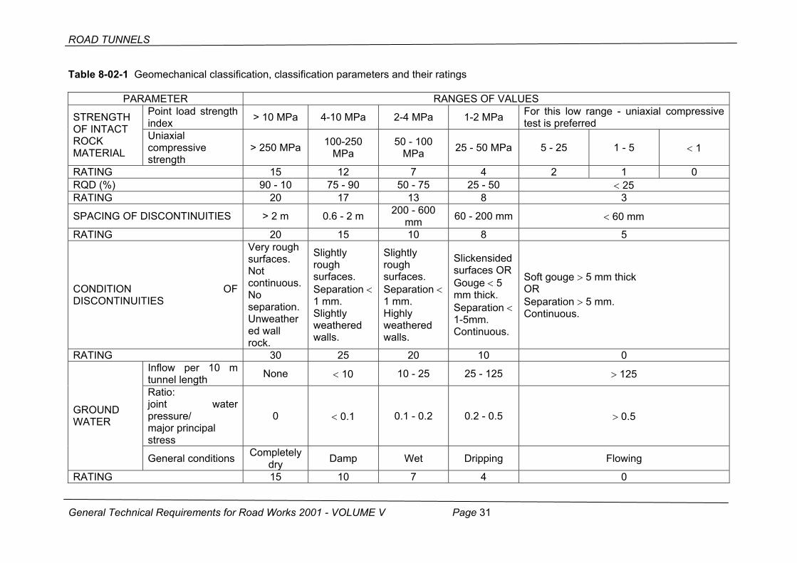
Table 8-02-1 Geomechanical classification, classification parameters and their ratings
PARAMETER RANGES OF VALUESPoint load strength index > 10 MPa 4-10 MPa 2-4 MPa 1-2 MPa For this low range - uniaxial compressive
test is preferred STRENGTH OF INTACT ROCK MATERIAL
Uniaxial compressive strength
> 250 MPa 100-250 MPa
50 - 100 MPa 25 - 50 MPa 5 - 25 1 - 5 < 1
RATING 15 12 7 4 2 1 0RQD (%) 90 - 10 75 - 90 50 - 75 25 - 50 < 25 RATING 20 17 13 8 3
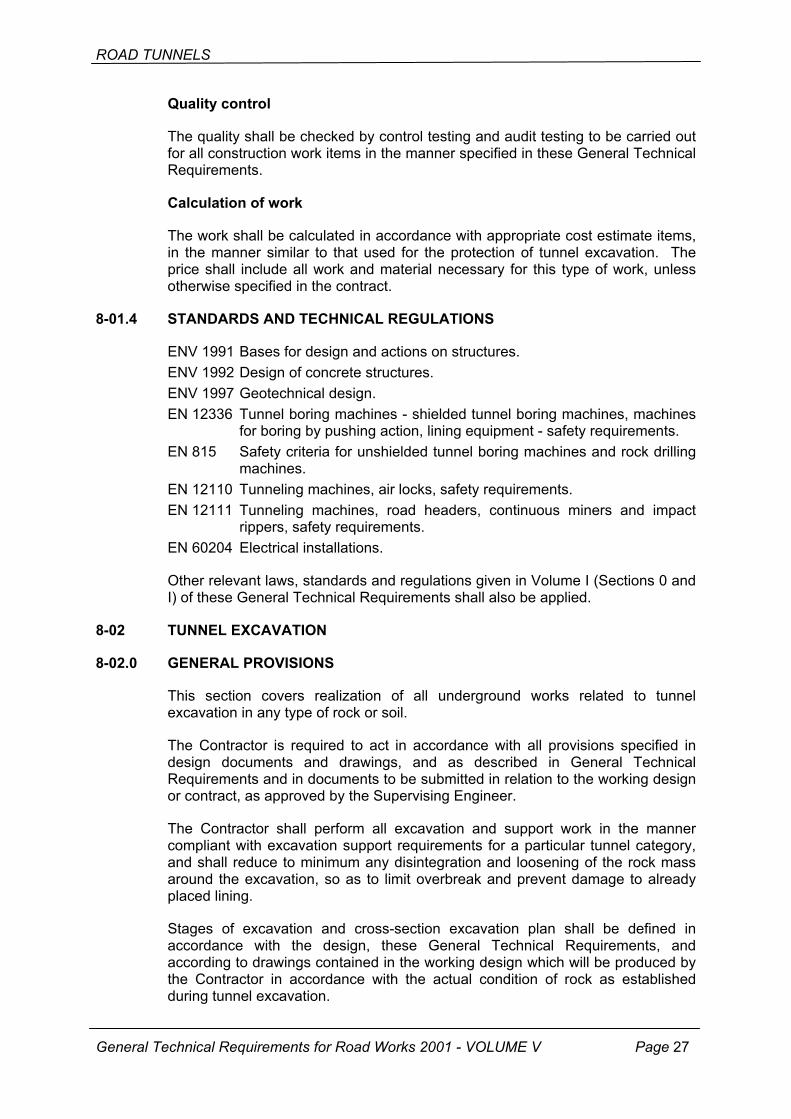
SPACING OF DISCONTINUITIES > 2 m 0.6 - 2 m 200 - 600 mm 60 - 200 mm < 60 mm
RATING 20 15 10 8 5
CONDITION OFDISCONTINUITIES
Very rough surfaces. Not continuous. No separation. Unweathered wall rock.
Slightly rough surfaces. Separation < 1 mm. Slightly weathered walls.
Slightly rough surfaces. Separation < 1 mm. Highly weathered walls.
Slickensided surfaces OR Gouge < 5 mm thick. Separation < 1-5mm. Continuous.
Soft gouge > 5 mm thick OR Separation > 5 mm. Continuous.
RATING 30 25 20 10 0Inflow per 10 m tunnel length None < 10 10 - 25 25 - 125 > 125
Ratio: joint water pressure/ major principal stress
0 < 0.1 0.1 - 0.2 0.2 - 0.5 > 0.5 GROUND WATER
General conditions Completely dry Damp Wet Dripping Flowing
RATING 15 10 7 4 0
General Technical Requirements for Road Works 2001 - VOLUME V Page 31

ROAD TUNNELS
In addition to Table 8-02-1, RQD points may also be defined, albeit more accurately, using diagram presented in Figure 8-02-2 (Bieniawski, 1989).
00
I
]40 80 120 160 200 240
1
2
3
4
5
6
7
8
9
10
11
12
13
14
15
BOD
OV
PO
INTS
UNIAXIAL COMPRESSIVE STRENGTH
JEDNOAKSIJALNA TLACNA CVRSTOCA [MPaUNIAXIAL COMPRESSIVE STRENGTH (MPa)
Figure 8-02-1 Points allocated for the strength of rock material
0 20 40 60 80 1000
2
4
6
8
12
14
16
18
20
RQD [%]
10
BO
DO
VI
PO
INTS
Figure 8-02-2 Points allocated for the RQD
Spacing of joints (discontinuities) is determined by measuring with the measuring strip perpendicular to discontinuities, on a sample ten times as big as the estimated spacing. When defining the parameter "spacing of discontinuities" it is important to respect appropriate ISRM recommendations (Suggested Methods for the Quantitative Description of Discontinuities in Rock Masses, ISRM 1978).
General Technical Requirements for Road Works 2001 - VOLUME V Page 32
ROAD TUNNELS
00
I
A [mm]
2
4
6
8
10
12
14
16
18
20
4 1600 2000
BO
DO
VP
OIN
TS
S S
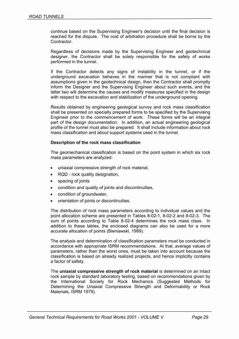
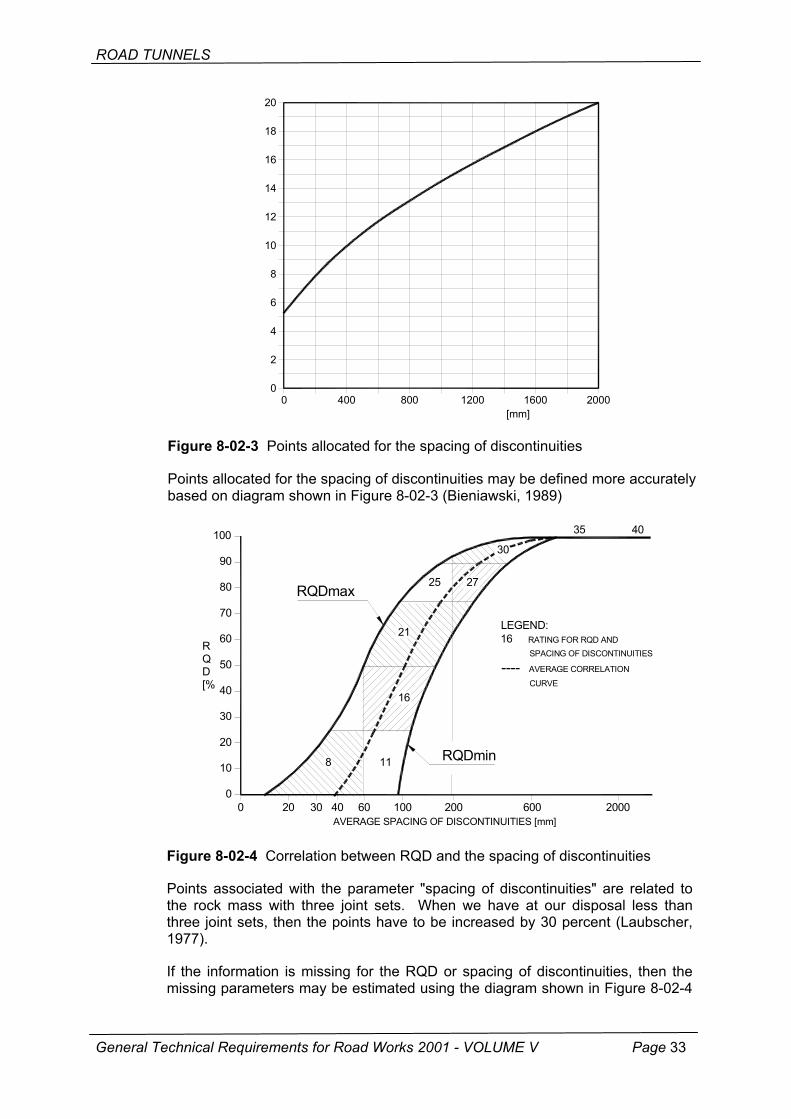
Figure 8-02-3 Points alloc
Points allocated for the spabased on diagram shown in
0
RQD [%
A
0
10
20
30
40
50
60
70
80
90
100
20 30 40
RQDm
8
Figure 8-02-4 Correlation
Points associated with thethe rock mass with three three joint sets, then the p1977).
If the information is missinmissing parameters may b
General Technical Requirements for R
MAK DISKONTINUITET00 800 1200
RAZPACING OF DISCONTINUITIE
ated for the spacing of discontinuities
cing of discontinuities may be defined more accurately Figure 8-02-3 (Bieniawski, 1989)
VERAGE SPACING OF DISCONTINUITIES [mm] 60 100 200 600 2000
ax
RQDmin 11
16
21
25 27
30
35 40
LEGEND:
16 RATING FOR RQD AND SPACING OF DISCONTINUITIES
---- AVERAGE CORRELATION
CURVE
between RQD and the spacing of discontinuities
parameter "spacing of discontinuities" are related to joint sets. When we have at our disposal less than oints have to be increased by 30 percent (Laubscher,
g for the RQD or spacing of discontinuities, then the e estimated using the diagram shown in Figure 8-02-4
oad Works 2001 - VOLUME V Page 33
ROAD TUNNELS
(Bieniawski, 1989) which was derived from correlational data (Priest, Hudson, 1976).
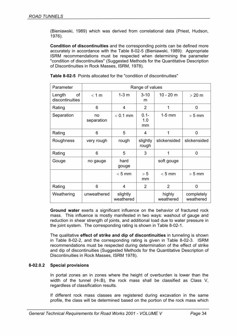
Condition of discontinuities and the corresponding points can be defined more accurately in accordance with the Table 8-02-5 (Bieniawski, 1989): Appropriate ISRM recommendations must be respected when determining the parameter "condition of discontinuities" (Suggested Methods for the Quantitative Description of Discontinuities in Rock Masses, ISRM, 1978).
Table 8-02-5 Points allocated for the "condition of discontinuities"
Parameter Range of values
Length of discontinuities
< 1 m 1-3 m 3-10 m
10 - 20 m > 20 m
Rating 6 4 2 1 0
Separation no separation
< 0.1 mm 0.1-1.0 mm
1-5 mm > 5 mm
Rating 6 5 4 1 0
Roughness very rough rough slightly rough
slickensided slickensided
Rating 6 5 3 1 0
Gouge no gauge hard gouge
soft gouge
< 5 mm > 5 mm
< 5 mm > 5 mm
Rating 6 4 2 2 0
Weathering unweathered slightly weathered
highly weathered
completely weathered
Ground water exerts a significant influence on the behavior of fractured rock mass. This influence is mostly manifested in two ways: washout of gauge and reduction in shear strength of joints, and additional load due to water pressure in the joint system. The corresponding rating is shown in Table 8-02-1.
The qualitative effect of strike and dip of discontinuities in tunneling is shown in Table 8-02-2, and the corresponding rating is given in Table 8-02-3. ISRM recommendations must be respected during determination of the effect of strike and dip of discontinuities (Suggested Methods for the Quantitative Description of Discontinuities in Rock Masses, ISRM 1978).
8-02.0.2 Special provisions
In portal zones an in zones where the height of overburden is lower than the width of the tunnel (H<B), the rock mass shall be classified as Class V, regardless of classification results.
If different rock mass classes are registered during excavation in the same profile, the class will be determined based on the portion of the rock mass which
General Technical Requirements for Road Works 2001 - VOLUME V Page 34
ROAD TUNNELS
bears a decisive influence on the stability of the overall excavation, i.e. on the support work requirements. In most cases, this will be the rock mass in the crown of the tunnel.
The class allocated to the excavation of lay-bys and tunnel widenings, and to the excavation of cross cuts, shall be the same as that defined for the main cross section of the tunnel.
8-02.0.3 Working design
Throughout the duration of the works, the Contractor will have at his disposal a Design Consultant who will prepare for him additions to the working design, which will be subject to the approval of the Designer. All drawings will have to be submitted to the Supervising Engineer sufficiently in advance of construction (at least 14 days prior to construction), or as defined by mutual agreement.
Prior to commencement of any tunnel excavation, the Contractor shall submit for approval by the Supervising Engineer working drawings and/or description of the proposed method and stages of excavation, including excavation support measures, site drainage system, safety measures and test results.
Based on the rock classification system used, the Contractor shall submit to the Supervising Engineer for approval a detailed plan showing work stages for excavation and support in every rock class and for every type of excavation profile, and the method of excavation in which the method, excavation procedure and transport modalities will be described.
All blasting activities shall be conducted in accordance with the blasting design and in keeping with national regulations relating to safety measures and precautions to be taken during handling of explosives, and also in accordance with these General Technical Requirements.
Prior to the planned use of explosives, the Contractor is required to inform the Supervising Engineer, third parties, competent authorities as well as services interested in such operations or likely to be influenced by them. The Contractor is required to inform the Supervising Engineer and other mentioned persons and services at least 14 days prior to the planned use of explosives.
The blasting design shall be submitted to the Supervising Engineer for every type of cross section or part of cross section, and shall contain the following information:
• blasting model, blast hole diameter, distance, depth and inclination; • type, strength, quantity (weight) and charges of explosive to be used in each
individual blast hole, in every sequence and the total value for each blasting cycle;
• distribution of load in blast holes and first charge in each blast hole; • type, sequence and number of delays, delay pattern, wiring diagram for
blasting, size and type of fastened lines and lead lines; type and capacity of ignition sources; type of blasting machine with condensate discharge;
• strengthening/protection of blast holes and blast hole covering or the entire zone covering;
General Technical Requirements for Road Works 2001 - VOLUME V Page 35
• written evidence about qualifications of persons that will be directly responsible for the supervision of charging and blasting operations.

ROAD TUNNELS
The blaster must record the number of shots, timing of shots, type and weight of explosives used, and the type and number of detonators, and shall also include in this record description of the condition registered at every location after blasting operations. He is required to submit a copy of such record to the Supervising Engineer at the end of each shift in which blasting operations were performed.
The material excavated in the tunnel shall be transported to the location specified in the design or to a disposal site, unless otherwise directed by the Supervising Engineer.
Before any material is transported to the disposal site, the Contractor shall submit to the Supervising Engineer for approval his proposal about the location of the planned disposal site and disposal area, unless specified in the design. This proposal will contain all relevant information about the disposal site, description of work methods, description and calculation of stability, provisions about safety, and plans for the temporary and permanent drainage, and also the proposal for the restoration of the terrain.
8-02.0.4 Realization
Definition of excavation profile
The excavation profile specified in the design drawings is referred to as the design excavation profile which is defined as line T (cf. Figure 8-02-5).
Overbreak
I line
T line
Figure 8-02-5 Deformational and construction tolerances and overbreak due to unfavorable geological conditions
General Technical Requirements for Road Works 2001 - VOLUME V Page 36

ROAD TUNNELS
Depending on the rock mass quality, appropriate widening will be made to leave sufficient space for radial deformations (Td) and construction tolerances (Tk).
The excavation profile, defined as I line (cf. Figure 8-02-5), is the theoretical profile for the compensation of radial deformation for different rock mass classes, which takes into account the possibility of deformation (Td).
Experience-based deformation values given in design documents must be adjusted to actual deformation values registered during tunnel excavation. Adjustments will be made on behalf of the Contractor by the Design Consultant, after which such proposed adjustments will be submitted to the Supervising Engineer for approval.
I line stands for the smallest excavation profile. In general, the rock will not protrude within this line at the time of excavation.
The Contractor shall make best efforts to keep the profile within limits defined by I line and this by carefully monitoring the drilling process and by using various elements of smooth blasting or pre-splitting.
In order to keep the profile in harmony with I line, the Contractor will have to take into account the construction tolerance (Tk) for the excavation and support work. The construction tolerance (Tk) also covers measurement imperfections.
Overbreak
Overbreak is the space created after the tunnel is excavated beyond the design profile, including deformational and construction tolerances. This beyond-the-profile excavation may be caused by inadequate realization and negligent excavation (which may be avoided) and/or is due to reasons that can not be influenced by the Contractor (which can not be avoided, i.e. admissible overbreak).
Such admissible overbreak can be caused by:
• natural fallout that can not be avoided by careful work and appropriate realization,
• extremely unfavorable and/or unpredictable geological conditions.
The overbreak and fallout can be considered admissible if the Contractor, despite his best efforts and the best possible realization of the work, can not prevent overbreak because of dominantly unfavorable geological conditions, so that the excavation exceeds the limit lines defined in the design for a particular class of rock.
If such overbreak occurs, the support must be placed without delay in order to stabilize the soil. The Supervising Engineer must promptly be advised of any such occurrence. The Contractor and the Supervising Engineer shall jointly examine and define measures to improve the situation.
The detailed drawing for such improvement shall be made by the Contractor/Design Consultant and shall then be submitted to the Supervising Engineer for approval. The overbreak improvement work shall be carried out before proceeding to any further work at the heading, unless otherwise approved or directed by the Supervising Engineer.
General Technical Requirements for Road Works 2001 - VOLUME V Page 37
ROAD TUNNELS
Once it is established that physical conditions that caused the overbreak were beyond the control of the Contractor, and that the overbreak is not due to improper work or negligence, the space created by such overbreak will be measured at the place of excavation. The material necessary for this improvement/repair shall then be quantified and the document with such quantification shall be submitted to the Supervising Engineer for approval and payment purposes.
The temporary protection of the excavation, which is placed by the Contractor to protect people and equipment, and which is not a structural part of the initial support, will not be calculated, as it forms a part of protection measures that the Contractor is obliged to take.
All occurrences of overbreak and fallout, and all caverns or caves, regardless of whether they are due to geologically admissible reasons or to the Contractor's fault, must be surveyed in full detail, in perpendicular and longitudinal directions, and this before and after the improvement work. Each survey must be accompanied with the improvement proposal and bill of quantities showing the quantity of overbreak and the volume of fallouts or caverns, as well as the quantity and type of material used for the improvement.
Equipment
All mechanical plant and equipment used in tunnel excavation and mucking activities must be of design suitable for such activities and must comply with applicable Croatian safety regulations. It must also meet requirements given in progress schedules which are submitted to the Supervising Engineer for approval.
The mechanical plant and equipment used in tunnel excavation shall be powered by electricity, compressed air or diesel fuel. Diesel engines must be equipped with scrubbers for the purification of exhaust gases. Gasoline or paraffin powered devices shall not be used in tunnel excavation. Rock drilling accompanied by rinsing with water shall not be allowed in rock formations susceptible to water action, unless this is required by soil conditions, and even then if approved by the Supervising Engineer.
Verification of tunnel axis by topographic surveying
The Contractor must have at the tunnel site a topographic survey team throughout the time of tunnel construction. This team must be equipped with modern surveying instruments, appropriate equipment allowing measurement in dark confined spaces, with an appropriate transport device. The topographic survey team is required to determine and check levels and lines of all excavated segments of the tunnel.
The Client shall submit to the Contractor, through the intermediary of the Supervising Engineer, a topographic base report for all tunnels of more that 200 m in length, and all numerical information and drawings for proper guidance of tunnel excavation and construction of individual tunnel elements.
The Client shall submit to the Contractor, through the intermediary of the Supervising Engineer and by means of an appropriate protocol, properly laid and stabilized permanent topographic points at tunnel portals will appropriate
General Technical Requirements for Road Works 2001 - VOLUME V Page 38
ROAD TUNNELS
description of positions, their coordinates and levels within the national measurement system.
The Contractor is required to preserve these permanent topographic points from damage throughout the time of tunnel construction. In case of damage, or if additional points are needed, the Contractor shall inform the Supervising Engineer that the repair or relocation of such points is required. The cost of this work shall be borne by the Contractor.
During the tunnel tube excavation activities, the Contractor shall stabilize permanent point at every 500 m in accordance with topographic rules and shall protect them from damage. These permanent points will be used for verification surveys of tunnel axis as made for the Client and as a means of controlling excavation of the tunnel tube.
Whenever possible, permanent points shall not be placed at spots where the bottom part of excavation is unstable or susceptible to displacement due to some special geological conditions.
From time to time, the Client shall control, through the intermediary of the Supervising Engineer, these stabilized permanent control points (marks). The Contractor is required to allow the topographic survey team from the supervision service to perform surveys at a time defined in advance, in which case the work in the tunnel will be interrupted and the tunnel will additionally be ventilated to reduce dust content in the air.
The Contractor is required to allow this survey team to inspect and use all survey records made by the Contractor.
Verification survey data and results obtained by analysis of these data are relevant for the continuation of work and shall be added to the tunnel construction technical documents as special reports produced after every verification survey.
Topographic surveying of excavation work
In his surveying activities, the Contractor must use appropriate topographic instruments and electronic distance meters, as well as special devices for the infrared or laser-based measurement of tunnel excavation profiles (profiler).
The excavated profile shall be surveyed, if practicable, after every advance step but at least one measurement shall be made for every 10 m of excavation, to enable correction of blast hole positions.
Measurements will be performed by the Contractor's topographic survey team immediately after excavation at the periphery of rock surface in the tunnel opening or at the first shotcrete layer in case of favorable rock classes (1, 2 and 3).
If the rock mass belongs to the tunneling class 4 or 5, the measurements will be made after the full completion of the initial support and after the distance has been measured by hand along the periphery of steel arches at every 2.0 m from the internal top of the steel arch to the natural soil at the contour of the excavation.
General Technical Requirements for Road Works 2001 - VOLUME V Page 39
ROAD TUNNELS
Such measured surface of excavation shall be added to that measured at the finally completed initial support.
Verification surveys conducted by the supervision team are carried out at the rate of 1 : 3 when compared to the surveys carried out by the Contractor. Verification surveys will be conducted using topographic survey instruments.
All topographic surveys shall also be presented in graphical form on the scale to be determined by the supervision team and stall regularly be submitted to the Supervising Engineer for inspection.
The tunnel axis shall be set out within an accuracy of plus or minus 1.0 cm.
Blast holes placed at the periphery shall be positioned within an accuracy of plus or minus 3.0 cm.
Topographic surveys of excavation and admissible fallouts shall be conducted within an accuracy of plus or minus 3.0 cm.
If the excavation is performed with rotary cutting in full profile (i.e. with the tunnel boring machine) then an automatic laser guidance of the machine must be ensured with a continuous control of the topographic line and permanent points in the tunnel tube.
Every admissible overbreak must duly be proven and confirmed by topographical measurements, and also approved by the Supervising Engineer.
Every inadmissible overbreak must duly be proven and confirmed by topographical measurements, and also approved by the Supervising Engineer.
The Contractor must ensure that the minimum profile of the final lining complies with that shown in design drawings.
The Contractor may propose the use of a more advanced topographic survey technique for the final excavation profile surveying.
The bottom level of excavation or the bottom of the invert shall be realized within an accuracy of plus or minus 5.0 cm in relation to theoretical excavation levels.
If, after removal of inappropriate material or sludge, the bottom excavation level is by more than 5 cm lower than the design level, the contractor will be required to fill, at his own expense, this overbreak with a good quality material normally used for the bottom base course of pavement structures, or with concrete all the way up to the theoretical level, or as directed and approved by the Supervising Engineer.
8-02.1 EXCAVATION WORK
The selection of the excavation method, blasting technique and support system will be dependant on the class of the rock mass in which tunnel is excavated. The proportion of individual rock mass classes in the entire tunnel is predicted based on the prognostic geological profile. The increase or reduction of the proportion of individual rock classes in tunnel excavation with respect to such proportions predicted in the design, shall not authorize the Contractor to modify
General Technical Requirements for Road Works 2001 - VOLUME V Page 40
ROAD TUNNELS
contract unit prices for excavation, although this may constitute the grounds for either extension or reduction of excavation time.
If a rock belonging to several excavation classes is encountered during tunnel excavation, the property of the rock in the arch of the excavation shall be decisive for the selection of excavation class, and it will be used as basis for selecting the excavation method and for defining protection of the overall profile.
The boring and blasting will be performed in such a way to ensure that the rock breaks along the desired lines. The Contractor is required to realize, without claiming any special recompense, a trial blasting section for every rock class in order to select the most efficient tunnel excavation method and to modify predicted blasting parameters.
The diameter and spacing of boreholes shall be adjusted to actual on site conditions. The Contractor shall develop and continuously improve blasting techniques as the tunneling work progresses, in order to obtain the best possible excavation surface after the blasting.
Modern blasting methods shall be used for the excavation in rock material. Controlled blasting methods, such as smooth blasting or presplitting, shall be used to reduce overbreak to minimum, and to prevent fragmentation of the rock surface.
Blasting operations will be permitted only after appropriate precautions have been taken to protect all persons, works and property. Blasting notices must be placed all over the site. Prior to every firing, the Contractor must give an oral warning to clear the area, and must take all necessary measures to prevent entry to the dangerous zone.
Openings shall not be filled before completion of drilling operations. No person shall be allowed access to the drilling zone, and no drilling shall be allowed to commence before an approval is given by the person authorized by the Contractor to perform the drilling.
Blasting operations will be carried out under guidance of an experienced operator, and explosives will be handled by blasters only. The Contractor shall appoint a person that will be responsible for the safety of explosives.
Lay-bys in side walls of the tunnel (except lay-bys for parking) and cross cuts shall be realized after the primary tunnel lining has been placed.
The primary lining of side walls of the tunnel must be carefully cut along the profile of lay-bys or cross cuts, and the excavation will be made in such a way no to inflict any damage to the remaining portions of the support work.
Boring, blasting, excavation and shotcreting operations shall be carried out using appropriate methods and equipment that enable proper control of dust, smoke, vapors, gases, fibers, fog and mist.
Tunnel excavation activities must be performed continuously unless otherwise approved by the Supervising Engineer. If the works so allow, tunneling activities may be interrupted during weekends and holidays, provided that works are properly protected during such interruptions.
General Technical Requirements for Road Works 2001 - VOLUME V Page 41
ROAD TUNNELS
No interruption shall be allowed prior to completion of all support elements for a particular class of rock material. Furthermore, the face of excavation will be protected with shotcrete (placed in an appropriate thickness), except in stable rock conditions, as approved by the Supervising Engineer.
The impact exerted on adjacent structures due to vibrations generated by blasting operations will be measured in the immediate vicinity of the structure closest to the heading or at some other location where the strength of vibration has to be limited. The peak particle velocity shall be measured by an appropriate instrument along three orthogonal axes. One of such axes must be parallel to the excavation axis, while an another one must be perpendicular to such axis. The peak particle velocity measurements shall be carried out by the Contractor. The list of values obtained during such measurement shall be submitted to the Supervising Engineer in a suitable form. The Contractor must prove by test blasts that specified peak particle velocities will not be exceeded. Test blasts shall be carried out at the beginning of blasting operations on every new location. Peak velocities must not exceed values specified for such velocities.
A characteristic description and usual behavior during excavation, as well as general measures to be taken during excavation and stabilization of underground excavations, will be presented for each rock mass category.
8-02.1.1 Rock mass class I
The rock mass class I is either a massive rock mass with less than three joint sets, or the rock mass with three sets of undulating, rough and closed joints, which do not allow fallout of blocks. This rock mass does not plasticize in the zone of underground excavation. Deformations are of the order of several millimeters and are realized during and immediately after excavation. Overbreak is negligible. Full face excavation at a maximum advance rate is possible. Generally, no support work is required except for occasional spot bolting.
8-02.1.2 Rock mass class II
The second rock class is the rock mass with three joint sets. Joints are slightly weathered at a spacing of more than 0.5 m. Generally, the rock mass will not plasticize in the zone of the underground excavation. Deformations are of the order of several millimeters and are realized during and immediately after excavation. Shallow blocks that may fall out during excavation will cause overbreak which will not be extensive.
Full face excavation at a maximum advance rate is possible.
The support work is necessary in the crown, and may be realized 20 m from the heading. Local occurrences of unstable blocks in the crown may be solved by individual bolting to be performed immediately after the excavation.
8-02.1.3 Rock mass class III
The third rock class is represented with the rock mass with three or more joint sets. Joints are weathered and are spaced at intervals ranging from 0.2 to 0.6 m. Generally the rock mass may locally be plasticized in a shallow zone around the underground excavation, depending on the initial state of stress. An average deformation is several millimeters in width, but settles rapidly after excavation and start of support work. The quantity of overbreak will depend on the local
General Technical Requirements for Road Works 2001 - VOLUME V Page 42
ROAD TUNNELS
orientation of discontinuities. Rock fallout and scaling, resulting in greater overbreak, can be expected during excavation.
The excavation in full profile is possible but the length of advance with depend on the local fallout of blocks. Up to 3 m advance rate is recommended.
The systemic crown and wall support will be conducted as necessary. The support work must commence by applying shotcrete immediately after excavation and the support work must end 10 m from the tunnel heading.
8-02.1.4 Rock mass class IV
The rock class IV is characterized by the completely fractured rock mass with fully weathered joints spaced at up to 0.2 m intervals. Generally the rock mass will be plasticized around the entire underground excavation. The depth of plasticization will depend on the initial state of stress. The deformation will not show tendencies to settle before the support work is placed. Significant fallout of material is possible in the period prior to the installation of the support system.
It is advisable to carry out excavation work in two stages, i.e. separately in the top and bottom halves of the tunnel. The allowable advance rate varies from 1 to 2 m depending on local conditions.
A systemic support of the crown and walls of the tunnel is required. The support must start immediately after excavation and end after the following advance and, in order to reach minimum rock mass quality requirements, the support work must be completed before the start of the next advance.
8-02.1.5 Rock mass class V
The rock class V is characterized by the completely disintegrated rock mass (fault zones). Generally, deeper zones of rock mass plasticization may be expected around the underground excavation. The deformation will not be likely to settle before the support work is placed and will amount to several centimeters on an average. There is no initial stability in the underground excavation so that steel bolts or steel sheets have to be driven prior to excavation. The overbreak will thus be reduced to minimum.
It is advisable to perform excavation work in three stages, i.e. in the top and bottom halves of the tunnel and in invert. In the first stage of excavation, the allowable advance rate will vary from 0.5 to 1 m.
The systematic support work in the crown and side walls must be performed, and the invert must be realized. The support work shall start immediately after excavation and the support must be completed before the next advance. In some instances, the excavation face must also be supported.
In this class of excavation, pressure measurements must be made in order to estimate stability of the underground opening in every stage of excavation and support work.
8-02.1.6 Overbreak
The overbreak is the space crate when the soil breaks beyond the design profile, including deformational and construction tolerances. This beyond-the-profile
General Technical Requirements for Road Works 2001 - VOLUME V Page 43
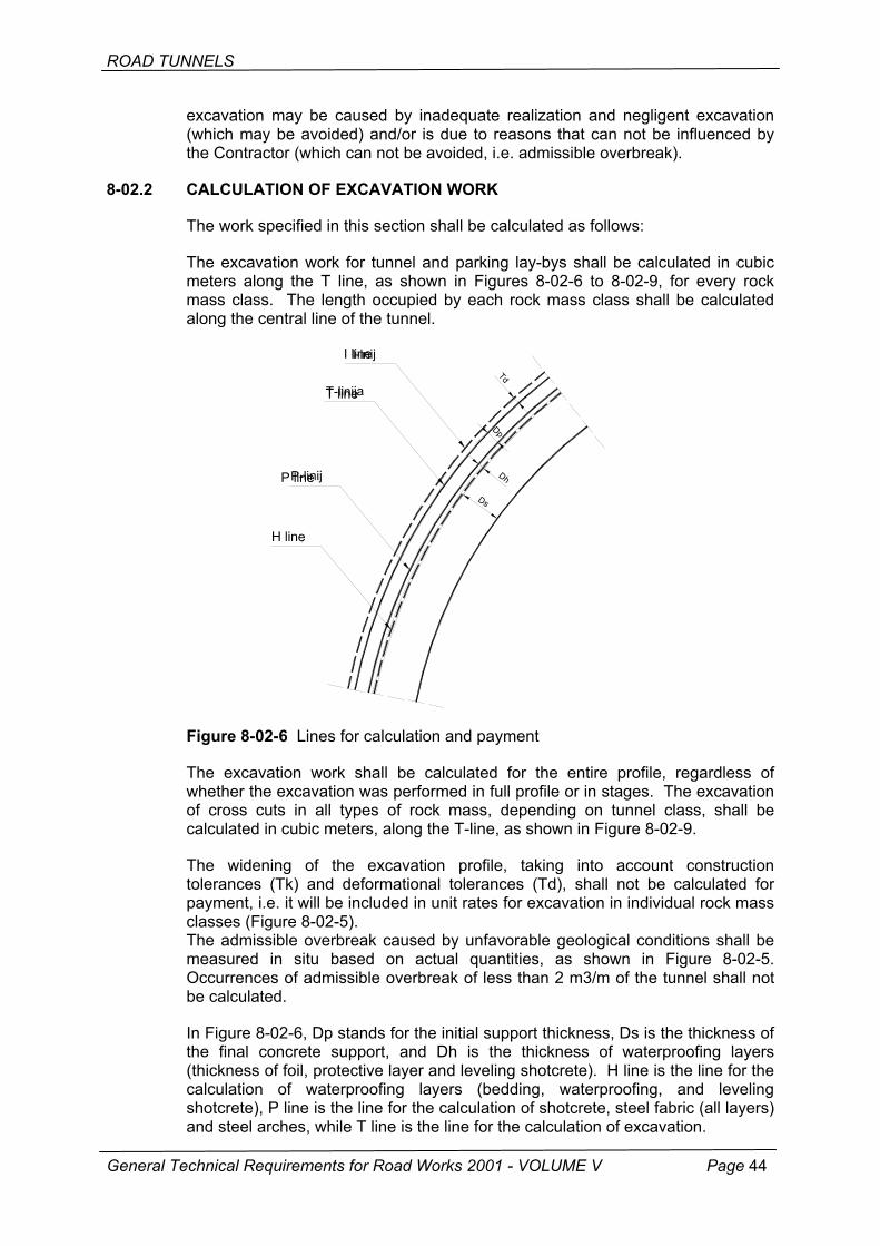
ROAD TUNNELS
excavation may be caused by inadequate realization and negligent excavation (which may be avoided) and/or is due to reasons that can not be influenced by the Contractor (which can not be avoided, i.e. admissible overbreak).
8-02.2 CALCULATION OF EXCAVATION WORK
The work specified in this section shall be calculated as follows:
The excavation work for tunnel and parking lay-bys shall be calculated in cubic meters along the T line, as shown in Figures 8-02-6 to 8-02-9, for every rock mass class. The length occupied by each rock mass class shall be calculated along the central line of the tunnel.
H ja
a
aije
nijP
H line
Figure 8-02-6 Lines f
The excavation workwhether the excavatioof cross cuts in all tcalculated in cubic me
The widening of thtolerances (Tk) and dpayment, i.e. it will be classes (Figure 8-02-5The admissible overbmeasured in situ baOccurrences of admisbe calculated.
General Technical Requirements
In Figure 8-02-6, Dp sthe final concrete su(thickness of foil, protecalculation of watershotcrete), P line is thand steel arches, while
I-inI lin
Td
ijae
T-linT linDh
Dp
P-li line
Ds-lini
or calculation and payment
shall be calculated for the entire profile, regardless of n was performed in full profile or in stages. The excavation ypes of rock mass, depending on tunnel class, shall be ters, along the T-line, as shown in Figure 8-02-9.
e excavation profile, taking into account construction eformational tolerances (Td), shall not be calculated for included in unit rates for excavation in individual rock mass ). reak caused by unfavorable geological conditions shall be sed on actual quantities, as shown in Figure 8-02-5. sible overbreak of less than 2 m3/m of the tunnel shall not
for Road Works 2001 - VOLUME V Page 44
tands for the initial support thickness, Ds is the thickness of pport, and Dh is the thickness of waterproofing layers ctive layer and leveling shotcrete). H line is the line for the proofing layers (bedding, waterproofing, and leveling e line for the calculation of shotcrete, steel fabric (all layers) T line is the line for the calculation of excavation.
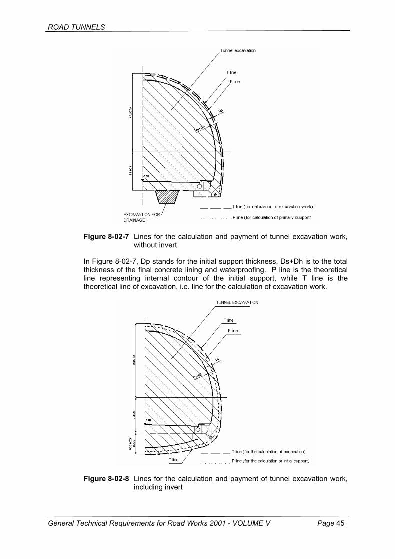
ROAD TUNNELS
Figure 8-02-7 Lines for the calculation and payment of tunnel excavation work, without invert
In Figure 8-02-7, Dp stands for the initial support thickness, Ds+Dh is to the total thickness of the final concrete lining and waterproofing. P line is the theoretical line representing internal contour of the initial support, while T line is the theoretical line of excavation, i.e. line for the calculation of excavation work.
Figure 8-02-8 Lines for the calculation and payment of tunnel excavation work, including invert
General Technical Requirements for Road Works 2001 - VOLUME V Page 45
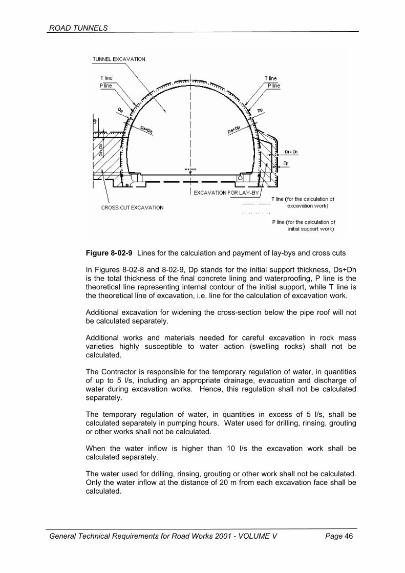
ROAD TUNNELS
Figure 8-02-9 Lines for the calculation and payment of lay-bys and cross cuts
In Figures 8-02-8 and 8-02-9, Dp stands for the initial support thickness, Ds+Dh is the total thickness of the final concrete lining and waterproofing, P line is the theoretical line representing internal contour of the initial support, while T line is the theoretical line of excavation, i.e. line for the calculation of excavation work.
Additional excavation for widening the cross-section below the pipe roof will not be calculated separately.
Additional works and materials needed for careful excavation in rock mass varieties highly susceptible to water action (swelling rocks) shall not be calculated.
The Contractor is responsible for the temporary regulation of water, in quantities of up to 5 l/s, including an appropriate drainage, evacuation and discharge of water during excavation works. Hence, this regulation shall not be calculated separately.
The temporary regulation of water, in quantities in excess of 5 l/s, shall be calculated separately in pumping hours. Water used for drilling, rinsing, grouting or other works shall not be calculated.
When the water inflow is higher than 10 l/s the excavation work shall be calculated separately.
The water used for drilling, rinsing, grouting or other work shall not be calculated. Only the water inflow at the distance of 20 m from each excavation face shall be calculated.
General Technical Requirements for Road Works 2001 - VOLUME V Page 46
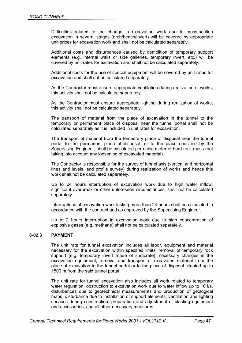
ROAD TUNNELS
Difficulties related to the change in excavation work due to cross-section excavation in several stages (arch/bench/invert) will be covered by appropriate unit prices for excavation work and shall not be calculated separately.
Additional costs and disturbances caused by demolition of temporary support elements (e.g. internal walls or side galleries, temporary invert, etc.) will be covered by unit rates for excavation and shall not be calculated separately.
Additional costs for the use of special equipment will be covered by unit rates for excavation and shall not be calculated separately.
As the Contractor must ensure appropriate ventilation during realization of works, this activity shall not be calculated separately.
As the Contractor must ensure appropriate lighting during realization of works, this activity shall not be calculated separately.
The transport of material from the place of excavation in the tunnel to the temporary or permanent place of disposal near the tunnel portal shall not be calculated separately as it is included in unit rates for excavation.
The transport of material from the temporary place of disposal near the tunnel portal to the permanent place of disposal, or to the place specified by the Supervising Engineer, shall be calculated per cubic meter of hard rock mass (not taking into account any loosening of excavated material).
The Contractor is responsible for the survey of tunnel axis (vertical and horizontal lines and levels, and profile survey) during realization of works and hence this work shall not be calculated separately.
Up to 24 hours interruption of excavation work due to high water inflow, significant overbreak or other unforeseen circumstances, shall not be calculated separately.
Interruptions of excavation work lasting more than 24 hours shall be calculated in accordance with the contract and as approved by the Supervising Engineer.
Up to 2 hours interruption in excavation work due to high concentration of explosive gases (e.g. methane) shall not be calculated separately.
8-02.3 PAYMENT
The unit rate for tunnel excavation includes all labor, equipment and material necessary for the excavation within specified limits, removal of temporary rock support (e.g. temporary invert made of shotcrete), necessary changes in the excavation equipment, removal and transport of excavated material from the place of excavation to the tunnel portal or to the place of disposal situated up to 1500 m from the said tunnel portal.
The unit rate for tunnel excavation also includes all work related to temporary water regulation, obstruction to excavation work due to water inflow up to 10 l/s, disturbances due to geotechnical measurements and production of geological maps, disturbance due to installation of support elements, ventilation and lighting services during construction, preparation and adjustment of blasting equipment and accessories, and all other necessary measures.
General Technical Requirements for Road Works 2001 - VOLUME V Page 47
ROAD TUNNELS
The disturbances and problems mentioned in the previous paragraph of these General Technical Requirements comprise:
• Tunnel excavation in individual rock mass classes shall be paid according to unit rates per cubic meter of excavation work.
• Excavation difficulties due to the presence of seepage water in quantities exceeding 10 l/s shall be paid for in unit rates per cubic mater of material excavated during such excessive water inflow.
• Temporary regulation of seepage water in quantities exceeding 5 l/s shall be paid for based on unit rates per hour of pumping. Unit rates for the temporary regulation of seepage water include all labor, equipment and material (such as pipes, intercepting pits) as needed for the realization of this work.
• Work interruption of more than 24 hours, due to excessive inflow of water, significant admissible overbreak or other unforeseen events, shall be paid for according to unit rates per hour of interruption. Such payment will be applicable only if blasters, accessory personnel and equipment used at the heading can not be transported to an another heading.
• Interruption of work in excess of 2 hours, due to inadmissibly high concentration of gases shall be paid for according to unit rates per hour of interruption. Such payment will be applicable only if blasters, accessory personnel and equipment used at the heading can not be transported to an another heading.
The unit price for excavation covers all labor, equipment and material needed for the monitoring and lowering concentration of gases during excavation work in the tunnel, as well as all necessary pilot drilling as needed for early detection of explosive gases (methane).
The unit price for offered excavation work shall not be dependant on the method actually used in tunnel excavation.
The unit price for the transport of excavated material to the location specified by the Supervising Engineer or to the place of disposal more than 1500 m away from the tunnel portal, includes all labor and equipment needed for the loading, transport and unloading of materials.
The loading and unloading of material at temporary places of disposal is also included in the unit price for transport.
The unit price for excavation is also applied for the local widening of cross section at temporary portals when this is necessary to increase thickness of the tunnel lining.
All labor, equipment and material needed for the purification and preparation of the polluted tunnel water prior to final discharge are included in the price for excavation and shall not be paid for separately.
8-02.3 STANDARDS AND TECHNICAL REGULATIONS
ENV 1991 Basis of design and actions on structures. ENV 1992 Design of concrete structures. ENV 1997 Geotechnical design.
General Technical Requirements for Road Works 2001 - VOLUME V Page 48
ROAD TUNNELS
EN 12336 Tunneling machines, machines with shields, pushing machines, lining equipment, safety requirements.
EN 815 Safety criteria for unshielded tunnel boring machines and rock drilling machines.
EN 12110 Tunneling machines, air locks, safety requirements. EN 12111 Tunneling machines, road headers, continuous miners and
impact rippers, safety requirements. EN 60204 Safety of machinery. Electrical equipment of machines. EN ISO/12236 Geotextiles and geotextile-related products. Static puncture test. EN ISO/16727 Plastic bituminized cloth and waterproofing layer; testing. EN ISO/16776 Plastic materials for molds, polyethylene materials for molds
(PE); preparation of components and determination of their properties.
EN ISO/53363 Plastic foil testing; tear test on trapezoidal samples with longitudinal slot.
EN ISO/53370 Plastic foil testing; determination of thickness by mechanical measurement.
EN ISO/53377 Thin plastic layer testing; determination of dimensional stability. EN ISO/53387 Artificial aging and aging of plastics and elastomers by exposure
to xenon arc radiation. EN ISO/53455 Plastics testing; strength testing. EN ISO/53457 Plastics testing; determination of elastic modulus by testing
strength, compression and bending. EN ISO/53479 Testing plastics and elastomers; determination of density. EN ISO/53488 Plastic foil testing, hole test. EN ISO/53515 Determination of the tear strength of rubber elastomers and thin
layers of plastics using Graves angle test piece with nick. EN ISO/53521 Determining behavior of rubber and elastomer when exposed to
the action of fluids and vapors. EN ISO/53532 Elastomer testing; determination of elastomeric plate resistance
to the action of fluids. EN ISO/53739 Plastics testing; influence of fungi and bacteria, visual inspection,
change in mass and physical properties. EN ISO/53861 Textile testing; reduction test and break test; definition of terms. ASTM 820 Standard requirements for reinforced-concrete steel fibers. ASTM A569 Steel plate for sliding disks. ASTM DI693 Chemical resistance. DIN 4062 Plastic materials for bonding obtained by cold process for
drainage pipes, bonding materials for prefabricated parts of concrete, requirements, testing and treatment.
General Technical Requirements for Road Works 2001 - VOLUME V Page 49
ROAD TUNNELS
8-03 SUPPORT WORK IN TUNNELS
8-03.0 GENERAL
This section contains requirements for the initial support work in tunnels. The initial support is composed of tunnel lining elements that are needed to keep the tunnel excavation stable.
The support work must be realized in accordance with a separate geotechnical design and in keeping with these General Technical Requirements.
8-03.0.1 Submittal of documents
Before the start of any work, the Contractor shall submit to the Supervising Engineer for approval an extensive material testing and quality control program for all elements of the initial support.
The Contractor shall submit to the Supervising Engineer for approval the method he proposes to use for the installation of every type of element, including description with appropriate requirements, as well as the manufacturer's evidence about acceptability of the element whereby it is proved that the material complies with requirements specified in the design and in these General Technical Requirements.
The Supervising Engineer must receive all documents due to him at least 14 days before commencement of the excavation work, or within an another mutually agreed period of time.
8-03.0.2 Records
The Contractor shall keep and maintain extensive records with all information about really placed tunnel support elements and about the realization of support work. These records must be available every day for inspection by the Supervising Engineer. These records will include the data about the type, quantity and location of the support elements placed, clearance after support has been placed, deviations from the standard support system, any occurrences of excessive deformation, shotcrete cracking, etc.
The Supervising Engineer must promptly be advised about any occurrence of excessive deformation and shotcrete cracking.
The Contractor shall keep records about the station of each heading location. These records shall be submitted every day to the approval of the Supervising Engineer.
8-03.0.3 Supply of equipment and material
All mechanical plant and equipment used for installation of the initial support must comply with quality requirements for such work, and must be compliant with relevant Croatian safety regulations.
The equipment must properly be maintained and an appropriate quantity of spare parts for this equipment must be readily available on the site, in order to enable continuous use of support placing equipment at all points where underground excavation work is realized.
General Technical Requirements for Road Works 2001 - VOLUME V Page 50
ROAD TUNNELS
In addition, a continuous supply of material must be ensured to all point where the support work is placed.
The Contractor has to have at each excavation face appropriate materials and equipment that ensure rapid and efficient action in unforeseen situations such as unexpected change in rock stability, significant water inflow and similar situations which can not be dealt with using regular initial support placing procedures.
The Contractor shall either keep on site, or shall have at his immediate disposal, at least two-week supply of every support element needed according to the rock mass classification specified in the design, and in accordance with the work program.
8-03.0.4 Geotechnical monitoring
The basic structural material in tunneling is the rock mass or soil, i.e. the natural material situated in the tunnel zone. Tunnels are linear structures and, for that reason, it would be irrational and practically impossible to conduct geotechnical investigations of such scope that would enable reliable determination of properties and condition of the basic structural material, which in fact may vary significantly along the tunnel route depending on the complexity of geological formations. Due to unreliability and insufficiency of input data, and considering the intrinsic complexity of the problem, geotechnical designs for tunnels provide solutions that must again be checked and, if necessary, modified in the course of tunnel construction.
In general terms, geotechnical monitoring of the tunnel construction process is conducted to:
• determine actual rock mass quality along the tunnel route, • check stability of the underground excavation, • optimize all excavation and tunnel stabilization measures as defined in the
geotechnical design.
All tests and analyses conducted in the scope of geotechnical monitoring constitute an integral part of the tunnel design documentation.
The Supervising Engineer is in charge of implementation of the geotechnical monitoring program. The Supervising Engineer must be a graduate civil engineer - geotechnical engineer, specializing in the area of underground geotechnical structures, or he must have in the supervising team an assistant who is a civil engineer - geotechnical engineer specializing in the area of underground geotechnical structures. These services will be needed until the full stabilization of the underground excavation work along the entire tunnel.
8-03.0.4.1 Determination of rock mass quality along the tunnel route
The following actions must be taken during realization of the tunnel in order to determine the actual quality of the rock mass along the tunnel route:
• engineering geological mapping of the underground excavation in the tunnel, • rock mass classification, • determinator of all relevant rock mass parameters.
General Technical Requirements for Road Works 2001 - VOLUME V Page 51
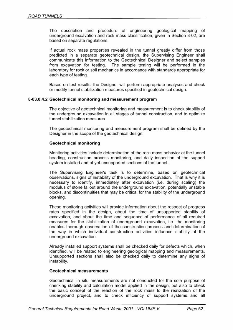
ROAD TUNNELS
The description and procedure of engineering geological mapping of underground excavation and rock mass classification, given in Section 8-02, are based on separate regulations.
If actual rock mass properties revealed in the tunnel greatly differ from those predicted in a separate geotechnical design, the Supervising Engineer shall communicate this information to the Geotechnical Designer and select samples from excavation for testing. The sample testing will be performed in the laboratory for rock or soil mechanics in accordance with standards appropriate for each type of testing.
Based on test results, the Designer will perform appropriate analyses and check or modify tunnel stabilization measures specified in geotechnical design.
8-03.0.4.2 Geotechnical monitoring and measurement program
The objective of geotechnical monitoring and measurement is to check stability of the underground excavation in all stages of tunnel construction, and to optimize tunnel stabilization measures.
The geotechnical monitoring and measurement program shall be defined by the Designer in the scope of the geotechnical design.
Geotechnical monitoring
Monitoring activities include determination of the rock mass behavior at the tunnel heading, construction process monitoring, and daily inspection of the support system installed and of yet unsupported sections of the tunnel.
The Supervising Engineer's task is to determine, based on geotechnical observations, signs of instability of the underground excavation. That is why it is necessary to identify, immediately after excavation (i.e. during scaling) the modulus of stone fallout around the underground excavation, potentially unstable blocks, and discontinuities that may be critical for the stability of the underground opening.
These monitoring activities will provide information about the respect of progress rates specified in the design, about the time of unsupported stability of excavation, and about the time and sequence of performance of all required measures for the stabilization of underground excavation, i.e. the monitoring enables thorough observation of the construction process and determination of the way in which individual construction activities influence stability of the underground excavation.
Already installed support systems shall be checked daily for defects which, when identified, will be related to engineering geological mapping and measurements. Unsupported sections shall also be checked daily to determine any signs of instability.
Geotechnical measurements
Geotechnical in situ measurements are not conducted for the sole purpose of checking stability and calculation model applied in the design, but also to check the basic concept of the reaction of the rock mass to the realization of the underground project, and to check efficiency of support systems and all
General Technical Requirements for Road Works 2001 - VOLUME V Page 52

ROAD TUNNELS
measures taken to stabilize the excavation. These measurements constitute an integral part of the design.
Measurements conducted on tunneling projects can generally be divided into three groups:
• control measurements, conducted to monitor deformations in the underground excavation in order to increase safety of workers and the structure,
• support work measurements, aimed at monitoring rock mass displacements around the underground excavation, as well as stress and strain values in support work elements, in order to optimize excavation and stabilization activities in the underground opening,
• stabilization measurements to monitor stress and strain in secondary concrete lining in order to prove compliance of tunnel with stability requirements.
Control measurements
Control measurements are based on optical three-dimensional measurements of deformation values in the underground excavation.
The control measurement profile is generally formed of five measurement points positioned at the periphery of the underground excavation (cf. Figure 8-03-0.4-1). The measurement point is formed of the measurement point support which is anchored in the shotcrete or the rock mass and on which a bi-reflector or prismatic target is placed. The measurement is conducted by means of an electronic theodolite with an integrated coaxial distance measuring system. The required accuracy of the distance measuring instrument is ≥ ± 1 mm. Measurements are usually performed in the scope of an integrated tunnel monitoring system which also includes settlement measurements and verification of position of tunnel cross sections.
RIs s
Fig
Mespeto mo
General Techn
REPEBench mark
ure 8-03.0.4-1 Control measurement profile
asurement results are immediately processed on personcial program packages for data interpretation, after which
the Supervising Engineer and, if necessary, to the Geotecdem connection.
ical Requirements for Road Works 2001 - VOLUME V
RIREPEBench mark
al computer using they are submitted hnical Designer via
Page 53
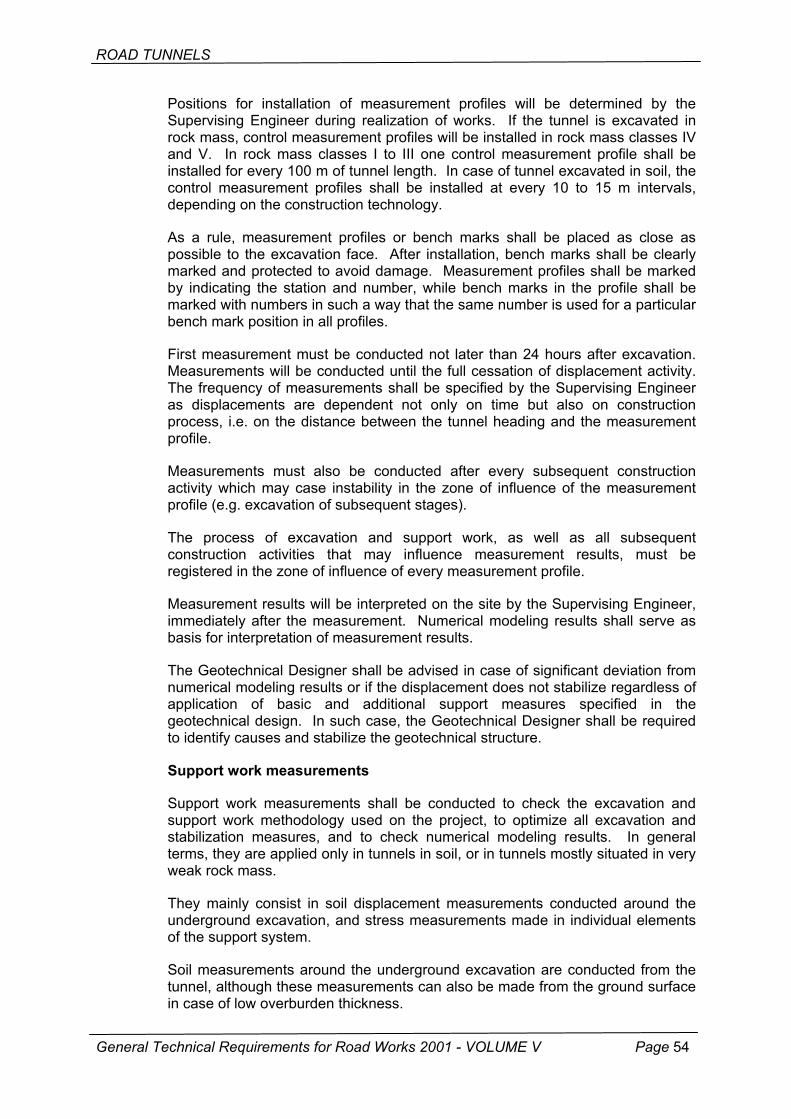
ROAD TUNNELS
Positions for installation of measurement profiles will be determined by the Supervising Engineer during realization of works. If the tunnel is excavated in rock mass, control measurement profiles will be installed in rock mass classes IV and V. In rock mass classes I to III one control measurement profile shall be installed for every 100 m of tunnel length. In case of tunnel excavated in soil, the control measurement profiles shall be installed at every 10 to 15 m intervals, depending on the construction technology.
As a rule, measurement profiles or bench marks shall be placed as close as possible to the excavation face. After installation, bench marks shall be clearly marked and protected to avoid damage. Measurement profiles shall be marked by indicating the station and number, while bench marks in the profile shall be marked with numbers in such a way that the same number is used for a particular bench mark position in all profiles.
First measurement must be conducted not later than 24 hours after excavation. Measurements will be conducted until the full cessation of displacement activity. The frequency of measurements shall be specified by the Supervising Engineer as displacements are dependent not only on time but also on construction process, i.e. on the distance between the tunnel heading and the measurement profile.
Measurements must also be conducted after every subsequent construction activity which may case instability in the zone of influence of the measurement profile (e.g. excavation of subsequent stages).
The process of excavation and support work, as well as all subsequent construction activities that may influence measurement results, must be registered in the zone of influence of every measurement profile.
Measurement results will be interpreted on the site by the Supervising Engineer, immediately after the measurement. Numerical modeling results shall serve as basis for interpretation of measurement results.
The Geotechnical Designer shall be advised in case of significant deviation from numerical modeling results or if the displacement does not stabilize regardless of application of basic and additional support measures specified in the geotechnical design. In such case, the Geotechnical Designer shall be required to identify causes and stabilize the geotechnical structure.
Support work measurements
Support work measurements shall be conducted to check the excavation and support work methodology used on the project, to optimize all excavation and stabilization measures, and to check numerical modeling results. In general terms, they are applied only in tunnels in soil, or in tunnels mostly situated in very weak rock mass.
They mainly consist in soil displacement measurements conducted around the underground excavation, and stress measurements made in individual elements of the support system.
Soil measurements around the underground excavation are conducted from the tunnel, although these measurements can also be made from the ground surface in case of low overburden thickness.
General Technical Requirements for Road Works 2001 - VOLUME V Page 54

ROAD TUNNELS
When the displacement is measured from the tunnel, five boreholes radial to underground excavation are normally drilled. The borehole length is determined based on numerical model which provides an anticipated distribution of displacements around the underground excavation. Measurement tubes are installed in such boreholes and then sealed by contact grouting, and the displacement is measured in the direction of the borehole by means of sliding deformeter. In every borehole, measurement points are spaced at 1 m intervals. Typical support measurement profile for measuring displacement around the underground excavation from the tunnel is presented in Figure 8-03.0.4-2.
Control measurements and topographic survey of displacement at the borehole entrance are also conducted in the profile. The profile is positioned as close as possible to the tunnel heading, and measurements are normally performed continuously, i.e. in 12 hour intervals, depending on construction activities in the zone of the measurement profile, until the full cessation of displacement
Figure 8-03.0.4-2 Typical profile for measuring displacement around under-ground excavation (measurement conducted from tunnel)
A
s
Figure 8-03.0.4-3 Typical support measureand vertical displacemen
General Technical Requirements for Road Works 2001
MJERNE CIJEVIMeasurement tube
NA TERENPOVRSIGround surface
ment profile for measuring horizontal ts from the ground surface
- VOLUME V Page 55
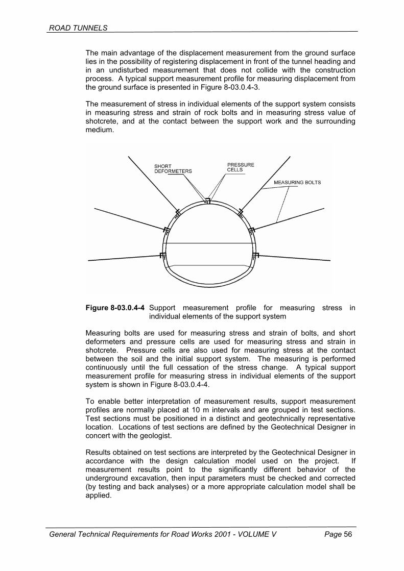
ROAD TUNNELS
The main advantage of the displacement measurement from the ground surface lies in the possibility of registering displacement in front of the tunnel heading and in an undisturbed measurement that does not collide with the construction process. A typical support measurement profile for measuring displacement from the ground surface is presented in Figure 8-03.0.4-3.
The measurement of stress in individual elements of the support system consists in measuring stress and strain of rock bolts and in measuring stress value of shotcrete, and at the contact between the support work and the surrounding medium.
Figure 8-03.0.4-4 Support measurement profile for measuring stress in individual elements of the support system
Measuring bolts are used for measuring stress and strain of bolts, and short deformeters and pressure cells are used for measuring stress and strain in shotcrete. Pressure cells are also used for measuring stress at the contact between the soil and the initial support system. The measuring is performed continuously until the full cessation of the stress change. A typical support measurement profile for measuring stress in individual elements of the support system is shown in Figure 8-03.0.4-4.
To enable better interpretation of measurement results, support measurement profiles are normally placed at 10 m intervals and are grouped in test sections. Test sections must be positioned in a distinct and geotechnically representative location. Locations of test sections are defined by the Geotechnical Designer in concert with the geologist.
Results obtained on test sections are interpreted by the Geotechnical Designer in accordance with the design calculation model used on the project. If measurement results point to the significantly different behavior of the underground excavation, then input parameters must be checked and corrected (by testing and back analyses) or a more appropriate calculation model shall be applied.
General Technical Requirements for Road Works 2001 - VOLUME V Page 56
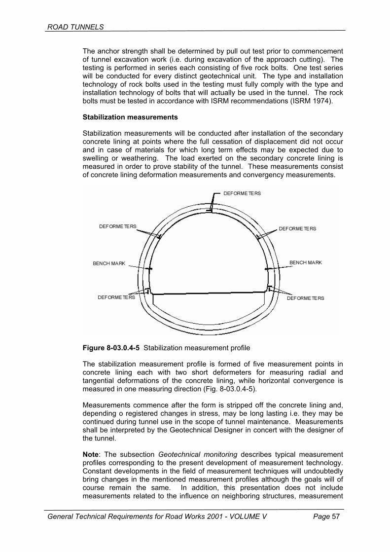
ROAD TUNNELS
The anchor strength shall be determined by pull out test prior to commencement of tunnel excavation work (i.e. during excavation of the approach cutting). The testing is performed in series each consisting of five rock bolts. One test series will be conducted for every distinct geotechnical unit. The type and installation technology of rock bolts used in the testing must fully comply with the type and installation technology of bolts that will actually be used in the tunnel. The rock bolts must be tested in accordance with ISRM recommendations (ISRM 1974).
Stabilization measurements
Stabilization measurements will be conducted after installation of the secondary concrete lining at points where the full cessation of displacement did not occur and in case of materials for which long term effects may be expected due to swelling or weathering. The load exerted on the secondary concrete lining is measured in order to prove stability of the tunnel. These measurements consist of concrete lining deformation measurements and convergency measurements.
Figure 8-03.0.4-5 Stabilization measurement profile
The stabilization measurement profile is formed of five measurement points in concrete lining each with two short deformeters for measuring radial and tangential deformations of the concrete lining, while horizontal convergence is measured in one measuring direction (Fig. 8-03.0.4-5).
Measurements commence after the form is stripped off the concrete lining and, depending o registered changes in stress, may be long lasting i.e. they may be continued during tunnel use in the scope of tunnel maintenance. Measurements shall be interpreted by the Geotechnical Designer in concert with the designer of the tunnel.
Note: The subsection Geotechnical monitoring describes typical measurement profiles corresponding to the present development of measurement technology. Constant developments in the field of measurement techniques will undoubtedly bring changes in the mentioned measurement profiles although the goals will of course remain the same. In addition, this presentation does not include measurements related to the influence on neighboring structures, measurement
General Technical Requirements for Road Works 2001 - VOLUME V Page 57
ROAD TUNNELS
of the condition of material in front of the tunnel heading, measurements related to the problem of water in soil, etc, i.e. special measurements that may be included, if required, in the measurement program.
8-03.0.4.3 Procedure for geotechnical monitoring of tunneling work
The objective of the procedure is to gain complete control over behavior of the underground structure in every phase of realization, and also in final verification of stability of the structure. This enables safe and economical tunnel construction.
Tunnel construction must commence in accordance with solutions given in the geotechnical design.
The procedure is composed of the following steps:
• engineering geological mapping of the excavated part of the tunnel shall be made after every advance; this mapping shall be made by the Contractor's geologist and is subject to periodical checking,
• the engineering geological mapping is the basis for rock mass classification which will be made in accordance with the geomechanical classification. The classification must be made only in case significant change is registered in geological and geotechnical characteristics of the rock mass along the tunnel route, rather than after every advance. The classification is performed by the Supervising Engineer or his assistant - geotechnical engineer specialized in the field of underground structures.
• based on classification results, the Supervising Engineer shall determine the type of the support system and all other measures relating to the excavation and stabilization of excavation work, according to solutions presented in the design,
• the Supervising Engineer shall, based on geotechnical observations, check or modify design recommendations relating to the length of the advance, estimated time of stability of unsupported sections, and the time and sequence of implementation of all measures required for the stabilization of the underground excavation,
• based on results obtained by geotechnical measurements (control measurements) and observations, the Supervising Engineer shall determine whether the underground excavation has become stable, and whether its behavior is in accordance with requirements specified in the design,
• if the behavior of the underground excavation significantly deviates from criteria given in the design, the Supervising Engineer shall communicate this fact to the Geotechnical Designer. Based on excavation material testing, results obtained by geotechnical measurements (control and support work measurements) and back analyses, the designer shall correct input parameters or shall apply a more adequate calculation model and shall, based on such results, modify all measures needed for the stabilization of the underground excavation,
• when the calculation model is in harmony with the behavior of the underground opening, it is possible to optimize the support system on some longer sections presenting uniform geotechnical characteristics of the rock mass. The optimization is performed by gradually reducing the support system at the beginning of the section but always in keeping with criteria for checking stability of the underground excavation.
General Technical Requirements for Road Works 2001 - VOLUME V Page 58

ROAD TUNNELS
Results of all these procedures and analyses constitute an integral part of the design documentation for the tunnel, and they are of highest value in case any problem occurs with respect to stability or maintenance of the structure in the future.
8-03.0.5 Topographic survey of the profile
The Contractor must proceed to a careful and systematic checking of the final profile of the initial tunnel lining in order to make adjustments as needed to obtain the design thickness of the final concrete lining.
The profile may be checked either continuously, using profile scaffold equipped with a template, or at least at every 2.0 m along the station, using modern measurement techniques.
Every deviation from the theoretical profile representing the total thickness of the final concrete lining shall be rectified either by adding shotcrete or by increasing thickness of the internal layer of concrete. In cases when the profile is excessive or when a portion of the profile of the initial lining must be rectified because it projects into the minimum profile specified in the design, the Contractor will be required to perform this work without additional payment.
No rectification of the initial profile of the lining shall be made without prior approval of the Supervising Engineer.
The Contractor must ensure that the minimum profile of the final lining complies with drawings given in the design. In order to determine deviations from the theoretical profile, the Contractor will use a mobile profile scaffold equipped with the template system along its periphery, which shows the minimum profile that is needed to obtain nominal thickness of the final (secondary) concrete lining. The profile scaffold will be placed in such a way that it moves along rails that are used for moving the tunnel lining. Topographic survey methods will be used to check horizontal and vertical alignment of rails, before proceeding to the profile checking. Access should be provided for marking portions of the initial lining protruding into the zone of minimum profile. The profile scaffold can also be realized as a working platform for the initial lining profile rectification, if this becomes necessary, and also for other work on the surfaces of the initial support, as specified in these General Technical Requirements.
The Contractor shall submit to the Supervising Engineer for approval all details about realization of the profile scaffold, together with the corresponding template. After approval, the Supervising Engineer will issue instructions for the systematic topographic checking of template geometry in the course of the profiling.
The Contractor may propose the use of more advanced measurement and data processing techniques for the final profile determination.
The final profile checking will be conducted only after geotechnical measurements have shown that the value of radial displacement in any direction on the tunnel periphery amounts to less than 4 mm per month.
After completion of the support work and after surface treatment as described in these General Technical Requirements, and also after relaxation of deformations (convergence) as indicated in section Geotechnical measurements, the final
General Technical Requirements for Road Works 2001 - VOLUME V Page 59
ROAD TUNNELS
profile for the realization of the secondary concrete lining will correspond to the minimum thickness specified in design drawings.
The Contractor will submit to the Supervising Engineer his proposal for the above mentioned works, and will keep appropriate technical records for every stage of the work.
After profile rectification and final surface treatment activities, the final verification of the profile will be conducted in the presence of and as approved by the Supervising Engineer, and the results of such verification, conducted in longitudinal intervals, will be registered in the site diary.
No support elements such as shotcrete, rock bolt heads, steel arches, etc. will be permitted to protrude beyond theoretical lines of the final concrete lining.
No portion of the rock shall be allowed to protrude, in the area of invert and foundation beams, into area delimited by theoretical lines of excavation.
No reduction in the theoretical thickness of concrete shall be allowed for the concrete invert which is made of shocrete. Excessive excavation must be compensated with structural concrete or shotcrete for invert, as specified in the design.
Lay-bys, recesses and similar facilities shall be realized within an accuracy of plus or minus 5.0 cm with respect to their position specified in the design. Variations in size of such facilities are restricted to - 5.0 cm.
8-03.1 TUNNEL SUPPORT WORK
The tunnel support that is placed immediately after excavation is directly linked to the rock mass class. Standard types of support work for expected rock mass classes are given in the design.
However, due to variations with respect to expected rock mass properties, standard types of support for expected rock mass classes have to be adjusted as necessary during realization of the work. These adjustments shall be made in consultation with the Designer and the Supervising Engineer.
The Contractor shall install support elements in such sequence and in such a way to avoid any fallout and collapse of rock in front of and around the tunnel excavation. The Contractor will protect the tunnel face in accordance with the design and these General Technical Requirements, and in consultation with the Designer and the Supervising Engineer.
8-03.1.1 Shotcrete
All shotcrete works shall be realized in accordance with requirements given in Volume IV (Section 7-01.4.5) of these General Technical Requirements and in keeping with European Specifications for Shotcrete, as issued by the European Federation of Producers of Specialist Products for Structures EFNARC ISBN 0 9522483 1 X, 1996, unless otherwise specified in this Section.
General Technical Requirements for Road Works 2001 - VOLUME V Page 60

ROAD TUNNELS
Shotcrete application
The following preparatory activities for the rock support must be performed prior to shotcrete application:
• weak and loose rock will be removed from the surface, • rock will be mapped to define the total support requirement, and • water seepage zones will be dried either by drainage channels or plugged by
rapid-action cement mix - mortar, or by grouting.
The following will be performed for shotcreting:
• preliminary wetting, unless specified otherwise, • big holes will carefully be filled prior to final application, • shotcreting will start at the bottom and will continue towards to top to avoid
spraying concrete onto the rebound, • nozzle shall generally be kept perpendicular to the surface, • shotcreting speed and distance must be optimized to achieve maximum
adhesion and compaction.
An optimum distance between the nozzle and shotcreted surface ranges from 1.0 to 1.3 meters. The nozzle must be placed perpendicular to the shotcreted surface. At least two nozzles are normally used.
A single layer of shotcrete must not exceed 15 cm in thickness. If greater thickness is required, the next layer will be placed after the previous layer has achieved the strength that is sufficient to withstand an additional layer (or layers). Such additional layers must be placed within three days.
Steel arches, steel fabric and other reinforcing steel shall be covered with shotcrete as indicated in the design. The steel fabric and reinforcing bars must be covered with at least 2 cm of shotcrete from internal side, or as specified in the design. If more than one row of reinforcement is placed, the second row will be placed after the first one is covered with shotcrete.
In the sound rock, the shotcrete layer follows the rock surface with an appropriate curvature. If the sound rock protrudes, the shotcrete thickness cal locally be reduced to two thirds of the specified thickness. This is applied only in good classes of the rock mass.
Any residual shotcrete shall be removed immediately after completion of each shotcreting operation. The reuse of residual material is expressly forbidden. The work must be carried out continuously so that no residual material is generated.
The Contractor shall determine, subject to the approval of the Supervising Engineer, the method for determining the total thickness of shotcrete. The shotcrete thickness determination may be conducted by visual markers/guides placed prior to shotcreting, or by holes drilled after completion of shotcreting.
The shotcrete layer shall be used as surface bedding and initial layer for waterproofing, in accordance with these General Technical Requirements.
General Technical Requirements for Road Works 2001 - VOLUME V Page 61
ROAD TUNNELS
Dry process
The cement and aggregate shall be proportioned in accordance with appropriate specifications and calculations. The proportioning will be conducted by weight. At the time of mixing the aggregate must by dry or sufficiently rinsed and its moisture content must not exceed 7 percent.
The cement and aggregate shall be mixed mechanically in an appropriate mixer. The shotcrete will not be placed if the process can not be completed within 90 minutes after completion of the mixing. The time interval will be even shorter in case of high air temperatures and if the moisture content is high. The minimum mixing time is 3 minutes.
Delivery notes showing the date and time of mixing, the number of the mix, quantity, place of delivery, time of delivery, and the time of completion of placing, shall be submitted to the Supervising Engineer for approval.
In the dry process, powder or liquid additives for the acceleration of setting time are added to the dry mix. Powder additives are proportioned and added immediately before the mix enters the shotcrete placing device.
The liquid accelerator is supplied from a separate pump and is added to the dry mix at the nozzle or near the nozzle.
In cold weather, bonding properties of shotcrete must be preserved by heating the water, aggregate or both, depending on the temperature. Appropriate standards specified in Section 7 of these General Technical Requirements shall be applied.
In hot weather, the water content in aggregates used in dry process shall be maintained above 4 percent.
Wet process
Only liquid setting-time accelerators shall be used in the wet process. These substances are added at the nozzle or near the nozzle. The quantity of setting-time accelerator must be controlled by the supply pump so that it is compliant with the capacity of the concrete pump. The work and material must comply with provisions given in Volume IV (Section 7) of these General Technical Requirements. The nozzle must be of such design that a homogeneous mixing of the accelerator and the wet mixture is ensured.
Cure of shotcrete
The shotcrete shall be cured in accordance with requirements given in Volume IV (Section 7) of these General Technical Requirements or using any other method that has been proven capable of ensuring continuous hydration of cement throughout the curing period.
Curing substances that weaken the bond will not be used in cases when an additional shotcrete layer is to be applied. On site tests shall be conducted before commencement of works to establish relations between layer in cases when a new curing substance is to be used.
General Technical Requirements for Road Works 2001 - VOLUME V Page 62
ROAD TUNNELS
When necessary, the curing substance shall be removed by water jet, by sanding or by a similar procedure, prior to application of the following layer. The shotcrete must be protected against frost until it has attained the compressive strength of no less than 5 MPa.
Quality control
The quality of materials and works shall be controlled in accordance with requirements given in Volume IV (Section 7) of these General Technical Requirements.
8-03.1.2 Reinforcing steel
All materials delivered to the construction site must be compliant with these General Technical Requirements.
8-03.1.2.1 Steel fabric
The type of steel fabric and the type of steel must be compliant with requirements contained in the final design or working design. The following types are recommended: steel sections according to HRN U.M1.091, type 500/560 according to HRN C.B6.013, or types B500A or B500B according to prEN 10080-5.
The steel fabric shall be supplied, stored and tied in accordance with provisions contained in Volume IV (Section 7) of these General Technical Requirements.
The steel fabric shall be installed in such a way to follow as close as practicable irregularities of the excavation or the line of previous shotcrete layers. It will be placed in such a way to avoid its displacement or vibration during shotcreting. The steel fabric shall be placed in greatest possible lengths.
The overlap for steel fabric used in shotcrete lining shall be at least twice as big as the distance between wires in the transverse direction, and equal to the distance between wires in the longitudinal direction. The steel fabric shall be installed in such a way that it can be covered with shotcrete of at least 3 cm in thickness.
The installation of steel fabric is subject to the approval of the Supervising Engineer.
8-03.1.2.2 Reinforcing bars
In the tunnel support work, reinforcing bars are used as an additional reinforcement in area that is subject to extensive stress, depending on local soil conditions. Deformed reinforcing bars, either made of steel type Č0551 according to HRN C.K6.020, or class B according to prEN 10080-1, are used.
Reinforcing bars shall be supplied, stored and tied in accordance with provisions contained in Volume IV (Section 7) of these General Technical Requirements.
Reinforcing bars must properly be tied to the steel fabric which is in turn fixed to the previously placed shotcrete. Overlaps must be presented on appropriate drawings that have been approved by the Supervising Engineer. Reinforcing
General Technical Requirements for Road Works 2001 - VOLUME V Page 63
ROAD TUNNELS
bars shall be placed in such a way that they can be covered with shotcrete of at least 3 cm in thickness.
8-03.1.2.3 Steel fiber reinforcement
Steel fiber reinforcement must be compliant with the standard ASTM A 820:1996 Standard Specification for Steel Fibers for Fiber-Reinforced Concrete.
8-03.1.2.4 Steel arches
This section concerns delivery and installation of steel arches that are used as initial support in underground excavations. Steel arches are fabricated in such a way to comply with geometrical requirements for excavation in every category of rock mass, including all applicable tolerances.
Fabrication of steel arches
The steel to be used in the fabrication of steel arches shall be obtained from manufacturers that are known to provide good quality steel, and that are duly certified for such production. The Contractor is required to supply copies of evidence furnished by the Manufacturer showing the type of steel and test results related to such steel.
Hot rolled sections for arches
The following hot rolled sections are used:
• medium flanged and wide flanged I-sections, • PE and HE series according to DIN 1025-2, -3, -4 and -5, • bell-shaped TH sections according to HRN B.M2.104, • sections based on other standards, if specified in the design.
The minimum yield strength of steel sections is 240 N/mm2, all in accordance with HRN C.B0.500 or EN 10025.
Arch girders must be dimensioned in accordance with requirements given in the design.
Steel sections may be welded only if a specified technological procedure is used, and this procedure must be compliant with appropriate Croatian standards. The technological procedure for welding is subject to the approval of the Supervising Engineer.
Holes for ties, bracing, and all bolted connections may be realized by mechanical means. Flame drilling is not allowed.
Bars, face plates, ties for arches
Bars, face plates, and ties are made of steel having minimum yield strength of 240 N/mm2, in accordance with Croatian or European standards. The dimensions must be compliant with the design. Threaded tie bars and braces must be of appropriate length so that free ends of thread beyond the nut are at least 25 mm in symmetry lines of arches.
General Technical Requirements for Road Works 2001 - VOLUME V Page 64
ROAD TUNNELS
Lattice girders for arches
Lattice girders are made of wieldable reinforcing steel haven the minimum yield strength of 500 N/mm2 according to prEN 10080-1, steel sheets and L-section have the minimum yields strength of 240 N/mm2 according to HRN C.B0.500 or EN 10025. The Contractor must submit to the Supervising Engineer for approval an appropriate evidence about the bearing capacity of lattice girders.
Lattice girders must be welded in accordance with the standard HRN C.T3.095 or DIN 488-7 and DIN 4099.
The strength class of bolts used for connecting lattice girders must be at least 8.8 according to HRN M.B1.023 or DIN 267-2.
Installation
Steel arches shall be installed in accordance with drawings contained in the design. Steel arches shall be brought to their final position by means of timber blocks and wedges. Arches will be linked to one another on site using fastening rods. Steel arches will be covered with shotcrete and the protective layer must be at least 20 cm in thickness. Steel arches shall be placed perpendicular to the tunnel axis. Arch joints must be such that requirements for the static bearing capacity of arches are complied with.
TH sections must be installed in such a way that their convex side faces the edge of the excavation.
Documentation
Documentation must be submitted to the Supervising Engineer in accordance with these General Technical Requirements. In addition, the following must be submitted prior to the start of the works:
• all detail drawings relating to the fabrication of steel arches, • details of joints, arch connection, arch spacers, geometry, etc., • erection procedures and layout plan, • evidence that the material complies with steel grade requirements, • evidence of the bearing capacity of lattice girders.
8-03.1.2.5 Piles
Piles are support elements that are installed before commencement of excavation works. They are used when the condition of rock and soil is such that extensive overbreak, cave in or fallout of rock, may reasonably be expected.
Pile driving may be local or systematic, depending on the impact the rock/soil conditions have on safety of work and overbreak prevention.
Material
Seamed steel pipes with the nominal external diameter of 42.4 mm and 48.3 mm shall be used as piles. The minimum wall thickness of such steel pipes shall be 3 mm. The length of steel pipes shall exceed by at least one meter the length of the planned excavation cycle. The steel of such pipes must comply with
General Technical Requirements for Road Works 2001 - VOLUME V Page 65
ROAD TUNNELS
requirements specified in HRN C.B5.025 or EN 10217-1. The mortar used for grouting shall be compliant with these General Technical Requirements.
Deformed reinforcing steel rods can be used instead of steel pipes. The minimum diameter of such rods shall be 25 mm.
Installation
Piles shall be installed as shown in drawings contained in the design, or as directed by the Supervising Engineer. The spacing between pipes or rods around the crown must be compliant with distances indicated in the drawings, but shall in any case be adjusted to dominant topographic features at the tunnel heading.
Steel pipes or rods shall be placed into previously drilled holes at 30 to 40 cm intervals.
Pipes will be covered with mortar, either before or after pipe installation, as specified by the Contractor in consultation with the Supervising Engineer.
8-03.1.2.6 Steel lagging
The steel lagging is mostly used in soil lacking in cohesion and characterized by poor bearing capacity, in order to prevent cave in of material during excavation and immediately following the excavation. The use of steel lagging is always accompanied with the assembly of steel arches.
Material
The steel lagging is made of steel grade Č0371 compliant with the standard HRN C.B0.500 or S235JR, and with the EN 10025. The thickness must range between 4 and 6 mm. Other dimensions and shape of the lagging shall be selected in accordance with the excavation length and in keeping with the support requirements in the zone behind the heading.
Installation
The lagging shall be driven at intervals shown in the drawings. The lagging shall be driven prior to excavation i.e. prior to advance, at the distance of no less than 0.8 m from the heading.
Voids and holes behind the lagging shall be filled with shotcrete or by contact grouting with cement mortar.
8-03.1.2.7 Rock bolts
Provisions contained in this section refer to all rock bolts placed either locally or systematically into the arch, side walls or invert. Rock bolts are a part of the initial support, and their objective is to activate a composite action of the surrounding rock and shotcrete, in order to increase the load bearing capacity of the initial tunnel support. Rock bolts periodically needed for the support of excavation face during tunnel driving activities are also covered by these provisions.
General Technical Requirements for Road Works 2001 - VOLUME V Page 66
ROAD TUNNELS
Rock bolts shall be placed in accordance with lengths and distributions presented in drawings for every standard support system and for individual rock mass classes, unless otherwise jointly defined by the Contractor, the Designer and the Supervising Engineer.
Rock bolt types
The following rock bolt types are used in tunnel support:
• SN rock bolts • PG rock bolts • IBO rock bolts • Swellex rock bolts
SN rock bolts and PG rock bolts
SN and PG rock bolts are made of deformed reinforcing bars (rebars). The steel grade must be Č0551 according to HRN C.K6.020 or type B500B according to prEN 10080-1. One end of the bolt has a metrical thread for the corresponding face place and nut of class 5 or 8 according to HRN M.B1.028.
The Contractor must submit to the Supervising Engineer for approval an evidence of an appropriate bearing capacity of the entire assembly (threaded bolt + nut + face plate) and of the couplings used for the extension of rock bolts.
Grouted rock bolts with external thread (IBO bolts)
The IBO bolt body is made of the externally threaded steel pipe with a drill bit on one end, and a nut with face plate on the other. IBO bolts can be extended using couplings with internal thread.
IBO bolts must be supplied with the manufacturer's declaration of breaking force for the full bolt assembly (body + nut + face plate), such as 250 kN. The load bearing capacity of the coupling must correspond to that of the rock bolt assembly. These rock bolts are normally made of steel grade according to HRN C.B0.500 (EN 10025) or seamless pipes according to HRN C.B5.021 (prEn 10216-1).
The Contractor must supply to the Supervising Engineer for approval an evidence of an appropriate bearing capacity of the entire assembly (threaded bolt + nut + face plate) and of the couplings used for the extension of rock bolts.
Swellex bolts
The load bearing capacity of super Swellex bolts, which are used for systematic anchoring, shall be no less than 200 kN.
"Standard" Swellex bolts, with the load bearing capacity of 110 kN, may be used for local bolting and rock bolting during excavation of the tunnel.
Face plates shall be of such quality that they provide good contact and safe transfer of anchoring force onto the shotcrete, steel arch or rock surface.
General Technical Requirements for Road Works 2001 - VOLUME V Page 67
ROAD TUNNELS
Installation
SN bolts
The face plate must be shaped in such a way to enable an uniform contact even if the bolt is not fully perpendicular to the surface and, in combination with the nut, it must enable safe transfer of anchoring force onto the anchor plate.
For all rock bolt types, boreholes shall be drilled to the depth required for the bolt length to be used in the support work for an appropriate rock mass class, and the borehole diameter shall be such to enable the best possible injection of the grout, and also the best possible connection and assembly. The minimum borehole diameter shall exceed by 10 mm that of the rock bolt.
The borehole shall be cleaned from any drilling waste, sludge and other residual substances. The rock bolt installation must commence within 3 hours following the drilling and borehole preparation.
Before the rock bolt is installed, the entire borehole shall be filled with cement mortar in such a way that the grouting pipe is placed to the full depth of the borehole and is gradually pulled out as the grouting progresses. The nozzle will remain immersed in the grout while the pipe is pulled out so that the air can go out as the borehole is filled. After that, the rock bolt is placed into the borehole.
The nut of the grouted rock bolt shall be tightened not later than after two advance sequences or 12 hours after installation. Nuts shall be tightened using a properly calibrated torque wrench. The tightening torque shall be defined in keeping with the nut thread diameter and, in this respect, a tensile force of 20 kN will be applied.
Bolt jointing may be permitted if the work space is restricted and/or if the rock bolts are very long. In such cases the number of joints shall be restricted to an absolute minimum. The load bearing capacity of rock bolts extended in such manner shall not be less than that of the rock bolt consisting of a single element only.
PG bolts
All provisions given in the preceding paragraphs can also be applied for PG bolts, the only exception being that the grouting can in this case be performed after installation of the rock bolt. Here the borehole is grouted with a special device which enables closing of the borehole while the grouting is in progress. The air is expelled from the borehole via a pipe attached along the whole length of the bolt. Then the grout is pumped until the borehole is completely filled. The borehole is considered full when the grout is coming out at the end of the pipe.
IBO bolts
IBO bolts are used in ground conditions where no other rock bolts can efficiently be installed. IBO bolts are installed by drilling into soil without extraction of the drill bit. The grouting compound, the grouting pressure, and the quantity of grout shall be determined by the Contractor depending on soil conditions and in accordance with instructions given by the rock bolt manufacturer. The installation procedure shall be subject to the approval of the Supervising Engineer.
General Technical Requirements for Road Works 2001 - VOLUME V Page 68

ROAD TUNNELS
Swellex bolts
Boreholes for these bolts shall be realized down to the specified depth. Boreholes shall be cleaned from any drilling waste, sludge and other residual substances. The rock bolt installation must commence within 2 hours following the borehole drilling.
Bolts shall be placed and expanded in accordance with recommendations given by the manufacturer. Equipment recommended by the bolt manufacturer shall be used for rock bolt expansion.
Rock bolts shall be drained after expansion.
Bolt testing
Mortar for grouting
Before acceptance tests for rock bolts, tests will be made with available cement and sand in order to determine the mix capable of meeting requirements relating to strength and workability using available equipment. The workability may be improved with appropriate additives. The influence of additives on the increase in strength shall be checked by testing as described in this section. The grouting mortar shall be tested using cubes measuring 5x5x5 cm. The cubes shall be cured in water. Five cubes shall be prepared for every compressive strength testing. The resulting strength is an average value obtained from three values that remain after elimination of the highest and lowest values. During realization of this work, the cube-shaped sample shall be taken every week from the grout hose, at the nozzle, for all five anchoring procedures. The above procedure must be used in preparation and evaluation activities.
The grouting mortar must have the following compressive strength:
after 24 hours = 8 N/mm2 after 28 days = 20 N/mm2, w/c ratio = 0.25 - 0.30 - pure cement w/c ratio = 0.50 - 0.60 - cement/sand (0-5 mm) mix
Rock bolt pullout test
The pull out test shall be conducted in accordance with ISRM Doc 2, Part 1 Recommended method for rock bolt testing.
a) Acceptability testing
A detailed testing program, compliant with the above ISRM document, shall be submitted to the Supervising Engineer for approval before the testing.
Any deviation from the recommended ISRM method shall be subject to the approval of the Supervising Engineer.
Test report shall be prepared immediately after completion of the testing and shall be promptly submitted to the Supervising Engineer for approval.
General Technical Requirements for Road Works 2001 - VOLUME V Page 69
ROAD TUNNELS
The following information shall be provided for each type of rock bolt:
• type of bolt, testing equipment used, point of load application during testing, deformation registered during the testing, and analysis of test results as specified in the ISRM document,
• explanation and actions to be taken if the pull-out test is unsuccessful.
The acceptability testing shall be conducted for all bolt types specified in the design. This testing will be performed prior to the commencement of underground excavation activities.
The testing shall be performed in geological conditions that are similar to those that are likely to be encountered during tunneling work. The bolt testing position shall be selected by the Supervising Engineer.
At least five bolts shall be tested for each bolt type. Depending on the testing procedure and results, the Supervising Engineer may require that additional tests be performed.
Appropriate testing equipment, as specified in the above mentioned ISRM document, must be obtained to enable proper testing of elongation, bolt displacement and tensioning force.
Maximum load shall amount to 250 KN although an another value may also be used subject to prior approval.
b) Testing during tunnel excavation
The Supervising Engineer shall select rock bolts to be used in bolt testing. Five bolts shall be selected for every type from the first 100 bolts to be placed in the tunnel. Five out of every subsequent 200 bolts will be selected for testing. The force used in bolt testing shall amount to at least 80 percent of the declared load bearing capacity of the bolt.
Bolts proven unacceptable during this testing, or bolts that can be pulled out, shall be replaced. For every unsatisfactory result, the Supervising Engineer shall require testing of additional bolts situated in the vicinity of the unsatisfactory bolt. All other requirements are similar to those given for the previous testing.
Rock bolt installation record
The Contractor shall keep record of rock bolt installation for every advance sequence and this record shall be subject to the approval of the Supervising Engineer. The record must contain the following information: composition of the grouting mix, drilling depth, rock bolt length and type, deviation from theoretical position, grouting method and time, fastening time, additional remarks, etc.
This record must be complemented with documents containing bolt testing results.
8-03.1.2.8 Pipe roof
The pipe roof is composed of steel pipes that are installed in the tunnel vault. They are used for materials with no initial stability at the level of the underground
General Technical Requirements for Road Works 2001 - VOLUME V Page 70
ROAD TUNNELS
opening (soil and very weak rock mass) in order to enable excavation of the top portion of the tunnel, thus avoiding further division of opening in this zone.
Material
Perforated seamless steel pipes 114.3 mm (4") in outside diameter, and at least 5 mm in wall thickness. The steel grade must be Č1213 according to HRN C.B5.021 or SPT410 according to prEN 10216-1.
Installation
The pipe roof shall be installed as shown in the drawings contained in the design, or as directed by the Supervising Engineer.
Steel pipes shall be installed simultaneously with the drilling, in such a way that the central or eccentric bit pulls the pipe into the borehole during the drilling process.
Steel pipes shall be placed from the excavation face toward the unexcavated soil. In unstable boreholes, the steel pipes can be used as formwork for drilling. The spacing between steep pipes in the crown of the excavation must be compliant with the corresponding distances indicated in the drawings, as adjusted to actual geological conditions encountered at the excavation face.
After the drilling, steel pips will be cleaned with compressed air prior to grouting. The grouting will be conducted at low pressure.
8-03.1.2.9 Micropiles
Micropiles shall be placed in the support for the top tunnel section in areas with shallow overburden and under houses. Micropiles transfer load from shotcrete lining onto the surrounding rock mass thus reducing settlement of shotcrete lining in the top section and the risk of shearing between tunnel lining in top section and the lining of the temporary invert, while also increasing safety of side walls during bench excavation.
Material
The micropile is formed of a seamless steel pipe up to 60 mm in diameter with an round outside thread, and with no less than 6 mm in wall thickness. The steel pipe is fully grouted with mortar. The diameter of the borehole for pile shall correspond to the outside pile diameter.
The type of steel for these pipes shall be specified in the design, based on the standard HRN C.B5.021 or prEN 10216-1. IBO bolts can also be used as micropiles.
Installation
Steel pipes shall be placed into the previously drilled holes or, alternatively, self-drilling bolts will be used (such as IBO bolts). Corrugated steel or PVC pipes with no less than 120 mm in internal diameter shall be placed into the shotcrete lining to facilitate the drilling.
General Technical Requirements for Road Works 2001 - VOLUME V Page 71
ROAD TUNNELS
Prior to installation, appropriate tests must be conducted to prove whether steel piles have been fully covered with mortar. The number of test piles and the testing procedure shall be proposed by the Contractor, and is subject to the approval of the Supervising Engineer.
8-03.2 GROUTING WORK
The grouting work in tunnel must be conducted in accordance with the design or report tailored to individual projects, and will be subject to the approval of the Supervising Engineer.
Prior to the start of grouting, the Contractor has to determine, in consultation with the Supervising Engineer, all details for the realization of these works, namely:
• grout composition, • grouting pressures, • borehole arrangement, direction and depth, • time sequence of grouting activities, • type and capacity of equipment.
The Contractor must perform grouting works using services of highly skilled personnel experienced in these works, and the work must be performed using modern equipment.
The grouting pressure shall be selected in such a way to avoid damage to concrete lining or, in relation to overburden thickness, harmful loosening of the rock material and loss of grout.
Only those grouting devices that are capable of reaching specified pressure shall be used in grouting operations.
Grouting devices must be equipped with calibration mechanism for recording pressures and quantity of grout used.
The Contractor must keep an appropriate record of drilling and grouting works and this record must contain all information needed for the inspection and calculation of works (description of works and equipment, spatial arrangement of boreholes, time sequence of grouting activities, quantity of grout used per borehole, description of significant events, etc.).
Tunnel grouting works include:
a) contact grouting of empty space remaining after installation of steel lagging or formwork, and filling of all other voids between the rock mass and the concrete lining so as to obtain full contact between the rock and concrete.
b) consolidation grouting for stabilization of the rock mass around the excavated opening and for the improvement of its mechanical properties.
Contact grouting
The contact grouting of empty space between the rock and lining is performed only in the top heading of the concrete lining, where the possibility of poor contact between the rock mass and concrete is the greatest. The existence of empty
General Technical Requirements for Road Works 2001 - VOLUME V Page 72

ROAD TUNNELS
space must be confirmed by test drilling prior to the start of contact grouting in the top heading of the tunnel.
All cost related to the contact grouting in the top heading of the concrete lining shall be borne by the Contractor who is required to include such work in his price for the concrete lining, as these activities are an integral part of the internal concrete lining the cost of which is recognized to the Contractor in full.
Contact grouting works relating to the filling of empty space behind the external primary load bearing lining (lagging, steel rings, driven formwork, etc.) shall be recognized and calculated in accordance with prices given in cost estimate presented in the Contractor's bid. These works must also be carried out immediately after realization of the external load bearing lining, in order to prevent any loosening of the rock mass around opening due to empty space behind the lining.
The calculation will be made according to the drilling length and consumption of grout (measured by weight), which will be recorded on a daily basis in the progress record.
The Contractor shall not be entitled to any compensation for the grouting work caused by inadequate rock excavation or poor concreting of internal concrete lining (such as grouting of internal concrete lining made necessary due to poor quality of concrete, grouting for improving mechanical quality of rock rendered excessively loose due to inadequate blasting or excavation).
In such cases, the Contractor is required to perform repair grouting activities, at his own expense, whenever instructed to do so by the Supervising Engineer.
In tunnel sections where the waterproofing of the primary lining was conducted by shotcrete, the grouting work must be carried out in such a way that no damage is caused to the waterproofing by grouting holes drilled through the secondary concrete lining.
The grouting mix is basically made of the cement suspension or cement mortar. The testing and inspection of cement mix will be carried out in accordance with provisions applied for concrete testing.
Consolidation grouting
Tunnel points and zones to be subjected to consolidation grouting shall be specified by the supervising authority. The distribution of boreholes, their depth, borehole orientation, grouting mix composition and grouting pressure, shall be defined in the design or report made following realization of the test section.
The composition of the consolidation grouting mix shall be defined in the grouting report based on geotechnical properties of the rock mass. Consolidation grouting mixes can be: cement suspensions, cement mortars, or mixes based on clay suspension, with or without additives, in combination with cement. Grouting mixes must be tested and subjected to inspection during grouting activities.
Grouting must be performed in such a way to obtain, whenever practicable, similar pressures along the perimeter of the outside lining.
General Technical Requirements for Road Works 2001 - VOLUME V Page 73
ROAD TUNNELS
Upon completion of this work, the consolidation grouting will be checked by drilling test holes with pressure probe, in order to determine actual watertightness of the grouted rock.
The Contractor will not be compensated for consolidation grouting of the rock which was in fact loosened by the Contractor's failure to act in accordance with regulations relating to excavation and protection activities (inadequate blasting, insufficient support work, etc.
The Contractor must include in the unit price for drilling and grouting all costs relating to the erection, relocation and dismantling of all required devices and scaffolds, proper closing with cement mortar of all grouting holes along the entire length, cleaning concrete lining from borehole-generated cement suspension, cleaning waste material and grouting mass in the tunnel, and all disturbances and interruptions caused by parallel works, as such activities shall neither be recognized to the Contractor nor considered for payment.
The calculation will be made according to pay items for all works realized per meter of drilling and kilogram for grout used, based on properly kept record, which is duly signed by the Supervising Engineer on the daily basis.
8-03.3 CALCULATION OF WORK AND PAYMENT
Shotcrete
The shotcrete lining placed in tunnels, parking places, cross cuts and lay-bys shall be calculated for every nominal thickness per square meter along the P line (as shown in figures 8-02-6, 8-02-7 and 8-02-8). The length is measured along the axis.
Any additional shotcrete needed for filling voids between individual pipes of the pipe roof shall not be measured for payment, as it is covered by an appropriate unit rate. Any additional shotcrete needed to widen cross section below the pipe roof shall not be measured for payment. It is included in an appropriate unit rate.
Reinforcement
The steel fabric placed in tunnels, parking places, cross cuts and lay-bys shall be calculated by weight along the P line as shown in figures 8-02-6, 8-02-7 and 8-02-8). The length is measured along the axis. Overlaps, waste material, additional and accessory material for fastening shall not be calculated separately.
Any additional reinforcement needed to widen cross section below the pipe roof shall not be measured for payment. It is included in an appropriate unit rate.
The reinforcement that is used for tunnel support shall be calculated by weight.
Steel arches
Steel arches for rock support shall be calculated per meter along the P line (as shown in figures 8-02-6, 8-02-7 and 8-02-8). Accessory material, steel sheets at connections, bolts, etc. shall not be calculated for payment, as they are covered by the unit rate.
General Technical Requirements for Road Works 2001 - VOLUME V Page 74
ROAD TUNNELS
Piles
Pipes or rods shall be calculated per unit for various lengths. The drilling and grouting shall not be paid for separately.
Steel lagging
The steel lagging shall be calculated by weight.
Rock bolts
Rock bolts shall be calculated per unit for various types and lengths. The drilling, grouting and expansion (Swellex) shall not be paid for separately. Accessory materials such as anchor plates, face plates, nuts and connections, shall not be calculated for payment, as they are covered by the unit rate.
Grouting works
The grouting work shall be calculated and paid for according to pay items per meter of drilling and per quantity of grout consumed, based on properly kept diary signed by the Supervising Engineer on the daily basis.
Unit rates for various pay items include all work, equipment and material needed for the realization and completion of works, including testing and quality control. Support elements needed to protect the excavation face shall not be paid for separately, as they are covered by unit rates for such support elements.
8-03.4 STANDARDS AND TECHNICAL REGULATIONS
ENV 1991 Bases for design and actions on structures. ENV 1992 Design of concrete structures. ENV 1997 Geotechnical design. EN 12336 Tunneling machines, machines with shields, pushing machines,
lining equipment, safety requirements. EN 815 Safety criteria for unshielded tunnel boring machines and rock
drilling machines. EN 12110 Tunneling machines, air locks, safety requirements. EN 12111 Tunneling machines, road headers, continuous miners and
impact rippers, safety requirements. EN 60204 Electrical installations. EN ISO/12236 Geotextiles and geotextile-related products - Static puncture test. EN ISO/16727 Plastic bituminized cloth and waterproofing layer; testing. EN ISO/16776 Plastic materials for molds, polyethylene materials for molds
(PE); preparation of components and determination of their properties.
EN ISO/53363 Plastic foil testing; tear test on trapezoidal samples with longitudinal slot.
EN ISO/53370 Plastic foil testing; determination of thickness by mechanical measurement.
EN ISO/53377 Thin plastic layer testing; determination of dimensional stability. EN ISO/53387 Artificial aging and aging of plastics and elastomers by exposure
to xenon arc radiation. General Technical Requirements for Road Works 2001 - VOLUME V Page 75
ROAD TUNNELS
EN ISO/53455 Plastics testing; strength testing. EN ISO/53457 Plastics testing; determination of elastic modulus by testing
strength, compression and bending. EN ISO/53479 Testing plastics and elastomers; determination of density. EN ISO/53488 Plastic foil testing, hole test. EN ISO/53515 Determination of the tear strength of rubber elastomers and thin
layers of plastics using Graves angle test piece with nick. EN ISO/53521 Determining behavior of rubber and elastomer when exposed to
the action of fluids and vapors. EN ISO/53532 Elastomer testing; determination of elastomeric plate resistance
to the action of fluids. EN ISO/53739 Plastics testing; influence of fungi and bacteria, visual inspection,
change in mass and physical properties. EN ISO/53861 Textile testing; reduction test and break test; definition of terms. ASTM 820 Standard requirements for reinforced-concrete steel fibers. ASTM A569 Steel plate for sliding disks. ASTM DI693 Chemical resistance. DIN 4062 Plastic materials for bonding obtained by cold process for
drainage pipes, bonding materials for prefabricated parts of concrete, requirements, testing and treatment.
General Technical Requirements for Road Works 2001 - VOLUME V Page 76
ROAD TUNNELS
8-04 DRAINAGE
This section contains technical requirements for the realization of:
• ground water intercepting facilities, • longitudinal drainage facilities behind the internal concrete lining with
inspection lay-bys, • main drainage facilities with appropriate manholes, • cross connections for pipes, • curbs for controlled evacuation of liquids from pavement surface, • hollow curbs for the reception - evacuation of liquids from the pavement, • siphon for the inspection and cleaning, as well as for the evacuation of liquids
from pavement, and discharge of such liquids into the main drainage system.
If ground water not revealed during preliminary investigations is encountered during construction at the level below that of the longitudinal drainage, this problem will be solved by introducing an appropriate drainage system based on a separate design.
During realization of these works, builders should bear in mind that fact that by irregular interruption of water inflow, i.e. by preventing evacuation and causing backwater flow, a hydrostatic pressure can build up and act on the outside lining, and the water will negatively affect bearing capacity of the rock mass in formations susceptible to change of physical-mechanical properties in contact with water.
8-04.0.1 Documentation
Before realization of any drainage activities, the Contractor shall submit to the Supervising Engineer an evidence attesting to the acceptability of planned materials, and their compliance with quality requirements specified in the design and in these General Technical Requirements.
8-04.1 INTAKE STRUCTURES
8-0.4.1.1 Evacuation of smaller water streams encountered at excavation face
Description of work
The work relating to the evacuation of water from the excavation face comprises interception of water by appropriate drainage elements from the surface of excavated face, and evacuation of such water by pipes or semi-pipes and its discharge into the longitudinal drainage system behind the internal concrete lining.
The size of interception elements, pipes and semi-pipes and their quantity must be compliant with the requirements given in the design, and shall be subject to the approval of the Supervising Engineer.
Interception elements, pipes and semi-pipes shall be attached along the periphery of the tunnel profile, and then lined with quick-setting mortar.
General Technical Requirements for Road Works 2001 - VOLUME V Page 77
ROAD TUNNELS
Interception elements or pipes shall be realized in such a way to enable measurement of the water inflow before the entry of water into the drainage system. The quantity of water flowing out of the drainage system must also be measured, and an appropriate record must be made.
Material
Corrosion resistant lightweight plastic material such as polypropylene (PP) and polyethylene (PE) should be used for the construction of water intercepting elements.
Drainage pipes and semi-pipes must also be made of these materials (prEN 13476-1), as their flexibility enables adjustment to curved surfaces and facilitates pipe connection.
Calculation of work
Water interception activities at excavation faces are calculated by unit of water interception structure, including supply of materials, fabrication and assembly of intercepting elements, supply of pipes or semi-pipes and assembly, material for fastening intercepting elements and pipes, quick-setting cement mortar lining, and all required scaffolding.
Any additional work caused by failure to act in accordance with the design and these General Technical Requirements, shall not be approved for payment as additional or extra work.
8-04.1.2 Evacuation of bigger water streams encountered at excavation face
Description of work
In case of extensive inrush of water, it is often necessary to build a drainage system that will be used to intercept water along the entire cross section, and to carry it to the space behind the concrete lining.
Drainage boreholes will be drilled in specified cross sections, perpendicular or diagonal to the tunnel axis, based on the distance of the link to be concreted. The depth, profile and orientation of boreholes shall be defined on the spot.
These boreholes are linked with pipes or semi-pipes using quick-setting mortar and the water is evacuated to the longitudinal drainage system behind the lining. A manhole must be provided to enable access to and inspection of such points.
Material
Plastic (HDPE) and rigid PVC pipes, complying with the standard prEN 13476-1 and these General Technical Requirements, shall be used for realization of these drainage systems.
Calculation of work
Water interception work at excavation face shall be calculated per meter of fully realized interception, including drilling of drainage boreholes, supply of pipes or semi-pipes, installation, pipe fastening material, as well as the lining made of quick-setting cement mortar.
General Technical Requirements for Road Works 2001 - VOLUME V Page 78
ROAD TUNNELS
Any additional work caused by failure to act in accordance with the design and these General Technical Requirements, shall not be approved for payment as additional or extra work.
8-04.1.3 Evacuation by realization of drainage boreholes
Description of work
Drainage boreholes shall be realized using generally accepted acknowledged drilling techniques. If the borehole passes through the material where the borehole wall stability can not be achieved, then protective pipes (casing tubes) shall be used in drilling operations.
Screen (perforated) pipes shall be installed after realization of boreholes in materials with unstable walls. These pipes may be made either of plastic (HDPE or hard PVC) or steel, with strip-shaped or circular openings. The use of screen pipes with strip-shaped openings is recommended. The width of strips or circular holes will depend on the granularity of material in which the borehole is realized.
The clear opening of screen pipes is specified in the design but is also subject to the approval of the Supervising Engineer.
Perforated casing tubes that will be left in the borehole where they will act as filters may also be used.
The diameter of the borehole with casing tubes or without such tubes will depend on the diameter of screen pipes. After completion, the borehole must be in such condition that ensure safe installation of screen pipes.
The borehole entrance must be made of a full pipe and it must be descended down to the depth of at least 1.0 meter from the housing by which the pipe is stabilized at the exit from the borehole.
The quantity of outflowing water will be measured after installation but before connection with the drainage system, and an appropriate protocol will be made and submitted to the Supervising Engineer for examination. If the water carries with it an unacceptable quantity of the fine grained material, the drainage borehole will be cleaned by water or air until no more than 2 percent (by volume) of fine grained material remains in a liter of outflowing water.
When drainage boreholes are drilled in compact rock material a "torpedoing" by explosive may be performed at the bottom to enable better collection of water (linking of discontinuities in low-permeability layers) and in these cases perforated tubes may be used as casing. Such drainage boreholes are linked together by a common drainage pipe which is the shortest route to carry water to the horizontal drainage system behind the internal lining. The location, number, depth, orientation and size of these boreholes shall either be determined in a separate design, or approved on site by the Supervising Engineer.
Material
Plastic (HDPE) and rigid PVC pipes, complying with the standard prEN 13476-1 and these General Technical Requirements, shall be used for realization of these drainage systems.
General Technical Requirements for Road Works 2001 - VOLUME V Page 79

ROAD TUNNELS
Calculation of work
Water interception work at excavation face shall be calculated per meter of fully realized interception, including drilling of drainage boreholes, supply of pipes or semi-pipes, installation, pipe fastening material, as well as the lining made of quick-setting cement mortar.
Any additional work caused by failure to act in accordance with the design and these General Technical Requirements, shall not be approved for payment as additional or extra work.
8-04.2 DRAINAGE
Longitudinal drainage will be realized in tunnel sections drilled through the water impermeable soil, where hydrostatic pressure may be expected. The longitudinal drainage is made of perforated pipes of specified diameter in a filtration layer. The filtration layer must be linked to the rock in the excavation along the entire pipe length, so as to enable transfer of water into the drainage pipe.
Drainage pipes shall be placed in accordance with the strike and dip indicated in the design, and shall be laid onto the concrete bedding.
Longitudinal drainage pipes that are used for the evacuation of ground water will be covered and protected with filtration layer. The filtration layer is made of drainage concrete or filtering gravel or sand, and must be compliant with the filtering rule applicable to the material in which the drainage is performed, i.e. it must comply with requirements given in the design and in the standard HRN U.S4.062.
When drainage of the subbase is required, it will be performed in accordance with the design and based on the DIN 4262-1 and DIN 4095.
Inspection lay-bys will be placed into the final concrete lining to enable permanent maintenance of the longitudinal drainage. The dimensions and spacing of such lay-bys will be as indicated in the design.
Material
Perforated drainage pipes must comply with standards indicated in these General Technical Requirements. The pipes will be made of HDPE or hard PVC (prEN 13476-1), and their nominal diameter will be no less than DN 150.
The filtration layer will be made of gravel or sand, and the grain size must be compliant with filtration requirements as indicated in the standard HRN U.S4.062. The drainage concrete will be made of the ordinary Portland cement and natural aggregate of the same grain size. The aggregate to cement ratio will be 8:1 by volume or 10:1 by weight. The quantity of water will not be greater than that needed to cover all parts of the aggregate, without creating an excess weight. The porous drainage concrete will be compacted by hand only.
Calculation of work
All work related to longitudinal drainage shall be calculated per meter of fully completed drainage, including supply of perforated pipes and fittings, concrete bedding, and filtration fill or drainage concrete.
General Technical Requirements for Road Works 2001 - VOLUME V Page 80
ROAD TUNNELS
Any additional work caused by failure to act in accordance with the design and these General Technical Requirements, shall not be approved for payment as additional or extra work.
8-04.3 PRINCIPAL DRAINAGE SYSTEM
The principal drainage system is formed of the main drainage pipeline by which water captured by drainage system, and liquids from the pavement (oily water), are carried to the separator situated outside of the tunnel tube. The main drainage pipeline has manholes that are spaced at regular intervals, i.e. at side-drainage or pavement drainage connection points.
8-04.3.1 Drainage pipe
Description of work
Drainage pipes are placed on the concrete bedding into the previously excavated trench, and a protective concrete lining is placed above the pipes. The thickness of the bedding and protective lining shall be at least 1/4 of the pipe diameter, or as indicated in the design and these General Technical Requirements.
The method and technology for the excavation of drainage trenches is subject to the approval of the Supervising Engineer. The Contractor must submit evidence that the method and technology for the excavation of drainage trenches will not have a harmful effect on the work already realized.
Pipes will be placed in accordance with the lines and grades shown in the design. Grade line errors with respect to positioning of drainage pipes must be within an accuracy of plus or minus 1.0 cm.
The main drainage pipe will be placed after completion of excavation and following the tunnel bottom cleaning, so that it is not polluted with sludge. This requirement may be neglected in justified cases, subject to the approval of the Supervising Engineer.
The main drainage pipeline must be watertight. The watertightness of the main drainage pipeline shall be checked in accordance with the standard EN 1610.
Works relating to the realization of the main drainage pipe must be compliant with requirements given in the design, EN 1610 and in these General Technical Requirements.
Material
The main drainage pipeline is made of:
• flexible pipes: deformed HDPE pipes linked together by welding or couplings, with rubber baskets (prEN 13476-1), hard PVC pipes connected by spigot-and-socket joints, with rubber gaskets (ONORM B5/184; DIN 19534; HRN U.G1 500), polyester pipes connected with patent couplings (DIN 16689-1 and 2; DIN 19565-1 and 5).
• rigid pipes: concrete pipes with integrated rubber gaskets, measuring 2.5 m in length (DIN 4034), asbestos cement pipes with patent couplings, with two rubber gaskets (HRN B.C4.061; HRN B.C4.061/1), and cast-iron pipes with spigot-and-socket joints, and with rubber gaskets (EN 598).
General Technical Requirements for Road Works 2001 - VOLUME V Page 81

ROAD TUNNELS
Calculation of work
The work for the realization of the main drainage pipeline shall be calculated per meter of main drainage pipe realized, and shall also include trench excavation, supply of pipes and couplings, pipe laying, concrete bedding, protective concrete lining, backfilling and transport of excess material to the disposal site up to 1.5 km away from the tunnel portal. The price includes watertightness testing in accordance with the standard EN 1610.
Any additional work caused by failure to act in accordance with the design and these General Technical Requirements, shall not be approved for payment as additional or extra work.
8-04.3.2 Manholes
Description of work
Manholes shall be realized as monolithic concrete structures or as precast elements (typical elements). They shall be watertight and spaced as specified in the design.
Typical prefabricated manholes shall be selected in keeping with the pipe material selected (HDPE, PVC, concrete, asbestos cement, polyester).
Entrances must be covered with cast iron covers with the load bearing capacity of 40 Mp, and with clear opening of 664 m (HRN M.16.227).
Material
Monolithic concrete manholes shall be made of concrete (C25/30) and shall be reinforced in accordance with the structural analysis given in the design. Manhole design and materials must be compliant with these General Technical Requirements.
The same applies to prefabricated concrete manholes, while prefabricated manholes made of other materials (HDPE, PVC, concrete, asbestos cement, polyester) shall be compliant with specific standards relating to these materials, as indicated in these General Technical Requirements.
Calculation of work
Manhole construction works shall be calculated per unit of a fully realized manhole, and shall include trench widening, supply of materials, concrete fabrication and placing, all required formwork, steel reinforcement, cunette fabrication, manhole cover and step irons, backfilling and the transport of excess material from the excavation to the place of disposal no more than 1.5 km away from the tunnel portal.
The transport must also be provided if prefabricated manholes are used. The price includes watertightness testing in accordance with EN 1610.
Any additional work caused by failure to act in accordance with the design and these General Technical Requirements, shall not be approved for payment as additional or extra work.
General Technical Requirements for Road Works 2001 - VOLUME V Page 82
ROAD TUNNELS
8-04.3.3 Transverse pipe connections
Description of work
Transverse pipe connections to the main drainage pipeline are links between the longitudinal drainage and the main drainage pipeline. A manhole is realized at the point of connection on the main pipeline. Pipes are placed in the excavated ditch on the concrete bedding, and are lined with concrete the thickness of which shall be at least 1/4 of the pipe profile, unless otherwise specified in the design.
Material
Works related to the construction of transverse links between the longitudinal drainage and the main drainage pipeline shall be calculated per meter of such connection, and shall include trench excavation, pipe supply, placing of the concrete bedding, realization of the protective concrete lining, backfilling and the transport of excess material from the excavation to the place of disposal no more than 1.5 km away from the tunnel portal. The price includes watertightness testing in accordance with EN 1610.
Any additional work caused by failure to act in accordance with the design and these General Technical Requirements, shall not be approved for payment as additional or extra work.
8-04.4 HOLLOW CURBS
Description of work
Prefabricated hollow curbs shall be placed onto a leveling cement mortar layer 20-30 mm in thickness, in accordance with the lines and grades as specified in the design. Connections between individual elements shall be sealed with the permanently elastic putty or an another sealant if approved by the Supervising Engineer.
Before starting the work, the Contractor is required to submit to the Supervising Engineer the documentation confirming that prefabricated elements are compliant with quality requirements specified in the design, particularly with respect to their load bearing capacity, drainage capability, and other features as specified in the design and in these General Technical Requirements.
Hollow curbs shall be fabricated in casting yards that must be compliant with appropriate standards as well as with requirements contained in these General Technical Requirements.
Material
Hollow curbs shall be realized in accordance with provisions contained in Volume IV (Section 7) of these General Technical Requirements, and must meet topographic survey requirements with respect to their positioning.
Calculation of works
Works related to the realization of prefabricated hollow curbs shall be calculated per meter of fully competed curb, and shall include supply, placing and realization of connections.
General Technical Requirements for Road Works 2001 - VOLUME V Page 83

ROAD TUNNELS
The price includes watertightness testing in accordance with EN 1610.
Any additional work caused by failure to act in accordance with the design and these General Technical Requirements, shall not be approved for payment as additional or extra work.
8-04.5 CURBS
Description of work
The works shall be realized and calculated according to provisions contained in Volume II (Section 3-04.7) of these General Technical Requirements.
8-04.6 MAINTENANCE SHAFTS AND SIPHONS
Description of work
Siphon shafts for the interruption of air contact between pavement drainage and the main drainage line and for the inspection, cleaning and connection of pavement drainage to the main drainage line, are made of prefabricated concrete elements that are placed at regulator intervals in connection with hollow water-evacuation curbs. Siphon shafts must be watertight, and the corresponding inspection will be carried out in accordance with EN 1610.
Material
Concrete works for siphon shafts shall be carried out in accordance with provisions contained in Volume IV (Section 7) of these General Technical Requirements. Appropriate topographic survey requirements must be met during realization of these shafts. Siphon shafts must be watertight, and the corresponding inspection will be carried out in accordance with EN 1610.
Calculation of work
Works relating to the construction of siphon shafts shall be calculated per unit of fully realized siphon shape, and shall include all required excavation work, supply of concrete elements, all required formwork, steel reinforcement, transport of excess material from the excavation to the place of disposal no more than 1.5 km away from the tunnel portal. The price includes watertightness testing in accordance with EN 1610. Any additional work caused by failure to act in accordance with the design and these General Technical Requirements, shall not be approved for payment as additional or extra work.
8-04.7 STANDARDS AND TECHNICAL REQUIREMENTS
EN 1610 1997 Construction and testing of drains and sewers. DIN 4262-1 Sicker- und Mehrzweckrohre aus PVC-U und PE-HD
für Verkehrswege- und Tiefbau; Anforderungen und Prüfung.
DIN 4095 Baugrund; Dranung zum Schutz baulicher Anlagen; Planung, Bemessung und Ausfuhrung.
General Technical Requirements for Road Works 2001 - VOLUME V Page 84
prEN 13476-1 Thermoplastics piping systems for non-pressure underground drainage and sewerage - Structured-wall
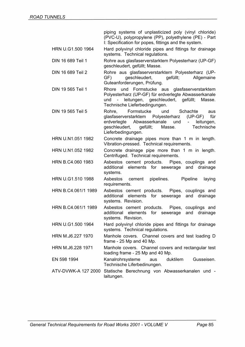
ROAD TUNNELS
piping systems of unplasticized poly (vinyl chloride) (PVC-U), polypropylene (PP), polyethylene (PE) - Part I: Specification for popes, fittings and the system.
HRN U.G1.500 1964 Hard polyvinyl chloride pipes and fittings for drainage systems. Technical regulations.
DIN 16 689 Teil 1 Rohre aus glasfaserverstarktem Polyesterharz (UP-GF) geschleudert, gefüllt; Masse.
DIN 16 689 Teil 2 Rohre aus glasfaserverstarktern Polyesterharz (UP-GF) geschleudert, gefüllt; Allgemaine Guteanforderungen, Prüfung.
DIN 19 565 Teil 1 Rhore und Formstucke aus glasfaserverstarktem Polyesterharz (UP-GF) für erdverlegte Abwasserkanale und - leitungen, geschleudert, gefüllt; Masse. Technische Lieferbedingungen.
DIN 19 565 Teil 5 Rohre, Formstucke und Schachte aus glasfaserverstarktem Polyesterharz (UP-GF) für erdverlegte Abwasserkanale und - leitungen, geschleudert, gefüllt; Masse. Technische Lieferbedingungen.
HRN U.N1.051 1982 Concrete drainage pipes more than 1 m in length. Vibration-pressed. Technical requirements.
HRN U.N1.052 1982 Concrete drainage pipe more than 1 m in length. Centrifuged. Technical requirements.
HRN B.C4.060 1983 Asbestos cement products. Pipes, couplings and additional elements for sewerage and drainage systems.
HRN U.G1.510 1988 Asbestos cement pipelines. Pipeline laying requirements.
HRN B.C4.061/1 1989 Asbestos cement products. Pipes, couplings and additional elements for sewerage and drainage systems. Revision.
HRN B.C4.061/1 1989 Asbestos cement products. Pipes, couplings and additional elements for sewerage and drainage systems. Revision.
HRN U.G1.500 1964 Hard polyvinyl chloride pipes and fittings for drainage systems. Technical regulations.
HRN M.J6.227 1970 Manhole covers. Channel covers and test loading D frame - 25 Mp and 40 Mp.
HRN M.J6.228 1971 Manhole covers. Channel covers and rectangular test loading frame - 25 Mp and 40 Mp.
EN 598 1994 Kanalrohrsysteme aus duktilem Gusseisen. Technische Liferbedinungen.
ATV-DVWK-A 127 2000 Statische Berechnung von Abwasserkanalen und -laitungen.
General Technical Requirements for Road Works 2001 - VOLUME V Page 85
ROAD TUNNELS
8-05 WATERPROOFING
8-05.0 DESCRIPTION
This part of General Technical Requirements covers tunnel tube waterproofing, by means of thermoplastic PVC foils, before realization of the secondary tunnel lining.
Insulating materials, such as those used for sealing expansion joints, other joints, pipelines and water supply installations, are beyond the scope of these General Technical Requirements.
Tunnel tube waterproofing, based on the use of thermoplastic PVC foils, is formed of:
• base layer, • insulating layer, • protective layer.
As a rule, the insulating layer is realized as a single layer, except in cases when the water pressure exceeds 0.3 MN/m2 (3 bars).
The base layer serves as mechanical protection for the insulating layer and is realized using an appropriate type of geotextile.
The insulating layer serves as a direct protection of the secondary tunnel lining against water action.
The protective layer is installed at the tunnel bottom zone immediately above the drainage channel, and is realized using the material similar to that used for the insulating layer.
At concrete lining joints, the insulating layer is strengthened from the inside by welding a strip made of the same material.
8-05.0.1 Quality requirements for materials
Base layer
The base layer shall be made of nonwoven geotextile based on continuous polypropylene fibers, so that it forms a stable grid of uniform thickness and surface texture.
Surface mass and thickness
The nominal surface mass of geotextile must not be less than 500 g/sq.m., and the measured value may deviate from the nominal one by no more than -10% (HRN EN 965).
Mechanical properties
Mechanical properties of geotextiles used as base layers of waterproofing systems are presented in Table 8-05.0-1.
General Technical Requirements for Road Works 2001 - VOLUME V Page 86

ROAD TUNNELS
Hydraulic properties
The geotextile must have good drainage properties, so that the capacity of water outflow in the plane (transmissivity), at normal pressure of 0.2 MN/m2 and at the hydraulic gradient of i = 1, is higher than 1x10⁻⁶ m2/s (HRN EN ISO 12958).
Table 8-05.0-1 Quality requirements for mechanical properties of geotextile as a function of the base course
Property Requirement Test method
Maximum tensile force; longitudinal, transverse, diagonal, minimum 15 kN/m HRN EN ISO 10319
Maximum tensile yield strength; longitudinal, transverse, diagonal, minimum
70 % HRN EN ISO 10319
Puncture strength, minimum 2,5 kN HRN EN ISO 12236
Chemical properties
The geotextile must be chemically stable in the pH range from 2 to 13.
Flammability
The geotextile must meet at least minimum requirements for the flammability class B2, in accordance with the standard DIN 4102-1 and, when set on fire, it must not generate smoke vapors or toxic gases.
Insulating layer
Thermoplastic synthetic foils, made of softened polyvinyl chloride (PVC-P) shall be used as insulating layer.
Such thermoplastic PVC foils must be watertight, they must present no bubbles, cracks and voids, and they may be either transparent or colored with a "signaling layer".
Thickness
The insulating layer shall be made of thermoplastic PVC foil at least 2 mm in nominal thickness. The thickness of the thermoplastic PVC foil shall be determined in accordance with the standard HRN EN 1849-2.
The thickness of the thermoplastic PVC foil is determined by the mean value and the individual value. The mean thickness of the tested sample can be no more that 5 percent below the nominal thickness. Individual values may be no more than 15 percent below the nominal thickness.
Physicomechanical properties
Physical and mechanical properties of thermoplastic PVC foils are presented in Table 8-05.0-2.
Chemical properties
General Technical Requirements for Road Works 2001 - VOLUME V Page 87
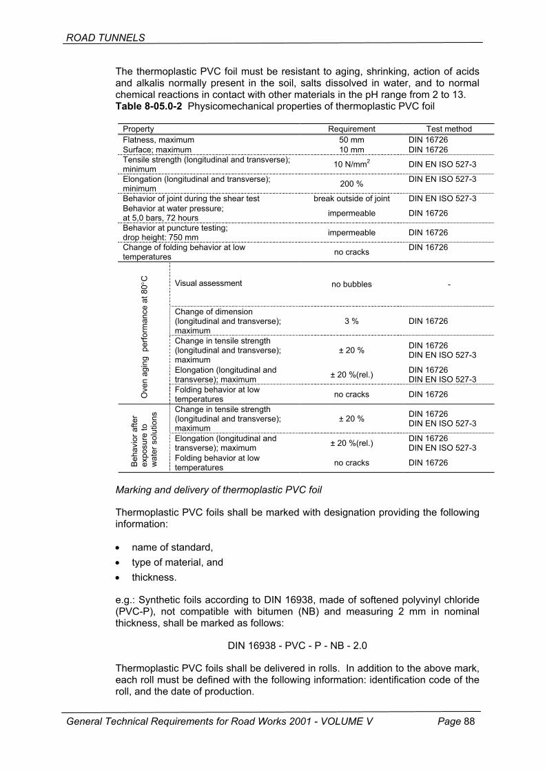
ROAD TUNNELS
The thermoplastic PVC foil must be resistant to aging, shrinking, action of acids and alkalis normally present in the soil, salts dissolved in water, and to normal chemical reactions in contact with other materials in the pH range from 2 to 13. Table 8-05.0-2 Physicomechanical properties of thermoplastic PVC foil
Property Requirement Test method Flatness, maximum 50 mm DIN 16726 Surface; maximum 10 mm DIN 16726 Tensile strength (longitudinal and transverse); minimum 10 N/mm2 DIN EN ISO 527-3
Elongation (longitudinal and transverse); minimum 200 % DIN EN ISO 527-3
Behavior of joint during the shear test break outside of joint DIN EN ISO 527-3 Behavior at water pressure; at 5,0 bars, 72 hours impermeable DIN 16726
Behavior at puncture testing; drop height: 750 mm impermeable DIN 16726
Change of folding behavior at low temperatures no cracks DIN 16726
Visual assessment no bubbles -
Change of dimension (longitudinal and transverse); maximum
3 % DIN 16726
Change in tensile strength (longitudinal and transverse); maximum
± 20 % DIN 16726 DIN EN ISO 527-3
Elongation (longitudinal and transverse); maximum ± 20 %(rel.) DIN 16726
DIN EN ISO 527-3
Ove
n ag
ing
per
form
ance
at 8
0°C
Folding behavior at low temperatures no cracks DIN 16726
Change in tensile strength (longitudinal and transverse); maximum
± 20 % DIN 16726 DIN EN ISO 527-3
Elongation (longitudinal and transverse); maximum ± 20 %(rel.) DIN 16726
DIN EN ISO 527-3
Beh
avio
r afte
r ex
posu
re to
w
ater
sol
utio
ns
Folding behavior at low temperatures no cracks DIN 16726
Marking and delivery of thermoplastic PVC foil
Thermoplastic PVC foils shall be marked with designation providing the following information:
• name of standard, • type of material, and • thickness.
e.g.: Synthetic foils according to DIN 16938, made of softened polyvinyl chloride (PVC-P), not compatible with bitumen (NB) and measuring 2 mm in nominal thickness, shall be marked as follows:
DIN 16938 - PVC - P - NB - 2.0
Thermoplastic PVC foils shall be delivered in rolls. In addition to the above mark, each roll must be defined with the following information: identification code of the roll, and the date of production.
General Technical Requirements for Road Works 2001 - VOLUME V Page 88

ROAD TUNNELS
Furthermore, with each shipment the producer or the supplier must send the document containing the following information:
• commercial name and mark of the product, • name of manufacturer, • number of rolls in the shipment, • total area of foil delivered in the shipment, • date of delivery.
8-05.1 CONSTRUCTION OF WATERPROOFING
The tunnel is to be protected with waterproofing in zones affected with water inrush or in zones of permanent water inflow. In such cases the tunnel shall be protected by lining its walls and crown, from one side drainage to the other. Before proceeding to thermoplastic PVC placing, the protective geotextile layer shall be placed onto the shotcrete bedding.
8-05.1.1 Shotcrete bedding
A shotcrete layer of optimum thickness and strength shall be applied onto the entire profile of the tunnel tube. Shotcrete bedding must be dry prior to the application of the waterproofing layer. The evenness of the shotcrete surface shall be such to enable an undisturbed connection of individual thermoplastic PVC foils. In order to prevent foil damage, no remains of reinforcing steel, anchors, steel arches, wire, etc. shall be left on the shotcrete surface. The evenness of shotcrete surface must be compliant with the following requirements:
• length to height ratio of each irregularity must not be less than 10 : 1, • the smallest radius of each irregularity must not be less than 20 cm.
a
≥ 10 a
Figure 8-05.1-1 Allowable unevenness of shotcrete surface
Figure 8-05.1.-2 Allowable curvature of shotcrete surface
General Technical Requirements for Road Works 2001 - VOLUME V Page 89

ROAD TUNNELS
Any inrush of water (extensive seepage) must be properly controlled, as thermal welding of the thermoplastic PVC foil can not be performed in the presence of water.
8-05.1.2 Geotextile installation - base layer
A protective layer of geotextile shall be placed onto the properly prepared shotcrete bedding. Its function is to prevent damage to thermoplastic foil during realization of concrete lining, and to efficiently carry water to the drainage channel.
Adjacent geotextile strips must overlap by no less than 5 cm (so that the entire surface of shotcrete is covered), and they are attached to shotcrete with synthetic washers, compatible with the thermoplastic PVC foil, through which nails are driven using a special nail driving tool.
Three to five washers must be placed per every square meter (although the number of washers may vary depending on the evenness of the shotcrete surface). Washers ensure adherence of the protective geotextile layer, and later serve to connect the thermoplastic PVC foil to the shotcrete, until completion of the secondary concrete lining.
8-05.1.3 Geotextile installation - insulating layer
The insulating layer made of thermoplastic PVC foil is placed from one side drainage to the other by welding it with hot air onto the previously placed washers.
The thermoplastic PVC foil is placed and attached with washers in such a way that the insulating layer exposure to tensile stress is reduced to minimum during realization of concrete lining.
Adjacent strips of thermoplastic PVC foil must be placed with an optimum overlap so that they are fully watertight after the welding. Prior to welding, overlaps between adjacent foil strips must be cleaned in order to eliminate any dust, grease or water.
Watertight connection of adjacent foil strips is obtained by a thermal welding process, using a special machine which makes two parallel welds along the joint, about 5 cm in total thickness, in a single passage. An unwelded portion ("hose") 1 to 2 cm in width, remaining between these parallel welds, enables welding quality inspection by a non-destructive method.
If the length of the thermoplastic PVC foil is not sufficient for covering the entire perimeter of the tunnel tube (e.g. due to deviations or cave-in during tunnel excavation, and due to tunnel lay-by realization), the foil shall be extended by adding a new piece of foil. In this case, an overlap connection will be made, i.e. adjacent foils will be positioned so that they overlap by at least 5 cm and the entire length of this joint will be made watertight by welding.
The insulating layer of thermoplastic PVC foil must not be installed when the ambient air temperature is below +5° C.
General Technical Requirements for Road Works 2001 - VOLUME V Page 90
ROAD TUNNELS
8-05.1.4 Protection of insulating layer
Before proceeding to secondary lining concreting and before installation of formwork, the surface of the foil must be checked for mechanical damage. Any damage identified during this visual inspection must be repaired prior to concreting by making overlaps and by welding a new piece of foil. The watertightness of insulating layer repaired in this way shall be checked by visually inspecting continuity of the single weld.
As mechanical foil damage may occur during concreting, a direct contact between wedge and foil must be prevented during formwork closing with wooden wedges. In this respect, a protective geotextile or foil layer will be placed at the point of contact. In zones where joints are made in the concrete lining, the insulating layer must be strengthened from inside by wielding strips no less than 50 cm in width.
8-05.2 QUALITY CONTROL
8-05.2.1 Initial testing
Before the start of the waterproofing work, the Contractor is required to obtain from the Manufacturer or Suppler documents attesting to the acceptability of all materials he intends to use in the waterproofing work. The evidence of acceptability is a compliance certificate, which must be no more than 3 years old, and has to be issued for every material by a competent authority.
The Contractor shall submit such material acceptability evidence to the Supervising Engineer for review, at least 20 days before the planned start of the waterproofing work. No more than 10 days after the receipt of the material acceptability evidence the Supervising Engineer shall inform the Contractor about the approval or rejection of the acceptability evidence submitted by the Contractor.
The Supervising Engineer may require the Contractor to make a test section of waterproofing work, before giving approval for a continuous work. The cost of such test section, and the cost of work supervision at such test section, shall be borne by the Contractor.
8-05.2.2 Control testing
The Contractor is required to conduct control tests to evaluate quality of geotextile and thermoplastic PVC foils, and to check quality of welds during connection of thermoplastic PVC strips.
Geotextile
The following testing will be made at every delivery of up to 5000 square meters of geotextile, and at every subsequent 5000 square meters of delivered geotextile:
• thickness HRN EN 964-1 • mass per unit area HRN EN 965 • tensile strength HRN EN ISO 10319 • elongation HRN EN ISO 10319
General Technical Requirements for Road Works 2001 - VOLUME V Page 91

ROAD TUNNELS
Thermoplastic PVC foil
The following testing will be made at every delivery of up to 5000 square meters of thermoplastic PVC foil, and at every subsequent 5000 square meters of thermoplastic PVC foil delivered to the site:
• thickness HRN EN 1949-2 • tensile strength DIN EN ISO 527-3 • elongation HRN EN ISO 527-3
Welds
The connection of thermoplastic PVC strips by welding must be checked at every weld. Records about this inspection shall be submitted by the Contractor to the Supervising Engineer not later than 24 hours after the testing.
All double welds must clearly be marked with numbers.
Double welds shall be checked by introducing air into the space ("hose") between two parallel welds. One end of the "hose" shall be closed with special pliers, and a valve with a pressure gauge shall be placed on the other end. The air under pressure (2.5 bars) is introduced via this valve. If the pressure does not drop below 2.0 bars within ten minutes, the weld is considered acceptable (smaller fall in pressure is due to elasticity of the thermoplastic PVC foil).
Once the quality of welding is checked, the joint shall be overlapped and spot welded to the placed foil by hot air at 50 cm intervals. Weld testing must be properly documented by protocol.
8-05.2.3 Audit testing
During realization of waterproofing, the Client shall check the quality of waterproofing work and the quality of materials used in this work. Audit testing results constitute, together with control testing results, the basis for the determination of quality and for the acceptance of completed work
Geotextile
The following testing will be made at every delivery of up to 15000 square meters of geotextile, and at every subsequent 15000 square meters of geotextile delivered to the site:
• thickness HRN EN 964-1 • mass per unit area HRN EN 965 • maximum tensile strength HRN EN ISO 10319 • elongation HRN EN ISO 10319 • puncture strength HRN EN ISO 12236 • flammability DIN 4102-1 • in-plane flow capacity HRN EN ISO 12958
General Technical Requirements for Road Works 2001 - VOLUME V Page 92

ROAD TUNNELS
Thermoplastic PVC foil
The following testing will be made at every delivery of up to 15000 square meters of thermoplastic PVC foil, and at every subsequent 15000 square meters of thermoplastic PVC foil delivered to the site:
• thickness HRN EN 1849-2 • tensile strength DIN EN ISO 527-3 • elongation DIN EN ISO527-3 • dimension change at 80°C DIN 16726 • flammability DIN 4102-1 • behavior under water pressure DIN 16726 • bending at -20°C DIN 16726
All these tests, except flammability, are related to the sample in its condition at the delivery and after exposure to water solutions.
Welds
The connection of thermoplastic PVC strips by welding must be checked on at least 30 percent of all welds.
8-05.3 CALCULATION OF WORK AND PAYMENT
The base geotextile layer and the insulating layer made of thermoplastic PVC foil shall be calculated per square meter of completed layer, complying with quality requirements specified in the design and these General Technical Requirements as measured along the theoretical line P, cf. Figures 8-02-2 to 8-02-5.
The area of completed layers shall be determined based on the theoretical outside perimeter of concrete lining and the length in the tunnel axis.
Quantities determined in this way shall be paid for in accordance with contract unit prices per square meter.
The price includes all costs related to the supply of material, all cost of equipment, and all other costs incurred for the realization of works and performance of control testing for materials and works.
8-05.4 STANDARDS AND TECHNICAL REGULATIONS
HRN EN 964-1:2001 Geotextiles and geotextile-related products - Determination of thickness at specific pressures - Part 1: Single layers
HRN EN 965:2001 Geotextile and geotextile-related products - Determination of mass per unit area
HRN EN ISO 10319:2001 Geotextiles - Wide-width tensile test HRN EN ISO 12236:2001 Geotextiles and geotextile-related products - Static
puncture test. HRN EN ISO 12958:2001 Geotextiles and geotextile-related products -
Determination of water flow capacity in their plane.
General Technical Requirements for Road Works 2001 - VOLUME V Page 93
ROAD TUNNELS
HRN EN 1849-2:2002 Flexible sheets for waterproofing - Determination of thickness and mass per unit area - Part 2: Plastic and rubber sheets for roof waterproofing
DIN EN ISO 527-3:1995 Plastics - Determination of tensile properties - Part 3: Test conditions for films and sheets
DIN 16726:1986 Plastic roofing felt and waterproofing sheet; testing DIN 4102-1:1998 Fire behavior of building materials and building
components - Part 1: Building materials; concepts, requirements and tests
DIN 16938:1986 Plasticized polyvinyl chloride (PVC-P) waterproofing sheet incompatible with bitumen; requirements
General Technical Requirements for Road Works 2001 - VOLUME V Page 94
ROAD TUNNELS
8-06 CONCRETE WORK
8-06.0 CONCRETE COMPOSITION REQUIREMENTS
When defining concrete for the secondary lining, different and sometimes even contradictory requirements must be complied with. On the one hand, it is considered that a sufficient temperature of concrete must be obtained to enable faster hardening and hence easier formwork stripping, as well as a rapid gain in strength, while on the other hand high temperature is favorable to the formation of cracks. Special requirements may call for high concrete temperature, and thus cause cracking. But if the reaction is delayed, the formwork stripping time is extended.
Proper mix design for concrete used for secondary lining calls for quantitative and qualitative optimization of materials in order to obtain the best possible preconditions for various requirements such as:
• workability, • formwork stripping time and strength during formwork stripping, • minimum cracking, • properties in use.
Properties are checked on hardened concrete in order to obtain an optimum concrete mix design, despite the fact that requirements may sometimes be contradictory. Adding cement containing crushed mineral additions or covering a specific part of binder with hydraulically efficient additions such as fly ash, is recommended as a means to reduce temperature generated stress. In addition, very fine additives may improve workability of fresh concrete and impermeability of concrete ("filler effect"). In addition to high resistance to sulfates, cements with low C3A content also feature slow rise in temperature, while presenting lower incidence of cracking due to temperature stress, which is why they are a preferred choice for "watertight secondary lining".
Given a favorable temperature of fresh concrete, the selected quantity of cement and additives must guarantee full realization of required properties and strength parameters. In addition to mix design, the temperature of fresh concrete also influences the rise in temperature and hardening speed of concrete used as secondary lining, which is of high significance, not only for rapid stripping of formwork, but also for obtaining maximum concrete temperature while avoiding formation of cracks. Fresh concrete temperatures ranging from 13 to 18°C have proven to be particularly favorable. Fresh concrete temperatures of less than 10°C evidently slow down the hardening process, while temperatures in excess of 25°C have a negative effect on crack formation. Fresh concrete temperatures higher than 30°C are not permitted.
Rise in concrete temperature depends on the fresh concrete temperature, creation of heat (heat of hydration generated by cement or binder, cement/binder proportioning), thickness of structural elements, and on external influences (e.g. air temperature, air velocity). If prevention of crack formation is of primary significance, care should be taken to reduce concrete temperature as much as possible.
General Technical Requirements for Road Works 2001 - VOLUME V Page 95
ROAD TUNNELS
8-06.0.1 Workability
Measures normally used for consistency testing do not provide a full insight into the fresh concrete properties, the sum of which is expressed as "workability". A simple spreading test is not sufficient for proper evaluation of pumping capability of concrete mixes.
The consistency of concrete used as pumped concrete for secondary lining must be adjusted to placing conditions.
The spreading rate from 42 to 46 cm (min. 40 cm, max. 48 cm) - F2/F3 consistency (according to EN 206) is normally required for concrete placed in the crown.
Concrete placement efficiency is dependant on the type of aggregate, grain size distribution and grain shape. Very fine mineral admixtures (such as fly ash) greatly contribute to the movability and consistency of mixes.
In addition to durability of hardened concrete, the workability of fresh concrete is also favorably influenced by the use of air-entraining agents which create micropores of air , with a limited introduction of air; a desirable quantity of air normally varies from 2.5 to 3.5 percent, while the maximum deviation from the absolute value ranges from 3 to 4 percent.
8-06.0.2 Formwork stripping time, strength during formwork stripping
To avoid formation of voids, the formwork stripping should be delayed as much as practicable. To maintain a normal 24-hour cycle for one segment concreting, the formwork stripping time may vary from 13 to 14 hours for concrete placed in the crown, which is favorable from the standpoint of concrete technology. If the formwork stripping time needs to be less than 10 hours, then appropriate measures against excessive cooling and drying must be taken.
The strength used in formwork stripping operations must not be excessive, as the concrete temperature is very high at the time when the possibility for crack formation is the greatest. For the concrete placed in tunnel crown, the strength at formwork stripping, as measured in the structure itself, normally varies from 1.5 N/mm2 to 3.0 N/mm2.
8-06.0.3 Crack prevention measures
Crack formation in concrete lining is most often due to stress generated in concrete because of its inability to contract during cooling and as a result of shrinkage.
General Technical Requirements for Road Works 2001 - VOLUME V Page 96
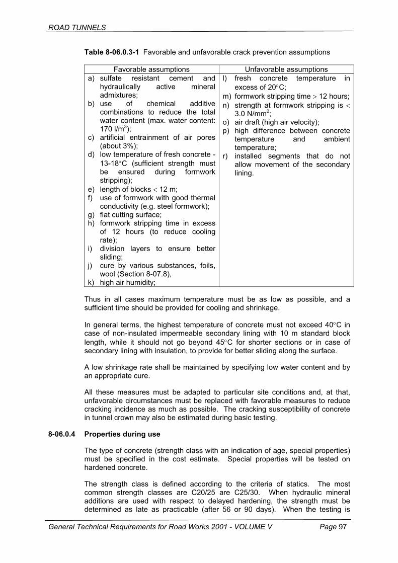
ROAD TUNNELS
Table 8-06.0.3-1 Favorable and unfavorable crack prevention assumptions
Favorable assumptions Unfavorable assumptions a) sulfate resistant cement and
hydraulically active mineral admixtures;
b) use of chemical additive combinations to reduce the total water content (max. water content: 170 l/m3);
c) artificial entrainment of air pores (about 3%);
d) low temperature of fresh concrete - 13-18°C (sufficient strength must be ensured during formwork stripping);
e) length of blocks < 12 m; f) use of formwork with good thermal
conductivity (e.g. steel formwork); g) flat cutting surface; h) formwork stripping time in excess
of 12 hours (to reduce cooling rate);
i) division layers to ensure better sliding;
j) cure by various substances, foils, wool (Section 8-07.8),
k) high air humidity;
l) fresh concrete temperature in excess of 20°C;
m) formwork stripping time > 12 hours; n) strength at formwork stripping is <
3.0 N/mm2; o) air draft (high air velocity); p) high difference between concrete
temperature and ambient temperature;
r) installed segments that do not allow movement of the secondary lining.
Thus in all cases maximum temperature must be as low as possible, and a sufficient time should be provided for cooling and shrinkage.
In general terms, the highest temperature of concrete must not exceed 40°C in case of non-insulated impermeable secondary lining with 10 m standard block length, while it should not go beyond 45°C for shorter sections or in case of secondary lining with insulation, to provide for better sliding along the surface.
A low shrinkage rate shall be maintained by specifying low water content and by an appropriate cure.
All these measures must be adapted to particular site conditions and, at that, unfavorable circumstances must be replaced with favorable measures to reduce cracking incidence as much as possible. The cracking susceptibility of concrete in tunnel crown may also be estimated during basic testing.
8-06.0.4 Properties during use
The type of concrete (strength class with an indication of age, special properties) must be specified in the cost estimate. Special properties will be tested on hardened concrete.
General Technical Requirements for Road Works 2001 - VOLUME V Page 97
The strength class is defined according to the criteria of statics. The most common strength classes are C20/25 are C25/30. When hydraulic mineral additions are used with respect to delayed hardening, the strength must be determined as late as practicable (after 56 or 90 days). When the testing is
ROAD TUNNELS
conducted after 56 or 90 days, the age must be specified in parenthesis after the strength class designation (e.g. C25/30 (56)).
With respect to impermeability and durability requirements, it should be noted that the concrete used as secondary lining must be impermeable to water. The use of air-entraining and plasticizing agents is recommended. The watertightness is checked on a hardened concrete (according to EN 12364). For special types of concrete, the depth of water penetration shall be no more than 30 mm (average based on three samples) or 50 mm for individual samples.
Resistance to freezing must also be checked in tunnel sections up to 1000 m in length, measured from each portal. In such cases the respect of watertightness criteria, and the use of air-entraining and plasticizing agents and class I additions according to EN 206, normally guarantees good resistance to freezing.
As subsequent protection or maintenance of concrete used in secondary lining is impossible when water has already penetrated from the surrounding soil, appropriate protection measures must be taken already when a slight influence is suspected. This provision concerns concrete for secondary lining with foil-based insulation.
As the concentration of sulfate in water may be quite variable, the sulfate content shall be determined by means of at least three tests performed at different time intervals. The sulfate resistant Portland cement CEM II/B-T must be used if the water contains more than 600 mg/l of SO4
2-. Measures specified in EN 206 must be applied if the sulfate content is higher than 1000 mg/l.
Extensive experience with road tunnel construction in Austria shows that concrete in crown is resistant to freezing when combined with a light coating as per EN 1504.
In zones of high exposure to salt, such as at curbs and marginal strips at portals, the concrete must be resistant to deicing salt, or some other measures must be taken. The resistance to freezing and deicing salt shall be checked in accordance with HRN U.M1.055.
According to currently available technical information, it may generally be stated that the use of concrete resistant to deicing salt in the crown of tunnels destined for traffic does not bring a desired increase in the quality of the structure. Despite realization of concrete in accordance with applicable standards, some technology related damage due to freezing and deicing salt still remains possible (unfavorable concentration of water and distribution of air pores at steel formwork, consistency of pumped concrete).
Crack formation hazard is present in all cases. For that reason, the concrete resistant to freezing and deicing salt is used in exceptional cases only (e.g. in short road tunnels in which tunnel coating is not applied).
Coating as specified in EN 1404 for the protection against freezing and deicing salt may alternatively be applied in concrete zones that are highly susceptible to such influences.
In case of impermeable secondary lining, the concrete is in fact the only insulation. Therefore, the concrete for secondary lining must not only be impermeable but shall also be realized without cracks. Significant features of the
General Technical Requirements for Road Works 2001 - VOLUME V Page 98
ROAD TUNNELS
impermeable concrete used as secondary lining are good workability, favorable fresh concrete temperature and maximum temperature, and appropriate shrinkage and cooling rate.
It is highly recommended to use cement with the low heat of hydration and, if possible, with low water content and with appropriate chemical admixtures. In addition, structural requirements given in Section 8-06.4 must be complied with.
Subsequent care must be planned in such a way to avoid, after formwork stripping, rapid cooling during the first three days and rapid drying during the first seven days (as per Section 8-07.8).
8-06.1 PRINCIPAL COMPONENTS OF CONCRETE
The origin of principal components of concrete, as well as their acceptability, must be proven on time, before the start of concreting work. These components must be fully compliant with requirements specified in Volume IV (Section 7) of these General Technical Requirements.
8-06.1.1 Cement
Cements specified in EN 197-1 shall be used. At that, the following additional requirements must be respected:
• Initial setting time (testing according to EN 196-2): from 1.5 to 4 hours. • Grinding fineness - Mean value for specific surface area of cement as per EN
197-1 according to Blaine, as selected by the supplier, shall range from 3500 cm2/g to 4000 cm2/g. For other types of cement the mean value shall be defined by separate negotiation. Standard deviation of specific surface according to Blaine from the selected mean value may amount to no more than 5%.
• Bleeding - The bleeding rate is determined in accordance with EN 196-2 using pure cement; the bleeding rate must not exceed 20 cm3.
• Compressive strength according to EN 196-2. • Sulfate resistance - When water with SO42- higher than 600 mg/l is
encountered, then the sulfate resistant Portland cement, featuring high resistance to sulfates and a limited C3A content, is used for secondary lining concrete.
• Cement temperature - The temperature of cement during delivery at the cement plant must not exceed +80°C, or +70°C when being discharged into the cement silo at the concrete plant. Higher temperature of cement during delivery at the cement plant may be allowed only if a prior agreement to this effect has been reached between the cement plant and the user.
8-06.1.2 Mineral admixtures
• Hydraulically active mineral admixtures may be recommended as a means to increase workability, reduce heat development, and to make the concrete impermeable.
• For the present time, the fly ash as per HRN EN 450 has proven to be suitable as an admixture. In case of non-reinforced secondary lining, the quantity of flay ash, when used as an admixture, usually varies between 15 and 25 percent of the total mass consisting of cement and fly ash (binder).
General Technical Requirements for Road Works 2001 - VOLUME V Page 99
ROAD TUNNELS
The total proportion of material added for grinding (fly ash, furnace sand, limestone) may amount to no more than 45 percent of the binder content and, at that, a maximum quantity of material to be added - as defined in EN 206 - must be respected. The most favorable cement to mineral admixture ratio shall be defined by an appropriate testing.
Aggregate-related provisions, as contained in EN 12620, shall be respected in relation to the reinforced secondary lining. Because the protective layer of concrete above the reinforcement is thicker (40 mm), the allowed content of fly ash may be increased by 10 percent (with respect to the overall mass) in cases when the concrete in the crown has to be highly impermeable (water penetration depth up to 30 mm when tested according to EN 11364).
Mineral admixtures shall be proportioned as concrete components, i.e. by weight. Homogeneous mixing of cement, aggregate and admixtures shall be ensured by providing for an appropriate mixing time. Delivered fly ash shall be checked at least once every month. Specific surface according to Blaine shall be 4500 cm2/g, and the standard deviation from the mean value shall be within plus or minus 250 cm2/g.
• Silica fume may be added in form of a suspension or in form of a powder, and its content shall range from 4 to 8 percent of the hard material in the cement mass. This content is calculated as a mineral admixture. Combined products made of silica fume and liquid substances have also proven to be quite effective. An appropriate cement or silica fume content shall be determined by testing.
• Silica fume is formed of very fine round particles with high content of amorphous SiO2. It must comply with requirements contained in HRN EN 13263.
8-06.1.3 Aggregate
Various fractions of natural or crushed aggregate, compliant with EN 12620, are used in the fabrication of concrete for secondary lining.
Aggregate fractions must be screened in such a way that maximum limit values can be obtained, i.e. that variations in the total sieving line are compliant with EN 12620.
Grain size separation is generally planned at every 4 mm. Natural aggregate mix may be used in the fabrication of unreinforced concrete up to the class C15/20.
In addition to grain sizes 0-4, 4-8, 8-16 and 16-32, the following grain sizes have also been proven suitable in the fabrication of concrete for secondary lining: 0-4, 4-11, 11-32, and 32-45. The total sieving line is selected in such a way that suitable workability can be obtained at the lowest possible water content. The maximum grain size should be as high as practicable, and should be adjusted to placing conditions (e.g. thickness of structural elements, orientation of reinforcement, etc.).
When the secondary lining is reinforced, the desirable maximum grain size is Dmax 32, and when the lining is not reinforced the maximum grain size should be Dmax 45 whenever possible. The proportion of grain sizes 4-8 or 4-11 should be as low as possible to facilitate pumping, and the grain size distribution for the fine and coarse aggregate fractions shall be compliant with EN 12620.
General Technical Requirements for Road Works 2001 - VOLUME V Page 100
ROAD TUNNELS
The recommended optimum grain size distribution of aggregate is shown in Table 8-06.1.3-2.
Table 8-06.1.3-2 Optimum grain size distribution of stone aggregate mixes for max grain size 32 mm and 45 mm
Type of optimum aggregate mix
Max. grain size 32 mm Max grain size 45 mm Aperture (mm)
Percent passing (m/m)
0.063 2 to 6 2 to 6
0.125 3 to 7 3 to 7
0.25 4 to 10 4 to 9
0.50 10 to 18 7 to 12
1.0 18 to 26 12 to 22
2.0 26 to 38 22 to 32
4.0 40 to 52 32 to 44
8.0 52 to 64 42 to 58
11.2 62 to 72 52 to 68
16.0 72 to 82 62 to 76
22.4 82 to 92 72 to 86
31.5 90 to 100 83 to 96
45.0 100 92 to 100
50 100
8-06.1.4 Water
The mixing water shall be compliant with requirements specified in HRN EN 1008.
8-06.1.5 Chemical admixtures
The efficiency of chemical admixtures and their compatibility (in case several admixtures are used) must be proved by appropriate testing, and is also subject to evaluation during quality testing.
The suitability of these admixtures must be proven with appropriate certificates, test reports compliant with technical regulations, that must not be more than 3 years old.
When other additions are used, the Supplier must prove that they contain no chlorides, and the corresponding document must not be more than 2 years old.
Chemical admixtures (plasticizers, super-plasticizers, air entraining and plasticizing agents) must be compliant with requirements contained in HRN EN 934.
General Technical Requirements for Road Works 2001 - VOLUME V Page 101

ROAD TUNNELS
8-06.2 CONFORMITY CRITERIA
The conformity checks must be carried out in full accordance with provisions contained in Volume IV (Section 7) of these General Technical Requirements.
8-06.3 PRODUCTION CONTROL (AUDIT TESTING AND ACCEPTANCE TESTING)
The quality must be checked during production of concrete and during realization of work in full accordance with provisions contained in Volume IV (Section 7) of these General Technical Requirements, i.e. in compliance with EN 206 and ENV 13670. During realization of the work, the testing is conducted to prove that the concrete to be used for secondary lining has been fabricated, cured and maintained in such a way that its properties are compliant, at a specified age, with appropriate requirements.
The formwork stripping strength and, if possible, temperature, must be tested at concrete installed in tunnel crown.
The compressive strength at the time of formwork stripping shall be determined at the structure (within 34 hours) by appropriate devices such as Model PT Sclerometer according to E. Schmidt (for compressive strength of cubes varying from 0.5 N/mm2 to 5 N/mm2). Positions representative of in situ conditions will be selected for this testing. In addition to areas to be tested at the front, the testing should also be performed via test holes on the formwork carrier.
The temperature curve for concrete in the crown shall always be measured at two measuring positions, at top of the crown and at segment contacts i.e. in the middle thickness of lining for every fortieth concrete segment, but at least two times along the tunnel length (i.e. until the output temperature becomes equal to the fresh concrete temperature).
8-06.4 REALIZATION OF CONCRETE WORK
8-06.4.1 General
Concrete works must be carried out in full compliance with requirements contained in Volume IV (Section 7) of these General Technical Requirements, and in compliance with additional requirements as specified in this section.
Depending on its function, the secondary tunnel lining shall be realized with reinforcement or without reinforcement. In both cases, an appropriate insulation may be installed. In general terms, we may differentiate between tunnels with an impermeable tube (capable of resisting water under pressure) and drained tunnels. The decision on the method to be adopted will depend on the following criteria:
• possibility for an undisturbed, damped or pumped evacuation of ground or seepage water into the final place of discharge,
• expected inrush of water, • expected water pressures, • hydrological effects of the surrounding area, • construction costs and operating costs of the pumping and damping station,
The unreinforced secondary lining is normally realized in case of drained tunnels.
General Technical Requirements for Road Works 2001 - VOLUME V Page 102
ROAD TUNNELS
The reinforced secondary lining is usually used in transportation tunnels which retain pressurized water and also in urban tunnels. In the later case, the preference is given to the watertight secondary lining.
The watertight secondary lining implies an impermeable element without insulation. For that reason, the impermeability requirement according to EN 12364 is complemented with appropriate technical, structural and construction measures (such as spacing layers) in order to avoid, as much as possible, formation of cracks and penetration of water.
The secondary lining is considered watertight if the moisture appears on the inside only locally (e.g. moist spots, local change in color and traces of water which dry out after no more than 20 cm). Incidences of stronger penetration of water, where water does not disappear after a specified observation time, must be eliminated by grouting.
Steel mesh reinforcement should be specified in the direction of the mountain and towards the open zone. The reinforcement needed to comply with structural requirements, and which exceeds the minimum quantity, shall be placed in form of individual bars. Bar diameter in excess of 20 mm should be avoided To ensure impeccable concreting, the steel mesh opening must be at least 100 mm in diameter.
If the protective layer of concrete in excess of 100 mm in thickness can not be avoided on reinforcement facing the mountain, then one of the following measures shall be applied:
• additional wire mesh reinforcement, with minimum openings, must be provided in areas where thickness of the protective concrete layer is excessive,
• reinforcement specified in the design shall be adjusted to the on-site position and cross section,
• shotcrete shall be applied on the outside shell so as to level out the irregularities.
Formwork bracing and support elements must be adjusted to permissible stress and strain values. Protective pipes and appropriate drainage systems, which prevent penetration of water and ensure permanent insulation, shall be used in case of continuous rock bolt holes (e.g. if an open method of construction is applied). The number of construction joints must be reduced to the absolute minimum. The use of form placing framework is recommended excavation face cross sections of up to about 50 m2.
Construction joints may be insulated by sealants such as sealing strips. Expansion joints with sealing strips, minimum 300 mm in width, are used between concreting blocks. The joint itself may be realized as a contact joint or as a joint with compressible insert. However, it should be noted that compressible sealing inserts must be used at the transition between structures which behave differently with respect to deformations.
For all foundation types, the distribution of joints must correspond to that applied for concrete in the crown. Additional divisions of foundations are not possible.
Foundation slabs must be minimum 300 mm in thickness.
General Technical Requirements for Road Works 2001 - VOLUME V Page 103
ROAD TUNNELS
The standard ENV 1992 shall be used for minimum reinforcement and protective layer requirements. If a watertight secondary lining is used, then requirements for concrete used in foundations shall be similar to those applied for the concrete in crown.
According to experience, the secondary lining can be installed without additional measures if the deformation rate is up to 4 mm per month. The exceptions are tunnels in swelling material and tunnels with very high superposition or high tectonic load.
The time of installation depends on the deformation rate at the edge of the empty space remaining after protection, and on the capacity of the secondary lining. This does not concern man-placed stone material below structures with low superposition where secondary lining must be realized as soon as possible after excavation work (to avoid deformations).
Additional measures are:
• increase in structural resistance, • placement of foil or wool, installation of deformation elements, • structural measures (ductile reinforcement, higher strength of concrete).
Static strength of concrete during formwork stripping is dependant on the size of empty space, geometry of secondary lining, and on the thickness of secondary lining. According to data based on experience, the minimum form stripping strength of 2 N/mm2 is needed for normal cross sections with the radius of < 6 m in the vault.
Special structural evidence must be submitted for:
• special cross sections (such as lay-bys), • greater radii of curvature, • irregular lining thickness, e.g. because of overbreak, • load concentration on one side, i.e. overbreak at a longer section.
The compressive strength of concrete is proven by means of sclerometers (according to Section 8-06.3) at the front, and then at the side opening in the formwork and, when the result is positive, in the opening at the vault level.
8-06.4.2 Preparations for concrete placement
Preparation of surface
Any flowing or dripping water must be evacuated from the surface prior to concreting, in order to prevent washout of fine particles and binder from the concrete and to avoid formation of water pressure during concreting activities.
The following measures are considered suitable for surface preparation:
• installation of drainage layers, drainage bodies and drainage pipes, e.g. gravel without fines, uniformly graded concrete, etc,
• evacuation of water via longitudinal drainage or pumping, • installation of properly dimensioned pipes or opened channels,
General Technical Requirements for Road Works 2001 - VOLUME V Page 104
ROAD TUNNELS
• surface drainage (foil, wool, etc.), • complete insulation.
When realizing insulation for the structure, this insulation may act as protection of fresh concrete against inrush of water.
Surfaces in the vault, side walls and foundations must adequately be prepared prior to the start of concreting activities.
The surface (shotcrete or rock) must be cleaned from impurities, and all detachable pieces must be removed. Provisions from this section are applied for secondary lining with insulation, i.e. for impermeable secondary lining.
Appropriate measures shall be taken to prevent penetration of cement slurry into the filtering and drainage facilities.
During foundation work on rock, all detached pieces shall be removed from the rock surface and, if necessary, cleaned by compressed air or air/water mix, if the condition of rock surface allows such treatment.
During foundation work on improved soil, the foundations are realized by fully respecting the cross section, the foundation surface is dried out by pumping if possible, while softened parts are replaced or insulated as appropriate. If the formwork is needed, then a blinding layer must be placed.
Construction joints are joints that are formed during realization of surfaces, and may be with or without a hard joint. Before the concreting resumes most construction joints are cleaned (by air, water of air/water mix). Sealing strips for joints (foundations - vault) are used in case of a watertight secondary lining. Hard joint is obtained by uncovering (opening) the aggregate. The contact area may be grouted in case of construction joints that are difficult to realize (branching) and if requirements for hard joints are very strict.
Expansion joints are structural joints that are realized with or without a soft sealing insert. If expansion joints are realized as dummy joints, then the depth of the cut must amount to at least one third of the theoretical depth of the segment. The joints are cut at the time when early cracking due to cooling and shrinking is not yet possible. Care should be taken that the concrete is hard enough, so that clean cuts can be obtained.
Joints in formwork are usually cleaned in the same way as frontal areas. If sealing inserts are used (such as spongy plates, soft fiber plates, stone wool plates), they are placed (by gluing) along the entire surface without leaving any space in between.
In case of reinforced secondary lining, the profile of the inserted plate must be such (e.g. triangular) that an adequate coverage of the reinforcement is ensured.
Sealants (gaskets) are made of PVC, elastomers and metal in combination with elastomer. The final selection of sealant will depend on processing requirements, insulating strip extension, elongation capabilities, chemical resistance and time requirements (durability).
The width of the joint insert is dependent on the water pressure and expected extension. The minimum recommended width of insert is 300 mm, while the
General Technical Requirements for Road Works 2001 - VOLUME V Page 105
ROAD TUNNELS
minimum thickness in the extension zone is 5 mm. The position of insert must be specified in the design.
If special requirements are set (because of high water pressure), two insulation levels are recommended, e.g. a gasket on the inside and a swelling insert.
Sealants shall be fixed into their position as specified in the design, so that no movement is possible during concrete placement. Substances specified by the manufacturer shall be used for such fixing or, if not specified, regulations relating to sealant installation must be respected. The sealants must be cleaned prior to placement of concrete for the next section. The formwork and formwork joints must be watertight in sealant zones so as to prevent leakage of cement slurry and hence formation of pockets.
Sealants placed on the outside must cover the entire area and shall, whenever possible, tightly and evenly adhere to the formwork, insulation, shotcrete and any other surface. The sealant cleanliness requirements must primarily be respected with respect to foundations.
If the cross section is irregular, the situation may occur in which the empty space, especially in crown top, can not be completely filled and hence the sealant, placed on the outside, becomes inefficient because its base is lacking. In such circumstances, it is much better to use the sealant that is placed on the inside. If, however, it is indispensable to place the sealant on the outside, the possibility of filling the voids at a later time (e.g. application of sealant with grouting hose) should be examined.
In case of unreinforced concrete (e.g. foundations), the sealant is maintained in position specified in the design by an accessory structure. The installation of grouting hose is recommended because such hose enables subsequent grouting of permeable spots. If additional fixing measures are needed in case of unreinforced concrete, then the use of expanding sealants may be recommended.
These sealants provide impermeability by increasing their volume through chemical reaction with water.
Expanding sealants must be made of material characterized by sufficient reversible swelling (for an efficient material, the swelling factor must be at least 200 percent), appropriate swelling time, and adequate stability at higher water pressure or at significant joint displacement.
Combined use of the neoprene element and its envelope made of expanding sealant has proven to be quite effective. The direction of swelling can be defined by the shape of neoprene element, so that the swelling pressure acts on the sides rather than from the joint. The manufacturer must specify the expansion length in millimeters for the entire profile. The swelling must be reversible and independent of the chemical composition of water.
As to other types of stress, the manufacturer must prove the sealing capacity and chemical resistance. The substance that reacts in contact with water must be of such consistence that it can not be washed out, and must not release harmful substances into the surrounding water. User should be aware of the fact that the swelling process needs a certain time to gain momentum, which in other words means that the full impermeability can not be achieved instantaneously.
General Technical Requirements for Road Works 2001 - VOLUME V Page 106
ROAD TUNNELS
Concrete surfaces on which expanding sealants are placed must be realized without pockets and should be as even as practicable. The swelling sealant must be installed in full accordance with instructions supplied by the manufacturer. The preferred method is installation in grooves, to make sure that the sealant remains firmly seated in its position.
Inserts between the base and concrete
Inserts between the base and the concrete are: division layers, surface drainages and insulations.
Individual strips of division layers must overlap in such a way that the water penetrating from the massif can be freely evacuated behind the strips and that it can not reach the fresh concrete. In case of greater inrush of water, appropriate hoses must be placed to avoid accumulation of water behind the division layer. Edges of individual strips must be glued or overlapped so as to prevent penetration of concrete between the division layer and the mountain, or the shotcrete lining.
The division layer shall be fastened in such a way that it can not be moved by action of protruding concrete, and that it can not be pierced by the fastening material. Special nails are normally used as fastening materials.
Division layers reduce adherence and friction between the lining and the rock or the shotcrete lining. They are normally used in conjunction with the secondary lining. By this use, the stress in lining is reduced during the hardening process, and the deformation (and hence the cracking) is prevented. As a rule, mesh-reinforced thin plastic foil or foil-lined wool is used for this purpose.
The surface drainage enables evacuation of water from the mountain into drainage channels situated below the empty space. Structural plastic panels (foils with nodes), as well as special wool or drainage elements, are normally used in surface drainage.
The penetration of water into the empty space is permanently eliminated by installation of insulation (use of foil).
Formwork
In plan view, formwork elements are normally straight for blocks up to 12 m in length, and hence the curve formed by such elements is in fact polygonal. Care must be taken to respect allowable geometrical tolerances.
The formwork system shall be realized in such a way that dynamic stresses do not cause inadmissible deformations at the frontal formwork, such as those due to vibrating formwork, hydrostatic pressure of fresh concrete, and hydraulic pressure of the pump.
The formwork is fabricated on the construction site in cases when the use an usual non-disposable formwork is not economical because the number of straight sections is insufficient, or because the tunnel cross section is highly variable. This formwork is made of prefabricated elements. The formwork support is usually made of pre-bent or polygonally assembled girders, or of a wooden structure with form made of dressed boards. The changing procedure is
General Technical Requirements for Road Works 2001 - VOLUME V Page 107
ROAD TUNNELS
operated by descending with pins and, if possible, by partial disassembly using winch or crane.
In case of longer sections with standard cross section, the use of mechanical or/and hydraulic movable formwork is normally preferred because of construction time and financial considerations.
Movable formworks are used as a base for fullround installation or as a divided base (base for vault formwork). The vault formwork is placed onto the elements concreted in advance, and is guided along such elements. At that, transport carriages are used in smaller cross sections (up to about 20 square meters), and the role of these carriages is to take, insert, move and install formwork elements. In case of greater cross sections (road tunnels, railway tunnels, subways), the transport carriage is extended with formwork for the planned concreting segment (link) and is used as transport vehicle and as a stiffening structure during concreting operations.
Generally, form coatings must be adjusted to the type of material used for formwork and they must be compliant with environmental requirements. The use of efficient chemical-physical agents is preferred. Solutions and pastes used for washing may form a resistant and highly adhesive film which is necessary when the form is erected for a long period of time and when it is subjected to high load during installation of reinforcement. It is highly significant to apply an uniform thin coat onto a well cleaned steel formwork.
The substance used as form coating must be compatible with subsequent coats (if any). Every form coating must be clearly and permanently marked and, in this respect, the group of material must be indicated. If thinning of the form coating is permitted, it should be indicated which thinner can be used, and to what extent the solution may be thinned. The label must contain the following indications:
• application method, • average quantity to be applied, • action to be taken in case of overdosage, • instructions for the removal of residual matter from concrete surface,
In addition, potentially harmful components must also be indicated.
The following shall be indicated on the packaging for every delivery:
• number of contingent, • year and month of production, • allowable storage time.
Reinforcement
The reinforcing steel compliant with EN 10080 shall be used. The reinforcement shall be installed in accordance with requirements given in Volume IV (Section 7) of these General Technical Requirements.
General Technical Requirements for Road Works 2001 - VOLUME V Page 108
Reinforcement is normally not planned in case of secondary lining with insulation. If reinforcement is required for structural reasons, then the following types of reinforcement, compliant with empty space conditions and construction scheduling, shall be used:
ROAD TUNNELS
• self-supporting reinforcement, • reinforcement with attached elements placed on insulation, • reinforcement placed on formwork.
In case of secondary lining with insulation, the reinforcement is normally placed over prefabricated hooks which are placed on the outside and are used as a means for fastening prefabricated longitudinal bars.
The position of reinforcement specified in the design is backed with appropriate measurements which must be such that the concrete placing is disturbed as little as possible (reinforcement must be changed at the opening for concrete placing and vibration).
An appropriate spacing between individual reinforcement layers is ensured by reinforcement cages or similar elements.
Pre-bent steel mesh and spacers are dimensioned in keeping with the thickness of the secondary lining (taking care that manufacturer's tolerances are respected).
The space for the internal protective layer of concrete is provided by appropriate spacers (e.g. triangular concrete battens over no less than two mesh openings, at least one segment par on square meter). Reinforcement connections must be flexible so that the spacers are not damaged during adjustment of reinforcement. Mesh connections are placed in such a way to avoid fourfold layers (which would disturb concrete placement).
Tolerances
The actual position of the arch, as determined after completion of the lining, may deviate from the design position for the amount specified as allowable tolerances. Such tolerances are needed because measurement inaccuracies can not be avoided when measuring place for the formwork and during actual installation of the formwork. In addition, the formwork carriage, the geometry of which also presents some inaccuracies, is deformed during concreting operations.
In tunnels realized in curves, the ideal horizontal (plan view) geometry is obtained by polygonal positioning of concreting blocks. In this way lateral narrowing of the design lining profile is obtained (except at block connection pints) which can also be calculated (geometry of block sections must be considered already at the time of excavation).
8-06.4.3 Concrete fabrication and placement
The production and placing of concrete must be fully compliant with requirements given in Volume IV (Section 7) of these General Technical Requirements, as well as with the following additional requirements specifying mostly microprocessor controlled operation of the following devices which must be checked during the first testing of the plant:
• Registering and presenting mix design data, • Measuring water content in sand up to 4 mm in grain size (capacity
measurement or measurement by neutron probe) and water content
General Technical Requirements for Road Works 2001 - VOLUME V Page 109
ROAD TUNNELS
correction. Average water content in other fractions must be presented separately.
• Checking specified and actual weight of all concrete components, for every batch.
• Presentation of data: batch report, weighing tolerances (report on errors). • Automatic measurement and presentation of fresh concrete temperature, and
data about mixing time as given in batch report. • statistical data: the following data must be included, registered and presented
in graphical form for any selected time period and construction stage: total number of batches, batches will weighing deviations or with manual switching, average value, maximum and minimum weight (possibly with standard deviation) of basic concrete components (cement, mineral and chemical admixtures, total water content, sand fractions) as compared to specified values.
Note: The comparison of batches with deviation in weight and manual switching to the total number of batches, provides information about functionality of the concrete plant. The statistical information about the weight of basic concrete components is used as a proof of concrete composition at a particular section and enables subsequent quality control.
In the concrete plant, the temperature of fresh concrete can be controlled by trying to maintain, whenever possible, the temperature range that is best suited for the quality of concrete (from 13 to 18°C). In hot climates, simple cooling methods, such as sand covering or aggregate sprinkling, may be used. Placing is forbidden if the fresh concrete temperature is below +5°C or above +30°C.
After water is added, the concrete mix will be mixed from 45 to 60 seconds, depending on the type of mixer. For winter time concreting, the water or aggregate must be heated as appropriate. The water heated to the temperature in excess of 60°C must first be mixed with aggregate.
During transport, the fresh concrete shall be protected against weather influences. The concrete used in tunnel vault may be transported only with continuous mixing, or it must be mixed in the contractor's concrete plant in the immediate vicinity of the zone in which the concrete will be placed.
Concrete mix must be placed no later than 2 hours after fabrication, depending on the type of cement and the air and concrete temperature. If the concreting is interrupted for more that 3 hours (e.g. power failure at concrete plant), the surface must promptly be vibrated and the construction joint must be made.
The concrete for vault is normally transported by pumps and may be pumped, using appropriate relay pumps, to the distance of up to 1500 m. If pump pipes are long, care should be taken to provide an appropriate reserve so as to ensure proper consistency of the concrete.
Inadequate consistency (loss of water, hardening) may be corrected by adding an appropriate plasticized into the mixer.
General Technical Requirements for Road Works 2001 - VOLUME V Page 110
The concrete for vault may be placed by means of a hydraulic concreting apparatus, by a distribution pump, or by manual application via the filling implement. The rate of concreting and the difference in concrete level shall be defined in accordance with structural requirements for the formwork carriage.
ROAD TUNNELS
The usual maximum lifting speed is up to 2.0 m/h, the maximum concrete level difference is about 1.0 m. The horizontal distance between the opening for concreting and the filling implement is normally 3.0 m. The height of fall (distance between the conveyor opening and the concrete level) must not exceed 2.0 m.
In manual operation of concreting hose, the concrete jet is directed towards the fresh concrete.
Control pipes will be installed at every 3.00 to 4.00 m in longitudinal direction to enable grouting of voids that are formed at the tunnel top. The top edge of such pipes must be situated at least 2 cm above the maximum point of the external vault.
The concrete will be compacted by high-capacity internal or external vibrators. External vibrators will be placed at regular intervals, depending on the formwork base design. In this respect, one vibrator will be placed per every 3-4 square meters of the formwork.
Vibrators should be dimensioned in such a way to enable proper compaction of the vault concrete to the design thickness. The depth at which such vibrators are considered to be efficient varies from 40 to 50 cm.
8-06.4.4 Requirements and measures applicable after concreting
Formwork removal
Provisions contained in Sections 8-06.0.2 and 8-07.5 shall be applied. The formwork stripping time is related to the internal formwork for concrete placed in tunnel vault. As a rule, the frontal formwork is stripped after 3 hours so that inspection of the compressive strength can be made.
After internal formwork removal, installed parts, lay-bys in particular, shall remain in formwork for a longer period of time, depending on their shape and size. To avoid damage to edges, ring-shaped joint profiles will remain on concrete for a longer period of time, unless they are firmly attached to the steel formwork.
Concrete curing
Liquid chemical substances are normally used when secondary lining is concreted. Curing substances are applied as soon as possible and are spread, in sufficient quantity, over the entire surface by sprinklers. In any case, attention must be paid not to reduce adherence of subsequent coats, if any. To avoid excessive drying or cooling, appropriate measures aimed at reducing flow of air (by portal removal) must be taken. The curing is not necessary when air humidity is relatively high and when air flow rate is not significant.
In cases when formwork curing time is short, an evidence must be furnished that an appropriate curing has been made, and that the concrete will be protected against excessive cooling for at least 3 days and against excessive drying for at least 7 days, so that satisfactory hardening of zones near surface is obtained in site conditions, and so that formation of cracks is avoided.
The cure is undertaken by curing vehicles with thermal insulation and water sprinkling lines. The regulation must be possible (depending on the temperature
General Technical Requirements for Road Works 2001 - VOLUME V Page 111
ROAD TUNNELS
and weather conditions) so that the concrete temperature after formwork stripping is reduced during 3 days at the same rate.
Concrete surfaces
Secondary lining concrete surfaces must comply with requirements for exposed concrete surfaces. At tunnel sides, pores 2 cm in width, which are practically unavoidable under the formwork, are not considered to be harmful. However, in case of reinforced secondary lining, pores must not exceed 1 cm in depth. Additional measures (coating, wool for drainage, etc.) must be taken if special requirements (such as architectural shaping or resistance to deicing salt) are specified.
Repair of smaller irregularities that do not affect usability is not necessary. When repair is necessary, a general rule is that the surface stripping of concrete, e.g. by grinding, is always better than patching, as it is more durable than a lean mortar layer. This is especially valid for shallow irregular surfaces. For the removal of such bad spots (e.g. pockets, pores deeper than 1.0 cm or 1.5 cm for unreinforced secondary lining concrete), the surface must be prepared and the repair must be conducted with appropriate materials.
The repair of surface areas by shotcrete is recommended.
Continuous cracks > 0.3 mm must firmly be grouted in case of reinforced secondary lining.
In case of unreinforced secondary lining, grouting may not be necessary if it has been demonstrated that such lack of grouting will not prove harmful.
Unavoidable long indentations between individual sections of secondary lining concrete in transportation tunnels are normally hidden by realization of joints. Any errors in joints must be treated by grinding.
At the openings for concrete spraying, the allowable deviation from the internal surface specified in the design shall be up to 1/5 of the concrete thickness, but no more than 5 cm. This also applies to reinforced secondary lining, as the reinforcement for such lining is cut and modified as appropriate.
The concrete surface of the secondary lining may additionally be protected by impregnation, sealing or coating. In road tunnels, additional protection is especially recommended in the bottom part of cross section and at portals, in order to increase resistance to deicing salt.
Coats applied as a protection against deicing salt and carbonization, for lightening or for easier cleaning of the secondary lining, must be compliant with requirements given in EN 1504. This standard provides instructions for the selection, analysis and use of these products and for the preparation of concrete base (exposure of coarse aggregate grains by sanding or strong water jet).
Grouting voids in the vault
After sufficient hardening of the concrete in the vault, voids in the vault are filled with stable binder suspension under a low pressure (about 12 bars) by means of grouting pipes. The grouting is considered complete when the mortar starts coming out of the closest pipes.
General Technical Requirements for Road Works 2001 - VOLUME V Page 112
ROAD TUNNELS
As an alternative, the voids in the vault in sections with tunnel insulation may be filled using a special hose placed especially for that purpose in the tunnel crown, and equipped with extensions at the end of such sections.
8-06.5 SPECIAL PROCEDURES
Use of shotcrete for secondary lining
When used as secondary lining the shotcrete must be fully compliant with requirements contained in Volume IV (Section 7) of these General Technical Requirements. The shotcrete is used:
a) as the only lining (external lining performs at the same time the function of the secondary lining),
b) as the secondary lining on the external shotcrete lining without connection, c) in connection with external lining (constituting "construction with a single
lining"), d) as the secondary lining on the insulation (e.g. wool or fiber board, sealing
layer made of sealing material modified by plastics).
At that, the following deviations from the above requirements are allowed for concrete lining:
• special rapid-hardening binders may also be used, • fly ash, silica fume or kaolin may also be used as appropriate to increase
adherence in poorly activated or non-activated initial mixes. Polymer dispersions may be used in insulation layers.
• plastic or steel fibers, in combination with steel reinforcement, are generally used to increase the bearing capacity and to reduce cracking,
• measures that retard the binding process should be applied if the placing process lasts more than 1.5 hours or if some special binders are used,
• as a rule, the water/cement ratio must be limited to no more than 0.50.
The construction with a single lining shall be dimensioned to the actual thickness of shotcrete. In the construction with a single lining, attention should be paid during reinforcement laying to water leakage (e.g. at the right angle with respect to the lining or through reinforcement). The base that has not been cleaned must be prepared in accordance with relevant requirements (e.g. by applying a high-pressure water jet).
The curing is the same as for the formed secondary lining concrete. In this respect, an appropriate chemical admixture is normally used (due to roughness of the surface the quantity will be two times higher when compared to formed concrete surfaces) or the concrete is sprinkled with water during the period of 7 days.
In construction with a single lining, the shotcrete must be:
• at least C 20/25 and, when used as specified in c) above, the adhesive strength must be at least 1.0 N/mm2.
General Technical Requirements for Road Works 2001 - VOLUME V Page 113

ROAD TUNNELS
Concrete pipe lining
Pipes made of prefabricated concrete elements are normally used as tunnel lining when the tunneling is done with machines drilling in full circle. This method is most suitable for long transportation tunnels of constant cross section.
The secondary pipe lining consists of prefabricated elements that are accurately linked to form a closed ring constituting the secondary lining. Depending on construction method used, prefabricated elements are linked into an impermeable secondary lining by means of rock bolts or wedges placed in both longitudinal and transverse direction, and by appropriate sealants and joint sealing systems.
Ring-shaped space formed between the protective lining and the mountain is grouted with high-pressure cement suspension immediately after installation of the pipe lining. The main advantage of the pipe lining is high level of protection and rapid realization. The tunneling machine leaves behind it an almost fully completed secondary lining. Due to early installation, while the stress transfer in the mountain is still in progress, the pipe lining is considered suitable for rigid construction. If high deformation in the surrounding soil is expected, then the pipe lining capable of assuming such loads will be selected.
Pipe lining formed of prefabricated elements is normally made of watertight concrete class C 25/30.
Dimensional accuracy and geometry will be checked in the beginning of pipe production by assembling (connecting) pipes without sealing strips.
Sealing strips shall be neoprene sections and/or swelling (expanding) strips.
Fiber-reinforced concrete
Instead of traditional reinforcement, fibers may be added to concrete in order to obtain some specific properties. Steel fibers adequately shaped for positioning in concrete are often used in secondary lining. Glass and plastic fibers can also be used.
These instructions can be applied for the basic composition, fabrication, placing and inspection of fiber reinforced concrete. As a rule, the fiber-reinforced concrete can be mixed, without any special requirements, in every mixer and it can be placed with a pump. The area of application is mostly pumped concrete or extruded concrete.
Steel fibers can be used instead of the traditional steel reinforcement. An obvious reduction in cracking width is obtained by uniform three-dimensional distribution of fibers in concrete (minimum quantity of fibers ranges from about 50 kg/m3 to 60 kg/m3).
The workability of concrete is greatly influenced by the length of fibers, and hence it has to be determined by compliance testing. The workability, strength and deformation of concrete is influenced by the quality of material, length, geometrical shape of fibers in longitudinal and transverse directions, and by the surface. Properties of fiber-reinforced concrete with respect to the method, size and scope are determined in the scope of compliance testing. The stress-strain diagram and equivalent bending strength are significant for static dimensioning.
General Technical Requirements for Road Works 2001 - VOLUME V Page 114

ROAD TUNNELS
Steel fibers contribute to a more rigid consistency, which is compensated by the addition of superplasticizers. The increase in the quantity of fibers may result in the increase in air content in fresh concrete, and the air can not be fully removed even if the compaction rate is increased.
It is useful to increase the content of fine-grained aggregates in the concrete mix. If the maximum grain size is limited to 22 mm, the ductile behavior and bending strength properties are improved, and fibers are better anchored in the concrete.
Batchers are used to enable uniform insertion of fibers into the mixer. The mixing time ranges from 2 to 4 minutes. Fibers may also be added by truck mixer at the location where the concrete will be placed. After fibers are added, the mixture will be mixed for 5-6 minutes.
In any case, it is highly significant to separate the fibers. As some difficulties with workability may be expected, trial pumping must be made before the commencement of works. The compaction must be organized in such manner to prevent settlement of fibers.
Continuous extruded secondary lining made of fiber-reinforced concrete is not permitted in cases when the concrete has to be impermeable. Construction joints are strengthened with additional reinforcement to allow for the transfer of tensile forces. As to block joints which are sealed by strips, care should be taken that the strip remains in its position during erection of the load bearing structure (trussed arch).
The quantity of fibers in the hardened concrete is determined based on the mass using sample 100 mm in diameter and 100 mm in height. The quantity of fibers (fiber loading) is expressed as a percentage in the sample's volume.
8-06.6 CALCULATION OF WORK AND PAYMENT
The concrete for secondary tunnel lining is calculated per cubic meter, and covers theoretical thickness of the secondary concrete lining as specified in the design.
Secondary concrete lining quantities placed outside of the theoretical thickness shall not be calculated, except in case of justified overbreak due to unfavorable geological conditions.
Filling such justified overbreak zones with the secondary lining concrete shall be measured on site based on actual quantities, but only for concrete quantities in excess of 2 cubic meters.
The secondary concrete lining for lay-bys shall be calculated per cubic meter based on theoretical thicknesses specified in the design.
The secondary concrete lining for the invert and foundation beams shall be calculated per cubic meter based on theoretical thicknesses specified in the design.
Additional secondary lining concrete used for widening the cross section below the pipe roof shall not be calculated for payment.
General Technical Requirements for Road Works 2001 - VOLUME V Page 115
ROAD TUNNELS
The reinforcement shall be calculated by weight, taking into account actual quantities of reinforcement installed. Accessory strengthening materials shall not be calculated.
Waterproofing protection work as needed during reinforcement activities is included in the unit rate, and shall not be paid for separately.
The entire work and material needed for contact grouting shall not be paid for separately, as it is included in the unit rate for the secondary concrete lining.
Concrete curing and filling of voids is included in the unit rate, and shall not be paid for separately.
Prefabricated concrete elements shall be calculated in linear meters.
The coating of concrete surfaces shall be measured per square meter of the secondary lining. The cleaning of the surface is included in the price.
Unit prices for various pay items include all work, equipment and material needed for full completion of the works, including sampling, testing and quality control. The formwork and scaffolding shall be covered by unit rates of such pay items.
If aggressive substances are found in seepage water during tunnel excavation, the secondary lining shall be realized in such sections as concrete lining "resistant to sulfates". All necessary work, equipment and material shall be eligible for additional payment for the "sulfate-resisting concrete".
Unit rates for prefabricated concrete elements shall cover all work, equipment and material as needed for the full completion of the works, including reinforcement and joint sealing, as well as transport to the site.
Unit rates for coating cover all work, equipment and material needed for the full completion of the works.
8-06.7 STANDARDS AND TECHNICAL REGULATIONS
ENV 1992 Eurocode 2, Design of concrete structures. EN 197 Composition, specifications and conformity criteria. EN 197-1 Cement - composition, specifications and conformity criteria for
common cements. EN 206 Concrete - Specification, performance, production and conformity. EN 450 Fly ash in concrete - Definition, demands and quality control. EN 934-2 Admixtures for concrete, mortars and grouts - Part 2 - Concrete
admixtures - Definition, specification and conformity criteria. EN 934-5 Admixtures for concrete, mortars and grouts - Part 5 - Sprayed
concrete admixtures - Definition, specification and conformity criteria.
EN 934-6 Admixtures for concrete, mortars and grouts - Part 6 - Sampling, quality control, evaluation of conformity, and marking and labeling.
EN 1008 Mixing water for concrete - Specification for sampling, testing and assessing the suitability of water.
General Technical Requirements for Road Works 2001 - VOLUME V Page 116

ROAD TUNNELS
General Technical Requirements for Road Works 2001 - VOLUME V Page 117
EN 1504 Products and systems for the protection and repair of concrete structures.
EN 1542 Products and systems for the protection and repair of concrete structures: Test methods: Measurement of bond strength by pull-off.
EN 4012 Testing concrete - Determination of compressive strength of test specimens.
EN 6275 Testing concrete - Determination of density of hardened concrete.
EN 6784 Testing concrete - Determination of static modulus of elasticity under compression.
EN 10080 Steels for reinforcement of concrete. Weldable, ribbed reinforcing steel B 500. Technical delivery conditions for bars, coils and welded fabric.
EN 10138 Prestressing steel. Part 1 - Part 5. EN 13670 Execution of concrete structures. EN 12620 Aggregates for concrete. EN 12364 Testing concrete - Determination of penetration of water under
pressure. ASTM 820 Standard requirements for reinforced-concrete steel fibers. ASTM C 666 Test method for resistance of concrete to rapid freezing and
thawing. ASTM C 672 Scaling resistance of concrete surfaces exposed to deicing
chemicals. ASTM A 820 Standard specification for steel fibers for steel fiber-reinforced
concrete. DIN 1048 Testing concrete. DIN 4062 Jointing materials for concrete structural components (cold-worked
plastic jointing material for sewers and sewage pipes) requirements, tests and processing.