Embed Size (px)
Citation preview

TURCK Inc. 3000 Campus Drive Minneapolis, MN 55441 Application Support: 1-800-544-PROX Fax: (763) 553-0708 www.turck.com 4
Specifications
Ambient temperature limits
-20° to 60°C (FM/CSA) continuous working-20° to 40°C (BASEEFA) continuous working
Humidity limits
5 to 95% RH
Case flammability
UL94: V-2
Terminations
Terminals accommodate conductors up to 2.5 mm2
Hazardous-area terminals are identified as dark blue
Color coding of barrier type (label on top surface)
Red . . . . . . . . . . . . . . . . . . . . . . . . Positive polarity (+)Black . . . . . . . . . . . . . . . . . . . . . . . . Negative polarity (-)Grey. . . . . . . . . . . . . . . . . . . . . . . . . . . Non-polarizedWhite . . . . . . . . . . . . . . . . . . . . . . MZDB dummy barrier
Weight
100 g approximately
Mounting and grounding
Achieved by clamping onto standard 35 mm “top-hat” DIN-rail: 7.5 mm(low profile) or 15 mm (high profile).
EMC compliance
EN 50 081-2/EN 50 082-2, generic emission/ immunity standards. Theserefer to appropriate IEC/CISPR standards.
General Specifications
Mounting details
TURCK MZ Series barriers pack closelytogether on DIN rails, permitting up to 132barriers per meter of rail. A few factors needto be considered when calculating howmany barriers will fit onto a given lengthof rail:
On the DIN rail, allow space for:
Barrier packing pitch: 7.4 mm
MZGT ground terminals: 10 mm each
MZSP insulating spacer: 14.7 mm(minimum of 2)
1) barriers and accessories cannot bemounted directly above an MZSP spacerwhen using a 7.5 mm rail. If the spaceabove the spacer is needed, use ahigh-profile (15 mm) rail or low-profilescrews, M6 x 16 with 1 mm heads.
2) to maintain rigidity of the DIN-railwhen using MZSP spacers, the distancebetween spacers should not exceed 500mm for 15 mm high-profile rail and 333mm for 7.5 mm low-profile rail.
There is a provision to terminate a cablescreen or ground return on the thirdterminal (6 or 3) on MZ Series barriers.Spare cores may be secured on the MZDBdummy barrier.
Grounding
MZ Series barriers must be securelygrounded in order to perform theirintended function. One connection isrequired, two are recommended using a12 AWG minimum conductor. Theresistance of the connection betweenbarrier ground and ground electrode mustbe < 1 ohm. “Ground Electrode” isdefined in the NEC, Article 250, or byother appropriate jurisdictional authority.
Channel 1(terminal 1 to 4)
Channel 2(terminal 2 to 5)
Clearances for mounting andremoving barriers

9 TURCK Inc. 3000 Campus Drive Minneapolis, MN 55441 Application Support: 1-800-544-PROX Fax: (763) 553-0708 www.turck.com
Application 1
2-Wire Transmitters, 4-20 mA
The MZ87P / MZ87P1, or the higher power MZ87PX /MZ87PX1, are recommended for use with conventional or‘smart’ 4-20 mA transmitters supplied by a closelyregulated supply. These provide up to 14.2 V at 20 mA toa transmitter and field wires as well as 5 V for the typical250 Ω load. The MZ06R1/MZ60R2 is recommended forapplications supplied by an unregulated supply (up to 35V). It provides 16 V to the transmitter and field wires at 20mA as well as 5 V to the measurement load.
MZ87P, MZ87P1, MZ87PX, MZ87PX1, MZ06R1, MZ06R2
+26 V
0 V
1-5 V250
4
5
6
1
2
3“Smart” compatibility
HARTHoneywell DEYokagawa BrainFoxboro “smart”Fuji “smart”Chessel 3500 Series
MZ96N, MZ96N1
-24 V
0 V
Output5
6
1
2
3
Probe driverTransducer
4
MZ60A, MZ60A1
ThermocoupleInput
Thermocouple cable
4
5
6
1
2
3
MZ60A, MZ60A1
TurbineFlowmeter,AC Sensor
Signal
4
5
6
1
2
3
Shunt-Diode Safety Barrier Applications
Application 2
Vibration Probes
Vibration monitoring equipment is almost exclusivelypowered by a -24 VDC power supply.
The negatively polarized dual channel MZ96N / MZ96N1is recommended for use in these applications.
Application 4
Turbine Flowmeters and AC Sensors
The MZ60A / MZ60A1 is recommended for use with manylow-level AC sensors, turbine flowmeters, photocells, etc.
Application 3
Thermocouples and mV Sources
The MZ60A / MZ60A1 is recommended for use withthermocouples and other mV sources.
This dual- channel alternating potential barrier provides atleast 7 V of ‘float’ for these low-level signals.
TURCK Inc. 3000 Campus Drive Minneapolis, MN 55441 Application Support: 1-800-544-PROX Fax: (763) 553-0708 www.turck.com 10
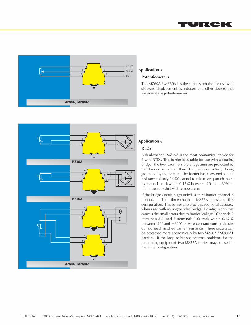
Application 6
RTDs
A dual-channel MZ55A is the most economical choice for3-wire RTDs. This barrier is suitable for use with a floatingbridge - the two leads from the bridge arms are protected bythe barrier with the third lead (supply return) beinggrounded by the barrier. The barrier has a low end-to-endresistance of only 24 Ω/channel to minimize span changes.Its channels track within 0.15 Ω between -20 and +60°C tominimize zero shift with temperature.
If the bridge circuit is grounded, a third barrier channel isneeded. The three-channel MZ56A provides thisconfiguration. This barrier also provides additional accuracywhen used with an ungrounded bridge, a configuration thatcancels the small errors due to barrier leakage. Channels 2(terminals 2-5) and 3 (terminals 3-6) track within 0.15 Ωbetween -20° and +60°C. 4-wire constant-current circuitsdo not need matched barrier resistance. These circuits canbe protected more economically by two MZ60A / MZ60A1barriers. If the loop resistance presents problems for themonitoring equipment, two MZ55A barriers may be used inthe same configuration.
MZ60A, MZ60A1
+7.2 V
0 V
Output
4
5
6
1
2
3
4
5
6
1
2
3
MZ55A
MZ56A
MZ60A, MZ60A1
4
5
6
1
2
3
4
5
6
1
2
3
4
5
6
1
2
3
Application 5
Potentiometers
The MZ60A / MZ60A1 is the simplest choice for use withslidewire displacement transducers and other devices thatare essentially potentiometers.
11 TURCK Inc. 3000 Campus Drive Minneapolis, MN 55441 Application Support: 1-800-544-PROX Fax: (763) 553-0708 www.turck.com
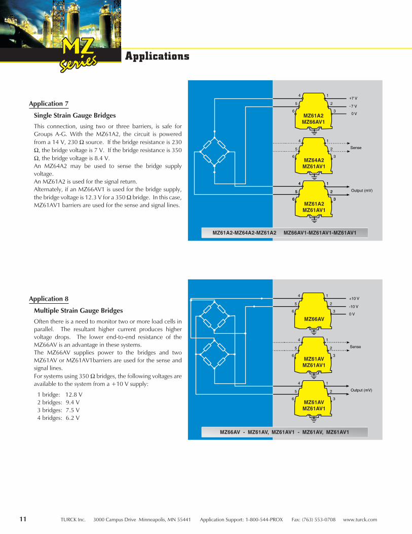
Application 7
Single Strain Gauge Bridges
This connection, using two or three barriers, is safe forGroups A-G. With the MZ61A2, the circuit is poweredfrom a 14 V, 230 Ω source. If the bridge resistance is 230Ω, the bridge voltage is 7 V. If the bridge resistance is 350Ω, the bridge voltage is 8.4 V.An MZ64A2 may be used to sense the bridge supplyvoltage.An MZ61A2 is used for the signal return.Alternately, if an MZ66AV1 is used for the bridge supply,the bridge voltage is 12.3 V for a 350 Ω bridge. In this case,MZ61AV1 barriers are used for the sense and signal lines.
MZ61A2-MZ64A2-MZ61A2 MZ66AV1-MZ61AV1-MZ61AV1
MZ61A2MZ66AV1
MZ64A2MZ61AV1
MZ61A2MZ61AV1
Applications
MZ61AVMZ61AV1
MZ66AV
MZ61AVMZ61AV1
MZ66AV - MZ61AV, MZ61AV1 - MZ61AV, MZ61AV1
Application 8
Multiple Strain Gauge Bridges
Often there is a need to monitor two or more load cells inparallel. The resultant higher current produces highervoltage drops. The lower end-to-end resistance of theMZ66AV is an advantage in these systems.The MZ66AV supplies power to the bridges and twoMZ61AV or MZ61AV1barriers are used for the sense andsignal lines.For systems using 350 Ω bridges, the following voltages areavailable to the system from a +10 V supply:
1 bridge: 12.8 V2 bridges: 9.4 V3 bridges: 7.5 V4 bridges: 6.2 V

TURCK Inc. 3000 Campus Drive Minneapolis, MN 55441 Application Support: 1-800-544-PROX Fax: (763) 553-0708 www.turck.com 12
Application 9
Controller Outputs (I/P Converters)
The single-channel MZ28P / MZ28P1 is the recommendedchoice for most controller outputs. Its end-to-endresistance of 332 / 342 Ω, producing voltage drops of 6.7 V /6.9 V at 20 mA, is compatible with most modernequipment. Higher-power versions are also available: theMZ28PX1 (275 Ω, 5.5 V drop) is suitable for Group A-Glocations; the MZ29PX1 (211 Ω, 4.2 V drop) is suitable forGroup C-G locations. For controllers in which the controlelement is located in the return leg, the dual-channelMZ87P / MZ87P1 is recommended, as the 26 V returnchannel allows the control signal to be completely turnedoff. Its voltage drop is 8.2 V / 8.6 V at 20 mA. Ahigher-power version, the MZ87PX / MZ87PX1 (6.72 V /7.24 V drop) is also available and is suitable for GroupA-G locations.
MZ28P, MZ28P1, MZ28PX1, MZ29PX1*
MZ87P, MZ87P1, MZ87PX, MZ87PX1
MZ87P, MZ87P1, MZ07P2
MZ28P, MZ28P1, MZ28PX1, MZ29PX1*
MZ87P, MZ87P1, MZ87PX, MZ87PX1, MZ08P2
LED,
Alarm
LED,
Alarm
Application 11
Discrete Outputs(Solenoid Valves, LEDs, Alarms, etc.)
The MZ28P / MZ28P1 is recommended for systems inwhich the control switch is in the supply leg.Higher- powered versions are available: the MZ28PX1 issuitable for Group A-G locations: the MZ29PX1 is suitablefor Group C-G locations.
For systems in which the control switch is in the return leg,the dual-channel MZ87P / MZ87P1 is recommended, oralternately, the higher-power MZ87PX / MZ87PX1.For systems without closely regulated supply voltage, theMZ08P2 is recommended.
Application 10
Discrete Inputs (Dry Contacts)
The dual-channel MZ87P / MZ87P1 is the recommendedchoice in systems with a closely regulated supply.The active MZ07P2 is recommended when the supply isnot closely regulated (up to 35 V).