Embed Size (px)
Citation preview

INS
TRU
CTIO
NM
AN
UA
LLimited Edition 3H.P. Left Tilt Unisaw® with
52" Unifence®
(Model 36-842)36-842 Consists of:
36-869 Base Unit36-937 10" Cast Iron Wings (2)
36-918 (52") Unifence Assembly36-947 Gray table boards
36-904 Unifence front rail with stop35-617 Carbide blade
50-289 Mobile Base36-862 Zero Clearance Insert
PART NO. 422-40-651-0012 - 10-16-02Copyright © 2002 Delta Machinery
To learn more about DELTA MACHINERY visit our website at: www.deltamachinery.com.For Parts, Service, Warranty or other Assistance,
please call 1-800-223-7278 (In Canada call 1-800-463-3582).
Limited Edition 3 H.P. Left Tilt Unisaw® with50" Commercial Biesemeyer® Fence System
(Model 36-844)36-844 Consists of:
36-869 Base Unit36-937 10" Cast Iron Wings (2)
78-995 50" Biesemeyer Rail System78-924 Gray Table Board
35-617 Carbide Blade50-289 Mobile Base
36-862 Zero Clearance Insert78-996 Commercial Fence with Legs
Limited Edition 5 H.P. Left Tilt Unisaw® with50" Commercial Biesemeyer® Fence System
(Model 36-845)36-845 Consists of:
34-855 Base Unit36-937 10" Cast Iron Wings (2)
78-995 50" Biesemeyer Rail System78-924 Gray Table Board
35-617, 35-611, 35-616, Carbide Blades36-862 Zero Clearance Insert
78-996 Commercial Fence with Legs78-969 Rear Support Table
2
GENERAL SAFETY RULESWoodworking can be dangerous if safe and proper operating procedures are not followed. As with all machinery, thereare certain hazards involved with the operation of the product. Using the machine with respect and caution willconsiderably lessen the possibility of personal injury. However, if normal safety precautions are overlooked or ignored,personal injury to the operator may result. Safety equipment such as guards, push sticks, hold-downs, featherboards,goggles, dust masks and hearing protection can reduce your potential for injury. But even the best guard won’t makeup for poor judgment, carelessness or inattention. Always use common sense and exercise caution in the workshop.If a procedure feels dangerous, don’t try it. Figure out an alternative procedure that feels safer. REMEMBER: Yourpersonal safety is your responsibility.
This machine was designed for certain applications only. Delta Machinery strongly recommends that this machine notbe modified and/or used for any application other than that for which it was designed. If you have any questions relativeto a particular application, DO NOT use the machine until you have first contacted Delta to determine if it can or shouldbe performed on the product.
Technical Service ManagerDelta Machinery4825 Highway 45 NorthJackson, TN 38305
(IN CANADA: 505 SOUTHGATE DRIVE, GUELPH, ONTARIO N1H 6M7)
WARNING: FAILURE TO FOLLOW THESE RULES MAY RESULT IN SERIOUS PERSONAL INJURY
1. FOR YOUR OWN SAFETY, READ INSTRUCTIONMANUAL BEFORE OPERATING THE TOOL. Learn thetool’s application and limitations as well as the specifichazards peculiar to it.
2. KEEP GUARDS IN PLACE and in working order.3. ALWAYS WEAR EYE PROTECTION. Wear safety
glasses. Everyday eyeglasses only have impact resistantlenses; they are not safety glasses. Also use face or dustmask if cutting operation is dusty. These safety glassesmust conform to ANSI Z87.1 requirements. NOTE:Approved glasses have Z87 printed or stamped on them.
4. REMOVE ADJUSTING KEYS AND WRENCHES. Formhabit of checking to see that keys and adjusting wrenchesare removed from tool before turning it “on”.
5. KEEP WORK AREA CLEAN. Cluttered areas andbenches invite accidents.
6. DON’T USE IN DANGEROUS ENVIRONMENT. Don’tuse power tools in damp or wet locations, or expose themto rain. Keep work area well-lighted.
7. KEEP CHILDREN AND VISITORS AWAY. All childrenand visitors should be kept a safe distance from work area.
8. MAKE WORKSHOP CHILDPROOF – with padlocks,master switches, or by removing starter keys.
9. DON’T FORCE TOOL. It will do the job better and besafer at the rate for which it was designed.10. USE RIGHT TOOL. Don’t force tool or attachment todo a job for which it was not designed.11. WEAR PROPER APPAREL. No loose clothing, gloves,neckties, rings, bracelets, or other jewelry to get caught inmoving parts. Nonslip footwear is recommended. Wearprotective hair covering to contain long hair.12. SECURE WORK. Use clamps or a vise to hold workwhen practical. It’s safer than using your hand and freesboth hands to operate tool.13. DON’T OVERREACH . Keep proper footing andbalance at all times.14. MAINTAIN TOOLS IN TOP CONDITION. Keep toolssharp and clean for best and safest performance. Followinstructions for lubricating and changing accessories.15. DISCONNECT TOOLS before servicing and whenchanging accessories such as blades, bits, cutters, etc.16. USE RECOMMENDED ACCESSORIES. The use ofaccessories and attachments not recommended by Deltamay cause hazards or risk of injury to persons.17. REDUCE THE RISK OF UNINTENTIONAL STARTING.Make sure switch is in “OFF” position before plugging inpower cord. In the event of a power failure, move switchto the “OFF” position.
18. NEVER STAND ON TOOL. Serious injury could occur ifthe tool is tipped or if the cutting tool is accidentallycontacted.19. CHECK DAMAGED PARTS. Before further use of thetool, a guard or other part that is damaged should becarefully checked to ensure that it will operate properly andperform its intended function – check for alignment ofmoving parts, binding of moving parts, breakage of parts,mounting, and any other conditions that may affect itsoperation. A guard or other part that is damaged should beproperly repaired or replaced.20. DIRECTION OF FEED. Feed work into a blade orcutter against the direction of rotation of the blade or cutteronly.21. NEVER LEAVE TOOL RUNNING UNATTENDED.TURN POWER OFF. Don’t leave tool until it comes to acomplete stop.22. STAY ALERT, WATCH WHAT YOU ARE DOING, ANDUSE COMMON SENSE WHEN OPERATING A POWERTOOL. DO NOT USE TOOL WHILE TIRED OR UNDER THEINFLUENCE OF DRUGS, ALCOHOL, OR MEDICATION. Amoment of inattention while operating power tools may resultin serious personal injury.23. MAKE SURE TOOL IS DISCONNECTED FROMPOWER SUPPLY whi le motor is be ing mounted,connected or reconnected.24. THE DUST GENERATED by certain woods and woodproducts can be injurious to your health. Always operatemachinery in well ventilated areas and provide for properdust removal. Use wood dust collection systems wheneverpossible.25. WARNING: SOME DUST CREATED BYPOWER SANDING, SAWING, GRINDING, DRILLING,AND OTHER CONSTRUCTION ACTIVITIES containschemicals known to cause cancer, birth defects or otherreproductive harm. Some examples of these chemicalsare:· lead from lead-based paints,· crystalline silica from bricks and cement and other
masonry products, and· arsenic and chromium from chemically-treated lumber. Your risk from these exposures varies, depending on howoften you do this type of work. To reduce your exposureto these chemicals: work in a well ventilated area, andwork with approved safety equipment, such as thosedust masks that are specially designed to filter outmicroscopic particles.
SAVE THESE INSTRUCTIONS. Refer to them often and use them to instruct others.
3
ADDITIONAL SAFETY RULES FORTABLE SAWS
1. DO NOT OPERATE THIS MACHINE until it isassembled and installed according to theinstructions.
2. OBTAIN ADVICE FROM YOUR SUPERVISOR,instructor, or another qualified person if you arenot familiar with the operation of this machine.
3. FOLLOW ALL WIRING CODES and recommendedelectrical connections.
4. USE THE GUARDS WHENEVER POSSIBLE.Check to see that they are in place, secured, andworking correctly.
5. AVOID KICKBACK by:A. keeping blade sharp and free of rust and pitch.B. keeping rip fence parallel to the saw blade.C. using saw blade guard and spreader for every
possible operation, including all throughsawing.
D. pushing the workpiece past the saw blade priorto release.
E. never ripping a workpiece that is twisted orwarped, or does not have a straight edge toguide along the fence.
F. using featherboards when the anti-kickbackdevice cannot be used.
G. never sawing a large workpiece that cannot becontrolled.
H. never using the fence as a guide whencrosscutting.
I. never sawing a workpiece with loose knots orother flaws.
6. ALWAYS USE GUARDS, SPLITTER, AND ANTI-KICKBACK FINGERS except when otherwisedirected in the manual.
7. REMOVE CUT-OFF PIECES AND SCRAPS fromthe table before starting the saw. The vibration of themachine may cause them to move into the sawblade and be thrown out. After cutting, turn themachine off. When the blade has come to acomplete stop, remove all debris.
8. NEVER START THE MACHINE with the workpieceagainst the blade.
9. HOLD THE WORKPIECE FIRMLY against the mitergauge or fence.
10. NEVER run the workpiece between the fence and amoulding cutterhead.
11. NEVER perform “free-hand” operations. Use eitherthe fence or miter gauge to position and guide theworkpiece.
12. USE PUSH STICK(S) for ripping a narrowworkpiece.
13. AVOID AWKWARD OPERATIONS AND HANDPOSITIONS where a sudden slip could cause ahand to move into the blade.
14. KEEP ARMS, HANDS, AND FINGERS away fromthe blade.
15. NEVER have any part of your body in line with thepath of the saw blade.
16. NEVER REACH AROUND or over the saw blade.
17. NEVER attempt to free a stalled saw blade withoutfirst turning the machine “OFF”.
18. PROPERLY SUPPORT LONG OR WIDEworkpieces.
19. NEVER PERFORM LAYOUT, assembly or set-upwork on the table/work area when the machine isrunning.
20. TURN THE MACHINE “OFF” AND DISCONNECTTHE MACHINE from the power source beforeinstalling or removing accessories, before adjustingor changing set-ups, or when making repairs.
21. TURN THE MACHINE “OFF”, disconnect themachine from the power source, and clean thetable/work area before leaving the machine. LOCKTHE SWITCH IN THE “OFF” POSITION to preventunauthorized use.
22. ADDITIONAL INFORMATION regarding the safeand proper operation of this tool is available fromthe Power Tool Institute, 1300 Summer Avenue,Cleveland, OH 44115-2851. Information is alsoavailable from the National Safety Council, 1121Spring Lake Drive, Itasca, IL 60143-3201. Pleaserefer to the American National Standards InstituteANSI 01.1 Safety Requirements for WoodworkingMachines and the U.S. Department of Labor OSHA1910.213 Regulations.
WARNING: FAILURE TO FOLLOW THESE RULES MAY RESULT IN SERIOUS PERSONAL INJURY.
SAVE THESE INSTRUCTIONS. Refer to them often
and use them to instruct others.
4
POWER CONNECTIONSA separate electrical circuit should be used for your machines. This circuit should not be less than #12 wire and shouldbe protected with a 20 Amp time lag fuse. If an extension cord is used, use only 3-wire extension cords which have 3-prong grounding type plugs and matching receptacle which will accept the machine’s plug. Before connecting themotor to the power line, make sure the switch is in the “OFF” position and be sure that the electric current is of thesame characteristics as indicated on the machine. All line connections should make good contact. Running on lowvoltage will damage the motor.
WARNING: DO NOT EXPOSE THE MACHINE TO RAIN OR OPERATE THE MACHINE IN DAMP LOCATIONS.
MOTOR SPECIFICATIONSYour machine is wired for 230 volt, 60 HZ alternating current. Before connecting the machine to the power source,make sure the switch is in the “OFF” position.
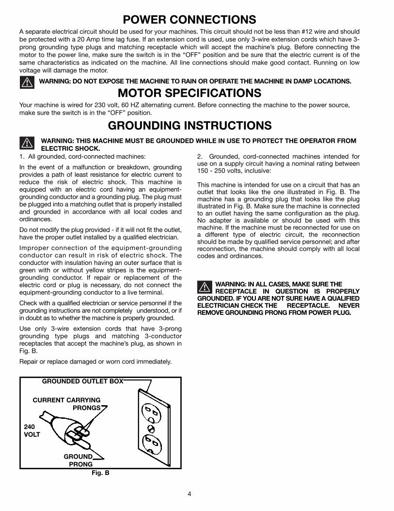
GROUNDING INSTRUCTIONSWARNING: THIS MACHINE MUST BE GROUNDED WHILE IN USE TO PROTECT THE OPERATOR FROMELECTRIC SHOCK.
2. Grounded, cord-connected machines intended foruse on a supply circuit having a nominal rating between150 - 250 volts, inclusive:
This machine is intended for use on a circuit that has anoutlet that looks like the one illustrated in Fig. B. Themachine has a grounding plug that looks like the plugillustrated in Fig. B. Make sure the machine is connectedto an outlet having the same configuration as the plug.No adapter is available or should be used with thismachine. If the machine must be reconnected for use ona different type of electric circuit, the reconnectionshould be made by qualified service personnel; and afterreconnection, the machine should comply with all localcodes and ordinances.
WARNING: IN ALL CASES, MAKE SURE THE RECEPTACLE IN QUESTION IS PROPERLY
GROUNDED. IF YOU ARE NOT SURE HAVE A QUALIFIEDELECTRICIAN CHECK THE RECEPTACLE. NEVERREMOVE GROUNDING PRONG FROM POWER PLUG.
1. All grounded, cord-connected machines:
In the event of a malfunction or breakdown, groundingprovides a path of least resistance for electric current toreduce the risk of electric shock. This machine isequipped with an electric cord having an equipment-grounding conductor and a grounding plug. The plug mustbe plugged into a matching outlet that is properly installedand grounded in accordance with all local codes andordinances.
Do not modify the plug provided - if it will not fit the outlet,have the proper outlet installed by a qualified electrician.
Improper connection of the equipment-groundingconductor can result in risk of electric shock. Theconductor with insulation having an outer surface that isgreen with or without yellow stripes is the equipment-grounding conductor. If repair or replacement of theelectric cord or plug is necessary, do not connect theequipment-grounding conductor to a live terminal.
Check with a qualified electrician or service personnel if thegrounding instructions are not completely understood, or ifin doubt as to whether the machine is properly grounded.
Use only 3-wire extension cords that have 3-pronggrounding type plugs and matching 3-conductorreceptacles that accept the machine’s plug, as shown inFig. B.
Repair or replace damaged or worn cord immediately.
Fig. B
CURRENT CARRYINGPRONGS
GROUNDED OUTLET BOX
GROUNDPRONG
240VOLT
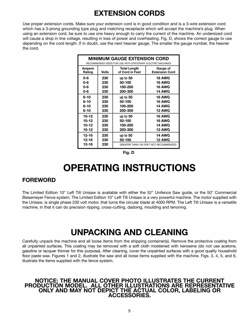
Use proper extension cords. Make sure your extension cord is in good condition and is a 3-wire extension cordwhich has a 3-prong grounding type plug and matching receptacle which will accept the machine’s plug. Whenusing an extension cord, be sure to use one heavy enough to carry the current of the machine. An undersized cordwill cause a drop in line voltage, resulting in loss of power and overheating. Fig. D, shows the correct gauge to usedepending on the cord length. If in doubt, use the next heavier gauge. The smaller the gauge number, the heavierthe cord.
EXTENSION CORDS
OPERATING INSTRUCTIONSFOREWORD
The Limited Edition 10" Left Tilt Unisaw is available with either the 52" Unifence Saw guide, or the 50" CommercialBiesemeyer Fence system. The Limited Edition 10" Left Tilt Unisaw is a very powerful machine. The motor supplied withthe Unisaw, is single phase 230 volt motor, that turns the circular blade at 4000 RPM. The Left Tilt Unisaw is a versatilemachine, in that it can do precision ripping, cross-cutting, dadoing, moulding and tenoning.
UNPACKING AND CLEANINGCarefully unpack the machine and all loose items from the shipping container(s). Remove the protective coating fromall unpainted surfaces. This coating may be removed with a soft cloth moistened with kerosene (do not use acetone,gasoline or lacquer thinner for this purpose). After cleaning, cover the unpainted surfaces with a good quality householdfloor paste wax. Figures 1 and 2, illustrate the saw and all loose items supplied with the machine. Figs. 3, 4, 5, and 6,illustrate the items supplied with the fence system.
NOTICE: THE MANUAL COVER PHOTO ILLUSTRATES THE CURRENTPRODUCTION MODEL. ALL OTHER ILLUSTRATIONS ARE REPRESENTATIVE
ONLY AND MAY NOT DEPICT THE ACTUAL COLOR, LABELING ORACCESSORIES.
5
Fig. D
MINIMUM GAUGE EXTENSION CORDRECOMMENDED SIZES FOR USE WITH STATIONARY ELECTRIC MACHINES
Ampere Total Length Gauge ofRating Volts of Cord in Feet Extension Cord
0-6 230 up to 50 18 AWG0-6 230 50-100 16 AWG0-6 230 100-200 16 AWG0-6 230 200-300 14 AWG
6-10 230 up to 50 18 AWG6-10 230 50-100 16 AWG6-10 230 100-200 14 AWG6-10 230 200-300 12 AWG
10-12 230 up to 50 16 AWG10-12 230 50-100 16 AWG10-12 230 100-200 14 AWG10-12 230 200-300 12 AWG
12-16 230 up to 50 14 AWG12-16 230 50-100 12 AWG12-16 230 GREATER THAN 100 FEET NOT RECOMMENDED
6
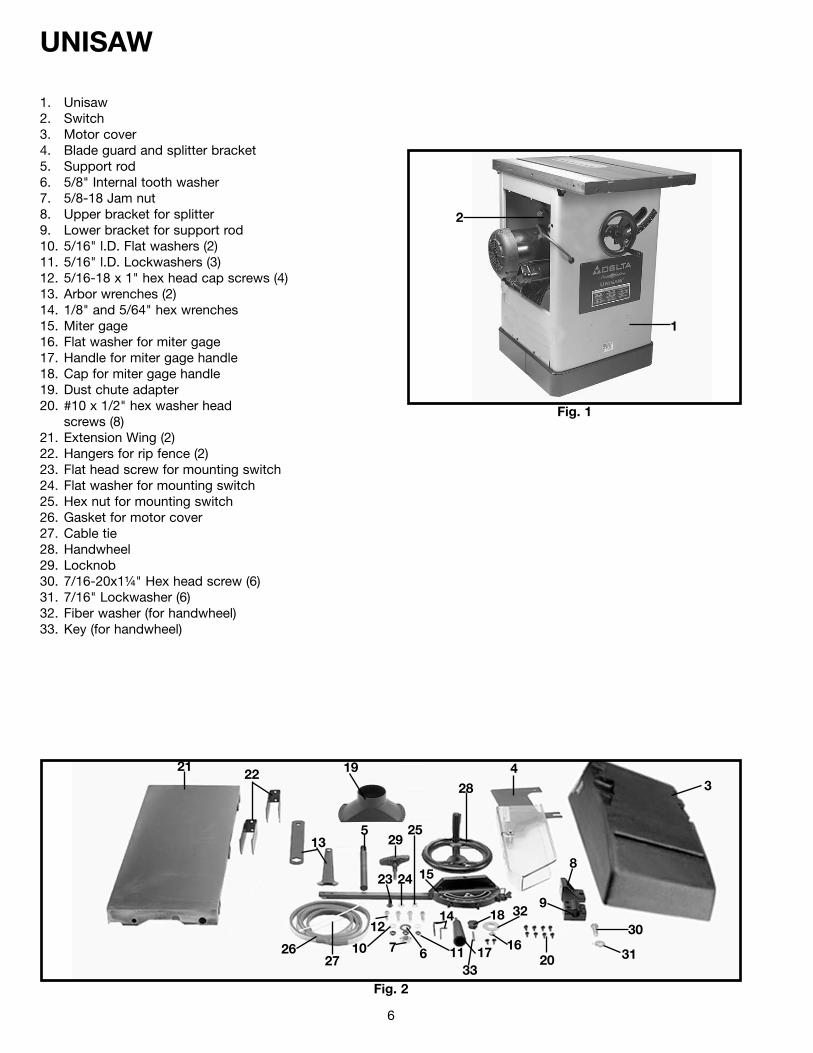
Fig. 1
UNISAW
1. Unisaw2. Switch3. Motor cover4. Blade guard and splitter bracket5. Support rod6. 5/8" Internal tooth washer7. 5/8-18 Jam nut8. Upper bracket for splitter9. Lower bracket for support rod10. 5/16" l.D. Flat washers (2)11. 5/16" l.D. Lockwashers (3)12. 5/16-18 x 1" hex head cap screws (4)13. Arbor wrenches (2)14. 1/8" and 5/64" hex wrenches15. Miter gage16. Flat washer for miter gage17. Handle for miter gage handle18. Cap for miter gage handle19. Dust chute adapter20. #10 x 1/2" hex washer head
screws (8)21. Extension Wing (2)22. Hangers for rip fence (2)23. Flat head screw for mounting switch24. Flat washer for mounting switch25. Hex nut for mounting switch26. Gasket for motor cover27. Cable tie28. Handwheel29. Locknob30. 7/16-20x1¼" Hex head screw (6)31. 7/16" Lockwasher (6)32. Fiber washer (for handwheel)33. Key (for handwheel)
Fig. 2
1
2
34
5
67
8
9
10 11
12
13
14
15
1617
18
19
20
2122
23 24
25
2627
28
29
31
3032
33
7
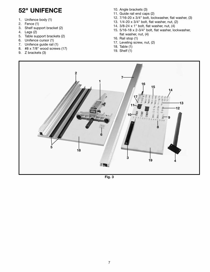
52" UNIFENCE1. Unifence body (1)2. Fence (1)3. Shelf support bracket (2)4. Legs (2)5. Table support brackets (2)6. Unifence cursor (1)7. Unifence guide rail (1)8. #8 x 7/8" wood screws (17)9. Z brackets (3)
10. Angle brackets (3)11. Guide rail end caps (2)12. 7/16-20 x 3/4" bolt, lockwasher, flat washer, (3)13. 1/4-20 x 3/4" bolt, flat washer, nut, (2)14. 3/8-24 x 1" bolt, flat washer, nut, (4)15. 5/16-18 x 2-3/4" bolt, flat washer, lockwasher,
flat washer, nut, (4)16. Rail stop (1)17. Leveling screw, nut, (2) 18. Table (1)19. Shelf (1)
1
2
34
5
6
7
8
910
1112
13
1415
16
17
18
19
Fig. 3
8
Fig. 4
Fig. 5 Fig. 6
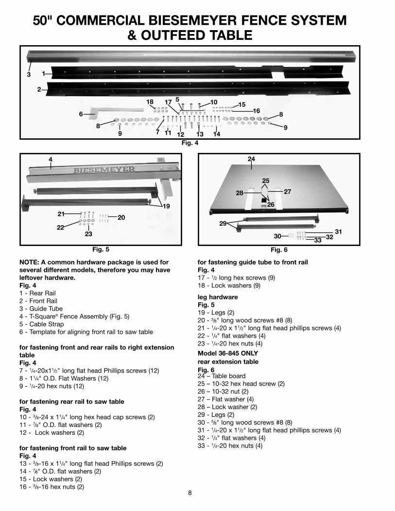
50" COMMERCIAL BIESEMEYER FENCE SYSTEM& OUTFEED TABLE
NOTE: A common hardware package is used for several different models, therefore you may have leftover hardware.Fig. 41 - Rear Rail2 - Front Rail3 - Guide Tube4 - T-Square® Fence Assembly (Fig. 5)5 - Cable Strap6 - Template for aligning front rail to saw table
for fastening front and rear rails to right extensiontableFig. 47 - 1/4-20x11/2" long flat head Phillips screws (12)8 - 11/4" O.D. Flat Washers (12)9 - 1/4-20 hex nuts (12)
for fastening rear rail to saw tableFig. 410 - 3/8-24 x 11/4" long hex head cap screws (2)11 - 7/8" O.D. flat washers (2)12 - Lock washers (2)
for fastening front rail to saw tableFig. 413 - 3/8-16 x 11/4" long flat head Phillips screws (2)14 - 7/8" O.D. flat washers (2)15 - Lock washers (2)16 - 3/8-16 hex nuts (2)
for fastening guide tube to front railFig. 417 - 1/2 long hex screws (9)18 - Lock washers (9)
leg hardwareFig. 519 - Legs (2)20 - 5/8" long wood screws #8 (8)21 - 1/4-20 x 11/2" long flat head phillips screws (4)22 - 1/4" flat washers (4)23 - 1/4-20 hex nuts (4)
Model 36-845 ONLY rear extension table Fig. 624 – Table board25 – 10-32 hex head screw (2)26 – 10-32 nut (2)27 – Flat washer (4)28 – Lock washer (2)29 - Legs (2)30 - 5/8" long wood screws #8 (8)31 - 1/4-20 x 11/2" long flat head phillips screws (4)32 - 1/4" flat washers (4)33 - 1/4-20 hex nuts (4)
1
2
3
4
5
6
78
9
10
11 12 13 14
1516
1718
19
8
9
2021
2223
24
25
26
2728
29
3031
3233
9
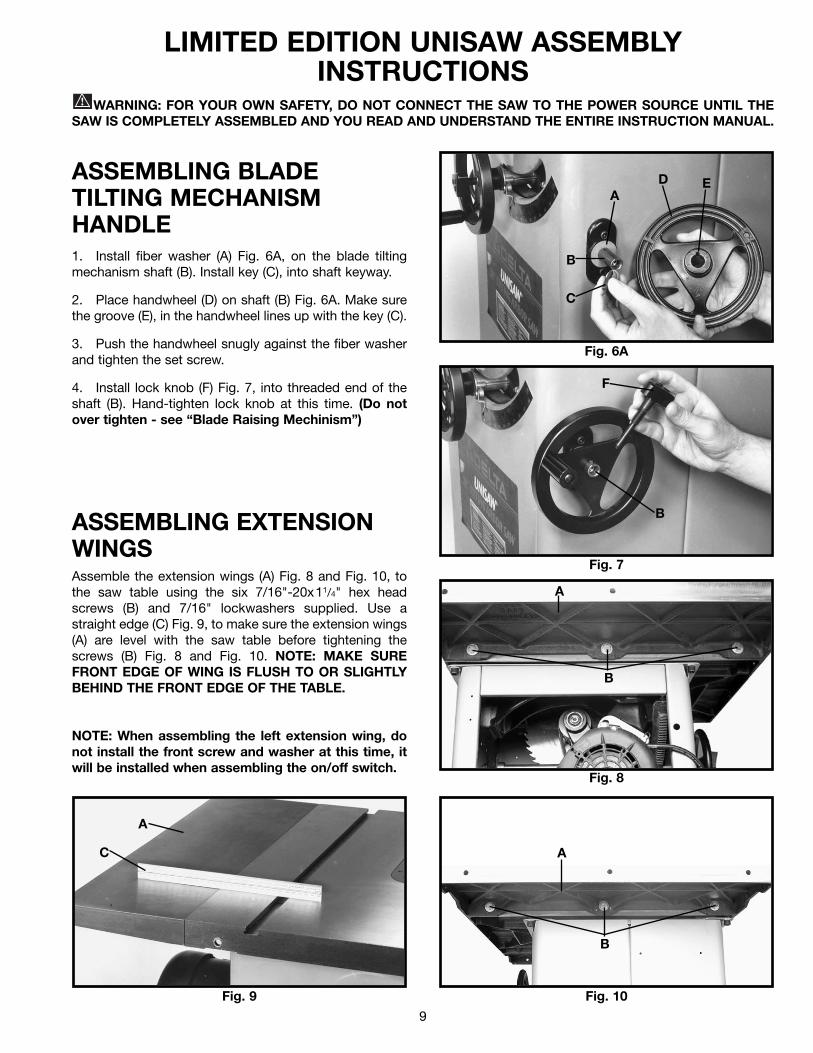
LIMITED EDITION UNISAW ASSEMBLYINSTRUCTIONS
WARNING: FOR YOUR OWN SAFETY, DO NOT CONNECT THE SAW TO THE POWER SOURCE UNTIL THESAW IS COMPLETELY ASSEMBLED AND YOU READ AND UNDERSTAND THE ENTIRE INSTRUCTION MANUAL.
ASSEMBLING BLADETILTING MECHANISMHANDLE1. Install fiber washer (A) Fig. 6A, on the blade tiltingmechanism shaft (B). Install key (C), into shaft keyway.
2. Place handwheel (D) on shaft (B) Fig. 6A. Make surethe groove (E), in the handwheel lines up with the key (C).
3. Push the handwheel snugly against the fiber washerand tighten the set screw.
4. Install lock knob (F) Fig. 7, into threaded end of theshaft (B). Hand-tighten lock knob at this time. (Do notover tighten - see “Blade Raising Mechinism”)
ASSEMBLING EXTENSIONWINGSAssemble the extension wings (A) Fig. 8 and Fig. 10, tothe saw table using the six 7/16"-20x11/4" hex headscrews (B) and 7/16" lockwashers supplied. Use astraight edge (C) Fig. 9, to make sure the extension wings(A) are level with the saw table before tightening thescrews (B) Fig. 8 and Fig. 10. NOTE: MAKE SUREFRONT EDGE OF WING IS FLUSH TO OR SLIGHTLYBEHIND THE FRONT EDGE OF THE TABLE.
NOTE: When assembling the left extension wing, donot install the front screw and washer at this time, itwill be installed when assembling the on/off switch.
Fig. 6A
Fig. 7
Fig. 8
Fig. 9 Fig. 10
A
B
C
D E
F
B
A
B
A
C A
B
10
Fig. 11 Fig. 12
Fig. 13
Fig. 14
Fig. 15
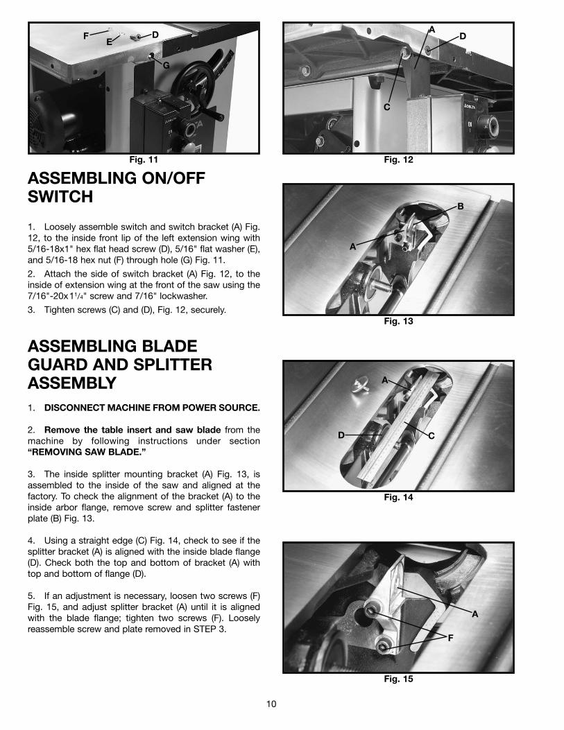
ASSEMBLING ON/OFFSWITCH
1. Loosely assemble switch and switch bracket (A) Fig.12, to the inside front lip of the left extension wing with5/16-18x1" hex flat head screw (D), 5/16" flat washer (E),and 5/16-18 hex nut (F) through hole (G) Fig. 11.
2. Attach the side of switch bracket (A) Fig. 12, to theinside of extension wing at the front of the saw using the7/16"-20x11/4" screw and 7/16" lockwasher.
3. Tighten screws (C) and (D), Fig. 12, securely.
ASSEMBLING BLADEGUARD AND SPLITTERASSEMBLY1. DISCONNECT MACHINE FROM POWER SOURCE.
2. Remove the table insert and saw blade from themachine by following instructions under section“REMOVING SAW BLADE.”
3. The inside splitter mounting bracket (A) Fig. 13, isassembled to the inside of the saw and aligned at thefactory. To check the alignment of the bracket (A) to theinside arbor flange, remove screw and splitter fastenerplate (B) Fig. 13.
4. Using a straight edge (C) Fig. 14, check to see if thesplitter bracket (A) is aligned with the inside blade flange(D). Check both the top and bottom of bracket (A) withtop and bottom of flange (D).
5. If an adjustment is necessary, loosen two screws (F)Fig. 15, and adjust splitter bracket (A) until it is alignedwith the blade flange; tighten two screws (F). Looselyreassemble screw and plate removed in STEP 3.
G
DE
F
C
DA
A
B
A
CD
A
F
11
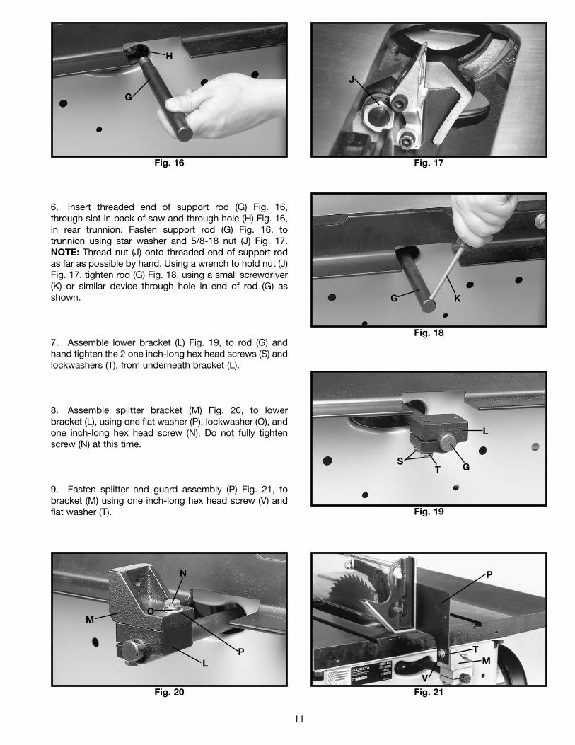
Fig. 16 Fig. 17
Fig. 20 Fig. 21
Fig. 18
Fig. 19
6. Insert threaded end of support rod (G) Fig. 16,through slot in back of saw and through hole (H) Fig. 16,in rear trunnion. Fasten support rod (G) Fig. 16, totrunnion using star washer and 5/8-18 nut (J) Fig. 17.NOTE: Thread nut (J) onto threaded end of support rodas far as possible by hand. Using a wrench to hold nut (J)Fig. 17, tighten rod (G) Fig. 18, using a small screwdriver(K) or similar device through hole in end of rod (G) asshown.
7. Assemble lower bracket (L) Fig. 19, to rod (G) andhand tighten the 2 one inch-long hex head screws (S) andlockwashers (T), from underneath bracket (L).
8. Assemble splitter bracket (M) Fig. 20, to lowerbracket (L), using one flat washer (P), lockwasher (O), andone inch-long hex head screw (N). Do not fully tightenscrew (N) at this time.
9. Fasten splitter and guard assembly (P) Fig. 21, tobracket (M) using one inch-long hex head screw (V) andflat washer (T).
G
H
J
G K
SG
L
M
N
L M
V
P
O
P
T
T
12
Fig. 22
Fig. 23
Fig. 25
Fig. 24
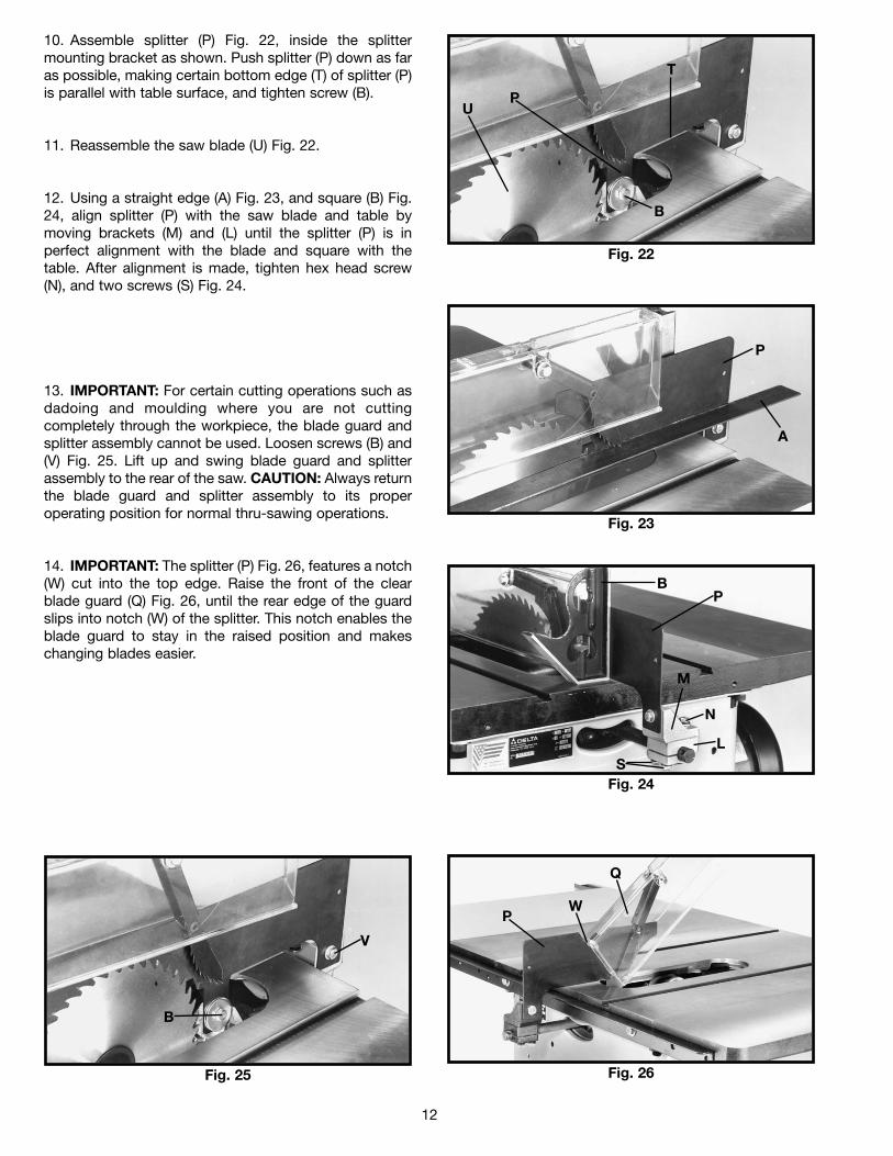
10. Assemble splitter (P) Fig. 22, inside the splittermounting bracket as shown. Push splitter (P) down as faras possible, making certain bottom edge (T) of splitter (P)is parallel with table surface, and tighten screw (B).
11. Reassemble the saw blade (U) Fig. 22.
12. Using a straight edge (A) Fig. 23, and square (B) Fig.24, align splitter (P) with the saw blade and table bymoving brackets (M) and (L) until the splitter (P) is inperfect alignment with the blade and square with thetable. After alignment is made, tighten hex head screw(N), and two screws (S) Fig. 24.
13. IMPORTANT: For certain cutting operations such asdadoing and moulding where you are not cuttingcompletely through the workpiece, the blade guard andsplitter assembly cannot be used. Loosen screws (B) and(V) Fig. 25. Lift up and swing blade guard and splitterassembly to the rear of the saw. CAUTION: Always returnthe blade guard and splitter assembly to its properoperating position for normal thru-sawing operations.
14. IMPORTANT: The splitter (P) Fig. 26, features a notch(W) cut into the top edge. Raise the front of the clearblade guard (Q) Fig. 26, until the rear edge of the guardslips into notch (W) of the splitter. This notch enables theblade guard to stay in the raised position and makeschanging blades easier.
P
T
P
A
BP
N
M
SL
B
V
Fig. 26
PW
B
U
Q
13
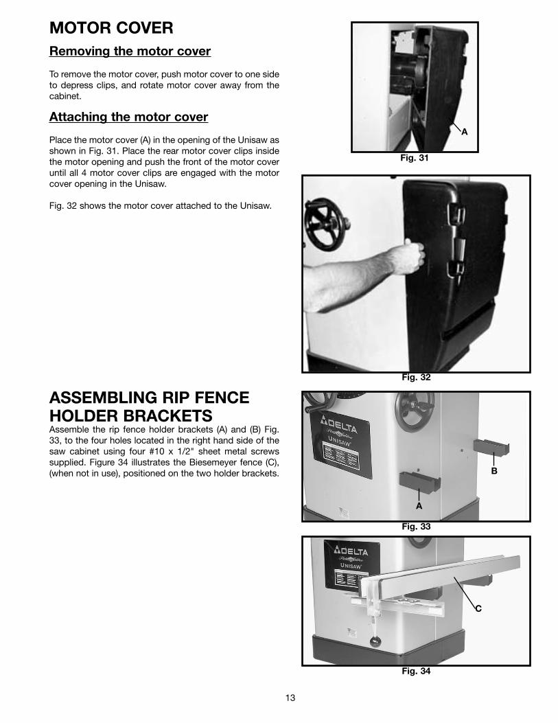
MOTOR COVER Removing the motor cover
To remove the motor cover, push motor cover to one sideto depress clips, and rotate motor cover away from thecabinet.
Attaching the motor cover
Place the motor cover (A) in the opening of the Unisaw asshown in Fig. 31. Place the rear motor cover clips insidethe motor opening and push the front of the motor coveruntil all 4 motor cover clips are engaged with the motorcover opening in the Unisaw.
Fig. 32 shows the motor cover attached to the Unisaw.
Fig. 31
A
Fig. 32
Fig. 33
A
B
Fig. 34
C
ASSEMBLING RIP FENCEHOLDER BRACKETSAssemble the rip fence holder brackets (A) and (B) Fig.33, to the four holes located in the right hand side of thesaw cabinet using four #10 x 1/2" sheet metal screwssupplied. Figure 34 illustrates the Biesemeyer fence (C),(when not in use), positioned on the two holder brackets.
14
ASSEMBLY INSTRUCTIONS FOR MODEL 36-84252" UNIFENCE
Fig. 35
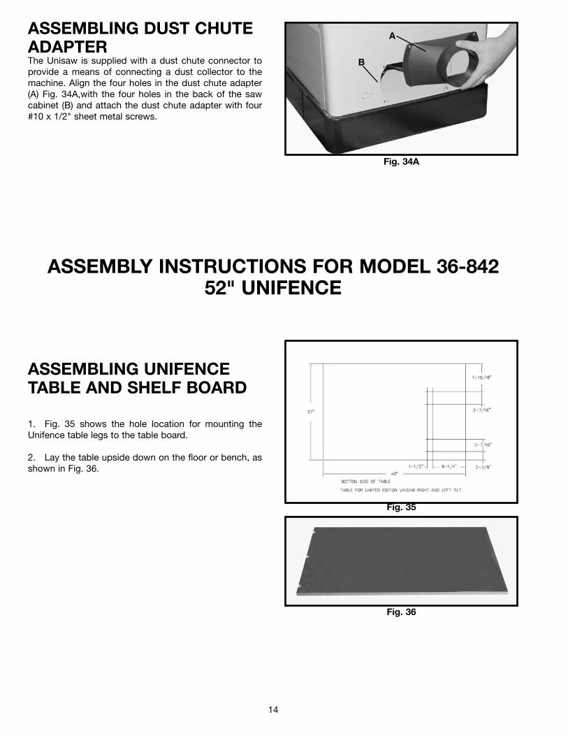
1. Fig. 35 shows the hole location for mounting theUnifence table legs to the table board.
2. Lay the table upside down on the floor or bench, asshown in Fig. 36.
Fig. 36
ASSEMBLING UNIFENCETABLE AND SHELF BOARD
ASSEMBLING DUST CHUTEADAPTERThe Unisaw is supplied with a dust chute connector toprovide a means of connecting a dust collector to themachine. Align the four holes in the dust chute adapter(A) Fig. 34A,with the four holes in the back of the sawcabinet (B) and attach the dust chute adapter with four#10 x 1/2" sheet metal screws.
Fig. 34A
A
B
15
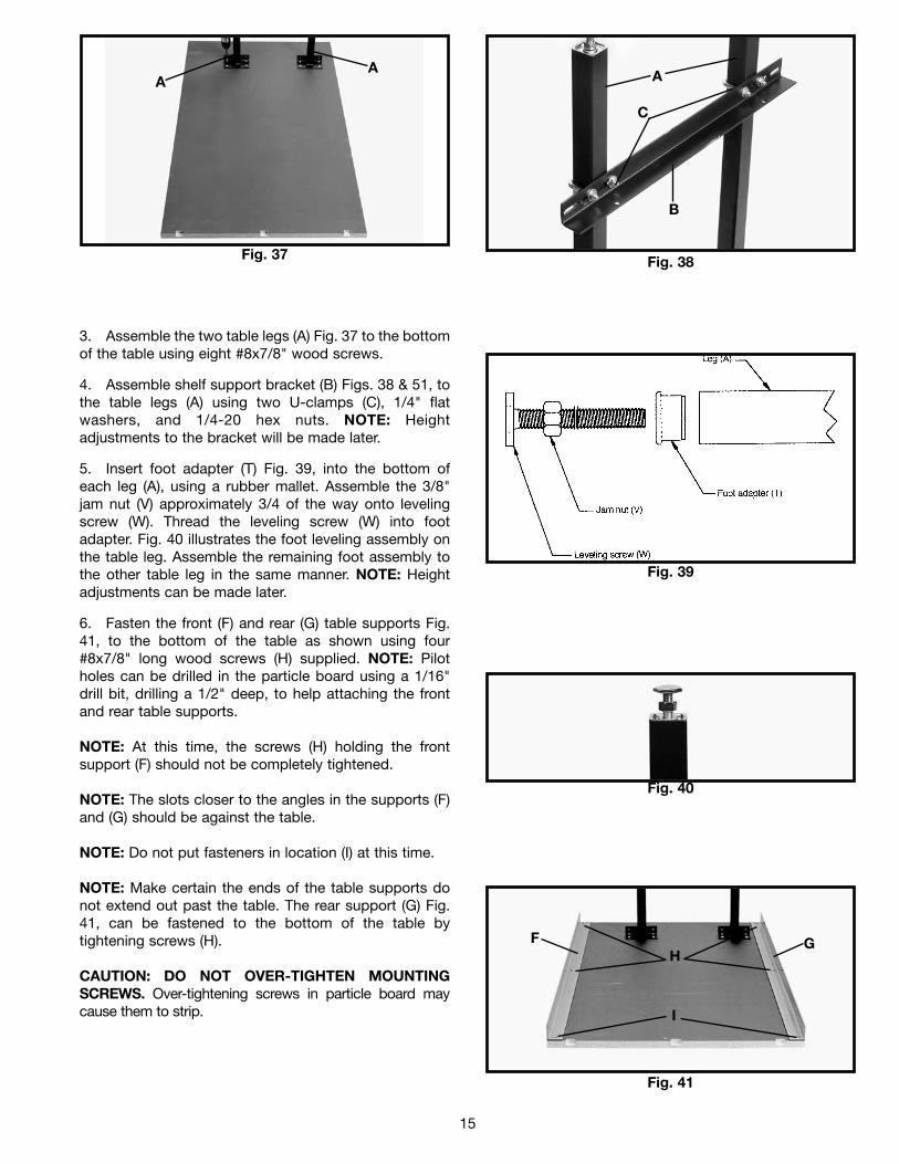
3. Assemble the two table legs (A) Fig. 37 to the bottomof the table using eight #8x7/8" wood screws.
4. Assemble shelf support bracket (B) Figs. 38 & 51, tothe table legs (A) using two U-clamps (C), 1/4" flatwashers, and 1/4-20 hex nuts. NOTE: Heightadjustments to the bracket will be made later.
5. Insert foot adapter (T) Fig. 39, into the bottom ofeach leg (A), using a rubber mallet. Assemble the 3/8"jam nut (V) approximately 3/4 of the way onto levelingscrew (W). Thread the leveling screw (W) into footadapter. Fig. 40 illustrates the foot leveling assembly onthe table leg. Assemble the remaining foot assembly tothe other table leg in the same manner. NOTE: Heightadjustments can be made later.
6. Fasten the front (F) and rear (G) table supports Fig.41, to the bottom of the table as shown using four#8x7/8" long wood screws (H) supplied. NOTE: Pilotholes can be drilled in the particle board using a 1/16"drill bit, drilling a 1/2" deep, to help attaching the frontand rear table supports.
NOTE: At this time, the screws (H) holding the frontsupport (F) should not be completely tightened.
NOTE: The slots closer to the angles in the supports (F)and (G) should be against the table.
NOTE: Do not put fasteners in location (I) at this time.
NOTE: Make certain the ends of the table supports donot extend out past the table. The rear support (G) Fig.41, can be fastened to the bottom of the table bytightening screws (H).
CAUTION: DO NOT OVER-TIGHTEN MOUNTINGSCREWS. Over-tightening screws in particle board maycause them to strip.
Fig. 37
AA
Fig. 38
B
A
C
Fig. 39
Fig. 40
Fig. 41
GFH
I
16
Fig. 42
JK
L
Fig. 43
M
J
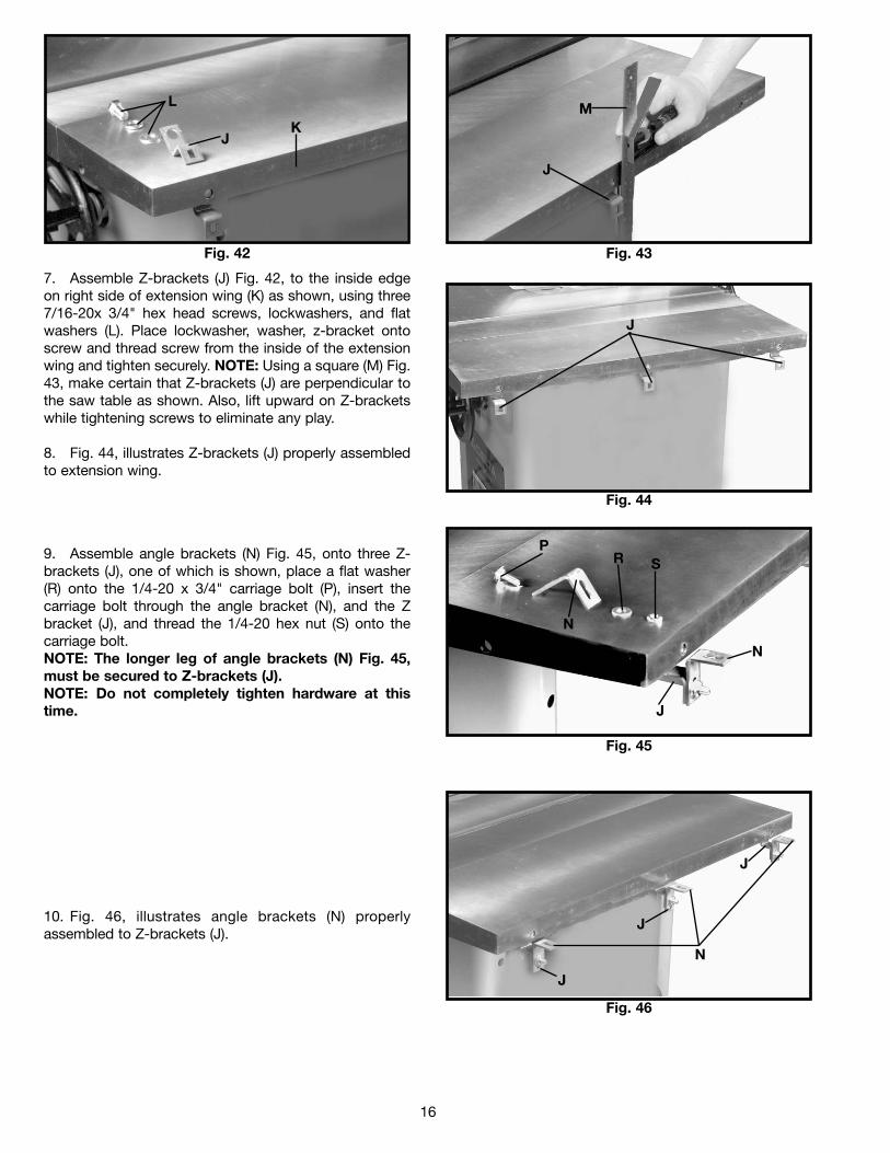
7. Assemble Z-brackets (J) Fig. 42, to the inside edgeon right side of extension wing (K) as shown, using three7/16-20x 3/4" hex head screws, lockwashers, and flatwashers (L). Place lockwasher, washer, z-bracket ontoscrew and thread screw from the inside of the extensionwing and tighten securely. NOTE: Using a square (M) Fig.43, make certain that Z-brackets (J) are perpendicular tothe saw table as shown. Also, lift upward on Z-bracketswhile tightening screws to eliminate any play.
8. Fig. 44, illustrates Z-brackets (J) properly assembledto extension wing.
9. Assemble angle brackets (N) Fig. 45, onto three Z-brackets (J), one of which is shown, place a flat washer(R) onto the 1/4-20 x 3/4" carriage bolt (P), insert thecarriage bolt through the angle bracket (N), and the Zbracket (J), and thread the 1/4-20 hex nut (S) onto thecarriage bolt. NOTE: The longer leg of angle brackets (N) Fig. 45,must be secured to Z-brackets (J).NOTE: Do not completely tighten hardware at thistime.
10. Fig. 46, illustrates angle brackets (N) properlyassembled to Z-brackets (J).
Fig. 44
J
Fig. 45
N
P
Fig. 46
J
N
N
J
J
J
R S
17
Fig. 47
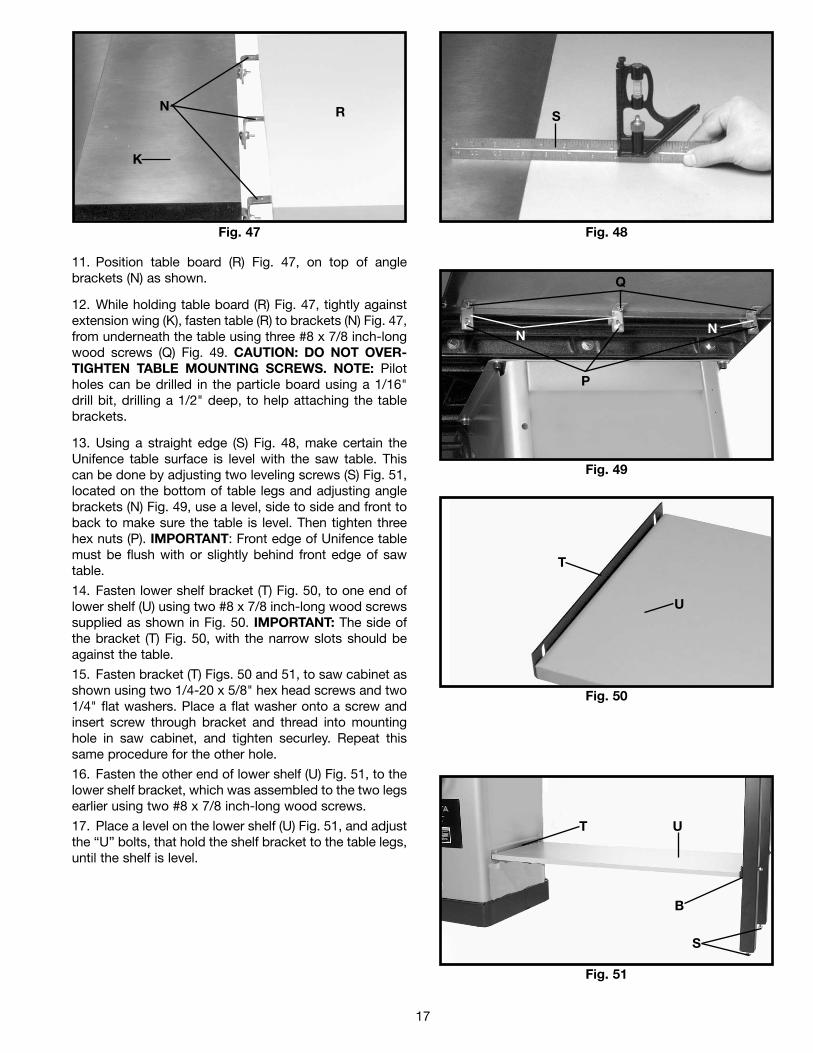
11. Position table board (R) Fig. 47, on top of anglebrackets (N) as shown.
12. While holding table board (R) Fig. 47, tightly againstextension wing (K), fasten table (R) to brackets (N) Fig. 47,from underneath the table using three #8 x 7/8 inch-longwood screws (Q) Fig. 49. CAUTION: DO NOT OVER-TIGHTEN TABLE MOUNTING SCREWS. NOTE: Pilotholes can be drilled in the particle board using a 1/16"drill bit, drilling a 1/2" deep, to help attaching the tablebrackets.
13. Using a straight edge (S) Fig. 48, make certain theUnifence table surface is level with the saw table. Thiscan be done by adjusting two leveling screws (S) Fig. 51,located on the bottom of table legs and adjusting anglebrackets (N) Fig. 49, use a level, side to side and front toback to make sure the table is level. Then tighten threehex nuts (P). IMPORTANT: Front edge of Unifence tablemust be flush with or slightly behind front edge of sawtable.
14. Fasten lower shelf bracket (T) Fig. 50, to one end oflower shelf (U) using two #8 x 7/8 inch-long wood screwssupplied as shown in Fig. 50. IMPORTANT: The side ofthe bracket (T) Fig. 50, with the narrow slots should beagainst the table.
15. Fasten bracket (T) Figs. 50 and 51, to saw cabinet asshown using two 1/4-20 x 5/8" hex head screws and two1/4" flat washers. Place a flat washer onto a screw andinsert screw through bracket and thread into mountinghole in saw cabinet, and tighten securley. Repeat thissame procedure for the other hole.
16. Fasten the other end of lower shelf (U) Fig. 51, to thelower shelf bracket, which was assembled to the two legsearlier using two #8 x 7/8 inch-long wood screws.
17. Place a level on the lower shelf (U) Fig. 51, and adjustthe “U” bolts, that hold the shelf bracket to the table legs,until the shelf is level.
Fig. 48
Fig. 49
N
K
R S
Q
P
Fig. 50
Fig. 51
T
U
T U
N N
S
B
18
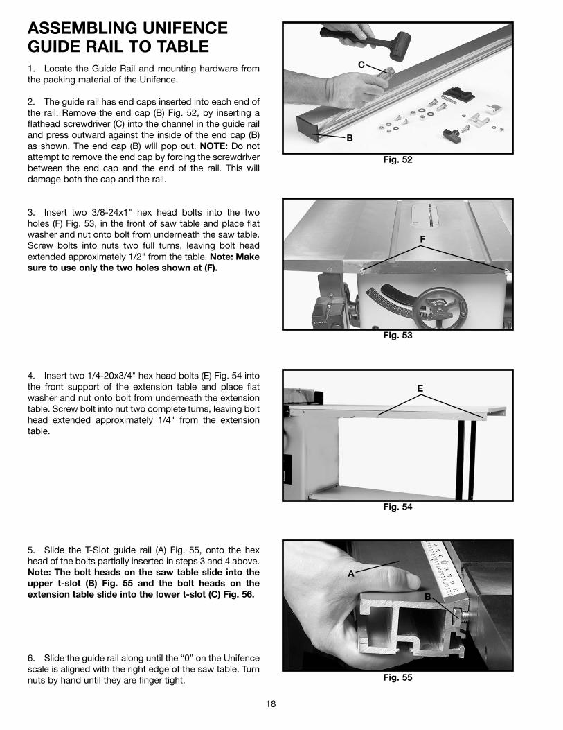
ASSEMBLING UNIFENCEGUIDE RAIL TO TABLE1. Locate the Guide Rail and mounting hardware fromthe packing material of the Unifence.
2. The guide rail has end caps inserted into each end ofthe rail. Remove the end cap (B) Fig. 52, by inserting aflathead screwdriver (C) into the channel in the guide railand press outward against the inside of the end cap (B)as shown. The end cap (B) will pop out. NOTE: Do notattempt to remove the end cap by forcing the screwdriverbetween the end cap and the end of the rail. This willdamage both the cap and the rail.
3. Insert two 3/8-24x1" hex head bolts into the twoholes (F) Fig. 53, in the front of saw table and place flatwasher and nut onto bolt from underneath the saw table.Screw bolts into nuts two full turns, leaving bolt headextended approximately 1/2" from the table. Note: Makesure to use only the two holes shown at (F).
4. Insert two 1/4-20x3/4" hex head bolts (E) Fig. 54 intothe front support of the extension table and place flatwasher and nut onto bolt from underneath the extensiontable. Screw bolt into nut two complete turns, leaving bolthead extended approximately 1/4" from the extensiontable.
5. Slide the T-SIot guide rail (A) Fig. 55, onto the hexhead of the bolts partially inserted in steps 3 and 4 above.Note: The bolt heads on the saw table slide into theupper t-slot (B) Fig. 55 and the bolt heads on theextension table slide into the lower t-slot (C) Fig. 56.
6. Slide the guide rail along until the “0” on the Unifencescale is aligned with the right edge of the saw table. Turnnuts by hand until they are finger tight.
Fig. 52
C
B
Fig. 53
Fig. 54
F
E
Fig. 55
A
B
19
Fig. 56
A
C
Fig. 58
C
K
H
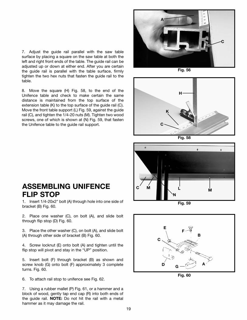
7. Adjust the guide rail parallel with the saw tablesurface by placing a square on the saw table at both theleft and right front ends of the table. The guide rail can beadjusted up or down at either end. After you are certainthe guide rail is parallel with the table surface, firmlytighten the two hex nuts that fasten the guide rail to thetable.
8. Move the square (H) Fig. 58, to the end of theUnifence table and check to make certain the samedistance is maintained from the top surface of theextension table (K) to the top surface of the guide rail (C).Move the front table support (L) Fig. 59, against the guiderail (C), and tighten the 1/4-20 nuts (M). Tighten two woodscrews, one of which is shown at (N) Fig. 59, that fastenthe Unifence table to the guide rail support.
Fig. 59
MMLC
N
ASSEMBLING UNIFENCEFLIP STOP1. Insert 1/4-20x2" bolt (A) through hole into one side ofbracket (B) Fig. 60.
2. Place one washer (C), on bolt (A), and slide boltthrough flip stop (D) Fig. 60.
3. Place the other washer (C), on bolt (A), and slide bolt(A) through other side of bracket (B) Fig. 60.
4. Screw locknut (E) onto bolt (A) and tighten until theflip stop will pivot and stay in the “UP” position.
5. Insert bolt (F) through bracket (B) as shown andscrew knob (G) onto bolt (F) approximately 3 completeturns. Fig. 60.
6. To attach rail stop to unifence see Fig. 62.
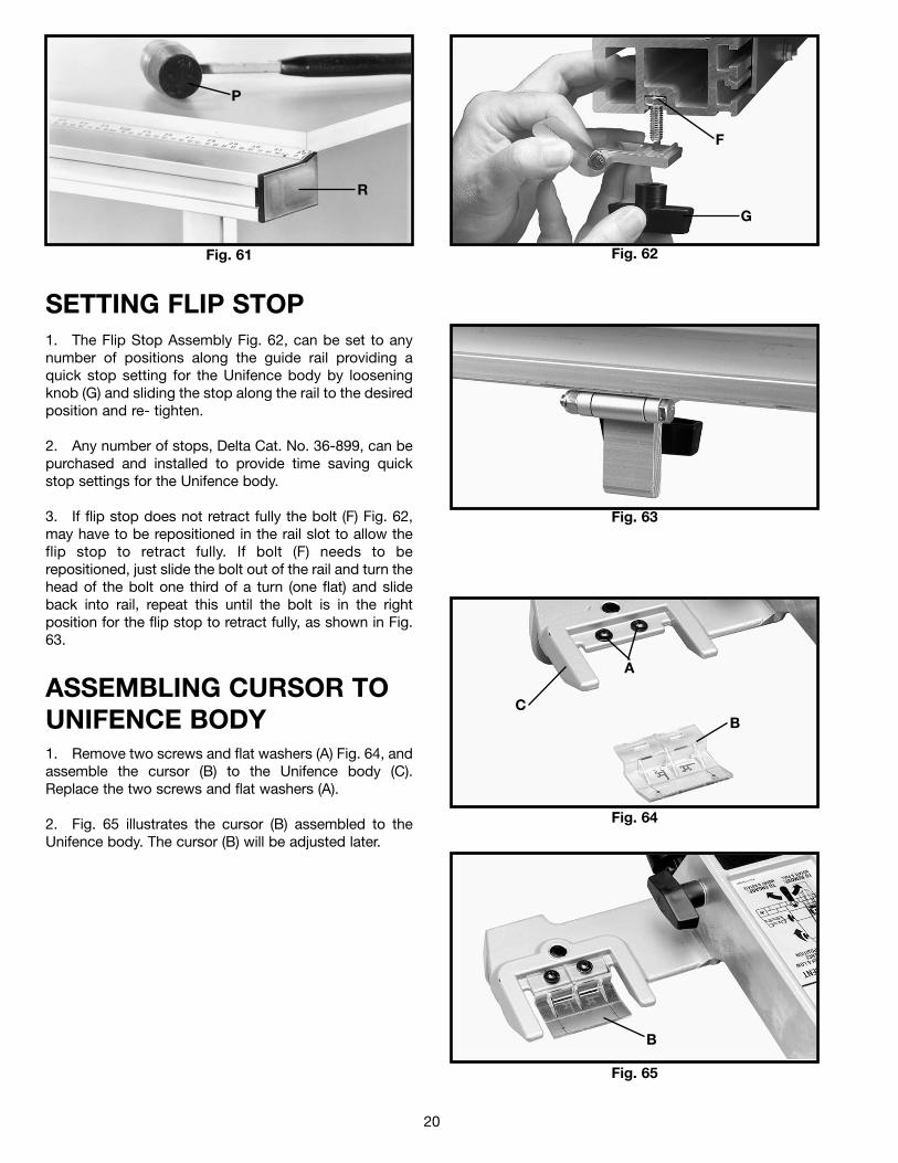
7. Using a rubber mallet (P) Fig. 61, or a hammer and ablock of wood, gently tap end cap (R) into both ends ofthe guide rail. NOTE: Do not hit the rail with a metalhammer as it may damage the rail.
Fig. 60
E
C
FB
AGD
20
Fig. 61 Fig. 62
P
R
F
G
Fig. 63
SETTING FLIP STOP1. The Flip Stop Assembly Fig. 62, can be set to anynumber of positions along the guide rail providing aquick stop setting for the Unifence body by looseningknob (G) and sliding the stop along the rail to the desiredposition and re- tighten.
2. Any number of stops, Delta Cat. No. 36-899, can bepurchased and installed to provide time saving quickstop settings for the Unifence body.
3. If flip stop does not retract fully the bolt (F) Fig. 62,may have to be repositioned in the rail slot to allow theflip stop to retract fully. If bolt (F) needs to berepositioned, just slide the bolt out of the rail and turn thehead of the bolt one third of a turn (one flat) and slideback into rail, repeat this until the bolt is in the rightposition for the flip stop to retract fully, as shown in Fig.63.
Fig. 64
Fig. 65
A
CB
B
ASSEMBLING CURSOR TOUNIFENCE BODY1. Remove two screws and flat washers (A) Fig. 64, andassemble the cursor (B) to the Unifence body (C).Replace the two screws and flat washers (A).
2. Fig. 65 illustrates the cursor (B) assembled to theUnifence body. The cursor (B) will be adjusted later.
21
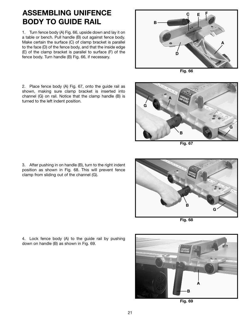
ASSEMBLING UNIFENCEBODY TO GUIDE RAIL1. Turn fence body (A) Fig. 66, upside down and lay it ona table or bench. Pull handle (B) out against fence body.Make certain the surface (C) of clamp bracket is parallelto the face (D) of the fence body, and that the inside edge(E) of the clamp bracket is parallel to surface (F) of thefence body. Turn handle (B) Fig. 66, if necessary.
2. Place fence body (A) Fig. 67, onto the guide rail asshown, making sure clamp bracket is inserted intochannel (G) on rail. Notice that the clamp handle (B) isturned to the left indent position.
3. After pushing in on handle (B), turn to the right indentposition as shown in Fig. 68. This will prevent fenceclamp from sliding out of the channel (G).
4. Lock fence body (A) to the guide rail by pushingdown on handle (B) as shown in Fig. 69.
Fig. 66
Fig. 67
B
C E F
D
A
B
G
G
Fig. 68
BG
Fig. 69
A
B
A
22
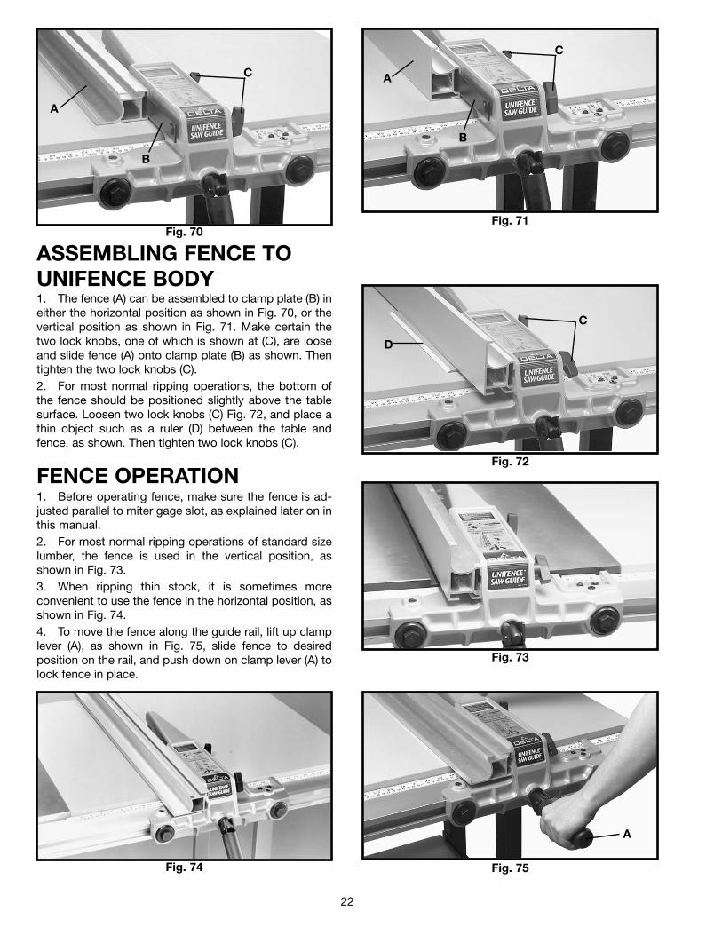
ASSEMBLING FENCE TOUNIFENCE BODY1. The fence (A) can be assembled to clamp plate (B) ineither the horizontal position as shown in Fig. 70, or thevertical position as shown in Fig. 71. Make certain thetwo lock knobs, one of which is shown at (C), are looseand slide fence (A) onto clamp plate (B) as shown. Thentighten the two lock knobs (C).2. For most normal ripping operations, the bottom ofthe fence should be positioned slightly above the tablesurface. Loosen two lock knobs (C) Fig. 72, and place athin object such as a ruler (D) between the table andfence, as shown. Then tighten two lock knobs (C).
Fig. 70Fig. 71
Fig. 72
Fig. 73
C
A
B
C
A
B
C
D
FENCE OPERATION1. Before operating fence, make sure the fence is ad-justed parallel to miter gage slot, as explained later on inthis manual.2. For most normal ripping operations of standard sizelumber, the fence is used in the vertical position, asshown in Fig. 73.3. When ripping thin stock, it is sometimes moreconvenient to use the fence in the horizontal position, asshown in Fig. 74.4. To move the fence along the guide rail, lift up clamplever (A), as shown in Fig. 75, slide fence to desiredposition on the rail, and push down on clamp lever (A) tolock fence in place.
Fig. 74 Fig. 75
A
23
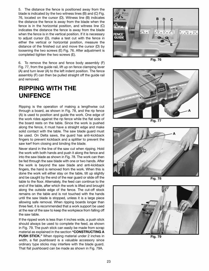
5. The distance the fence is positioned away from theblade is indicated by the two witness lines (B) and (C) Fig.76, located on the cursor (D). Witness line (B) indicatesthe distance the fence is away from the blade when thefence is in the horizontal position, and witness line (C)indicates the distance the fence is away from the bladewhen the fence is in the vertical position. If it is necessaryto adjust cursor (D), make a test cut with the fence ineither the vertical or horizontal position, measure thedistance of the finished cut and move the cursor (D) byloosening the two screws (E) Fig. 76. After adjustment iscompleted tighten the two screws (E).
6. To remove the fence and fence body assembly (F)Fig. 77, from the guide rail, lift up on fence clamping lever(A) and turn lever (A) to the left indent position. The fenceassembly (F) can then be pulled straight off the guide railand removed.
RIPPING WITH THEUNIFENCE
Ripping is the operation of making a lengthwise cutthrough a board, as shown in Fig. 78, and the rip fence(A) is used to position and guide the work. One edge ofthe work rides against the rip fence while the flat side ofthe board rests on the table. Since the work is pushedalong the fence, it must have a straight edge and makesolid contact with the table. The saw blade guard mustbe used. On Delta saws, the guard has anti-kickbackfingers to prevent kickback and a splitter to prevent thesaw kerf from closing and binding the blade.
Never stand in the line of the saw cut when ripping. Holdthe work with both hands and push it along the fence andinto the saw blade as shown in Fig. 78. The work can thenbe fed through the saw blade with one or two hands. Afterthe work is beyond the saw blade and anti-kickbackfingers, the hand is removed from the work. When this isdone the work will either stay on the table, tilt up slightlyand be caught by the end of the rear guard or slide off thetable to the floor. Alternately, the feed can continue to theend of the table, after which the work is lifted and broughtalong the outside edge of the fence. The cut-off stockremains on the table and is not touched with the handsuntil the saw blade is stopped, unless it is a large pieceallowing safe removal. When ripping boards longer thanthree feet, it is recommended that a work support be usedat the rear of the saw to keep the workpiece from falling offthe saw table.
If the ripped work is less than 4 inches wide, a push stickshould always be used to complete the feed, as shownin Fig. 79. The push stick can easily be made from scrapmaterial as explained in the section “CONSTRUCTING APUSH STICK.” When ripping material under 2 inches inwidth, a flat pushboard is a valuable accessory sinceordinary type sticks may interfere with the blade guard.That flat pushboard can be made as shown in Fig. 79A.
Fig. 76
Fig. 77
B D C
E
F
A
Fig. 78
Fig. 79
A
24
Fig. 80
Fig. 81
A
B
B
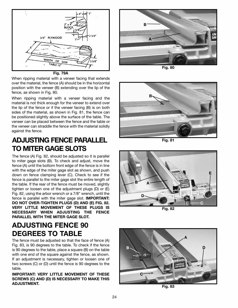
When ripping material with a veneer facing that extendsover the material, the fence (A) should be in the horizontalposition with the veneer (B) extending over the lip of thefence, as shown in Fig. 80.
When ripping material with a veneer facing and thematerial is not thick enough for the veneer to extend overthe lip of the fence or if the veneer facing (B) is on bothsides of the material, as shown in Fig. 81, the fence canbe positioned slightly above the surface of the table. Theveneer can be placed between the fence and the table orthe veneer can straddle the fence with the material solidlyagainst the fence.
ADJUSTING FENCE PARALLELTO MITER GAGE SLOTSThe fence (A) Fig. 82, should be adjusted so it is parallelto miter gage slots (B). To check and adjust, move thefence (A) until the bottom front edge of the fence is in linewith the edge of the miter gage slot as shown, and pushdown on fence clamping lever (C). Check to see if thefence is parallel to the miter gage slot the entire length ofthe table. If the rear of the fence must be moved, slightlytighten or loosen one of the adjustment plugs (D) or (E)Fig. 82, using the arbor wrench or a 7/8" wrench, until thefence is parallel with the miter gage slot. IMPORTANT:DO NOT OVER-TIGHTEN PLUGS (D) AND (E) FIG. 82.VERY LITTLE MOVEMENT OF THESE PLUGS ISNECESSARY WHEN ADJUSTING THE FENCEPARALLEL WITH THE MITER GAGE SLOT.
ADJUSTING FENCE 90DEGREES TO TABLEThe fence must be adjusted so that the face of fence (A)Fig. 83, is 90 degrees to the table. To check if the fenceis 90 degrees to the table, place a square (B) on the tablewith one end of the square against the fence, as shown.If an adjustment is necessary, tighten or loosen one oftwo screws (C) or (D) until the fence is 90 degrees to thetable.
IMPORTANT: VERY LITTLE MOVEMENT OF THESESCREWS (C) AND (D) IS NECESSARY TO MAKE THISADJUSTMENT.
Fig. 82
Fig. 83
AB
C
D
E
B
A
D
C
Fig. 79A
25
Fig. 84
Fig. 85
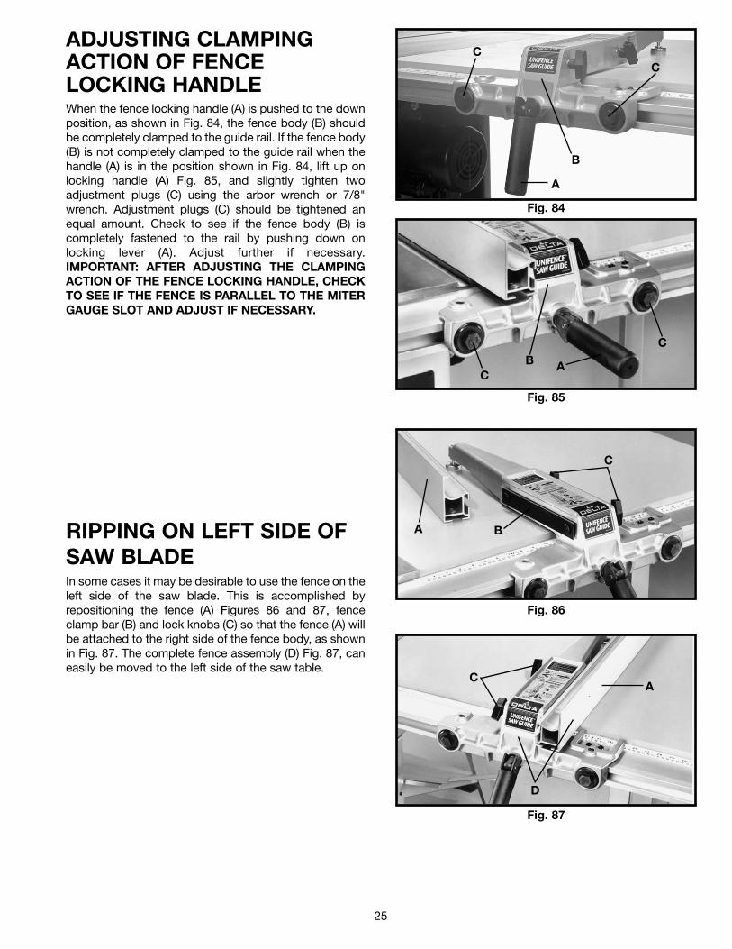
ADJUSTING CLAMPINGACTION OF FENCELOCKING HANDLEWhen the fence locking handle (A) is pushed to the downposition, as shown in Fig. 84, the fence body (B) shouldbe completely clamped to the guide rail. If the fence body(B) is not completely clamped to the guide rail when thehandle (A) is in the position shown in Fig. 84, lift up onlocking handle (A) Fig. 85, and slightly tighten twoadjustment plugs (C) using the arbor wrench or 7/8"wrench. Adjustment plugs (C) should be tightened anequal amount. Check to see if the fence body (B) iscompletely fastened to the rail by pushing down onlocking lever (A). Adjust further if necessary.IMPORTANT: AFTER ADJUSTING THE CLAMPINGACTION OF THE FENCE LOCKING HANDLE, CHECKTO SEE IF THE FENCE IS PARALLEL TO THE MITERGAUGE SLOT AND ADJUST IF NECESSARY.
B
A
CC
ABC
C
RIPPING ON LEFT SIDE OFSAW BLADEIn some cases it may be desirable to use the fence on theleft side of the saw blade. This is accomplished byrepositioning the fence (A) Figures 86 and 87, fenceclamp bar (B) and lock knobs (C) so that the fence (A) willbe attached to the right side of the fence body, as shownin Fig. 87. The complete fence assembly (D) Fig. 87, caneasily be moved to the left side of the saw table.
Fig. 86
Fig. 87
A B
C
CA
D
26
Fig. 88
Fig. 90
A
Fig. 89
B
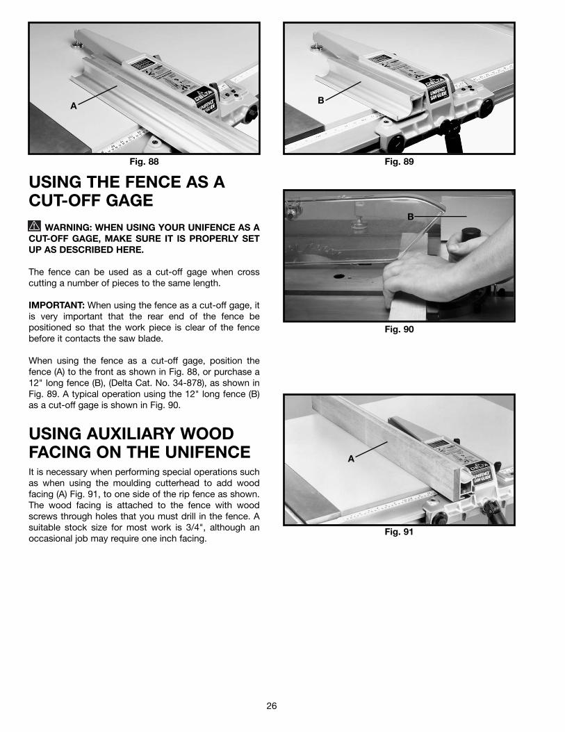
USING THE FENCE AS ACUT-OFF GAGE
WARNING: WHEN USING YOUR UNIFENCE AS ACUT-OFF GAGE, MAKE SURE IT IS PROPERLY SETUP AS DESCRIBED HERE.
The fence can be used as a cut-off gage when crosscutting a number of pieces to the same length.
IMPORTANT: When using the fence as a cut-off gage, itis very important that the rear end of the fence bepositioned so that the work piece is clear of the fencebefore it contacts the saw blade.
When using the fence as a cut-off gage, position thefence (A) to the front as shown in Fig. 88, or purchase a12" long fence (B), (Delta Cat. No. 34-878), as shown inFig. 89. A typical operation using the 12" long fence (B)as a cut-off gage is shown in Fig. 90.
USING AUXILIARY WOODFACING ON THE UNIFENCE
Fig. 91
It is necessary when performing special operations suchas when using the moulding cutterhead to add woodfacing (A) Fig. 91, to one side of the rip fence as shown.The wood facing is attached to the fence with woodscrews through holes that you must drill in the fence. Asuitable stock size for most work is 3/4", although anoccasional job may require one inch facing.
A
B
27
ASSEMBLY INSTRUCTIONS FOR MODELS 36-844 &36-845 50" COMMERCIAL BIESEMEYER FENCE
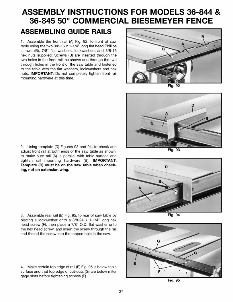
ASSEMBLING GUIDE RAILS1. Assemble the front rail (A) Fig. 92, to front of sawtable using the two 3/8-16 x 1-1/4" long flat head Phillipsscrews (B), 7/8" flat washers, lockwashers and 3/8-16hex nuts supplied. Screws (B) are inserted through thetwo holes in the front rail, as shown and through the twothrough holes in the front of the saw table and fastenedto the table with the flat washers, lockwashers and hexnuts. IMPORTANT: Do not completely tighten front railmounting hardware at this time.
2. Using template (D) Figures 93 and 94, to check andadjust front rail at both ends of the saw table as shown,to make sure rail (A) is parallel with table surface andtighten rail mounting hardware (B). IMPORTANT:Template (D) must be on the saw table when check-ing, not on extension wing.
3. Assemble rear rail (E) Fig. 95, to rear of saw table byplacing a lockwasher onto a 3/8-24 x 1-1/4" long hexhead screw (F), then place a 7/8" O.D. flat washer ontothe hex head screw, and insert the screw through the railand thread the screw into the tapped hole in the saw.
4. Make certain top edge of rail (E) Fig. 95 is below tablesurface and that top edge of cut-outs (G) are below mitergage slots before tightening screws (F).
Fig. 92
Fig. 93
Fig. 94
Fig. 95
AB
B
D
AB
D
A
B
E
G
G
F
28
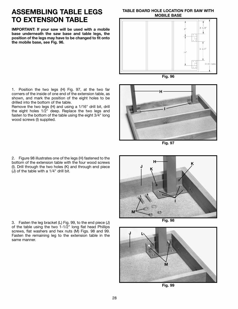
ASSEMBLING TABLE LEGS TO EXTENSION TABLEIMPORTANT: If your saw will be used with a mobilebase underneath the saw base and table legs, theposition of the legs may have to be changed to fit ontothe mobile base, see Fig. 96.
1. Position the two legs (H) Fig. 97, at the two farcorners of the inside of one end of the extension table, asshown, and mark the position of the eight holes to bedrilled into the bottom of the table. Remove the two legs (H) and using a 1/16" drill bit, drillthe eight holes 1/2" deep. Replace the two legs andfasten to the bottom of the table using the eight 3/4" longwood screws (I) supplied.
2. Figure 98 illustrates one of the legs (H) fastened to thebottom of the extension table with the four wood screws(I). Drill through the two holes (K) and through end piece(J) of the table with a 1/4" drill bit.
3. Fasten the leg bracket (L) Fig. 99, to the end piece (J)of the table using the two 1-1/2" long flat head Phillipsscrews, flat washers and hex nuts (M) Figs. 98 and 99.Fasten the remaining leg to the extension table in thesame manner.
Fig. 96
TABLE BOARD HOLE LOCATION FOR SAW WITHMOBILE BASE
Fig. 97
Fig. 98
Fig. 99
H
I
H
I
J
M
L
M
J
KK
29
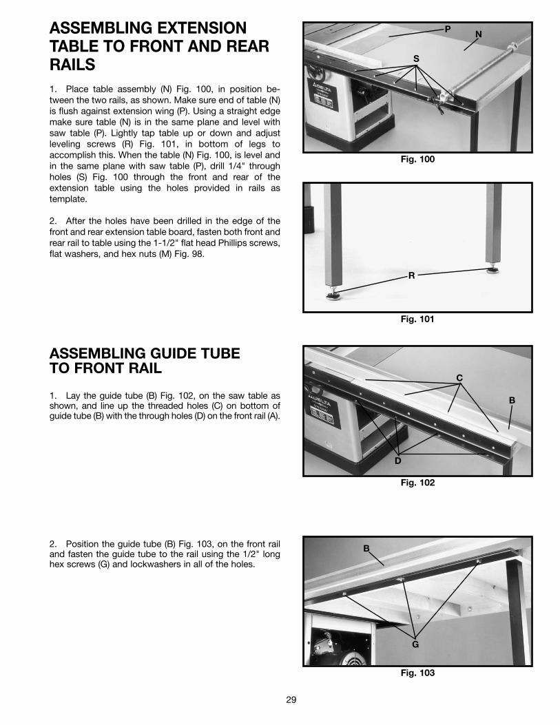
ASSEMBLING EXTENSIONTABLE TO FRONT AND REARRAILS1. Place table assembly (N) Fig. 100, in position be-tween the two rails, as shown. Make sure end of table (N)is flush against extension wing (P). Using a straight edgemake sure table (N) is in the same plane and level withsaw table (P). Lightly tap table up or down and adjustleveling screws (R) Fig. 101, in bottom of legs toaccomplish this. When the table (N) Fig. 100, is level andin the same plane with saw table (P), drill 1/4" throughholes (S) Fig. 100 through the front and rear of theextension table using the holes provided in rails astemplate.
2. After the holes have been drilled in the edge of thefront and rear extension table board, fasten both front andrear rail to table using the 1-1/2" flat head Phillips screws,flat washers, and hex nuts (M) Fig. 98.
Fig. 100
Fig. 101
P N
S
R
Fig. 102
Fig. 103
ASSEMBLING GUIDE TUBE TO FRONT RAIL
1. Lay the guide tube (B) Fig. 102, on the saw table asshown, and line up the threaded holes (C) on bottom ofguide tube (B) with the through holes (D) on the front rail (A).
2. Position the guide tube (B) Fig. 103, on the front railand fasten the guide tube to the rail using the 1/2" longhex screws (G) and lockwashers in all of the holes.
C
B
D
B
G
30
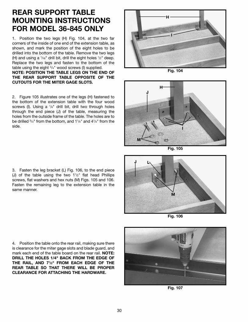
REAR SUPPORT TABLEMOUNTING INSTRUCTIONSFOR MODEL 36-845 ONLY1. Position the two legs (H) Fig. 104, at the two farcorners of the inside of one end of the extension table, asshown, and mark the position of the eight holes to bedrilled into the bottom of the table. Remove the two legs(H) and using a 1/16" drill bit, drill the eight holes 1/2" deep.Replace the two legs and fasten to the bottom of thetable using the eight 3/4" wood screws (I) supplied.NOTE: POSITION THE TABLE LEGS ON THE END OFTHE REAR SUPPORT TABLE OPPOSITE OF THECUTOUTS FOR THE MITER GAGE SLOTS.
2. Figure 105 illustrates one of the legs (H) fastened tothe bottom of the extension table with the four woodscrews (I). Using a 1/4" drill bit, drill two through holesthrough the end piece (J) of the table, measuring theholes from the outside frame of the table. The holes are tobe drilled 3/4" from the bottom, and 11/4" and 41/4" from theside.
3. Fasten the leg bracket (L) Fig. 106, to the end piece(J) of the table using the two 11/2" flat head Phillipsscrews, flat washers and hex nuts (M) Figs. 105 and 106.Fasten the remaining leg to the extension table in thesame manner.
4. Position the table onto the rear rail, making sure thereis clearance for the miter gage slots and blade guard, andmark each end of the table board on the rear rail. NOTE:DRILL THE HOLES 1/4" BACK FROM THE EDGE OFTHE RAIL, AND 71/2" FROM EACH EDGE OF THEREAR TABLE SO THAT THERE WILL BE PROPERCLEARANCE FOR ATTACHING THE HARDWARE.
Fig. 104
H
I
Fig. 105
Fig. 106
H
I
J
M
L
M
J
Fig. 107
31
Fig. 108
Fig. 109
Fig. 110
Fig. 111
R
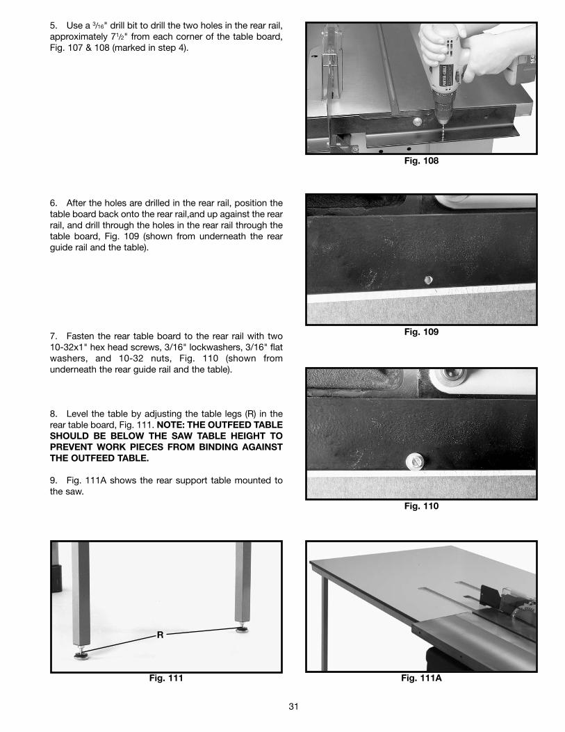
5. Use a 3/16" drill bit to drill the two holes in the rear rail,approximately 71/2" from each corner of the table board,Fig. 107 & 108 (marked in step 4).
6. After the holes are drilled in the rear rail, position thetable board back onto the rear rail,and up against the rearrail, and drill through the holes in the rear rail through thetable board, Fig. 109 (shown from underneath the rearguide rail and the table).
7. Fasten the rear table board to the rear rail with two10-32x1" hex head screws, 3/16" lockwashers, 3/16" flatwashers, and 10-32 nuts, Fig. 110 (shown fromunderneath the rear guide rail and the table).
8. Level the table by adjusting the table legs (R) in therear table board, Fig. 111. NOTE: THE OUTFEED TABLESHOULD BE BELOW THE SAW TABLE HEIGHT TOPREVENT WORK PIECES FROM BINDING AGAINSTTHE OUTFEED TABLE.
9. Fig. 111A shows the rear support table mounted tothe saw.
Fig. 111A
32
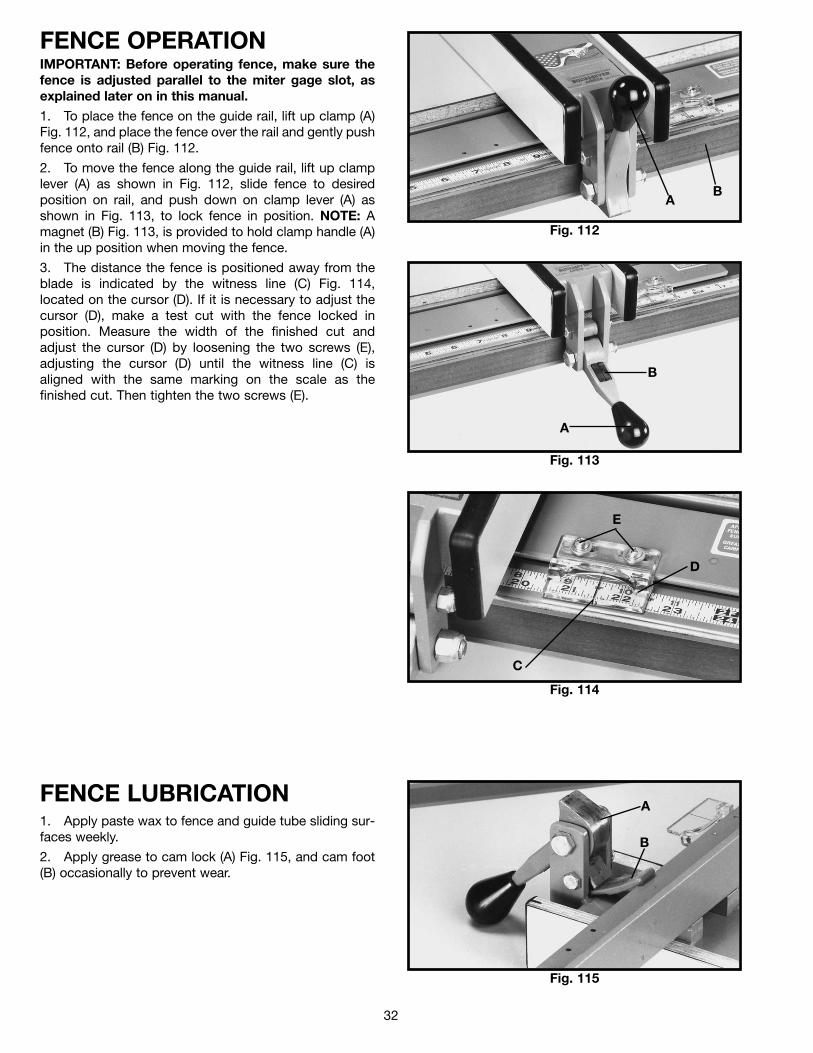
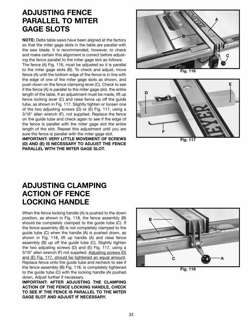
FENCE OPERATIONIMPORTANT: Before operating fence, make sure thefence is adjusted parallel to the miter gage slot, asexplained later on in this manual.
1. To place the fence on the guide rail, lift up clamp (A)Fig. 112, and place the fence over the rail and gently pushfence onto rail (B) Fig. 112.
2. To move the fence along the guide rail, lift up clamplever (A) as shown in Fig. 112, slide fence to desiredposition on rail, and push down on clamp lever (A) asshown in Fig. 113, to lock fence in position. NOTE: Amagnet (B) Fig. 113, is provided to hold clamp handle (A)in the up position when moving the fence.
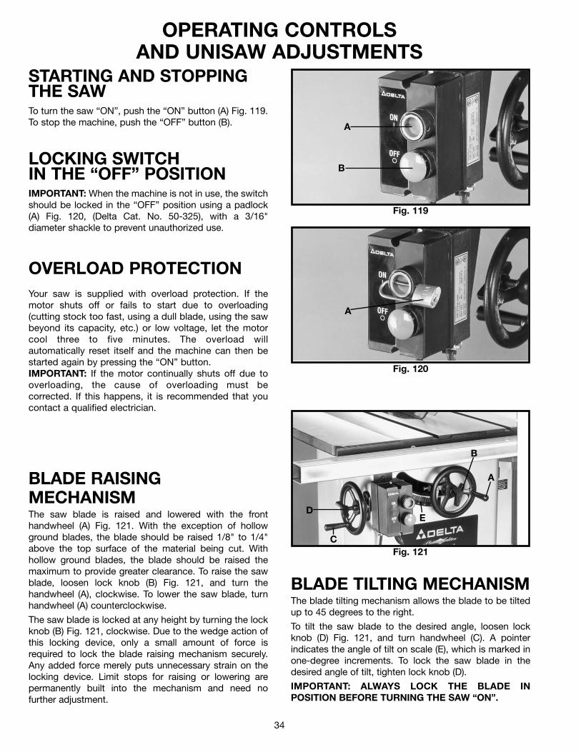
3. The distance the fence is positioned away from theblade is indicated by the witness line (C) Fig. 114,located on the cursor (D). If it is necessary to adjust thecursor (D), make a test cut with the fence locked inposition. Measure the width of the finished cut andadjust the cursor (D) by loosening the two screws (E),adjusting the cursor (D) until the witness line (C) isaligned with the same marking on the scale as thefinished cut. Then tighten the two screws (E).
Fig. 112
Fig. 113
Fig. 114
AB
B
A
C
D
E
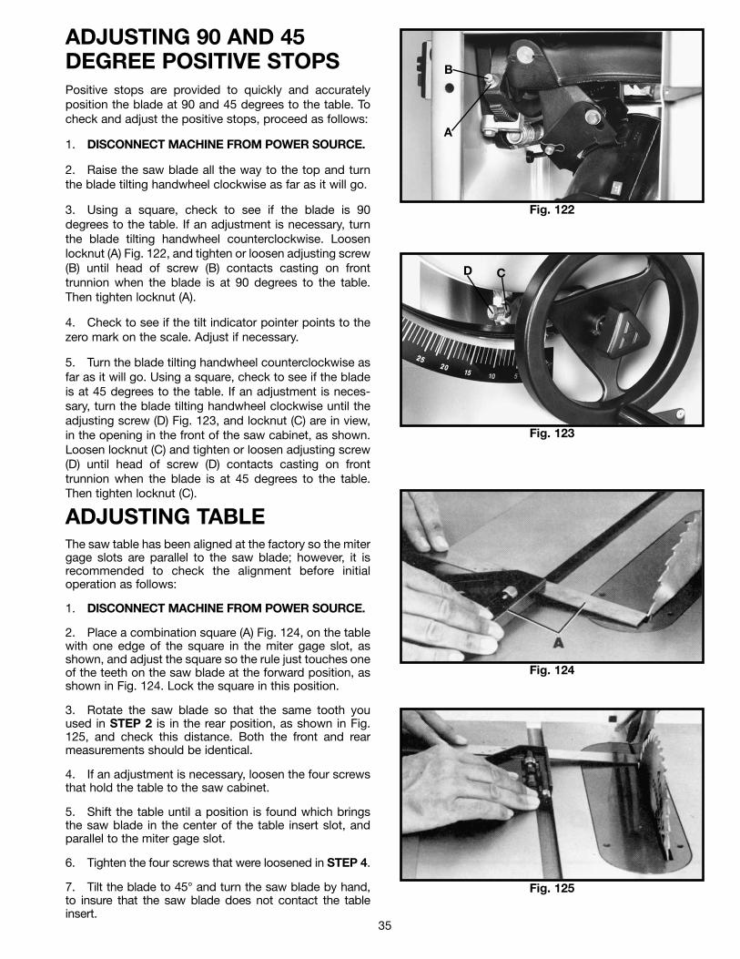
FENCE LUBRICATION1. Apply paste wax to fence and guide tube sliding sur-faces weekly.
2. Apply grease to cam lock (A) Fig. 115, and cam foot(B) occasionally to prevent wear.
Fig. 115
A
B
33
ADJUSTING FENCEPARALLEL TO MITER GAGE SLOTSNOTE: Delta table saws have been aligned at the factoryso that the miter gage slots in the table are parallel withthe saw blade. It is recommended, however, to checkand make certain this alignment is correct before adjust-ing the fence parallel to the miter gage slot as follows:The fence (A) Fig. 116, must be adjusted so it is parallelto the miter gage slots (B). To check and adjust, movefence (A) until the bottom edge of the fence is in line withthe edge of one of the miter gage slots as shown, andpush down on the fence clamping lever (C). Check to seeif the fence (A) is parallel to the miter gage slot, the entirelength of the table. If an adjustment must be made, lift upfence locking lever (C) and raise fence up off the guidetube, as shown in Fig. 117. Slightly tighten or loosen oneof the two adjusting screws (D) or (E) Fig. 117, using a3/16" alIen wrench (F), not supplied. Replace the fenceon the guide tube and check again to see if the edge ofthe fence is parallel with the miter gage slot the entirelength of the slot. Repeat this adjustment until you aresure the fence is parallel with the miter gage slot.IMPORTANT: VERY LITTLE MOVEMENT OF SCREWS(D) AND (E) IS NECESSARY TO ADJUST THE FENCEPARALLEL WITH THE MITER GAGE SLOT.
ADJUSTING CLAMPINGACTION OF FENCELOCKING HANDLEWhen the fence locking handle (A) is pushed to the downposition, as shown in Fig. 118, the fence assembly (B)should be completely clamped to the guide tube (C). Ifthe fence assembly (B) is not completely clamped to theguide tube (C) when the handle (A) is pushed down, asshown in Fig. 118, lift up handle (A) and raise fenceassembly (B) up off the guide tube (C). Slightly tightenthe two adjusting screws (D) and (E) Fig. 117, using a3/16" allen wrench (F) not supplied. Adjusting screws (D)and (E) Fig. 117. should be tightened an equal amount.Replace fence onto the guide tube and recheck to see ifthe fence assembly (B) Fig. 118, is completely tightenedto the guide tube (C) with the locking handle (A) pusheddown. Adjust further if necessary.IMPORTANT: AFTER ADJUSTING THE CLAMPINGACTION OF THE FENCE LOCKING HANDLE, CHECKTO SEE IF THE FENCE IS PARALLEL TO THE MITERGAGE SLOT AND ADJUST IF NECESSARY.
Fig. 116
Fig. 117
Fig. 118
A
B
D
E
F
A
B
C
C
34
OPERATING CONTROLS AND UNISAW ADJUSTMENTS
STARTING AND STOPPING THE SAWTo turn the saw “ON”, push the “ON” button (A) Fig. 119.To stop the machine, push the “OFF” button (B).
Fig. 119
A
BLOCKING SWITCH IN THE “OFF” POSITIONIMPORTANT: When the machine is not in use, the switchshould be locked in the “OFF” position using a padlock(A) Fig. 120, (Delta Cat. No. 50-325), with a 3/16"diameter shackle to prevent unauthorized use.
Fig. 120
A
BLADE RAISINGMECHANISMThe saw blade is raised and lowered with the fronthandwheel (A) Fig. 121. With the exception of hollowground blades, the blade should be raised 1/8" to 1/4"above the top surface of the material being cut. Withhollow ground blades, the blade should be raised themaximum to provide greater clearance. To raise the sawblade, loosen lock knob (B) Fig. 121, and turn thehandwheel (A), clockwise. To lower the saw blade, turnhandwheel (A) counterclockwise.
The saw blade is locked at any height by turning the lockknob (B) Fig. 121, clockwise. Due to the wedge action ofthis locking device, only a small amount of force isrequired to lock the blade raising mechanism securely.Any added force merely puts unnecessary strain on thelocking device. Limit stops for raising or lowering arepermanently built into the mechanism and need nofurther adjustment.
Fig. 121
D
C
B
A
E
BLADE TILTING MECHANISMThe blade tilting mechanism allows the blade to be tiltedup to 45 degrees to the right.
To tilt the saw blade to the desired angle, loosen lockknob (D) Fig. 121, and turn handwheel (C). A pointerindicates the angle of tilt on scale (E), which is marked inone-degree increments. To lock the saw blade in thedesired angle of tilt, tighten lock knob (D).
IMPORTANT: ALWAYS LOCK THE BLADE INPOSITION BEFORE TURNING THE SAW “ON”.
OVERLOAD PROTECTIONYour saw is supplied with overload protection. If themotor shuts off or fails to start due to overloading(cutting stock too fast, using a dull blade, using the sawbeyond its capacity, etc.) or low voltage, let the motorcool three to five minutes. The overload willautomatically reset itself and the machine can then bestarted again by pressing the “ON” button. IMPORTANT: If the motor continually shuts off due tooverloading, the cause of overloading must becorrected. If this happens, it is recommended that youcontact a qualified electrician.
35
ADJUSTING 90 AND 45DEGREE POSITIVE STOPSPositive stops are provided to quickly and accuratelyposition the blade at 90 and 45 degrees to the table. Tocheck and adjust the positive stops, proceed as follows:
1. DISCONNECT MACHINE FROM POWER SOURCE.
2. Raise the saw blade all the way to the top and turnthe blade tilting handwheel clockwise as far as it will go.
3. Using a square, check to see if the blade is 90degrees to the table. If an adjustment is necessary, turnthe blade tilting handwheel counterclockwise. Loosenlocknut (A) Fig. 122, and tighten or loosen adjusting screw(B) until head of screw (B) contacts casting on fronttrunnion when the blade is at 90 degrees to the table.Then tighten locknut (A).
4. Check to see if the tilt indicator pointer points to thezero mark on the scale. Adjust if necessary.
5. Turn the blade tilting handwheel counterclockwise asfar as it will go. Using a square, check to see if the bladeis at 45 degrees to the table. If an adjustment is neces-sary, turn the blade tilting handwheel clockwise until theadjusting screw (D) Fig. 123, and locknut (C) are in view,in the opening in the front of the saw cabinet, as shown.Loosen locknut (C) and tighten or loosen adjusting screw(D) until head of screw (D) contacts casting on fronttrunnion when the blade is at 45 degrees to the table.Then tighten locknut (C).
Fig. 122
Fig. 123
A
B
D C
ADJUSTING TABLEThe saw table has been aligned at the factory so the mitergage slots are parallel to the saw blade; however, it isrecommended to check the alignment before initialoperation as follows:
1. DISCONNECT MACHINE FROM POWER SOURCE.
2. Place a combination square (A) Fig. 124, on the tablewith one edge of the square in the miter gage slot, asshown, and adjust the square so the rule just touches oneof the teeth on the saw blade at the forward position, asshown in Fig. 124. Lock the square in this position.
3. Rotate the saw blade so that the same tooth youused in STEP 2 is in the rear position, as shown in Fig.125, and check this distance. Both the front and rearmeasurements should be identical.
4. If an adjustment is necessary, loosen the four screwsthat hold the table to the saw cabinet.
5. Shift the table until a position is found which bringsthe saw blade in the center of the table insert slot, andparallel to the miter gage slot.
6. Tighten the four screws that were loosened in STEP 4.
7. Tilt the blade to 45° and turn the saw blade by hand,to insure that the saw blade does not contact the tableinsert.
Fig. 124
Fig. 125
36
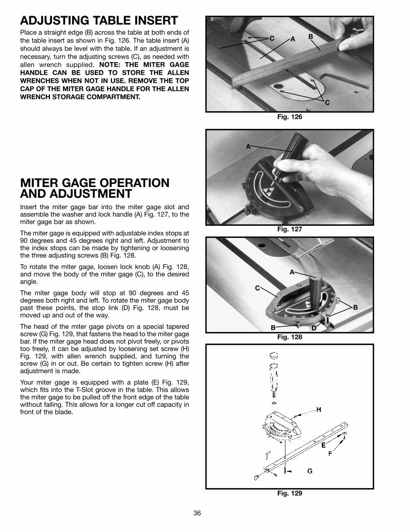
ADJUSTING TABLE INSERTPlace a straight edge (B) across the table at both ends ofthe table insert as shown in Fig. 126. The table insert (A)should always be level with the table. If an adjustment isnecessary, turn the adjusting screws (C), as needed withallen wrench supplied. NOTE: THE MITER GAGEHANDLE CAN BE USED TO STORE THE ALLENWRENCHES WHEN NOT IN USE. REMOVE THE TOPCAP OF THE MITER GAGE HANDLE FOR THE ALLENWRENCH STORAGE COMPARTMENT.
Fig. 126
BAC
C
MITER GAGE OPERATION AND ADJUSTMENTInsert the miter gage bar into the miter gage slot andassemble the washer and lock handle (A) Fig. 127, to themiter gage bar as shown.
The miter gage is equipped with adjustable index stops at90 degrees and 45 degrees right and left. Adjustment tothe index stops can be made by tightening or looseningthe three adjusting screws (B) Fig. 128.
To rotate the miter gage, loosen lock knob (A) Fig. 128,and move the body of the miter gage (C), to the desiredangle.
The miter gage body will stop at 90 degrees and 45degrees both right and left. To rotate the miter gage bodypast these points, the stop link (D) Fig. 128, must bemoved up and out of the way.
The head of the miter gage pivots on a special taperedscrew (G) Fig. 129, that fastens the head to the miter gagebar. If the miter gage head does not pivot freely, or pivotstoo freely, it can be adjusted by loosening set screw (H)Fig. 129, with allen wrench supplied, and turning thescrew (G) in or out. Be certain to tighten screw (H) afteradjustment is made.
Your miter gage is equipped with a plate (E) Fig. 129,which fits into the T-Slot groove in the table. This allowsthe miter gage to be pulled off the front edge of the tablewithout falling. This allows for a longer cut off capacity infront of the blade.
Fig. 127
Fig. 128
Fig. 129
A
A
C
B
B
D
37
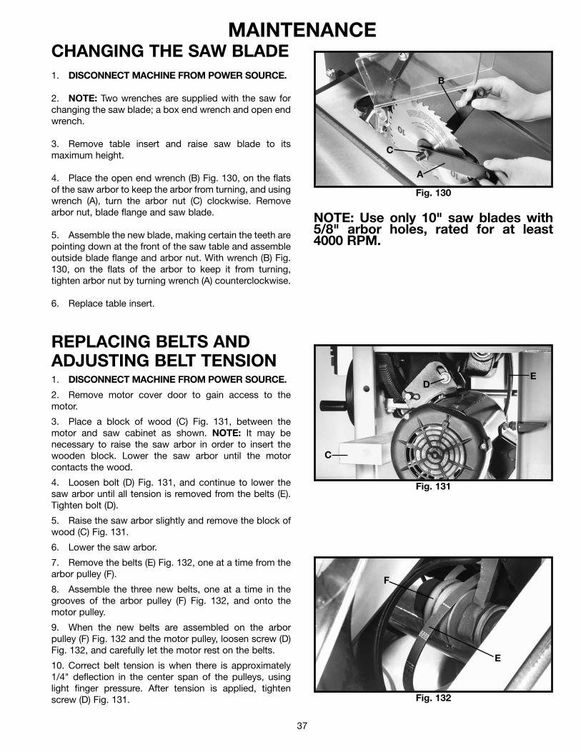
MAINTENANCECHANGING THE SAW BLADE1. DISCONNECT MACHINE FROM POWER SOURCE.
2. NOTE: Two wrenches are supplied with the saw forchanging the saw blade; a box end wrench and open endwrench.
3. Remove table insert and raise saw blade to itsmaximum height.
4. Place the open end wrench (B) Fig. 130, on the flatsof the saw arbor to keep the arbor from turning, and usingwrench (A), turn the arbor nut (C) clockwise. Removearbor nut, blade flange and saw blade.
5. Assemble the new blade, making certain the teeth arepointing down at the front of the saw table and assembleoutside blade flange and arbor nut. With wrench (B) Fig.130, on the flats of the arbor to keep it from turning,tighten arbor nut by turning wrench (A) counterclockwise.
6. Replace table insert.
Fig. 130
B
C
A
REPLACING BELTS ANDADJUSTING BELT TENSION1. DISCONNECT MACHINE FROM POWER SOURCE.
2. Remove motor cover door to gain access to themotor.
3. Place a block of wood (C) Fig. 131, between themotor and saw cabinet as shown. NOTE: It may benecessary to raise the saw arbor in order to insert thewooden block. Lower the saw arbor until the motorcontacts the wood.
4. Loosen bolt (D) Fig. 131, and continue to lower thesaw arbor until all tension is removed from the belts (E).Tighten bolt (D).
5. Raise the saw arbor slightly and remove the block ofwood (C) Fig. 131.
6. Lower the saw arbor.
7. Remove the belts (E) Fig. 132, one at a time from thearbor pulley (F).
8. Assemble the three new belts, one at a time in thegrooves of the arbor pulley (F) Fig. 132, and onto themotor pulley.
9. When the new belts are assembled on the arborpulley (F) Fig. 132 and the motor pulley, loosen screw (D)Fig. 132, and carefully let the motor rest on the belts.
10. Correct belt tension is when there is approximately1/4" deflection in the center span of the pulleys, usinglight finger pressure. After tension is applied, tightenscrew (D) Fig. 131.
Fig. 131
Fig. 132
C
ED
F
E
NOTE: Use only 10" saw blades with5/8" arbor holes, rated for at least4000 RPM.
38
PROTECTING CAST IRON TABLE FROM RUSTTo clean and protect cast iron tables from rust, you will need the following materials: 1 pushblock from a jointer, 1 sheetof medium Scotch-Brite™ Blending Hand Pad, 1 can of WD-40®, 1 can of degreaser, 1 can of TopCote® Aerosol. Applythe WD-40 and polish the table surface with the Scotch-Brite pad using the pushblock as a holddown. Degrease thetable, then apply the TopCote® accordingly.
OPERATIONSCommon sawing operations include ripping and crosscutting plus a few other standard operations of a fundamentalnature. As with all power machines, there is a certain amount of hazard involved with the operation and use of themachine. Using the machine with the respect and caution demanded as far as safety precautions are concerned, willconsiderably lessen the possibility of personal injury. However, if normal safety precautions are overlooked or completelyignored, personal injury to the operator can result. The following information describes the safe and proper method forperforming the most common sawing operations.
NOTE: THE USE OF ATTACHMENTS AND ACCESSORIES NOT RECOMMENDED BY DELTA MAY RESULT IN THERISK OF INJURY TO PERSONS.
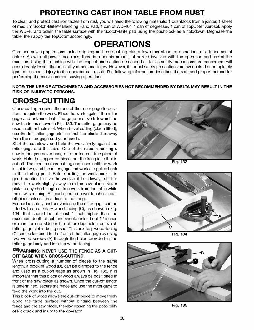
CROSS-CUTTINGCross-cutting requires the use of the miter gage to posi-tion and guide the work. Place the work against the mitergage and advance both the gage and work toward thesaw blade, as shown in Fig. 133. The miter gage may beused in either table slot. When bevel cutting (blade tilted),use the left miter gage slot so that the blade tilts awayfrom the miter gage and your hands.Start the cut slowly and hold the work firmly against themiter gage and the table. One of the rules in running asaw is that you never hang onto or touch a free piece ofwork. Hold the supported piece, not the free piece that iscut off. The feed in cross-cutting continues until the workis cut in two, and the miter gage and work are pulled backto the starting point. Before pulling the work back, it isgood practice to give the work a little sideways shift tomove the work slightly away from the saw blade. Neverpick up any short length of free work from the table whilethe saw is running. A smart operator never touches a cut-off piece unless it is at least a foot long.For added safety and convenience the miter gage can befitted with an auxiliary wood-facing (C), as shown in Fig.134, that should be at least 1 inch higher than themaximum depth of cut, and should extend out 12 inchesor more to one side or the other depending on whichmiter gage slot is being used. This auxiliary wood-facing(C) can be fastened to the front of the miter gage by usingtwo wood screws (A) through the holes provided in themiter gage body and into the wood-facing.
WARNING: NEVER USE THE FENCE AS A CUT-OFF GAGE WHEN CROSS-CUTTING.When cross-cutting a number of pieces to the samelength, a block of wood (B), can be clamped to the fenceand used as a cut-off gage as shown in Fig. 135. It isimportant that this block of wood always be positioned infront of the saw blade as shown. Once the cut-off lengthis determined, secure the fence and use the miter gage tofeed the work into the cut.This block of wood allows the cut-off piece to move freelyalong the table surface without binding between thefence and the saw blade, thereby lessening the possibilityof kickback and injury to the operator.
Fig. 133
Fig. 134
Fig. 135
C
A
B
39
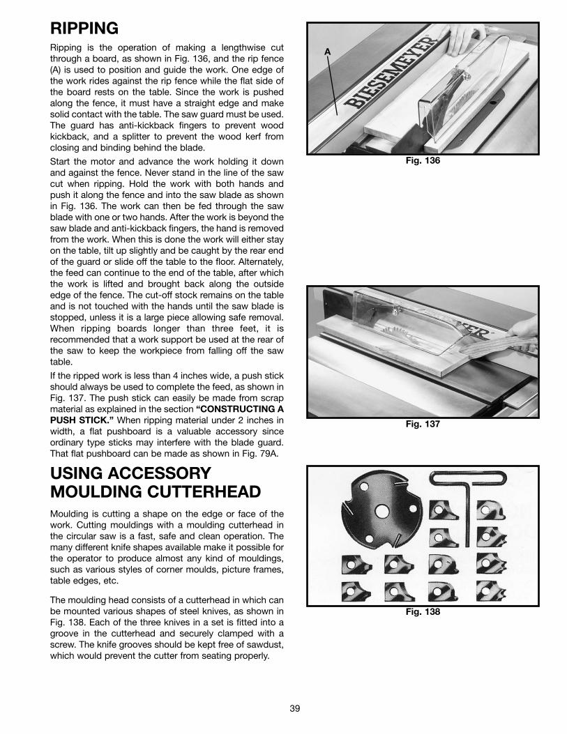
RIPPINGRipping is the operation of making a lengthwise cutthrough a board, as shown in Fig. 136, and the rip fence(A) is used to position and guide the work. One edge ofthe work rides against the rip fence while the flat side ofthe board rests on the table. Since the work is pushedalong the fence, it must have a straight edge and makesolid contact with the table. The saw guard must be used.The guard has anti-kickback fingers to prevent woodkickback, and a splitter to prevent the wood kerf fromclosing and binding behind the blade.
Start the motor and advance the work holding it downand against the fence. Never stand in the line of the sawcut when ripping. Hold the work with both hands andpush it along the fence and into the saw blade as shownin Fig. 136. The work can then be fed through the sawblade with one or two hands. After the work is beyond thesaw blade and anti-kickback fingers, the hand is removedfrom the work. When this is done the work will either stayon the table, tilt up slightly and be caught by the rear endof the guard or slide off the table to the floor. Alternately,the feed can continue to the end of the table, after whichthe work is lifted and brought back along the outsideedge of the fence. The cut-off stock remains on the tableand is not touched with the hands until the saw blade isstopped, unless it is a large piece allowing safe removal.When ripping boards longer than three feet, it isrecommended that a work support be used at the rear ofthe saw to keep the workpiece from falling off the sawtable.
If the ripped work is less than 4 inches wide, a push stickshould always be used to complete the feed, as shown inFig. 137. The push stick can easily be made from scrapmaterial as explained in the section “CONSTRUCTING APUSH STICK.” When ripping material under 2 inches inwidth, a flat pushboard is a valuable accessory sinceordinary type sticks may interfere with the blade guard.That flat pushboard can be made as shown in Fig. 79A.
Fig. 136
Fig. 137
A
USING ACCESSORYMOULDING CUTTERHEADMoulding is cutting a shape on the edge or face of thework. Cutting mouldings with a moulding cutterhead inthe circular saw is a fast, safe and clean operation. Themany different knife shapes available make it possible forthe operator to produce almost any kind of mouldings,such as various styles of corner moulds, picture frames,table edges, etc.
The moulding head consists of a cutterhead in which canbe mounted various shapes of steel knives, as shown inFig. 138. Each of the three knives in a set is fitted into agroove in the cutterhead and securely clamped with ascrew. The knife grooves should be kept free of sawdust,which would prevent the cutter from seating properly.
Fig. 138
40
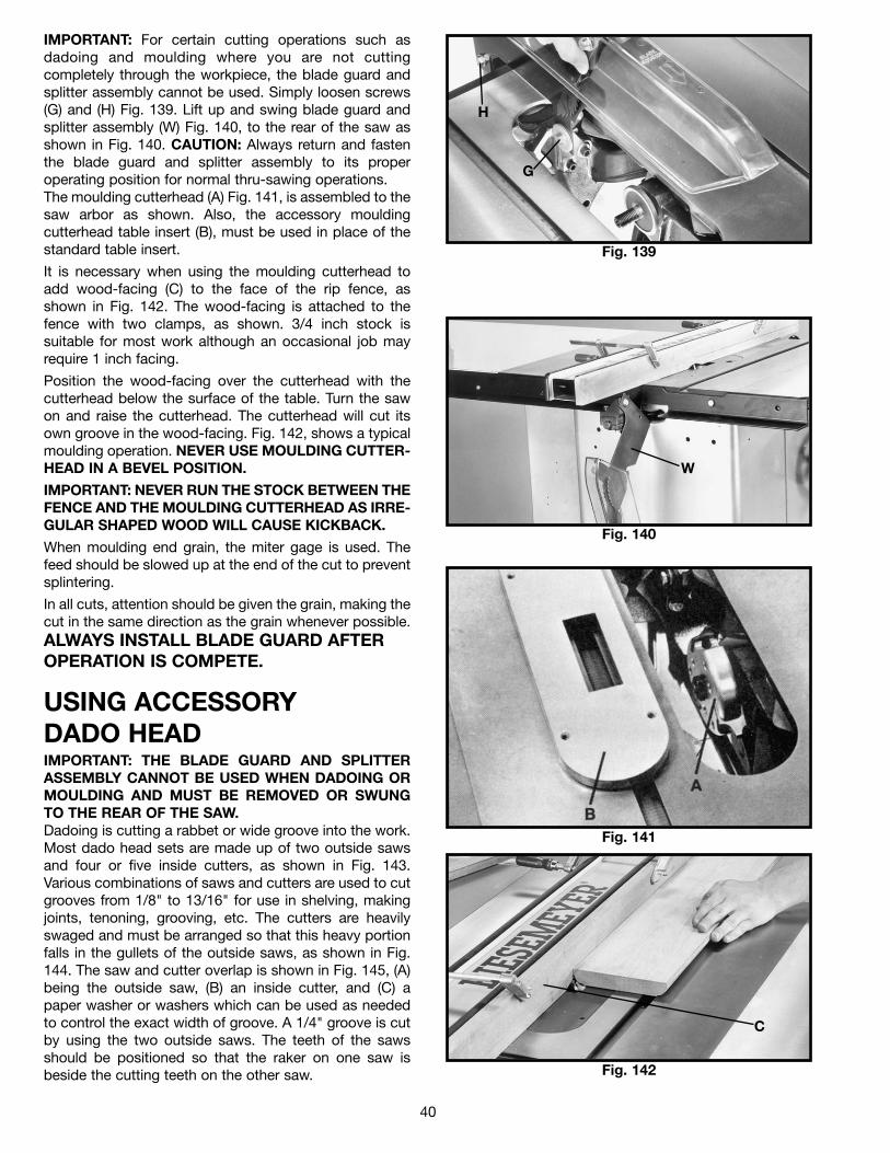
IMPORTANT: For certain cutting operations such asdadoing and moulding where you are not cuttingcompletely through the workpiece, the blade guard andsplitter assembly cannot be used. Simply loosen screws(G) and (H) Fig. 139. Lift up and swing blade guard andsplitter assembly (W) Fig. 140, to the rear of the saw asshown in Fig. 140. CAUTION: Always return and fastenthe blade guard and splitter assembly to its properoperating position for normal thru-sawing operations.The moulding cutterhead (A) Fig. 141, is assembled to thesaw arbor as shown. Also, the accessory mouldingcutterhead table insert (B), must be used in place of thestandard table insert.
It is necessary when using the moulding cutterhead toadd wood-facing (C) to the face of the rip fence, asshown in Fig. 142. The wood-facing is attached to thefence with two clamps, as shown. 3/4 inch stock issuitable for most work although an occasional job mayrequire 1 inch facing.
Position the wood-facing over the cutterhead with thecutterhead below the surface of the table. Turn the sawon and raise the cutterhead. The cutterhead will cut itsown groove in the wood-facing. Fig. 142, shows a typicalmoulding operation. NEVER USE MOULDING CUTTER-HEAD IN A BEVEL POSITION.
IMPORTANT: NEVER RUN THE STOCK BETWEEN THEFENCE AND THE MOULDING CUTTERHEAD AS IRRE-GULAR SHAPED WOOD WILL CAUSE KICKBACK.
When moulding end grain, the miter gage is used. Thefeed should be slowed up at the end of the cut to preventsplintering.
In all cuts, attention should be given the grain, making thecut in the same direction as the grain whenever possible.ALWAYS INSTALL BLADE GUARD AFTEROPERATION IS COMPETE.
Fig. 139
Fig. 140
Fig. 141
Fig. 142
G
H
W
C
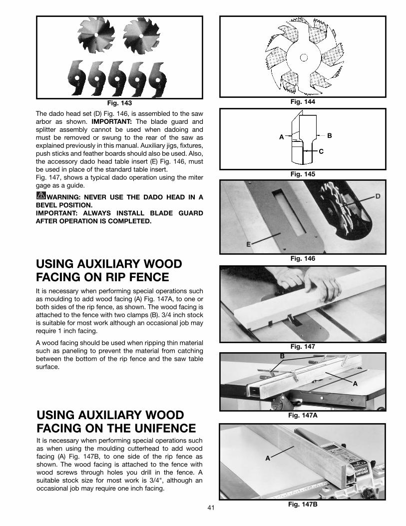
USING ACCESSORY DADO HEADIMPORTANT: THE BLADE GUARD AND SPLITTERASSEMBLY CANNOT BE USED WHEN DADOING ORMOULDING AND MUST BE REMOVED OR SWUNGTO THE REAR OF THE SAW.Dadoing is cutting a rabbet or wide groove into the work.Most dado head sets are made up of two outside sawsand four or five inside cutters, as shown in Fig. 143.Various combinations of saws and cutters are used to cutgrooves from 1/8" to 13/16" for use in shelving, makingjoints, tenoning, grooving, etc. The cutters are heavilyswaged and must be arranged so that this heavy portionfalls in the gullets of the outside saws, as shown in Fig.144. The saw and cutter overlap is shown in Fig. 145, (A)being the outside saw, (B) an inside cutter, and (C) apaper washer or washers which can be used as neededto control the exact width of groove. A 1/4" groove is cutby using the two outside saws. The teeth of the sawsshould be positioned so that the raker on one saw isbeside the cutting teeth on the other saw.
41
Fig. 143 Fig. 144
Fig. 145
Fig. 146
Fig. 147
A B
C
The dado head set (D) Fig. 146, is assembled to the sawarbor as shown. IMPORTANT: The blade guard andsplitter assembly cannot be used when dadoing andmust be removed or swung to the rear of the saw asexplained previously in this manual. Auxiliary jigs, fixtures,push sticks and feather boards should also be used. Also,the accessory dado head table insert (E) Fig. 146, mustbe used in place of the standard table insert.Fig. 147, shows a typical dado operation using the mitergage as a guide.
WARNING: NEVER USE THE DADO HEAD IN ABEVEL POSITION.IMPORTANT: ALWAYS INSTALL BLADE GUARDAFTER OPERATION IS COMPLETED.
USING AUXILIARY WOOD FACING ON RIP FENCEIt is necessary when performing special operations suchas moulding to add wood facing (A) Fig. 147A, to one orboth sides of the rip fence, as shown. The wood facing isattached to the fence with two clamps (B). 3/4 inch stockis suitable for most work although an occasional job mayrequire 1 inch facing.
A wood facing should be used when ripping thin materialsuch as paneling to prevent the material from catchingbetween the bottom of the rip fence and the saw tablesurface.
Fig. 147A
B
A
USING AUXILIARY WOODFACING ON THE UNIFENCEIt is necessary when performing special operations suchas when using the moulding cutterhead to add woodfacing (A) Fig. 147B, to one side of the rip fence asshown. The wood facing is attached to the fence withwood screws through holes you drill in the fence. Asuitable stock size for most work is 3/4", although anoccasional job may require one inch facing.
Fig. 147B
A
42
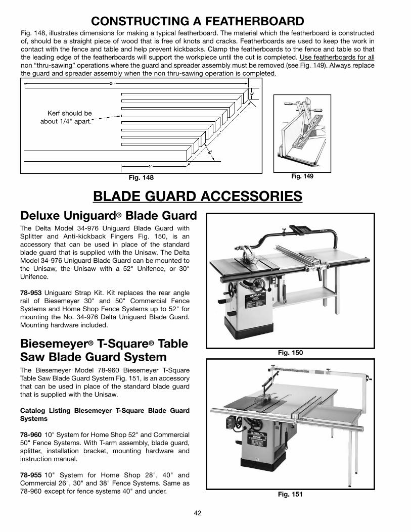
CONSTRUCTING A FEATHERBOARDFig. 148, illustrates dimensions for making a typical featherboard. The material which the featherboard is constructedof, should be a straight piece of wood that is free of knots and cracks. Featherboards are used to keep the work incontact with the fence and table and help prevent kickbacks. Clamp the featherboards to the fence and table so thatthe leading edge of the featherboards will support the workpiece until the cut is completed. Use featherboards for allnon “thru-sawing” operations where the guard and spreader assembly must be removed (see Fig. 149). Always replacethe guard and spreader assembly when the non thru-sawing operation is completed.
Fig. 148 Fig. 149
Kerf should beabout 1/4" apart.
BLADE GUARD ACCESSORIESDeluxe Uniguard® Blade GuardThe Delta Model 34-976 Uniguard Blade Guard withSplitter and Anti-kickback Fingers Fig. 150, is anaccessory that can be used in place of the standardblade guard that is supplied with the Unisaw. The DeltaModel 34-976 Uniguard Blade Guard can be mounted tothe Unisaw, the Unisaw with a 52" Unifence, or 30"Unifence.
78-953 Uniguard Strap Kit. Kit replaces the rear anglerail of Biesemeyer 30" and 50" Commercial FenceSystems and Home Shop Fence Systems up to 52" formounting the No. 34-976 Delta Uniguard Blade Guard.Mounting hardware included.
Fig. 150Biesemeyer® T-Square® TableSaw Blade Guard SystemThe Biesemeyer Model 78-960 Biesemeyer T-SquareTable Saw Blade Guard System Fig. 151, is an accessorythat can be used in place of the standard blade guardthat is supplied with the Unisaw.
Catalog Listing Blesemeyer T-Square Blade GuardSystems
78-960 10" System for Home Shop 52" and Commercial50" Fence Systems. With T-arm assembly, blade guard,splitter, installation bracket, mounting hardware andinstruction manual.
78-955 10" System for Home Shop 28", 40" andCommercial 26", 30" and 38" Fence Systems. Same as78-960 except for fence systems 40" and under. Fig. 151

43
ACCESSORIESA complete line of accessories is available from your Delta Supplier, Porter-Cable • Delta Factory Service Centers,and Delta Authorized Service Stations. Please visit our Web Site www.deltamachinery.com for a catalog orfor the name of your nearest supplier.
WARNING: Since accessories other than those offered by Delta have not been tested with this product, use of such accessories could be hazardous. For safest operation, only Delta recommended accessories should be used with this product.
PARTS, SERVICE OR WARRANTY ASSISTANCEAll Delta Machines and accessories are manufactured to high quality standards and are serviced by a network of Porter-Cable • Delta Factory Service Centers and Delta Authorized Service Stations. To obtain additional information regardingyour Delta quality product or to obtain parts, service, warranty assistance, or the location of the nearest service outlet,please call 1-800-223-7278 (In Canada call 1-800-463-3582).
Two Year Limited WarrantyDelta will repair or replace, at its expense and at its option, any Delta machine, machine part, or machine accessory whichin normal use has proven to be defective in workmanship or material, provided that the customer returns the productprepaid to a Delta factory service center or authorized service station with proof of purchase of the product within twoyears and provides Delta with reasonable opportunity to verify the alleged defect by inspection. Delta may require thatelectric motors be returned prepaid to a motor manufacturer’s authorized station for inspection and repair or replacement.Delta will not be responsible for any asserted defect which has resulted from normal wear, misuse, abuse or repair oralteration made or specifically authorized by anyone other than an authorized Delta service facility or representative. Underno circumstances will Delta be liable for incidental or consequential damages resulting from defective products. Thiswarranty is Delta’s sole warranty and sets forth the customer’s exclusive remedy, with respect to defective products; allother warranties, express or implied, whether of merchantability, fitness for purpose, or otherwise, are expresslydisclaimed by Delta.
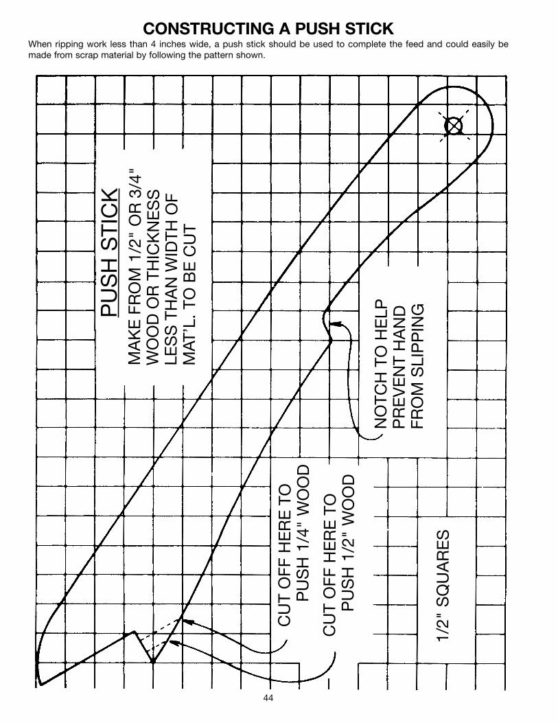
44
PU
SH
STI
CK
MA
KE
FRO
M 1
/2"
OR
3/4"
WO
OD
OR
THIC
KN
ES
SLE
SS
THA
NW
IDTH
OF
MAT
’L.
TOB
EC
UT
CU
TO
FFH
ER
ETO
PU
SH
1/4
" W
OO
D
CU
TO
FFH
ER
ETO
PU
SH
1/2
" W
OO
D
NO
TCH
TOH
ELP
PR
EV
EN
TH
AN
DFR
OM
SLI
PP
ING
1/2"
SQ
UA
RE
S
CONSTRUCTING A PUSH STICKWhen ripping work less than 4 inches wide, a push stick should be used to complete the feed and could easily bemade from scrap material by following the pattern shown.

45
NOTES

46
NOTES

47
NOTES

The following are trademarks of PORTER-CABLE·DELTA (Las siguientes son marcas registradas de PORTER-CABLE S.A.): Auto-Set®,BAMMER®, B.O.S.S.®, Builder’s Saw®, Contractor’s Saw®, Contractor’s Saw II™, Delta®, DELTACRAFT®, DELTAGRAM™, Delta Series2000™, DURATRONIC™, Emc²™, FLEX®, Flying Chips™, FRAME SAW®, Homecraft®, INNOVATION THAT WORKS®, Jet-Lock®,JETSTREAM®, ‘kickstand®, LASERLOC®, MICRO-SET®, Micro-Set®, MIDI LATHE®, MORTEN™, NETWORK™, OMNIJIG®, POCKETCUTTER®, PORTA-BAND®, PORTA-PLANE®, PORTER-CABLE®&(design), PORTER-CABLE®PROFESSIONAL POWER TOOLS, Posi-Matic®,Q-3®&(design), QUICKSAND®&(design), QUICKSET™, QUICKSET II®, QUICKSET PLUS™, RIPTIDE™&(design), SAFE GUARD II®, SAFE-LOC®, Sanding Center®, SANDTRAP®&(design), SAW BOSS®, Sawbuck™, Sidekick®, SPEED-BLOC®, SPEEDMATIC®, SPEEDTRONIC®,STAIR EASE®, The American Woodshop®&(design), The Lumber Company®&(design), THE PROFESSIONAL EDGE®, THE PROFESSIONALSELECT®, THIN-LINE™, TIGER®, TIGER CUB®, TIGER SAW®, TORQBUSTER®, TORQ-BUSTER®, TRU-MATCH™, TWIN-LITE®,UNIGUARD®, Unifence®, UNIFEEDER™, Unihead®, Uniplane™, Unirip®, Unisaw®, Univise®, Versa-Feeder®, VERSA-PLANE® , WHISPERSERIES®, WOODWORKER’S CHOICE™. Trademarks noted with ™ and ® are registered in the United States Patent and Trademark Office and may also be registered in othercountries. Las Marcas Registradas con el signo de ™ y ® son registradas por la Oficina de Registros y Patentes de los Estados Unidos ytambién pueden estar registradas en otros países.
PORTER-CABLE • DELTA SERVICE CENTERS(CENTROS DE SERVICIO DE PORTER-CABLE • DELTA)
Parts and Repair Service for Porter-Cable • Delta Machinery are Available at These Locations(Obtenga Refaccion de Partes o Servicio para su Herramienta en los Siguientes Centros de Porter-Cable • Delta)
Authorized Service Stations are located in many large cities. Telephone 800-438-2486 or 731-541-6042 for assistance locating one.Parts and accessories for Porter-Cable·Delta products should be obtained by contacting any Porter-Cable·Delta Distributor, AuthorizedService Center, or Porter-Cable·Delta Factory Service Center. If you do not have access to any of these, call 800-223-7278 and you willbe directed to the nearest Porter-Cable·Delta Factory Service Center. Las Estaciones de Servicio Autorizadas están ubicadas en muchasgrandes ciudades. Llame al 800-438-2486 ó al 731-541-6042 para obtener asistencia a fin de localizar una. Las piezas y los accesoriospara los productos Porter-Cable·Delta deben obtenerse poniéndose en contacto con cualquier distribuidor Porter-Cable·Delta, Centrode Servicio Autorizado o Centro de Servicio de Fábrica Porter-Cable·Delta. Si no tiene acceso a ninguna de estas opciones, llame al800-223-7278 y le dirigirán al Centro de Servicio de Fábrica Porter-Cable·Delta más cercano.
ARIZONATempe 85282 (Phoenix)2400 West Southern AvenueSuite 105Phone: (602) 437-1200Fax: (602) 437-2200
CALIFORNIAOntario 91761 (Los Angeles)3949A East Guasti RoadPhone: (909) 390-5555Fax: (909) 390-5554San Leandro 94577 (Oakland)3039 Teagarden StreetPhone: (510) 357-9762Fax: (510) 357-7939
COLORADOArvada 80003 (Denver)8175 Sheridan Blvd., Unit SPhone: (303) 487-1809Fax: (303) 487-1868
FLORIDADavie 33314 (Miami)4343 South State Rd. 7 (441)Unit #107Phone: (954) 321-6635Fax: (954) 321-6638
Tampa 33609 4538 W. Kennedy BoulevardPhone: (813) 877-9585Fax: (813) 289-7948
GEORGIAForest Park 30297 (Atlanta)5442 Frontage Road,Suite 112Phone: (404) 608-0006Fax: (404) 608-1123
ILLINOISAddison 60101 (Chicago)400 South Rohlwing Rd.Phone: (630) 424-8805Fax: (630) 424-8895
Woodridge 60517 (Chicago)2033 West 75th StreetPhone: (630) 910-9200Fax: (630) 910-0360
MARYLANDElkridge 21075 (Baltimore)7397-102 Washington Blvd.Phone: (410) 799-9394Fax: (410) 799-9398
MASSACHUSETTSBraintree 02185 (Boston)719 Granite StreetPhone: (781) 848-9810Fax: (781) 848-6759Franklin 02038 (Boston)Franklin Industrial Park101E Constitution Blvd.Phone: (508) 520-8802Fax: (508) 528-8089
MICHIGANMadison Heights 48071 (Detroit)30475 Stephenson HighwayPhone: (248) 597-5000Fax: (248) 597-5004
MINNESOTAMinneapolis 554295522 Lakeland Avenue NorthPhone: (763) 561-9080Fax: (763) 561-0653
MISSOURINorth Kansas City 641161141 Swift AvenuePhone: (816) 221-2070Fax: (816) 221-2897
St. Louis 631197574 Watson RoadPhone: (314) 968-8950Fax: (314) 968-2790
NEW YORKFlushing 11365-1595 (N.Y.C.)175-25 Horace Harding Expwy.Phone: (718) 225-2040Fax: (718) 423-9619
NORTH CAROLINACharlotte 282709129 Monroe Road, Suite 115Phone: (704) 841-1176Fax: (704) 708-4625
OHIOColumbus 432144560 Indianola AvenuePhone: (614) 263-0929Fax: (614) 263-1238
Cleveland 441258001 Sweet Valley DriveUnit #19Phone: (216) 447-9030Fax: (216) 447-3097
OREGONPortland 972304916 NE 122 nd Ave.Phone: (503) 252-0107Fax: (503) 252-2123
PENNSYLVANIAWillow Grove 19090520 North York RoadPhone: (215) 658-1430Fax: (215) 658-1433
TEXASCarrollton 75006 (Dallas)1300 Interstate 35 N, Suite 112Phone: (972) 446-2996Fax: (972) 446-8157
Houston 77055West 10 Business Center1008 Wirt Road, Suite 120Phone: (713) 682-0334Fax: (713) 682-4867
WASHINGTONAuburn 98001(Seattle)3320 West Valley HWY, NorthBuilding D, Suite 111Phone: (253) 333-8353Fax: (253) 333-9613
Printed in U.S.A.
CANADIAN PORTER-CABLE • DELTA SERVICE CENTERSALBERTABay 6, 2520-23rd St. N.E.Calgary, AlbertaT2E 8L2Phone: (403) 735-6166Fax: (403) 735-6144
BRITISH COLUMBIA8520 Baxter PlaceBurnaby, B.C.V5A 4T8Phone: (604) 420-0102Fax: (604) 420-3522
MANITOBA1699 Dublin AvenueWinnipeg, ManitobaR3H 0H2Phone: (204) 633-9259Fax: (204) 632-1976
ONTARIO505 Southgate DriveGuelph, OntarioN1H 6M7Phone: (519) 836-2840Fax: (519) 767-4131
QUÉBEC1515 ave.St-Jean Baptiste,Québec, QuébecG2E 5E2Phone: (418) 877-7112Fax: (418) 877-7123
1447, BeginSt-Laurent, (Montréal),QuébecH4R 1V8Phone: (514) 336-8772Fax: (514) 336-3505