Embed Size (px)
Citation preview
General Operating Instructions Measuring/Control Stations DULCOTROL® Drinking Water/F&B
ProM
inen
t®
Please enter the Identcode of your device
DULCOTROL® drinking water/F&B ___ ___ ___ ___ ___ ___ ___ ___ ___ ___ ___ ___ ___ ___ ___ ___
These general operating instructions facilitate the installation and calibration of the measuring panel inclusive of its individual component parts. All further processes such as for example the setting of specifi c limit and
control pa ram e ters are described in the individual operating instructions of the ProMinent® components. The individual operating instructions are enclosed with the measuring/control station DULCOTROL® drinking water/F&B.
Part no. 986421 ProMinent Dosiertechnik GmbH · 69123 Heidelberg · Germany BA DR 001 02/09 GB
These general operating instructions apply only in conjunction with the individual operating instructions of all supplied individual components.
Please completely read through all operating instructions! Do not discard! The operator shall be liable for any damage caused by installation or operating errors!
BA_DR_001_02_09_GB.indd 1BA_DR_001_02_09_GB.indd 1 24.02.2009 12:23:58 Uhr24.02.2009 12:23:58 Uhr
ProMinent®Page 2
Corporate information: General Operating Instructions Measuring/Control Stations DULCOTROL® Drinking Water/F&B
© ProMinent Dosiertechnik GmbH, 2008
ProMinent Dosiertechnik GmbH Im Schuhmachergewann 5-11 69123 Heidelberg
Telephone: +49 (6221) 842-0 Fax: +49 (6221) 842-617
[email protected] www.prominent.com
Technical changes reserved.
Corporate Information
BA_DR_001_02_09_GB.indd 2BA_DR_001_02_09_GB.indd 2 24.02.2009 12:23:58 Uhr24.02.2009 12:23:58 Uhr
ProMinent® Page 3
Contents
Page
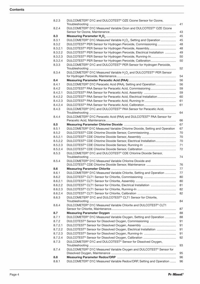
Identcode ................................................................................................................ 8General User Information ........................................................................................ 11
1 Safety Chapter ....................................................................................................... 12
1.1 Identifi cation of the Notes on Safety ....................................................................... 12 1.2 General Notes on Safety ......................................................................................... 12 1.3 Information for Emergencies ................................................................................... 13 1.4 Proper Use .............................................................................................................. 14 1.5 Qualifi cation of the Personnel ................................................................................. 14
2 Storage and Transport .......................................................................................... 14
3 About this Product ................................................................................................ 15
3.1 DULCOTROL® Drinking Water/F&B ......................................................................... 15
4 Overview of Measuring Stations .......................................................................... 15
4.1 DULCOTROL® Measuring/Control Station with In-line Probe DGMa ..................... 15 4.2 DULCOTROL® Measuring/Control Station with Fitting and In-line Probe DLG III ... 16 4.3 DULCOTROL® Measuring/Control Station, Installation Diagram ............................. 17
5 Mounting / Installation .......................................................................................... 17
5.1 Mounting (mechanical) ............................................................................................ 17 5.1.1 Measuring Station ................................................................................................... 18 5.1.2 Accessories ............................................................................................................. 19 5.2 Installation (hydraulic) .............................................................................................. 20 5.2.1 DULCOTROL® Measuring/Control Station .............................................................. 20 5.3 Installation of DULCOTROL® Measuring/Control Station (electrical) ....................... 20 5.3.1 Measuring Panel ...................................................................................................... 21 5.3.2 Sample Water Pump ............................................................................................... 21 5.4 Mounting of the Sensors ......................................................................................... 21 5.5 Hydraulic Test Run after Installation ........................................................................ 21 5.6 Installation of the Sensor (electrical) ....................................................................... 22
6 Commissioning of the Sensors ............................................................................ 22
6.1 Setting of the Flow Meter Switching Point .............................................................. 23 6.2 Running-In Period ................................................................................................... 23
7 Device Overview / Controls D1C / D2C General ................................................. 24
8 Measuring Parameters........................................................................................... 25
8.1 Measuring Parameter Free Chlorine .................................................................... 25 8.1.1 DULCOMETER® D1C Measured Variable Chlorine, Setting and Operation ............. 25 8.1.2 DULCOTEST® CLE Chlorine Sensor for Free Chlorine, Commissioning .................. 28 8.1.2.1 DULCOTEST® CLE Chlorine Sensor for Free Chlorine, Assembly ........................... 28 8.1.2.2 DULCOTEST® CLE Chlorine Sensor for Free Chlorine, Electrical Installation.......... 28 8.1.2.3 DULCOTEST® CLE Chlorine Sensor for Free Chlorine, Running-In ......................... 29 8.1.2.4 DULCOTEST® CLE Chlorine Sensor for Free Chlorine, Calibration ......................... 29 8.1.3 DULCOMETER® D1C and DULCOTEST® CLE Chlorine Sensor for Free Chlorine,
Troubleshooting ....................................................................................................... 31 8.1.4 DULCOMETER® D1C Measured Variable Chlorine and DULCOTEST® CLE
Chlorine Sensor, Maintenance ................................................................................ 33 8.2 Measuring Parameter Ozone ................................................................................ 34 8.2.1 DULCOMETER® D1C Measured Variable Ozone, Setting and Operation ................ 34 8.2.2 DULCOTEST® OZE Ozone Sensor, Commissioning ................................................ 37 8.2.2.1 DULCOTEST® OZE Ozone Sensor for Ozone, Assembly ........................................ 37 8.2.2.2 DULCOTEST® OZE Ozone Sensor, Electrical Installation ........................................ 38 8.2.2.3 DULCOTEST® OZE Ozone Sensor, Running-In........................................................ 38 8.2.2.4 DULCOTEST® OZE Ozone Sensor, Calibration ........................................................ 39
BA_DR_001_02_09_GB.indd 3BA_DR_001_02_09_GB.indd 3 24.02.2009 12:23:58 Uhr24.02.2009 12:23:58 Uhr
ProMinent®Page 4
Contents
8.2.3 DULCOMETER® D1C and DULCOTEST® OZE Ozone Sensor for Ozone, Troubleshooting ....................................................................................................... 41
8.2.4 DULCOMETER® D1C Measured Variable Ozon and DULCOTEST® OZE Ozone Sensor for Ozone, Maintenance ............................................................................... 43
8.3 Measuring Parameter H2O2 ................................................................................... 45 8.3.1 DULCOMETER® D1C Measured Variable H2O2, Setting and Operation .................. 45 8.3.2 DULCOTEST® PER Sensor for Hydrogen Peroxide, Commissioning ...................... 48 8.3.2.1 DULCOTEST® PER Sensor for Hydrogen Peroxide, Assembly ................................ 48 8.3.2.2 DULCOTEST® PER Sensor for Hydrogen Peroxide, Electrical Installation ............. 49 8.3.2.3 DULCOTEST® PER Sensor for Hydrogen Peroxide, Running-In .............................. 50 8.3.2.4 DULCOTEST® PER Sensor for Hydrogen Peroxide, Calibration .............................. 50 8.3.3 DULCOMETER® D1C and DULCOTEST® PER Sensor for Hydrogen Peroxide,
Troubleshooting ....................................................................................................... 52 8.3.4 DULCOMETER® D1C Measured Variable H2O2 and DULCOTEST® PER Sensor
for Hydrogen Peroxide, Maintenance ....................................................................... 54 8.4 Measuring Parameter Peracetic Acid (PAA) ........................................................ 56 8.4.1 DULCOMETER® D1C Peracetic Acid (PAA), Setting and Operation ........................ 56 8.4.2 DULCOTEST® PAA Sensor for Peracetic Acid, Commissioning .............................. 59 8.4.2.1 DULCOTEST® PAA Sensor for Peracetic Acid, Assembly ...................................... 59 8.4.2.2 DULCOTEST® PAA Sensor for Peracetic Acid, Electrical Installation ...................... 60 8.4.2.3 DULCOTEST® PAA Sensor for Peracetic Acid, Running-In ..................................... 61 8.4.2.4 DULCOTEST® PAA Sensor for Peracetic Acid, Calibration ...................................... 61 8.4.3 DULCOMETER® D1C and DULCOTEST® PAA Sensor for Peracetic Acid,
Troubleshooting ....................................................................................................... 64 8.4.4 DULCOMETER® D1C Peracetic Acid (PAA) and DULCOTEST® PAA Sensor for
Peracetic Acid, Maintenance.................................................................................... 66 8.5 Measuring Parameter Chlorine Dioxide .............................................................. 67 8.5.1 DULCOMETER® D1C Measured Variable Chlorine Dioxide, Setting and Operation 67 8.5.2 DULCOTEST® CDE Chlorine Dioxide Sensor, Commissioning ................................ 70 8.5.2.1 DULCOTEST® CDE Chlorine Dioxide Sensor, Assembly ......................................... 70 8.5.2.2 DULCOTEST® CDE Chlorine Dioxide Sensor, Electrical Installation ........................ 70 8.5.2.3 DULCOTEST® CDE Chlorine Dioxide Sensor, Running-In ...................................... 71 8.5.2.4 DULCOTEST® CDE Chlorine Dioxide Sensor, Calibration ....................................... 72 8.5.3 DULCOMETER® D1C and DULCOTEST® CDE Chlorine Dioxide Sensor,
Troubleshooting ....................................................................................................... 74 8.5.4 DULCOMETER® D1C Measured Variable Chlorine Dioxide and
DULCOTEST® CDE Chlorine Dioxide Sensor, Maintenance ................................... 76 8.6 Measuring Parameter Chlorite ............................................................................. 77 8.6.1 DULCOMETER® D1C Measured Variable Chlorite, Setting and Operation ............. 77 8.6.2 DULCOTEST® CLT1 Sensor for Chlorite, Commissioning ...................................... 80 8.6.2.1 DULCOTEST® CLT1 Sensor for Chlorite, Assembly ................................................ 80 8.6.2.2 DULCOTEST® CLT1 Sensor for Chlorite, Electrical Installation .............................. 81 8.6.2.3 DULCOTEST® CLT1 Sensor for Chlorite, Running-In .............................................. 82 8.6.2.4 DULCOTEST® CLT1 Sensor for Chlorite, Calibration .............................................. 82 8.6.3 DULCOMETER® D1C and DULCOTEST® CLT1 Sensor for Chlorite,
Troubleshooting ....................................................................................................... 84 8.6.4 DULCOMETER® D1C Measured Variable Chlorite and DULCOTEST® CLT1
Sensor for Chlorite, Maintenance ............................................................................. 87 8.7 Measuring Parameter Oxygen ............................................................................. 88 8.7.1 DULCOMETER® D1C Measured Variable Oxygen, Setting and Operation ............. 88 8.7.2 DULCOTEST® Sensor for Dissolved Oxygen, Commissioning ............................... 91 8.7.2.1 DULCOTEST® Sensor for Dissolved Oxygen, Assembly ........................................ 91 8.7.2.2 DULCOTEST® Sensor for Dissolved Oxygen, Electrical Installation ....................... 91 8.7.2.3 DULCOTEST® Sensor for Dissolved Oxygen, Running-In ...................................... 91 8.7.2.4 DULCOTEST® Sensor for Dissolved Oxygen, Calibration ....................................... 92 8.7.3 DULCOMETER® D1C and DULCOTEST® Sensor for Dissolved Oxygen,
Troubleshooting ....................................................................................................... 93 8.7.4 DULCOMETER® D1C Measured Variable Oxygen and DULCOTEST® Sensor for
Dissolved Oxygen, Maintenance ............................................................................. 95 8.8 Measuring Parameter Redox/ORP ...................................................................... 96 8.8.1 DULCOMETER® D1C Measured Variable Redox/ORP, Setting and Operation ....... 96
BA_DR_001_02_09_GB.indd 4BA_DR_001_02_09_GB.indd 4 24.02.2009 12:23:58 Uhr24.02.2009 12:23:58 Uhr
ProMinent® Page 5
Contents
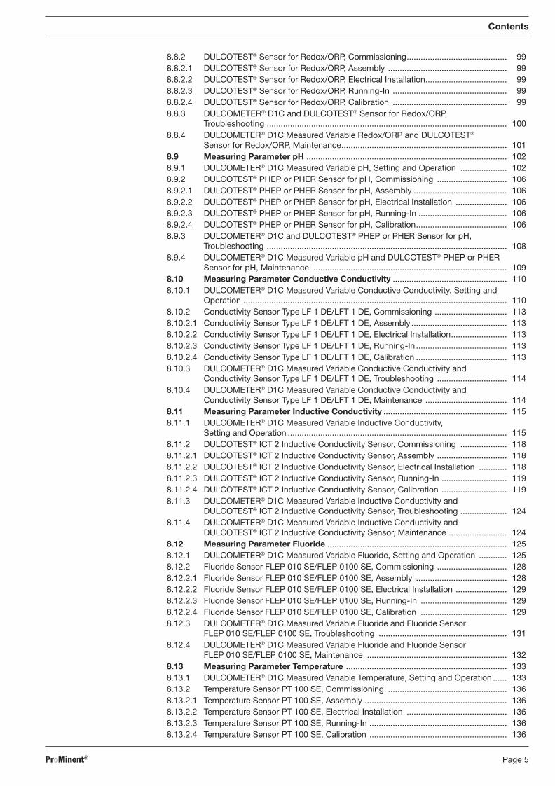
8.8.2 DULCOTEST® Sensor for Redox/ORP, Commissioning ........................................... 99 8.8.2.1 DULCOTEST® Sensor for Redox/ORP, Assembly ................................................... 99 8.8.2.2 DULCOTEST® Sensor for Redox/ORP, Electrical Installation ................................... 99 8.8.2.3 DULCOTEST® Sensor for Redox/ORP, Running-In ................................................. 99 8.8.2.4 DULCOTEST® Sensor for Redox/ORP, Calibration ................................................. 99 8.8.3 DULCOMETER® D1C and DULCOTEST® Sensor for Redox/ORP,
Troubleshooting ....................................................................................................... 100 8.8.4 DULCOMETER® D1C Measured Variable Redox/ORP and DULCOTEST®
Sensor for Redox/ORP, Maintenance ....................................................................... 101 8.9 Measuring Parameter pH ...................................................................................... 102 8.9.1 DULCOMETER® D1C Measured Variable pH, Setting and Operation .................... 102 8.9.2 DULCOTEST® PHEP or PHER Sensor for pH, Commissioning .............................. 106 8.9.2.1 DULCOTEST® PHEP or PHER Sensor for pH, Assembly ........................................ 106 8.9.2.2 DULCOTEST® PHEP or PHER Sensor for pH, Electrical Installation ...................... 106 8.9.2.3 DULCOTEST® PHEP or PHER Sensor for pH, Running-In ...................................... 106 8.9.2.4 DULCOTEST® PHEP or PHER Sensor for pH, Calibration ....................................... 106 8.9.3 DULCOMETER® D1C and DULCOTEST® PHEP or PHER Sensor for pH,
Troubleshooting ....................................................................................................... 108 8.9.4 DULCOMETER® D1C Measured Variable pH and DULCOTEST® PHEP or PHER
Sensor for pH, Maintenance ................................................................................... 109 8.10 Measuring Parameter Conductive Conductivity ................................................. 110 8.10.1 DULCOMETER® D1C Measured Variable Conductive Conductivity, Setting and
Operation ................................................................................................................. 110 8.10.2 Conductivity Sensor Type LF 1 DE/LFT 1 DE, Commissioning ............................... 113 8.10.2.1 Conductivity Sensor Type LF 1 DE/LFT 1 DE, Assembly ......................................... 113 8.10.2.2 Conductivity Sensor Type LF 1 DE/LFT 1 DE, Electrical Installation ........................ 113 8.10.2.3 Conductivity Sensor Type LF 1 DE/LFT 1 DE, Running-In ....................................... 113 8.10.2.4 Conductivity Sensor Type LF 1 DE/LFT 1 DE, Calibration ....................................... 113 8.10.3 DULCOMETER® D1C Measured Variable Conductive Conductivity and
Conductivity Sensor Type LF 1 DE/LFT 1 DE, Troubleshooting .............................. 114 8.10.4 DULCOMETER® D1C Measured Variable Conductive Conductivity and
Conductivity Sensor Type LF 1 DE/LFT 1 DE, Maintenance ................................... 114 8.11 Measuring Parameter Inductive Conductivity ..................................................... 115 8.11.1 DULCOMETER® D1C Measured Variable Inductive Conductivity,
Setting and Operation .............................................................................................. 115 8.11.2 DULCOTEST® ICT 2 Inductive Conductivity Sensor, Commissioning .................... 118 8.11.2.1 DULCOTEST® ICT 2 Inductive Conductivity Sensor, Assembly .............................. 118 8.11.2.2 DULCOTEST® ICT 2 Inductive Conductivity Sensor, Electrical Installation ............ 118 8.11.2.3 DULCOTEST® ICT 2 Inductive Conductivity Sensor, Running-In ............................ 119 8.11.2.4 DULCOTEST® ICT 2 Inductive Conductivity Sensor, Calibration ............................ 119 8.11.3 DULCOMETER® D1C Measured Variable Inductive Conductivity and
DULCOTEST® ICT 2 Inductive Conductivity Sensor, Troubleshooting .................... 124 8.11.4 DULCOMETER® D1C Measured Variable Inductive Conductivity and
DULCOTEST® ICT 2 Inductive Conductivity Sensor, Maintenance ......................... 124 8.12 Measuring Parameter Fluoride ............................................................................. 125 8.12.1 DULCOMETER® D1C Measured Variable Fluoride, Setting and Operation ............ 125 8.12.2 Fluoride Sensor FLEP 010 SE/FLEP 0100 SE, Commissioning .............................. 128 8.12.2.1 Fluoride Sensor FLEP 010 SE/FLEP 0100 SE, Assembly ....................................... 128 8.12.2.2 Fluoride Sensor FLEP 010 SE/FLEP 0100 SE, Electrical Installation ...................... 129 8.12.2.3 Fluoride Sensor FLEP 010 SE/FLEP 0100 SE, Running-In ..................................... 129 8.12.2.4 Fluoride Sensor FLEP 010 SE/FLEP 0100 SE, Calibration ..................................... 129 8.12.3 DULCOMETER® D1C Measured Variable Fluoride and Fluoride Sensor
FLEP 010 SE/FLEP 0100 SE, Troubleshooting ....................................................... 131 8.12.4 DULCOMETER® D1C Measured Variable Fluoride and Fluoride Sensor
FLEP 010 SE/FLEP 0100 SE, Maintenance ............................................................ 132 8.13 Measuring Parameter Temperature ..................................................................... 133 8.13.1 DULCOMETER® D1C Measured Variable Temperature, Setting and Operation ...... 133 8.13.2 Temperature Sensor PT 100 SE, Commissioning ................................................... 136 8.13.2.1 Temperature Sensor PT 100 SE, Assembly ............................................................. 136 8.13.2.2 Temperature Sensor PT 100 SE, Electrical Installation ........................................... 136 8.13.2.3 Temperature Sensor PT 100 SE, Running-In ........................................................... 136 8.13.2.4 Temperature Sensor PT 100 SE, Calibration ........................................................... 136
BA_DR_001_02_09_GB.indd 5BA_DR_001_02_09_GB.indd 5 24.02.2009 12:23:58 Uhr24.02.2009 12:23:58 Uhr
ProMinent®Page 6
Contents
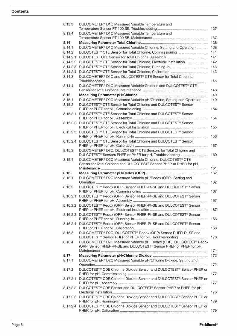
8.13.3 DULCOMETER® D1C Measured Variable Temperature and Temperature Sensor PT 100 SE, Troubleshooting ................................................... 137
8.13.4 DULCOMETER® D1C Measured Variable Temperature and Temperature Sensor PT 100 SE, Maintenance ........................................................ 137
8.14 Measuring Parameter Total Chlorine .................................................................... 138 8.14.1 DULCOMETER® D1C Measured Variable Chlorine, Setting and Operation ............ 138 8.14.2 DULCOTEST® CTE Sensor for Total Chlorine, Commissioning .............................. 141 8.14.2.1 DULCOTEST CTE Sensor for Total Chlorine, Assembly ......................................... 141 8.14.2.2 DULCOTEST® CTE Sensor for Total Chlorine, Electrical Installation ...................... 142 8.14.2.3 DULCOTEST® CTE Sensor for Total Chlorine, Running-In ...................................... 143 8.14.2.4 DULCOTEST® CTE Sensor for Total Chlorine, Calibration ...................................... 143 8.14.3 DULCOMETER® D1C and DULCOTEST® CTE Sensor for Total Chlorine,
Troubleshooting ........................................................................................................ 145 8.14.4 DULCOMETER® D1C Measured Variable Chlorine and DULCOTEST® CTE
Sensor for Total Chlorine, Maintenance .................................................................. 148 8.15 Measuring Parameter pH/Chlorine ...................................................................... 149 8.15.1 DULCOMETER® D2C Measured Variable pH/Chlorine, Setting and Operation ...... 149 8.15.2 DULCOTEST® CTE Sensor for Total Chlorine and DULCOTEST® Sensor
PHEP or PHER for pH, Commissioning .................................................................. 154 8.15.2.1 DULCOTEST® CTE Sensor for Total Chlorine and DULCOTEST® Sensor
PHEP or PHER for pH, Assembly ............................................................................ 154 8.15.2.2 DULCOTEST® CTE Sensor for Total Chlorine and DULCOTEST® Sensor
PHEP or PHER for pH, Electrical Installation .......................................................... 155 8.15.2.3 DULCOTEST® CTE Sensor for Total Chlorine and DULCOTEST® Sensor
PHEP or PHER for pH, Running-In .......................................................................... 156 8.15.2.4 DULCOTEST® CTE Sensor for Total Chlorine and DULCOTEST® Sensor
PHEP or PHER for pH, Calibration .......................................................................... 157 8.15.3 DULCOMETER® D2C, DULCOTEST® CTE Sensors for Total Chlorine and
DULCOTEST® Sensors PHEP or PHER for pH, Troubleshooting ............................ 160 8.15.4 DULCOMETER® D2C Measured Variable Chlorine, DULCOTEST® CTE
Sensor for Total Chlorine and DULCOTEST® Sensor PHEP or PHER for pH, Maintenance ............................................................................................................ 161
8.16 Measuring Parameter pH/Redox (ORP) .............................................................. 162 8.16.1 DULCOMETER® D2C Measured Variable pH/Redox (ORP), Setting and
Operation ................................................................................................................. 162 8.16.2 DULCOTEST® Redox (ORP) Sensor RHER-Pt-SE and DULCOTEST® Sensor
PHEP or PHER for pH, Commissioning .................................................................. 167 8.16.2.1 DULCOTEST® Redox (ORP) Sensor RHER-Pt-SE and DULCOTEST® Sensor
PHEP or PHER for pH, Assembly ............................................................................ 167 8.16.2.2 DULCOTEST® Redox (ORP) Sensor RHER-Pt-SE and DULCOTEST® Sensor
PHEP or PHER for pH, Electrical Installation ........................................................... 167 8.16.2.3 DULCOTEST® Redox (ORP) Sensor RHER-Pt-SE and DULCOTEST® Sensor
PHEP or PHER for pH, Running-In........................................................................... 168 8.16.2.4 DULCOTEST® Redox (ORP) Sensor RHER-Pt-SE and DULCOTEST® Sensor
PHEP or PHER for pH, Calibration ........................................................................... 168 8.16.3 DULCOMETER® D2C, DULCOTEST® Redox (ORP) Sensor RHER-Pt-SE and
DULCOTEST® Sensor PHEP or PHER for pH, Troubleshooting ............................. 170 8.16.4 DULCOMETER® D2C Measured Variable pH, Redox (ORP), DULCOTEST® Redox
(ORP) Sensor RHER-Pt-SE and DULCOTEST® Sensor PHEP or PHER for pH, Maintenance ............................................................................................................ 171
8.17 Measuring Parameter pH/Chlorine Dioxide ........................................................ 172 8.17.1 DULCOMETER® D2C Measured Variable pH/Chlorine Dioxide, Setting and
Operation .................................................................................................................. 172 8.17.2 DULCOTEST® CDE Chlorine Dioxide Sensor and DULCOTEST® Sensor PHEP or
PHER for pH, Commissioning ................................................................................. 177 8.17.2.1 DULCOTEST® CDE Chlorine Dioxide Sensor and DULCOTEST® Sensor PHEP or
PHER for pH, Assembly .......................................................................................... 177 8.17.2.2 DULCOTEST® CDE Sensor and DULCOTEST® Sensor PHEP or PHER for pH,
Electrical Installation ................................................................................................. 178 8.17.2.3 DULCOTEST® CDE Chlorine Dioxide Sensor and DULCOTEST® Sensor PHEP or
PHER for pH, Running-In ........................................................................................ 179 8.17.2.4 DULCOTEST® CDE Chlorine Dioxide Sensor and DULCOTEST® Sensor PHEP or
PHER for pH, Calibration ......................................................................................... 179
BA_DR_001_02_09_GB.indd 6BA_DR_001_02_09_GB.indd 6 24.02.2009 12:23:58 Uhr24.02.2009 12:23:58 Uhr
ProMinent® Page 7
Contents
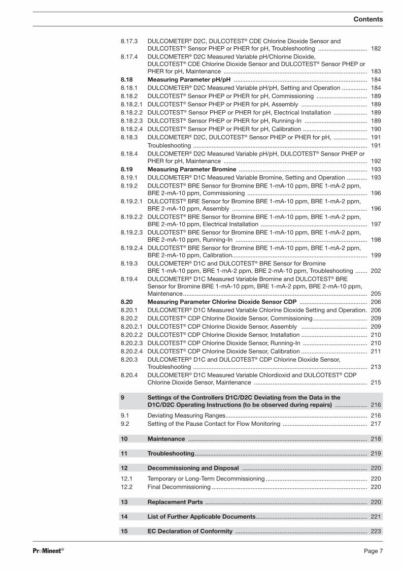
8.17.3 DULCOMETER® D2C, DULCOTEST® CDE Chlorine Dioxide Sensor and DULCOTEST® Sensor PHEP or PHER for pH, Troubleshooting ............................. 182
8.17.4 DULCOMETER® D2C Measured Variable pH/Chlorine Dioxide, DULCOTEST® CDE Chlorine Dioxide Sensor and DULCOTEST® Sensor PHEP or PHER for pH, Maintenance ..................................................................................... 183
8.18 Measuring Parameter pH/pH ............................................................................... 184 8.18.1 DULCOMETER® D2C Measured Variable pH/pH, Setting and Operation ............... 184 8.18.2 DULCOTEST® Sensor PHEP or PHER for pH, Commissioning .............................. 189 8.18.2.1 DULCOTEST® Sensor PHEP or PHER for pH, Assembly ....................................... 189 8.18.2.2 DULCOTEST® Sensor PHEP or PHER for pH, Electrical Installation .................... 189 8.18.2.3 DULCOTEST® Sensor PHEP or PHER for pH, Running-In ..................................... 189 8.18.2.4 DULCOTEST® Sensor PHEP or PHER for pH, Calibration ...................................... 190 8.18.3 DULCOMETER® D2C, DULCOTEST® Sensor PHEP or PHER for pH, .................... 191 Troubleshooting ....................................................................................................... 191 8.18.4 DULCOMETER® D2C Measured Variable pH/pH, DULCOTEST® Sensor PHEP or
PHER for pH, Maintenance ..................................................................................... 192 8.19 Measuring Parameter Bromine ............................................................................ 193 8.19.1 DULCOMETER® D1C Measured Variable Bromine, Setting and Operation ............ 193 8.19.2 DULCOTEST® BRE Sensor for Bromine BRE 1-mA-10 ppm, BRE 1-mA-2 ppm,
BRE 2-mA-10 ppm, Commissioning ....................................................................... 196 8.19.2.1 DULCOTEST® BRE Sensor for Bromine BRE 1-mA-10 ppm, BRE 1-mA-2 ppm,
BRE 2-mA-10 ppm, Assembly ................................................................................ 196 8.19.2.2 DULCOTEST® BRE Sensor for Bromine BRE 1-mA-10 ppm, BRE 1-mA-2 ppm,
BRE 2-mA-10 ppm, Electrical Installation ............................................................... 197 8.19.2.3 DULCOTEST® BRE Sensor for Bromine BRE 1-mA-10 ppm, BRE 1-mA-2 ppm,
BRE 2-mA-10 ppm, Running-In .............................................................................. 198 8.19.2.4 DULCOTEST® BRE Sensor for Bromine BRE 1-mA-10 ppm, BRE 1-mA-2 ppm,
BRE 2-mA-10 ppm, Calibration................................................................................ 199 8.19.3 DULCOMETER® D1C and DULCOTEST® BRE Sensor for Bromine
BRE 1-mA-10 ppm, BRE 1-mA-2 ppm, BRE 2-mA-10 ppm, Troubleshooting ....... 202 8.19.4 DULCOMETER® D1C Measured Variable Bromine and DULCOTEST® BRE
Sensor for Bromine BRE 1-mA-10 ppm, BRE 1-mA-2 ppm, BRE 2-mA-10 ppm, Maintenance ............................................................................................................. 205
8.20 Measuring Parameter Chlorine Dioxide Sensor CDP ........................................ 206 8.20.1 DULCOMETER® D1C Measured Variable Chlorine Dioxide Setting and Operation . 206 8.20.2 DULCOTEST® CDP Chlorine Dioxide Sensor, Commissioning ................................ 209 8.20.2.1 DULCOTEST® CDP Chlorine Dioxide Sensor, Assembly ....................................... 209 8.20.2.2 DULCOTEST® CDP Chlorine Dioxide Sensor, Installation ....................................... 210 8.20.2.3 DULCOTEST® CDP Chlorine Dioxide Sensor, Running-In ...................................... 210 8.20.2.4 DULCOTEST® CDP Chlorine Dioxide Sensor, Calibration ....................................... 211 8.20.3 DULCOMETER® D1C and DULCOTEST® CDP Chlorine Dioxide Sensor,
Troubleshooting ....................................................................................................... 213 8.20.4 DULCOMETER® D1C Measured Variable Chlordioxid and DULCOTEST® CDP
Chlorine Dioxide Sensor, Maintenance ................................................................... 215
9 Settings of the Controllers D1C/D2C Deviating from the Data in the D1C/D2C Operating Instructions (to be observed during repairs) ................... 216
9.1 Deviating Measuring Ranges.................................................................................... 216 9.2 Setting of the Pause Contact for Flow Monitoring .................................................. 217
10 Maintenance .......................................................................................................... 218
11 Troubleshooting ...................................................................................................... 219
12 Decommissioning and Disposal .......................................................................... 220
12.1 Temporary or Long-Term Decommissioning ............................................................ 220 12.2 Final Decommissioning ............................................................................................ 220
13 Replacement Parts ................................................................................................ 220
14 List of Further Applicable Documents .................................................................. 221
15 EC Declaration of Conformity .............................................................................. 223
BA_DR_001_02_09_GB.indd 7BA_DR_001_02_09_GB.indd 7 24.02.2009 12:23:58 Uhr24.02.2009 12:23:58 Uhr
ProMinent®Page 8
Identcode
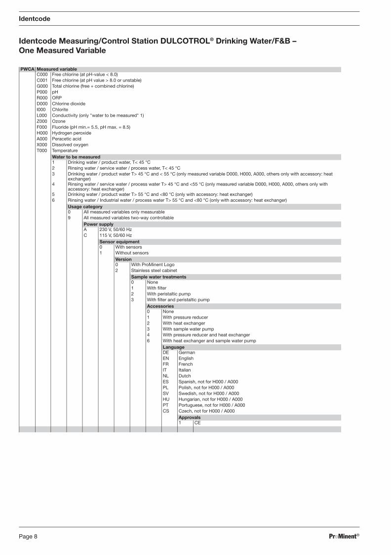
Identcode Measuring/Control Station DULCOTROL® Drinking Water/F&B – One Measured Variable
PWCA Measured variableC000 Free chlorine (at pH-value < 8.0)C001 Free chlorine (at pH value > 8.0 or unstable)G000 Total chlorine (free + combined chlorine)P000 pHR000 ORPD000 Chlorine dioxideI000 ChloriteL000 Conductivity (only "water to be measured" 1)Z000 OzoneF000 Fluoride (pH min.= 5.5, pH max. = 8.5) H000 Hydrogen peroxideA000 Peracetic acidX000 Dissolved oxygenT000 Temperature
Water to be measured1 Drinking water / product water, T< 45 °C2 Rinsing water / service water / process water, T< 45 °C3 Drinking water / product water T> 45 °C and < 55 °C (only measured variable D000, H000, A000, others only with accessory: heat
exchanger)4 Rinsing water / service water / process water T> 45 °C and <55 °C (only measured variable D000, H000, A000, others only with
accessory: heat exchanger)5 Drinking water / product water T> 55 °C and <80 °C (only with accessory: heat exchanger)6 Rinsing water / Industrial water / process water T> 55 °C and <80 °C (only with accessory: heat exchanger)
Usage category0 All measured variables only measurable9 All measured variables two-way controllable
Power supplyA 230 V, 50/60 HzC 115 V, 50/60 Hz
Sensor equipment0 With sensors1 Without sensors
Version0 With ProMinent Logo2 Stainless steel cabinet
Sample water treatments0 None1 With filter2 With peristaltic pump3 With filter and peristaltic pump
Accessories0 None1 With pressure reducer2 With heat exchanger3 With sample water pump4 With pressure reducer and heat exchanger6 With heat exchanger and sample water pump
LanguageDE GermanEN EnglishFR FrenchIT ItalianNL DutchES Spanish, not for H000 / A000PL Polish, not for H000 / A000SV Swedish, not for H000 / A000HU Hungarian, not for H000 / A000PT Portuguese, not for H000 / A000CS Czech, not for H000 / A000
Approvals1 CE
BA_DR_001_02_09_GB.indd 8BA_DR_001_02_09_GB.indd 8 24.02.2009 12:23:58 Uhr24.02.2009 12:23:58 Uhr
ProMinent® Page 9
Identcode
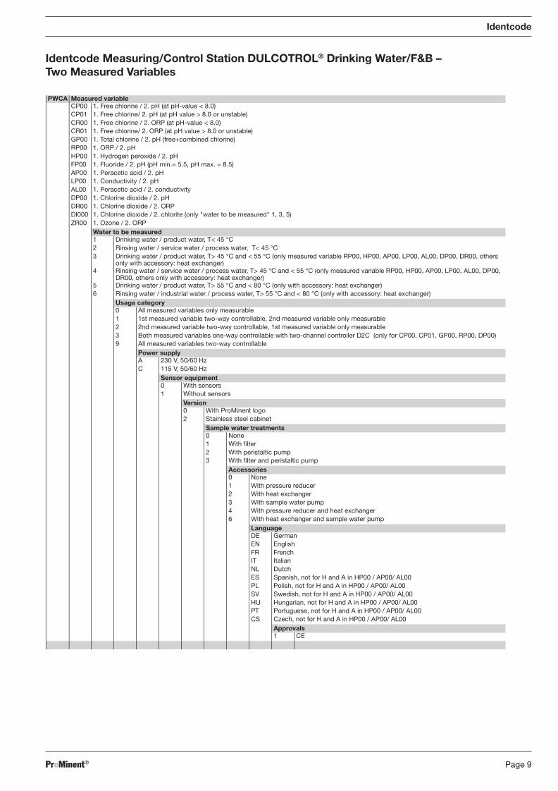
Identcode Measuring/Control Station DULCOTROL® Drinking Water/F&B – Two Measured Variables
PWCA Measured variableCP00 1. Free chlorine / 2. pH (at pH-value < 8.0)CP01 1. Free chlorine/ 2. pH (at pH value > 8.0 or unstable)CR00 1. Free chlorine / 2. ORP (at pH-value < 8.0)CR01 1. Free chlorine/ 2. ORP (at pH value > 8.0 or unstable)GP00 1. Total chlorine / 2. pH (free+combined chlorine)RP00 1. ORP / 2. pHHP00 1. Hydrogen peroxide / 2. pHFP00 1. Fluoride / 2. pH (pH min.= 5.5, pH max. = 8.5)AP00 1. Peracetic acid / 2. pHLP00 1. Conductivity / 2. pHAL00 1. Peracetic acid / 2. conductivityDP00 1. Chlorine dioxide / 2. pHDR00 1. Chlorine dioxide / 2. ORPDI000 1. Chlorine dioxide / 2. chlorite (only "water to be measured" 1, 3, 5)ZR00 1. Ozone / 2. ORP
Water to be measured1 Drinking water / product water, T< 45 °C2 Rinsing water / service water / process water, T< 45 °C3 Drinking water / product water, T> 45 °C and < 55 °C (only measured variable RP00, HP00, AP00, LP00, AL00, DP00, DR00, others
only with accessory: heat exchanger)4 Rinsing water / service water / process water, T> 45 °C and < 55 °C (only measured variable RP00, HP00, AP00, LP00, AL00, DP00,
DR00, others only with accessory: heat exchanger)5 Drinking water / product water, T> 55 °C and < 80 °C (only with accessory: heat exchanger)6 Rinsing water / industrial water / process water, T> 55 °C and < 80 °C (only with accessory: heat exchanger)
Usage category0 All measured variables only measurable1 1st measured variable two-way controllable, 2nd measured variable only measurable2 2nd measured variable two-way controllable, 1st measured variable only measurable3 Both measured variables one-way controllable with two-channel controller D2C (only for CP00, CP01, GP00, RP00, DP00)9 All measured variables two-way controllable
Power supplyA 230 V, 50/60 HzC 115 V, 50/60 Hz
Sensor equipment0 With sensors1 Without sensors
Version0 With ProMinent logo2 Stainless steel cabinet
Sample water treatments0 None1 With filter2 With peristaltic pump3 With filter and peristaltic pump
Accessories0 None1 With pressure reducer2 With heat exchanger3 With sample water pump4 With pressure reducer and heat exchanger6 With heat exchanger and sample water pump
LanguageDE GermanEN EnglishFR FrenchIT ItalianNL DutchES Spanish, not for H and A in HP00 / AP00/ AL00PL Polish, not for H and A in HP00 / AP00/ AL00SV Swedish, not for H and A in HP00 / AP00/ AL00HU Hungarian, not for H and A in HP00 / AP00/ AL00PT Portuguese, not for H and A in HP00 / AP00/ AL00CS Czech, not for H and A in HP00 / AP00/ AL00
Approvals1 CE
BA_DR_001_02_09_GB.indd 9BA_DR_001_02_09_GB.indd 9 24.02.2009 12:23:59 Uhr24.02.2009 12:23:59 Uhr
ProMinent®Page 10
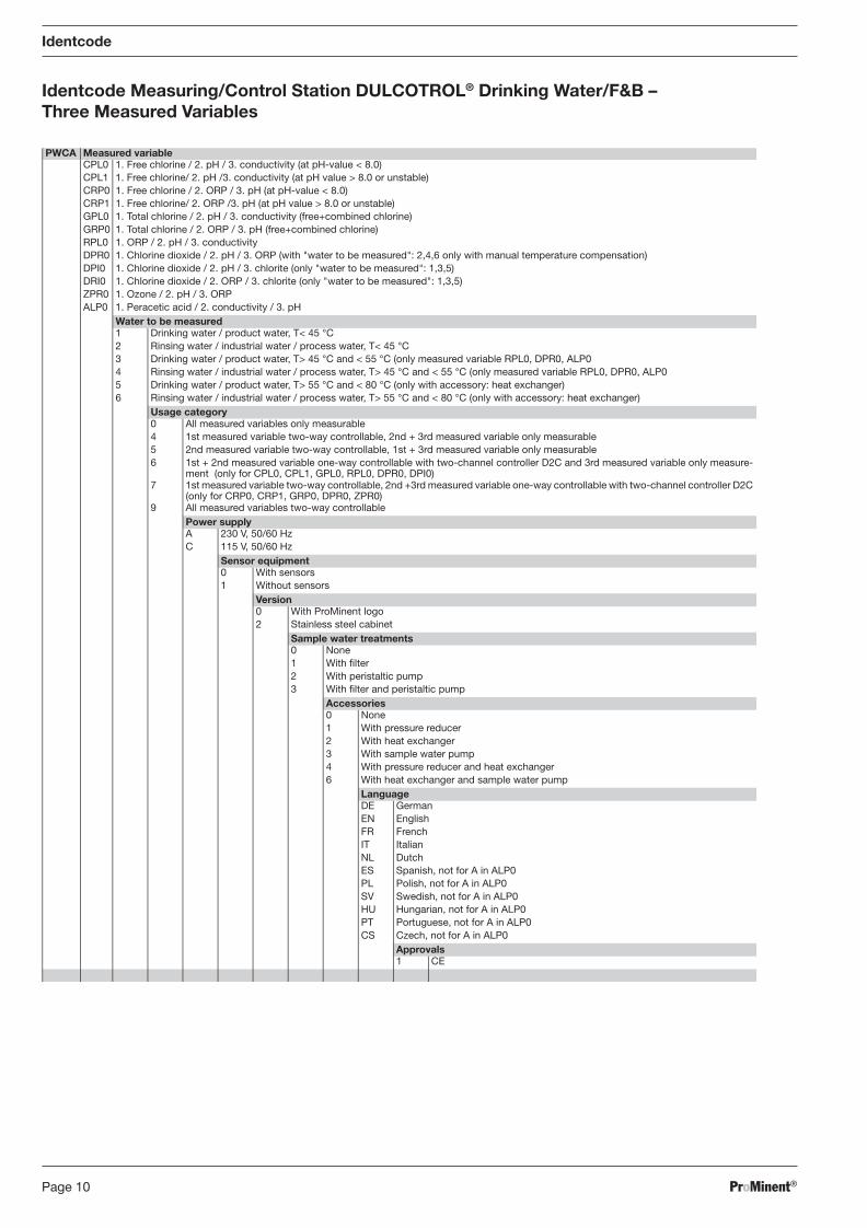
Identcode Measuring/Control Station DULCOTROL® Drinking Water/F&B – Three Measured Variables
Identcode
PWCA Measured variableCPL0 1. Free chlorine / 2. pH / 3. conductivity (at pH-value < 8.0)CPL1 1. Free chlorine/ 2. pH /3. conductivity (at pH value > 8.0 or unstable)CRP0 1. Free chlorine / 2. ORP / 3. pH (at pH-value < 8.0)CRP1 1. Free chlorine/ 2. ORP /3. pH (at pH value > 8.0 or unstable)GPL0 1. Total chlorine / 2. pH / 3. conductivity (free+combined chlorine)GRP0 1. Total chlorine / 2. ORP / 3. pH (free+combined chlorine)RPL0 1. ORP / 2. pH / 3. conductivityDPR0 1. Chlorine dioxide / 2. pH / 3. ORP (with "water to be measured": 2,4,6 only with manual temperature compensation)DPI0 1. Chlorine dioxide / 2. pH / 3. chlorite (only "water to be measured": 1,3,5)DRI0 1. Chlorine dioxide / 2. ORP / 3. chlorite (only "water to be measured": 1,3,5)ZPR0 1. Ozone / 2. pH / 3. ORPALP0 1. Peracetic acid / 2. conductivity / 3. pH
Water to be measured1 Drinking water / product water, T< 45 °C2 Rinsing water / industrial water / process water, T< 45 °C3 Drinking water / product water, T> 45 °C and < 55 °C (only measured variable RPL0, DPR0, ALP04 Rinsing water / industrial water / process water, T> 45 °C and < 55 °C (only measured variable RPL0, DPR0, ALP05 Drinking water / product water, T> 55 °C and < 80 °C (only with accessory: heat exchanger)6 Rinsing water / industrial water / process water, T> 55 °C and < 80 °C (only with accessory: heat exchanger)
Usage category0 All measured variables only measurable4 1st measured variable two-way controllable, 2nd + 3rd measured variable only measurable5 2nd measured variable two-way controllable, 1st + 3rd measured variable only measurable6 1st + 2nd measured variable one-way controllable with two-channel controller D2C and 3rd measured variable only measure-
ment (only for CPL0, CPL1, GPL0, RPL0, DPR0, DPI0)7 1st measured variable two-way controllable, 2nd +3rd measured variable one-way controllable with two-channel controller D2C
(only for CRP0, CRP1, GRP0, DPR0, ZPR0)9 All measured variables two-way controllable
Power supplyA 230 V, 50/60 HzC 115 V, 50/60 Hz
Sensor equipment0 With sensors1 Without sensors
Version0 With ProMinent logo2 Stainless steel cabinet
Sample water treatments0 None1 With filter2 With peristaltic pump3 With filter and peristaltic pump
Accessories0 None1 With pressure reducer2 With heat exchanger3 With sample water pump4 With pressure reducer and heat exchanger6 With heat exchanger and sample water pump
LanguageDE GermanEN EnglishFR FrenchIT ItalianNL DutchES Spanish, not for A in ALP0PL Polish, not for A in ALP0SV Swedish, not for A in ALP0HU Hungarian, not for A in ALP0PT Portuguese, not for A in ALP0CS Czech, not for A in ALP0
Approvals1 CE
BA_DR_001_02_09_GB.indd 10BA_DR_001_02_09_GB.indd 10 24.02.2009 12:23:59 Uhr24.02.2009 12:23:59 Uhr
ProMinent® Page 11
General User Information
General User Information
Please read through the following user guidelines! Familiarity with these points ensures optimum use of the operating instructions.
Key points in the text are indicated as follows:
• Enumerations
� Hints
Working guidelines:
NOTE
A note is to facilitate your work.
Notes on safety are identifi ed by pictographs.
BA_DR_001_02_09_GB.indd 11BA_DR_001_02_09_GB.indd 11 24.02.2009 12:23:59 Uhr24.02.2009 12:23:59 Uhr
ProMinent®Page 12
Safety Chapter
1 Safety Chapter
1.1 Identifi cation of the Notes on Safety
The following terms are used in the present operating instructions to indicate the various severity levels of the danger:
DANGER
Characterizes a possibly hazardous situation. There is a danger of death or serious injuries if these notes are disregarded.
WARNING
Characterizes a possibly hazardous situation. Your life is in danger and there is a danger of serious injury or death if these notes are disregarded!
CAUTION
Characterizes a possibly hazardous situation. There is a danger of slight or minor injury or damage to property if these notes are disregarded.
NOTE
A note provides important notes for the correct functioning of the unit or is to facilitate your work.
The following warning signs are used in the present operating instructions to indicate different types of the danger:
Warning of danger area
Warning of hazardous electrical voltage
Warning of caustic substances
Warning of hot surfaces
Warning of unexpected start
1.2 General Notes on Safety
WARNING
• Live parts!
• Disconnect from mains plug before opening the housing.
• De-energise damaged, defective or manipulated units by disconnecting the mains plug.
WARNING
• Hot surfaces!
• Risk of burning at the surfaces of the measuring station.
• For sample water > 55 °C, a temperature monitor with solenoid valve has to be installed to protect the DULCOTROL® measuring/control station. The temperature monitor is not included in the scope of delivery and must be installed by the customer.
• Suitable measures must be taken to prevent that nobody gets into contact with hot surfaces.
BA_DR_001_02_09_GB.indd 12BA_DR_001_02_09_GB.indd 12 24.02.2009 12:23:59 Uhr24.02.2009 12:23:59 Uhr
ProMinent® Page 13
Safety Chapter
WARNING
• Hazardous substances!
• Hazards from contact, inhalation or other contamination with/by substances or media!
• Observe the safety data sheet of the used substance/media.
• The operator of the DULCOTROL® measuring/control station is responsible for the fact that the safety data sheets are available and up-to-date.
WARNING
• Unexpected start of the DULCOTROL® measuring/control station after failure, malfunc-tion of the control/voltage supply or as intended action because of a control process!
• Hazards from unexpected actions of the stations!
• In case of malfunction/failure of the control or voltage supply, the DULCOTROL® meas-uring/control station is to be disconnected from the voltage supply. For further informa-tion see the operating instructions of the DULCOMETER® D1C units and sensors.
WARNING
• Operating error!
• Hazards from operating errors!
• The DULCOTROL® measuring/control stations may only be operated by suffi ciently qualifi ed and trained personnel.
WARNING
• Electrical hazards from lightning!
• Hazards from overvoltage because of lightning stroke into external installations which are connected to the DULCOTROL® measuring/control station.
• Do neither directly nor indirectly use the DULCOTROL® measuring/control station for use in the open.
• Provide for suffi cient potential to ground when installing electrical components.
NOTE
• Protect the DULCOTROL® measuring/control stations against unauthorised access!
• Please also read the operating instructions of the controllers and fi ttings and any other existing assemblies such as sensors, sample water pump … !
• Please observe the resistance of the materials of all assemblies in contact with the media. (see e.g. the ProMinent resistance list in the product catalogue or at www.prominent.com.)!
• Protect the DULCOTROL® measuring/control station against direct exposure to the sun and other UV sources!
• Please observe the basic rules of ergonomic principles!
1.3 Information for Emergencies
• Electrical emergency: Switch off the DULCOTROL® measuring/control station via the mains switch, at the terminal box or at the place specifi ed by the operator!
• Hydraulical emergency: Close the DULCOTROL® measuring/control station at the inlet- or outlet-side ball valve, observe the safety data sheet of the medium!
BA_DR_001_02_09_GB.indd 13BA_DR_001_02_09_GB.indd 13 24.02.2009 12:23:59 Uhr24.02.2009 12:23:59 Uhr
ProMinent®Page 14
1.4 Proper Use
• The DULCOTROL® measuring/control stations are only designed to measure or control liquid metering media in accordance with the Identcode feature specifi ed on the rating plate of the measuring/control station.
• The DULCOTROL® measuring/control stations are not designed to meter or control gaseous or solid media.
• The DULCOTROL® measuring/control stations may only be used in compliance with the technical data and specifi cations stated in these operating instructions and the operating instructions of the individual components!
• You are obliged to observe the information in the operating instructions on the various life phases of the DULCOTROL® measuring/control stations (such as assembly, installation, …)!
• The DULCOTROL® measuring/control stations may not be used for applications in the open.
• All other uses or modifi cations of the DULCOTROL® measuring/control stations require the prior written consent of ProMinent Dosiertechnik GmbH, Heidelberg, Germany.
• The DULCOTROL® measuring/control stations may only be operated by suffi ciently qualifi ed personnel (see table below). The operator of the DULCOTROL® measuring/control station is responsible for the qualifi cation of the personnel.
1.5 Qualifi cation of the Personnel
Safety Chapter / Storage and Transport
Tasks Qualifi cation
Mounting, installation, hydraulical Qualifi ed employee
Installation, electrical Qualifi ed employee
Commissioning Trained user
Maintenance Trained person
Troubleshooting Qualifi ed employee
Disposal Trained person
2 Storage and Transport
CAUTION
• Before storing or transporting, the DULCOTROL® measuring/control stations must be free from metering media and water!
• Only transport and store the DULCOTROL® measuring/control station in its original packaging!
• Protect the packaged DULCOTROL® measuring/control station also against moisture and exposure to chemicals and mechanical infl uences!
• Please also read the operating instructions of the controllers and fi ttings and any other existing assemblies such as sensors, sample water pump … !
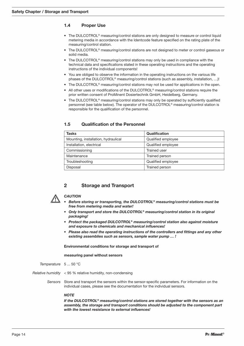
Environmental conditions for storage and transport of
measuring panel without sensors
Temperature 5 ... 50 °C
Relative humidity < 95 % relative humidity, non-condensing
Sensors Store and transport the sensors within the sensor-specifi c parameters. For information on the individual cases, please see the documentation for the individual sensors.
NOTE
If the DULCOTROL® measuring/control stations are stored together with the sensors as an assembly, the storage and transport conditions should be adjusted to the component part with the lowest resistance to external infl uences!
BA_DR_001_02_09_GB.indd 14BA_DR_001_02_09_GB.indd 14 24.02.2009 12:23:59 Uhr24.02.2009 12:23:59 Uhr
ProMinent® Page 15
3 About this Product
3.1 DULCOTROL® Drinking Water/F&B
DULCOTROL® measuring/control stations are complete and compact online process measuring/control stations mounted on a PE panel which are installed into a process water bypass.
1-3 measured variables can be confi gured on one single panel specifi c to the sample water. The measuring devices can be equipped with a measuring function and numerous control functions as required.
Optionally, a fi lter, pressure reducer, heat exchanger, and/or a sample water pump can be ordered for sample water conditioning. These are installed beyond the panel.
Measurement panels from two controllers onward include a terminal box for a safe electrical connection. All connecting cables are routed in a cable conduit.
The measuring/control stations DULCOTROL® drinking water/F&B are specifi cally designed for the drinking water industry as well as the food and beverages industry. Furthermore, the special requirements are met which are given on the part of the drinking water / product water treatment and the rinsing water, industrial water, and process water treatment.
In the following Identcode, the feature “water to be measured” is thus differentiated into:
• “drinking/product water treatment”: this means the fi nal treatment (e.g. disinfection) of water similar to drinking water as performed in the production of drinking water or in the production of beverages or food
• rinsing/industrial/process water: this includes e.g. all rinsing processes in the food and beverages industry aimed at the cleaning and disinfection of pipings, vessels and machines or process or industrial water with a higher level of contamination.
Scope of delivery Check the scope of delivery based on the delivery note and the Identcode!
4 Overview of Measuring Stations
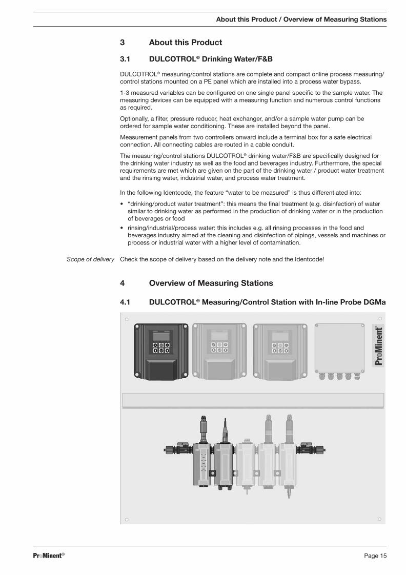
4.1 DULCOTROL® Measuring/Control Station with In-line Probe DGMa
About this Product / Overview of Measuring Stations
BA_DR_001_02_09_GB.indd 15BA_DR_001_02_09_GB.indd 15 24.02.2009 12:23:59 Uhr24.02.2009 12:23:59 Uhr
ProMinent®Page 16
Overview of Measuring Stations
The measuring panel DULCOTROL® measuring/control station with fi tting and in-line probe DGMa is produced in a customer-specifi c confi guration. It consists of at least one D1C controller, a sensor and the in-line probe DGMa with one measuring module. Depending on the customer’s needs it can be extended by further components which are greyed out here. In case of more than one controller, a terminal box is added for the electrical installation.
Optionally, a compatible fi lter, pressure reducer, heat exchanger, and/or a sample water pump can be ordered for sample water conditioning.
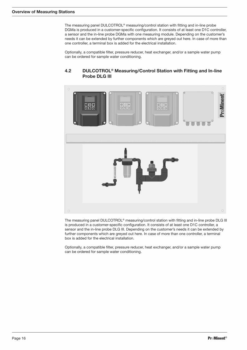
4.2 DULCOTROL® Measuring/Control Station with Fitting and In-line Probe DLG III
The measuring panel DULCOTROL® measuring/control station with fi tting and in-line probe DLG III is produced in a customer-specifi c confi guration. It consists of at least one D1C controller, a sensor and the in-line probe DLG III. Depending on the customer’s needs it can be extended by further components which are greyed out here. In case of more than one controller, a terminal box is added for the electrical installation.
Optionally, a compatible fi lter, pressure reducer, heat exchanger, and/or a sample water pump can be ordered for sample water conditioning.
BA_DR_001_02_09_GB.indd 16BA_DR_001_02_09_GB.indd 16 24.02.2009 12:24:00 Uhr24.02.2009 12:24:00 Uhr
ProMinent® Page 17
Overview of Measuring Stations / Mounting/Installation
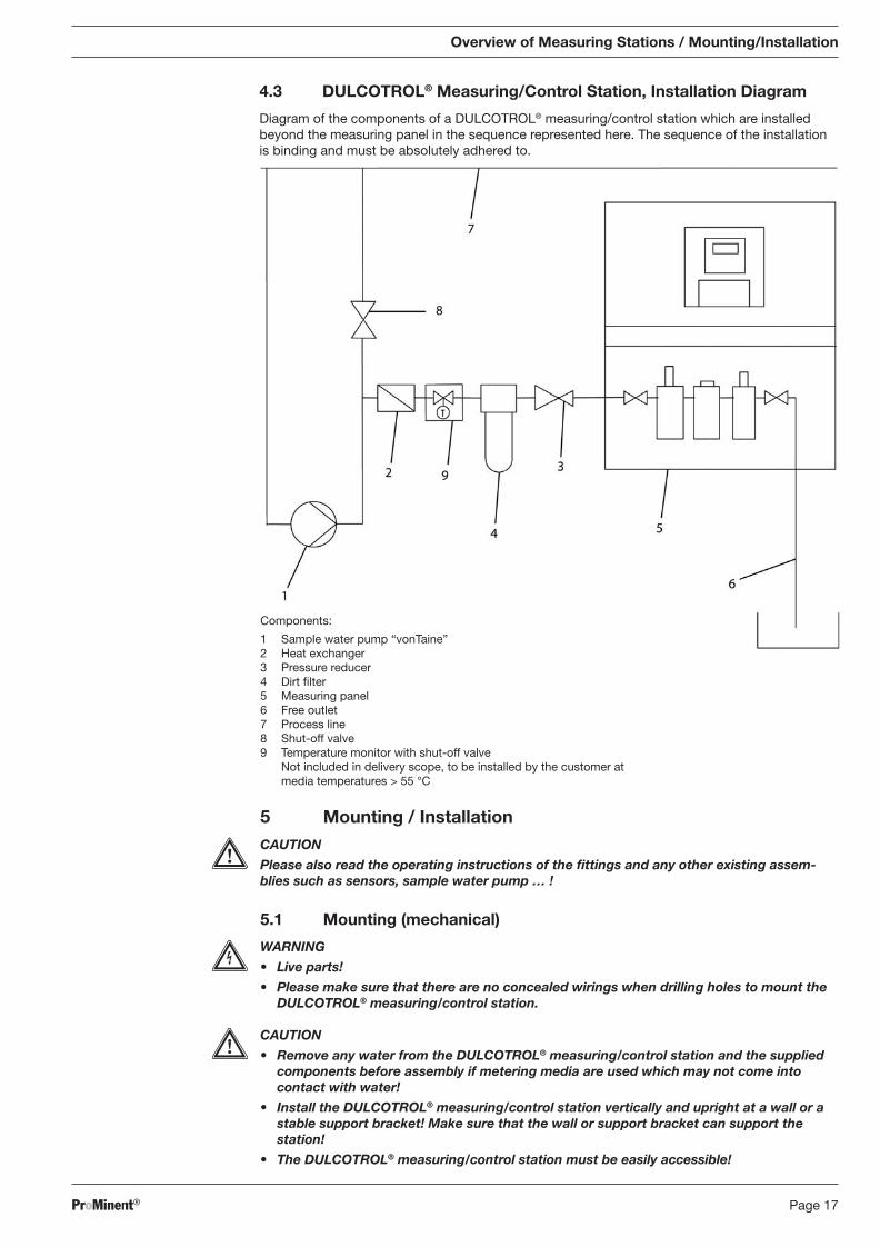
4.3 DULCOTROL® Measuring/Control Station, Installation Diagram
Diagram of the components of a DULCOTROL® measuring/control station which are installed beyond the measuring panel in the sequence represented here. The sequence of the installation is binding and must be absolutely adhered to.
5 Mounting / Installation CAUTION
Please also read the operating instructions of the fi ttings and any other existing assem-blies such as sensors, sample water pump … !
5.1 Mounting (mechanical)
WARNING
• Live parts!
• Please make sure that there are no concealed wirings when drilling holes to mount the DULCOTROL® measuring/control station.
CAUTION
• Remove any water from the DULCOTROL® measuring/control station and the supplied components before assembly if metering media are used which may not come into contact with water!
• Install the DULCOTROL® measuring/control station vertically and upright at a wall or a stable support bracket! Make sure that the wall or support bracket can support the station!
• The DULCOTROL® measuring/control station must be easily accessible!
Components:
1 Sample water pump “vonTaine” 2 Heat exchanger 3 Pressure reducer 4 Dirt fi lter 5 Measuring panel 6 Free outlet 7 Process line 8 Shut-off valve 9 Temperature monitor with shut-off valve
Not included in delivery scope, to be installed by the customer at media temperatures > 55 °C
BA_DR_001_02_09_GB.indd 17BA_DR_001_02_09_GB.indd 17 24.02.2009 12:24:00 Uhr24.02.2009 12:24:00 Uhr
ProMinent®Page 18
CAUTION
• Metering media may be metered in excess.
• If the fl oat of the fl ow module gets stuck because of contaminations, the DULCOTROL® measuring/control station may meter in excess!
• Install a fi lter, depending on the type and composition of the sample water.
• If the circulating pump does not deliver, the DULCOTROL® measuring/control station may meter in excess!
• Interlock the control via the potential-free contact of the circulating pump. If the cir cu-lat ing pump is “OFF”, the DULCOTROL® measuring/control station goes to “PAUSE” via the pause input of the controller.
• Alternatively, the metering pumps can be switched such that they only work together with the circulating pumps.
5.1.1 Measuring Station
The mounting height should be selected such that:
• the LCD panel of the control is well readable
• the cover of the controller can still be parked in “park position” (145 mm)
• there is still enough space below the in-line probe to carry out maintenance work (100 mm)
• there is enough space for the mounting of accessories beyond the panel
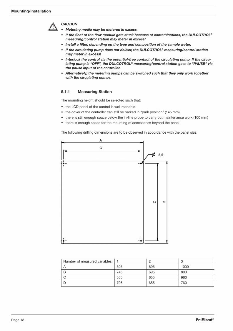
The following drilling dimensions are to be observed in accordance with the panel size:
Mounting/Installation
Number of measured variables 1 2 3
A 595 695 1000
B 745 695 800
C 555 655 960
D 705 655 760
BA_DR_001_02_09_GB.indd 18BA_DR_001_02_09_GB.indd 18 24.02.2009 12:24:00 Uhr24.02.2009 12:24:00 Uhr
ProMinent® Page 19
Mounting/Installation
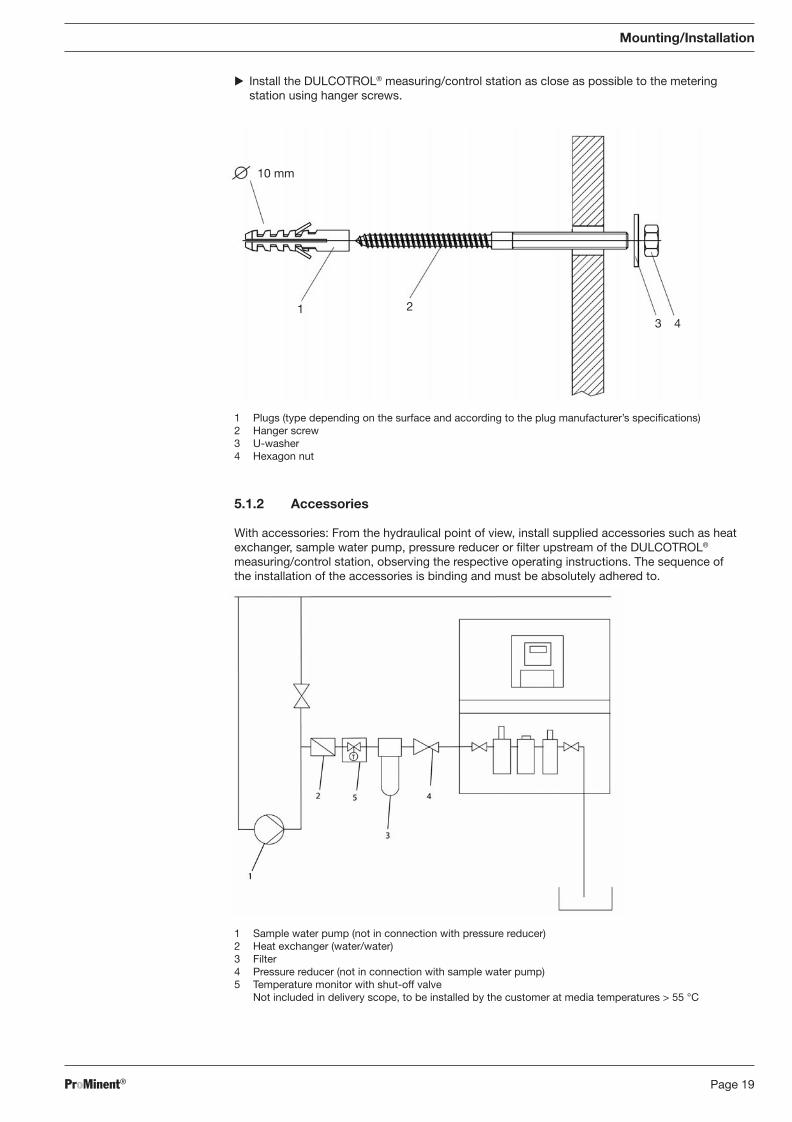
� Install the DULCOTROL® measuring/control station as close as possible to the metering station using hanger screws.
5.1.2 Accessories
With accessories: From the hydraulical point of view, install supplied accessories such as heat exchanger, sample water pump, pressure reducer or fi lter upstream of the DULCOTROL® meas ur ing/control station, observing the respective operating instructions. The sequence of the installation of the accessories is binding and must be absolutely adhered to.
1 Plugs (type depending on the surface and according to the plug manufacturer’s specifi cations) 2 Hanger screw 3 U-washer 4 Hexagon nut
10 mm
1 23 4
1 Sample water pump (not in connection with pressure reducer) 2 Heat exchanger (water/water) 3 Filter 4 Pressure reducer (not in connection with sample water pump) 5 Temperature monitor with shut-off valve
Not included in delivery scope, to be installed by the customer at media temperatures > 55 °C
BA_DR_001_02_09_GB.indd 19BA_DR_001_02_09_GB.indd 19 24.02.2009 12:24:00 Uhr24.02.2009 12:24:00 Uhr
ProMinent®Page 20
5.2 Installation (hydraulic)
CAUTION
• Observe the maximum permissible operating parameters of the entire installation of the DULCOTROL® measuring/control station (e.g. pressure, temperature, fl ow rate)!
• Observe the lowest maximum permissible operating parameters of the component parts of the DULCOTROL® measuring/control station and the installed sensors (and their operating instructions)!
• Please also read the operating instructions of the controllers and fi ttings and any other existing assemblies such as sensors, sample water pump … !
• Ensure a correct fl ow direction of the sample water.
• The maximum operating pressure (1 bar) may not be exceeded.
• A pressure reducer must be installed.
• Hazards from media under pressure.
• Before starting work at the hydraulical part of the DULCOTROL® measuring/control station, this part is to be depressurised in a controlled way using the sampling valve.
• Wear safety goggles.
Fittings
The bypass fi tting (in-line probe) used depends in particular on the sample water, sometimes also on the measured variable or the combination of the measured variables. For all clear waters, the type DGMA with fl ow monitoring, and for contaminated waters, DLG III also with upstream fl ow monitoring are always used. The DGMA bypass fi tting always includes in addition to the required measuring modules an additional measuring module for refi tting a correction variable.
Hydraulic Connection, Piping
The hydraulic connection of the sample water is made via a 8x5mm hose connection. Shut-off ball valves are installed upstream and downstream of the bypass fi tting. Upstream of the bypass fi tting, the optionally available sample water fi lter will be positioned. The bypass fi ttings include a sampling valve. For an equipotential bonding circuit, a metal pin is integrated in the bypass fi ttings (see operating instructions DULCOMETER® D1C, Part 1).
5.2.1 DULCOTROL® Measuring/Control Station
� Connect the in-line probe or fi tting to the sample water (see operating instructions of the in-line probe or documentation of the fi tting).
5.3 Installation of DULCOTROL® Measuring/Control Station (electrical)
WARNING
• Live parts!
• Disconnect from mains plug before opening the housing.
• De-energise damaged, defective or manipulated units by disconnecting the mains plug.
• The electrical installation of the electrical assemblies may only be performed by a qualifi ed electrician!
• The controller may only be opened by a qualifi ed electrician!
• With only one controller: Install a mains switch to be able to quickly disconnect from the mains supply in case of emergency! For stations with two or more controllers, the switch is installed at the terminal box.
CAUTION
• Please also read the operating instructions of the controllers and fi ttings and any other existing assemblies such as sensors, sample water pump … !
Mounting/Installation
BA_DR_001_02_09_GB.indd 20BA_DR_001_02_09_GB.indd 20 24.02.2009 12:24:00 Uhr24.02.2009 12:24:00 Uhr
ProMinent® Page 21
Mounting/Installation
5.3.1 Measuring Panel
� Install a mains cable at the terminal box or at the controller in case of only one controller.
� Electrically install the fl ow meter (cables are pre-installed at the controller).
5.3.2 Sample Water Pump
� With terminal box: Connect the sample water pump to the terminal box in accordance with the terminal diagram.
� Without terminal box: Connect the sample water pump to the supply voltage as described in its operating instructions.
5.4 Mounting of the Sensors
Depending on the Identcode (Identcode feature “Sensor assembly”), some sensors will be delivered already installed in the fi tting. If no sensors are installed, the holes in the fi tting are tightly sealed. The following sensors are not delivered as installed because of their sensitivity but enclosed in the original packaging of the DULCOTROL® measuring/control station.
• All pH/ORP sensors
• All amperometric sensors
• The oxygen sensor DO 1 will be installed, the sensor module will be separately enclosed.
The sensors for oxygen, conductivity, and temperature are pre-installed.
Before installing the sensors, the respective blanking plugs are to be removed from the DULCOTROL® measuring/control station and the respective sensors are then to be installed. The installation of the sensors is described in the respective chapter for the measured variable.
5.5 Hydraulic Test Run after Installation
Having completed the installation, a hydraulic test run of the DULCOTROL® measuring/control station is to be performed.
• The sampling valve must be closed! Otherwise, sample water may leak!
• Check all screw fi ttings before the fi rst commissioning!
• Open the shut-off ball valve on the inlet and outlet side.
• The station must be hydraulically leak-proof. No liquids may escape.
Should liquid escape, the cause is to be identifi ed and remedied.
BA_DR_001_02_09_GB.indd 21BA_DR_001_02_09_GB.indd 21 24.02.2009 12:24:00 Uhr24.02.2009 12:24:00 Uhr
ProMinent®Page 22
5.6 Installation of the Sensor (electrical)
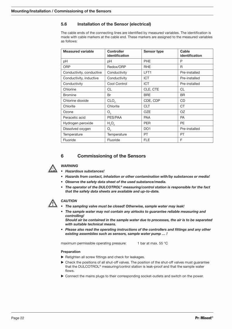
The cable ends of the connecting lines are identifi ed by measured variables. The identifi cation is made with cable markers at the cable end. These markers are assigned to the measured variables as follows:
6 Commissioning of the Sensors
WARNING
• Hazardous substances!
• Hazards from contact, inhalation or other contamination with/by substances or media!
• Observe the safety data sheet of the used substance/media.
• The operator of the DULCOTROL® measuring/control station is responsible for the fact that the safety data sheets are available and up-to-date.
CAUTION
• The sampling valve must be closed! Otherwise, sample water may leak!
• The sample water may not contain any airlocks to guarantee reliable measuring and controlling! Should air be contained in the sample water due to processes, the air is to be separated with suitable technical means.
• Please also read the operating instructions of the controllers and fi ttings and any other existing assemblies such as sensors, sample water pump … !
maximum permissible operating pressure: 1 bar at max. 55 °C
Preparation
� Retighten all screw fi ttings and check for leakages.
� Check the positions of all shut-off valves. The position of the shut-off valves must guarantee that the DULCOTROL® measuring/control station is leak-proof and that the sample water fl ows.
� Connect the mains plugs to their corresponding socket-outlets and switch on the power.
Mounting/Installation / Commissioning of the Sensors
Measured variable Controller Sensor type Cable identifi cation identifi cation
pH pH PHE P
ORP Redox/ORP RHE R
Conductivity, conductive Conductivity LFT1 Pre-installed
Conductivity, inductive Conductivity ICT Pre-installed
Conductivity Cool Control ICT Pre-installed
Chlorine CL CLE, CTE CL
Bromine Br BRE BR
Chlorine dioxide CLO2 CDE, CDP CD
Chlorite Chlorite CLT CT
Ozone O3 OZE OZ
Peracetic acid PES/PAA PAA PA
Hydrogen peroxide H2O2 PER PE
Dissolved oxygen O2 DO1 Pre-installed
Temperature Temperature PT PT
Fluoride Fluoride FLE F
BA_DR_001_02_09_GB.indd 22BA_DR_001_02_09_GB.indd 22 24.02.2009 12:24:00 Uhr24.02.2009 12:24:00 Uhr
ProMinent® Page 23
Commissioning of the Sensors
6.1 Setting of the Flow Meter Switching Point
� Reduce the fl ow rate for the test - the alarm device must engage.
� Check the screw fi tting for leakages.
For in-line probe DLG III and DGMa:
Objective: Flow rate reduction is to switch – “Pause” at controller given closed input
� Set the fl ow rate at the ball valve.
� Setting value: 40 l/h
� Test value: 30 to 60 l/h (read at the upper edge of the fl oat)
� Loosen the fl ow rate sensor.
� Move the fl ow rate sensor in the rail from the top to the bottom until the controller goes to “Pause”.
� Move the fl ow rate sensor to the top until “Pause” at the controller is just cancelled.
� Secure the fl ow rate sensor.
� Reduce the fl ow rate for the test - the controller must go to “Pause”.
6.2 Running-In Period
A running-in period is to be observed for all amperometric sensors. Depending on the sensor, this may vary between 1 hour and 24 hours. The respective sensor, electrically connected, must be positioned in the sample water to be measured. This sample water must already contain the measured variable in the quality and quantity suffi cient for the process.
Running-in of the sensors is described in the respective chapter for the measured variable.
BA_DR_001_02_09_GB.indd 23BA_DR_001_02_09_GB.indd 23 24.02.2009 12:24:00 Uhr24.02.2009 12:24:00 Uhr
ProMinent®Page 24
Device Overview / Controls D1C / D2C General
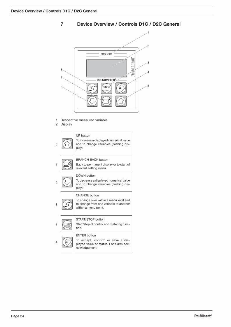
1 Respective measured variable 2 Display
®
DULCOMETER®
STOPSTART
2
3
4
5
8
6
7
1
XXXXXX
UP button
To increase a displayed numerical value and to change variables (fl ashing dis-play)
BRANCH BACK button
Back to permanent display or to start of relevant setting menu.
DOWN button
To decrease a displayed numerical value and to change variables (fl ashing dis-play).
CHANGE button
To change over within a menu level and to change from one variable to another within a menu point.
START/STOP button
Start/stop of control and metering func-tion.
ENTER button
To accept, confirm or save a dis-played value or status. For alarm ack-nowledgement.
5
7
6
STOPSTART
8
3
4
7 Device Overview / Controls D1C / D2C General
BA_DR_001_02_09_GB.indd 24BA_DR_001_02_09_GB.indd 24 24.02.2009 12:24:00 Uhr24.02.2009 12:24:00 Uhr
ProMinent® Page 25
Description Comment Symbol
Limit value transgression Symbol Relay 1, upper left
Symbol Relay 1, lower left
Symbol Relay 2, upper right
Symbol Relay 2, lower right
Metering pump 1 (chlorine) Symbol Control off left
Symbol Control on left
Metering pump 2 (dechlorine) Symbol Control off right
Symbol Control on right
Solenoid valve 1 (chlorine) Symbol Control off left
Symbol Control on left
Solenoid valve 2 (dechlorine) Symbol Control off right
Symbol Control on right
Servomotor Control, open relay
Control, close relay
Without control
Thickness of bar Position feedback increases from left to right during opening
Stop button pressed
Manual metering
Fault
Free Chlorine
8 Measuring Parameters
8.1 Measuring Parameter Free Chlorine
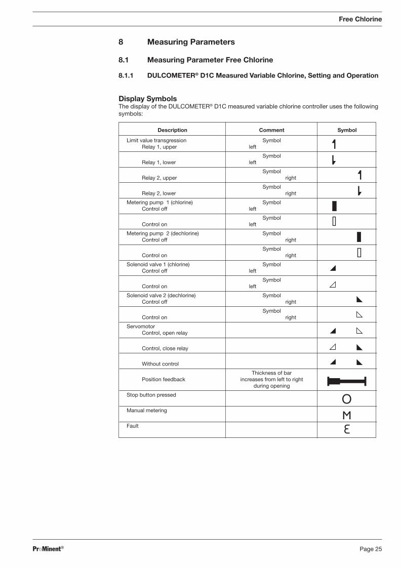
8.1.1 DULCOMETER® D1C Measured Variable Chlorine, Setting and Operation
Display Symbols The display of the DULCOMETER® D1C measured variable chlorine controller uses the following
symbols:
BA_DR_001_02_09_GB.indd 25BA_DR_001_02_09_GB.indd 25 24.02.2009 12:24:01 Uhr24.02.2009 12:24:01 Uhr
ProMinent®Page 26
Operation
Free Chlorine
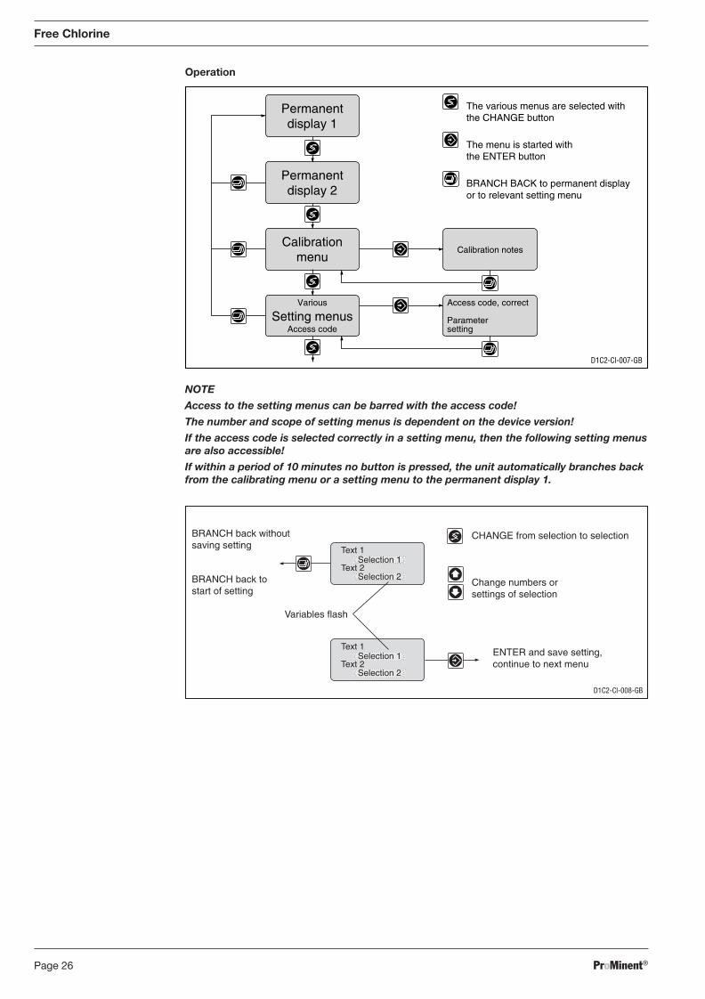
NOTE
Access to the setting menus can be barred with the access code!
The number and scope of setting menus is dependent on the device version!
If the access code is selected correctly in a setting menu, then the following setting menus are also accessible!
If within a period of 10 minutes no button is pressed, the unit automatically branches back from the calibrating menu or a setting menu to the permanent display 1.
D1C2-Cl-008-GB
CHANGE from selection to selection
Change numbers orsettings of selection
Variables flash
ENTER and save setting,continue to next menu
BRANCH back withoutsaving setting
BRANCH back tostart of setting
Text 1
Text 2Selection 1
Selection 2
Text 1
Text 2Selection 1
Selection 2
Access code, correct
Parametersetting
Calibration notes
Permanentdisplay 1
Permanentdisplay 2
Calibrationmenu
Various
Access codeSetting menus
D1C2-Cl-007-GB
The various menus are selected withthe CHANGE button
The menu is started withthe ENTER button
BRANCH BACK to permanent displayor to relevant setting menu
BA_DR_001_02_09_GB.indd 26BA_DR_001_02_09_GB.indd 26 24.02.2009 12:24:01 Uhr24.02.2009 12:24:01 Uhr
ProMinent® Page 27
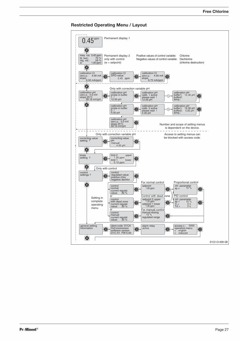
Restricted Operating Menu / Layout
Free Chlorine
33.0°C 33.0°C
calibration pHprobe in buffer2 !4.00 pH
calibration pHcalib. 2 activeplease wait !4.00 pH
calibration pHbuffer1:buffer2:temp.:
12.30 pH
Only with correction variable pHcorrecting valuesetting ?
correcting valuepH
limit 21.50 ppm
upperlimitssetting ?
Control with dead zone
For normal control
PID control
Proportional controlsetpoint
1.00 ppm
setpoint 2 upper ctrl. parameter
Ti =Td =
xp =setpoint 1 lower
10 %
ctrl. parameterxp = 10 %
controlsettings ?
Only with controlcontrol
positive chlorregulated value:
negative dechlor
manual dosing
control
current regulat.value: 30 %
normal
15 %regulated range
general settinginformation
ident-code: D1CA
software versionDxCxxxxxxxxxx
D1C-A1 FW-5.00
alarm relay access c.:
==
operating menu:active5000
english
1.20 ppm
1.00 ppm
calibration pHzero p.:slope 25°C
0.0 mV
59.16 mV/pH
control
current regulat.value: 30 %
with dead zone
control
current regulat.value: 30 %
manual
Setting incompleteoperatingmenu
or
or For manual control
reduced
4.00 pH
4.50 pH
limit 10.10 ppm
lower
Permanent display 1
Permanent display 2only with control(w = setpoint)
ppm0.45
calibration Cl calibration ClDPD-value:
0.45
mea. val.fd. fwd.:reg. val.:
0.45 ppm
w: 1.00 ppm
ppm
70 %59 %
zero p.:slope:
4.00 mA
6.50 mA/ppm
Positive values of control variable:Negative values of control variable:
calibration Clzero p.:slope:
4.00 mA
6.75 mA/ppm
ChlorineDechlorine(chlorine destruction)
Only with correction variable pH
33.0°C 33.0°C
calibration pHzero p.:slope 25°C
0.0 mV
59.16 mV/pH
calibration pHprobe in buffer1 !12.00 pH
calibration pHcalib. 1 activeplease wait !12.00 pH
calibration pHbuffer1:buffer2:temp.:
12.30 pH
manual
0 s0 s
Number and scope of setting menusis dependent on the device.
Access to setting menus canbe blocked with access code.
D1C2-Cl-009-GB
BA_DR_001_02_09_GB.indd 27BA_DR_001_02_09_GB.indd 27 24.02.2009 12:24:01 Uhr24.02.2009 12:24:01 Uhr
ProMinent®Page 28
8.1.2 DULCOTEST® CLE Chlorine Sensor for Free Chlorine, Commissioning
8.1.2.1 DULCOTEST® CLE Chlorine Sensor for Free Chlorine, Assembly
Assembly
Pouring electrolyte
IMPORTANT
• Do not touch, damage or bring into contact with greasy substances the white mem-brane or the electrodes on the electrode shaft. The sensor will not, in such cases, work accurately.
• Replace the membrane cap or send the sensor to ProMinent to have the electrodes cleaned.
NOTE
Carry out the following actions over a washbasin.
� Remove the red cap completely from the nozzle and cut the nozzle at the marked position to open the nozzle canal.
� Remove the membrane cap cover and unscrew the membrane cap from the electrode shaft.
� Rinse the membrane cap and the electrode with a little electrolyte.
� Fill the membrane cap up to the rim with electrolyte.
� Remove air bubbles by lightly tapping the membrane cap on an even surface.
Assembling membrane cap � Place the electrode shaft upright onto the fi lled membrane cap and twist until the thread bites.
� Rotate the electrode shaft until the vent hole is pointing upwards.
� Slowly screw in the membrane cap by hand up to the stop. Excess electrolyte will seep out of the vent hole as you screw the parts together.
� Rinse away the excess electrolyte from your fi ngers and from the sensor under running water.
� There should be no air left in the membrane cap/electrolyte. Repeat the above steps if there is still air present.
Assembling sensor
IMPORTANT
� When removing and inserting the sensor from or into the in-line probe housing, do so slowly to prevent damaging the membrane.
� The sensor must be kept damp after commissioning, e.g. the in-line probe housing should never be allowed to run dry.
Assemble the sensor as described in the operating instructions manual for the in-line probe housing.
8.1.2.2 DULCOTEST® CLE Chlorine Sensor for Free Chlorine, Electrical Installation
IMPORTANT
Do not switch the measuring system off when using intermittently. If necessary, use a timer to switch on metering equipment.
When connecting to a ProMinent® device Safety conditions at the interface are automatically fulfi lled when connecting to ProMinent®
controllers (e.g. DULCOMETER® D1C, DMT, CLD).
The CLE 3-mA is a sensor with a passive 4-20 A two-wire interface, i.e. the power supply is external, e.g. via the controller.
Free Chlorine
BA_DR_001_02_09_GB.indd 28BA_DR_001_02_09_GB.indd 28 24.02.2009 12:24:01 Uhr24.02.2009 12:24:01 Uhr
ProMinent® Page 29
Free Chlorine
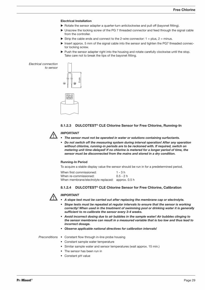
Electrical Installation
� Rotate the sensor adapter a quarter-turn anticlockwise and pull off (bayonet fi tting).
� Unscrew the locking screw of the PG 7 threaded connector and feed through the signal cable from the controller.
� Strip the cable ends and connect to the 2-wire connector: 1 = plus, 2 = minus.
� Insert approx. 5 mm of the signal cable into the sensor and tighten the PG7 threaded connec-tor locking screw.
� Push the sensor adapter right into the housing and rotate carefully clockwise until the stop. Take care not to break the tips of the bayonet fi tting.
Electrical connection to sensor
1 2
5 cm
8.1.2.3 DULCOTEST® CLE Chlorine Sensor for Free Chlorine, Running-In
IMPORTANT
• The sensor must not be operated in water or solutions containing surfactants.
• Do not switch off the measuring system during interval operation! After any operation without chlorine, running-in periods are to be reckoned with. If required, switch on metering unit time-delayed! If no chlorine is metered for a longer period of time, the sensor must be disconnected from the mains and stored in a dry condition.
Running-In Period
To acquire a stable display value the sensor should be run in for a predetermined period.
When fi rst commissioned: 1 - 3 h When re-commissioned: 0.5 - 2 h When membrane/electrolyte replaced: approx. 0.5 h
8.1.2.4 DULCOTEST® CLE Chlorine Sensor for Free Chlorine, Calibration
IMPORTANT
• A slope test must be carried out after replacing the membrane cap or electrolyte.
• Slope tests must be repeated at regular intervals to ensure that the sensor is working correctly! When used in the treatment of swimming pool or drinking water it is generally suffi cient to re-calibrate the sensor every 3-4 weeks.
• Avoid incorrect dosing due to air bubbles in the sample water! Air bubbles clinging to the sensor membrane can result in a measured variable that is too low and thus lead to incorrect dosage.
• Observe applicable national directives for calibration intervals!
Preconditions • Constant fl ow through in-line probe housing
• Constant sample water temperature
• Similar sample water and sensor temperatures (wait approx. 15 min.)
• The sensor has been run in
• Constant pH value
BA_DR_001_02_09_GB.indd 29BA_DR_001_02_09_GB.indd 29 24.02.2009 12:24:01 Uhr24.02.2009 12:24:01 Uhr
ProMinent®Page 30
Free Chlorine
Zero Point Calibration
If a ProMinent controller is being used to operate the sensor, zero point calibration is not usually necessary. Zero point calibration should be carried out, however, if operating the sensor at the lower measurement threshold or when using the 0.5 ppm variant.
� Immerse the sensor in a container of clean, chlorine-free tap water.
� Stir with the sensor until the measured variable displayed at the controller has remained stable for 5 min.
� Calibrate the controller to zero in accordance with the operating instructions.
� Reinstall the sensor in the in-line probe housing (DGM; DLG) as described in ”Installation”.
Slope Test
� Determine the chlorine content in the sample water using an appropriate measurement system (e.g. DPD 1).
� Set the resulting value at the controller in accordance with the operating instructions.
Repeat calibration after 1 day!
Possible values
Initial value Increment Lower value Upper value Remarks
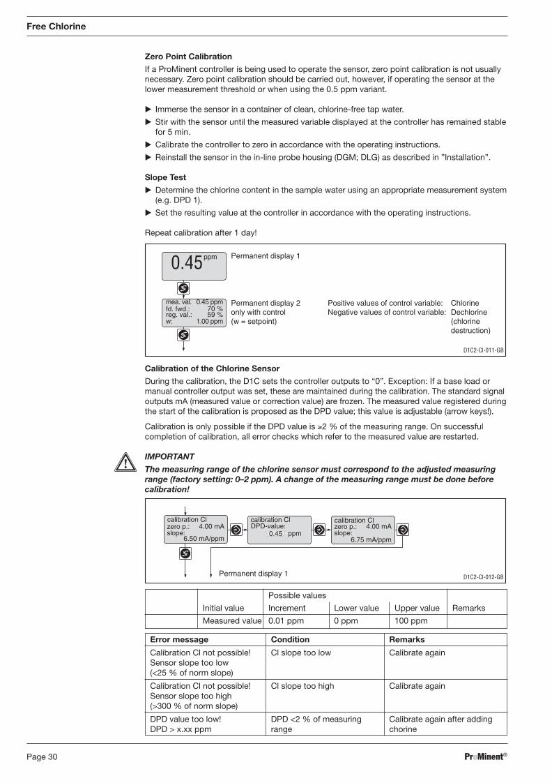
Measured value 0.01 ppm 0 ppm 100 ppm
Error message Condition Remarks
Calibration Cl not possible! Cl slope too low Calibrate again Sensor slope too low (<25 % of norm slope)
Calibration Cl not possible! Cl slope too high Calibrate again Sensor slope too high (>300 % of norm slope)
DPD value too low! DPD <2 % of measuring Calibrate again after adding DPD > x.xx ppm range chorine
Calibration of the Chlorine Sensor
During the calibration, the D1C sets the controller outputs to “0”. Exception: If a base load or manual controller output was set, these are maintained during the calibration. The standard signal outputs mA (measured value or correction value) are frozen. The measured value registered during the start of the calibration is proposed as the DPD value; this value is adjustable (arrow keys!).
Calibration is only possible if the DPD value is ≥2 % of the measuring range. On successful completion of calibration, all error checks which refer to the measured value are restarted.
IMPORTANT
The measuring range of the chlorine sensor must correspond to the adjusted measuring range (factory setting: 0–2 ppm). A change of the measuring range must be done before calibration!
D1C2-Cl-011-GB
Permanent display 1
Permanent display 2only with control(w = setpoint)
ppm0.45
mea. val.fd. fwd.:reg. val.:
0.45 ppm
w: 1.00 ppm
70 %59 %
Positive values of control variable: ChlorineNegative values of control variable: Dechlorine
(chlorinedestruction)
D1C2-Cl-012-GB
calibration Cl calibration ClDPD-value:
0.45 ppmzero p.:slope:
4.00 mA
6.50 mA/ppm
calibration Clzero p.:slope:
4.00 mA
6.75 mA/ppm
Permanent display 1
BA_DR_001_02_09_GB.indd 30BA_DR_001_02_09_GB.indd 30 24.02.2009 12:24:01 Uhr24.02.2009 12:24:01 Uhr
ProMinent® Page 31
Free Chlorine
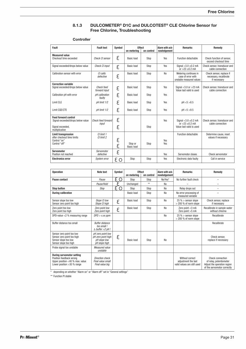
8.1.3 DULCOMETER® D1C and DULCOTEST® CLE Chlorine Sensor for Free Chlorine, Troubleshooting
Controller
Operation Note text Symbol Effect Alarm with ack- Remarks Remedy on metering on control nowledgement
Pause contact Pause Stop Stop No/Yes* No further fault check –
Pause/Hold Unchanged ** No – –
Stop button Stop Stop Stop No Relay drops out –
During calibration Basic load Stop No No error processing of – measured variable
Sensor slope too low Slope Cl low Basic load Stop No 25 % > sensor slope Check sensor, replace Sensor zero point too high Slope Cl high > 200 % of norm slope if necessary
Zero point too low Zero point low Basic load Stop No Zero point <3 mA Recalibrate in sample water Zero point too high Zero point high Zero point >5 mA without chlorine
DPD-value <2 % measuring range DPD > x.xx ppm No 25 % > sensor slope Recalibrate > 200 % of norm slope
Buffer distance too small Buffer distance Recalibrate too small ! Δ buffer >2 pH !
Sensor zero point too low pH zero point low Sensor zero point too high pH zero point high Check sensor, Sensor slope too low pH slope low Basic load Stop No replace if necessary Sensor slope too high pH slope high
Probe signal too unstable Measured value unstable
During servomotor setting Position feedback wrong Direction check Without correct Check connection Upper position <40 % max. value Final value small adjustment the last of relay, potentiometer Lower position >30 % range Final value big valid values are still used Adjust the operation region of the servomotor correctly
* depending on whether “Alarm on” or “Alarm off” set in “General settings”
** Function PI stable
Fault Fault text Symbol Effect Alarm with ack- Remarks Remedy on metering on control nowledgement
Measured value Checkout time exceeded Check Cl sensor Basic load Stop Yes Function detachable Check function of sensor, exceed checkout time
Signal exceeded/drops below value Check Cl input Basic load Stop Yes Signal <3.0 ±0.2 mA Check sensor, transducer and or >23 ±0.2 mA cable connection
Calibration sensor with error Cl calib. Basic load Stop No Metering continues in Check sensor, replace if defective case of error with necessary, recalibrate unstable measured values if necessary
Correction variable Signal exceeded/drops below value Check feed Basic load Stop Yes Signal <3.0 or >23 mA Check sensor, transducer and forward input Value last valid is used cable connection
Calibration pH with error pH calibration Basic load Stop Yes faulty
Limit CLE pH limit 1/2 Basic load Stop Yes pH <5 >8.5
Limit CGE/CTE pH limit 1/2 Basic load Stop Yes pH <5 >9.5
Feed forward control Signal exceeded/drops below value Check feed forward Yes Signal <3.8 ±0.2 mA Check sensor, transducer and input or >23 ±0.2 mA cable connection Signal exceeded, Stop Value last valid is used multiplicative
Limit transgression Cl limit 1 Function detachable Determine cause, reset after checkout time limits Cl limit 2 values if necessary Control “on” Yes Control “off” Stop or Stop Yes Basic load
Servomotor Servomotor Position not reached defective Yes Servomotor closes Check servomotor
Electronics error System error Stop Stop Yes Electronic data faulty Call in service
BA_DR_001_02_09_GB.indd 31BA_DR_001_02_09_GB.indd 31 24.02.2009 12:24:01 Uhr24.02.2009 12:24:01 Uhr
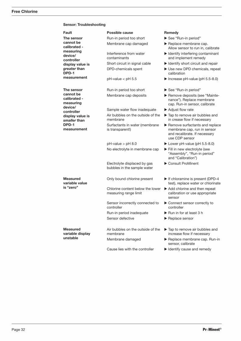
ProMinent®Page 32
Sensor: Troubleshooting
Free Chlorine
Fault
The sensor cannot be calibrated - measuring device/controller
display value is greater than
DPD-1
measurement
The sensor cannot be calibrated - measuring device/controller display value is smaller than DPD-1 measurement
Measured variable value is “zero”
Measured variable display unstable
Possible cause
Run-in period too short
Membrane cap damaged
Interference from water contaminants
Short circuit in signal cable
DPD-chemicals spent
pH-value < pH 5.5
Run-in period too short
Membrane cap deposits
Sample water fl ow inadequate
Air bubbles on the outside of the membrane
Surfactants in water (membrane is transparent!)
pH-value > pH 8.0
No electrolyte in membrane cap
Electrolyte displaced by gas bubbles in the sample water
Only bound chlorine present
Chlorine content below the lower measuring range limit
Sensor incorrectly connected to controller
Run-in period inadequate
Sensor defective
Air bubbles on the outside of the membrane
Membrane damaged
Cause lies with the controller
Remedy
� See “Run-in period”
� Replace membrane cap. Allow sensor to run in, calibrate
� Identify interfering contaminant and implement remedy
� Identify short circuit and repair
� Use new DPD chemicals, repeat calibration
� Increase pH-value (pH 5.5-8.0)
� See “Run-in period”
� Remove deposits (see “Main te-nance”). Replace membrane cap. Run-in sensor, calibrate
� Adjust fl ow rate
� Tap to remove air bubbles and in crease fl ow if necessary
� Remove surfactants and replace membrane cap, run in sensor and recalibrate. If necessary use CDP sensor
� Lower pH-value (pH 5.5-8.0)
� Fill in new electrolyte (see “Assembly”, “Run-in period” and “Calibration”)
� Consult ProMinent
� If chloramine is present (DPD-4 test), replace water or chlorinate
� Add chlorine and then repeat calibration or use appropriate sensor
� Connect sensor correctly to controller
� Run in for at least 3 h
� Replace sensor
� Tap to remove air bubbles and increase fl ow if necessary
� Replace membrane cap. Run-in sensor, calibrate
� Identify cause and remedy
BA_DR_001_02_09_GB.indd 32BA_DR_001_02_09_GB.indd 32 24.02.2009 12:24:01 Uhr24.02.2009 12:24:01 Uhr
ProMinent® Page 33
Free Chlorine
Troubleshooting / Maintenance
Once you have tried everything, check whether the reference electrode is brownish grey at the tip of the electrode shaft. If it is silvery white it is spent and should be reconditioned by ProMinent.
8.1.4 DULCOMETER® D1C Measured Variable Chlorine and DULCOTEST® CLE Chlorine Sensor, Maintenance
Controller
The DULCOMETER® controller type D1C for the measured variable chlorine is maintenance-free.
Sensor
IMPORTANT
� The sensor must be regularly serviced in order to avoid exceeding dosage due to sensor failure!
� Observe applicable national directives for service intervals!
� Do not touch the sensors or bring into contact with substances containing grease.
Maintenance interval Daily/weekly depending upon application
Maintenance Work
� Check the sensor display value on the controller using an appropriate chlorine measuring system (e.g. DPD-1).
� If necessary recalibrate the sensor.
Cleaning the Membrane
If it is no longer possible to calibrate the sensor you can try to clean the membrane carefully.
Firstly disassemble the sensor. Observe the safety instructions.
Loose dirt clinging to the cap:
� Rinse the membrane under a gentle stream of cold tap water.
Removing deposits (scale, rust):
� Disassemble the membrane cap.
� Place the membrane cap in a bath of 5 % hydrochloric acid (e.g. overnight).
� Rinse the membrane cap under plenty of water.
You should now refi ll the sensor with electrolyte, run in and recalibrate.
Replacing the Membrane
If the sensor fails to calibrate even after cleaning the membrane, or if the membrane is damaged, you must replace the membrane cap.
BA_DR_001_02_09_GB.indd 33BA_DR_001_02_09_GB.indd 33 24.02.2009 12:24:01 Uhr24.02.2009 12:24:01 Uhr
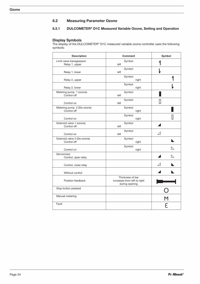
ProMinent®Page 34
8.2 Measuring Parameter Ozone
8.2.1 DULCOMETER® D1C Measured Variable Ozone, Setting and Operation
Display Symbols The display of the DULCOMETER® D1C measured variable ozone controller uses the following
symbols:
Ozone
Description Comment Symbol
Limit value transgression Symbol Relay 1, upper left
Symbol Relay 1, lower left
Symbol Relay 2, upper right
Symbol Relay 2, lower right
Metering pump 1 (ozone) Symbol Control off left
Symbol Control on left
Metering pump 2 (De-ozone) Symbol Control off right
Symbol Control on right
Solenoid valve 1 (ozone) Symbol Control off left
Symbol Control on left
Solenoid valve 2 (De-ozone) Symbol Control off right
Symbol Control on right
Servomotor Control, open relay
Control, close relay
Without control
Thickness of bar Position feedback increases from left to right during opening
Stop button pressed
Manual metering
Fault
BA_DR_001_02_09_GB.indd 34BA_DR_001_02_09_GB.indd 34 24.02.2009 12:24:01 Uhr24.02.2009 12:24:01 Uhr
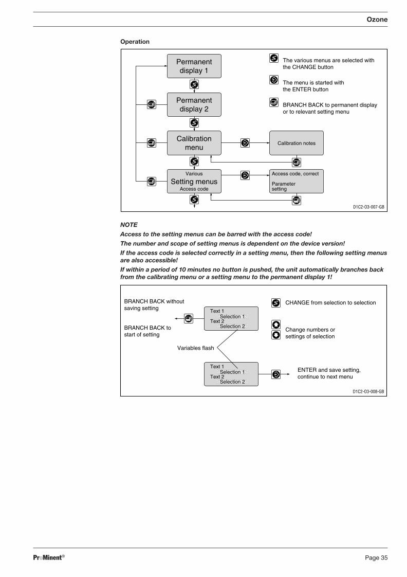
ProMinent® Page 35
NOTE
Access to the setting menus can be barred with the access code!
The number and scope of setting menus is dependent on the device version!
If the access code is selected correctly in a setting menu, then the following setting menus are also accessible!
If within a period of 10 minutes no button is pushed, the unit automatically branches back from the calibrating menu or a setting menu to the permanent display 1!
Ozone
D1C2-O3-008-GB
CHANGE from selection to selection
Change numbers orsettings of selection
Variables flash
ENTER and save setting,continue to next menu
BRANCH BACK withoutsaving setting
BRANCH BACK tostart of setting
Text 1
Text 2Selection 1
Selection 2
Text 1
Text 2Selection 1
Selection 2
Access code, correct
Parametersetting
Calibration notes
Permanentdisplay 1
Permanentdisplay 2
Calibrationmenu
Various
Access codeSetting menus
D1C2-O3-007-GB
The various menus are selected withthe CHANGE button
The menu is started withthe ENTER button
BRANCH BACK to permanent displayor to relevant setting menu
Operation
BA_DR_001_02_09_GB.indd 35BA_DR_001_02_09_GB.indd 35 24.02.2009 12:24:01 Uhr24.02.2009 12:24:01 Uhr
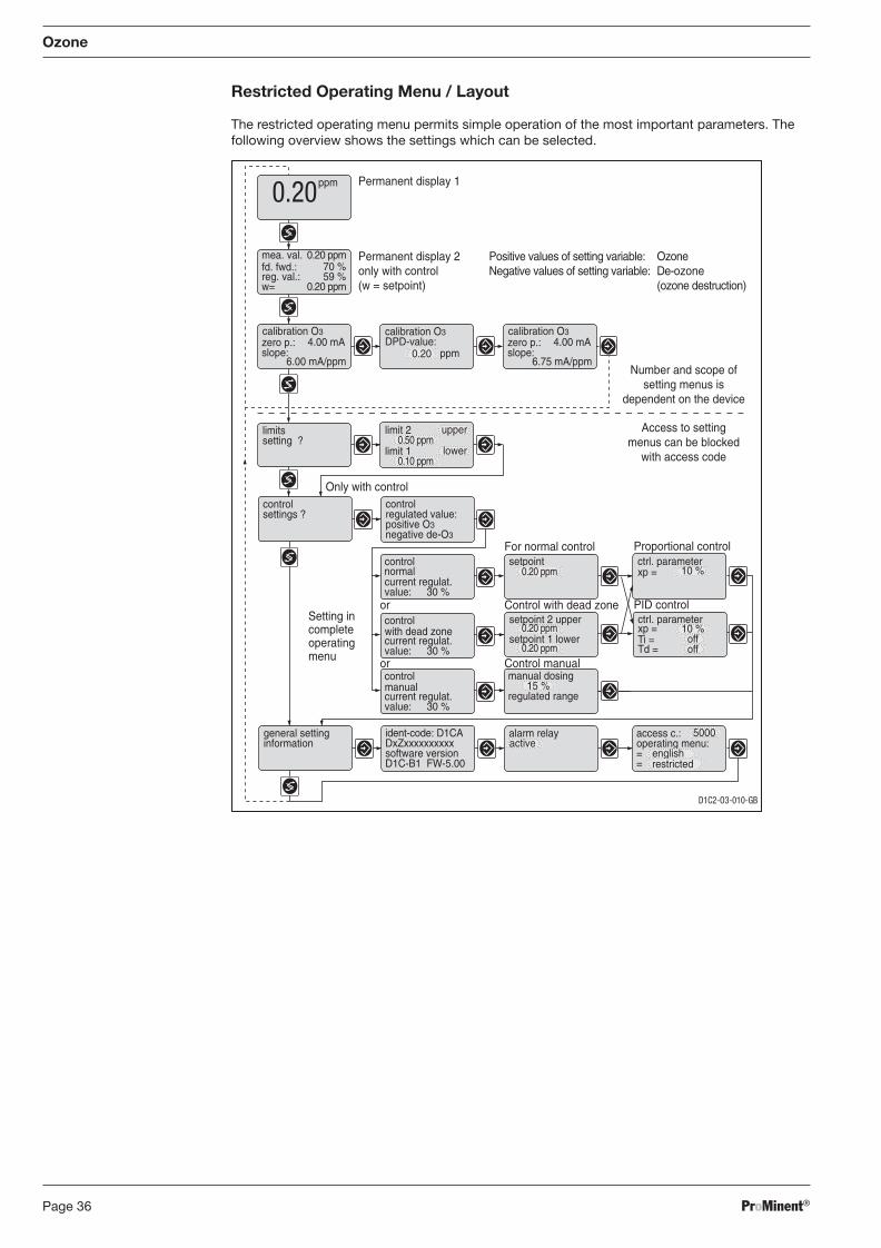
ProMinent®Page 36
Restricted Operating Menu / Layout
The restricted operating menu permits simple operation of the most important parameters. The following overview shows the settings which can be selected.
Ozone
control
current regulat.value: 30 %
with dead zone
control
current regulat.value: 30 %
manual
control
current regulat.value: 30 %
normal
D1C2-O3-010-GB
Permanent display 1
Permanent display 2only with control(w = setpoint)
ppm0.20
calibration O3 calibration O3DPD-value:
0.20
limitssetting ?
Control with dead zone
For normal control
PID control
Proportional controlsetpoint
0.20 ppm
setpoint 2 upper ctrl. parameter
Ti =Td =
xp =
offsetpoint 1 lower
10 %
ctrl. parameterxp = 10 %
controlsettings ?
Only with controlcontrol
positive O3regulated value:
negative de-O3
manual dosing 15 %
regulated range
general settinginformation
ident-code: D1CA
software versionDxZxxxxxxxxxx
D1C-B1 FW-5.00
alarm relay access c.:
==
operating menu:active5000
englishrestricted
mea. val.fd. fwd.:reg. val.:
0.20 ppm
w= 0.20 ppm
ppm
70 %59 %
zero p.:slope:
4.00 mA
6.00 mA/ppm
Positive values of setting variable:Negative values of setting variable:
OzoneDe-ozone(ozone destruction)
calibration O3zero p.:slope:
4.00 mA
6.75 mA/ppm
0.20 ppm
0.20 ppm
limit 2 upper0.50 ppm
limit 1 lower0.10 ppm
or
off
Control manualor
Setting incompleteoperatingmenu
Number and scope ofsetting menus is
dependent on the device
Access to settingmenus can be blocked
with access code
BA_DR_001_02_09_GB.indd 36BA_DR_001_02_09_GB.indd 36 24.02.2009 12:24:01 Uhr24.02.2009 12:24:01 Uhr
ProMinent® Page 37
Ozone
8.2.2 DULCOTEST® OZE Ozone Sensor, Commissioning
8.2.2.1 DULCOTEST® OZE Ozone Sensor for Ozone, Assembly
Assembly
Pouring electrolyte
CAUTION
• When handling ozone-containing water and solutions wear appropriate safety goggles and protective clothing!
• In case of eye contact with the electrolyte, rinse immediately with a lot of clean water for at least 10 min.! In case of eye irritation, contact an eye specialist!
• Do not swallow the electrolyte! Drink a lot of water. Trigger vomiting. Seek medical advice in case of indisposition!
• Protect yourself and your clothing against contact with the electrolyte (acid!) by suitable protective equipment!
• The skin might be chemically burnt or the clothing might be damaged! Rinse immediate-ly with a lot of cold water.
IMPORTANT
• Do not touch, damage or bring into contact with greasy substances the membrane at the bottom of the membrane cap and the electrodes at the bottom of the electrode shaft! The sensor will then no longer function accurately. Replace the membrane cap by a new one or return the sensor for cleaning of the electrodes.
• The electrolyte should not be kept in excess of 2 years! (For date of expiry, see label)
� Remove the red cap from the spout and cut the spout at the marked position to open the spout channel.
� Remove the protective membrane cover and unscrew the membrane cap from the electrode shaft.
� Rinse the membrane cap and the electrode with some of the electrolyte.
� Fill the membrane cap up to the brim with the electrolyte.
� Slightly tap the membrane cap onto an even surface to remove any air bubbles.
Assembling the membrane cap � Place the electrode shaft vertically on the fi lled membrane cap and turn until the thread is
locked.
� Turn the electrode shaft such that the vent hole is positioned to the top.
� Slowly screw in the membrane cap fi ngertight by hand up to the stop. The excessive electro-lyte fl ows out through the vent hole when screwing together the parts.
� Rinse the leaked electrolyte from the sensor and your fi ngers under running water.
� No air should be trapped in the membrane cap and the electrolyte. If air is trapped, repeat the above described steps.
Assembling sensor
IMPORTANT
• Depressurise the in-line probe before installing the sensor!
• Insert or remove the sensor only slowly into or from the in-line probe! Otherwise the membrane may be damaged!
• The membrane may not come into contact with the fl ow plug of the in-line probe!
• Ensure that the tensioning ring of the sensor is positioned within the in-line probe after installation! Otherwise, the sensor might be ejected from the in-line probe due to the water pressure.
• After commissioning, the sensor must always be kept wet – e.g. the in-line probe may never run dry!
� Install the sensor as described in the operating instructions of the in-line probe.
BA_DR_001_02_09_GB.indd 37BA_DR_001_02_09_GB.indd 37 24.02.2009 12:24:01 Uhr24.02.2009 12:24:01 Uhr
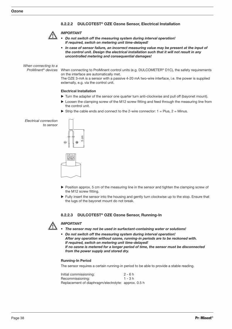
ProMinent®Page 38
Ozone
8.2.2.2 DULCOTEST® OZE Ozone Sensor, Electrical Installation
IMPORTANT
• Do not switch off the measuring system during interval operation! If required, switch on metering unit time-delayed!
• In case of sensor failure, an incorrect measuring value may be present at the input of the control unit. Design the electrical installation such that it will not result in any uncontrolled metering and consequential damages!
When connecting to a ProMinent® devices When connecting to ProMinent control units (e.g. DULCOMETER® D1C), the safety requirements
on the interface are automatically met. The OZE 3-mA is a sensor with a passive 4-20 mA two-wire interface, i.e. the power is supplied externally, e.g. via the control unit.
Electrical Installation
� Turn the adapter of the sensor one quarter turn anti-clockwise and pull off (bayonet mount).
� Loosen the clamping screw of the M12 screw fi tting and feed through the measuring line from the control unit.
� Strip the cable ends and connect to the 2-wire connector: 1 = Plus, 2 = Minus.
Electrical connection to sensor
1 2
5 cm
� Position approx. 5 cm of the measuring line in the sensor and tighten the clamping screw of the M12 screw fi tting.
� Fully insert the sensor into the housing and gently turn clockwise up to the stop. Ensure that the lugs of the bayonet mount do not break.
8.2.2.3 DULCOTEST® OZE Ozone Sensor, Running-In
IMPORTANT
• The sensor may not be used in surfactant-containing water or solutions!
• Do not switch off the measuring system during interval operation! After any operation without ozone, running-in periods are to be reckoned with. If required, switch on metering unit time-delayed! If no ozone is metered for a longer period of time, the sensor must be disconnected from the power supply and stored dry.
Running-In Period
The sensor requires a certain running-in period to be able to provide a stable reading.
Initial commissioning: 2 - 6 h Recommissioning: 1 - 3 h Replacement of diaphragm/electrolyte: approx. 0.5 h
BA_DR_001_02_09_GB.indd 38BA_DR_001_02_09_GB.indd 38 24.02.2009 12:24:01 Uhr24.02.2009 12:24:01 Uhr
ProMinent® Page 39
Ozone
8.2.2.4 DULCOTEST® OZE Ozone Sensor, Calibration
After expiry of the running-in period, the sensor can be calibrated.
IMPORTANT
• A slope calibration must be carried out after having replaced a diaphragm cap or electrolyte!
• For a perfect functioning of the sensor, the slope calibration must be repeated in regular intervals! For swimming pools, a calibration of the sensor every 3-4 weeks is suffi cient.
• Avoid incorrect metering because of airlocks in the sample water! Air bubbles sticking to the diaphragm of the sensor might cause a low measuring value and thus might result in incorrect metering.
• Observe the valid national regulations for calibration intervals!
Preconditions • Constant fl ow at the in-line probe
• Operating pressure of max. 1 bar maintained
• Constant temperature of the sample water
• Identical temperatures of sample water and sensor (wait for approx. 15 min.)
• Constant pH value
Zero Point Calibration
If the sensor is operated at a ProMinent control unit, a zero point calibration is normally not required. Perform a zero point calibration if you use the sensor at the lower measuring range limit.
Preconditions • The sensor has been run-in
• Constant fl ow at the in-line probe
� Dip the sensor in a bucket with clean, ozone-free tap water.
� Stir with the sensor until the reading at the control unit has been stable for 5 min.
� Calibrate the control unit to zero according to its operating instructions.
� Reinstall the sensor into the in-line probe (DGM; DLG).
Slope Test
Determine the ozone content of the sample water using a suitable measuring tool (e.g. DPD 4). Set the determined value at the control unit according to the unit’s operating instructions.
Repeat the calibration the next day!
NOTE
Calibration at increased temperature
Because ozone is only physically solved in water, it quickly outgasses from the medium at increased temperatures (> 30 °C). The DPD measurement must thus be performed quickly. After sample-taking, the reagents should be added within 1 minute. In this case, the red dye is to be directly generated at the sampling site by adding reagents and then the measurement is to be performed in the laboratory as quickly as possible.
BA_DR_001_02_09_GB.indd 39BA_DR_001_02_09_GB.indd 39 24.02.2009 12:24:02 Uhr24.02.2009 12:24:02 Uhr
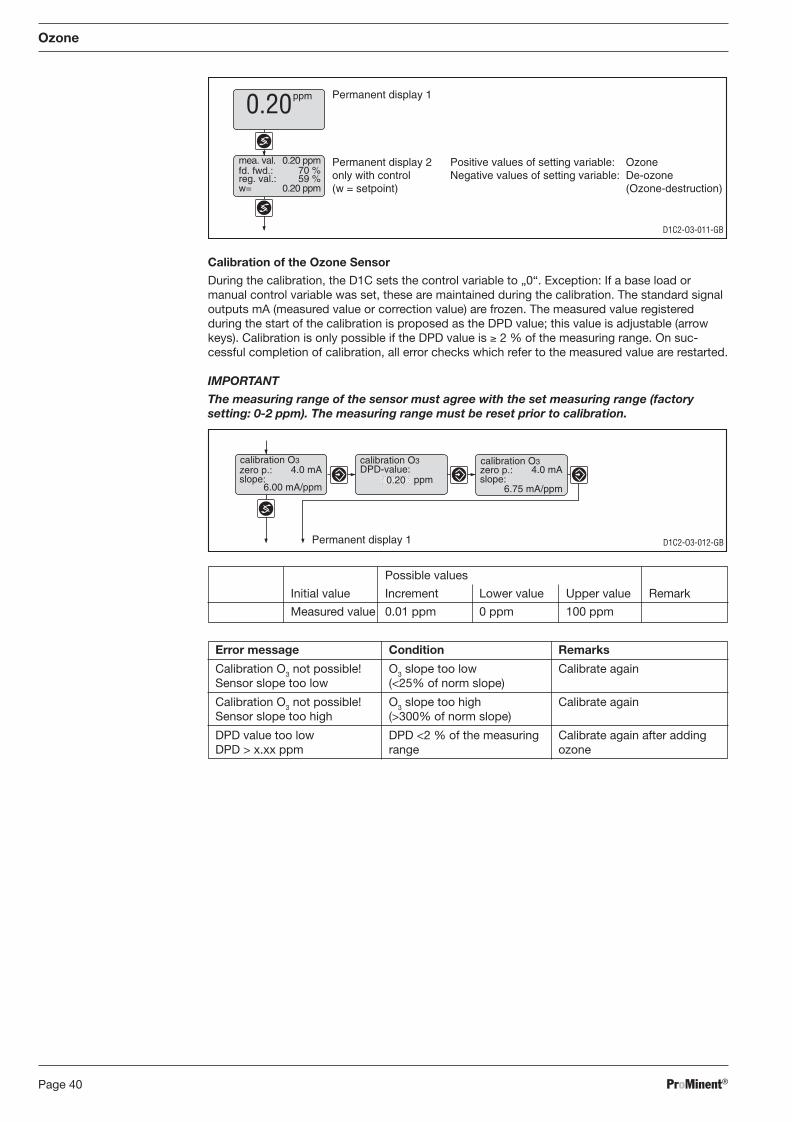
ProMinent®Page 40
Ozone
Calibration of the Ozone Sensor
During the calibration, the D1C sets the control variable to „0“. Exception: If a base load or manual control variable was set, these are maintained during the calibration. The standard signal outputs mA (measured value or correction value) are frozen. The measured value registered during the start of the calibration is proposed as the DPD value; this value is adjustable (arrow keys). Calibration is only possible if the DPD value is ≥ 2 % of the measuring range. On suc-cessful completion of calibration, all error checks which refer to the measured value are restarted.
IMPORTANT
The measuring range of the sensor must agree with the set measuring range (factory setting: 0-2 ppm). The measuring range must be reset prior to calibration.
Possible values
Initial value Increment Lower value Upper value Remark
Measured value 0.01 ppm 0 ppm 100 ppm
Error message Condition Remarks
Calibration O3 not possible! O3 slope too low Calibrate again Sensor slope too low (<25% of norm slope)
Calibration O3 not possible! O3 slope too high Calibrate again Sensor slope too high (>300% of norm slope)
DPD value too low DPD <2 % of the measuring Calibrate again after adding DPD > x.xx ppm range ozone
D1C2-O3-011-GB
Permanent display 1
Permanent display 2only with control(w = setpoint)
ppm0.20
mea. val.fd. fwd.:reg. val.:
0.20 ppm
w= 0.20 ppm
70 %59 %
Positive values of setting variable: OzoneNegative values of setting variable: De-ozone
(Ozone-destruction)
D1C2-O3-012-GB
calibration O3 calibration O3DPD-value:
0.20 ppmzero p.:slope:
4.0 mA
6.00 mA/ppm
calibration O3zero p.:slope:
4.0 mA
6.75 mA/ppm
Permanent display 1
BA_DR_001_02_09_GB.indd 40BA_DR_001_02_09_GB.indd 40 24.02.2009 12:24:02 Uhr24.02.2009 12:24:02 Uhr
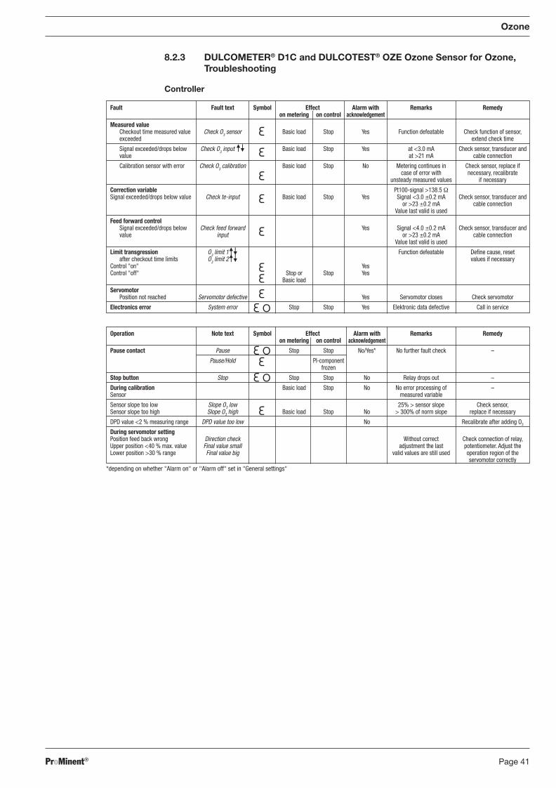
ProMinent® Page 41
Operation Note text Symbol Effect Alarm with Remarks Remedy on metering on control acknowledgement
Pause contact Pause Stop Stop No/Yes* No further fault check –
Pause/Hold PI-component frozen
Stop button Stop Stop Stop No Relay drops out –
During calibration Basic load Stop No No error processing of – Sensor measured variable
Sensor slope too low Slope O3 low 25% > sensor slope Check sensor, Sensor slope too high Slope O3 high Basic load Stop No > 300% of norm slope replace if necessary
DPD value <2 % measuring range DPD value too low No Recalibrate after adding O3
During servomotor setting Position feed back wrong Direction check Without correct Check connection of relay, Upper position <40 % max. value Final value small adjustment the last potentiometer. Adjust the Lower position >30 % range Final value big valid values are still used operation region of the servomotor correctly
8.2.3 DULCOMETER® D1C and DULCOTEST® OZE Ozone Sensor for Ozone, Troubleshooting
Controller
Ozone
*depending on whether "Alarm on" or "Alarm off" set in "General settings"
Fault Fault text Symbol Effect Alarm with Remarks Remedy on metering on control acknowledgement
Measured value Checkout time measured value Check O3 sensor Basic load Stop Yes Function defeatable Check function of sensor, exceeded extend check time
Signal exceeded/drops below Check O3 input Basic load Stop Yes at <3.0 mA Check sensor, transducer and value at >21 mA cable connection
Calibration sensor with error Check O3 calibration Basic load Stop No Metering continues in Check sensor, replace if case of error with necessary, recalibrate unsteady measured values if necessary
Correction variable Pt100-signal >138.5 Ω Signal exceeded/drops below value Check te-input Basic load Stop Yes Signal <3.0 ±0.2 mA Check sensor, transducer and or >23 ±0.2 mA cable connection Value last valid is used
Feed forward control Signal exceeded/drops below Check feed forward Yes Signal <4.0 ±0.2 mA Check sensor, transducer and value input or >23 ±0.2 mA cable connection Value last valid is used
Limit transgression O3 limit 1 Function defeatable Defi ne cause, reset
after checkout time limits O3 limit 2 values if necessary Control "on" Yes Control "off" Stop or Stop Yes Basic load
Servomotor Position not reached Servomotor defective Yes Servomotor closes Check servomotor
Electronics error System error Stop Stop Yes Elektronic data defective Call in service
BA_DR_001_02_09_GB.indd 41BA_DR_001_02_09_GB.indd 41 24.02.2009 12:24:02 Uhr24.02.2009 12:24:02 Uhr
ProMinent®Page 42
Sensor: Troubleshooting
For troubleshooting, the entire sensor is to be considered. The sensor consists of
1) Measuring/control unit 2) Electrical lines and connections 3) In-line probe and hydraulic connections 4) Sensor
The possible causes listed in the following table predominantly refer to the sensor. Before troubleshooting, ensure that the operating conditions are observed:
a) ozone content 0.02 - 2 mg/l b) pH value in the stability range ozone and constant c) temperature 5 - 45 °C and constant d) fl ow rate 30 - 60 l/h
For locating the failure in the measuring and control unit, the sensor simulator (DULCOMETER® Simulator order no. 1004042) can be used. A detailed troubleshooting at the measuring and control unit is described in the operating instructions of DULCOMETER® D1C, Ozone.
In case of excessive deviations of the sensor readings from the result of the DPD method, fi rst all possible error causes of the photometric DPD method should be considered. If required, the DPD measurement is to be repeated several times.
Ozone
Fault
Sensor cannot be calibrated - Reading measuring/control device greater than DPD-4 measurement
Sensor cannot be calibrated - Reading measuring/control device smaller than DPD-4 measurement
Possible cause
Running-in period too low
Diaphragm cap damaged
Interfering substances in water
Short in the measuring line
Distance between diaphragm and diaphragm cap too large
DPD chemicals past shelf life
Running-in period too low
Deposits on the diaphragm cap
Sample water fl ow rate too low
Air bubbles on the exterior of the diaphragm
Interfering substances in the sample water (surfactants, oils, alcohol, corrosion inhibitors)
Surfactants in water (diaphragm is transparent)
No electrolyte in diaphragm cap
Electrolyte displaced by gas bubbles in sample water
Remedy
� see “Running-in period”
� Replace diaphragm cap; run in sensor, calibrate
� Check water for interfering substances and remedy
� Locate short and remedy
� Tighten diaphragm cap up to stop
� Use new DPD chemicals, repeat calibration
� see “Running-in period”
� Remove deposits see “Mainte-nance”; replace diaphragm cap; run-in sensor, calibrate
� Adjust fl ow rate
� Remove air bubbles by tapping and increase fl ow rate, if required
� Contact ProMinent
� Remove surfactants and replace diaphragm cap; run-in sensor and calibrate
� Fill in new electrolyte see “Assembly”, “Running-in period” and “Calibration”)
� Contact ProMinent
BA_DR_001_02_09_GB.indd 42BA_DR_001_02_09_GB.indd 42 24.02.2009 12:24:02 Uhr24.02.2009 12:24:02 Uhr
ProMinent® Page 43
Ozone
* If the reference electrode is of a silvery bright or white colour, it must be regenerated. Brownish-grey or yellow-green discolourations, however, are common.
** The DULCOMETER® D1C can be used to display the sensor current for a sensor which is electrically connected. Please read the value in the fi eld “Zero point” in the complete operating menu, see operating instructions DULCOMETER® D1C, Ozone, Chapter 8 in the setting menu “Calibration ozone”. Do not confi rm by pressing the Enter key but exit the menu by pressing the Return key.
8.2.4 DULCOMETER® D1C Measured Variable Ozon and DULCOTEST® OZE Ozone Sensor for Ozone, Maintenance
Controller
The DULCOMETER® controller type D1C for the measured variable ozone is maintenance-free.
Sensor
IMPORTANT
• The sensor is to be regularly serviced to avoid any excess metering caused by a sensor failure!
• Observe the valid national regulations for maintenance intervals!
• Do not touch the electrodes or bring into contact with greasy substances!
Maintenance interval Daily/weekly, depending on application
Maintenance Work
� Check the reading of the sensor at the control unit using a suitable ozone measuring tool (e.g. DPD 4).
� If required calibrate the sensor again (see Chapter “Calibration”).
Reading of the sensor is 0 ppm and error message at DULCOMETER® D1C controller “Check O3 input” is displayed
Reading of the sensor is 0 ppm and the sensor current is 3.0 – 4.0 mA
Reading of the sensor is any and the sensor current is larger than 20 mA**
Reading of the sensor is unstable
� Correctly connect sensor to control unit
� Replace measuring line
� Return sensor
� Check control unit with sensor simulator (DULCOMETER® Simulator, order no. 1004042), return if faulty
� Note running-in period
� Check water for interfering substances and replace water, if required
� Calibrate zero point
� Return sensor for regeneration
� Check system, remedy fault, repeat calibration
� Tighten diaphragm cap fully
� Return sensor
� Check installation site and change, if required. Change procedure, if required
� Return sensor for regeneration
Sensor connected to the control unit with wrong polarity
Measuring line broken
Sensor faulty
Control unit faulty
Running-in period too low
Interfering substances in water
Zero point shifted
Reference electrode faulty*
Ozone content above the upper measuring range limit
Distance between diaphragm and electrode too large
Sensor faulty
Pressure fl uctuations in the sample water line
Reference electrode faulty*
Fault Possible cause Remedy
BA_DR_001_02_09_GB.indd 43BA_DR_001_02_09_GB.indd 43 24.02.2009 12:24:02 Uhr24.02.2009 12:24:02 Uhr
ProMinent®Page 44
Cleaning the Membrane
IMPORTANT
• Before removing the sensor, switch off downstream control devices or switch to manual operation. In case of sensor failure, an incorrect measuring value may be present at the input of the control/meas ur ing unit and result in an uncontrolled metering in a control circuit.
• Depressurise the system before removing the sensor! For this purpose, close the shut-off valves upstream and downstream of the fi tting. When removing the sensor, liquid might leak if the system is pressurised.
• Read the safety notes of the system operator before opening the DGM/DLG III!
If the membrane is contaminated and the sensor cannot be calibrated, try to gently clean the membrane. First remove the sensor. Remove loosely adhering deposits
� Rinse the membrane under a gentle fl ow of cold water, remove lime deposits
� For this purpose, immerse the membrane cap into a 1 % hydrochloric acid (e.g. over night).
� Rinse the membrane cap with a lot of water.
Now, fi ll the sensor with electrolyte, let the sensor run in and calibrate again.
Replacing the Membrane
If a calibration is not possible even after cleaning or if the membrane is damaged, it has to be replaced (see “Assembly”).
Ozone
BA_DR_001_02_09_GB.indd 44BA_DR_001_02_09_GB.indd 44 24.02.2009 12:24:02 Uhr24.02.2009 12:24:02 Uhr

ProMinent® Page 45
Description Comment Symbol
Limit value transgression Symbol Relay 1, upper left
Symbol Relay 1, lower left
Symbol Relay 2, upper right
Symbol Relay 2, lower right
Metering pump 1 (H2O2) Symbol Control off left
Symbol Control on left
Metering pump 2 (De-H2O2) Symbol Control off right
Symbol Control on right
Solenoid valve 1 (H2O2) Symbol Control off left
Symbol Control on left
Solenoid valve 2 (De-H2O2) Symbol Control off right
Symbol Control on right
Servomotor Control, open relay
Control, close relay
Without control
Thickness of bar Position feedback increases from left to right during opening.
Stop button pressed
Manual metering
Fault
H2O2
8.3 Measuring Parameter H2O2
8.3.1 DULCOMETER® D1C Measured Variable H2O2, Setting and Operation
Display Symbols The display of the DULCOMETER® D1C controller uses the following symbols:
BA_DR_001_02_09_GB.indd 45BA_DR_001_02_09_GB.indd 45 24.02.2009 12:24:02 Uhr24.02.2009 12:24:02 Uhr
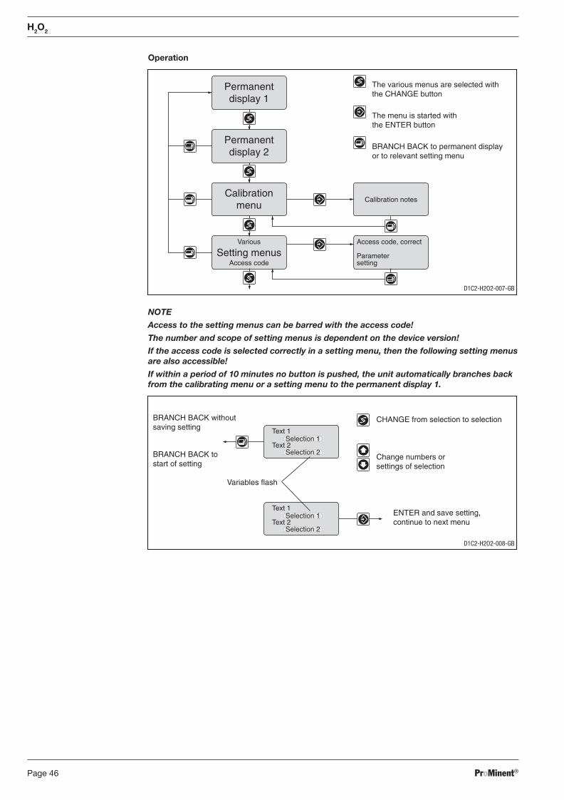
ProMinent®Page 46
Operation
H2O2
NOTE
Access to the setting menus can be barred with the access code!
The number and scope of setting menus is dependent on the device version!
If the access code is selected correctly in a setting menu, then the following setting menus are also accessible!
If within a period of 10 minutes no button is pushed, the unit automatically branches back from the calibrating menu or a setting menu to the permanent display 1.
Access code, correct
Parametersetting
Calibration notes
Permanentdisplay 1
Permanentdisplay 2
Calibrationmenu
Various
Access codeSetting menus
The various menus are selected withthe CHANGE button
The menu is started withthe ENTER button
BRANCH BACK to permanent displayor to relevant setting menu
D1C2-H2O2-007-GB
CHANGE from selection to selection
Change numbers orsettings of selection
Variables flash
ENTER and save setting,continue to next menu
BRANCH BACK withoutsaving setting
BRANCH BACK tostart of setting
Text 1
Text 2Selection 1
Selection 2
Text 1
Text 2Selection 1
Selection 2
D1C2-H2O2-008-GB
BA_DR_001_02_09_GB.indd 46BA_DR_001_02_09_GB.indd 46 24.02.2009 12:24:02 Uhr24.02.2009 12:24:02 Uhr
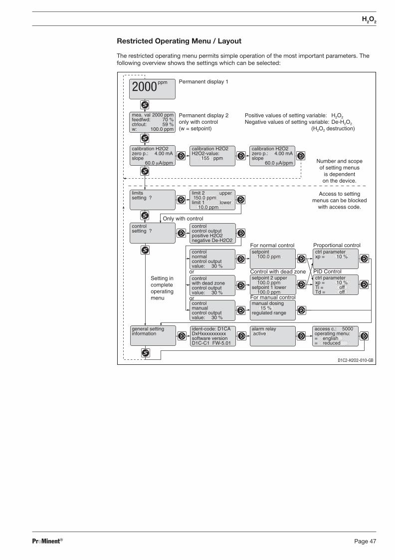
ProMinent® Page 47
Positive values of setting variable: H2O2
Negative values of setting variable: De-H2O2
(H2O2 destruction)
Permanent display 1
Permanent display 2only with control(w = setpoint)
Control with dead zone
For normal control
PID Control
Proportional control
Only with control
mea. val 2000 ppmfeedfwd: 70 %ctrlout: 59 %w: 100.0 ppm
calibration H2O2zero p.: 4.00 mAslope
60.0 μA/ppm
calibration H2O2H2O2-value:
155 ppm
calibration H2O2zero p.: 4.00 mAslope
60.0 μA/ppm
limitssetting ?
limit 2 upper150.0 ppm
limit 1 lower10.0 ppm
controlsetting ?
controlnormalcontrol outputvalue: 30 %
setpoint100.0 ppm
ctrl parameterxp = 10 %
controlwith dead zonecontrol outputvalue: 30 %
setpoint 2 upper100.0 ppm
setpoint 1 lower100.0 ppm
controlmanualcontrol outputvalue: 30 %
manual dosing15 %
regulated range
general settinginformation
ident-code: D1CADxHxxxxxxxxxxsoftware versionD1C-C1 FW-5.01
alarm relay active
access c.: 5000operating menu:= english= reduced
Number and scopeof setting menus
is dependenton the device.
Access to settingmenus can be blocked
with access code.
ctrl parameterxp = 10 %Ti = offTd = off
For manual control
or
or
Setting incompleteoperatingmenu
ppm2000
controlcontrol outputpositive H2O2negative De-H2O2
H2O2
Restricted Operating Menu / Layout
The restricted operating menu permits simple operation of the most important parameters. The following overview shows the settings which can be selected:
D1C2-H2O2-010-GB
BA_DR_001_02_09_GB.indd 47BA_DR_001_02_09_GB.indd 47 24.02.2009 12:24:02 Uhr24.02.2009 12:24:02 Uhr
ProMinent®Page 48
8.3.2 DULCOTEST® PER Sensor for Hydrogen Peroxide, Commissioning
8.3.2.1 DULCOTEST® PER Sensor for Hydrogen Peroxide, Assembly
Assembly
CAUTION
• Protective goggles and protective clothing should be worn when handling water and solutions containing H2O2!
• Do not swallow the electrolyte. If electrolyte comes into contact with the eyes or skin, rinse the affected areas thoroughly with water! If reddening of the eyes occurs, con sult an eye specialist!
IMPORTANT
• Do not touch or damage the membrane and electrodes!
• Always keep electrolyte bottles tightly closed after use! Do not transfer electrolyte into any other bottles or containers.
• The electrolyte should not be kept for more than 1 year! (See label for use-by date).
• The membrane cap may only be used once!
Pouring electrolyte � Remove the membrane protection cap and unscrew the membrane cap from the electrode shaft.
� Fill the membrane cap with electrolyte up to the lower thread, if possible bubble-free.
If you wish to considerably reduce the running-in time, you must expel the air between the gauze and the membrane (as the air is expelled, the membrane is visible by refl ecting through the electrolyte as it is being fi lled).
There are two ways of doing this:
1. � Tap the membrane cap lightly from the side, from the bottom and from the top with the sensor
shaft until the air bubbles stop rising (you can see this in good light).
2.
� Fill the enclosed pipette with electrolyte from the membrane cap, if possible up to the top. Please ensure that no air is taken in.
� Take the opening of the pipette as close as possible to the membrane (through the electrolyte) and place a couple of drops on it from the pipette (do not release any air from the pipette when doing this!)
IMPORTANT
After using the pipette, rinse thoroughly with water and store in the original sensor pack-ag ing!
Assembling membrane cap � Insert the fi nger nail below both rubber seals at the semi-circular pocket in the membrane cap (the vent is positioned there) and pull the rubber seals to the bottom until the needle top-sized vent becomes visible and hold the seals. When screwing together, excess electrolyte should escape freely through the vent such that the membrane is not damaged by excess pressure.
� Position the electrode shaft vertically on the fi lled membrane cap.
� Do not obstruct the vent with your fi ngers.
� Screw the electrode shaft manually into the membrane cap up to the stop such that there is no free gap between the membrane cap and the electrode shaft.
� Re-insert the rubber seals fl ush into the groove of the membrane cap.
H2O2
BA_DR_001_02_09_GB.indd 48BA_DR_001_02_09_GB.indd 48 24.02.2009 12:24:02 Uhr24.02.2009 12:24:02 Uhr
ProMinent® Page 49
H2O2
IMPORTANT
• Depressurise the system before installing the sensor in the fl ow housing. Close stop valves to the front and rear of the in-line probe housing.
• Placing/removing the sensor into/from the in-line probe housing should be done slowly.
• Do not exceed the maximum permitted operating pressure of 1 bar!
• Ensure the fl ow does not fall below the minimum fl ow rate of 30 l/h! Monitor the fl ow on the connected measurement and control equipment. If the meas-ured value is used as a control, switch off the control by reducing to below the minimum fl ow rate or switch to basic load.
• Avoid installations which allow air bubbles to build up in the sample water. Air bubbles that cling to the diaphragm of the sensor can cause the measured value to be too small and thus may lead to incorrect metering in the control system.
Fitting the sensor in the in-line probe housing Observe the operation and safety instructions con tained in the operating instructions manual for
the in-line probe housing!
DLG III � Push the O-ring up over the sensor as far as the terminal block.
� Insert the sensor into the DLG III.
� Tighten the sensor with thread plugs.
DGM � Push the O-ring up over the sensor as far as the terminal block; leave a plain washer in the DGM.
� Insert the sensor into the DGM and fi t tightly with terminal screw until the O-ring is sealed: the terminal block determines the correct depth for fi tting the sensor.
8.3.2.2 DULCOTEST® PER Sensor for Hydrogen Peroxide, Electrical Installation
General Safety Instructions
IMPORTANT
• Install the equipment so that the power supply for the controller never falls below the minimum! A power supply that is too low causes errors in measured values and can lead to over metering in a control system!
• The sensor PER is a sensor with a passive 4-20 mA two-wire interface. The power is supplied externally or from a mea suring and control system. Connection to the DULCOMETER® D1C controller from ProMinent ensures automatic compliance with inter face safety requirements.
• When electrically connecting the sensor to the measur ing equipment, only use signal cables with a diameter of 4 mm.
Electrical Installation
� Turn the upper section of the sensor anti-clockwise through 90° and remove.
� Strip the outer insulation back by about 5 cm so that both con nectors are visible.
� Loosen the M-12 connection and feed the 2-connector cable through it. Whilst doing this, keep the two-connector signal cable in the sensor (5 cm).
� Strip the insulation from both ends of the cable and connect to the terminal, as shown in the fi g. (use the screw driver provided). 1 = plus, 2 = minus
� Tighten the M-12 connection.
� Turn the upper section of the sensor clockwise fi rmly as far as the stop.
BA_DR_001_02_09_GB.indd 49BA_DR_001_02_09_GB.indd 49 24.02.2009 12:24:02 Uhr24.02.2009 12:24:02 Uhr
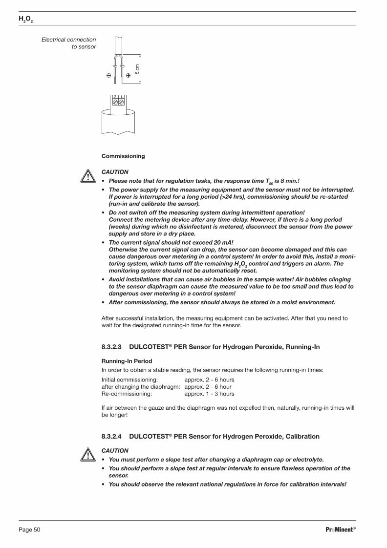
ProMinent®Page 50
Electrical connection to sensor
1 2
5 cm
Commissioning
CAUTION
• Please note that for regulation tasks, the response time T90 is 8 min.!
• The power supply for the measuring equipment and the sensor must not be interrupted. If power is inter rupted for a long period (>24 hrs), commissioning should be re-started (run-in and calibrate the sensor).
• Do not switch off the measuring system during intermittent operation! Connect the metering device after any time-delay. However, if there is a long period (weeks) during which no disinfectant is metered, disconnect the sensor from the power supply and store in a dry place.
• The current signal should not exceed 20 mA! Otherwise the current signal can drop, the sensor can become damaged and this can cause dangerous over metering in a control system! In order to avoid this, install a moni-toring system, which turns off the remaining H2O2 control and triggers an alarm. The monitoring system should not be automatically reset.
• Avoid installations that can cause air bubbles in the sample water! Air bubbles clinging to the sensor diaphragm can cause the measured value to be too small and thus lead to dangerous over metering in a control system!
• After commissioning, the sensor should always be stored in a moist environment.
After successful installation, the measuring equip ment can be acti vated. After that you need to wait for the designated running-in time for the sensor.
8.3.2.3 DULCOTEST® PER Sensor for Hydrogen Peroxide, Running-In
Running-In Period
In order to obtain a stable reading, the sensor requires the following running-in times:
Initial commissioning: approx. 2 - 6 hours after changing the diaphragm: approx. 2 - 6 hour Re-commissioning: approx. 1 - 3 hours
If air between the gauze and the diaphragm was not expelled then, naturally, running-in times will be longer!
8.3.2.4 DULCOTEST® PER Sensor for Hydrogen Peroxide, Calibration
CAUTION
• You must perform a slope test after changing a diaphragm cap or electrolyte.
• You should perform a slope test at regular intervals to ensure fl awless operation of the sensor.
• You should observe the relevant national regulations in force for calibration intervals!
H2O2
BA_DR_001_02_09_GB.indd 50BA_DR_001_02_09_GB.indd 50 24.02.2009 12:24:02 Uhr24.02.2009 12:24:02 Uhr
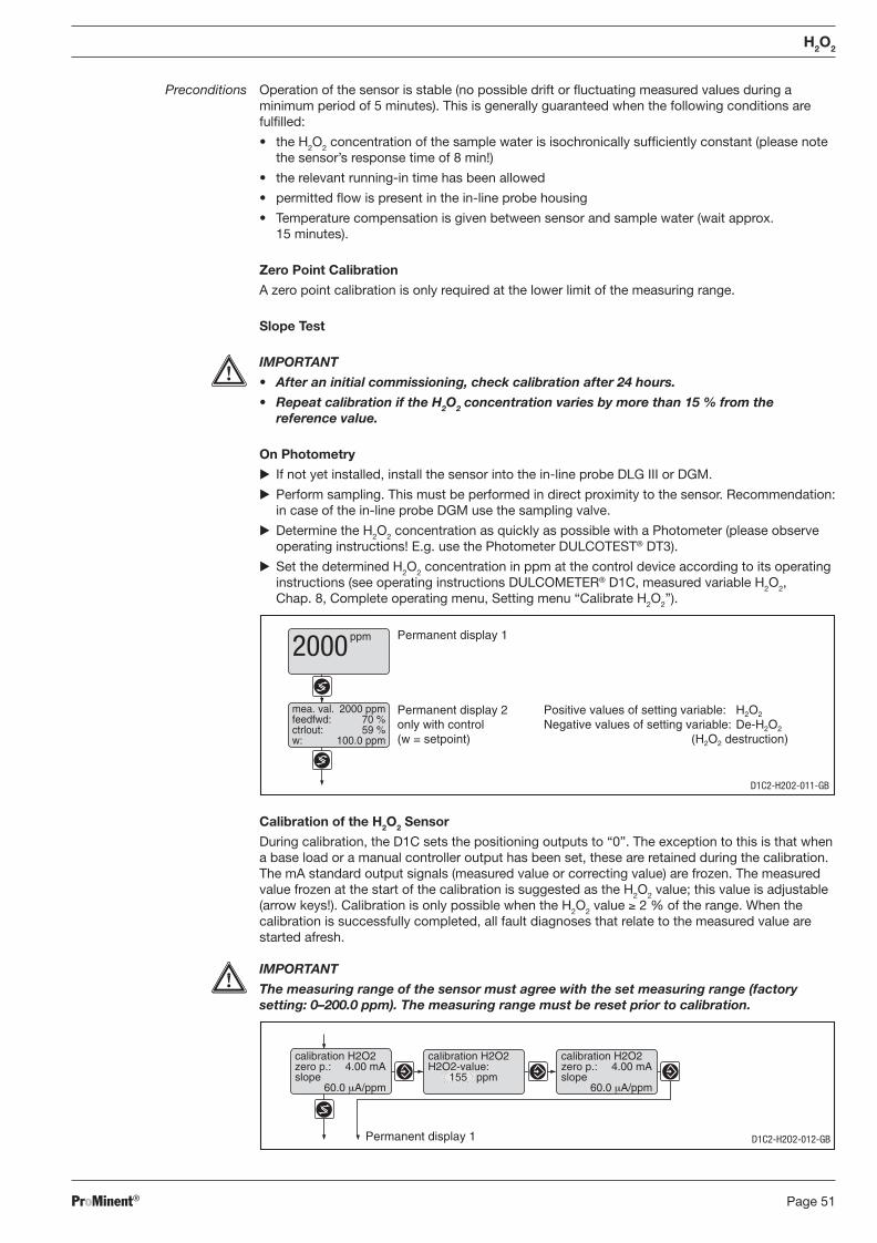
ProMinent® Page 51
Permanent display 1
calibration H2O2zero p.: 4.00 mAslope
60.0 μA/ppm
calibration H2O2zero p.: 4.00 mAslope
60.0 μA/ppm
calibration H2O2H2O2-value:
155 ppm
D1C2-H2O2-012-GB
Permanent display 1
Permanent display 2only with control(w = setpoint)
Positive values of setting variable: H2O2
Negative values of setting variable: De-H2O2
(H2O2 destruction)
mea. val. 2000 ppmfeedfwd: 70 %ctrlout: 59 %w: 100.0 ppm
ppm2000
D1C2-H2O2-011-GB
H2O2
Preconditions Operation of the sensor is stable (no possible drift or fl uctua ting measured values during a minimum period of 5 minutes). This is generally guaranteed when the following conditions are fulfi lled:
• the H2O2 concentration of the sample water is isochronically suffi ciently constant (please note the sensor’s response time of 8 min!)
• the relevant running-in time has been allowed
• permitted fl ow is present in the in-line probe housing
• Temperature compensation is given between sensor and sample water (wait approx. 15 minutes).
Zero Point Calibration
A zero point calibration is only required at the lower limit of the measuring range.
Slope Test
IMPORTANT
• After an initial commissioning, check calibration after 24 hours.
• Repeat calibration if the H2O2 concentration varies by more than 15 % from the reference value.
On Photometry
� If not yet installed, install the sensor into the in-line probe DLG III or DGM.
� Perform sampling. This must be performed in direct proximity to the sensor. Recommendation: in case of the in-line probe DGM use the sampling valve.
� Determine the H2O2 concentration as quickly as possible with a Photometer (please observe operating instructions! E.g. use the Photometer DULCOTEST® DT3).
� Set the determined H2O2 concentration in ppm at the control device according to its operating instructions (see operating instructions DULCOMETER® D1C, measured variable H2O2, Chap. 8, Complete operating menu, Setting menu “Calibrate H2O2”).
Calibration of the H2O2 Sensor
During calibration, the D1C sets the positioning outputs to “0”. The exception to this is that when a base load or a manual controller output has been set, these are retained during the calibration. The mA standard output signals (measured value or correcting value) are frozen. The measured value frozen at the start of the calibration is suggested as the H2O2 value; this value is adjustable (arrow keys!). Calibration is only possible when the H2O2 value ≥ 2 % of the range. When the calibration is successfully completed, all fault diagnoses that relate to the measured value are started afresh.
IMPORTANT
The measuring range of the sensor must agree with the set measuring range (factory setting: 0–200.0 ppm). The measuring range must be reset prior to calibration.
BA_DR_001_02_09_GB.indd 51BA_DR_001_02_09_GB.indd 51 24.02.2009 12:24:02 Uhr24.02.2009 12:24:02 Uhr
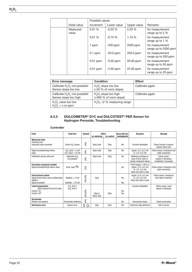
ProMinent®Page 52
Fault Fault text Symbol Effect Alarm with ack- Remarks Remedy on metering on control nowledgement
Measured value Checkout time measured value exceeded Check H2O2 sensor Basic load Stop Yes Function defeatable Check function of sensor, extend check time
Signal exceeded/drops below H2O2 input < 3 mA Basic load Stop Yes Signal <3.0 ±0.2 mA Check sensor, transducer and value H2O2 input > 23 mA or >23 ±0.2 mA cable connection
Calibration sensor with error calibration H2O2 Basic load Stop No Metering continues in Check sensor, not possible! case of error with un- replace if necessary, steady measured values recalibrate if necessary
Correction measured variable Pt100-signal >138.5 Ω Signal exceeded/drops below value temp. input yes Signal <3.0 ±0.2 mA Check sensor, transducer and or >23 ±0.2 mA cable connection Value last valid is used
Feed forward control Signal <3.8 ±0.2 mA Check sensor, transducer Signal drops below value multiplicative feedfwd. < 4 mA Stop Yes or >23 ±0.2 mA and cable connection additive Value last valid is used Signal exceeded feedfwd. > 23 mA Yes
Limit transgression H2O2 limit 1 Function defeatable Defi ne cause, reset after checkout time limit value H2O2 limit 2 values if necessary Control “on” Yes Control “off” Stop or Stop Yes Basic load
Servomotor Position not reached Servomotor defective Yes Servomotor closes Check servomotor
Electronics error System error Stop Stop Yes Elektronic data defective Call in service
8.3.3 DULCOMETER® D1C and DULCOTEST® PER Sensor for Hydrogen Peroxide, Troubleshooting
Controller
H2O2
Possible values
Initial value Increment Lower value Upper value Remarks
Measured 0.01 % -0.20 % 2.20 % for measurement value range up to 2 %
0.01 % -0.10 % 1.10 % for measurement range up to 1 %
1 ppm -200 ppm 2200 ppm for measurement range up to 2000 ppm
0.1 ppm -20.0 ppm 220.0 ppm for measurement range up to 200 ppm
0.01 ppm -5.00 ppm 55.00 ppm for measurement range up to 50 ppm
0.01 ppm -2.00 ppm 22.00 ppm for measurement range up to 20 ppm
Error message Condition Effect
Calibrate H2O2 not possible! H2O2 slope too low Calibrate again Sensor slope too low (<25 % of norm slope)
Calibrate H2O2 not possible! H2O2 slope too high Calibrate again Sensor slope too high (>300 % of norm slope)
H2O2 value too low H2O2 <2 % measuring range H2O2 > x.xx ppm
BA_DR_001_02_09_GB.indd 52BA_DR_001_02_09_GB.indd 52 24.02.2009 12:24:02 Uhr24.02.2009 12:24:02 Uhr
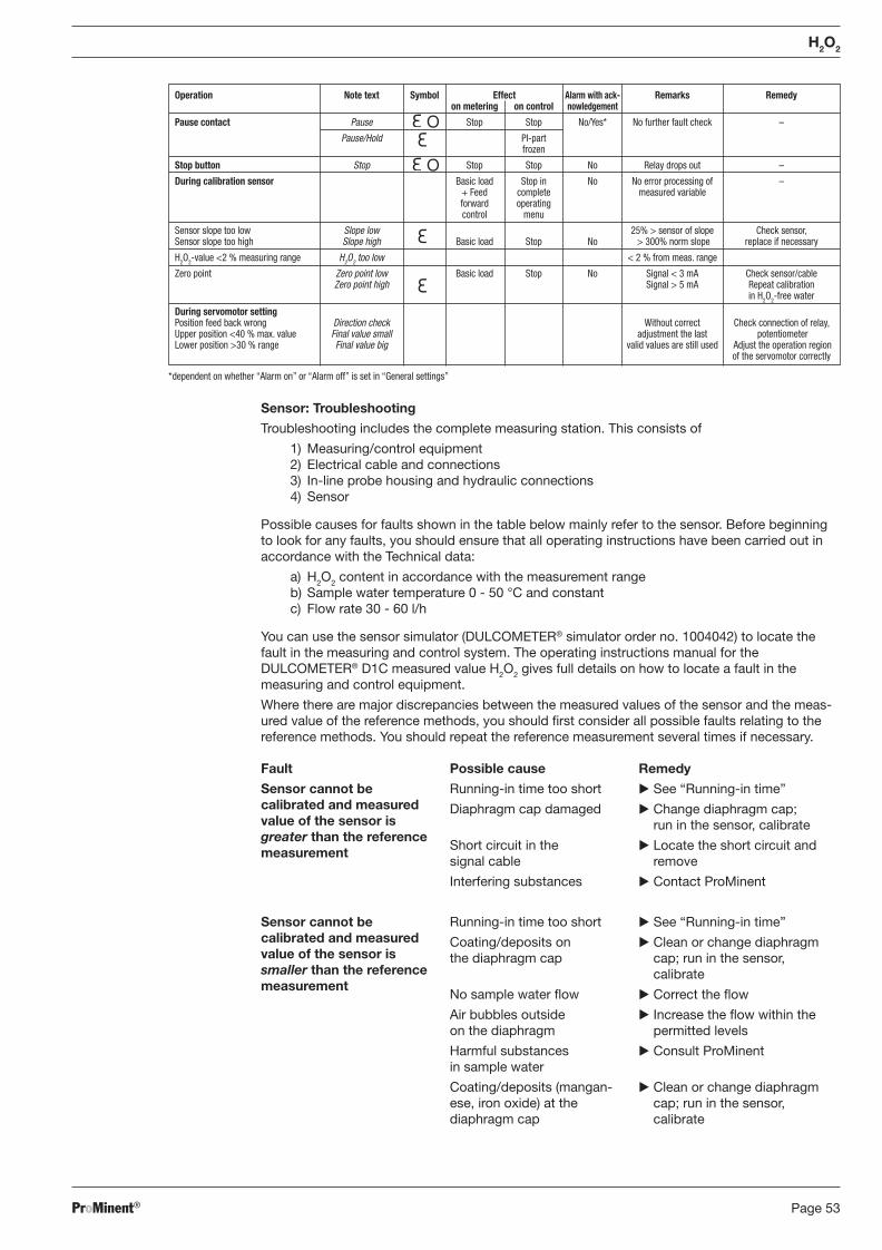
ProMinent® Page 53
Operation Note text Symbol Effect Alarm with ack- Remarks Remedy on metering on control nowledgement
Pause contact Pause Stop Stop No/Yes* No further fault check –
Pause/Hold PI-part frozen
Stop button Stop Stop Stop No Relay drops out –
During calibration sensor Basic load Stop in No No error processing of – + Feed complete measured variable forward operating control menu
Sensor slope too low Slope low 25% > sensor of slope Check sensor, Sensor slope too high Slope high Basic load Stop No > 300% norm slope replace if necessary
H2O2-value <2 % measuring range H2O2 too low < 2 % from meas. range
Zero point Zero point low Basic load Stop No Signal < 3 mA Check sensor/cable Zero point high Signal > 5 mA Repeat calibration in H2O2-free water
During servomotor setting Position feed back wrong Direction check Without correct Check connection of relay, Upper position <40 % max. value Final value small adjustment the last potentiometer Lower position >30 % range Final value big valid values are still used Adjust the operation region of the servomotor correctly
*dependent on whether “Alarm on” or “Alarm off” is set in “General settings”
Sensor: Troubleshooting
Troubleshooting includes the complete measuring station. This consists of
1) Measuring/control equipment 2) Electrical cable and connections 3) In-line probe housing and hydraulic connections 4) Sensor
Possible causes for faults shown in the table below mainly refer to the sensor. Before beginning to look for any faults, you should ensure that all operating instructions have been carried out in accordance with the Technical data:
a) H2O2 content in accordance with the measurement range b) Sample water temperature 0 - 50 °C and constant c) Flow rate 30 - 60 l/h
You can use the sensor simulator (DULCOMETER® simulator order no. 1004042) to locate the fault in the measuring and control system. The operating instructions manual for the DULCOMETER® D1C measured value H2O2 gives full details on how to locate a fault in the measuring and control equipment.
Where there are major discrepancies between the measured values of the sensor and the meas-ured value of the reference methods, you should fi rst consider all possible faults relating to the reference methods. You should repeat the reference measurement several times if necessary.
H2O2
Fault
Sensor cannot be calibrated and measured value of the sensor is greater than the reference measurement
Sensor cannot be calibrated and measured value of the sensor is smaller than the reference measurement
Possible cause
Running-in time too short
Diaphragm cap damaged
Short circuit in the signal cable
Interfering substances
Running-in time too short
Coating/deposits on the diaphragm cap
No sample water fl ow
Air bubbles outside on the diaphragm
Harmful substances in sample water
Coating/deposits (mangan-ese, iron oxide) at the diaphragm cap
Remedy
� See “Running-in time”
� Change diaphragm cap; run in the sensor, calibrate
� Locate the short circuit and remove
� Contact ProMinent
� See “Running-in time”
� Clean or change diaphragm cap; run in the sensor, calibrate
� Correct the fl ow
� Increase the fl ow within the permitted levels
� Consult ProMinent
� Clean or change diaphragm cap; run in the sensor, calibrate
BA_DR_001_02_09_GB.indd 53BA_DR_001_02_09_GB.indd 53 24.02.2009 12:24:02 Uhr24.02.2009 12:24:02 Uhr
ProMinent®Page 54
H2O2
* If the reference electrode has a silvery sheen or looks white, it needs to be regenerated. Brownish-grey discolouration is however normal.
** To isolate faults, the current in the sensor can be displayed via the DULCOMETER® D1C whilst the latter is electrically connected to the sensor. For this purpose read the value in “zero point” in the setting menu “H2O2 calibration” in the complete operation menu, see operating instructions DULCOMETER® D1C, chap. 8. Do not confi rm by pressing the Enter key, but exit the menu using the Back key.
8.3.4 DULCOMETER® D1C Measured Variable H2O2 and DULCOTEST® PER Sensor for Hydrogen Peroxide, Maintenance
Controller
The DULCOMETER® controller type D1C for the measured variable H2O2 is maintenance-free.
Sensor
IMPORTANT
� Maintain the sensor regularly in order to avoid over metering in a control system result-ing from an incorrect measured value!
� Observe the relevant national regulations in force for fre quency of maintenance!
� Do not touch the electrodes or bring them into contact with greasy substances!
� Do not unscrew the membrane cap when cleaning the membrane!
Maintenance interval Figures based on experience for: media with minor dirt contamination: 1 month Other applications: depending on operating conditions
Fault Possible cause Remedy
Sensor measured value is 0 ppm
Sensor measured value is 0 ppm and error message appears at the DULCOMETER® D1C controller “H2O2 input < 3 mA”
Sensor measured value is 0 ppm and sensor current is between 3.0 and 4.0 mA**
Error message at DULCOMETER® D1C controller “H2O2 input > 23 mA“
Sensor measured value is unstable
No electrolyte in the diaphragm cap
Sensor connected to controller with incorrect polarity
Signal cable broken
Defective sensor
Defective control equipment
Running-in time too short
Defective reference electrode*
H2O2 content exceeds upper limit of measuring range
Defective sensor
Defective reference electrode*
Process-related
� Use new diaphragm cap and fi ll in new electrolyte (see “Mounting”, “Running-in Period” and “Calibration”
� Connect the sensor correctly to the controller
� Change signal cable
� Return the sensor
� Check the control equipment with sensor simulator (DULCOMETER® Simulator, order no.1004042), return if defective
� See “Running-in time”
� Return the sensor for regeneration
� Check system, remedy the defect repeat calibration
� Return the sensor
� Return the sensor for regeneration
� Optimise control process
BA_DR_001_02_09_GB.indd 54BA_DR_001_02_09_GB.indd 54 24.02.2009 12:24:03 Uhr24.02.2009 12:24:03 Uhr
ProMinent® Page 55
Maintenance Work
� Check the sensor regularly for dirt, deposits and air bubbles! Avoid, as far as is possible, contamination of the membrane with particles, deposits/ sediments, etc. Eliminate air bubbles by in creasing the fl ow.
� Check the sensor display value at the control equipment regularly using suitable reference methods (Photometry).
� If necessary, re-calibrate the sensor.
� If calibration is no longer possible, clean or replace the membrane cap and then repeat calibration (see “Assembly”, “Running-in time” and “Calibration”).
Cleaning the Membrane
� Do not unscrew the membrane cap!
� Wipe the membrane with a damp cloth.
H2O2
BA_DR_001_02_09_GB.indd 55BA_DR_001_02_09_GB.indd 55 24.02.2009 12:24:03 Uhr24.02.2009 12:24:03 Uhr
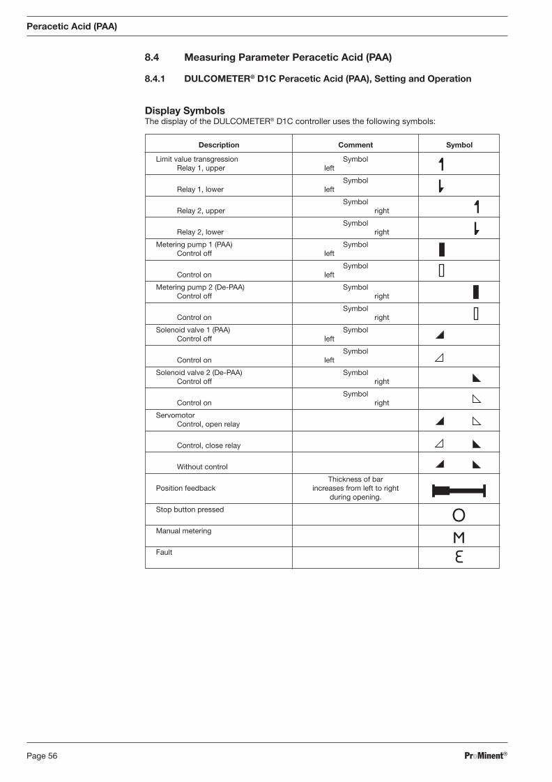
ProMinent®Page 56
Description Comment Symbol
Limit value transgression Symbol Relay 1, upper left
Symbol Relay 1, lower left
Symbol Relay 2, upper right
Symbol Relay 2, lower right
Metering pump 1 (PAA) Symbol Control off left
Symbol Control on left
Metering pump 2 (De-PAA) Symbol Control off right
Symbol Control on right
Solenoid valve 1 (PAA) Symbol Control off left
Symbol Control on left
Solenoid valve 2 (De-PAA) Symbol Control off right
Symbol Control on right
Servomotor Control, open relay
Control, close relay
Without control
Thickness of bar Position feedback increases from left to right during opening.
Stop button pressed
Manual metering
Fault
Peracetic Acid (PAA)
8.4 Measuring Parameter Peracetic Acid (PAA)
8.4.1 DULCOMETER® D1C Peracetic Acid (PAA), Setting and Operation
Display Symbols The display of the DULCOMETER® D1C controller uses the following symbols:
BA_DR_001_02_09_GB.indd 56BA_DR_001_02_09_GB.indd 56 24.02.2009 12:24:03 Uhr24.02.2009 12:24:03 Uhr
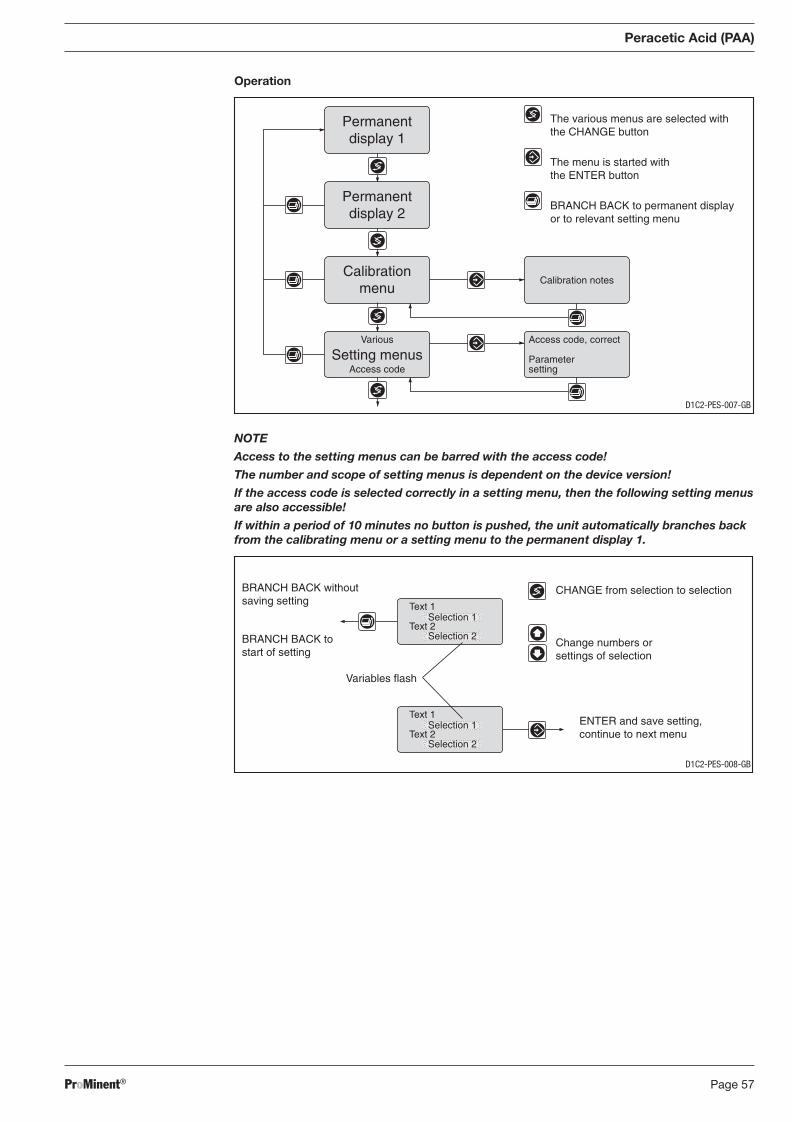
ProMinent® Page 57
Operation
NOTE
Access to the setting menus can be barred with the access code!
The number and scope of setting menus is dependent on the device version!
If the access code is selected correctly in a setting menu, then the following setting menus are also accessible!
If within a period of 10 minutes no button is pushed, the unit automatically branches back from the calibrating menu or a setting menu to the permanent display 1.
Peracetic Acid (PAA)
CHANGE from selection to selection
Change numbers orsettings of selection
Variables flash
ENTER and save setting,continue to next menu
BRANCH BACK withoutsaving setting
BRANCH BACK tostart of setting
Text 1
Text 2Selection 1
Selection 2
Text 1
Text 2Selection 1
Selection 2
D1C2-PES-008-GB
Access code, correct
Parametersetting
Calibration notes
Permanentdisplay 1
Permanentdisplay 2
Calibrationmenu
Various
Access codeSetting menus
The various menus are selected withthe CHANGE button
The menu is started withthe ENTER button
BRANCH BACK to permanent displayor to relevant setting menu
D1C2-PES-007-GB
BA_DR_001_02_09_GB.indd 57BA_DR_001_02_09_GB.indd 57 24.02.2009 12:24:03 Uhr24.02.2009 12:24:03 Uhr
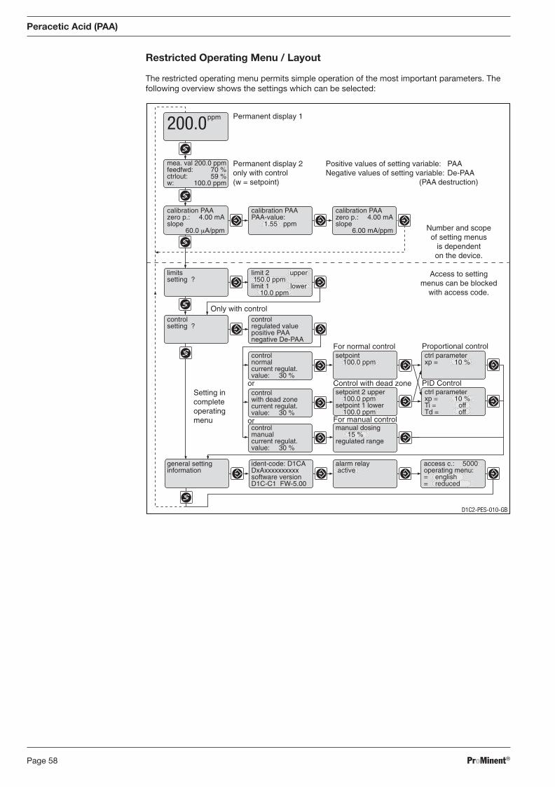
ProMinent®Page 58
Positive values of setting variable: PAANegative values of setting variable: De-PAA
(PAA destruction)
Permanent display 1
Permanent display 2only with control(w = setpoint)
Control with dead zone
For normal control
PID Control
Proportional control
Only with control
mea. val 200.0 ppmfeedfwd: 70 %ctrlout: 59 %w: 100.0 ppm
calibration PAAzero p.: 4.00 mAslope
60.0 μA/ppm
calibration PAAPAA-value:
1.55 ppm
calibration PAAzero p.: 4.00 mAslope
6.00 mA/ppm
limitssetting ?
limit 2 upper150.0 ppm
limit 1 lower10.0 ppm
controlsetting ?
controlregulated valuepositive PAAnegative De-PAA
controlnormalcurrent regulat.value: 30 %
setpoint100.0 ppm
ctrl parameterxp = 10 %
controlwith dead zonecurrent regulat.value: 30 %
setpoint 2 upper100.0 ppm
setpoint 1 lower100.0 ppm
controlmanualcurrent regulat.value: 30 %
manual dosing15 %
regulated range
general settinginformation
ident-code: D1CADxAxxxxxxxxxxsoftware versionD1C-C1 FW-5.00
alarm relay active
access c.: 5000operating menu:= english= reduced
Number and scopeof setting menus
is dependenton the device.
Access to settingmenus can be blocked
with access code.
ctrl parameterxp = 10 %Ti = offTd = off
For manual control
or
or
Setting incompleteoperatingmenu
ppm200.0
Peracetic Acid (PAA)
Restricted Operating Menu / Layout
The restricted operating menu permits simple operation of the most important parameters. The following overview shows the settings which can be selected:
D1C2-PES-010-GB
BA_DR_001_02_09_GB.indd 58BA_DR_001_02_09_GB.indd 58 24.02.2009 12:24:03 Uhr24.02.2009 12:24:03 Uhr
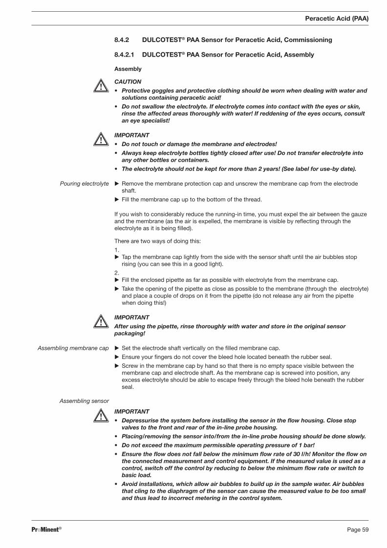
ProMinent® Page 59
8.4.2 DULCOTEST® PAA Sensor for Peracetic Acid, Commissioning
8.4.2.1 DULCOTEST® PAA Sensor for Peracetic Acid, Assembly
Assembly
CAUTION
• Protective goggles and protective clothing should be worn when dealing with water and solutions containing peracetic acid!
• Do not swallow the electrolyte. If electrolyte comes into contact with the eyes or skin, rinse the affected areas thoroughly with water! If reddening of the eyes occurs, con sult an eye specialist!
IMPORTANT
• Do not touch or damage the membrane and electrodes!
• Always keep electrolyte bottles tightly closed after use! Do not transfer electrolyte into any other bottles or containers.
• The electrolyte should not be kept for more than 2 years! (See label for use-by date).
Pouring electrolyte � Remove the membrane protection cap and unscrew the membrane cap from the electrode shaft.
� Fill the membrane cap up to the bottom of the thread.
If you wish to considerably reduce the running-in time, you must expel the air between the gauze and the membrane (as the air is expelled, the membrane is visible by refl ecting through the electrolyte as it is being fi lled).
There are two ways of doing this:
1. � Tap the membrane cap lightly from the side with the sensor shaft until the air bubbles stop
rising (you can see this in a good light).
2. � Fill the enclosed pipette as far as possible with electrolyte from the membrane cap.
� Take the opening of the pipette as close as possible to the membrane (through the electrolyte) and place a couple of drops on it from the pipette (do not release any air from the pipette when doing this!)
IMPORTANT
After using the pipette, rinse thoroughly with water and store in the original sensor pack ag ing!
Assembling membrane cap � Set the electrode shaft vertically on the fi lled membrane cap.
� Ensure your fi ngers do not cover the bleed hole located beneath the rubber seal.
� Screw in the membrane cap by hand so that there is no empty space visible between the membrane cap and electrode shaft. As the membrane cap is screwed into position, any excess electrolyte should be able to escape freely through the bleed hole beneath the rubber seal.
Assembling sensor
IMPORTANT
• Depressurise the system before installing the sensor in the fl ow housing. Close stop valves to the front and rear of the in-line probe housing.
• Placing/removing the sensor into/from the in-line probe housing should be done slowly.
• Do not exceed the maximum permissible operating pressure of 1 bar!
• Ensure the fl ow does not fall below the minimum fl ow rate of 30 l/h! Monitor the fl ow on the connected measurement and control equipment. If the measured value is used as a control, switch off the control by reducing to below the minimum fl ow rate or switch to basic load.
• Avoid installations, which allow air bubbles to build up in the sample water. Air bubbles that cling to the diaphragm of the sensor can cause the measured value to be too small and thus lead to incorrect metering in the control system.
Peracetic Acid (PAA)
BA_DR_001_02_09_GB.indd 59BA_DR_001_02_09_GB.indd 59 24.02.2009 12:24:03 Uhr24.02.2009 12:24:03 Uhr
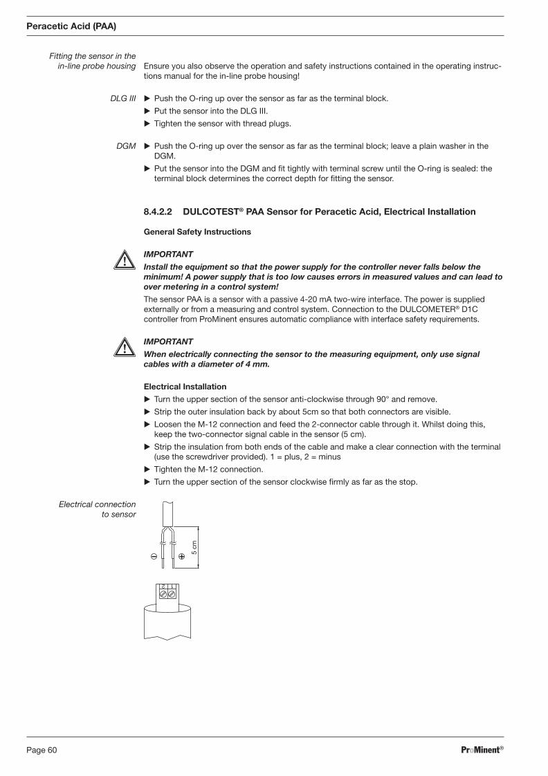
ProMinent®Page 60
Peracetic Acid (PAA)
Fitting the sensor in the in-line probe housing Ensure you also observe the operation and safety instructions con tained in the operating instruc-
tions manual for the in-line probe housing!
DLG III � Push the O-ring up over the sensor as far as the terminal block.
� Put the sensor into the DLG III.
� Tighten the sensor with thread plugs.
DGM � Push the O-ring up over the sensor as far as the terminal block; leave a plain washer in the DGM.
� Put the sensor into the DGM and fi t tightly with terminal screw until the O-ring is sealed: the terminal block determines the correct depth for fi tting the sensor.
8.4.2.2 DULCOTEST® PAA Sensor for Peracetic Acid, Electrical Installation
General Safety Instructions
IMPORTANT
Install the equipment so that the power supply for the controller never falls below the minimum! A power supply that is too low causes errors in measured values and can lead to over metering in a control system!
The sensor PAA is a sensor with a passive 4-20 mA two-wire interface. The power is supplied externally or from a mea suring and control system. Connection to the DULCOMETER® D1C controller from ProMinent ensures automatic compliance with inter face safety requirements.
IMPORTANT
When electrically connecting the sensor to the measur ing equipment, only use signal cables with a diameter of 4 mm.
Electrical Installation
� Turn the upper section of the sensor anti-clockwise through 90° and remove.
� Strip the outer insulation back by about 5cm so that both con nectors are visible.
� Loosen the M-12 connection and feed the 2-connector cable through it. Whilst doing this, keep the two-connector signal cable in the sensor (5 cm).
� Strip the insulation from both ends of the cable and make a clear connection with the terminal (use the screw driver provided). 1 = plus, 2 = minus
� Tighten the M-12 connection.
� Turn the upper section of the sensor clockwise fi rmly as far as the stop.
Electrical connection to sensor
BA_DR_001_02_09_GB.indd 60BA_DR_001_02_09_GB.indd 60 24.02.2009 12:24:03 Uhr24.02.2009 12:24:03 Uhr
ProMinent® Page 61
Peracetic Acid (PAA)
Commissioning
CAUTION
• The power supply for the measuring equipment and the sensor must not be interrupted. If power is inter rupted for a long period (>24 hrs) commissioning should be re-started (run-in and calibrate the sensor).
• Do not switch off the measuring system during interval operation! After operation without peracetic acid, running-in periods are to be reckoned with. If required, switch on metering unit time-delayed! If no peracetic acid is metered for a longer period of time, the sensor must be discon-nected from the power supply and stored dry.
• The current signal should not exceed 20 mA! Otherwise the current signal can drop, the sensor can become damaged and this can cause dangerous over metering in a control system! In order to avoid this, install a monitoring system, which turns off the remaining per-acetic acid control and raises an alarm. The monitoring system should not be automati-cally reset.
• Avoid installations that can cause air bubbles in the sample water! Air bubbles clinging to the sensor diaphragm can cause the measured value to be too small and thus lead to dangerous over metering in a control system!
• After commissioning, the sensor should always be stored in a moist environment.
After successful installation, you can switch on the measuring equip ment. After that you need to wait for the designated running-in time for the sensor.
8.4.2.3 DULCOTEST® PAA Sensor for Peracetic Acid, Running-In
Running-In Period
In order to achieve a stable reading, the sensor requires the following running-in times:
Initial commissioning: approx. 1-2 hours after changing the diaphragm: approx. 1 hour Re-commissioning: approx. 1-2 hours
If air between the gauze and the diaphragm was not expelled then, naturally, running-in times will be longer!
8.4.2.4 DULCOTEST® PAA Sensor for Peracetic Acid, Calibration
CAUTION
• You must perform a slope test after changing a diaphragm cap or electrolyte.
• You should perform a slope test at regular intervals to ensure fl awless operation of the sensor.
• You should observe the relevant national regulations in force for calibration intervals!
Preconditions Operation of the sensor is stable (no possible drift or fl uctua ting measured values during a minimum period of 5 minutes). This is generally guaranteed when the following conditions are fulfi lled:
• The relevant running-in time has been allowed
• Permitted fl ow is present in the in-line probe housing
• Temperature compensation achieved between sensor and sample water (wait approx. 15 minutes).
Zero Point Calibration
Zero point calibration is not required.
BA_DR_001_02_09_GB.indd 61BA_DR_001_02_09_GB.indd 61 24.02.2009 12:24:03 Uhr24.02.2009 12:24:03 Uhr
ProMinent®Page 62
Peracetic Acid (PAA)
Slope Test
IMPORTANT
• After an initial commissioning, check calibration after 24 hours.
• Repeat calibration if the PAA concentration varies by more than 15 % from the reference value.
There are two ways of performing a slope test for the peracetic acid (PAA) sensor:
• via two-stage titration
• via a PAA standard solution (with a known PAA concentration)
Regarding Two-Stage Titration
NOTE
Calibration on a bottle-washing machine should only be per formed after a long uninterrup-ted period of operation, or when the bottle-washing machine has stopped (PAA concen-tration remains constant).
If calibrating whilst the bottle-washing machine is running, you should prepare everything for titration in the laboratory in advance and measure the sample as soon as possible after taking it.
� If it has not already been done, fi t the sensor in the in-line probe housing DLG III or DGM.
� Take a sample for titration. You should do this in the immediate vicinity of the sensor. Tip: for the DGM in-line probe housing, use the sample extraction valve.
� Determine the PAA concentration as quickly as possible.
� Adjust the value ascertained for PAA concentration in ppm on the control equipment in accordance with the relevant opera ting instructions manual (see operating instructions manual for DULCOMETER® D1C for the measured value peracetic acid, chap. 8, complete operating menu, set-up menu “PAA cali bration”).
Regarding PAA Standard Solution
� Add a known concentration of PAA to a standard solution e.g. in the cup of the DLG III in-line probe housing.
� Stir the contents of the cup using a magnetic stirring rod.
� Immerse the sensor in the cup until the measured value remains constant (15 minutes).
� Set the given PAA concentration value for the standard solution in ppm in the control equip-ment in accordance with the operating instructions manual (see operating instructions manual for the DULCOMETER® D1C for the measured value peracetic acid, chap. 8, complete operating menu, set-up menu “PAA calibra tion”).
BA_DR_001_02_09_GB.indd 62BA_DR_001_02_09_GB.indd 62 24.02.2009 12:24:03 Uhr24.02.2009 12:24:03 Uhr
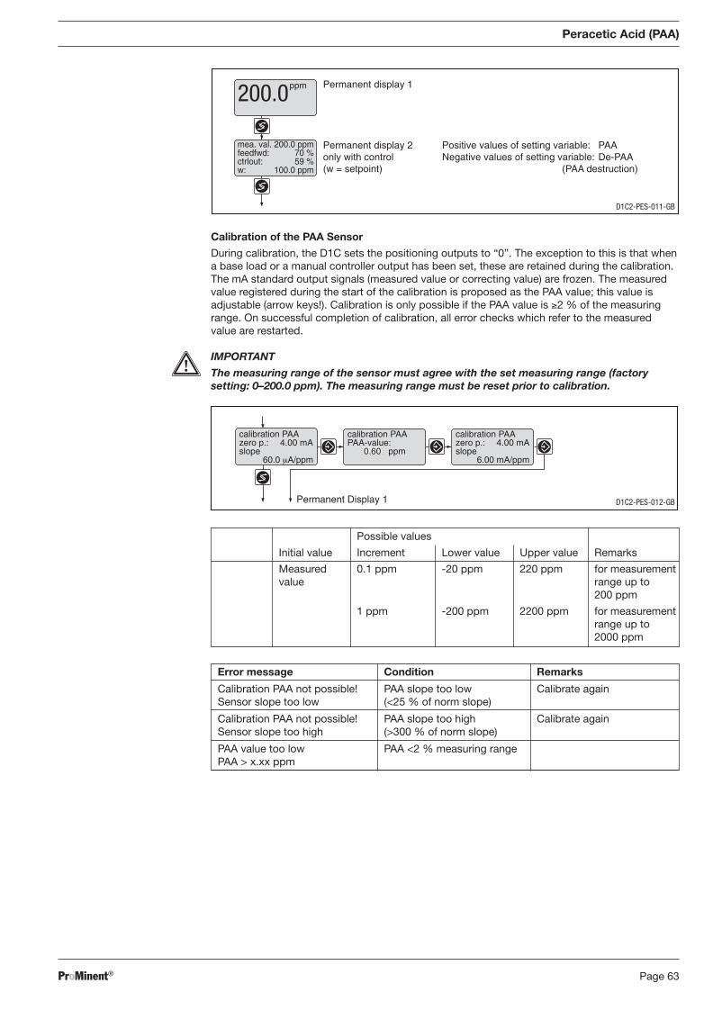
ProMinent® Page 63
Permanent display 1
Permanent display 2only with control(w = setpoint)
Positive values of setting variable: PAANegative values of setting variable: De-PAA
(PAA destruction)
mea. val. 200.0 ppmfeedfwd: 70 %ctrlout: 59 %w: 100.0 ppm
ppm200.0
Calibration of the PAA Sensor
During calibration, the D1C sets the positioning outputs to “0”. The exception to this is that when a base load or a manual controller output has been set, these are retained during the calibration. The mA standard output signals (measured value or correcting value) are frozen. The measured value registered during the start of the calibration is proposed as the PAA value; this value is adjustable (arrow keys!). Calibration is only possible if the PAA value is ≥2 % of the measuring range. On successful completion of calibration, all error checks which refer to the measured value are restarted.
IMPORTANT
The measuring range of the sensor must agree with the set measuring range (factory setting: 0–200.0 ppm). The measuring range must be reset prior to calibration.
Peracetic Acid (PAA)
Error message Condition Remarks
Calibration PAA not possible! PAA slope too low Calibrate again Sensor slope too low (<25 % of norm slope)
Calibration PAA not possible! PAA slope too high Calibrate again Sensor slope too high (>300 % of norm slope)
PAA value too low PAA <2 % measuring range PAA > x.xx ppm
Permanent Display 1
calibration PAAzero p.: 4.00 mAslope
60.0 μA/ppm
calibration PAAzero p.: 4.00 mAslope
6.00 mA/ppm
calibration PAAPAA-value:
0.60 ppm
D1C2-PES-012-GB
D1C2-PES-011-GB
Possible values
Initial value Increment Lower value Upper value Remarks
Measured 0.1 ppm -20 ppm 220 ppm for measurement value range up to 200 ppm
1 ppm -200 ppm 2200 ppm for measurement range up to 2000 ppm
BA_DR_001_02_09_GB.indd 63BA_DR_001_02_09_GB.indd 63 24.02.2009 12:24:03 Uhr24.02.2009 12:24:03 Uhr
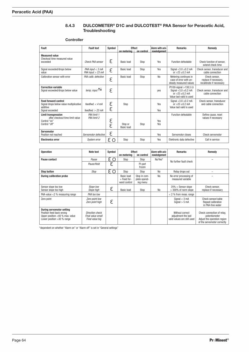
ProMinent®Page 64
Operation Note text Symbol Effect Alarm with ack- Remarks Remedy on metering on control nowledgement
Pause contact Pause Stop Stop No/Yes* No further fault check
–
Pause/Hold PI-part frozen
Stop button Stop Stop Stop No Relay drops out –
During calibration probe Basic load Stop in com- No No error processing of – + Feed for- plete operat- measured variable ward control ing menu
Sensor slope too low Slope low 25% > Sensor slope Check sensor, Sensor slope too high Slope high Basic load Stop No > 300% of norm slope replace if necessary
PAA-value <2 % measuring range PAA too low < 2 % from meas. range
Zero point Zero point low Signal < 3 mA Check sensor/cable Zero point high Signal > 5 mA Repeat calibration in PAA-free water
During servomotor setting Position feed back wrong Direction check Without correct Check connection of relay, Upper position <40 % max. value Final value small adjustment the last potentiometer Lower position >30 % range Final value big valid values are still used Adjust the operation region of the servomotor correctly
*dependent on whether “Alarm on” or “Alarm off” is set in “General settings”
8.4.3 DULCOMETER® D1C and DULCOTEST® PAA Sensor for Peracetic Acid, Troubleshooting
Controller
Fault Fault text Symbol Effect Alarm with ack- Remarks Remedy on metering on control nowledgement Measured value Checkout time measured value exceeded Check PAA sensor Basic load Stop Yes Function defeatable Check function of sensor, extend check time
Signal exceeded/drops below PAA input < 3 mA Basic load Stop Yes Signal <3.0 ±0.2 mA Check sensor, transducer and value PAA input > 23 mA or >23 ±0.2 mA cable connection
Calibration sensor with error PAA calib. defective Basic load Stop No Metering continues in Check sensor, case of error with un- replace if necessary, steady measured values recalibrate if necessary
Correction variable Pt100-signal >138,5 Ω Signal exceeded/drops below value temp. input yes Signal <3,0 ±0,2 mA Check sensor, transducer and or >23 ±0,2 mA cable connection Value last valid is used
Feed forward control Signal <3.8 ±0.2 mA Check sensor, transducer Signal drops below value multiplicative feedfwd. < 4 mA Stop Yes or >23 ±0.2 mA and cable connection additive Value last valid is used Signal exceeded feedfwd. > 23 mA Yes
Limit transgression PAA limit 1 Function defeatable Defi ne cause, reset after checkout time limit value PAA limit 2 values if necessary Control “on” Yes Control “off” Stop or Stop Yes Basic load
Servomotor Position not reached Servomotor defective Yes Servomotor closes Check servomotor
Electronics error System error Stop Stop Yes Elektronic data defective Call in service
Peracetic Acid (PAA)
BA_DR_001_02_09_GB.indd 64BA_DR_001_02_09_GB.indd 64 24.02.2009 12:24:03 Uhr24.02.2009 12:24:03 Uhr
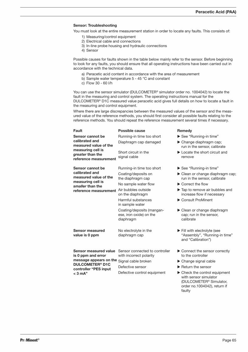
ProMinent® Page 65
Sensor: Troubleshooting
You must look at the entire measurement station in order to locate any faults. This consists of:
1) Measuring/control equipment 2) Electrical cable and connections 3) In-line probe housing and hydraulic connections 4) Sensor
Possible causes for faults shown in the table below mainly refer to the sensor. Before beginning to look for any faults, you should ensure that all operating instructions have been carried out in accordance with the technical data.
a) Peracetic acid content in accordance with the area of measurement b) Sample water temperature 5 - 45 °C and constant c) Flow 30 - 60 l/h
You can use the sensor simulator (DULCOMETER® simulator order no. 1004042) to locate the fault in the measuring and control system. The operating instructions manual for the DULCOMETER® D1C measured value peracetic acid gives full details on how to locate a fault in the measuring and control equipment.
Where there are large discrepancies between the measured values of the sensor and the meas-ured value of the reference methods, you should fi rst consider all possible faults relating to the reference methods. You should repeat the reference measurement several times if necessary.
Peracetic Acid (PAA)
Fault
Sensor cannot be calibrated and meas ured value of the measuring cell is greater than the
reference measurement
Sensor cannot be calibrated and measured value of the measuring cell is smaller than the reference measurement
Sensor measured value is 0 ppm
Sensor measured value is 0 ppm and error message appears on the DULCOMETER® D1C controller “PES input < 3 mA”
Possible cause
Running-in time too short
Diaphragm cap damaged
Short circuit in the signal cable
Running-in time too short
Coating/deposits on the diaphragm cap
No sample water fl ow
Air bubbles outside on the diaphragm
Harmful substances in sample water
Coating/deposits (mangan-ese, iron oxide) on the diaphragm
No electrolyte in the diaphragm cap
Sensor connected to controller with incorrect polarity
Signal cable broken
Defective sensor
Defective control equipment
Remedy
� See “Running-in time”
� Change diaphragm cap; run in the sensor, calibrate
� Locate the short circuit and remove
� See “Running-in time”
� Clean or change diaphragm cap; run in the sensor, calibrate
� Correct the fl ow
� Tap to remove air bubbles and increase fl ow if necessary
� Consult ProMinent
� Clean or change diaphragm cap; run in the sensor, calibrate
� Fill with electrolyte (see “Assembly”, “Running-in time” and “Calibration”)
� Connect the sensor correctly to the controller
� Change signal cable
� Return the sensor
� Check the control equipment with sensor simulator (DULCOMETER® Simulator, order no.1004042), return if faulty
BA_DR_001_02_09_GB.indd 65BA_DR_001_02_09_GB.indd 65 24.02.2009 12:24:03 Uhr24.02.2009 12:24:03 Uhr
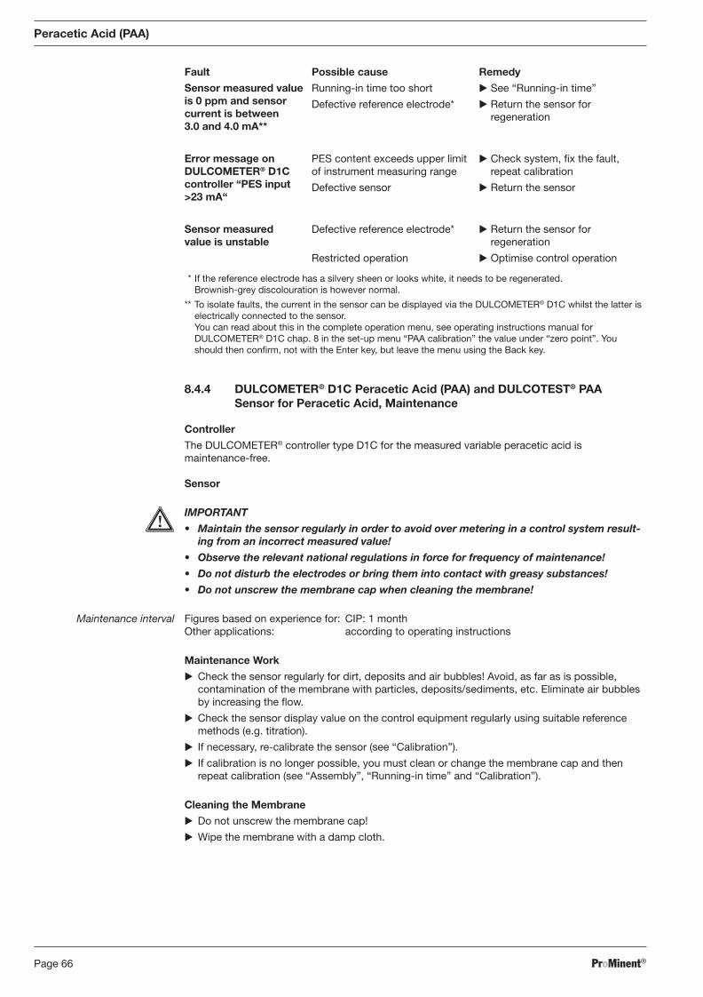
ProMinent®Page 66
Peracetic Acid (PAA)
Fault Possible cause Remedy
* If the reference electrode has a silvery sheen or looks white, it needs to be regenerated. Brownish-grey discolouration is however normal.
** To isolate faults, the current in the sensor can be displayed via the DULCOMETER® D1C whilst the latter is electrically connected to the sensor. You can read about this in the complete operation menu, see operating instructions manual for DULCOMETER® D1C chap. 8 in the set-up menu “PAA calibration” the value under “zero point”. You should then confi rm, not with the Enter key, but leave the menu using the Back key.
Sensor measured value is 0 ppm and sensor current is between 3.0 and 4.0 mA**
Error message on DULCOMETER® D1C controller “PES input >23 mA“
Sensor measured value is unstable
Running-in time too short
Defective reference electrode*
PES content exceeds upper limit of instrument measuring range
Defective sensor
Defective reference electrode*
Restricted operation
� See “Running-in time”
� Return the sensor for regeneration
� Check system, fi x the fault, repeat calibration
� Return the sensor
� Return the sensor for regeneration
� Optimise control operation
8.4.4 DULCOMETER® D1C Peracetic Acid (PAA) and DULCOTEST® PAA Sensor for Peracetic Acid, Maintenance
Controller
The DULCOMETER® controller type D1C for the measured variable peracetic acid is maintenance-free.
Sensor
IMPORTANT
• Maintain the sensor regularly in order to avoid over metering in a control system result-ing from an incorrect measured value!
• Observe the relevant national regulations in force for fre quency of maintenance!
• Do not disturb the electrodes or bring them into contact with greasy substances!
• Do not unscrew the membrane cap when cleaning the membrane!
Maintenance interval Figures based on experience for: CIP: 1 month Other applications: according to operating instructions
Maintenance Work
� Check the sensor regularly for dirt, deposits and air bubbles! Avoid, as far as is possible, contamination of the membrane with particles, deposits/sediments, etc. Eliminate air bubbles by in creasing the fl ow.
� Check the sensor display value on the control equipment regularly using suitable reference methods (e.g. titration).
� If necessary, re-calibrate the sensor (see “Calibration”).
� If calibration is no longer possible, you must clean or change the membrane cap and then repeat calibration (see “Assembly”, “Running-in time” and “Calibration”).
Cleaning the Membrane
� Do not unscrew the membrane cap!
� Wipe the membrane with a damp cloth.
BA_DR_001_02_09_GB.indd 66BA_DR_001_02_09_GB.indd 66 24.02.2009 12:24:03 Uhr24.02.2009 12:24:03 Uhr
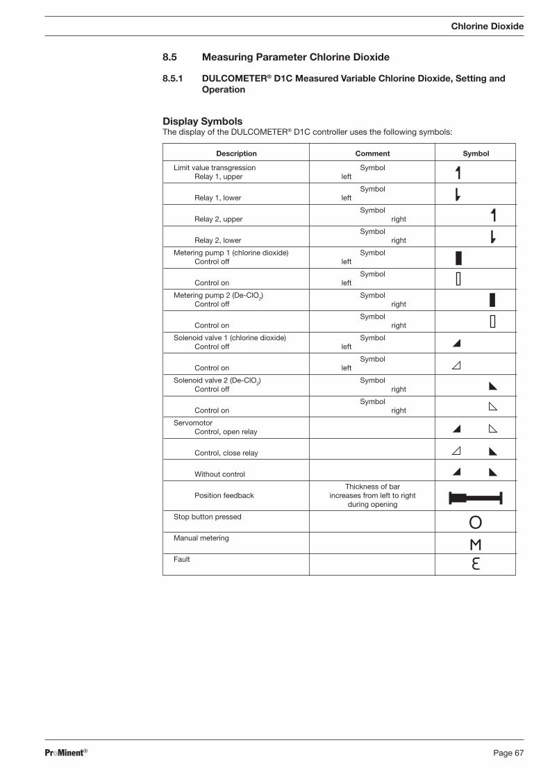
ProMinent® Page 67
8.5 Measuring Parameter Chlorine Dioxide
8.5.1 DULCOMETER® D1C Measured Variable Chlorine Dioxide, Setting and Operation
Display Symbols The display of the DULCOMETER® D1C controller uses the following symbols:
Description Comment Symbol
Limit value transgression Symbol Relay 1, upper left
Symbol Relay 1, lower left
Symbol Relay 2, upper right
Symbol Relay 2, lower right
Metering pump 1 (chlorine dioxide) Symbol Control off left
Symbol Control on left
Metering pump 2 (De-ClO2) Symbol Control off right
Symbol Control on right
Solenoid valve 1 (chlorine dioxide) Symbol Control off left
Symbol Control on left
Solenoid valve 2 (De-ClO2) Symbol Control off right
Symbol Control on right
Servomotor Control, open relay
Control, close relay
Without control
Thickness of bar Position feedback increases from left to right during opening
Stop button pressed
Manual metering
Fault
Chlorine Dioxide
BA_DR_001_02_09_GB.indd 67BA_DR_001_02_09_GB.indd 67 24.02.2009 12:24:04 Uhr24.02.2009 12:24:04 Uhr
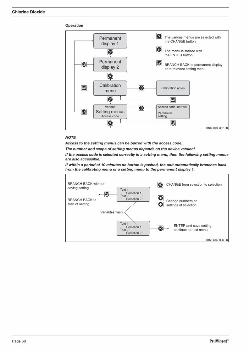
ProMinent®Page 68
Operation
Chlorine Dioxide
NOTE
Access to the setting menus can be barred with the access code!
The number and scope of setting menus depends on the device version!
If the access code is selected correctly in a setting menu, then the following setting menus are also accessible!
If within a period of 10 minutes no button is pushed, the unit automatically branches back from the calibrating menu or a setting menu to the permanent display 1.
Access code, correct
Parametersetting
Calibration notes
Permanentdisplay 1
Permanentdisplay 2
Calibrationmenu
Various
Access codeSetting menus
The various menus are selected withthe CHANGE button
The menu is started withthe ENTER button
BRANCH BACK to permanent displayor to relevant setting menu
CHANGE from selection to selection
Change numbers orsettings of selection
Variables flash
ENTER and save setting,continue to next menu
BRANCH BACK withoutsaving setting
BRANCH BACK tostart of setting
Text 1
Text 2Selection 1
Selection 2
Text 1
Text 2Selection 1
Selection 2
D1C2-CIO2-007-GB
D1C2-CIO2-008-GB
BA_DR_001_02_09_GB.indd 68BA_DR_001_02_09_GB.indd 68 24.02.2009 12:24:04 Uhr24.02.2009 12:24:04 Uhr
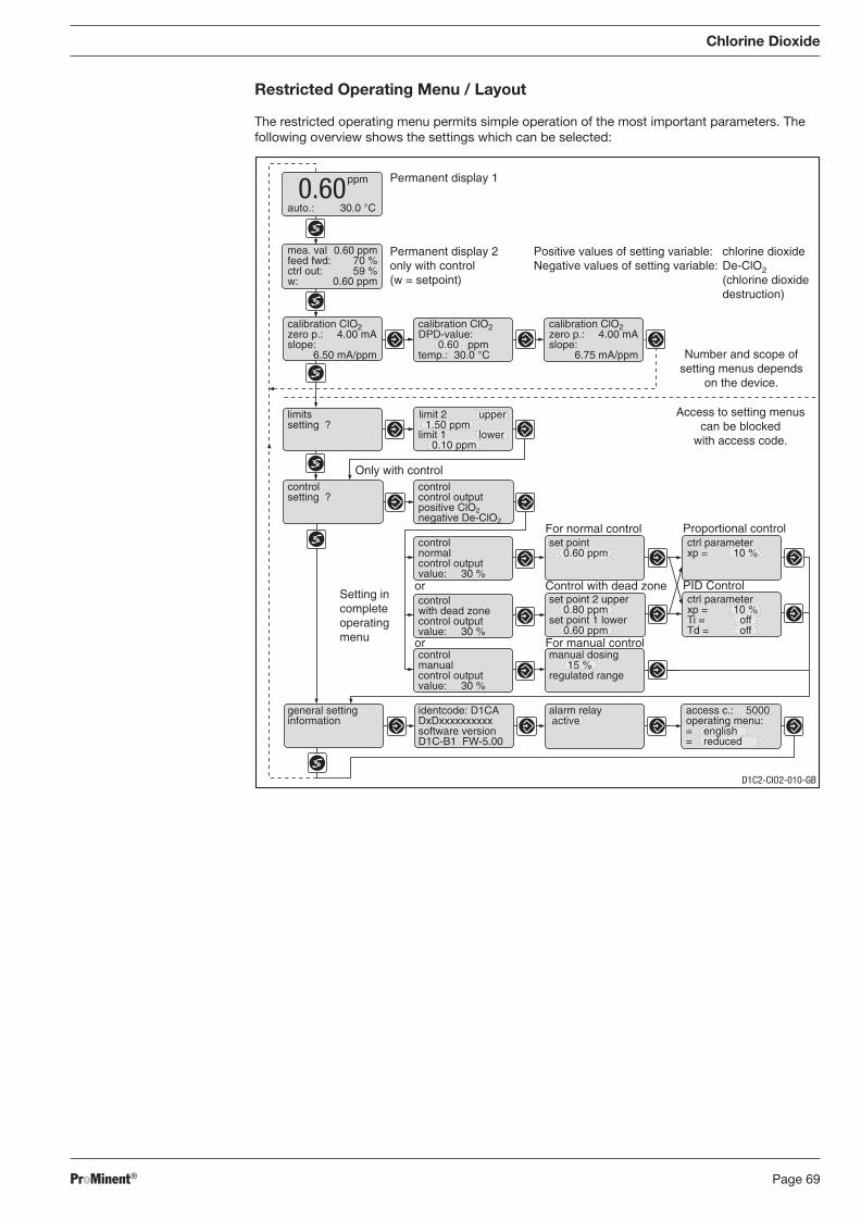
ProMinent® Page 69
Positive values of setting variable: chlorine dioxideNegative values of setting variable: De-ClO2
(chlorine dioxidedestruction)
auto.: 30.0 °C
Permanent display 1
Permanent display 2only with control(w = setpoint)
Control with dead zone
For normal control
PID Control
Proportional control
Only with control
ppm0.60
mea. val 0.60 ppmfeed fwd: 70 %ctrl out: 59 %w: 0.60 ppm
calibration ClO2zero p.: 4.00 mAslope:
6.50 mA/ppm
calibration ClO2DPD-value:
0.60 ppmtemp.: 30.0 °C
calibration ClO2zero p.: 4.00 mAslope:
6.75 mA/ppm
limitssetting ?
controlsetting ?
controlnormalcontrol outputvalue: 30 %
set point0.60 ppm
ctrl parameterxp = 10 %
controlwith dead zonecontrol outputvalue: 30 %
set point 2 upper0.80 ppm
set point 1 lower0.60 ppm
controlmanualcontrol outputvalue: 30 %
manual dosing15 %
regulated range
general settinginformation
identcode: D1CADxDxxxxxxxxxxsoftware versionD1C-B1 FW-5.00
alarm relay active
access c.: 5000operating menu:= english= reduced
Access to setting menuscan be blocked
with access code.
Setting incompleteoperatingmenu For manual control
or
or
ctrl parameterxp = 10 %Ti = offTd = off
limit 1 lower0.10 ppm
limit 2 upper1.50 ppm
Number and scope ofsetting menus depends
on the device.
controlcontrol outputpositive ClO2negative De-ClO2
D1C2-CIO2-010-GB
Chlorine Dioxide
Restricted Operating Menu / Layout
The restricted operating menu permits simple operation of the most important parameters. The following overview shows the settings which can be selected:
BA_DR_001_02_09_GB.indd 69BA_DR_001_02_09_GB.indd 69 24.02.2009 12:24:04 Uhr24.02.2009 12:24:04 Uhr
ProMinent®Page 70
Chlorine Dioxide
8.5.2 DULCOTEST® CDE Chlorine Dioxide Sensor, Commissioning
8.5.2.1 DULCOTEST® CDE Chlorine Dioxide Sensor, Assembly
Assembly
Pouring electrolyte
IMPORTANT
• The membrane at the lower end of the membrane cap and the electrodes at the lower end of the electrode shaft should not be touched, damaged or brought into contact with greasy substances! Otherwise the sensor will not work correctly. If this is the case, replace membrane cap or return the sensor for cleaning the electrodes.
• Protect yourself and your clothing from contact with the electrolyte (acid!) using appro-priate protective equipment. The electrolyte can cause irritation to skin and damage to clothing. In case of contact, rinse immediately with plenty of cold water.
NOTE
Carry out the following steps at the washbasin!
� Open the electrolyte bottle and screw on the nozzle.
� Remove the red cap completely from the nozzle and cut off the end of the nozzle.
� Remove the membrane cap and unscrew the membrane cap from the electrode shaft.
� Rinse the membrane cap and the electrode with a small amount of electrolyte.
� Fill the membrane cap up the top with electrolyte and allow electrolyte to overfl ow down the inside wall.
Assembling membrane cap � Locate the electrode shaft vertically onto the fi lled membrane cap and turn until the thread bites.
� Rotate the membrane cap so that the vent hole is at the top.
� Slowly screw on the membrane cap by hand up to the stop. In the process the excess electro-lyte will seep out of the vent hole.
� Rinse sensor under running water to remove excess electrolyte from the sensor and from hands.
Assembling sensor
IMPORTANT
• The sensor must be slowly inserted into or withdrawn from the in-line probe housing! The membrane could otherwise be damaged.
• Do not touch the in-line probe housing fl ow resistor with the membrane!
• The sensor must be kept wet at all times once commissioned - e.g. the in-line probe housing must not be allowed to run dry.
Assemble the sensor as described in the operating instructions supplied with the in-line probe housing.
8.5.2.2 DULCOTEST® CDE Chlorine Dioxide Sensor, Electrical Installation
IMPORTANT
• The sensor is not electrically isolated from the sample water. All other elements must be isolated! The controller must be isolated both from the sensor and from the supply voltage!
• The supply voltage must not fall below 16 V DC, even for a short period! The current source must able to sustain 35 mA at a min. 16 V DC! Insuffi cient supply voltage will result in an inaccurate reading!
• After the electrical connection of the sensor, the sensor has to be inserted into the sample water which has to contain chlorine dioxide.
BA_DR_001_02_09_GB.indd 70BA_DR_001_02_09_GB.indd 70 24.02.2009 12:24:04 Uhr24.02.2009 12:24:04 Uhr
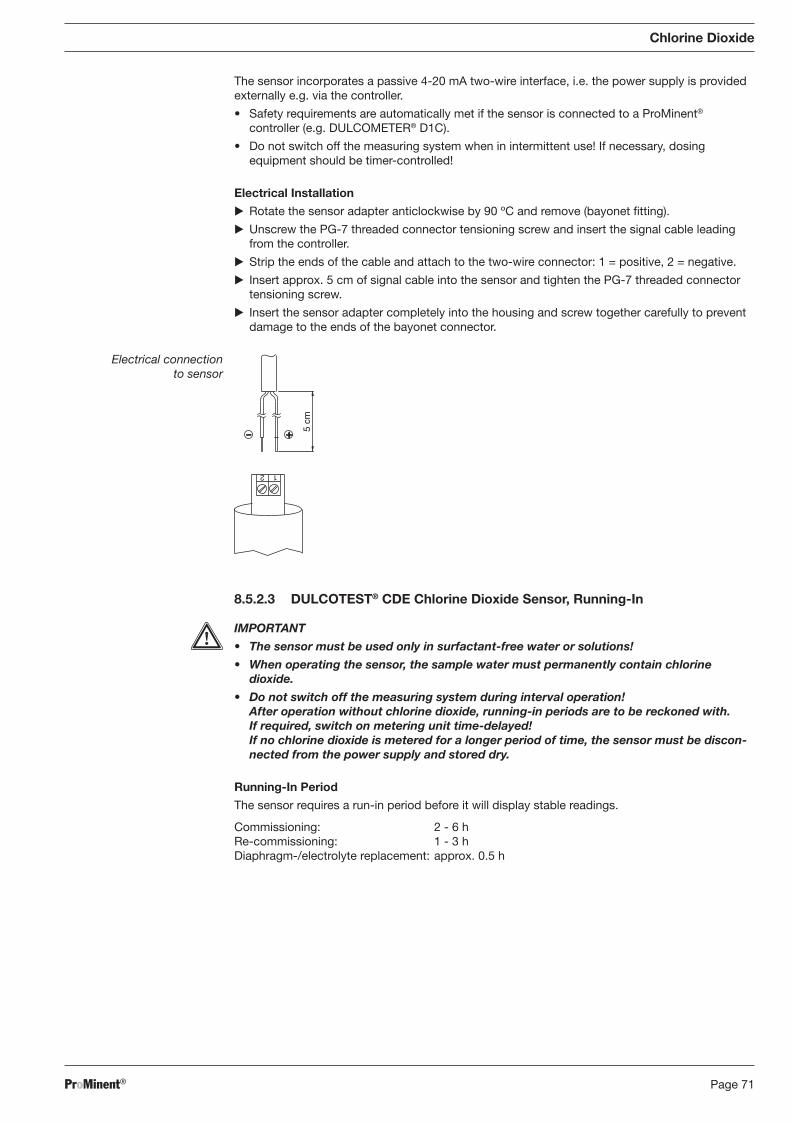
ProMinent® Page 71
Chlorine Dioxide
The sensor incorporates a passive 4-20 mA two-wire interface, i.e. the power supply is provided externally e.g. via the controller.
• Safety requirements are automatically met if the sensor is connected to a ProMinent® con trol ler (e.g. DULCOMETER® D1C).
• Do not switch off the measuring system when in intermittent use! If necessary, dosing equipment should be timer-controlled!
Electrical Installation
� Rotate the sensor adapter anticlockwise by 90 ºC and remove (bayonet fi tting).
� Unscrew the PG-7 threaded connector tensioning screw and insert the signal cable leading from the controller.
� Strip the ends of the cable and attach to the two-wire connector: 1 = positive, 2 = negative.
� Insert approx. 5 cm of signal cable into the sensor and tighten the PG-7 threaded connector tensioning screw.
� Insert the sensor adapter completely into the housing and screw together carefully to prevent damage to the ends of the bayonet connector.
Electrical connection to sensor
1 2
5 cm
8.5.2.3 DULCOTEST® CDE Chlorine Dioxide Sensor, Running-In
IMPORTANT
• The sensor must be used only in surfactant-free water or solutions!
• When operating the sensor, the sample water must permanently contain chlorine dioxide.
• Do not switch off the measuring system during interval operation! After operation without chlorine dioxide, running-in periods are to be reckoned with. If required, switch on metering unit time-delayed! If no chlorine dioxide is metered for a longer period of time, the sensor must be discon-nected from the power supply and stored dry.
Running-In Period
The sensor requires a run-in period before it will display stable readings.
Commissioning: 2 - 6 h Re-commissioning: 1 - 3 h Diaphragm-/electrolyte replacement: approx. 0.5 h
BA_DR_001_02_09_GB.indd 71BA_DR_001_02_09_GB.indd 71 24.02.2009 12:24:04 Uhr24.02.2009 12:24:04 Uhr
ProMinent®Page 72
Chlorine Dioxide
8.5.2.4 DULCOTEST® CDE Chlorine Dioxide Sensor, Calibration
The sensor can be calibrated after the run-in period.
IMPORTANT
• A slope test must be carried out after replacing the diaphragm cap or electrolyte!
• Slope tests must be carried out at regular intervals to ensure correct functioning of the sensor! For testing drinking water, calibration of the sensor every 3 - 4 weeks is suf fi cient.
• Avoid incorrect dosing due to air bubbles in the water. Air bubbles clinging to the sensor diaphragm can reduce the measured variable and thereby lead to overdosing.
• Observe applicable national directives for calibration intervals!
Preconditions • Constant fl ow to the in-line probe housing
• Constant sample water temperature
• Same sample water and sensor temperatures (wait approx. 15 min.)
Zero Point Calibration
If a ProMinent controller is being used to operate the sensor there is no need for zero point calibration. Zero point calibration should be carried out, however, if operating the sensor in the lower measurement range, or if using the 0.5 ppm variant.
Preconditions • The sensor has been run in
• Flow to the in-line probe housing is constant and complies with technical datas
� Insert the sensor into a container of clean, ozone- and ClO2-free water.
� Stir with the sensor until the measured variable displayed at the controller has remained stable for 5 min.
� Calibrate the controller to zero in accordance with the operating instructions.
� Replace sensor into the in-line probe housing (DGM; DLG).
Slope Test
� Determine the chlorine dioxide content in the sample water using an appropriate measurement device (e.g. DPD-1).
� Set the resulting value at the controller in accordance with the operating instructions.
Repeat calibration after 1 day!
NOTE
Calibration at high temperatures
As chlorine dioxide, in contrast to chlorine, is only physically dissolved in water, it evap o rates out of the liquid very quickly at high temperatures (> 30 °C). We therefore rec om mend that you act quickly when carrying out the DPD measurement. There should be no more than 1 min. between the sample extraction and the addition of reagents. Therefore the reagent should be added directly at the sample extraction point and meas ure ment should follow as soon as possible afterwards in the laboratory.
BA_DR_001_02_09_GB.indd 72BA_DR_001_02_09_GB.indd 72 24.02.2009 12:24:04 Uhr24.02.2009 12:24:04 Uhr
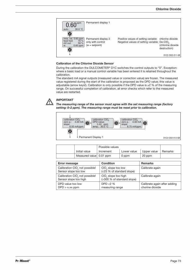
ProMinent® Page 73
Possible values
Initial value Increment Lower value Upper value Remarks
Measured value 0.01 ppm 0 ppm 20 ppm
Error message Condition Remarks
Calibration ClO2 not possible! ClO2 slope too low Calibrate again Sensor slope too low (<25 % of standard slope)
Calibration ClO2 not possible! ClO2 slope too high Calibrate again Sensor slope too high (>300 % of standard slope)
DPD value too low DPD <2 % Calibrate again after adding DPD > x.xx ppm measuring range chorine dioxide
calibration ClO2zero p.: 4.00 mAslope:
6.50 mA/ppm
calibration ClO2DPD-value:
0.60 ppmtemp.: 30.0 °C
calibration ClO2zero p.: 4.00 mAslope:
6.75 mA/ppm
Permanent Display 1 D1C2-CIO2-012-GB
Chlorine Dioxide
Calibration of the Chlorine Dioxide Sensor
During the calibration the DULCOMETER® D1C switches the control outputs to “0”. Exception: where a basic load or a manual control variable has been entered it is retained throughout the calibration. The standard mA signal outputs (measured value or correction value) are frozen. The measured value registered during the start of the calibration is proposed as the DPD value; this value is adjustable (arrow keys!). Calibration is only possible if the DPD value is ≥2 % of the measuring range. On successful completion of calibration, all error checks which refer to the measured value are restarted.
IMPORTANT
The measuring range of the sensor must agree with the set measuring range (factory setting: 0–2 ppm). The measuring range must be reset prior to calibration.
Positive values of setting variable: chlorine dioxideNegative values of setting variable: De-ClO2
(chlorine dioxidedestruction)
auto.: 30.0 °C
Permanent display 1
Permanent display 2only with control(w = setpoint)
ppm0.60
mea. val. 0.60 ppmfeed fwd: 70 %ctrl out: 59 %w: 0.60 ppm
D1C2-CIO2-011-GB
BA_DR_001_02_09_GB.indd 73BA_DR_001_02_09_GB.indd 73 24.02.2009 12:24:04 Uhr24.02.2009 12:24:04 Uhr
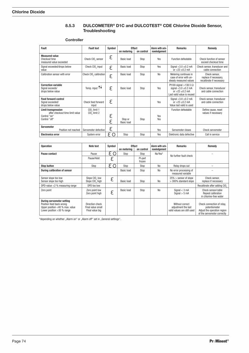
ProMinent®Page 74
8.5.3 DULCOMETER® D1C and DULCOTEST® CDE Chlorine Dioxide Sensor, Troubleshooting
Controller
Chlorine Dioxide
Operation Note text Symbol Effect Alarm with ack- Remarks Remedy on metering on control nowledgement
Pause contact Pause Stop Stop No/Yes* No further fault check
–
Pause/Hold PI-part frozen
Stop button Stop Stop Stop No Relay drops out –
During calibration of sensor Basic load Stop No No error processing of – measured variable
Sensor slope too low Slope ClO2 low 25% > sensor of slope Check sensor, Sensor slope too high Slope ClO2 high Basic load Stop No > 300% standard slope replace if necessary
DPD-value <2 % measuring range DPD too low Recalibrate after adding ClO2
Zero point Zero point low Basic load Stop No Signal < 3 mA Check sensor/cable Zero point high Signal > 5 mA Repeat calibration in chlorine-free water
During servomotor setting Position feed back wrong Direction check Without correct Check connection of relay, Upper position <40 % max. value Final value small adjustment the last potentiometer Lower position >30 % range Final value big valid values are still used Adjust the operation region of the servomotor correctly
*depending on whether „Alarm on“ or „Alarm off“ set in „General settings“.
Fault Fault text Symbol Effect Alarm with ack- Remarks Remedy on metering on control nowledgement
Measured value Checkout time Check ClO2 sensor Basic load Stop Yes Function defeatable Check function of sensor measured value exceeded exceed checkout time
Signal exceeded/drops below Check ClO2 input Basic load Stop Yes Signal <3.0 ±0.2 mA Check sensor, transducer and value or >23 ±0.2 mA cable connection
Calibration sensor with error Check ClO2 calibration Basic load Stop No Metering continues in Check sensor, case of error with un- replace if necessary, steady measured values recalibrate if necessary
Correction variable Pt100-signal >138.5 Ω Signal exceeds/ Temp. input Basic load Stop Yes signal <3.0 ±0.2 mA Check sensor, transducer drops below value or >23 ±0.2 mA and cable connection Last valid value is reused
Feed forward control Signal <3.8 ±0.2 mA Check sensor, transducer Signal exceeded/ Check feed forward Yes or >23 ±0.2 mA and cable connection drops below value input Value last valid is used
Limit transgression ClO2 limit 1 Function defeatable Defi ne cause, reset
after checkout time limit value ClO2 limit 2 values if necessary Control ”on“ Yes Control ”off“ Stop or Stop Yes Basic load
Servomotor Position not reached Servomotor defective Yes Servomotor closes Check servomotor
Electronics error System error Stop Stop Yes Elektronic data defective Call in service
BA_DR_001_02_09_GB.indd 74BA_DR_001_02_09_GB.indd 74 24.02.2009 12:24:04 Uhr24.02.2009 12:24:04 Uhr
ProMinent® Page 75
Chlorine Dioxide
Sensor: Troubleshooting
Fault
The sensor cannot be calibrated - meter/controller display value is greater than DPD-1 measurement
The sensor cannot be calibrated - meter/controller display value is smaller than DPD-1 measurement
Measuring value readout is “Zero”
Measuring value readout unstable
Possible cause
Run-in period too short
Diaphragm cap damaged
Interference from water con tam-inant
Short circuit in signal cable
DPD chemicals spent
Run-in period too short
Diaphragm cap deposits
Sample water fl ow inadequate
Air bubbles on the outside of the diaphragm
Reference electrode spent (shiny patches showing)
Surfactant in water (diaphragm is translucent)
No electrolyte in diaphragm cap
Electrolyte is penetrating sample water via gas bubbles
Interference from water con tam-inant
ClO2 content below the lower measuring range limit
Sensor incorrectly connected to controller
Air bubbles on the outside of the diaphragm
Diaphragm damaged
Cause lies with the controller
Remedy
� See “Run-in Period”
� Replace diaphragm cap. Run-in sensor, calibrate
� Identify interfering contaminant and implement remedy
� Identify short circuit and repair
� Use new DPD chemicals, repeat calibration
� See “Run-in Period”
� Remove deposits (see “Mainte-nance”). Replace diaphragm cap. Run-in sensor, calibrate
� Adjust fl ow rate
� Tap to remove air bubbles and increase fl ow if necessary
� Return sensor to ProMinent
� Remove surfactant and replace diaphragm cap. Run-in sensor, calibrate; use CDP sensor
� Add new electrolyte (see “Assembly”, “Run-in Period” and “Calibration”)
� Discuss with ProMinent
� Identify interfering contaminant and if necessary replace water
� Add ClO2 and then repeat calibration or use appropriate sensor
� Connect sensor correctly to controller
� Tap to remove air bubbles and increase fl ow if neccessary
� Replace diaphragm cap. Run-in sensor, calibrate
� Identify cause and remedy
BA_DR_001_02_09_GB.indd 75BA_DR_001_02_09_GB.indd 75 24.02.2009 12:24:04 Uhr24.02.2009 12:24:04 Uhr
ProMinent®Page 76
8.5.4 DULCOMETER® D1C Measured Variable Chlorine Dioxide and DULCOTEST® CDE Chlorine Dioxide Sensor, Maintenance
Controller
The DULCOMETER® controller type D1C for the measured variable chlorine dioxide is mainte-nance-free.
Sensor
IMPORTANT
• The sensor must be regularly serviced in order to avoid overdosing due to sensor failure!
• Observe applicable national directives for servicing intervals!
• Do not touch the electrodes or bring them into contact with greasy substances!
Maintenance interval Daily/weekly servicing intervals depending upon application.
Maintenance Work
� Check the sensor display value at the controller using an appropriate chlorine dioxide meas uring system (e.g. DPD-1).
� Recalibrate the sensor if necessary
Cleaning the Membrane
If the membrane is dirty and is preventing calibration of the sensor you can try to clean the membrane gently.
First dismantle the sensor as described in the sensor dismantling section. Observe safety guidelines! Removal of surface contamination
� Rinse the membrane under a gentle stream of cold water.
Removal of Lime Deposits
� Place the membrane cap in 1 % hydrochloric acid (e. g. overnight).
� Rinse the membrane cap with plenty of water.
Now fi ll the sensor with electrolyte, run in and recalibrate.
Replace the Membrane
If calibration is no longer possible after cleaning the membrane, or if the membrane is damaged it must be replaced.
Chlorine Dioxide
BA_DR_001_02_09_GB.indd 76BA_DR_001_02_09_GB.indd 76 24.02.2009 12:24:04 Uhr24.02.2009 12:24:04 Uhr

ProMinent® Page 77
Chlorite
8.6 Measuring Parameter Chlorite
8.6.1 DULCOMETER® D1C Measured Variable Chlorite, Setting and Operation
Display Symbols The display of the DULCOMETER® D1C controller uses the following symbols:
Description Comment Symbol
Limit value transgression Symbol Relay 1, upper left
Symbol Relay 1, lower left
Symbol Relay 2, upper right
Symbol Relay 2, lower right
Metering pump 1 (chlorite) Symbol Control off left
Symbol Control on left
Metering pump 2 (De-Clt) Symbol Control off right
Symbol Control on right
Solenoid valve 1 (chlorite) Symbol Control off left
Symbol Control on left
Solenoid valve 2 (De-Clt) Symbol Control off right
Symbol Control on right
Servomotor Control, open relay
Control, close relay
Without control
Thickness of bar Position feedback increases from left to right during opening
Stop button pressed
Manual metering
Fault
BA_DR_001_02_09_GB.indd 77BA_DR_001_02_09_GB.indd 77 24.02.2009 12:24:04 Uhr24.02.2009 12:24:04 Uhr
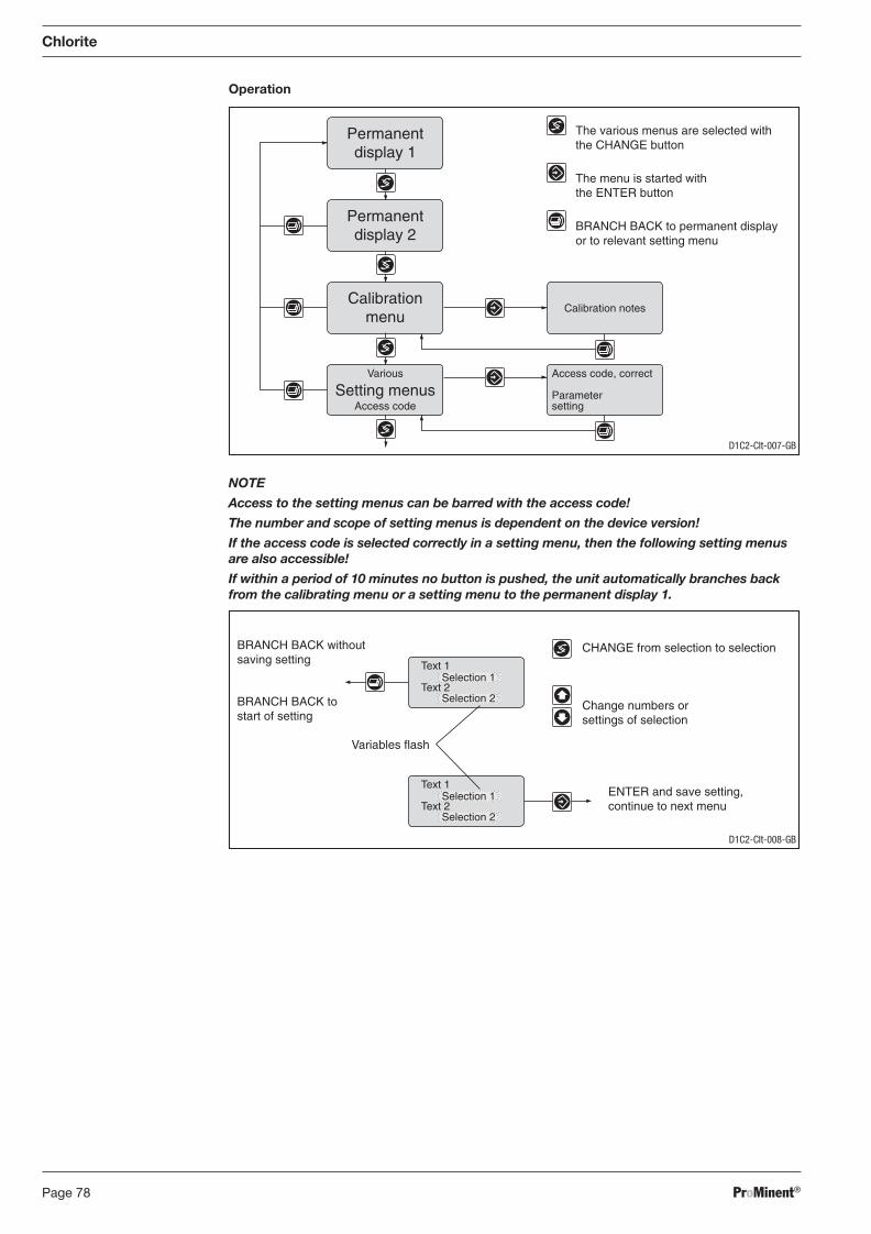
ProMinent®Page 78
Chlorite
Operation
NOTE
Access to the setting menus can be barred with the access code!
The number and scope of setting menus is dependent on the device version!
If the access code is selected correctly in a setting menu, then the following setting menus are also accessible!
If within a period of 10 minutes no button is pushed, the unit automatically branches back from the calibrating menu or a setting menu to the permanent display 1.
Access code, correct
Parametersetting
Calibration notes
Permanentdisplay 1
Permanentdisplay 2
Calibrationmenu
Various
Access codeSetting menus
The various menus are selected withthe CHANGE button
The menu is started withthe ENTER button
BRANCH BACK to permanent displayor to relevant setting menu
D1C2-Clt-007-GB
CHANGE from selection to selection
Change numbers orsettings of selection
Variables flash
ENTER and save setting,continue to next menu
BRANCH BACK withoutsaving setting
BRANCH BACK tostart of setting
Text 1
Text 2Selection 1
Selection 2
Text 1
Text 2Selection 1
Selection 2
D1C2-Clt-008-GB
BA_DR_001_02_09_GB.indd 78BA_DR_001_02_09_GB.indd 78 24.02.2009 12:24:04 Uhr24.02.2009 12:24:04 Uhr
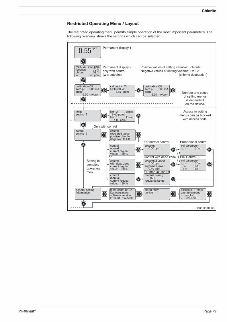
ProMinent® Page 79
Positive values of setting variable: chloriteNegative values of setting variable: De-Clt
(chlorite destruction)
Permanent display 1
Permanent display 2only with control(w = setpoint)
Control with dead zone
For normal control
PID Control
Proportional control
Only with control
ppm0.55
mea. val 0.55 ppmfeedfwd: 70 %ctrlout: 59 %w: 0.40 ppm
calibration Cltzero p.: 0.00 mAslope
6.50 mA/ppm
calibration CltDPD-value:
1.55 ppm
calibration Cltzero p.: 0.00 mAslope
6.50 mA/ppm
limitssetting ?
limit 2 upper5.00 ppm
limit 1 lower1.00 ppm
controlsetting ?
controlnormalcurrent regulat.value: 30 %
setpoint0.50 ppm
ctrl parameterxp = 10 %
controlwith dead zonecurrent regulat.value: 30 %
setpoint 2 upper0.50 ppm
setpoint 1 lower0.40 ppm
controlmanualcurrent regulat.value: 30 %
manual dosing15 %
regulated range
general settinginformation
ident-code: D1CADxIxxxxxxxxxxsoftware versionD1C-B1 FW-5.00
alarm relay active
access c.: 5000operating menu:= english= reduced
Number and scopeof setting menus
is dependenton the device.
Access to settingmenus can be blocked
with access code.
ctrl parameterxp = 10 %Ti = offTd = off
For manual control
or
or
Setting incompleteoperatingmenu
controlregulated valuepositive chloritenegative De-Clt
Restricted Operating Menu / Layout
The restricted operating menu permits simple operation of the most important parameters. The following overview shows the settings which can be selected:
Chlorite
D1C2-Clt-010-GB
BA_DR_001_02_09_GB.indd 79BA_DR_001_02_09_GB.indd 79 24.02.2009 12:24:04 Uhr24.02.2009 12:24:04 Uhr
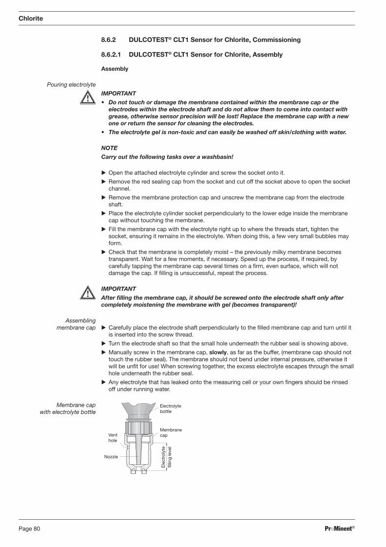
ProMinent®Page 80
Chlorite
8.6.2 DULCOTEST® CLT1 Sensor for Chlorite, Commissioning
8.6.2.1 DULCOTEST® CLT1 Sensor for Chlorite, Assembly
Assembly
Pouring electrolyte
IMPORTANT
• Do not touch or damage the membrane contained within the mem brane cap or the electrodes within the electrode shaft and do not allow them to come into contact with grease, otherwise sensor precision will be lost! Replace the membrane cap with a new one or return the sensor for cleaning the electrodes.
• The electrolyte gel is non-toxic and can easily be washed off skin/clothing with water.
NOTE
Carry out the following tasks over a washbasin!
� Open the attached electrolyte cylinder and screw the socket onto it.
� Remove the red sealing cap from the socket and cut off the socket above to open the socket channel.
� Remove the membrane protection cap and unscrew the membrane cap from the electrode shaft.
� Place the electrolyte cylinder socket perpendicularly to the lower edge inside the membrane cap without touching the membrane.
� Fill the membrane cap with the electrolyte right up to where the threads start, tighten the socket, ensuring it remains in the electrolyte. When doing this, a few very small bubbles may form.
� Check that the membrane is completely moist – the previously milky mem brane becomes transparent. Wait for a few moments, if necessary. Speed up the process, if required, by carefully tapping the membrane cap several times on a fi rm, even surface, which will not damage the cap. If fi lling is unsuccessful, repeat the process.
IMPORTANT
After fi lling the membrane cap, it should be screwed onto the electrode shaft only after completely moistening the membrane with gel (be comes transparent)!
Assembling membrane cap � Carefully place the electrode shaft perpendicularly to the fi lled membrane cap and turn until it
is inserted into the screw thread.
� Turn the electrode shaft so that the small hole underneath the rubber seal is showing above.
� Manually screw in the membrane cap, slowly, as far as the buffer, (mem brane cap should not touch the rubber seal). The membrane should not bend under internal pressure, otherwise it will be unfi t for use! When screwing together, the excess electrolyte escapes through the small hole underneath the rubber seal.
� Any electrolyte that has leaked onto the measuring cell or your own fi ngers should be rinsed off under running water.
Membrane cap with electrolyte bottle
Ele
ctro
lyte
fi l
ling
leve
l
Membrane cap Vent
hole
Electrolyte bottle
Nozzle
BA_DR_001_02_09_GB.indd 80BA_DR_001_02_09_GB.indd 80 24.02.2009 12:24:05 Uhr24.02.2009 12:24:05 Uhr
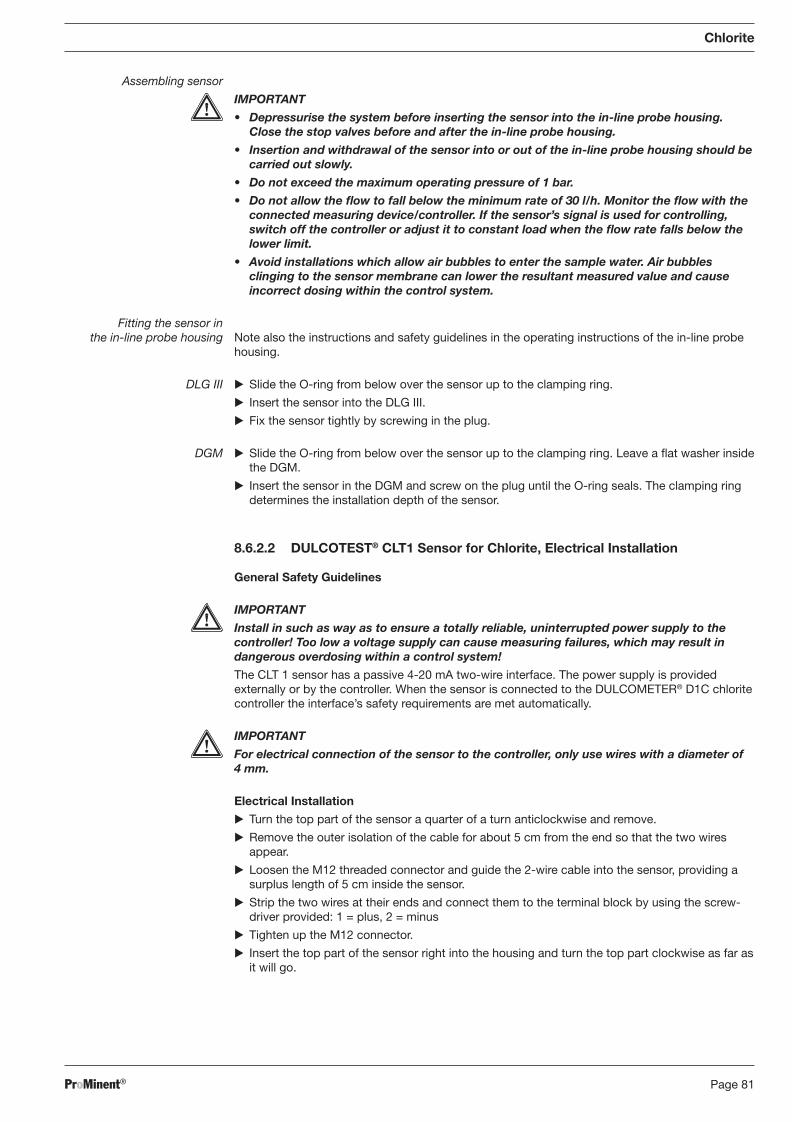
ProMinent® Page 81
Assembling sensor
IMPORTANT
• Depressurise the system before inserting the sensor into the in-line probe housing. Close the stop valves before and after the in-line probe housing.
• Insertion and withdrawal of the sensor into or out of the in-line probe housing should be carried out slowly.
• Do not exceed the maximum operating pressure of 1 bar.
• Do not allow the fl ow to fall below the minimum rate of 30 l/h. Monitor the fl ow with the connected measuring device/controller. If the sensor’s signal is used for controlling, switch off the controller or adjust it to constant load when the fl ow rate falls below the lower limit.
• Avoid installations which allow air bubbles to enter the sample water. Air bubbles clinging to the sensor membrane can lower the resultant measured value and cause incorrect dosing within the control system.
Fitting the sensor in the in-line probe housing Note also the instructions and safety guidelines in the operating instructions of the in-line probe
housing.
DLG III � Slide the O-ring from below over the sensor up to the clamping ring.
� Insert the sensor into the DLG III.
� Fix the sensor tightly by screwing in the plug.
DGM � Slide the O-ring from below over the sensor up to the clamping ring. Leave a fl at washer inside the DGM.
� Insert the sensor in the DGM and screw on the plug until the O-ring seals. The clamping ring determines the installation depth of the sensor.
8.6.2.2 DULCOTEST® CLT1 Sensor for Chlorite, Electrical Installation
General Safety Guidelines
IMPORTANT
Install in such as way as to ensure a totally reliable, uninterrupted power supply to the controller! Too low a voltage supply can cause measuring failures, which may result in dangerous overdosing within a control system!
The CLT 1 sensor has a passive 4-20 mA two-wire interface. The power supply is provided externally or by the controller. When the sensor is connected to the DULCOMETER® D1C chlorite controller the interface’s safety require ments are met automatically.
IMPORTANT
For electrical connection of the sensor to the controller, only use wires with a diameter of 4 mm.
Electrical Installation
� Turn the top part of the sensor a quarter of a turn anticlockwise and remove.
� Remove the outer isolation of the cable for about 5 cm from the end so that the two wires appear.
� Loosen the M12 threaded connector and guide the 2-wire cable into the sensor, providing a surplus length of 5 cm inside the sensor.
� Strip the two wires at their ends and connect them to the terminal block by using the screw-driver provided: 1 = plus, 2 = minus
� Tighten up the M12 connector.
� Insert the top part of the sensor right into the housing and turn the top part clockwise as far as it will go.
Chlorite
BA_DR_001_02_09_GB.indd 81BA_DR_001_02_09_GB.indd 81 24.02.2009 12:24:05 Uhr24.02.2009 12:24:05 Uhr
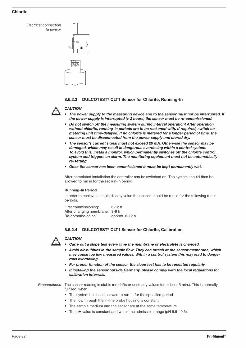
ProMinent®Page 82
Chlorite
Electrical connection to sensor
1 2
5 cm
8.6.2.3 DULCOTEST® CLT1 Sensor for Chlorite, Running-In
CAUTION
• The power supply to the measuring device and to the sensor must not be interrupted. If the power supply is interrupted (> 2 hours) the sensor must be re-commis sioned.
• Do not switch off the measuring system during interval operation! After operation without chlorite, running-in periods are to be reckoned with. If required, switch on metering unit time-delayed! If no chlorite is metered for a longer period of time, the sensor must be disconnected from the power supply and stored dry.
• The sensor’s current signal must not exceed 20 mA. Otherwise the sensor may be damaged, which may result in dangerous overdosing within a control system. To avoid this, install a monitor, which permanently switches off the chlorite control system and triggers an alarm. The monitoring equipment must not be automatically re-setting.
• Once the sensor has been commissioned it must be kept permanently wet.
After completed installation the controller can be switched on. The system should then be allowed to run in for the set run-in period.
Running-In Period
In order to achieve a stable display value the sensor should be run in for the following run in periods.
First commissioning: 6-12 h After changing membrane: 3-6 h Re-commissioning: approx. 6-12 h
8.6.2.4 DULCOTEST® CLT1 Sensor for Chlorite, Calibration
CAUTION
• Carry out a slope test every time the membrane or electrolyte is changed.
• Avoid air-bubbles in the sample fl ow. They can attach at the sensor mem brane, which may cause too low measured values. Within a control system this may lead to dange-rous over dosing.
• For proper function of the sensor, the slope test has to be repeated regularly.
• If installing the sensor outside Germany, please comply with the local regulations for calibration intervals.
Preconditions The sensor reading is stable (no drifts or unsteady values for at least 5 min.). This is normally fulfi lled, when
• The system has been allowed to run-in for the specifi ed period
• The fl ow through the in-line probe housing is constant
• The sample medium and the sensor are at the same temperature
• The pH value is constant and within the admissible range (pH 6.5 - 9.5).
BA_DR_001_02_09_GB.indd 82BA_DR_001_02_09_GB.indd 82 24.02.2009 12:24:05 Uhr24.02.2009 12:24:05 Uhr
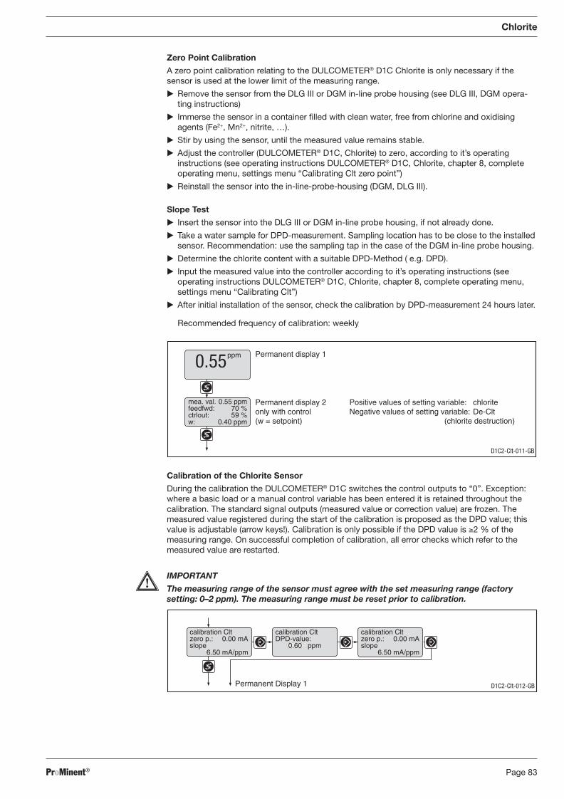
ProMinent® Page 83
Chlorite
Zero Point Calibration
A zero point calibration relating to the DULCOMETER® D1C Chlorite is only necessary if the sensor is used at the lower limit of the measuring range.
� Remove the sensor from the DLG III or DGM in-line probe housing (see DLG III, DGM opera-ting instructions)
� Immerse the sensor in a container fi lled with clean water, free from chlorine and oxidising agents (Fe2+, Mn2+, nitrite, …).
� Stir by using the sensor, until the measured value remains stable.
� Adjust the controller (DULCOMETER® D1C, Chlorite) to zero, according to it’s operating instructions (see operating instructions DULCOMETER® D1C, Chlorite, chapter 8, complete operating menu, settings menu “Cali brating Clt zero point”)
� Reinstall the sensor into the in-line-probe-housing (DGM, DLG III).
Slope Test
� Insert the sensor into the DLG III or DGM in-line probe housing, if not already done.
� Take a water sample for DPD-measurement. Sampling location has to be close to the installed sensor. Recommendation: use the sampling tap in the case of the DGM in-line probe housing.
� Determine the chlorite content with a suitable DPD-Method ( e.g. DPD).
� Input the measured value into the controller according to it’s operating instructions (see operating instructions DULCOMETER® D1C, Chlorite, chapter 8, complete operating menu, settings menu “Calibrating Clt”)
� After initial installation of the sensor, check the calibration by DPD-measurement 24 hours later.
Recommended frequency of calibration: weekly
Calibration of the Chlorite Sensor
During the calibration the DULCOMETER® D1C switches the control outputs to “0”. Exception: where a basic load or a manual control variable has been entered it is retained throughout the calibration. The standard signal outputs (measured value or correction value) are frozen. The measured value registered during the start of the calibration is proposed as the DPD value; this value is adjustable (arrow keys!). Calibration is only possible if the DPD value is ≥2 % of the measuring range. On successful completion of calibration, all error checks which refer to the measured value are restarted.
IMPORTANT
The measuring range of the sensor must agree with the set measuring range (factory setting: 0–2 ppm). The measuring range must be reset prior to calibration.
Permanent display 1
Permanent display 2only with control(w = setpoint)
ppm0.55
mea. val. 0.55 ppmfeedfwd: 70 %ctrlout: 59 %w: 0.40 ppm
Positive values of setting variable: chloriteNegative values of setting variable: De-Clt
(chlorite destruction)
D1C2-Clt-011-GB
Permanent Display 1
calibration Cltzero p.: 0.00 mAslope
6.50 mA/ppm
calibration Cltzero p.: 0.00 mAslope
6.50 mA/ppm
calibration CltDPD-value:
0.60 ppm
D1C2-Clt-012-GB
BA_DR_001_02_09_GB.indd 83BA_DR_001_02_09_GB.indd 83 24.02.2009 12:24:05 Uhr24.02.2009 12:24:05 Uhr
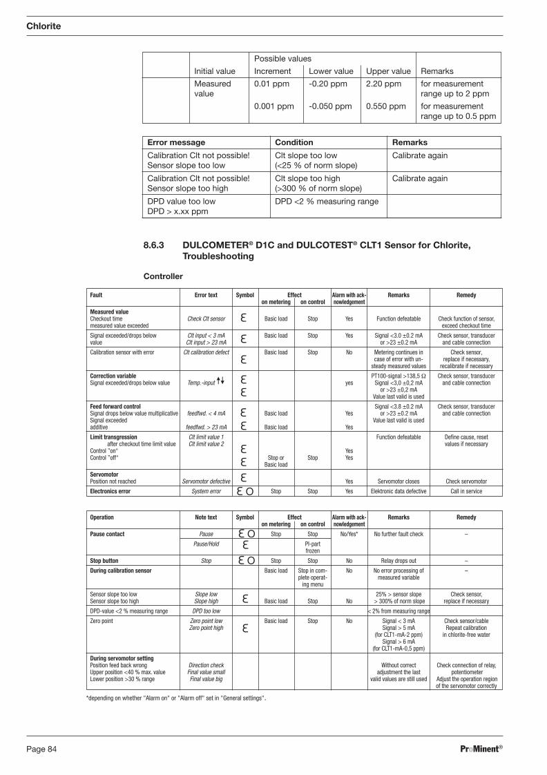
ProMinent®Page 84
Operation Note text Symbol Effect Alarm with ack- Remarks Remedy on metering on control nowledgement
Pause contact Pause Stop Stop No/Yes* No further fault check –
Pause/Hold PI-part frozen
Stop button Stop Stop Stop No Relay drops out –
During calibration sensor Basic load Stop in com- No No error processing of – plete operat- measured variable ing menu
Sensor slope too low Slope low 25% > sensor slope Check sensor, Sensor slope too high Slope high Basic load Stop No > 300% of norm slope replace if necessary
DPD-value <2 % measuring range DPD too low < 2% from measuring range
Zero point Zero point low Basic load Stop No Signal < 3 mA Check sensor/cable Zero point high Signal > 5 mA Repeat calibration (for CLT1-mA-2 ppm) in chlorite-free water Signal > 6 mA (for CLT1-mA-0,5 ppm)
During servomotor setting Position feed back wrong Direction check Without correct Check connection of relay, Upper position <40 % max. value Final value small adjustment the last potentiometer Lower position >30 % range Final value big valid values are still used Adjust the operation region of the servomotor correctly
Fault Error text Symbol Effect Alarm with ack- Remarks Remedy on metering on control nowledgement
Measured value Checkout time Check Clt sensor Basic load Stop Yes Function defeatable Check function of sensor, measured value exceeded exceed checkout time
Signal exceeded/drops below Clt input < 3 mA Basic load Stop Yes Signal <3.0 ±0.2 mA Check sensor, transducer value Clt input > 23 mA or >23 ±0.2 mA and cable connection
Calibration sensor with error Clt calibration defect Basic load Stop No Metering continues in Check sensor, case of error with un- replace if necessary, steady measured values recalibrate if necessary
Correction variable PT100-signal >138,5 Ω Check sensor, transducer Signal exceeded/drops below value Temp.-input yes Signal <3,0 ±0,2 mA and cable connection or >23 ±0,2 mA Value last valid is used
Feed forward control Signal <3.8 ±0.2 mA Check sensor, transducer Signal drops below value multiplicative feedfwd. < 4 mA Basic load Yes or >23 ±0.2 mA and cable connection Signal exceeded Value last valid is used additive feedfwd. > 23 mA Basic load Yes
Limit transgression Clt limit value 1 Function defeatable Defi ne cause, reset after checkout time limit value Clt limit value 2 values if necessary Control ”on“ Yes Control ”off“ Stop or Stop Yes Basic load
Servomotor Position not reached Servomotor defective Yes Servomotor closes Check servomotor
Electronics error System error Stop Stop Yes Elektronic data defective Call in service
Chlorite
8.6.3 DULCOMETER® D1C and DULCOTEST® CLT1 Sensor for Chlorite, Troubleshooting
Controller
Error message Condition Remarks
Calibration Clt not possible! Clt slope too low Calibrate again Sensor slope too low (<25 % of norm slope)
Calibration Clt not possible! Clt slope too high Calibrate again Sensor slope too high (>300 % of norm slope)
DPD value too low DPD <2 % measuring range DPD > x.xx ppm
Possible values
Initial value Increment Lower value Upper value Remarks
Measured 0.01 ppm -0.20 ppm 2.20 ppm for measurement value range up to 2 ppm
0.001 ppm -0.050 ppm 0.550 ppm for measurement range up to 0.5 ppm
*depending on whether "Alarm on" or "Alarm off" set in "General settings".
BA_DR_001_02_09_GB.indd 84BA_DR_001_02_09_GB.indd 84 24.02.2009 12:24:05 Uhr24.02.2009 12:24:05 Uhr
ProMinent® Page 85
Sensor: Troubleshooting
Troubleshooting must take account of the whole measuring system. The measuring system consists of:
1) Measurement/control device 2) Electrical leads and connectors 3) In-line probe housing and hydraulic connections 4) Sensor
The possible causes of failure listed in the following table primarily refer to the sensor. Before commencing troubleshooting please ensure that the operating conditions in “Technical data” are met:
a) Chlorite content 0.1 - 2 mg/l resp. 0.02 - 0.5 mg/l b) Constant pH in the range 6.5 - 9.5 c) Temperature 1 - 40 °C, no sudden rises in temperature d) Conductivity: 0.05 - 5 mS/cm e) Flow: 30 - 60 l/h
The sensor simulator (DULCOMETER® Simulator order no. 1004042) is recommended for locating a controller malfunction. You will fi nd a detailed description of troubleshooting of the controller in the operating instructions of DULCOMETER® D1C, Chlorite.
If the value measured by the sensor differs signifi cantly from that of the DPD method you need to fi rst consider all possible malfunctions of the DPD photo metric method. If necessary, repeat the DPD measurement several times.
Chlorite
Fault
Sensor can not be calibrated and meas-ured value greater than DPD-measurement
Sensor can not be calibrated and meas-ured value smaller than DPD-measurement
Possible Cause
Run-in time too short
Membrane cap damaged
Interfering substances in sample water
Short-circuit in signal lead
Distance between working electrode and membrane too great
DPD chemicals spent
Run-in time too short
Built-up of deposits on membrane cap
Flow rate of sample water too low
Air bubbles on the outside of the membrane
Interfering substances in sample water (surfactants, oil, alcohols, corrosion inhibitors)
Deposits (carbonate, manganese, iron oxide) have blocked membrane
pH-value > pH 9.5
No electrolyte present in membrane cap
Remedy
� See “Run-in period”
� Replace membrane cap, run in sensor and calibrate
� Examine sample water for interfering substances and remedy
� Locate and eliminate short circuit
� Screw the membrane cap tightly onto the electrode shaft
� Use new DPD chemicals, repeat calibration
� See “Run-in period”
� Clean membrane cap resp. replace, run-in the sensor, calibrate
� Adjust fl ow rate
� Tap to remove air bubbles and increase fl ow if necessary
� Confer with ProMinent
� Replace membrane cap run-in sensor, calibrate
� Lower the pH value (pH 6.5-pH 9.5)
� Fill membrane cap with new electrolyte (see “Assembly”, “Run-in period” and “Cali bra-tion”)
BA_DR_001_02_09_GB.indd 85BA_DR_001_02_09_GB.indd 85 24.02.2009 12:24:05 Uhr24.02.2009 12:24:05 Uhr
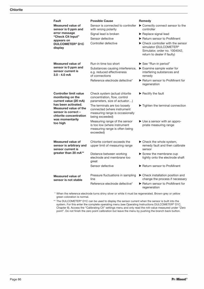
ProMinent®Page 86
Chlorite
Fault Possible Cause Remedy
Measured value of sensor is 0 ppm and error message “Check Clt Input” appears on DULCOMETER® D1C display
Measured value of sensor is 0 ppm and sensor current is 3.0 - 4.0 mA
Controller limit value monitoring on the current value (20 mA) has been activated. Measured value of the sensor is correct – chlorite concentration was momentarily too high
Measured value of sensor is arbitrary and sensor current is greater than 20 mA**
Measured value of sensor is not stable
Sensor is connected to controller with wrong polarity
Signal lead is broken
Sensor defective
Controller defective
Run-in time too short
Substances causing interference, e.g. reduced effectiveness of connections
Reference electrode defective*
Check system (actual chlorite concentration, fl ow, control parameters, size of actuator…)
The terminals are too loosely connected (where instrument measuring range is occasionally being exceeded)
Measuring range of the sensor is too low (where instrument meas uring range is often being exceeded)
Chlorite content exceeds the upper limit of measuring range
Distance between working electrode and membrane too great
Sensor defective
Pressure fl uctuations in sampling line
Reference electrode defective*
� Correctly connect sensor to the controller
� Replace signal lead
� Return sensor to ProMinent
� Check controller with the sensor simulator (DULCOMETER® Simulator, order no. 1004042, return to dealer if faulty)
� See “Run-in period”
� Examine sample water for interfering substances and remedy
� Return sensor to ProMinent for regeneration
� Rectify the fault
� Tighten the terminal connection
� Use a sensor with an appro-priate measuring range
� Check the whole system, remedy fault and then calibrate sensor
� Screw the membrane cup tightly onto the electrode shaft
� Return sensor to ProMinent
� Check installation position and change the process if necessary
� Return sensor to ProMinent for regeneration
* When the reference electrode turns shiny silver or white it must be regenerated. Brown-grey or yellow green coloration is normal.
** The DULCOMETER® D1C can be used to display the sensor current when the sensor is built into the system. For this enter the complete operating menu (see Operating Instructions DULCOMETER® D1C, Chapter 8). Access the “Calibrating Clt” settings menu and only read the mA-value measured under “Zero point”. Do not fi nish the zero point calibration but leave the menu by pushing the branch back button.
BA_DR_001_02_09_GB.indd 86BA_DR_001_02_09_GB.indd 86 24.02.2009 12:24:05 Uhr24.02.2009 12:24:05 Uhr
ProMinent® Page 87
Chlorite
8.6.4 DULCOMETER® D1C Measured Variable Chlorite and DULCOTEST® CLT1 Sensor for Chlorite, Maintenance
Controller
The DULCOMETER® controller type D1C for the measured variable chlorite is maintenance-free.
Sensor
IMPORTANT
• Service the sensor regularly to avoid overdosing within a control system, due to in cor-rect measured value.
• Observe the current national regulations for maintenance intervals.
• Do not touch the electrodes or allow them to come into contact with greasy substances.
• Never attempt to clean the membrane with acid/alkaline solutions, cleaning reagents or mechanical aids (brushes or similar).
Maintenance interval weekly (recommended)
Maintenance Work
� Check the sensor regularly for dirt, algae and air bubbles. As far as pos si ble, avoid contamina-tion of the membrane with solid particles, deposits etc. Eliminate air bubbles by increasing the fl ow rate.
� Check the sensor’s reading on the controller regularly, using an appropriate instrument for measuring bromine (e.g. DPD).
� If necessary, recalibrate the sensor.
� If calibration cannot be carried out properly, the membrane cap must be replaced and calibra-tion must be repeated.
BA_DR_001_02_09_GB.indd 87BA_DR_001_02_09_GB.indd 87 24.02.2009 12:24:05 Uhr24.02.2009 12:24:05 Uhr
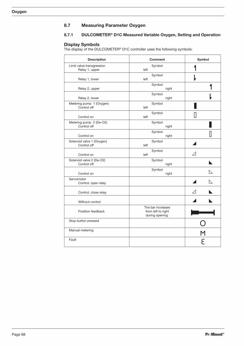
ProMinent®Page 88
Oxygen
8.7 Measuring Parameter Oxygen
8.7.1 DULCOMETER® D1C Measured Variable Oxygen, Setting and Operation
Display Symbols The display of the DULCOMETER® D1C controller uses the following symbols:
Description Comment Symbol
Limit value transgression Symbol Relay 1, upper left
Symbol Relay 1, lower left
Symbol Relay 2, upper right
Symbol Relay 2, lower right
Metering pump 1 (Oxygen) Symbol Control off left
Symbol Control on left
Metering pump 2 (De-O2) Symbol Control off right
Symbol Control on right
Solenoid valve 1 (Oxygen) Symbol Control off left
Symbol Control on left
Solenoid valve 2 (De-O2) Symbol Control off right
Symbol Control on right
Servomotor Control, open relay
Control, close relay
Without control
The bar increases Position feedback from left to right during opening.
Stop button pressed
Manual metering
Fault
BA_DR_001_02_09_GB.indd 88BA_DR_001_02_09_GB.indd 88 24.02.2009 12:24:05 Uhr24.02.2009 12:24:05 Uhr
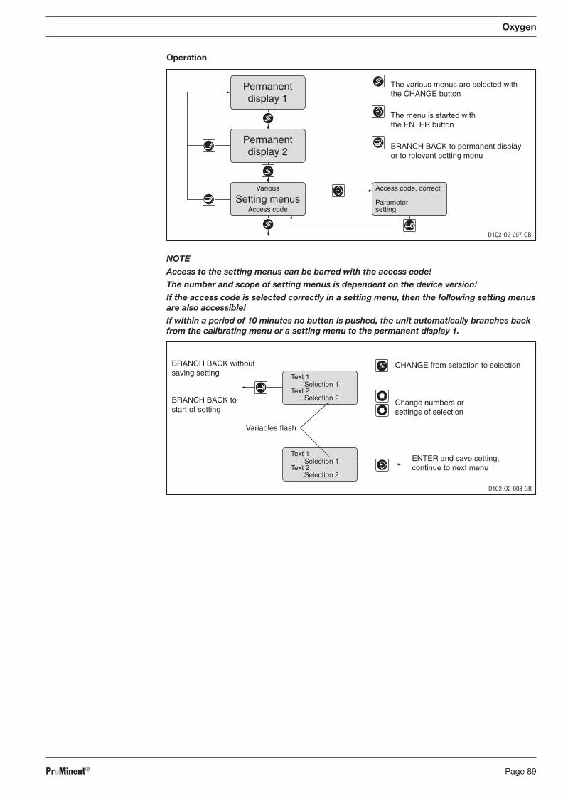
ProMinent® Page 89
Oxygen
Operation
NOTE
Access to the setting menus can be barred with the access code!
The number and scope of setting menus is dependent on the device version!
If the access code is selected correctly in a setting menu, then the following setting menus are also accessible!
If within a period of 10 minutes no button is pushed, the unit automatically branches back from the calibrating menu or a setting menu to the permanent display 1.
D1C2-O2-007-GB
Access code, correct
Parametersetting
Permanentdisplay 1
Permanentdisplay 2
Various
Access codeSetting menus
The various menus are selected withthe CHANGE button
The menu is started withthe ENTER button
BRANCH BACK to permanent displayor to relevant setting menu
D1C2-O2-008-GB
CHANGE from selection to selection
Change numbers orsettings of selection
Variables flash
ENTER and save setting,continue to next menu
BRANCH BACK withoutsaving setting
BRANCH BACK tostart of setting
Text 1
Text 2Selection 1
Selection 2
Text 1
Text 2Selection 1
Selection 2
BA_DR_001_02_09_GB.indd 89BA_DR_001_02_09_GB.indd 89 24.02.2009 12:24:05 Uhr24.02.2009 12:24:05 Uhr
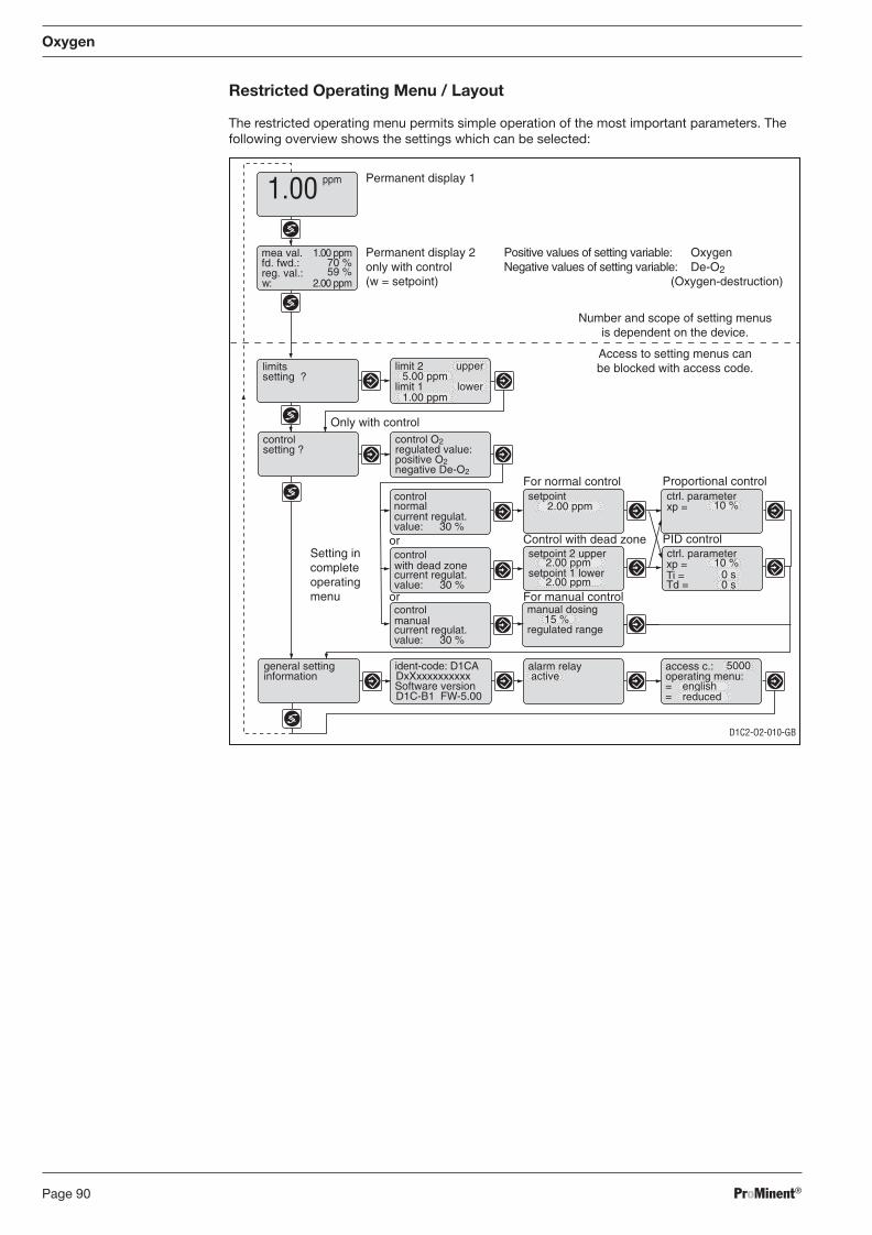
ProMinent®Page 90
Oxygen
Restricted Operating Menu / Layout
The restricted operating menu permits simple operation of the most important parameters. The following overview shows the settings which can be selected:
Number and scope of setting menusis dependent on the device.
Access to setting menus canbe blocked with access code.
D1C2-O2-010-GB
Permanent display 1
w:
70 %59 %
2.00 ppm
Ti =Td =
xp =
0 s
10 %
xp = 10 %
15 %
DxXxxxxxxxxxx
D1C-B1 FW-5.00==
5000
2.00 ppm
2.00 ppm
mea val. Permanent display 2only with control(w = setpoint)
fd. fwd.:reg. val.:
Positive values of setting variable:Negative values of setting variable:
limitssetting ?
controlsetting ?
Only with controlcontrol O2
positive O2regulated value:
negative De-O2
Control with dead zone
For normal control
PID control
Proportional controlsetpoint
setpoint 2 upper ctrl. parameter
setpoint 1 lower
ctrl. parameter
manual dosing
regulated range
general settinginformation
ident-code: D1CA
Software version
alarm relay access c.:operating menu:active
english
1.00 ppm
2.00 ppm
ppm1.00
Oxygen De-O2(Oxygen-destruction)
control
current regulat.value: 30 %
with dead zone
control
current regulat.value: 30 %
manual
control
current regulat.value: 30 %
normal
Setting incompleteoperatingmenu
0 s
or
or
limit 2 upper
limit 1 lower1.00 ppm
5.00 ppm
reduced
For manual control
BA_DR_001_02_09_GB.indd 90BA_DR_001_02_09_GB.indd 90 24.02.2009 12:24:05 Uhr24.02.2009 12:24:05 Uhr
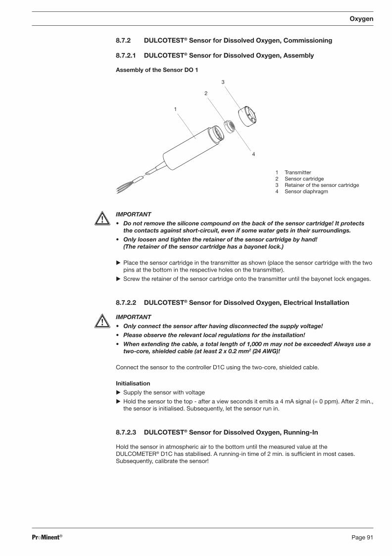
ProMinent® Page 91
8.7.2 DULCOTEST® Sensor for Dissolved Oxygen, Commissioning
8.7.2.1 DULCOTEST® Sensor for Dissolved Oxygen, Assembly
Assembly of the Sensor DO 1
Oxygen
IMPORTANT
• Do not remove the silicone compound on the back of the sensor cartridge! It protects the contacts against short-circuit, even if some water gets in their surroundings.
• Only loosen and tighten the retainer of the sensor cartridge by hand! (The retainer of the sensor cartridge has a bayonet lock.)
� Place the sensor cartridge in the transmitter as shown (place the sensor cartridge with the two pins at the bottom in the respective holes on the transmitter).
� Screw the retainer of the sensor cartridge onto the transmitter until the bayonet lock engages.
8.7.2.2 DULCOTEST® Sensor for Dissolved Oxygen, Electrical Installation
IMPORTANT
• Only connect the sensor after having disconnected the supply voltage!
• Please observe the relevant local regulations for the installation!
• When extending the cable, a total length of 1,000 m may not be exceeded! Always use a two-core, shielded cable (at least 2 x 0.2 mm2 (24 AWG)!
Connect the sensor to the controller D1C using the two-core, shielded cable.
Initialisation
� Supply the sensor with voltage
� Hold the sensor to the top - after a view seconds it emits a 4 mA signal (= 0 ppm). After 2 min., the sensor is initialised. Subsequently, let the sensor run in.
8.7.2.3 DULCOTEST® Sensor for Dissolved Oxygen, Running-In
Hold the sensor in atmospheric air to the bottom until the measured value at the DULCOMETER® D1C has stabilised. A running-in time of 2 min. is suffi cient in most cases. Subsequently, calibrate the sensor!
1 Transmitter2 Sensor cartridge3 Retainer of the sensor cartridge4 Sensor diaphragm
4
1
2
3
BA_DR_001_02_09_GB.indd 91BA_DR_001_02_09_GB.indd 91 24.02.2009 12:24:05 Uhr24.02.2009 12:24:05 Uhr
ProMinent®Page 92
Oxygen
8.7.2.4 DULCOTEST® Sensor for Dissolved Oxygen, Calibration
IMPORTANT
• The sensor should not be subjected to direct sunlight or other heat source during calibration. This will prevent temperature compensation.
• The sensor is calibrated in the normal atmosphere (oxygen content = 20.9 vol. %).
• Observe relevant national legislation when calibrating, e.g. in Germany EN 25814.
NOTE
• Do not calibrate the sensor with a DULCOMETER® D1C controller for longer than 10 min. The D1C will otherwise display an error (error text “O2 input ≤ 4 mA”).
• If you cancel the calibration within 3 min. the sensor will continue to operate with the previous calibration values.
� Clean the sensor.
� Check whether the DULCOMETER® D1C displays a stable value in the normal atmosphere.
� Hold the sensor up in the atmosphere to calibrate. The sensor will emit a 4 mA signal through-out this phase and the DULCOMETER® D1C will display “0” ppm. In the calibration menu of the DULCOMETER® D1C, chap. 8, “Calibrating the O2 sensor up”, the remaining calibration time is counted down.
� After approx. 5 min. lower the sensor again. Calibration is now complete. The sensor will start to measure again.
Calibrate the sensor every six months or more frequently if the application requires it.
Infl uences on the measured variable The integrated temperature sensor compensates temperature infl uences on the measured
variable.
To minimise the effect of the following parameters on the accuracy of the measured values you can enter actual values in the DULCOMETER® D1C “Measurement parameters setting?” menu during calibration and in the interim period (see operating instructions manual for DULCOMETER® D1C, measured variable oxygen, part 2):
- Local atmospheric pressure at the measuring point related to the height above sea level in mbar
- Height of measurement point above sea level in m - Relative humidity of the atmosphere at the measuring point in % - Air temperature at the measuring point in °C - Water temperature in °C - Water salt content in g/l
The “Factory settings” table in the Appendix of the individual operating instructions of the sensors gives the infl uence of these parameters on the measured value where these deviate from the set values.
The table also shows how to determine the parameters.
BA_DR_001_02_09_GB.indd 92BA_DR_001_02_09_GB.indd 92 24.02.2009 12:24:05 Uhr24.02.2009 12:24:05 Uhr
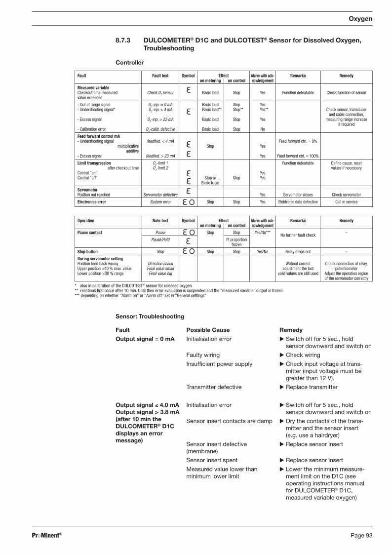
ProMinent® Page 93
Operation Note text Symbol Effect Alarm with ack- Remarks Remedy on metering on control nowledgement
Pause contact Pause Stop Stop Yes/No*** No further fault check –
Pause/Hold PI proportion frozen
Stop button Stop Stop Stop Yes/No Relay drops out –
During servomotor setting Position feed back wrong Direction check Without correct Check connection of relay, Upper position <40 % max. value Final value small adjustment the last potentiometer Lower position >30 % range Final value big valid values are still used Adjust the operation region of the servomotor correctly
* also in calibration of the DULCOTEST® sensor for released oxygen** reactions fi rst occur after 10 min. Until then error evaluation is suspended and the “measured variable” output is frozen.*** depending on whether "Alarm on" or "Alarm off" set in "General settings"
8.7.3 DULCOMETER® D1C and DULCOTEST® Sensor for Dissolved Oxygen, Troubleshooting
Controller
Oxygen
Sensor: Troubleshooting
Fault
Output signal = 0 mA
Output signal ≤ 4.0 mA Output signal > 3.8 mA (after 10 min the DULCOMETER® D1C displays an error message)
Possible Cause
Initialisation error
Faulty wiring
Insuffi cient power supply
Transmitter defective
Initialisation error
Sensor insert contacts are damp
Sensor insert defective (membrane)
Sensor insert spent
Measured value lower than minimum lower limit
Remedy
� Switch off for 5 sec., hold sensor downward and switch on
� Check wiring
� Check input voltage at trans-mitter (input voltage must be greater than 12 V).
� Replace transmitter
� Switch off for 5 sec., hold sensor downward and switch on
� Dry the contacts of the trans-mitter and the sensor insert (e.g. use a hairdryer)
� Replace sensor insert
� Replace sensor insert
� Lower the minimum measure-ment limit on the D1C (see operating instructions manual for DULCOMETER® D1C, measured variable oxygen)
Fault Fault text Symbol Effect Alarm with ack- Remarks Remedy on metering on control nowledgement
Measured variable Checkout time measured Check O2 sensor Basic load Stop Yes Function defeatable Check function of sensor value exceeded
- Out of range signal O2-inp. = 0 mA Basic load Stop Yes - Undershooting signal* O2-inp. ≤ 4 mA Basic load** Stop** Yes** Check sensor, transducer and cable connection, - Excess signal O2-inp. > 22 mA Basic load Stop Yes measuring range increase if required - Calibration error O2-calib. defective Basic load Stop No
Feed forward control mA - Undershooting signal feedfwd. < 4 mA Feed forward ctrl. = 0% multiplicative Stop Yes additive - Excess signal feedfwd. > 23 mA Yes Feed forward ctrl. = 100%
Limit transgression O2-limit 1 Function defeatable Defi ne cause, reset after checkout time O2-limit 2 values if necessary Control ”on“ Yes Control ”off“ Stop or Stop Yes Basic load
Servomotor Position not reached Servomotor defective Yes Servomotor closes Check servomotor
Electronics error System error Stop Stop Yes Elektronic data defective Call in service
BA_DR_001_02_09_GB.indd 93BA_DR_001_02_09_GB.indd 93 24.02.2009 12:24:05 Uhr24.02.2009 12:24:05 Uhr
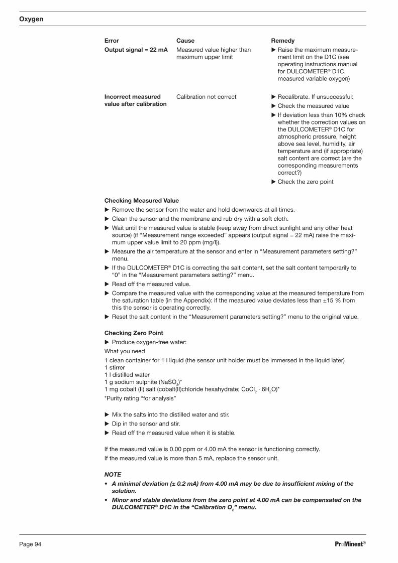
ProMinent®Page 94
Oxygen
Checking Measured Value
� Remove the sensor from the water and hold downwards at all times.
� Clean the sensor and the membrane and rub dry with a soft cloth.
� Wait until the measured value is stable (keep away from direct sunlight and any other heat source) (if “Measurement range exceeded” appears (output signal = 22 mA) raise the maxi-mum upper value limit to 20 ppm (mg/l)).
� Measure the air temperature at the sensor and enter in “Meas ure ment parameters setting?” menu.
� If the DULCOMETER® D1C is correcting the salt content, set the salt content temporarily to “0” in the “Measurement pa ram e ters setting?” menu.
� Read off the measured value.
� Compare the measured value with the corresponding value at the measured temperature from the saturation table (in the Appendix): if the measured value deviates less than ±15 % from this the sensor is operating correctly.
� Reset the salt content in the “Measurement parameters setting?” menu to the original value.
Checking Zero Point
� Produce oxygen-free water:
What you need
1 clean container for 1 l liquid (the sensor unit holder must be immersed in the liquid later) 1 stirrer 1 l distilled water 1 g sodium sulphite (NaSO3)* 1 mg cobalt (II) salt (cobalt(II)chloride hexahydrate; CoCl2 · 6H2O)*
*Purity rating “for analysis”
� Mix the salts into the distilled water and stir.
� Dip in the sensor and stir.
� Read off the measured value when it is stable.
If the measured value is 0.00 ppm or 4.00 mA the sensor is func tion ing correctly.
If the measured value is more than 5 mA, replace the sensor unit.
NOTE
• A minimal deviation (± 0.2 mA) from 4.00 mA may be due to insuffi cient mixing of the solution.
• Minor and stable deviations from the zero point at 4.00 mA can be compensated on the DULCOMETER® D1C in the “Calibration O2” menu.
Error Cause Remedy
Output signal = 22 mA
Incorrect measured value after calibration
Measured value higher than maximum upper limit
Calibration not correct
� Raise the maximum measure-ment limit on the D1C (see operating instructions manual for DULCOMETER® D1C, measured variable oxygen)
� Recalibrate. If unsuccessful:
� Check the measured value
� If deviation less than 10% check whether the correction values on the DULCOMETER® D1C for atmospheric pressure, height above sea level, humidity, air temperature and (if appropriate) salt content are correct (are the corresponding measurements correct?)
� Check the zero point
BA_DR_001_02_09_GB.indd 94BA_DR_001_02_09_GB.indd 94 24.02.2009 12:24:06 Uhr24.02.2009 12:24:06 Uhr
ProMinent® Page 95
8.7.4 DULCOMETER® D1C Measured Variable Oxygen and DULCOTEST® Sensor for Dissolved Oxygen, Maintenance
Controller
The DULCOMETER® controller type D1C for the measured variable oxygen is maintenance-free.
Sensor
Every 2-3 months Clean the sensor membrane
Every 6 months Calibrate the DO sensor
Every 2-3 years Replace the sensor unit (if used under normal operating conditions)
Cleaning the Sensor Membrane
IMPORTANT
• Do not scratch the sensor membrane.
• If the sensor is pointing upwards for longer than 3 min. during cleaning it will automati-cally replace the existing calibration data with new values. Try therefore to clean the sensor with it pointing downwards.
• Check that there is clearance all around the gold pin electrode in the hole in the side of the sensor (membrane rupture detector).
NOTE
If the sensor is pointing upward during cleaning it will emit a 4 mA signal.
� Remove the sensor from the pool.
� Rinse the sensor membrane in clean water – if necessary add a little washing up detergent.
� Dry the sensor membrane with a soft cloth.
� Place the sensor back into the pool.
Replacing Sensor Insert
IMPORTANT
• If the sensor is in use, it is essential to avoid water from reaching the contacts when replacing the sensor insert. If this cannot be avoided, dry the water off carefully using a hair dryer.
• Do not remove the silicon paste on the back of the sensor insert. It protects the contacts from short circuit even if some water has penetrated.
• The bracket of the sensor insert must be tightened and slack ened only by hand (the bracket of the sensor holder has a bayonet fi tting).
� Switch off the power.
� Remove the sensor from the pool and lay on a fi rm surface with the membrane underneath.
� Rinse the sensor with clean water
� Dry the sensor with a soft cloth until every drop has been removed.
� Remove the old sensor insert
� Place a new sensor insert (insert the two lugs on the bottom of the sensor into the cor re-spond ing holes on the transmitter).
� Switch on the power once more then run in and calibrate the sensor.
Oxygen
BA_DR_001_02_09_GB.indd 95BA_DR_001_02_09_GB.indd 95 24.02.2009 12:24:06 Uhr24.02.2009 12:24:06 Uhr
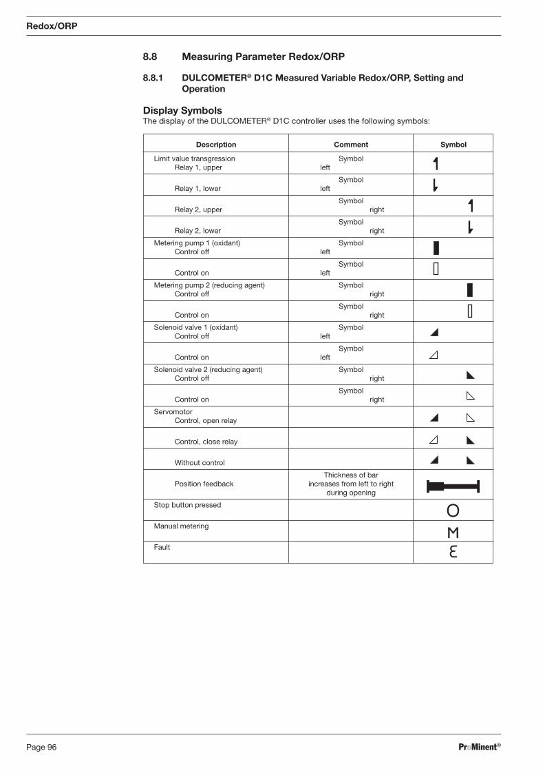
ProMinent®Page 96
Description Comment Symbol
Limit value transgression Symbol Relay 1, upper left
Symbol Relay 1, lower left
Symbol Relay 2, upper right
Symbol Relay 2, lower right
Metering pump 1 (oxidant) Symbol Control off left
Symbol Control on left
Metering pump 2 (reducing agent) Symbol Control off right
Symbol Control on right
Solenoid valve 1 (oxidant) Symbol Control off left
Symbol Control on left
Solenoid valve 2 (reducing agent) Symbol Control off right
Symbol Control on right
Servomotor Control, open relay
Control, close relay
Without control
Thickness of bar Position feedback increases from left to right during opening
Stop button pressed
Manual metering
Fault
Redox/ORP
8.8 Measuring Parameter Redox/ORP
8.8.1 DULCOMETER® D1C Measured Variable Redox/ORP, Setting and Operation
Display Symbols The display of the DULCOMETER® D1C controller uses the following symbols:
BA_DR_001_02_09_GB.indd 96BA_DR_001_02_09_GB.indd 96 24.02.2009 12:24:06 Uhr24.02.2009 12:24:06 Uhr
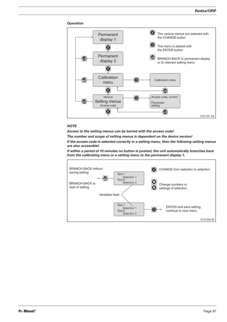
ProMinent® Page 97
Redox/ORP
Operation
NOTE
Access to the setting menus can be barred with the access code!
The number and scope of setting menus is dependent on the device version!
If the access code is selected correctly in a setting menu, then the following setting menus are also accessible!
If within a period of 10 minutes no button is pushed, the unit automatically branches back from the calibrating menu or a setting menu to the permanent display 1.
Access code, correct
Parametersetting
Calibration notes
Permanentdisplay 1
Permanentdisplay 2
Calibrationmenu
Various
Access codeSetting menus
D1C2-007-GB
The various menus are selected withthe CHANGE button
The menu is started withthe ENTER button
BRANCH BACK to permanent displayor to relevant setting menu
D1C2-008-GB
CHANGE from selection to selection
Change numbers orsettings of selection
Variables flash
ENTER and save setting,continue to next menu
BRANCH BACK withoutsaving setting
BRANCH BACK tostart of setting
Text 1
Text 2Selection 1
Selection 2
Text 1
Text 2Selection 1
Selection 2
BA_DR_001_02_09_GB.indd 97BA_DR_001_02_09_GB.indd 97 24.02.2009 12:24:06 Uhr24.02.2009 12:24:06 Uhr
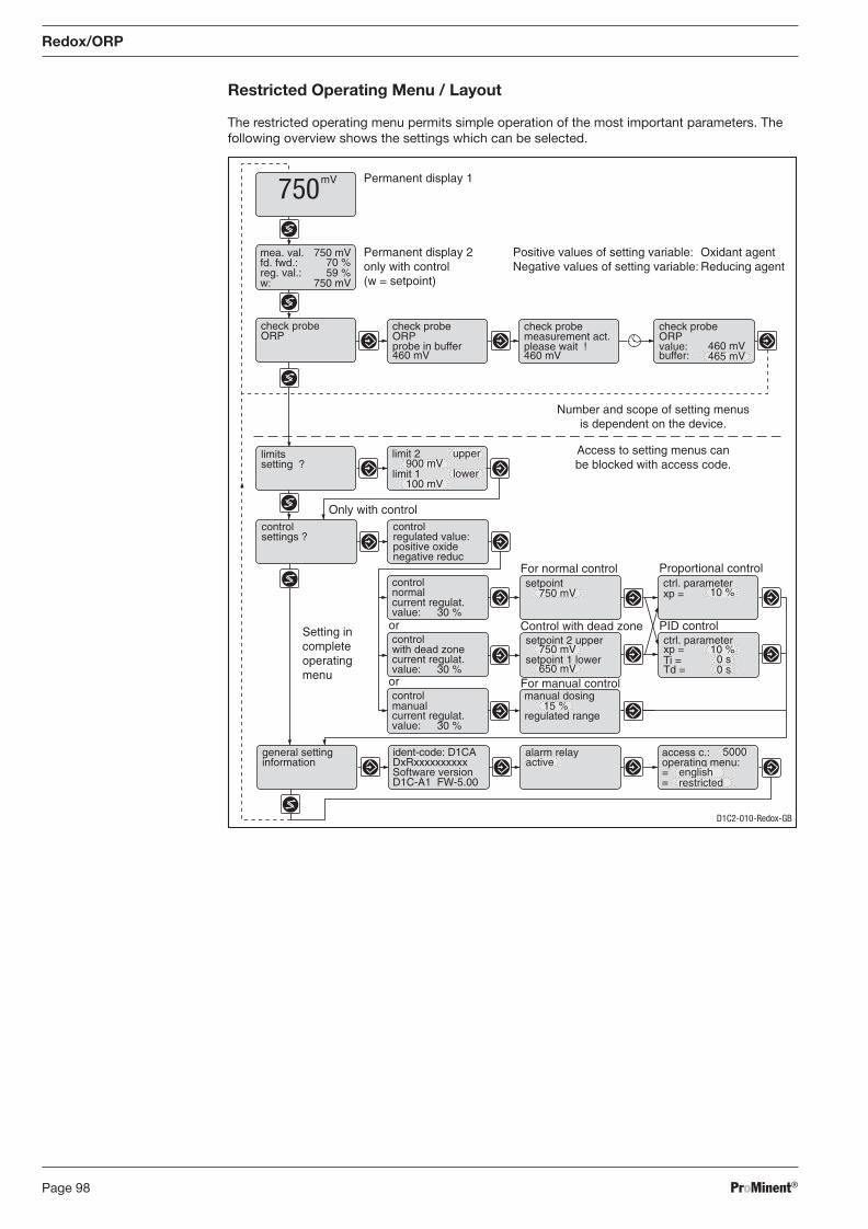
ProMinent®Page 98
Restricted Operating Menu / Layout
The restricted operating menu permits simple operation of the most important parameters. The following overview shows the settings which can be selected.
Redox/ORP
limit 2 upper900 mV
D1C2-010-Redox-GB
Permanent display 1
Permanent display 2only with control(w = setpoint)
mV750
check probeORP
check probeORPprobe in buffer460 mV
check probemeasurement act.please wait !460 mV
check probeORPvalue:buffer:
460 mV465 mV
limit 1100 mV
lower
limitssetting ?
Control with dead zone
For normal control
PID control
Proportional controlsetpoint
750 mV
setpoint 2 upper ctrl. parameter
Ti =Td =
xp =
0 s
750 mVsetpoint 1 lower
650 mV
10 %
ctrl. parameterxp = 10 %
controlsettings ?
Only with controlcontrol
positive oxideregulated value:
negative reduc
manual dosing
control
current regulat.value: 30 %
control
current regulat.value: 30 %
control
current regulat.value: 30 %
15 %regulated range
general settinginformation
ident-code: D1CA
Software versionDxRxxxxxxxxxx
D1C-A1 FW-5.00
alarm relay access c.:
==
operating menu:active5000
englishrestricted
mea. val.fd. fwd.:reg. val.:
750 mV
w: 750 mV
70 %59 %
Positive values of setting variable:Negative values of setting variable:
Oxidant agentReducing agent
manual
with dead zone
normal
or
or
Setting incompleteoperatingmenu
Number and scope of setting menusis dependent on the device.
Access to setting menus canbe blocked with access code.
0 s
For manual control
BA_DR_001_02_09_GB.indd 98BA_DR_001_02_09_GB.indd 98 24.02.2009 12:24:06 Uhr24.02.2009 12:24:06 Uhr
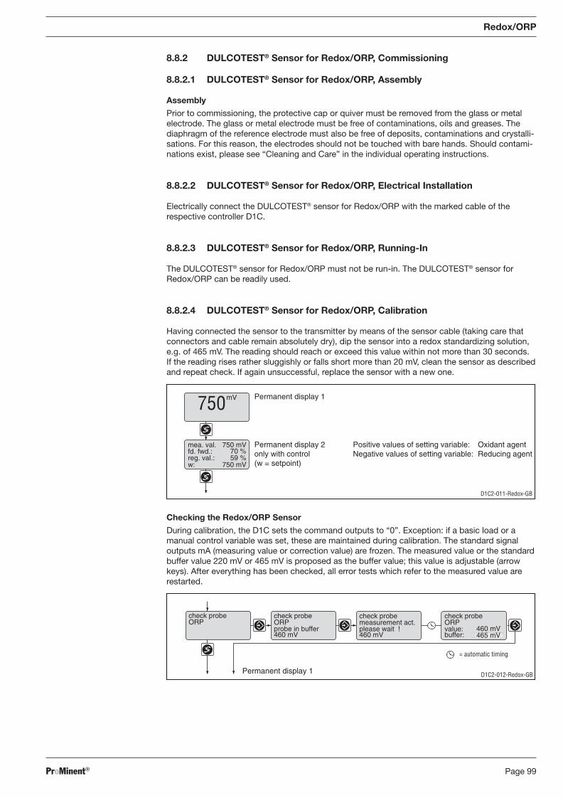
ProMinent® Page 99
Redox/ORP
8.8.2 DULCOTEST® Sensor for Redox/ORP, Commissioning
8.8.2.1 DULCOTEST® Sensor for Redox/ORP, Assembly
Assembly
Prior to commissioning, the protective cap or quiver must be removed from the glass or metal electrode. The glass or metal electrode must be free of contaminations, oils and greases. The diaphragm of the reference electrode must also be free of deposits, contaminations and crys tal li-sa tions. For this reason, the electrodes should not be touched with bare hands. Should con tam i-na tions exist, please see “Cleaning and Care” in the individual operating instructions.
8.8.2.2 DULCOTEST® Sensor for Redox/ORP, Electrical Installation
Electrically connect the DULCOTEST® sensor for Redox/ORP with the marked cable of the respective controller D1C.
8.8.2.3 DULCOTEST® Sensor for Redox/ORP, Running-In
The DULCOTEST® sensor for Redox/ORP must not be run-in. The DULCOTEST® sensor for Redox/ORP can be readily used.
8.8.2.4 DULCOTEST® Sensor for Redox/ORP, Calibration
Having connected the sensor to the transmitter by means of the sensor cable (taking care that connectors and cable remain absolutely dry), dip the sensor into a redox standardizing solution, e.g. of 465 mV. The reading should reach or exceed this value within not more than 30 seconds. If the reading rises rather sluggishly or falls short more than 20 mV, clean the sensor as described and repeat check. If again unsuccessful, replace the sensor with a new one.
D1C2-011-Redox-GB
Permanent display 1
Permanent display 2only with control(w = setpoint)
mea. val.fd. fwd.:reg. val.:
750 mV
w: 750 mV
70 %59 %
Positive values of setting variable:Negative values of setting variable:
Oxidant agentReducing agent
mV750
Checking the Redox/ORP Sensor
During calibration, the D1C sets the command outputs to “0”. Exception: if a basic load or a manual control variable was set, these are maintained during calibration. The standard signal outputs mA (measuring value or correction value) are frozen. The measured value or the standard buffer value 220 mV or 465 mV is proposed as the buffer value; this value is adjustable (arrow keys). After everything has been checked, all error tests which refer to the measured value are restarted.
D1C2-012-Redox-GB
= automatic timing
check probeORP
check probeORPprobe in buffer460 mV
check probemeasurement act.please wait !460 mV
check probeORPvalue:buffer:
460 mV465 mV
Permanent display 1
BA_DR_001_02_09_GB.indd 99BA_DR_001_02_09_GB.indd 99 24.02.2009 12:24:06 Uhr24.02.2009 12:24:06 Uhr
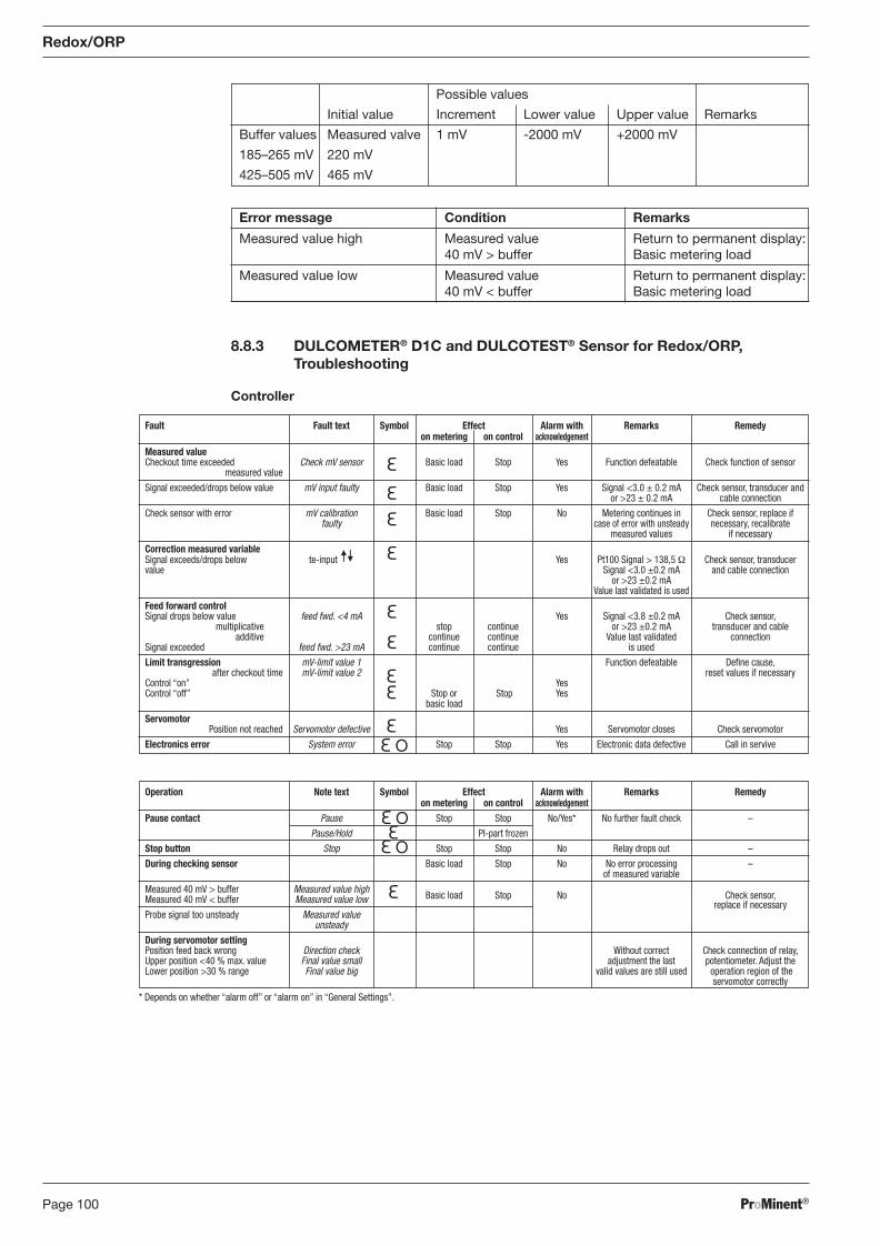
ProMinent®Page 100
Operation Note text Symbol Effect Alarm with Remarks Remedy on metering on control acknowledgement Pause contact Pause Stop Stop No/Yes* No further fault check –
Pause/Hold PI-part frozen
Stop button Stop Stop Stop No Relay drops out –
During checking sensor Basic load Stop No No error processing – of measured variable
Measured 40 mV > buffer Measured value high Measured 40 mV < buffer Measured value low Basic load Stop No Check sensor,
Probe signal too unsteady Measured value replace if necessary
unsteady
During servomotor setting Position feed back wrong Direction check Without correct Check connection of relay, Upper position <40 % max. value Final value small adjustment the last potentiometer. Adjust the Lower position >30 % range Final value big valid values are still used operation region of the servomotor correctly
Fault Fault text Symbol Effect Alarm with Remarks Remedy on metering on control acknowledgement Measured value Checkout time exceeded Check mV sensor Basic load Stop Yes Function defeatable Check function of sensor measured value
Signal exceeded/drops below value mV input faulty Basic load Stop Yes Signal <3.0 ± 0.2 mA Check sensor, transducer and or >23 ± 0.2 mA cable connection
Check sensor with error mV calibration Basic load Stop No Metering continues in Check sensor, replace if faulty case of error with unsteady necessary, recalibrate measured values if necessary
Correction measured variable Signal exceeds/drops below te-input Yes Pt100 Signal > 138,5 Ω Check sensor, transducer value Signal <3.0 ±0.2 mA and cable connection or >23 ±0.2 mA Value last validated is used
Feed forward control Signal drops below value feed fwd. <4 mA Yes Signal <3.8 ±0.2 mA Check sensor, multiplicative stop continue or >23 ±0.2 mA transducer and cable additive continue continue Value last validated connection Signal exceeded feed fwd. >23 mA continue continue is used
Limit transgression mV-limit value 1 Function defeatable Defi ne cause, after checkout time mV-limit value 2 reset values if necessary Control “on” Yes Control “off” Stop or Stop Yes basic load
Servomotor Position not reached Servomotor defective Yes Servomotor closes Check servomotor
Electronics error System error Stop Stop Yes Electronic data defective Call in servive
8.8.3 DULCOMETER® D1C and DULCOTEST® Sensor for Redox/ORP, Troubleshooting
Controller
Redox/ORP
Possible values
Initial value Increment Lower value Upper value Remarks
Buffer values Measured valve 1 mV -2000 mV +2000 mV
185–265 mV 220 mV
425–505 mV 465 mV
Error message Condition Remarks
Measured value high Measured value Return to permanent display: 40 mV > buffer Basic metering load
Measured value low Measured value Return to permanent display: 40 mV < buffer Basic metering load
* Depends on whether “alarm off” or “alarm on” in “General Settings”.
BA_DR_001_02_09_GB.indd 100BA_DR_001_02_09_GB.indd 100 24.02.2009 12:24:06 Uhr24.02.2009 12:24:06 Uhr
ProMinent® Page 101
Redox/ORP
8.8.4 DULCOMETER® D1C Measured Variable Redox/ORP and DULCOTEST® Sensor for Redox/ORP, Maintenance
Controller
The DULCOMETER® controller type D1C for the measured variable redox/ORP is mainte-nance-free.
Sensor
IMPORTANT
• The sensor is to be regularly serviced to avoid any excess metering caused by a sensor failure!
• Observe the valid national regulations for maintenance intervals!
• Do not touch the electrodes or bring into contact with greasy substances!
Maintenance interval monthly
Maintenance Work
The sensor should regularly (once a month) undergo a visual check and be cleaned if necessary.
If deposits on the glass electrode withstand cleaning with a soft, moistened cloth, the following cleaning agents may be used:
Kind of deposit Agent and duration of application
General deposits Non-abrasive household cleaner
Scale or metal hydroxides Diluted hydrochloric acid (approx. 0.1-3 %, 1-5 minutes)
Oil, grease Solvents, like alcohol or acetone
Biofouling Mixture of diluted hydrochloric acid and pepsin, several hours Solvents (e.g. acetone) must not be used to clean electrodes as they can demage the plastic stems.
It is essential that the sensors are rinsed thoroughly after having been cleaned. In addition, the metal surfaces of redox sensors may be cleaned by sanding and polishing. If the laterally arranged ceramic diaphragm of the reference electrode is blocked, it may be cleaned like the glass electrode. In addition it may be cleaned by cautious scraping with a fi nger nail, a razor blade or a fi ne fi le, but care must be taken that the diaphragm is not scratched.
BA_DR_001_02_09_GB.indd 101BA_DR_001_02_09_GB.indd 101 24.02.2009 12:24:06 Uhr24.02.2009 12:24:06 Uhr
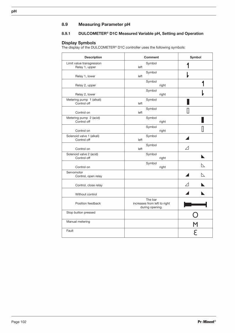
ProMinent®Page 102
8.9 Measuring Parameter pH
8.9.1 DULCOMETER® D1C Measured Variable pH, Setting and Operation
Display Symbols The display of the DULCOMETER® D1C controller uses the following symbols:
Description Comment Symbol
Limit value transgression Symbol Relay 1, upper left
Symbol Relay 1, lower left
Symbol Relay 2, upper right
Symbol Relay 2, lower right
Metering pump 1 (alkali) Symbol Control off left
Symbol Control on left
Metering pump 2 (acid) Symbol Control off right
Symbol Control on right
Solenoid valve 1 (alkali) Symbol Control off left
Symbol Control on left
Solenoid valve 2 (acid) Symbol Control off right
Symbol Control on right
Servomotor Control, open relay
Control, close relay
Without control
The bar Position feedback increases from left to right during opening.
Stop button pressed
Manual metering
Fault
pH
BA_DR_001_02_09_GB.indd 102BA_DR_001_02_09_GB.indd 102 24.02.2009 12:24:06 Uhr24.02.2009 12:24:06 Uhr
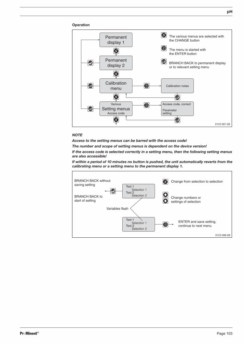
ProMinent® Page 103
pH
Operation
NOTE
Access to the setting menus can be barred with the access code!
The number and scope of setting menus is dependent on the device version!
If the access code is selected correctly in a setting menu, then the following setting menus are also accessible!
If within a period of 10 minutes no button is pushed, the unit automatically reverts from the calibrating menu or a setting menu to the permanent display 1.
Access code, correct
Parametersetting
Calibration notes
Permanentdisplay 1
Permanentdisplay 2
Calibrationmenu
Various
Access codeSetting menus
D1C2-007-GB
The various menus are selected withthe CHANGE button
The menu is started withthe ENTER button
BRANCH BACK to permanent displayor to relevant setting menu
D1C2-008-GB
Change from selection to selection
Change numbers orsettings of selection
Variables flash
ENTER and save setting,continue to next menu
BRANCH BACK withoutsaving setting
BRANCH BACK tostart of setting
Text 1
Text 2Selection 1
Selection 2
Text 1
Text 2Selection 1
Selection 2
BA_DR_001_02_09_GB.indd 103BA_DR_001_02_09_GB.indd 103 24.02.2009 12:24:06 Uhr24.02.2009 12:24:06 Uhr
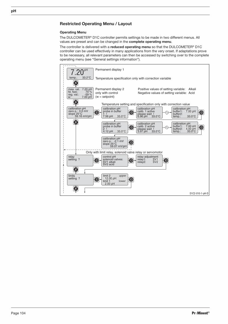
ProMinent®Page 104
Restricted Operating Menu / Layout
Operating Menu
The DULCOMETER® D1C controller permits settings to be made in two different menus. All values are preset and can be changed in the complete operating menu.
The controller is delivered with a reduced operating menu so that the DULCOMETER® D1C controller can be used effectively in many applications from the very onset. If adaptations prove to be necessary, all relevant parameters can then be accessed by switching over to the complete operating menu (see “General settings information”).
pH
Permanent display 1
Permanent display 2only with control(w = setpoint)
Temperature specification only with correction variabletemp.: 33.2°C
pH7.20
Temperature setting and specification only with correction valuecalibration pHzero p.:slope 25°C
0.0 mV
59.16 mV/pH
calibration pHzero p.:slope 25°C
-2.1 mV
59.07 mV/pH
calibration pHprobe in buffer1 !7.56 pH 33.0°C
calibration pHcalib. 1 activeplease wait !6.96 pH 33.0°C
calibration pHbuffer1:buffer2:temp.: 33.0°C
calibration pHcalib. 2 activeplease wait !3.97 pH 33.0°C
7.00 pH
calibration pHbuffer1:buffer2:temp.: 33.0°C
7.00 pH4.00 pH
calibration pHprobe in buffer2 !4.12 pH 33.0°C
Only with limit relay, solenoid valve relay or servomotorrelaysetting ?
relay adjustmentrelay1:relay2:
control pHsolenoid valves:SV1 alkaliSV2 acid
SV1SV2
limitssetting ?
mea. val.fd. fwd.:reg. val.:
7.20 pH70 %
-59 %
Positive values of setting variable:Negative values of setting variable:
AlkaliAcid
w: 7.00 pH
limit 1 lower
limit 212.00 pH
upper
2.00 pH
D1C2-010-1-pH-D
BA_DR_001_02_09_GB.indd 104BA_DR_001_02_09_GB.indd 104 24.02.2009 12:24:06 Uhr24.02.2009 12:24:06 Uhr
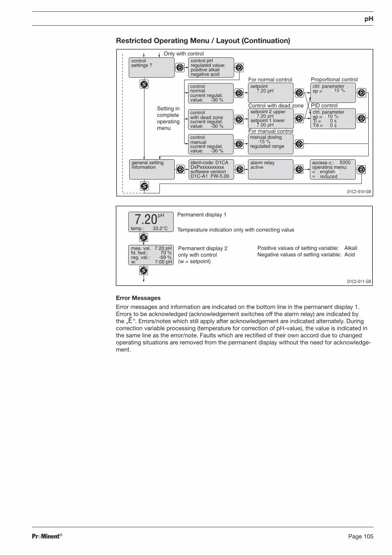
ProMinent® Page 105
pH
Restricted Operating Menu / Layout (Continuation)
Error Messages
Error messages and information are indicated on the bottom line in the permanent display 1. Errors to be acknowledged (acknowledgement switches off the alarm relay) are indicated by the „ “. Errors/notes which still apply after acknowledgement are indicated alternately. During correction variable processing (temperature for correction of pH-value), the value is indicated in the same line as the error/note. Faults which are rectifi ed of their own accord due to changed operating situations are removed from the permanent display without the need for acknowledge-ment.
control
current regulat.value: -30 %
with dead zone
control
current regulat.value: -30 %
manual
D1C2-010-GB
Control with dead zone
For normal control
PID control
Proportional controlsetpoint
7.20 pH
ctrl. parameter
Ti =Td =
xp =
ctrl. parameterxp = 10 %
controlsettings ?
control pH
positive alkaliregulated value:
negative acid
manual dosing
control
current regulat.value: -30 %
normal
-15 %regulated range
general settinginformation
ident-code: D1CA
software versionDxPxxxxxxxxxx
D1C-A1 FW-5.00
alarm relay access c.:
==
operating menu:active5000
english
For manual control
setpoint 2 upper
setpoint 1 lower7.20 pH
7.00 pH
Setting incompleteoperatingmenu
Only with control
reduced
0 s
10 %0 s
D1C2-011-GB
Permanent display 1
Temperature indication only with correcting valuetemp.: 33.2°C
pH7.20
mea. val.fd. fwd.:reg. val.:
7.20 pH70 %
-59 %
Positive values of setting variable:Negative values of setting variable:
AlkaliAcid
Permanent display 2only with control(w = setpoint)w: 7.00 pH
BA_DR_001_02_09_GB.indd 105BA_DR_001_02_09_GB.indd 105 24.02.2009 12:24:06 Uhr24.02.2009 12:24:06 Uhr
ProMinent®Page 106
8.9.2 DULCOTEST® PHEP or PHER Sensor for pH, Commissioning
8.9.2.1 DULCOTEST® PHEP or PHER Sensor for pH, Assembly
Remove the blanking plug of the respective measuring module at the fi ttings of the measuring/control station DULCOTROL® drinking water/F&B and install the DULCOTEST® PHEP or PHER sensor for pH.
8.9.2.2 DULCOTEST® PHEP or PHER Sensor for pH, Electrical Installation
Connect the DULCOTEST® PHEP or PHER sensor for pH with the marked cable of the respective controller D1C.
8.9.2.3 DULCOTEST® PHEP or PHER Sensor for pH, Running-In
The DULCOTEST® PHEP or PHER sensor for pH must not be run-in. The DULCOTEST® PHEP or PHER sensor for pH can be readily used.
8.9.2.4 DULCOTEST® PHEP or PHER Sensor for pH, Calibration
Since pH sensors are subject to certain manufacturing tolerances, they must be tuned to the pertinent pH transmitter. The adjustment intervals depend on relevant operating conditions. They can vary from a few days to up to 8 weeks.
Having connected the sensor to the transmitter by means of the sensor cable (taking care that connectors and cable remain absolutely dry), dip the sensor into a pH 7 standardizing solution and adjust transmitter exactly to read this value.
Remove the sensor, rinse it with water, preferably distilled water, and dry it by swabbing it with soft, non-fl uffi ng tissue paper.
IMPORTANT
Do not rub since this might cause static electricity and false readings.
Immerse the sensor in a buffer solution differing by a least 2 pH from pH 7 and calibrate after the value on the display has stabilised. If within 30 seconds a steady-state value is not produced or calibration has proved impossible, clean sensor and repeat calibration. If again unsuccessful, replace sensor with a new one.
pH
BA_DR_001_02_09_GB.indd 106BA_DR_001_02_09_GB.indd 106 24.02.2009 12:24:06 Uhr24.02.2009 12:24:06 Uhr
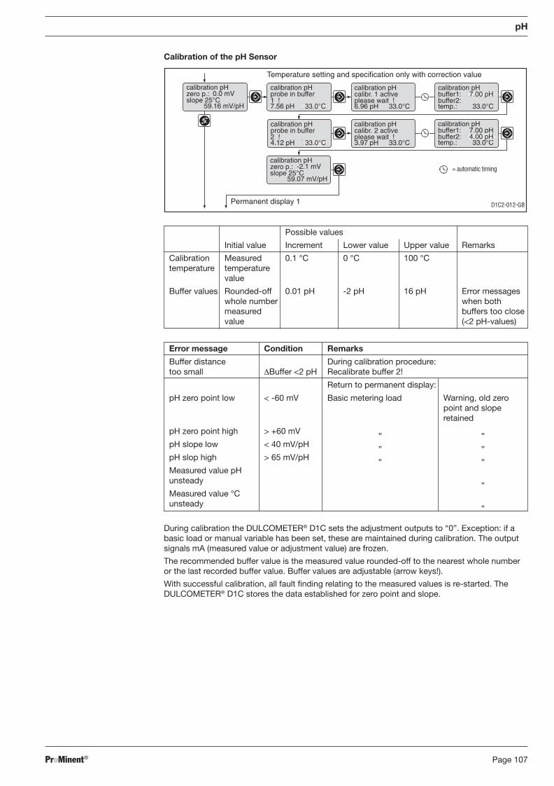
ProMinent® Page 107
Possible values
Initial value Increment Lower value Upper value Remarks
Calibration Measured 0.1 °C 0 °C 100 °C temperature temperature value
Buffer values Rounded-off 0.01 pH -2 pH 16 pH Error messages whole number when both measured buffers too close value (<2 pH-values)
D1C2-012-GB
Temperature setting and specification only with correction value
calibration pHzero p.:slope 25°C
0.0 mV
59.16 mV/pH
calibration pHzero p.:slope 25°C
-2.1 mV
59.07 mV/pH
calibration pHprobe in buffer1 !7.56 pH 33.0°C
calibration pHcalibr. 1 activeplease wait !6.96 pH 33.0°C
calibration pHbuffer1:buffer2:temp.: 33.0°C
calibration pHcalibr. 2 activeplease wait !3.97 pH 33.0°C
7.00 pH
calibration pHbuffer1:buffer2:temp.: 33.0°C
7.00 pH4.00 pH
calibration pHprobe in buffer2 !4.12 pH 33.0°C
= automatic timing
Permanent display 1
pH
Calibration of the pH Sensor
During calibration the DULCOMETER® D1C sets the adjustment outputs to “0”. Exception: if a basic load or manual variable has been set, these are maintained during calibration. The output signals mA (measured value or adjustment value) are frozen.
The recommended buffer value is the measured value rounded-off to the nearest whole number or the last recorded buffer value. Buffer values are adjustable (arrow keys!).
With successful calibration, all fault fi nding relating to the measured values is re-started. The DULCOMETER® D1C stores the data established for zero point and slope.
Error message Condition Remarks
Buffer distance During calibration procedure: too small ΔBuffer <2 pH Recalibrate buffer 2!
Return to permanent display:
pH zero point low < -60 mV Basic metering load Warning, old zero point and slope retained
pH zero point high > +60 mV „ „
pH slope low < 40 mV/pH „ „
pH slop high > 65 mV/pH „ „
Measured value pH unsteady „
Measured value °C unsteady „
BA_DR_001_02_09_GB.indd 107BA_DR_001_02_09_GB.indd 107 24.02.2009 12:24:07 Uhr24.02.2009 12:24:07 Uhr
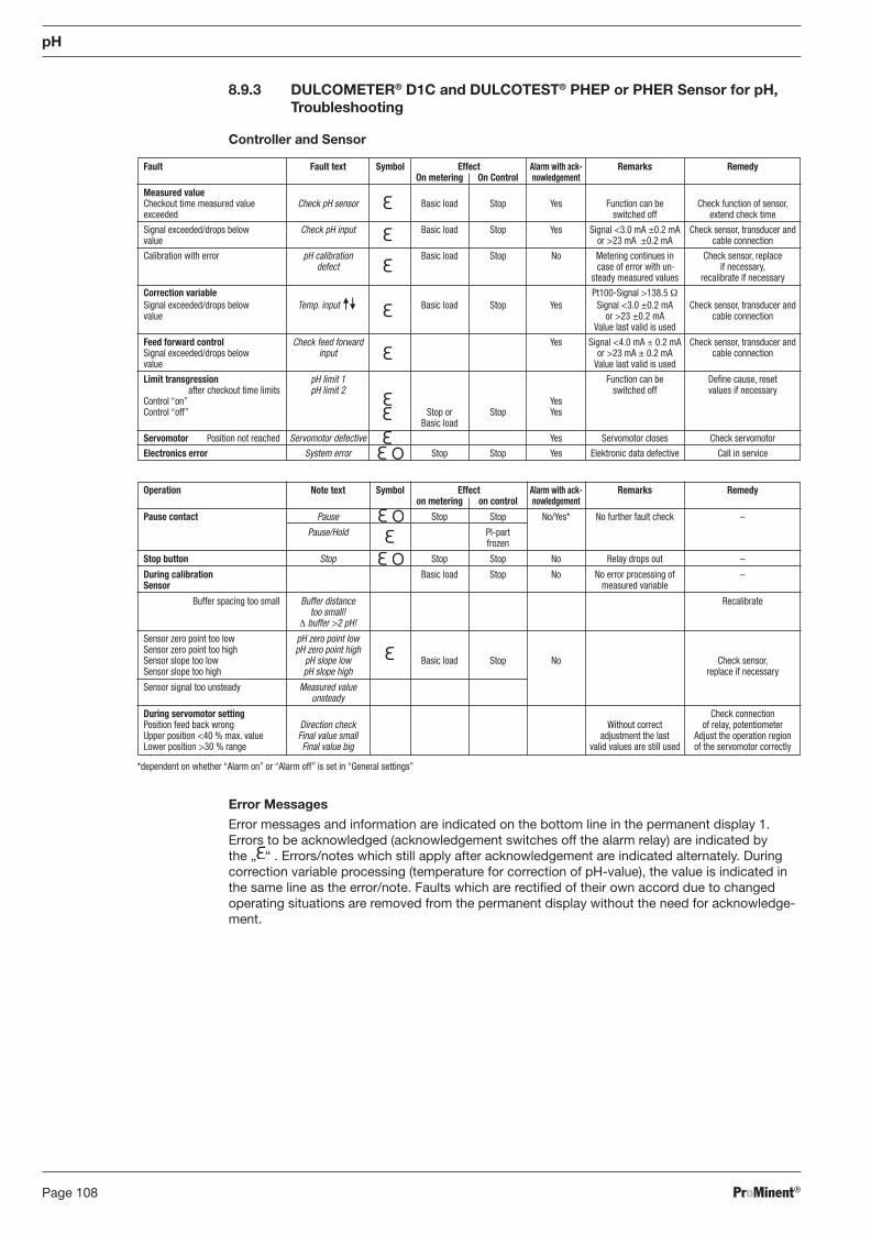
ProMinent®Page 108
Operation Note text Symbol Effect Alarm with ack- Remarks Remedy on metering on control nowledgement
Pause contact Pause Stop Stop No/Yes* No further fault check –
Pause/Hold Pl-part frozen
Stop button Stop Stop Stop No Relay drops out –
During calibration Basic load Stop No No error processing of – Sensor measured variable
Buffer spacing too small Buffer distance Recalibrate too small! Δ buffer >2 pH!
Sensor zero point too low pH zero point low Sensor zero point too high pH zero point high Sensor slope too low pH slope low Basic load Stop No Check sensor, Sensor slope too high pH slope high replace if necessary
Sensor signal too unsteady Measured value unsteady
During servomotor setting Check connection Position feed back wrong Direction check Without correct of relay, potentiometer Upper position <40 % max. value Final value small adjustment the last Adjust the operation region Lower position >30 % range Final value big valid values are still used of the servomotor correctly
*dependent on whether “Alarm on” or “Alarm off” is set in “General settings”
Fault Fault text Symbol Effect Alarm with ack- Remarks Remedy On metering On Control nowledgement Measured value Checkout time measured value Check pH sensor Basic load Stop Yes Function can be Check function of sensor, exceeded switched off extend check time
Signal exceeded/drops below Check pH input Basic load Stop Yes Signal <3.0 mA ±0.2 mA Check sensor, transducer and value or >23 mA ±0.2 mA cable connection
Calibration with error pH calibration Basic load Stop No Metering continues in Check sensor, replace defect case of error with un- if necessary, steady measured values recalibrate if necessary
Correction variable Pt100-Signal >138.5 Ω Signal exceeded/drops below Temp. input . Basic load Stop Yes Signal <3.0 ±0.2 mA Check sensor, transducer and value or >23 ±0.2 mA cable connection Value last valid is used
Feed forward control Check feed forward Yes Signal <4.0 mA ± 0.2 mA Check sensor, transducer and Signal exceeded/drops below input or >23 mA ± 0.2 mA cable connection value Value last valid is used
Limit transgression pH limit 1 Function can be Defi ne cause, reset after checkout time limits pH limit 2 switched off values if necessary Control “on” Yes Control “off” Stop or Stop Yes Basic load
Servomotor Position not reached Servomotor defective Yes Servomotor closes Check servomotor
Electronics error System error Stop Stop Yes Elektronic data defective Call in service
pH
8.9.3 DULCOMETER® D1C and DULCOTEST® PHEP or PHER Sensor for pH, Troubleshooting
Controller and Sensor
Error Messages
Error messages and information are indicated on the bottom line in the permanent display 1. Errors to be acknowledged (acknowledgement switches off the alarm relay) are indicated by the „ “ . Errors/notes which still apply after acknowledgement are indicated alternately. During correction variable processing (temperature for correction of pH-value), the value is indicated in the same line as the error/note. Faults which are rectifi ed of their own accord due to changed operating situations are removed from the permanent display without the need for acknowledge-ment.
BA_DR_001_02_09_GB.indd 108BA_DR_001_02_09_GB.indd 108 24.02.2009 12:24:07 Uhr24.02.2009 12:24:07 Uhr
ProMinent® Page 109
8.9.4 DULCOMETER® D1C Measured Variable pH and DULCOTEST® PHEP or PHER Sensor for pH, Maintenance
Controller
The DULCOMETER® controller type D1C for the measured variable pH is maintenance-free.
Sensor
IMPORTANT
• The sensor is to be regularly serviced to avoid any excess metering caused by a sensor failure!
• Observe the valid national regulations for maintenance intervals!
• Do not touch the electrodes or bring into contact with greasy substances!
Maintenance interval monthly
Maintenance Work
The sensor should regularly (once a month) undergo a visual check and be cleaned if necessary.
If deposits on the glass electrode withstand cleaning with a soft, moistened cloth, the following cleaning agents may be used.
Kind of deposit Agent and duration of application
General deposits Non-abrasive household cleaner
Scale or metal hydroxides Diluted hydrochloric acid (approx. 0.1-3 %, 1-5 minutes)
Oil, grease Solvents, like alcohol or acetone
Biofouling Mixture of diluted hydrochloric acid and pepsin, several hours Solvents (e.g. acetone) must not be used to clean electrodes as they can demage the plastic stems.
It is essential that the sensor are rinsed thoroughly after having been cleaned.
pH
BA_DR_001_02_09_GB.indd 109BA_DR_001_02_09_GB.indd 109 24.02.2009 12:24:07 Uhr24.02.2009 12:24:07 Uhr
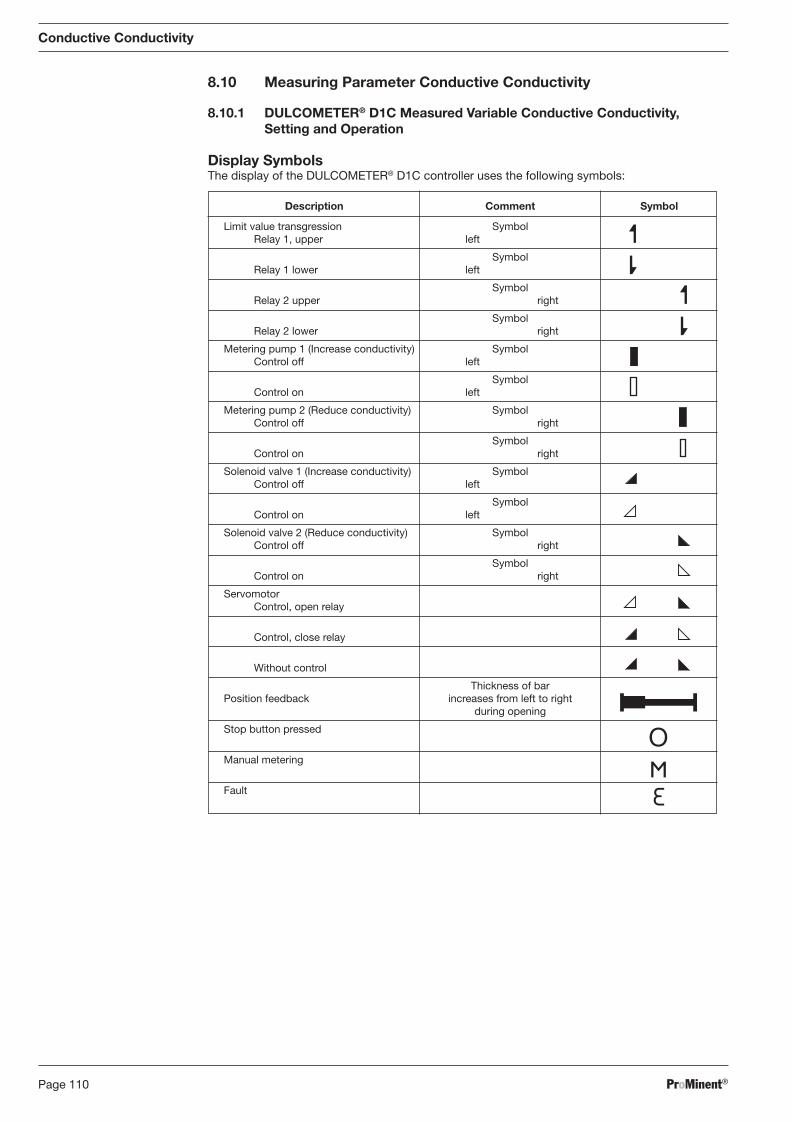
ProMinent®Page 110
8.10 Measuring Parameter Conductive Conductivity
8.10.1 DULCOMETER® D1C Measured Variable Conductive Conductivity, Setting and Operation
Display Symbols The display of the DULCOMETER® D1C controller uses the following symbols:
Description Comment Symbol
Limit value transgression Symbol Relay 1, upper left
Symbol Relay 1 lower left
Symbol Relay 2 upper right
Symbol Relay 2 lower right
Metering pump 1 (Increase conductivity) Symbol Control off left
Symbol Control on left
Metering pump 2 (Reduce conductivity) Symbol Control off right
Symbol Control on right
Solenoid valve 1 (Increase conductivity) Symbol Control off left
Symbol Control on left
Solenoid valve 2 (Reduce conductivity) Symbol Control off right
Symbol Control on right
Servomotor Control, open relay
Control, close relay
Without control
Thickness of bar Position feedback increases from left to right during opening
Stop button pressed
Manual metering
Fault
Conductive Conductivity
BA_DR_001_02_09_GB.indd 110BA_DR_001_02_09_GB.indd 110 24.02.2009 12:24:07 Uhr24.02.2009 12:24:07 Uhr
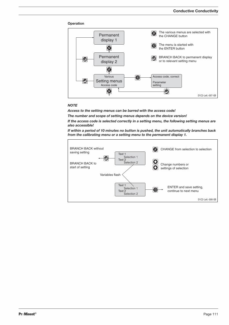
ProMinent® Page 111
Conductive Conductivity
Operation
NOTE
Access to the setting menus can be barred with the access code!
The number and scope of setting menus depends on the device version!
If the access code is selected correctly in a setting menu, the following setting menus are also accessible!
If within a period of 10 minutes no button is pushed, the unit automatically branches back from the calibrating menu or a setting menu to the permanent display 1.
D1C2-Leit.-007-GB
Access code, correct
Parametersetting
Permanentdisplay 1
Permanentdisplay 2
Various
Access codeSetting menus
The various menus are selected withthe CHANGE button
The menu is started withthe ENTER button
BRANCH BACK to permanent displayor to relevant setting menu
CHANGE from selection to selection
Change numbers orsettings of selection
Variables flash
ENTER and save setting,continue to next menu
BRANCH BACK withoutsaving setting
BRANCH BACK tostart of setting
Text 1
Text 2Selection 1
Selection 2
Text 1
Text 2Selection 1
Selection 2
D1C2-Leit.-008-GB
BA_DR_001_02_09_GB.indd 111BA_DR_001_02_09_GB.indd 111 24.02.2009 12:24:07 Uhr24.02.2009 12:24:07 Uhr
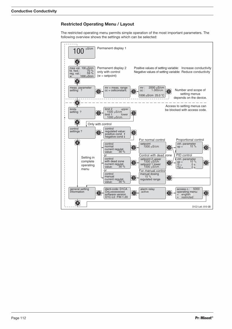
ProMinent®Page 112
Conductive Conductivity
Restricted Operating Menu / Layout
The restricted operating menu permits simple operation of the most important parameters. The following overview shows the settings which can be selected:
Permanent display 1
100 μS/cm
w: 1000 μS/cm
70 %59 %
μS/cm100
Increase conductivityReduce conductivity
mea val. Permanent display 2only with control(w = setpoint)
fd. fwd.:reg. val.:
Positive values of setting variable:Negative values of setting variable:
D1C-L0 FW-1.20
D1C2-Leit.-010-GB
1000 μS/cm
Ti =Td =
xp =
0 s
10 %
xp = 10 %
30 %
15 %
DxLxxxxxxxxxx==
5000
1500 μS/cm
1000 μS/cm
limitssetting ?
controlsettings ?
Only with controlcontrol
positive condregulated value:
negative cond
control
current regulat.value:
normal
30 %
control
current regulat.value:
with dead zone
30 %
control
current regulat.value:
manual
Control with dead zone
For normal control
PID control
Proportional controlsetpoint
setpoint 2 upper ctrl. parameter
setpoint 1 lower
ctrl. parameter
manual dosing
regulated range
general settinginformation
ident-code: D1CA
software version
alarm relay access c.:operating menu:active
english
mr = meas. rangecc = cellconstant.
2000 μS/cmcc : 1.000/cmmr :
1006 μS/cm 25.0 °C
meas. parametersetting ?
1000 μS/cmlimit 1 lower
1500 μS/cmlimit 2 upper
Access to setting menus canbe blocked with access code.
or
or
For manual control
Setting incompleteoperatingmenu
0 s
Number and scope ofsetting menus
depends on the device.
restricted
BA_DR_001_02_09_GB.indd 112BA_DR_001_02_09_GB.indd 112 24.02.2009 12:24:07 Uhr24.02.2009 12:24:07 Uhr
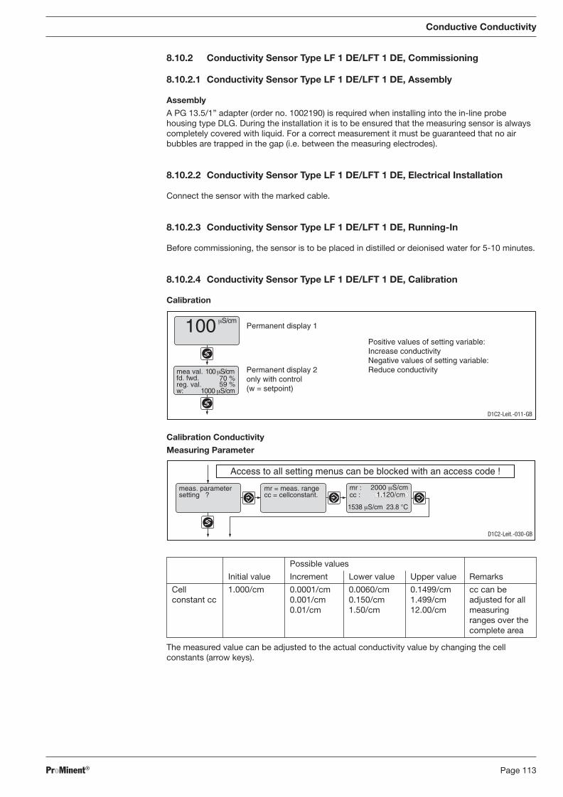
ProMinent® Page 113
Conductive Conductivity
8.10.2 Conductivity Sensor Type LF 1 DE/LFT 1 DE, Commissioning
8.10.2.1 Conductivity Sensor Type LF 1 DE/LFT 1 DE, Assembly
Assembly
A PG 13.5/1” adapter (order no. 1002190) is required when installing into the in-line probe housing type DLG. During the installation it is to be ensured that the measuring sensor is always completely covered with liquid. For a correct measurement it must be guaranteed that no air bubbles are trapped in the gap (i.e. between the measuring electrodes).
8.10.2.2 Conductivity Sensor Type LF 1 DE/LFT 1 DE, Electrical Installation
Connect the sensor with the marked cable.
8.10.2.3 Conductivity Sensor Type LF 1 DE/LFT 1 DE, Running-In
Before commissioning, the sensor is to be placed in distilled or deionised water for 5-10 minutes.
8.10.2.4 Conductivity Sensor Type LF 1 DE/LFT 1 DE, Calibration
Calibration
Positive values of setting variable:Increase conductivityNegative values of setting variable:Reduce conductivity
D1C2-Leit.-011-GB
Permanent display 1
Permanent display 2only with control(w = setpoint)
100 μS/cm
mea val.fd. fwd.reg. val. 59 %
70 %
w:
100 μS/cm
1000 μS/cm
Calibration Conductivity
Measuring Parameter
2000 μS/cm
1538 μS/cm 23.8 °C
D1C2-Leit.-030-GB
Access to all setting menus can be blocked with an access code !
mr = meas. rangecc = cellconstant. cc :
mr :meas. parametersetting ? 1.120/cm
Possible values
Initial value Increment Lower value Upper value Remarks
Cell 1.000/cm 0.0001/cm 0.0060/cm 0.1499/cm cc can be constant cc 0.001/cm 0.150/cm 1.499/cm adjusted for all 0.01/cm 1.50/cm 12.00/cm measuring
ranges over the com plete area
The measured value can be adjusted to the actual conductivity value by changing the cell constants (arrow keys).
BA_DR_001_02_09_GB.indd 113BA_DR_001_02_09_GB.indd 113 24.02.2009 12:24:07 Uhr24.02.2009 12:24:07 Uhr
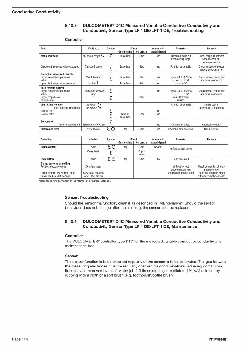
ProMinent®Page 114
Operation Note text Symbol Effect Alarm with Remarks Remedy On metering On control acknowledgement
Pause contact Pause Stop Stop No/Yes* No further fault check –
Pause/Hold PI part frozen
Stop button Stop Stop Stop No Relay drops out –
During servomotor setting Position feedback wrong Direction check Without correct Check connection of relay, adjustment the last potentiometer Upper position <40 % max. value Final value too small valid values are still used Adjust the operation region Lower position >30 % range Final value too big of the servomotor correctly
*Depends on whether “alarm off” or “alarm on” in “General Settings”.
8.10.3 DULCOMETER® D1C Measured Variable Conductive Conductivity and Conductivity Sensor Type LF 1 DE/LFT 1 DE, Troubleshooting
Controller
Fault Fault text Symbol Effect Alarm with Remarks Remedy On metering On control acknowledgement
Measured value mS-meas. range Basic load Stop Yes Measured value out Check range adjustment of measuring range. Check sensor and cable connection
Checkout time meas. value exceeded Check mS-sensor Basic load Stop Yes Function detachable Check function of sensor, Extend checkout time
Correction measured variable Signal exceeds/drops below Check te-input Basic load Stop Yes Signal <3.0 ±0.2 mA Check sensor, transducer value or >23 ±0.2 mA and cable connection upper limit temperature exceeded te-limit Basic load Stop Yes α ≥ 4 %/°C
Feed forward control Signal exceeds/drops below Check feed forward Yes Signal <3.0 ±0.2 mA Check sensor, transducer value input or >23 ±0.2 mA and cable connection Signal drops below " Stop Value last valid multiplicative is used
Limit value violation mS-limit 1 Function detachable Defi ne cause, after checkout time limits mS-limit 2 reset values if necessary Control “on” Yes Control “off” Stop or Stop Yes basic load
Servomotor Position not reached Servomotor defective Yes Servomotor closes Check servomotor
Electronics error System error Stop Stop Yes Electronic data defective Call in service
Conductive Conductivity
Sensor: Troubleshooting
Should the sensor malfunction, clean it as described in “Maintenance”. Should the sensor behaviour does not change after the cleaning, the sensor is to be replaced.
8.10.4 DULCOMETER® D1C Measured Variable Conductive Conductivity and Conductivity Sensor Type LF 1 DE/LFT 1 DE, Maintenance
Controller
The DULCOMETER® controller type D1C for the measured variable conductive conductivity is maintenance-free.
Sensor
The sensor function is to be checked regularly or the sensor is to be calibrated. The gap between the measuring electrodes must be regularly checked for contaminations. Adhering contamina-tions may be removed by a soft water jet, 2-3 times dipping into diluted (1% w/v) acids or by rubbing with a cloth or a soft brush (e.g. toothbrush/bottle brush).
BA_DR_001_02_09_GB.indd 114BA_DR_001_02_09_GB.indd 114 24.02.2009 12:24:07 Uhr24.02.2009 12:24:07 Uhr
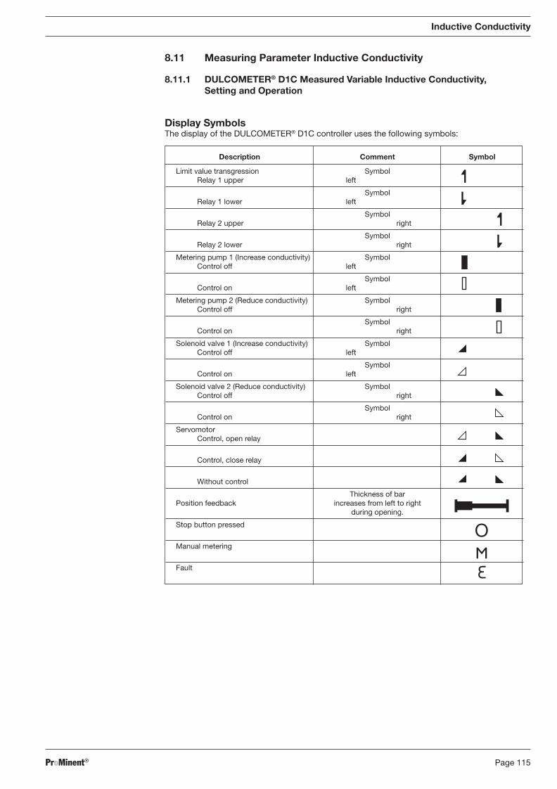
ProMinent® Page 115
Inductive Conductivity
8.11 Measuring Parameter Inductive Conductivity
8.11.1 DULCOMETER® D1C Measured Variable Inductive Conductivity, Setting and Operation
Display Symbols The display of the DULCOMETER® D1C controller uses the following symbols:
Description Comment Symbol
Limit value transgression Symbol Relay 1 upper left
Symbol Relay 1 lower left
Symbol Relay 2 upper right
Symbol Relay 2 lower right
Metering pump 1 (Increase conductivity) Symbol Control off left
Symbol Control on left
Metering pump 2 (Reduce conductivity) Symbol Control off right
Symbol Control on right
Solenoid valve 1 (Increase conductivity) Symbol Control off left
Symbol Control on left
Solenoid valve 2 (Reduce conductivity) Symbol Control off right
Symbol Control on right
Servomotor Control, open relay
Control, close relay
Without control
Thickness of bar Position feedback increases from left to right during opening.
Stop button pressed
Manual metering
Fault
BA_DR_001_02_09_GB.indd 115BA_DR_001_02_09_GB.indd 115 24.02.2009 12:24:07 Uhr24.02.2009 12:24:07 Uhr
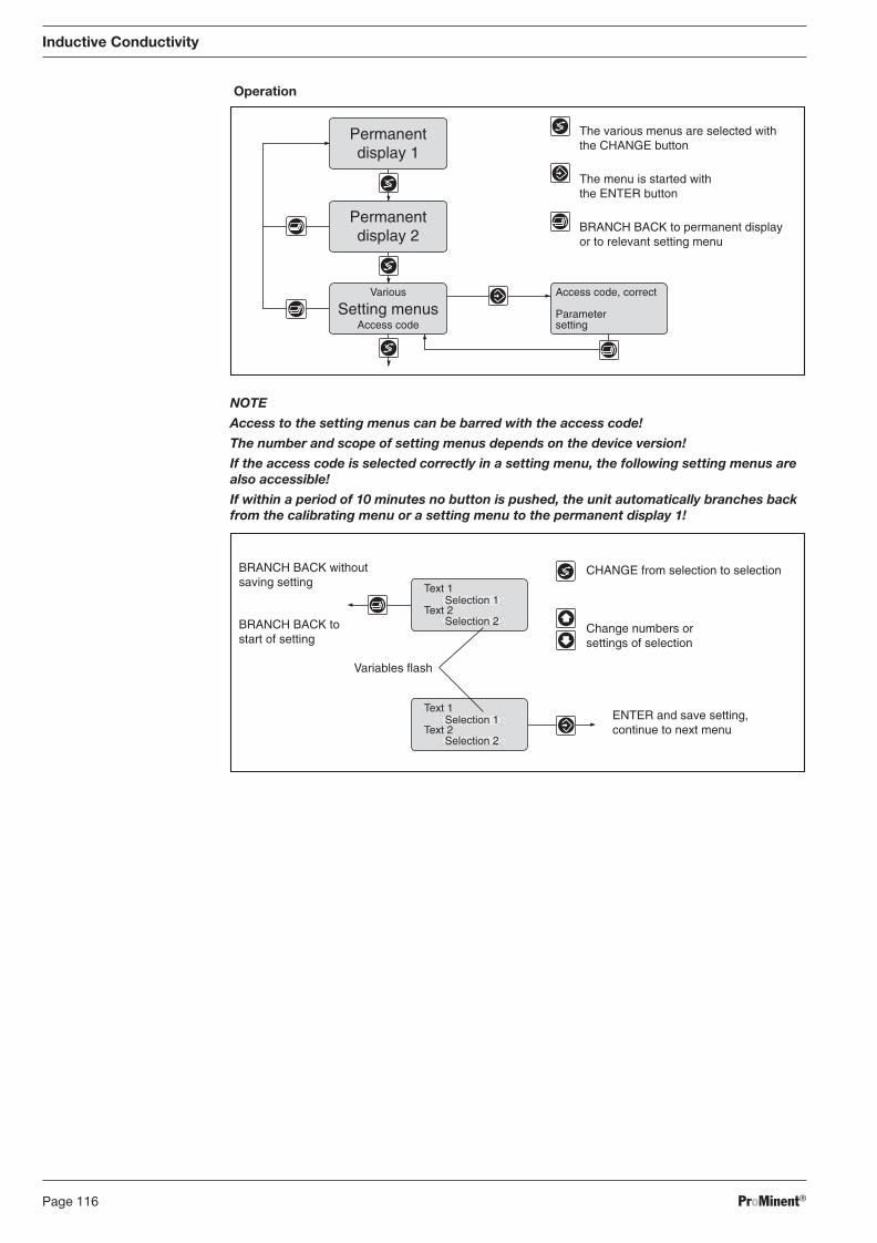
ProMinent®Page 116
Operation
Inductive Conductivity
NOTE
Access to the setting menus can be barred with the access code!
The number and scope of setting menus depends on the device version!
If the access code is selected correctly in a setting menu, the following setting menus are also accessible!
If within a period of 10 minutes no button is pushed, the unit automatically branches back from the calibrating menu or a setting menu to the permanent display 1!
Access code, correct
Parametersetting
Permanentdisplay 1
Permanentdisplay 2
Various
Access codeSetting menus
The various menus are selected withthe CHANGE button
The menu is started withthe ENTER button
BRANCH BACK to permanent displayor to relevant setting menu
CHANGE from selection to selection
Change numbers orsettings of selection
Variables flash
ENTER and save setting,continue to next menu
BRANCH BACK withoutsaving setting
BRANCH BACK tostart of setting
Text 1
Text 2Selection 1
Selection 2
Text 1
Text 2Selection 1
Selection 2
BA_DR_001_02_09_GB.indd 116BA_DR_001_02_09_GB.indd 116 24.02.2009 12:24:08 Uhr24.02.2009 12:24:08 Uhr
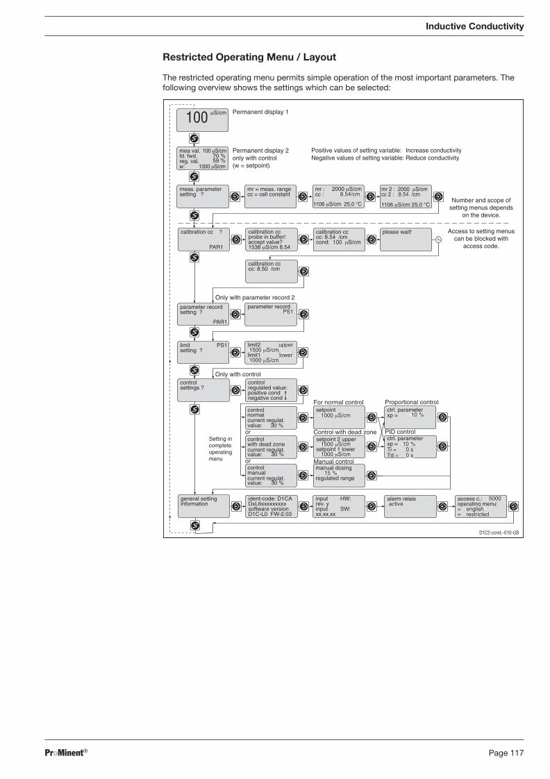
ProMinent® Page 117
Inductive Conductivity
Restricted Operating Menu / Layout
The restricted operating menu permits simple operation of the most important parameters. The following overview shows the settings which can be selected:
mr 2 : 2000 μS/cmcc 2 : 8.54 /cm
1106 μS/cm 25,0 °C
D1C2-cond.-010-GB
Access to setting menuscan be blocked with
access code.
access c.:
==
operating menu:5000ident-code: D1CA
software versionDxL6xxxxxxxxx
D1C-L0 FW-2.03
input HW:
input SW:rev. y
xx.xx.xx
calibration ccprobe in buffer!accept value?1538 μS/cm 8.54
calibration cc ?
PAR1
calibration cccc: 8.54 /cmcond: 100 μS/cm
calibration cccc: 8.50 /cm
Grenzwert2 oben 5.00 ppmGrenzwert1 unten 1.00 ppm
limit PS1setting ?
limit2 upper 1500 μS/cmlimit1 lower 1000 μS/cm
Grenzwert2 oben 5.00 ppmGrenzwert1 unten 1.00 ppm
parameter recordsetting ?
PAR1
parameter recordPS1
please wait!
Only with parameter record 2
restrictedenglish
mea val.
Permanent display 1
Permanent display 2only with control(w = setpoint)
fd. fwd.reg. val.
100 μS/cm
w: 1000 μS/cm
70 %59 %
μS/cm100
2000 μS/cmcc :mr :
1106 μS/cm 25,0 °C
8.54/cmNumber and scope of
setting menus dependson the device.
general settinginformation
alarm relais active
meas. parametersetting ?
mr = meas. rangecc = cell constant
Ti =Td =
xp =
0 s
10 %
xp = 10 %
30 %
15 %
1000 μS/cm
1500 μS/cm
1000 μS/cm
Only with controlcontrolsettings ?
control
positive condregulated value:
negative cond
control
current regulat.value:
normal
Control with dead zone
For normal control
PID control
Proportional controlsetpoint
setpoint 2 upper ctrl. parameter
setpoint 1 lower
ctrl. parameter
manual dosing
regulated range
control
current regulat.value: 30 %
with dead zone
control
current regulat.value: 30 %
manual
0 s
Setting incompleteoperatingmenu
or
or
Increase conductivityReduce conductivity
Positive values of setting variable:Negative values of setting variable:
Manual control
BA_DR_001_02_09_GB.indd 117BA_DR_001_02_09_GB.indd 117 24.02.2009 12:24:08 Uhr24.02.2009 12:24:08 Uhr
ProMinent®Page 118
8.11.2 DULCOTEST® ICT 2 Inductive Conductivity Sensor, Commissioning
8.11.2.1 DULCOTEST® ICT 2 Inductive Conductivity Sensor, Assembly
Assembly
WARNING
• Ensure that the axes of the sensor and pipe are per pen dicular to one another. Ensure that the thread is aligned correctly. It will otherwise affect the stability of the measure-ment points in pressurised processes.
• The axis through the hole of the sensor tip must line up with the pipe axis.
• The sensor tip must be covered by the water sample at all times during measurement.
• The measurement results will otherwise be incorrect.
IMPORTANT
If you later require measurement accuracy better than 10 %, fi t a tap near the sensor to take water samples.
The sensor ICT 2 can be directly installed in tanks and pipes or via a fl ange and/or an in-line probe housing.
� Before installing the sensor, carry out commissioning up to and including zero point calibration.
� Insert the sensor into the opening of the media tubing or the tank (the fl at seal must sit on the inside of the tubing or tank). If used in fl owing media, the sensor tip bore must be placed in the centre of the tube cross section.
� Rotate the sensor so that the bore of the sensor tip is facing in the direction of the fl ow.
� Tighten the union nut.
8.11.2.2 DULCOTEST® ICT 2 Inductive Conductivity Sensor, Electrical Installation
IMPORTANT
• Connect the sensor only when the mains power supply is switched off.
• Do not shorten the connection lead. The measurement result will otherwise be in cor-rect. The warranty is void in this case.
• If using a DULCOMETER® D1C controller use a mains cable with earth lead! The sensor cable screening must be earthed by the earth lead if there is potential inter ference!
• Install according to the relevant national directives.
� Break open the large opening in the middle of the base of the DULCOMETER® D1C housing (see Operating instructions DULCOMETER® D1C, part 1)
� Screw in a 13.5 skintop connector (supplied with the DULCOMETER® D1C controller)
� Cut off the brown and the yellow cable
� Earth the total cable screen via the power lead of the mains cable of the DULCOMETER® D1C controller if there is potential inter ference. For this purpose crimp e.g. a screen connector onto the total screen.
� Connect the sensor to the DULCOMETER® D1C controller in accordance with the terminal connection diagram
� Tighten the skintop connector until watertight, ensuring that there is still suffi cient cable inside the DULCOMETER® D1C controller.
Inductive Conductivity
BA_DR_001_02_09_GB.indd 118BA_DR_001_02_09_GB.indd 118 24.02.2009 12:24:08 Uhr24.02.2009 12:24:08 Uhr
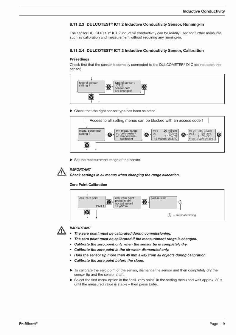
ProMinent® Page 119
Inductive Conductivity
8.11.2.3 DULCOTEST® ICT 2 Inductive Conductivity Sensor, Running-In
The sensor DULCOTEST® ICT 2 inductive conductivity can be readily used for further measures such as calibration and measurement without requiring any running-in.
8.11.2.4 DULCOTEST® ICT 2 Inductive Conductivity Sensor, Calibration
Presettings
Check fi rst that the sensor is correctly connected to the DULCOMETER® D1C (do not open the sensor).
� Check that the right sensor type has been selected.
type of sensorsetting ?
type of sensor : ICT 2sensor dataare changed!
� Set the measurement range of the sensor.
IMPORTANT
Check settings in all menus when changing the range allocation.
Zero Point Calibration
setting ?meas. parameter
Access to all setting menus can be blocked with an access code !
cc :mr :
15 mS/cm 23.8 °C
20 mS/cm1.120/cm
α : 2.10% °C
mr: meas. rangecc: cellconstantα: temperature-
coefficient
mr 2 : 200 μS/cmcc 2 : 1.120 /cmα: 2.10% /°C1106 μS/cm 25.0 °C
cali. zero point
PAR 1
cali. zero pointprobe in air!accept value?12 μS/cm
please wait!
= automatic timing
IMPORTANT
• The zero point must be calibrated during commissioning.
• The zero point must be calibrated if the measurement range is changed.
• Calibrate the zero point only when the sensor tip is completely dry.
• Calibrate the zero point in the air when dismantled only.
• Hold the sensor tip more than 40 mm away from all objects during calibration.
• Calibrate the zero point before the slope.
� To calibrate the zero point of the sensor, dismantle the sensor and then completely dry the sensor tip and the sensor shaft.
� Select the fi rst menu option in the “cali. zero point” in the setting menu and wait approx. 30 s until the measured value is stable – then press Enter.
BA_DR_001_02_09_GB.indd 119BA_DR_001_02_09_GB.indd 119 24.02.2009 12:24:08 Uhr24.02.2009 12:24:08 Uhr
ProMinent®Page 120
Slope Test
IMPORTANT
• Always follow the handling instructions below.
• During calibration the water sample must be fl owing evenly without bubbles or tur bu-lence or at a standstill.
• If calibrating in fl owing water, the electrolytic conductivity of the water sample must be constant.
• The axis through the bore of the sensor tip must line up with the direction of the fl ow.
� Cover the sensor tip completely with the water sample (immerse or fl ood the environment)
There are now three alternative procedures for different require ments:
Measurement Accuracy to within approx. 10 %
� Set the temperature coeffi cient � of the water sample in the “meas. parameter setting?” setting menu (related to 25 °C. Arrow keys.) or determine using the “calibration �” setting menu (see Operating instructions DULCOMETER® D1C, Inductive Con duc tiv i ty)
Inductive Conductivity
� Enter the sensor installation factor in the “install. factor” setting menu (arrow keys). The installation factor is “1” if the distance from the wall a of the sensor tip is greater than 30 mm.
High Measurement Accuracy
Calibration with Reference Metering Equipment
Calibration of the sensor is normally carried out once it has been installed with a reference metering device (e.g. a hand-held meter for conductive conductivity).
Measurement Accuracy of Reference Meter
The reference metering equipment must have a corresponding measurement accuracy (see operating instructions of the ref er ence metering equipment with respect to the measurement range and measurement accuracy for conductivity and temperature). In order to exploit the measurement accuracy of the sensor it must be calibrated to an accuracy of at least 1 %.
The reference metering equipment itself must be calibrated using calibration solutions with a measurement accuracy better than ±1 % (see operating instructions of the reference metering equip ment).
ProMinent recommends a reference metering device with a four-electrode sensor and a tempera-ture measurement accuracy better than ±0.5 °C at 25 °C (e.g. Portamess 911 Cond (order no. 1008713) with sensor type LF 204 (order no. 1008723)) for all measurements in conductivity range above 1 mS/cm.
CAUTION
Take suitable precautions when taking samples (safety gear ...)!
install. factorsetting ?
install. factor 0,5
100 μS/cm
BA_DR_001_02_09_GB.indd 120BA_DR_001_02_09_GB.indd 120 24.02.2009 12:24:08 Uhr24.02.2009 12:24:08 Uhr
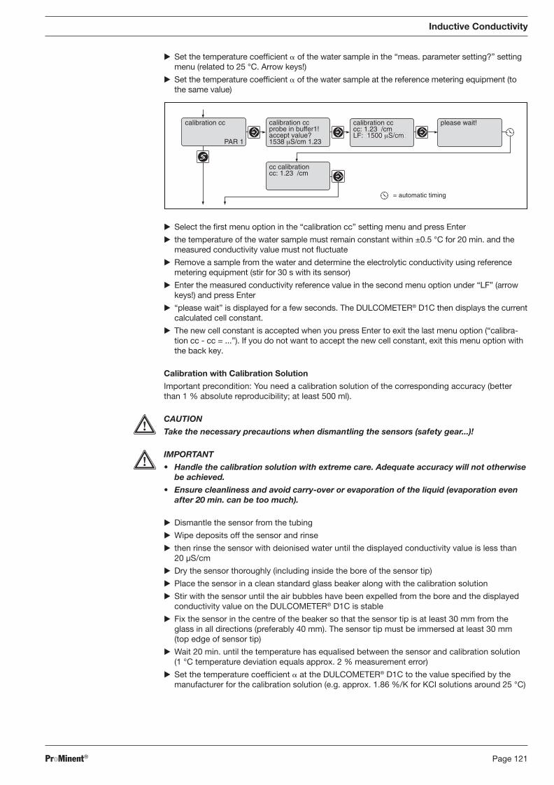
ProMinent® Page 121
Inductive Conductivity
� Set the temperature coeffi cient � of the water sample in the “meas. parameter setting?” setting menu (related to 25 °C. Arrow keys!)
� Set the temperature coeffi cient � of the water sample at the reference metering equipment (to the same value)
calibration ccprobe in buffer1!accept value?1538 μS/cm 1.23
calibration cc
PAR 1
please wait!
cc calibrationcc: 1.23 /cm
calibration cccc: 1.23 /cmLF: 1500 μS/cm
= automatic timing
� Select the fi rst menu option in the “calibration cc” setting menu and press Enter
� the temperature of the water sample must remain constant within ±0.5 °C for 20 min. and the measured conductivity value must not fl uctuate
� Remove a sample from the water and determine the electrolytic conductivity using reference metering equipment (stir for 30 s with its sensor)
� Enter the measured conductivity reference value in the second menu option under “LF” (arrow keys!) and press Enter
� “please wait” is displayed for a few seconds. The DULCOMETER® D1C then displays the current calculated cell constant.
� The new cell constant is accepted when you press Enter to exit the last menu option (“cal i bra-tion cc - cc = ...”). If you do not want to accept the new cell constant, exit this menu option with the back key.
Calibration with Calibration Solution
Important precondition: You need a calibration solution of the corresponding accuracy (better than 1 % absolute reproducibility; at least 500 ml).
CAUTION
Take the necessary precautions when dismantling the sensors (safety gear...)!
IMPORTANT
• Handle the calibration solution with extreme care. Adequate accuracy will not otherwise be achieved.
• Ensure cleanliness and avoid carry-over or evaporation of the liquid (evaporation even after 20 min. can be too much).
� Dismantle the sensor from the tubing
� Wipe deposits off the sensor and rinse
� then rinse the sensor with deionised water until the displayed conductivity value is less than 20 μS/cm
� Dry the sensor thoroughly (including inside the bore of the sensor tip)
� Place the sensor in a clean standard glass beaker along with the calibration solution
� Stir with the sensor until the air bubbles have been expelled from the bore and the displayed conductivity value on the DULCOMETER® D1C is stable
� Fix the sensor in the centre of the beaker so that the sensor tip is at least 30 mm from the glass in all directions (preferably 40 mm). The sensor tip must be immersed at least 30 mm (top edge of sensor tip)
� Wait 20 min. until the temperature has equalised between the sensor and calibration solution (1 °C temperature deviation equals approx. 2 % measurement error)
� Set the temperature coeffi cient � at the DULCOMETER® D1C to the value specifi ed by the manufacturer for the calibration solution (e.g. approx. 1.86 %/K for KCI solutions around 25 °C)
BA_DR_001_02_09_GB.indd 121BA_DR_001_02_09_GB.indd 121 24.02.2009 12:24:08 Uhr24.02.2009 12:24:08 Uhr
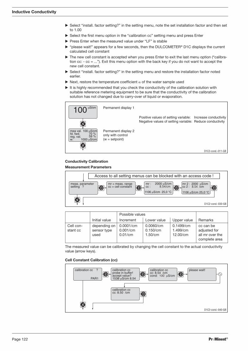
ProMinent®Page 122
Possible values
Initial value Increment Lower value Upper value Remarks
Cell con- depending on 0.0001/cm 0.0060/cm 0.1499/cm cc can be stant cc sensor type 0.001/cm 0.150/cm 1.499/cm adjusted for used 0.01/cm 1.50/cm 12.00/cm all mr over the complete area
The measured value can be calibrated by changing the cell constant to the actual conductivity value (arrow keys).
� Select “install. factor setting?” in the setting menu, note the set installation factor and then set to 1.00
� Select the fi rst menu option in the “calibration cc” setting menu and press Enter
� Press Enter when the measured value under “LF” is stable
� “please wait!” appears for a few seconds, then the DULCOMETER® D1C displays the current calculated cell constant
� The new cell constant is accepted when you press Enter to exit the last menu option (“calibra-tion cc: - cc = ...”). Exit this menu option with the back key if you do not want to accept the new cell constant.
� Select “install. factor setting?” in the setting menu and restore the installation factor noted earlier.
� Next, restore the temperature coeffi cient � of the water sample used
� It is highly recommended that you check the conductivity of the calibration solution with suitable reference metering equipment to be sure that the conductivity of the calibration solution has not changed due to carry-over of liquid or evaporation.
Inductive Conductivity
Conductivity Calibration
Measurement Parameters
100 μS/cm
Permanent display 2only with control(w = setpoint)
D1C2-cond.-011-GB
Permanent display 1
mea val.fd. fwd.reg. val.
70 %59 %
100 μS/cm
1000 μS/cmw:
Positive values of setting variable: Increase conductivityNegative values of setting variable: Reduce conductivity
D1C2-cond.-040-GB
calibration ccprobe in buffer!accept value?1538 μS/cm 8.54
calibration cc ?
PAR1
calibration cccc: 8.54 /cmcond: 100 μS/cm
calibration cccc: 8.50 /cm
please wait!
Cell Constant Calibration (cc)
D1C2-cond.-030-GB
Access to all setting menus can be blocked with an access code !
meas. parametersetting ?
mr = meas. rangecc = cell constant
2000 μS/cmcc :mr :
1106 μS/cm 25,0 °C
mr 2 : 2000 μS/cmcc 2 : 8.54 /cm
1106 μS/cm 25,0 °C
8.54/cm
BA_DR_001_02_09_GB.indd 122BA_DR_001_02_09_GB.indd 122 24.02.2009 12:24:08 Uhr24.02.2009 12:24:08 Uhr
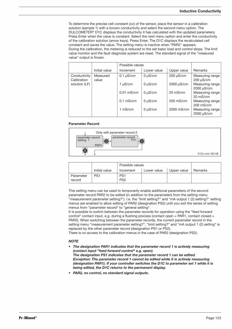
ProMinent® Page 123
To determine the precise cell constant (cc) of the sensor, place the sensor in a calibration so lu tion (sample 1) with a known conductivity and select the second menu option. The DULCOMETER® D1C displays the conductivity it has calculated with the updated parameters. Press Enter when the value is constant. Select the next menu option and enter the conductivity of the calibration solution (arrow keys). Press Enter. The D1C displays the recalculated cell constant and saves the value. The setting menu is inactive when “PAR2“ appears.
During the calibration, the metering is reduced to the set basic load and control stops. The limit value monitor and the fault diagnosis system are reset. The standard signal of the “measured value“ output is frozen.
Possible values
Initial value Increment Lower value Upper value Remarks
Conductivity Measured 0.1 μS/cm 0 μS/cm 200 μS/cm Measuring range Calibration value 200 μS/cm solution (LF) 1 μS/cm 0 μS/cm 2000 μS/cm Measuring range 2000 μS/cm 0.01 mS/cm 0 μS/cm 20 mS/cm Measuring range 20 mS/cm 0.1 mS/cm 0 μS/cm 200 mS/cm Measuring range 200 mS/cm 1 mS/cm 0 μS/cm 2000 mS/cm Measuring range 2000 μS/cm
Inductive Conductivity
Parameter Record
This setting menu can be used to temporarily enable additional parameters of the second parameter record PAR2 to be edited (in addition to the parameters from the setting menu “measurement parameter setting?“). I.e. the “limit setting?“ and “mA output 1 (2) setting?“ setting menus are enabled to allow editing of PAR2 (designation PS2) until you exit the series of setting menus from “parameter record“ to “general setting“.
It is possible to switch between the parameter records for operation using the “feed forward control“ contact input, e.g. during a fl ushing process (contact open = PAR1, contact closed = PAR2). When switching between the parameter records, the current parameter record in the setting menu “measurement parameter setting?”, “limit setting?“ and “mA output 1 (2) setting“ is replaced by the other parameter record (designation PS1 or PS2). There is no access to the calibration menus in the case of PAR2 (designation PS2).
NOTE
• The designation PAR1 indicates that the parameter record 1 is actively measuring (contact input “feed forward control“ e.g. open). The designation PS1 indicates that the parameter record 1 can be edited. Exception: The parameter record 1 cannot be edited while it is actively measuring (designation PAR1). If your controller switches the D1C to parameter set 1 while it is being edited, the D1C returns to the permanent display.
• PAR2, no control, no standard signal outputs.
Grenzwert2 oben 5.00 ppmGrenzwert1 unten 1.00 ppm
Only with parameter record 2
D1C2-cond.-042-GB
parameter recordsetting ?
PAR1
parameter recordPS1
Possible values
Initial value Increment Lower value Upper value Remarks
Parameter PS1 PS1 record PS2
BA_DR_001_02_09_GB.indd 123BA_DR_001_02_09_GB.indd 123 24.02.2009 12:24:08 Uhr24.02.2009 12:24:08 Uhr
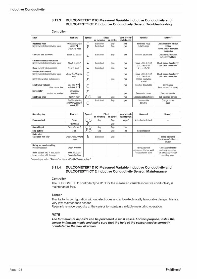
ProMinent®Page 124
Operating step Note text Symbol Effect Alarm with ack- Comment Remedy on metering on control nowledgement
Pause contact Pause Stop Stop no/yes* No further fault check –
Pause/Hold Stop
Control input Parameter set 2 Stop Stop no
Stop button Stop Stop Stop no Relay drops out –
Calibration Calibration with error Check measurement Basic load Stop – – Repeat calibration range Check sensor/calibration solution
During servomotor setting Position feedback Check direction Without correct Check potentiometer adjustment, the last valid and relay connection Upper position <40 % max. value Final value low values are still used Set correct servomotor Lower position >30 % range Final value high operating range
Error Fault text Symbol Effect Alarm with ack- Remarks Remedy on metering on control nowledgement
Measured value mS measurement Basic load Stop yes Measured value Check measured variable Signal exceeded/drops below value range Basic load Stop yes outside range setting Check mS input Check sensor and cable connection
Checkout time exceeded Check mS sensor Basic load Stop yes Function detachable Check sensor function, extend control time
Correction measured variable Signal exceeded/drops below value Check Te. input Basic load Stop yes Signal <3.8 ±0.2 mA Check sensor, transformer or >23 ±0.2 mA and cable connection Upper Te. limit value exceeded Te. limit value Basic load Stop yes at α ≥ 4 %/°C
Feed forward control Signal exceeded/drops below value Check feed forward yes Signal <3.0 ±0.2 mA Check sensor, transformer input or >23 ±0.2 mA and cable connection Signal below value, multiplicative " Stop yes The last valid value is used
Limit value violation mS-limit 1 yes Function detachable Defi ne cause after control time mS-limit 2 Reset values if necessary
Servomotor Servomotor position not reached defective yes Servomotor closes Check servomotor
Electronic error System error Stop Stop yes Electronic data defective Call customer service
LF cable defective, Basic load Stop yes Sensor cable Change sensor amplifi er defective, defective cable check SPI
8.11.3 DULCOMETER® D1C Measured Variable Inductive Conductivity and DULCOTEST® ICT 2 Inductive Conductivity Sensor, Troubleshooting
Controller
Inductive Conductivity
8.11.4 DULCOMETER® D1C Measured Variable Inductive Conductivity and DULCOTEST® ICT 2 Inductive Conductivity Sensor, Maintenance
Controller
The DULCOMETER® controller type D1C for the measured variable inductive conductivity is maintenance-free.
Sensor
Thanks to its confi guration without electrodes and a fl ow-technically favourable design, this is a very low-maintenance sensor. Regularly remove deposits at the sensor to maintain a reliable measuring operation.
NOTE
The formation of deposits can be prevented in most cases. For this purpose, install the sensor in fl owing media and make sure that the hole at the sensor head is correctly orientated to the fl ow direction.
* depending on wether “Alarm on” or “Alarm off” set in “General settings”.
BA_DR_001_02_09_GB.indd 124BA_DR_001_02_09_GB.indd 124 24.02.2009 12:24:08 Uhr24.02.2009 12:24:08 Uhr

ProMinent® Page 125
8.12 Measuring Parameter Fluoride
8.12.1 DULCOMETER® D1C Measured Variable Fluoride, Setting and Operation
Display Symbols The display of the DULCOMETER® D1C controller uses the following symbols:
Description Comment Symbol
Limit value transgression Symbol Relay 1, upper left
Symbol Relay 1, lower left
Symbol Relay 2, upper right
Symbol Relay 2, lower right
Metering pump 1 (Fluoride) Symbol Control off left
Symbol Control on left
Metering pump 2 (deFluor) Symbol Control off right
Symbol Control on right
Solenoid valve 1 (Fluoride) Symbol Control off left
Symbol Control on left
Solenoid valve 2 (deFluor) Symbol Control off right
Symbol Control on right
Servomotor Control, open relay
Control, close relay
Without control
The bar Position feedback increases from left to right during opening
Stop button pressed
Manual metering
Fault
Fluoride
BA_DR_001_02_09_GB.indd 125BA_DR_001_02_09_GB.indd 125 24.02.2009 12:24:08 Uhr24.02.2009 12:24:08 Uhr
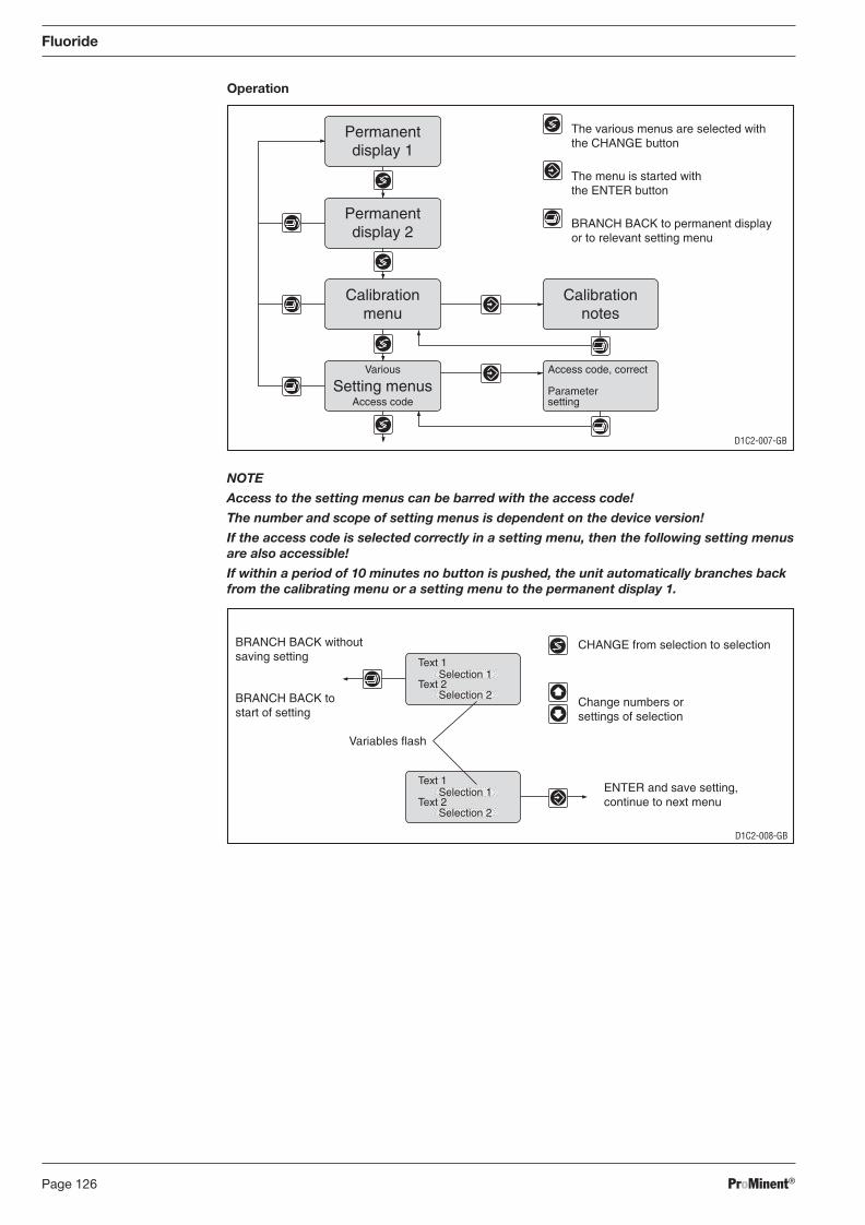
ProMinent®Page 126
Operation
Fluoride
NOTE
Access to the setting menus can be barred with the access code!
The number and scope of setting menus is dependent on the device version!
If the access code is selected correctly in a setting menu, then the following setting menus are also accessible!
If within a period of 10 minutes no button is pushed, the unit automatically branches back from the calibrating menu or a setting menu to the permanent display 1.
Calibrationnotes
Access code, correct
Parametersetting
Permanentdisplay 1
Permanentdisplay 2
Calibrationmenu
Various
Access codeSetting menus
D1C2-007-GB
The various menus are selected withthe CHANGE button
The menu is started withthe ENTER button
BRANCH BACK to permanent displayor to relevant setting menu
D1C2-008-GB
CHANGE from selection to selection
Change numbers orsettings of selection
Variables flash
ENTER and save setting,continue to next menu
BRANCH BACK withoutsaving setting
BRANCH BACK tostart of setting
Text 1
Text 2Selection 1
Selection 2
Text 1
Text 2Selection 1
Selection 2
BA_DR_001_02_09_GB.indd 126BA_DR_001_02_09_GB.indd 126 24.02.2009 12:24:08 Uhr24.02.2009 12:24:08 Uhr
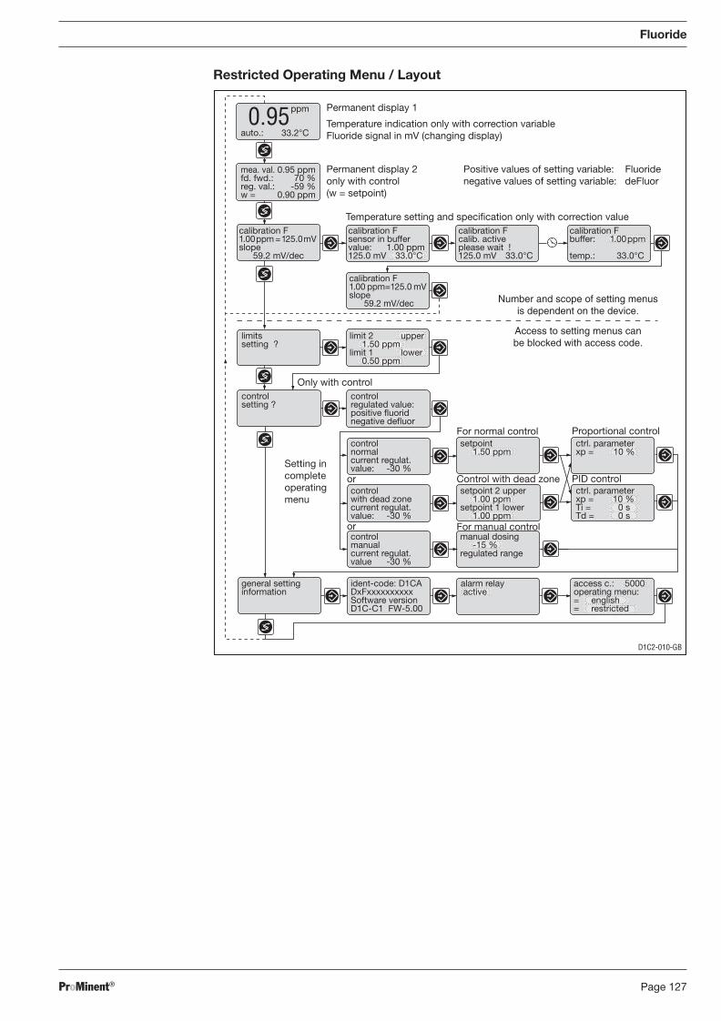
ProMinent® Page 127
Fluoride
Restricted Operating Menu / Layout
calibration F1.00ppm =125.0mVslope
59.2 mV/dec
Positive values of setting variable: Fluoridenegative values of setting variable: deFluor
Permanent display 2only with control(w = setpoint)
Temperature indication only with correction variableFluoride signal in mV (changing display)
0.95
D1C2-010-GB
ident-code: D1CADxFxxxxxxxxxxSoftware versionD1C-C1 FW-5.00
manual dosing -15 %regulated range
controlmanualcurrent regulat.value -30 %
calibration F1.00 ppm=125.0 mVslope
59.2 mV/dec
calibration Fbuffer: 1.00ppm
temp.: 33.0°C
calibration Fcalib. activeplease wait !125.0 mV 33.0°C
calibration Fsensor in buffervalue: 1.00 ppm125.0 mV 33.0°C
mea. val. 0.95 ppmfd. fwd.: 70 %reg. val.: -59 %w = 0.90 ppm
Permanent display 1
auto.: 33.2°C
ppm
Temperature setting and specification only with correction value
For normal control Proportional control
Only with control
limitssetting ?
controlsetting ?
controlregulated value:positive fluoridnegative defluor
controlnormalcurrent regulat.value: -30 %
controlwith dead zonecurrent regulat.value: -30 %
setpoint 1.50 ppm
setpoint 2 upper 1.00 ppmsetpoint 1 lower 1.00 ppm
ctrl. parameterxp = 10 %
ctrl. parameterxp = 10 %Ti = 0 sTd = 0 s
Control with dead zone PID control
general settinginformation
Setting incompleteoperatingmenu
For manual control
alarm relay active
access c.: 5000operating menu:= english= restricted
or
or
limit 1 lower 0.50 ppm
limit 2 upper 1.50 ppm
Number and scope of setting menusis dependent on the device.
Access to setting menus canbe blocked with access code.
BA_DR_001_02_09_GB.indd 127BA_DR_001_02_09_GB.indd 127 24.02.2009 12:24:08 Uhr24.02.2009 12:24:08 Uhr
ProMinent®Page 128
Clamps Measuring Transducer Clamps D1C
X1:1 + sensor cable (mA signal) X2:9
X1:2 - sensor cable (mA signal) X2:10
X2:1
X2:2 bridge
reference electrode
8.12.2 Fluoride Sensor FLEP 010 SE/FLEP 0100 SE, Commissioning
8.12.2.1 Fluoride Sensor FLEP 010 SE/FLEP 0100 SE, Assembly
Assembly
IMPORTANT
• The LaF3 crystal must not be soiled!
• The LaF3 crystal must not be scratched or touched by hand!
• When screwing on the measuring transducer, always hold the sensor by its head - never on the shaft!
• When dipping the sensor into the measuring water take care that no gas bubbles adhere to the LaF3 crystal!
Unscrew the blanking cap on the measuring vessel DLG IV, screw down the sensor and fasten it using a 17 mm spanner.
Screw down the reference electrode REFP-SE (part no.1018458) into the adjacent opening of the DLG IV. For measurements with automatic temperature correction, screw down a PT 100 into one of the remaining openings.
Measuring Transducer, Assembly
IMPORTANT
• The device must not be used without further protection (outer casing, weather pro tec-tion roof) in outdoor applications.
• The interior of the measuring transducer must be protected against moisture during installation!
• Screw the measuring transducer by hand down to the stop on the sensor. Never screw down the measuring transducer in any other way!
• When screwing-on the measuring transducer, always hold the sensor by its head - never on the shaft!
• Proceed cautiously when screwing the measuring transducer onto sensors made by other manufacturers, to avoid crossing the threads!
• Incorrect connection of the measuring transducer to the sensor can lead to a falsifi ed output signal!
• Operate the sensor with the reference electrode only within the specifi ed measuring range of the measuring transducer!
• When the potential measuring range of the measuring transducer is exceeding due to too high fl uoride concentrations, the output signal of the measuring transducer remains fi xed at 3.2 mA irrespective of the true concentration. The measuring device would than indicate too low a concentration!
• When evaluating the output signal of the measuring transducer using a PLC device or a computer pay attention to the logarithmic relation between the output signal and the fl uoride concentration! (cf. operating instruction of the sensor)
Connecting to ProMinent® units DULCOMETER® D1C � Release the clamp screw of the PG cable union (only the clamp screw!)
� Turn the upper part of the measuring transducer through a quarter turn in the counter-clock-wise direction and then pull it off (bayonet fi tting).
� Insert the 2-wire sensor cable into the PG cable union. If necessary, dust the cable with talcum powder to aid fi tting.
� Strip the cable ends and clamp 0.25 mm cable sleeves onto the stripped cable ends.
� Connect the cable ends to the terminals 1 and 2:
Fluoride
BA_DR_001_02_09_GB.indd 128BA_DR_001_02_09_GB.indd 128 24.02.2009 12:24:09 Uhr24.02.2009 12:24:09 Uhr
ProMinent® Page 129
Fluoride
� Tighten the clamping screw of the PG cable union
� Push the top section into the middle section as far as it will go and then carefully turn it in the clockwise direction until it reaches the stop (take care not to break off the pins on the bayonet fi tting).
� Screw the measuring transducer by hand down to the stop on the sensor.
� Screw the SN6-socket onto the reference electrode.
� Determine the standard potential and make the slope adjustment (calibration) on the control unit (cf. operating instructions there).
8.12.2.2 Fluoride Sensor FLEP 010 SE/FLEP 0100 SE, Electrical Installation
IMPORTANT
Before using a potential compensation pin, contact ProMinent Dosiertechnik GmbH! Otherwise the sensor can be damaged irreversibly.
Make sure that the SN6 contacts on the sensor and the transducer resp. are clean and dry. Screw down the transducer 4 … 20 mA FP V1 or FP 100 V1 onto the sensor by hand. Screw down the SN6 plug of the transducer measuring cable onto the reference electrode.
8.12.2.3 Fluoride Sensor FLEP 010 SE/FLEP 0100 SE, Running-In
Running-In Period of the Sensor
Allow the sensor to run in for 1 h at minimum 0.4 ppm F–.
8.12.2.4 Fluoride Sensor FLEP 010 SE/FLEP 0100 SE, Calibration
IMPORTANT
• The sensor must be checked regularly and if necessary calibrated!
• Observe legal requirements in force!
• Before the fi rst calibration the sensor must be run in!
• Obey the instruction manual of the measuring instrument!
• Carry out a two-point calibration at fi rst start-up!
For calibration the sensor, the reference electrode and - if present – the PT 100 must be im mersed in the calibration solution. During calibration the solution must be uniformly stirred by a magnetic stirrer. For faster potential equilibration the solution must have a conductivity > 1000 μS/cm (e.g. by using a corresponding Na2SO4 solution, e.g., 1 g/l). For the determination of the slope (two-point calibration), the two calibration solutions must differ in their fl uoride content by at least 0.5 ppm. The two-point calibration has to be performed less often than the one-point calibration.
BA_DR_001_02_09_GB.indd 129BA_DR_001_02_09_GB.indd 129 24.02.2009 12:24:09 Uhr24.02.2009 12:24:09 Uhr
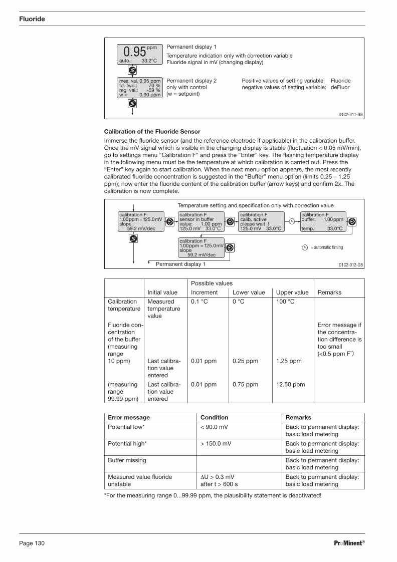
ProMinent®Page 130
Fluoride
D1C2-012-GBPermanent display 1
= automatic timing
calibration F1.00ppm =125.0mVslope
59.2 mV/dec
calibration F1.00ppm = 125.0mVslope
59.2 mV/dec
calibration Fbuffer: 1.00ppm
temp.: 33.0°C
calibration Fcalib. activeplease wait !125.0 mV 33.0°C
calibration Fsensor in buffervalue: 1.00 ppm125.0 mV 33.0°C
Temperature setting and specification only with correction value
Temperature indication only with correction variableFluoride signal in mV (changing display)
D1C2-011-GB
Positive values of setting variable: Fluoridenegative values of setting variable: deFluor
Permanent display 2only with control(w = setpoint)
0.95
mea. val. 0.95 ppmfd. fwd.: 70 %reg. val.: -59 %w = 0.90 ppm
Permanent display 1
auto.: 33.2°C
ppm
Possible values
Initial value Increment Lower value Upper value Remarks
Calibration Measured 0.1 °C 0 °C 100 °C temperature temperature value
Fluoride con- Error message if centration the concentra- of the buffer tion difference is (measuring too small range (<0.5 ppm F–)10 ppm) Last calibra- 0.01 ppm 0.25 ppm 1.25 ppm tion value entered
(measuring Last calibra- 0.01 ppm 0.75 ppm 12.50 ppm range tion value 99.99 ppm) entered
Error message Condition Remarks
Potential low* < 90.0 mV Back to permanent display: basic load metering
Potential high* > 150.0 mV Back to permanent display: basic load metering
Buffer missing Back to permanent display: basic load metering
Measured value fl uoride ΔU > 0.3 mV Back to permanent display: unstable after t > 600 s basic load metering
*For the measuring range 0...99.99 ppm, the plausibility statement is deactivated!
Calibration of the Fluoride Sensor
Immerse the fl uoride sensor (and the reference electrode if applicable) in the calibration buffer. Once the mV signal which is visible in the changing display is stable (fl uctuation < 0.05 mV/min), go to settings menu “Calibration F” and press the “Enter” key. The fl ashing temperature display in the following menu must be the temperature at which calibration is carried out. Press the “Enter” key again to start calibration. When the next menu option appears, the most recently calibrated fl uoride concentration is suggested in the “Buffer” menu option (limits 0.25 – 1.25 ppm); now enter the fl uoride content of the calibration buffer (arrow keys) and confi rm 2x. The calibration is now complete.
BA_DR_001_02_09_GB.indd 130BA_DR_001_02_09_GB.indd 130 24.02.2009 12:24:09 Uhr24.02.2009 12:24:09 Uhr
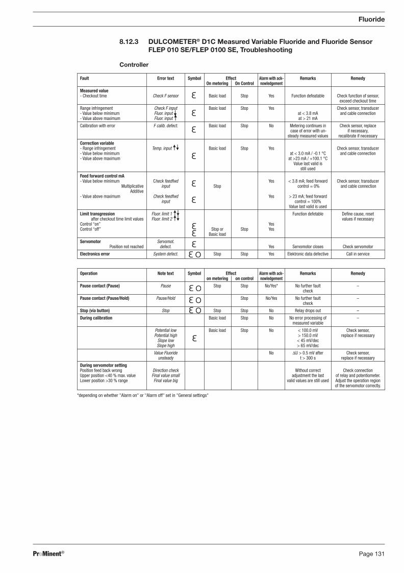
ProMinent® Page 131
Fault Error text Symbol Effect Alarm with ack- Remarks Remedy On metering On Control nowledgement
Measured value - Checkout time Check F sensor Basic load Stop Yes Function defeatable Check function of sensor, exceed checkout time
Range infringement Check F input Basic load Stop Yes Check sensor, transducer - Value below minimum Fluor. input at < 3.8 mA and cable connection - Value above maximum Fluor. input at > 21 mA
Calibration with error F calib. defect. Basic load Stop No Metering continues in Check sensor, replace case of error with un- if necessary, steady measured values recalibrate if necessary
Correction variable - Range infringement Temp. input Basic load Stop Yes Check sensor, transducer - Value below minimum at < 3.0 mA / -0.1 °C and cable connection - Value above maximum at >23 mA / +100.1 °C Value last valid is still used
Feed forward control mA - Value below minimum Check feedfwd Yes < 3.8 mA; feed forward Check sensor, transducer Multiplicative input Stop control = 0% and cable connection Additive - Value above maximum Check feedfwd Yes > 23 mA; feed forward input control = 100% Value last valid is used
Limit transgression Fluor. limit 1 Function defetable Defi ne cause, reset after checkout time limit values Fluor. limit 2 values if necessary Control “on” Yes Control “off” Stop or Stop Yes Basic load
Servomotor Servomot. Position not reached defect. Yes Servomotor closes Check servomotor
Electronics error System defect. Stop Stop Yes Elektronic data defective Call in service
Operation Note text Symbol Effect Alarm with ack- Remarks Remedy on metering on control nowledgement
Pause contact (Pause) Pause Stop Stop No/Yes* No further fault – check
Pause contact (Pause/Hold) Pause/Hold Stop No/Yes No further fault – check
Stop (via button) Stop Stop Stop No Relay drops out –
During calibration Basic load Stop No No error processing of – measured variable
Potential low Basic load Stop No < 100.0 mV Check sensor, Potential high > 150.0 mV replace if necessary Slope low < 45 mV/dec Slope high > 65 mV/dec
Value Fluoride No ΔU > 0.5 mV after Check sensor, unsteady t > 300 s replace if necessary
During servomotor setting Position feed back wrong Direction check Without correct Check connection Upper position <40 % max. value Final value small adjustment the last of relay and potentiometer. Lower position >30 % range Final value big valid values are still used Adjust the operation region of the servomotor correctly.
8.12.3 DULCOMETER® D1C Measured Variable Fluoride and Fluoride Sensor FLEP 010 SE/FLEP 0100 SE, Troubleshooting
Controller
Fluoride
*depending on whether "Alarm on" or "Alarm off" set in "General settings"
BA_DR_001_02_09_GB.indd 131BA_DR_001_02_09_GB.indd 131 24.02.2009 12:24:09 Uhr24.02.2009 12:24:09 Uhr
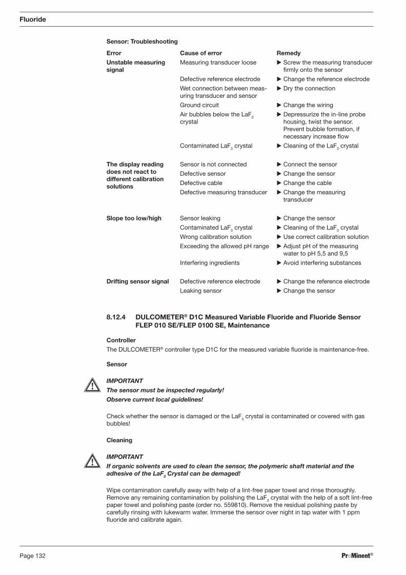
ProMinent®Page 132
Sensor: Troubleshooting
Fluoride
Error
Unstable measuring signal
The display reading does not react to different calibration
solutions
Slope too low/high
Drifting sensor signal
Cause of error
Measuring transducer loose
Defective reference electrode
Wet connection between meas-uring transducer and sensor
Ground circuit
Air bubbles below the LaF3 crystal
Contaminated LaF3 crystal
Sensor is not connected
Defective sensor
Defective cable
Defective measuring transducer
Sensor leaking
Contaminated LaF3 crystal
Wrong calibration solution
Exceeding the allowed pH range
Interfering ingredients
Defective reference electrode
Leaking sensor
Remedy
� Screw the measuring transducer fi rmly onto the sensor
� Change the reference electrode
� Dry the connection
� Change the wiring
� Depressurize the in-line probe housing, twist the sensor. Prevent bubble formation, if necessary increase fl ow
� Cleaning of the LaF3 crystal
� Connect the sensor
� Change the sensor
� Change the cable
� Change the measuring transducer
� Change the sensor
� Cleaning of the LaF3 crystal
� Use correct calibration solution
� Adjust pH of the measuring water to pH 5,5 and 9,5
� Avoid interfering substances
� Change the reference electrode
� Change the sensor
8.12.4 DULCOMETER® D1C Measured Variable Fluoride and Fluoride Sensor FLEP 010 SE/FLEP 0100 SE, Maintenance
Controller
The DULCOMETER® controller type D1C for the measured variable fl uoride is maintenance-free.
Sensor
IMPORTANT
The sensor must be inspected regularly!
Observe current local guidelines!
Check whether the sensor is damaged or the LaF3 crystal is contaminated or covered with gas bubbles!
Cleaning
IMPORTANT
If organic solvents are used to clean the sensor, the polymeric shaft material and the adhesive of the LaF3 Crystal can be demaged!
Wipe contamination carefully away with help of a lint-free paper towel and rinse thoroughly. Remove any remaining contamination by polishing the LaF3 crystal with the help of a soft lint-free paper towel and polishing paste (order no. 559810). Remove the residual polishing paste by carefully rinsing with lukewarm water. Immerse the sensor over night in tap water with 1 ppm fl uoride and calibrate again.
BA_DR_001_02_09_GB.indd 132BA_DR_001_02_09_GB.indd 132 24.02.2009 12:24:09 Uhr24.02.2009 12:24:09 Uhr
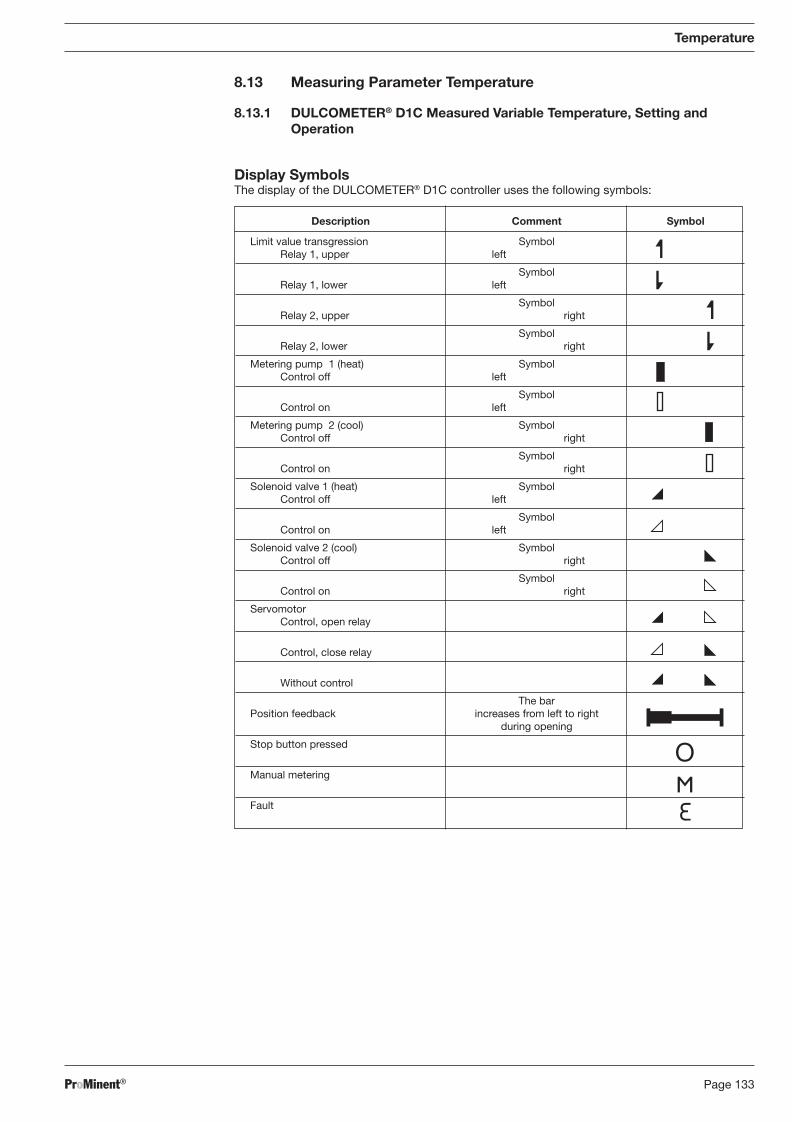
ProMinent® Page 133
Description Comment Symbol
Limit value transgression Symbol Relay 1, upper left
Symbol Relay 1, lower left
Symbol Relay 2, upper right
Symbol Relay 2, lower right
Metering pump 1 (heat) Symbol Control off left
Symbol Control on left
Metering pump 2 (cool) Symbol Control off right
Symbol Control on right
Solenoid valve 1 (heat) Symbol Control off left
Symbol Control on left
Solenoid valve 2 (cool) Symbol Control off right
Symbol Control on right
Servomotor Control, open relay
Control, close relay
Without control
The bar Position feedback increases from left to right during opening
Stop button pressed
Manual metering
Fault
8.13 Measuring Parameter Temperature
8.13.1 DULCOMETER® D1C Measured Variable Temperature, Setting and Operation
Display Symbols The display of the DULCOMETER® D1C controller uses the following symbols:
Temperature
BA_DR_001_02_09_GB.indd 133BA_DR_001_02_09_GB.indd 133 24.02.2009 12:24:09 Uhr24.02.2009 12:24:09 Uhr
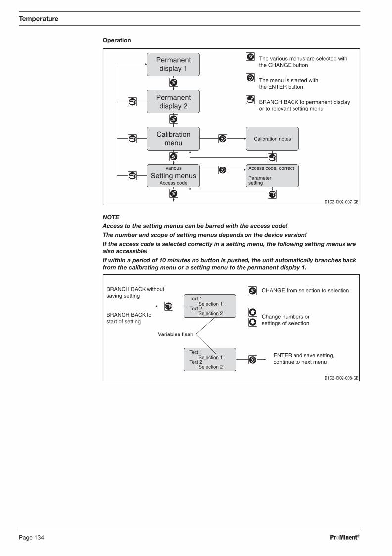
ProMinent®Page 134
Temperature
Operation
NOTE
Access to the setting menus can be barred with the access code!
The number and scope of setting menus depends on the device version!
If the access code is selected correctly in a setting menu, the following setting menus are also accessible!
If within a period of 10 minutes no button is pushed, the unit automatically branches back from the calibrating menu or a setting menu to the permanent display 1.
Access code, correct
Parametersetting
Calibration notes
Permanentdisplay 1
Permanentdisplay 2
Calibrationmenu
Various
Access codeSetting menus
The various menus are selected withthe CHANGE button
The menu is started withthe ENTER button
BRANCH BACK to permanent displayor to relevant setting menu
CHANGE from selection to selection
Change numbers orsettings of selection
Variables flash
ENTER and save setting,continue to next menu
BRANCH BACK withoutsaving setting
BRANCH BACK tostart of setting
Text 1
Text 2Selection 1
Selection 2
Text 1
Text 2Selection 1
Selection 2
D1C2-CIO2-007-GB
D1C2-CIO2-008-GB
BA_DR_001_02_09_GB.indd 134BA_DR_001_02_09_GB.indd 134 24.02.2009 12:24:09 Uhr24.02.2009 12:24:09 Uhr
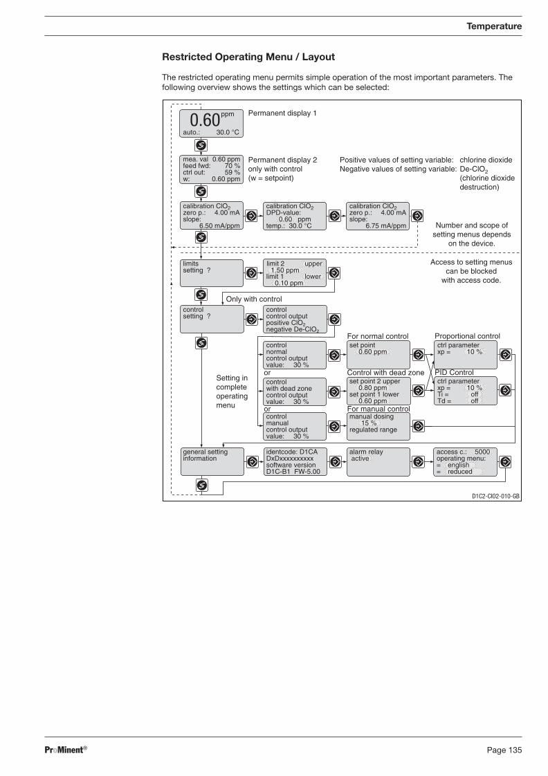
ProMinent® Page 135
Restricted Operating Menu / Layout
The restricted operating menu permits simple operation of the most important parameters. The following overview shows the settings which can be selected:
Temperature
Positive values of setting variable: chlorine dioxideNegative values of setting variable: De-ClO2
(chlorine dioxidedestruction)
auto.: 30.0 °C
Permanent display 1
Permanent display 2only with control(w = setpoint)
Control with dead zone
For normal control
PID Control
Proportional control
Only with control
ppm0.60
mea. val 0.60 ppmfeed fwd: 70 %ctrl out: 59 %w: 0.60 ppm
calibration ClO2zero p.: 4.00 mAslope:
6.50 mA/ppm
calibration ClO2DPD-value:
0.60 ppmtemp.: 30.0 °C
calibration ClO2zero p.: 4.00 mAslope:
6.75 mA/ppm
limitssetting ?
controlsetting ?
controlnormalcontrol outputvalue: 30 %
set point0.60 ppm
ctrl parameterxp = 10 %
controlwith dead zonecontrol outputvalue: 30 %
set point 2 upper0.80 ppm
set point 1 lower0.60 ppm
controlmanualcontrol outputvalue: 30 %
manual dosing15 %
regulated range
general settinginformation
identcode: D1CADxDxxxxxxxxxxsoftware versionD1C-B1 FW-5.00
alarm relay active
access c.: 5000operating menu:= english= reduced
Access to setting menuscan be blocked
with access code.
Setting incompleteoperatingmenu For manual control
or
or
ctrl parameterxp = 10 %Ti = offTd = off
limit 1 lower0.10 ppm
limit 2 upper1.50 ppm
Number and scope ofsetting menus depends
on the device.
controlcontrol outputpositive ClO2negative De-ClO2
D1C2-CIO2-010-GB
BA_DR_001_02_09_GB.indd 135BA_DR_001_02_09_GB.indd 135 24.02.2009 12:24:09 Uhr24.02.2009 12:24:09 Uhr
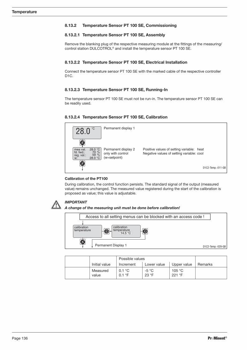
ProMinent®Page 136
14.5 °C
Permanent Display 1
calibrationtemperature
calibrationtemperature
Access to all setting menus can be blocked with an access code !
Temperature
8.13.2 Temperature Sensor PT 100 SE, Commissioning
8.13.2.1 Temperature Sensor PT 100 SE, Assembly
Remove the blanking plug of the respective measuring module at the fi ttings of the measuring/control station DULCOTROL® and install the temperature sensor PT 100 SE.
8.13.2.2 Temperature Sensor PT 100 SE, Electrical Installation
Connect the temperature sensor PT 100 SE with the marked cable of the respective controller D1C.
8.13.2.3 Temperature Sensor PT 100 SE, Running-In
The temperature sensor PT 100 SE must not be run-in. The temperature sensor PT 100 SE can be readily used.
8.13.2.4 Temperature Sensor PT 100 SE, Calibration
Calibration of the PT100
During calibration, the control function persists. The standard signal of the output (measured value) remains unchanged. The measured value registered during the start of the calibration is proposed as value; this value is adjustable.
IMPORTANT
A change of the measuring unit must be done before calibration!
Permanent display 1
w:
mea val. Permanent display 2only with control(w=setpoint)
fd. fwd.:reg. val.:
Positive values of setting variable: heatNegative values of setting variable: cool
°C28.0
28.0 °C
28.0 °C
70 %59 %
D1C2-Temp.-029-GB
D1C2-Temp.-011-GB
Possible values
Initial value Increment Lower value Upper value Remarks
Measured 0.1 °C -5 °C 105 °C value 0.1 °F 23 °F 221 °F
BA_DR_001_02_09_GB.indd 136BA_DR_001_02_09_GB.indd 136 24.02.2009 12:24:09 Uhr24.02.2009 12:24:09 Uhr
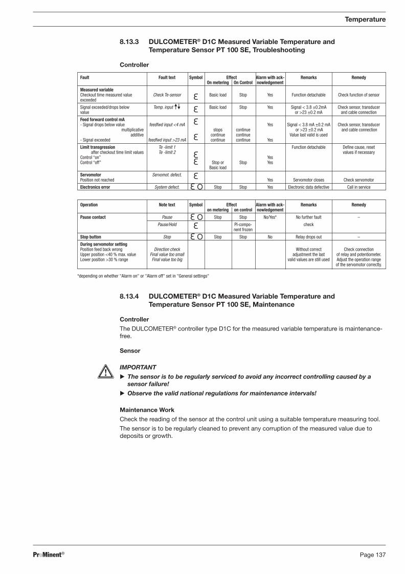
ProMinent® Page 137
Operation Note text Symbol Effect Alarm with ack- Remarks Remedy on metering on control nowledgement
Pause contact Pause Stop Stop No/Yes* No further fault –
Pause/Hold PI-compo- check nent frozen
Stop button Stop Stop Stop No Relay drops out –
During servomotor setting Position feed back wrong Direction check Without correct Check connection Upper position <40 % max. value Final value too small adjustment the last of relay and potentiometer. Lower position >30 % range Final value too big valid values are still used Adjust the operation range of the servomotor correctly.
Fault Fault text Symbol Effect Alarm with ack- Remarks Remedy On metering On Control nowledgement
Measured variable Checkout time measured value Check Te-sensor Basic load Stop Yes Function detachable Check function of sensor exceeded
Signal exceeded/drops below Temp. input Basic load Stop Yes Signal < 3.8 ±0.2mA Check sensor, transducer value or >23 ±0.2 mA and cable connection
Feed forward control mA - Signal drops below value feedfwd input <4 mA Yes Signal < 3.8 mA ±0.2 mA Check sensor, transducer multiplicative stops continue or >23 ±0.2 mA and cable connection additive continue continue Value last valid is used - Signal exceeded feedfwd input >23 mA continue continue Yes
Limit transgression Te -limit 1 Function detachable Defi ne cause, reset after checkout time limit values Te -limit 2 values if necessary Control “on” Yes Control “off” Stop or Stop Yes Basic load
Servomotor Servomot. defect. Position not reached Yes Servomotor closes Check servomotor
Electronics error System defect. Stop Stop Yes Electronic data defective Call in service
8.13.3 DULCOMETER® D1C Measured Variable Temperature and Temperature Sensor PT 100 SE, Troubleshooting
Controller
Temperature
8.13.4 DULCOMETER® D1C Measured Variable Temperature and Temperature Sensor PT 100 SE, Maintenance
Controller
The DULCOMETER® controller type D1C for the measured variable temperature is maintenance-free.
Sensor
IMPORTANT
� The sensor is to be regularly serviced to avoid any incorrect controlling caused by a sensor failure!
� Observe the valid national regulations for maintenance intervals!
Maintenance Work
Check the reading of the sensor at the control unit using a suitable temperature measuring tool.
The sensor is to be regularly cleaned to prevent any corruption of the measured value due to deposits or growth.
*depending on whether "Alarm on" or "Alarm off" set in "General settings"
BA_DR_001_02_09_GB.indd 137BA_DR_001_02_09_GB.indd 137 24.02.2009 12:24:09 Uhr24.02.2009 12:24:09 Uhr
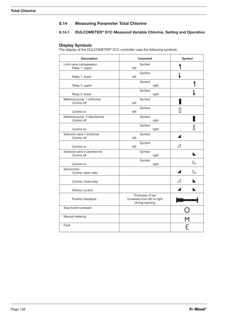
ProMinent®Page 138
8.14 Measuring Parameter Total Chlorine
8.14.1 DULCOMETER® D1C Measured Variable Chlorine, Setting and Operation
Display Symbols The display of the DULCOMETER® D1C controller uses the following symbols:
Description Comment Symbol
Limit value transgression Symbol Relay 1, upper left
Symbol Relay 1, lower left
Symbol Relay 2, upper right
Symbol Relay 2, lower right
Metering pump 1 (chlorine) Symbol Control off left
Symbol Control on left
Metering pump 2 (dechlorine) Symbol Control off right
Symbol Control on right
Solenoid valve 1 (chlorine) Symbol Control off left
Symbol Control on left
Solenoid valve 2 (dechlorine) Symbol Control off right
Symbol Control on right
Servomotor Control, open relay
Control, close relay
Without control
Thickness of bar Position feedback increases from left to right during opening
Stop button pressed
Manual metering
Fault
Total Chlorine
BA_DR_001_02_09_GB.indd 138BA_DR_001_02_09_GB.indd 138 24.02.2009 12:24:09 Uhr24.02.2009 12:24:09 Uhr
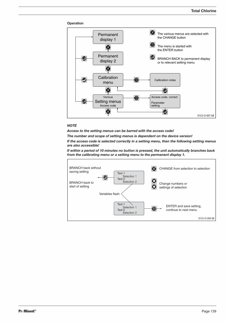
ProMinent® Page 139
Operation
Total Chlorine
NOTE
Access to the setting menus can be barred with the access code!
The number and scope of setting menus is dependent on the device version!
If the access code is selected correctly in a setting menu, then the following setting menus are also accessible!
If within a period of 10 minutes no button is pressed, the unit automatically branches back from the calibrating menu or a setting menu to the permanent display 1.
D1C2-Cl-008-GB
CHANGE from selection to selection
Change numbers orsettings of selection
Variables flash
ENTER and save setting,continue to next menu
BRANCH back withoutsaving setting
BRANCH back tostart of setting
Text 1
Text 2Selection 1
Selection 2
Text 1
Text 2Selection 1
Selection 2
Access code, correct
Parametersetting
Calibration notes
Permanentdisplay 1
Permanentdisplay 2
Calibrationmenu
Various
Access codeSetting menus
D1C2-Cl-007-GB
The various menus are selected withthe CHANGE button
The menu is started withthe ENTER button
BRANCH BACK to permanent displayor to relevant setting menu
BA_DR_001_02_09_GB.indd 139BA_DR_001_02_09_GB.indd 139 24.02.2009 12:24:10 Uhr24.02.2009 12:24:10 Uhr
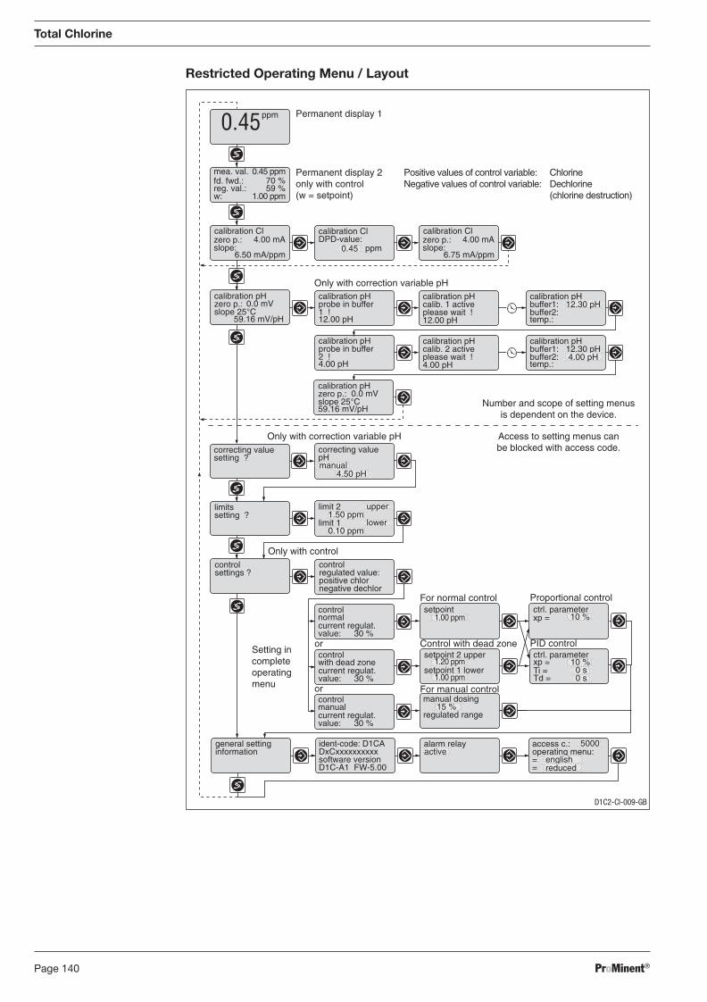
ProMinent®Page 140
Total Chlorine
Restricted Operating Menu / Layout
33.0°C 33.0°C
calibration pHprobe in buffer2 !4.00 pH
calibration pHcalib. 2 activeplease wait !4.00 pH
calibration pHbuffer1:buffer2:temp.:
12.30 pH
Only with correction variable pHcorrecting valuesetting ?
correcting valuepH
limit 21.50 ppm
upperlimitssetting ?
Control with dead zone
For normal control
PID control
Proportional controlsetpoint
1.00 ppm
setpoint 2 upper ctrl. parameter
Ti =Td =
xp =setpoint 1 lower
10 %
ctrl. parameterxp = 10 %
controlsettings ?
Only with controlcontrol
positive chlorregulated value:
negative dechlor
manual dosing
control
current regulat.value: 30 %
normal
15 %regulated range
general settinginformation
ident-code: D1CA
software versionDxCxxxxxxxxxx
D1C-A1 FW-5.00
alarm relay access c.:
==
operating menu:active5000
english
1.20 ppm
1.00 ppm
calibration pHzero p.:slope 25°C
0.0 mV
59.16 mV/pH
control
current regulat.value: 30 %
with dead zone
control
current regulat.value: 30 %
manual
Setting incompleteoperatingmenu
or
or For manual control
reduced
4.00 pH
4.50 pH
limit 10.10 ppm
lower
Permanent display 1
Permanent display 2only with control(w = setpoint)
ppm0.45
calibration Cl calibration ClDPD-value:
0.45
mea. val.fd. fwd.:reg. val.:
0.45 ppm
w: 1.00 ppm
ppm
70 %59 %
zero p.:slope:
4.00 mA
6.50 mA/ppm
Positive values of control variable:Negative values of control variable:
calibration Clzero p.:slope:
4.00 mA
6.75 mA/ppm
ChlorineDechlorine(chlorine destruction)
Only with correction variable pH
33.0°C 33.0°C
calibration pHzero p.:slope 25°C
0.0 mV
59.16 mV/pH
calibration pHprobe in buffer1 !12.00 pH
calibration pHcalib. 1 activeplease wait !12.00 pH
calibration pHbuffer1:buffer2:temp.:
12.30 pH
manual
0 s0 s
Number and scope of setting menusis dependent on the device.
Access to setting menus canbe blocked with access code.
D1C2-Cl-009-GB
BA_DR_001_02_09_GB.indd 140BA_DR_001_02_09_GB.indd 140 24.02.2009 12:24:10 Uhr24.02.2009 12:24:10 Uhr
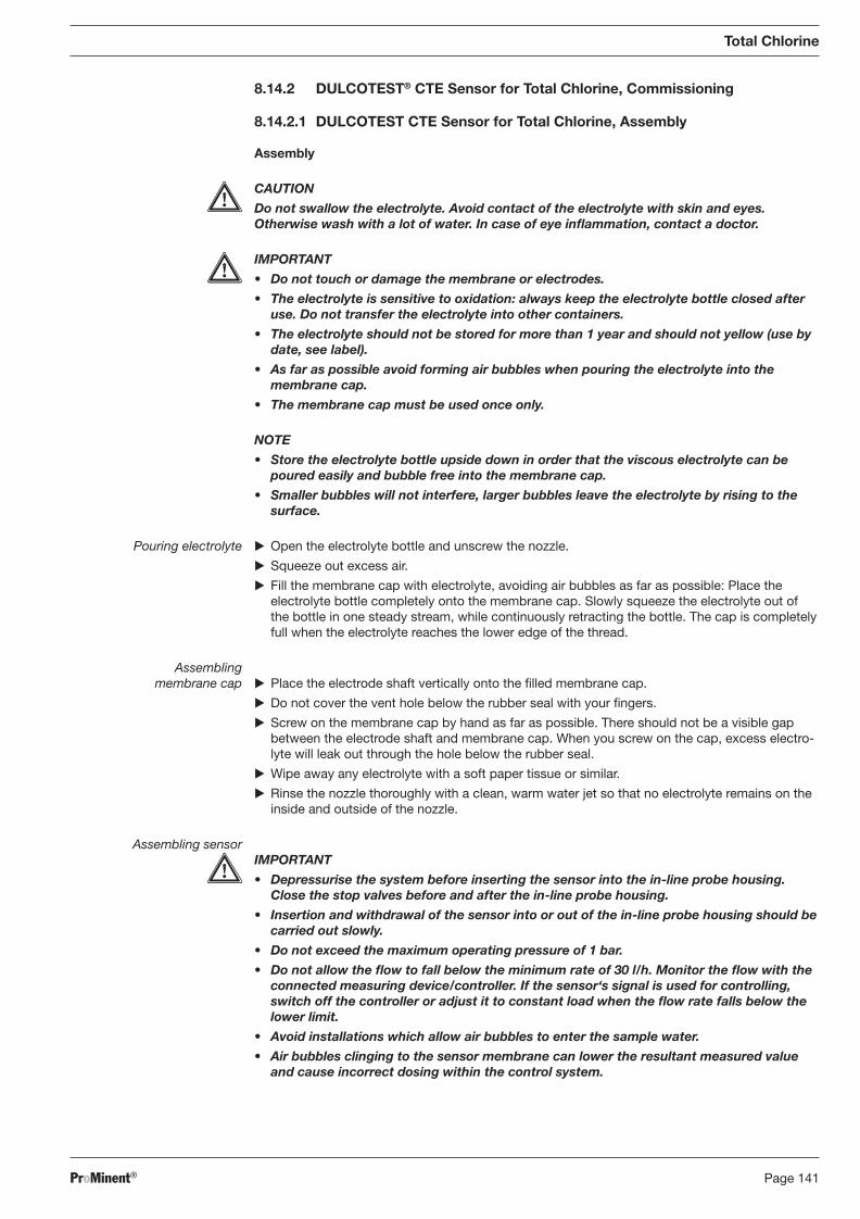
ProMinent® Page 141
8.14.2 DULCOTEST® CTE Sensor for Total Chlorine, Commissioning
8.14.2.1 DULCOTEST CTE Sensor for Total Chlorine, Assembly
Assembly
CAUTION
Do not swallow the electrolyte. Avoid contact of the electrolyte with skin and eyes. Otherwise wash with a lot of water. In case of eye infl ammation, contact a doctor.
IMPORTANT
• Do not touch or damage the membrane or electrodes.
• The electrolyte is sensitive to oxidation: always keep the electrolyte bottle closed after use. Do not transfer the electrolyte into other containers.
• The electrolyte should not be stored for more than 1 year and should not yellow (use by date, see label).
• As far as possible avoid forming air bubbles when pouring the electrolyte into the membrane cap.
• The membrane cap must be used once only.
NOTE
• Store the electrolyte bottle upside down in order that the viscous electrolyte can be poured easily and bubble free into the membrane cap.
• Smaller bubbles will not interfere, larger bubbles leave the electrolyte by rising to the surface.
Pouring electrolyte � Open the electrolyte bottle and unscrew the nozzle.
� Squeeze out excess air.
� Fill the membrane cap with electrolyte, avoiding air bubbles as far as possible: Place the electrolyte bottle completely onto the membrane cap. Slowly squeeze the electrolyte out of the bottle in one steady stream, while continuously retracting the bottle. The cap is completely full when the electrolyte reaches the lower edge of the thread.
Assembling membrane cap � Place the electrode shaft vertically onto the fi lled membrane cap.
� Do not cover the vent hole below the rubber seal with your fi ngers.
� Screw on the membrane cap by hand as far as possible. There should not be a visible gap between the electrode shaft and membrane cap. When you screw on the cap, excess elec tro-lyte will leak out through the hole below the rubber seal.
� Wipe away any electrolyte with a soft paper tissue or similar.
� Rinse the nozzle thoroughly with a clean, warm water jet so that no electrolyte remains on the inside and outside of the nozzle.
Assembling sensor IMPORTANT
• Depressurise the system before inserting the sensor into the in-line probe housing. Close the stop valves before and after the in-line probe housing.
• Insertion and withdrawal of the sensor into or out of the in-line probe housing should be carried out slowly.
• Do not exceed the maximum operating pressure of 1 bar.
• Do not allow the fl ow to fall below the minimum rate of 30 l/h. Monitor the fl ow with the connected measuring device/controller. If the sensor‘s signal is used for con trolling, switch off the controller or adjust it to constant load when the fl ow rate falls below the lower limit.
• Avoid installations which allow air bubbles to enter the sample water.
• Air bubbles clinging to the sensor membrane can lower the resultant measured value and cause incorrect dosing within the control system.
Total Chlorine
BA_DR_001_02_09_GB.indd 141BA_DR_001_02_09_GB.indd 141 24.02.2009 12:24:10 Uhr24.02.2009 12:24:10 Uhr
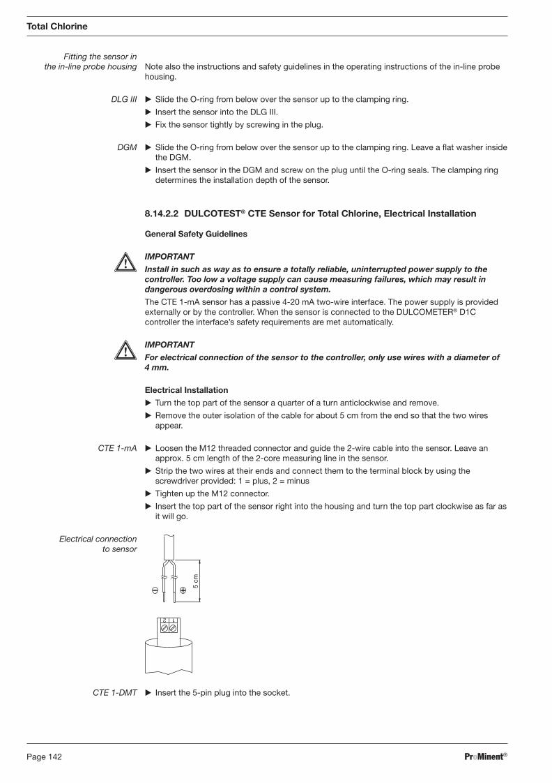
ProMinent®Page 142
Total Chlorine
Fitting the sensor in the in-line probe housing Note also the instructions and safety guidelines in the operating instructions of the in-line probe
housing.
DLG III � Slide the O-ring from below over the sensor up to the clamping ring.
� Insert the sensor into the DLG III.
� Fix the sensor tightly by screwing in the plug.
DGM � Slide the O-ring from below over the sensor up to the clamping ring. Leave a fl at washer inside the DGM.
� Insert the sensor in the DGM and screw on the plug until the O-ring seals. The clamping ring determines the installation depth of the sensor.
8.14.2.2 DULCOTEST® CTE Sensor for Total Chlorine, Electrical Installation
General Safety Guidelines
IMPORTANT
Install in such as way as to ensure a totally reliable, uninterrupted power supply to the controller. Too low a voltage supply can cause measuring failures, which may result in dangerous overdosing within a control system.
The CTE 1-mA sensor has a passive 4-20 mA two-wire interface. The power supply is provided externally or by the controller. When the sensor is connected to the DULCOMETER® D1C controller the interface’s safety require ments are met automatically.
IMPORTANT
For electrical connection of the sensor to the controller, only use wires with a diameter of 4 mm.
Electrical Installation
� Turn the top part of the sensor a quarter of a turn anticlockwise and remove.
� Remove the outer isolation of the cable for about 5 cm from the end so that the two wires appear.
CTE 1-mA � Loosen the M12 threaded connector and guide the 2-wire cable into the sensor. Leave an approx. 5 cm length of the 2-core measuring line in the sensor.
� Strip the two wires at their ends and connect them to the terminal block by using the screwdriver provided: 1 = plus, 2 = minus
� Tighten up the M12 connector.
� Insert the top part of the sensor right into the housing and turn the top part clockwise as far as it will go.
Electrical connection to sensor
1 2
5 cm
CTE 1-DMT � Insert the 5-pin plug into the socket.
BA_DR_001_02_09_GB.indd 142BA_DR_001_02_09_GB.indd 142 24.02.2009 12:24:10 Uhr24.02.2009 12:24:10 Uhr
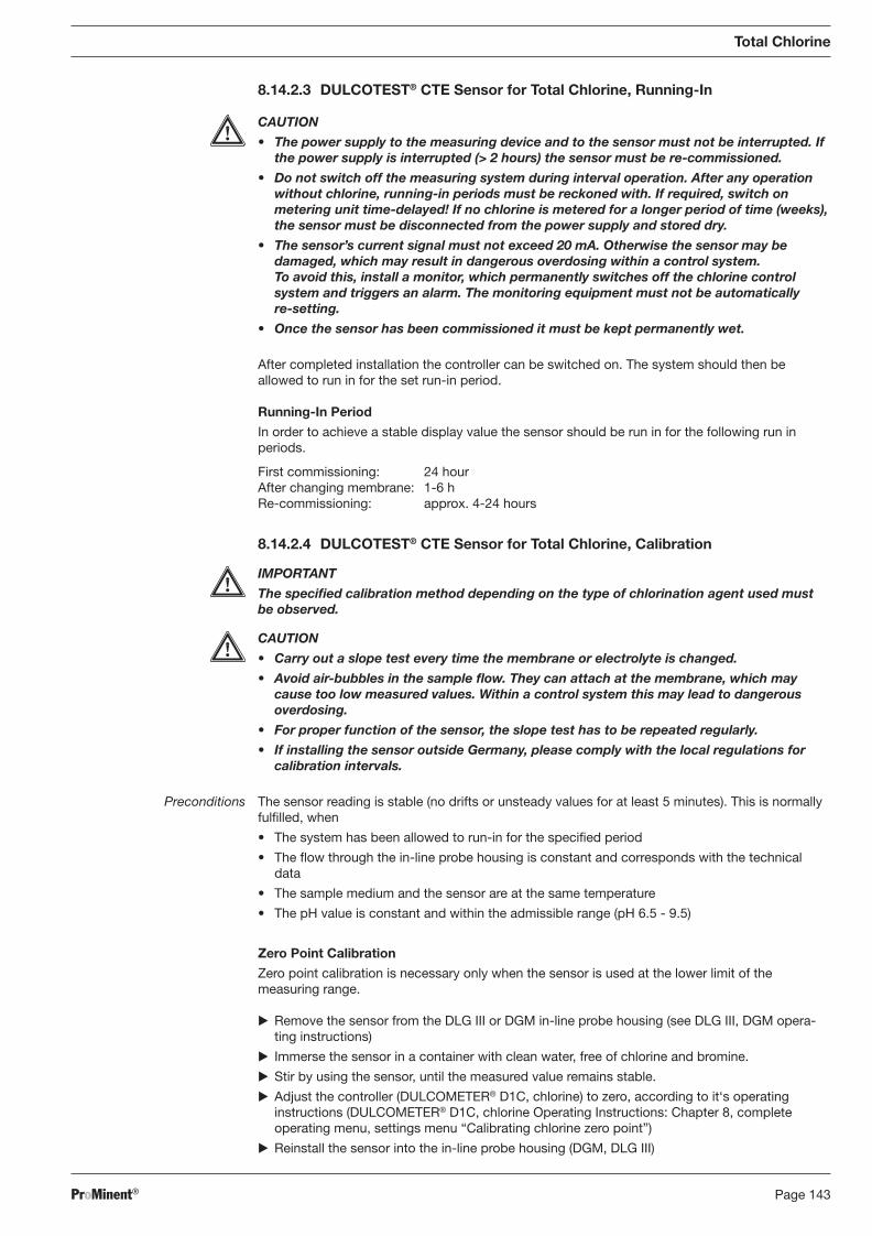
ProMinent® Page 143
8.14.2.3 DULCOTEST® CTE Sensor for Total Chlorine, Running-In
CAUTION
• The power supply to the measuring device and to the sensor must not be interrupted. If the power supply is interrupted (> 2 hours) the sensor must be re-commis sioned.
• Do not switch off the measuring system during interval operation. After any operation without chlorine, running-in periods must be reckoned with. If required, switch on metering unit time-delayed! If no chlorine is metered for a longer period of time (weeks), the sensor must be disconnected from the power supply and stored dry.
• The sensor’s current signal must not exceed 20 mA. Otherwise the sensor may be damaged, which may result in dangerous overdosing within a control system. To avoid this, install a monitor, which permanently switches off the chlorine control system and triggers an alarm. The monitoring equipment must not be automatically re-setting.
• Once the sensor has been commissioned it must be kept permanently wet.
After completed installation the controller can be switched on. The system should then be allowed to run in for the set run-in period.
Running-In Period
In order to achieve a stable display value the sensor should be run in for the following run in periods.
First commissioning: 24 hour After changing membrane: 1-6 h Re-commissioning: approx. 4-24 hours
8.14.2.4 DULCOTEST® CTE Sensor for Total Chlorine, Calibration
IMPORTANT
The specifi ed calibration method depending on the type of chlorination agent used must be observed.
CAUTION
• Carry out a slope test every time the membrane or electrolyte is changed.
• Avoid air-bubbles in the sample fl ow. They can attach at the membrane, which may cause too low measured values. Within a control system this may lead to dangerous over dosing.
• For proper function of the sensor, the slope test has to be repeated regularly.
• If installing the sensor outside Germany, please comply with the local regulations for calibration intervals.
Preconditions The sensor reading is stable (no drifts or unsteady values for at least 5 minutes). This is normally fulfi lled, when
• The system has been allowed to run-in for the specifi ed period
• The fl ow through the in-line probe housing is constant and corresponds with the technical data
• The sample medium and the sensor are at the same temperature
• The pH value is constant and within the admissible range (pH 6.5 - 9.5)
Zero Point Calibration
Zero point calibration is necessary only when the sensor is used at the lower limit of the meas ur ing range.
� Remove the sensor from the DLG III or DGM in-line probe housing (see DLG III, DGM opera-ting instructions)
� Immerse the sensor in a container with clean water, free of chlorine and bromine.
� Stir by using the sensor, until the measured value remains stable.
� Adjust the controller (DULCOMETER® D1C, chlorine) to zero, according to it‘s operating instructions (DULCOMETER® D1C, chlorine Operating Instructions: Chapter 8, complete operating menu, settings menu “Calibrating chlorine zero point”)
� Reinstall the sensor into the in-line probe housing (DGM, DLG III)
Total Chlorine
BA_DR_001_02_09_GB.indd 143BA_DR_001_02_09_GB.indd 143 24.02.2009 12:24:10 Uhr24.02.2009 12:24:10 Uhr
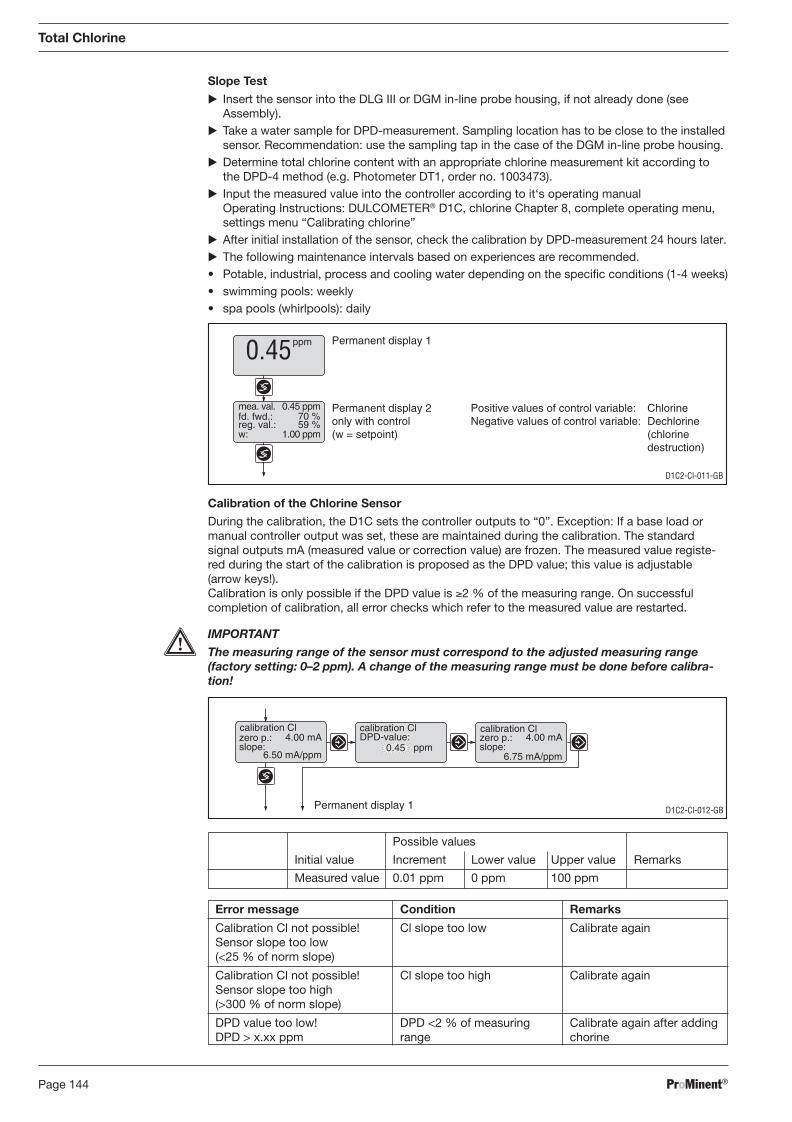
ProMinent®Page 144
Total Chlorine
Slope Test
� Insert the sensor into the DLG III or DGM in-line probe housing, if not already done (see Assembly).
� Take a water sample for DPD-measurement. Sampling location has to be close to the installed sensor. Recommendation: use the sampling tap in the case of the DGM in-line probe housing.
� Determine total chlorine content with an appropriate chlorine measurement kit according to the DPD-4 method (e.g. Photometer DT1, order no. 1003473).
� Input the measured value into the controller according to it‘s operating manual Operating Instructions: DULCOMETER® D1C, chlorine Chapter 8, complete operating menu, settings menu “Calibrating chlorine”
� After initial installation of the sensor, check the calibration by DPD-measurement 24 hours later. � The following maintenance intervals based on experiences are recommended. • Potable, industrial, process and cooling water depending on the specifi c conditions (1-4 weeks) • swimming pools: weekly • spa pools (whirlpools): daily
Calibration of the Chlorine Sensor
During the calibration, the D1C sets the controller outputs to “0”. Exception: If a base load or manual controller output was set, these are maintained during the calibration. The standard signal outputs mA (measured value or correction value) are frozen. The measured value registe-red during the start of the calibration is proposed as the DPD value; this value is adjustable (arrow keys!).
Calibration is only possible if the DPD value is ≥2 % of the measuring range. On successful completion of calibration, all error checks which refer to the measured value are restarted.
IMPORTANT
The measuring range of the sensor must correspond to the adjusted measuring range (factory setting: 0–2 ppm). A change of the measuring range must be done before cali bra-tion!
D1C2-Cl-011-GB
Permanent display 1
Permanent display 2only with control(w = setpoint)
ppm0.45
mea. val.fd. fwd.:reg. val.:
0.45 ppm
w: 1.00 ppm
70 %59 %
Positive values of control variable: ChlorineNegative values of control variable: Dechlorine
(chlorinedestruction)
D1C2-Cl-012-GB
calibration Cl calibration ClDPD-value:
0.45 ppmzero p.:slope:
4.00 mA
6.50 mA/ppm
calibration Clzero p.:slope:
4.00 mA
6.75 mA/ppm
Permanent display 1
Possible values
Initial value Increment Lower value Upper value Remarks
Measured value 0.01 ppm 0 ppm 100 ppm
Error message Condition Remarks
Calibration Cl not possible! Cl slope too low Calibrate again Sensor slope too low (<25 % of norm slope)
Calibration Cl not possible! Cl slope too high Calibrate again Sensor slope too high (>300 % of norm slope)
DPD value too low! DPD <2 % of measuring Calibrate again after adding DPD > x.xx ppm range chorine
BA_DR_001_02_09_GB.indd 144BA_DR_001_02_09_GB.indd 144 24.02.2009 12:24:10 Uhr24.02.2009 12:24:10 Uhr
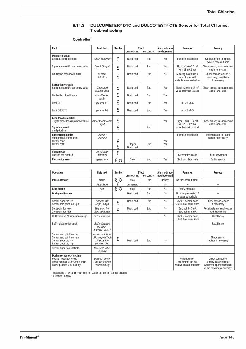
ProMinent® Page 145
Operation Note text Symbol Effect Alarm with ack- Remarks Remedy on metering on control nowledgement
Pause contact Pause Stop Stop No/Yes* No further fault check –
Pause/Hold Unchanged ** No – –
Stop button Stop Stop Stop No Relay drops out –
During calibration Basic load Stop No No error processing of – measured variable
Sensor slope too low Slope Cl low Basic load Stop No 25 % > sensor slope Check sensor, replace Sensor zero point too high Slope Cl high > 200 % of norm slope if necessary
Zero point too low Zero point low Basic load Stop No Zero point <3 mA Recalibrate in sample water Zero point too high Zero point high Zero point >5 mA without chlorine
DPD-value <2 % measuring range DPD > x.xx ppm No 25 % > sensor slope Recalibrate > 200 % of norm slope
Buffer distance too small Buffer distance Recalibrate too small ! Δ buffer >2 pH !
Sensor zero point too low pH zero point low Sensor zero point too high pH zero point high Check sensor, Sensor slope too low pH slope low Basic load Stop No replace if necessary Sensor slope too high pH slope high
Sensor signal too unstable Measured value unstable
During servomotor setting Position feedback wrong Direction check Without correct Check connection Upper position <40 % max. value Final value small adjustment the last of relay, potentiometer Lower position >30 % range Final value big valid values are still used Adjust the operation region of the servomotor correctly
* depending on whether “Alarm on” or “Alarm off” set in “General settings” ** Function PI stable
8.14.3 DULCOMETER® D1C and DULCOTEST® CTE Sensor for Total Chlorine, Troubleshooting
Controller
Fault Fault text Symbol Effect Alarm with ack- Remarks Remedy on metering on control nowledgement
Measured value Checkout time exceeded Check Cl sensor Basic load Stop Yes Function detachable Check function of sensor, exceed checkout time
Signal exceeded/drops below value Check Cl input Basic load Stop Yes Signal <3.0 ±0.2 mA Check sensor, transducer and or >23 ±0.2 mA cable connection
Calibration sensor with error Cl calib. Basic load Stop No Metering continues in Check sensor, replace if defective case of error with necessary, recalibrate unstable measured values if necessary
Correction variable Signal exceeded/drops below value Check feed Basic load Stop Yes Signal <3.0 or >23 mA Check sensor, transducer and forward input Value last valid is used cable connection
Calibration pH with error pH calibration Basic load Stop Yes faulty
Limit CLE pH limit 1/2 Basic load Stop Yes pH <5 >8.5
Limit CGE/CTE pH limit 1/2 Basic load Stop Yes pH <5 >9.5
Feed forward control Signal exceeded/drops below value Check feed forward Yes Signal <3.0 ±0.2 mA Check sensor, transducer and input or >23 ±0.2 mA cable connection Signal exceeded, Stop Value last valid is used multiplicative
Limit transgression Cl limit 1 Function detachable Determine cause, reset after checkout time limits Cl limit 2 values if necessary Control “on” Yes Control “off” Stop or Stop Yes Basic load
Servomotor Servomotor Position not reached defective Servomotor closes Check servomotor
Electronics error System error Stop Stop Yes Electronic data faulty Call in service
Total Chlorine
BA_DR_001_02_09_GB.indd 145BA_DR_001_02_09_GB.indd 145 24.02.2009 12:24:10 Uhr24.02.2009 12:24:10 Uhr
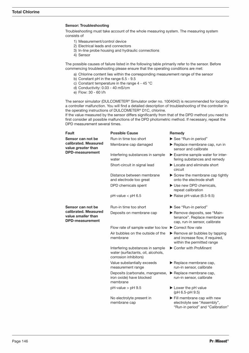
ProMinent®Page 146
Total Chlorine
Sensor: Troubleshooting
Troubleshooting must take account of the whole measuring system. The measuring system consists of
1) Measurement/control device 2) Electrical leads and connectors 3) In-line probe housing and hydraulic connections 4) Sensor
The possible causes of failure listed in the following table primarily refer to the sensor. Before commencing troubleshooting please ensure that the operating conditions are met:
a) Chlorine content lies within the corresponding measurement range of the sensor b) Constant pH in the range 6.5 - 9.5 c) Constant temperature in the range 4 - 45 °C d) Conductivity: 0.03 - 40 mS/cm e) Flow: 30 - 60 l/h
The sensor simulator (DULCOMETER® Simulator order no. 1004042) is recommended for locating a controller malfunction. You will fi nd a detailed description of troubleshooting of the controller in the operating instructions of DULCOMETER® D1C, chlorine.
If the value measured by the sensor differs signifi cantly from that of the DPD method you need to fi rst consider all possible malfunctions of the DPD photometric method. If necessary, repeat the DPD measurement several times.
Fault
Sensor can not be calibrated. Measured value greater than DPD-measurement
Sensor can not be calibrated. Measured value smaller than DPD-measurement
Possible Cause
Run-in time too short
Membrane cap damaged
Interfering substances in sample water
Short-circuit in signal lead
Distance between membrane and electrode too great
DPD chemicals spent
pH-value < pH 6.5
Run-in time too short
Deposits on membrane cap
Flow rate of sample water too low
Air bubbles on the outside of the membrane
Interfering substances in sample water (surfactants, oil, alcohols, corrosion inhibitors)
Value substantially exceeds measurement range
Deposits (carbonate, manganese, iron oxide) have blocked membrane
pH-value > pH 9.5
No electrolyte present in membrane cap
Remedy
� See “Run-in period”
� Replace membrane cap, run in sensor and calibrate
� Examine sample water for in ter-fer ing substances and remedy
� Locate and eliminate short circuit
� Screw the membrane cap tightly onto the electrode shaft
� Use new DPD chemicals, repeat calibration
� Raise pH-value (6.5-9.5)
� See “Run-in period”
� Remove deposits, see “Main-tenance”. Replace membrane cap, run-in sensor, calibrate
� Correct fl ow rate
� Remove air bubbles by tapping and increase fl ow, if required, within the permitted range
� Confer with ProMinent
� Replace membrane cap, run-in sensor, calibrate
� Replace membrane cap, run-in sensor, calibrate
� Lower the pH value (pH 6.5-pH 9.5)
� Fill membrane cap with new electrolyte see “Assembly”, “Run-in period” and “Cali bra tion”
BA_DR_001_02_09_GB.indd 146BA_DR_001_02_09_GB.indd 146 24.02.2009 12:24:10 Uhr24.02.2009 12:24:10 Uhr
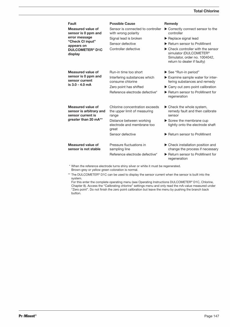
ProMinent® Page 147
Total Chlorine
Fault Possible Cause Remedy
* When the reference electrode turns shiny silver or white it must be regenerated. Brown-grey or yellow green coloration is normal.
** The DULCOMETER® D1C can be used to display the sensor current when the sensor is built into the system. For this enter the complete operating menu (see Operating Instructions DULCOMETER® D1C, Chlorine, Chapter 8). Access the “Calibrating chlorine” settings menu and only read the mA-value measured under “Zero point”. Do not fi nish the zero point calibration but leave the menu by pushing the branch back button.
Measured value of sensor is 0 ppm and error message “Check Cl input” appears on DULCOMETER® D1C display
Measured value of sensor is 0 ppm and sensor current is 3.0 - 4.0 mA
Measured value of sensor is arbitrary and sensor current is greater than 20 mA**
Measured value of sensor is not stable
Sensor is connected to controller with wrong polarity
Signal lead is broken
Sensor defective
Controller defective
Run-in time too short
Interfering substances which consume chlorine
Zero point has shifted
Reference electrode defective*
Chlorine concentration exceeds the upper limit of measuring range
Distance between working electrode and membrane too great
Sensor defective
Pressure fl uctuations in sampling line
Reference electrode defective*
� Correctly connect sensor to the controller
� Replace signal lead
� Return sensor to ProMinent
� Check controller with the sensor simulator (DULCOMETER® Simulator, order no. 1004042, return to dealer if faulty)
� See “Run-in period”
� Examine sample water for inter-fering substances and remedy
� Carry out zero point calibration
� Return sensor to ProMinent for regeneration
� Check the whole system, remedy fault and then calibrate sensor
� Screw the membrane cup tightly onto the electrode shaft
� Return sensor to ProMinent
� Check installation position and change the process if necessary
� Return sensor to ProMinent for regeneration
BA_DR_001_02_09_GB.indd 147BA_DR_001_02_09_GB.indd 147 24.02.2009 12:24:10 Uhr24.02.2009 12:24:10 Uhr
ProMinent®Page 148
8.14.4 DULCOMETER® D1C Measured Variable Chlorine and DULCOTEST® CTE Sensor for Total Chlorine, Maintenance
Controller
The DULCOMETER® controller type D1C for the measured variable total chlorine is maintenance-free.
Sensor
IMPORTANT
• Service the sensor regularly to avoid overdosing within a control system, due to in cor rect measured value.
• Observe the current national regulations for maintenance intervals.
• Do not touch the electrodes or allow them to come into contact with greasy substances.
• Never attempt to clean the membrane with acid/alkaline solutions, cleaning reagents or mechanical aids (brushes or similar).
Maintenance interval based on experience are:
• Potable, industrial, process and cooling water: depending on the specifi c conditions (1-4 weeks)
• swimming pools: weekly
• spa pools (whirlpools): daily
Maintenance Work
� Check the sensor regularly for dirt, algae and air bubbles. As far as possible, avoid contamina-tion of the membrane with solid particles, deposits etc. Eliminate air bubbles by increasing the fl ow rate.
� Check the displayed sensor value on the controller regularly according to the DPD-4 method using an appropriate chlorine measurement kit.
� If necessary, recalibrate the sensor.
� If calibration cannot be carried out properly, the membrane cap must be replaced and cali bra-tion must be repeated.
Total Chlorine
BA_DR_001_02_09_GB.indd 148BA_DR_001_02_09_GB.indd 148 24.02.2009 12:24:10 Uhr24.02.2009 12:24:10 Uhr
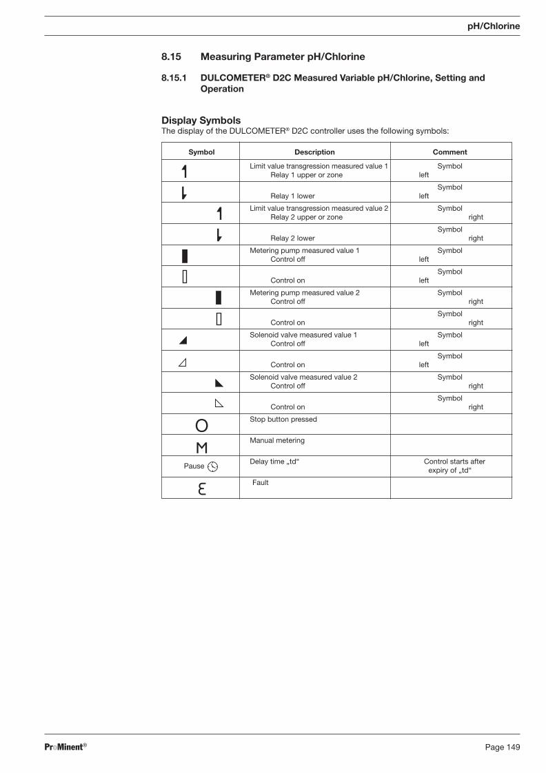
ProMinent® Page 149
8.15 Measuring Parameter pH/Chlorine
8.15.1 DULCOMETER® D2C Measured Variable pH/Chlorine, Setting and Operation
Display Symbols The display of the DULCOMETER® D2C controller uses the following symbols:
pH/Chlorine
Symbol Description Comment
Limit value transgression measured value 1 Symbol Relay 1 upper or zone left
Symbol Relay 1 lower left
Limit value transgression measured value 2 Symbol Relay 2 upper or zone right
Symbol Relay 2 lower right
Metering pump measured value 1 Symbol Control off left
Symbol Control on left
Metering pump measured value 2 Symbol Control off right
Symbol Control on right
Solenoid valve measured value 1 Symbol Control off left
Symbol Control on left
Solenoid valve measured value 2 Symbol Control off right
Symbol Control on right
Stop button pressed
Manual metering
Pause
Delay time „td“ Control starts after expiry of „td“
Fault
BA_DR_001_02_09_GB.indd 149BA_DR_001_02_09_GB.indd 149 24.02.2009 12:24:10 Uhr24.02.2009 12:24:10 Uhr
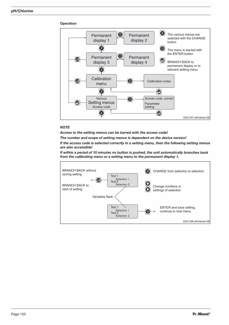
ProMinent®Page 150
pH/Chlorine
Operation
NOTE
Access to the setting menus can be barred with the access code!
The number and scope of setting menus is dependent on the device version!
If the access code is selected correctly in a setting menu, then the following setting menus are also accessible!
If within a period of 10 minutes no button is pushed, the unit automatically branches back from the calibrating menu or a setting menu to the permanent display 1.
Access code, correct
Parametersetting
Calibration notes
Permanentdisplay 1
Permanentdisplay 4
Calibrationmenu
Various
Access codeSetting menus
The various menus areselected with the CHANGEbutton
The menu is started withthe ENTER button
BRANCH BACK topermanent display or torelevant setting menu
Permanentdisplay 2
Permanentdisplay 3
D2C2-007-pH/chlorine GB
Selection 1
Selection 2
CHANGE from selection to selection
Change numbers orsettings of selection
Variables flash
ENTER and save setting,continue to next menu
BRANCH BACK withoutsaving setting
BRANCH BACK tostart of setting
Text 1
Text 2
Text 1
Text 2
Selection 1
Selection 2
D2C2-008-pH/chlorine-GB
BA_DR_001_02_09_GB.indd 150BA_DR_001_02_09_GB.indd 150 24.02.2009 12:24:10 Uhr24.02.2009 12:24:10 Uhr
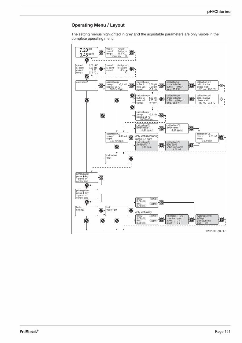
ProMinent® Page 151
Operating Menu / Layout
The setting menus highlighted in grey and the adjustable parameters are only visible in the complete operating menu.
pH/Chlorine
priming acidpress -key* pump oncontrol stop !
limit 2 lower 6.50 pHlimit 1 upper 8.00 pH
7.200.45
pH
ppm
value 1 7.20 pHvalue 2 0.45 ppmtemp.: 23.5 °C
stop-key
value 2 0.45 ppms. point 0.45 ppmctrlout 0 %
value 1 7.00 pHs. point 7.20 pHctrlout 0 %temp.: 23.5 °C
calibration pHzero p.: -3,1 mVslope at 25 °C
58.32 mV/pH
calibration? calibration pHbuffer 1: 7.00 pHmea. val: 7.00 pHsignal: -3,1 mV
calibration pHcalib. 1 activeplease wait!
-3.1 mV 23.5 °C
calibration pHbuffer 2: 4.00 pHmea. val: 4.00 pHsignal: 157 mV
calibration pHcalib. 2 activeplease wait!
157 mV 23.5 °C
calibrationend?
limitvalue 1 pH
limitssetting?
calibration Cl2zero p.: 4.00 mAslope:
6.00 mA/ppm
only with relay
calibration pHprobe in bufferbuffer: 7.00 pHtemp.: 23.5 °C
calibration pHprobe in bufferbuffer: 4.00 pHtemp.: 23.5 °C
only with measuringrange 0,5 ppm
limit relay LV2- active closedΔt on 0 sΔt off 0 s
hysteresis limit: 0.20 pHcheckout timelimit: off
limit 2 lower 8.00 pHlimit 1 upper 6.50 pH
priming chlorpress -key* pump oncontrol stop !
calibration Cl2zero p.: 4.00 mAslope:
6 mA/ppm
calibration pHzero p.: -3,1 mVslope at 25 °C
53.70 mV/pH
calibration Cl2zero point:
0.45 ppm
calibration Cl2zero pointvalue take over?
4.01 mA
calibration Cl2 DPD-value
0.45 ppm
calibration Cl2 DPD-value:
0.45 ppm
D2C2-001-pH-Cl-D
BA_DR_001_02_09_GB.indd 151BA_DR_001_02_09_GB.indd 151 24.02.2009 12:24:10 Uhr24.02.2009 12:24:10 Uhr
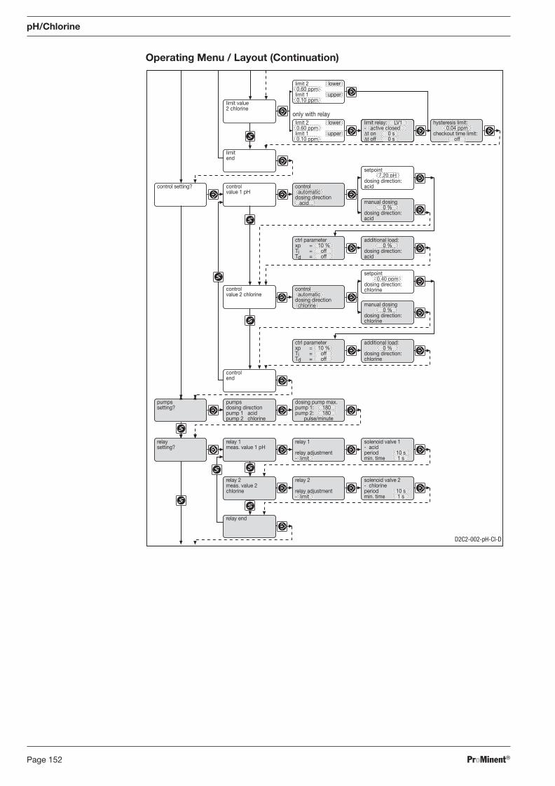
ProMinent®Page 152
pH/Chlorine
Operating Menu / Layout (Continuation)
relaysetting?
relay 1meas. value 1 pH
relay 2meas. value 2chlorine
relay end
solenoid valve 2- chlorineperiod 10 smin. time 1 s
solenoid valve 1- acidperiod 10 smin. time 1 s
relay 1
relay adjustment- limit
relay 2
relay adjustment- limit
pumpssetting?
pumpsdosing directionpump 1 acidpump 2 chlorine
dosing pump max.pump 1: 180pump 2: 180
pulse/minute
setpoint0.40 ppm
dosing direction:chlorine
setpoint7.20 pH
dosing direction:acid
controlvalue 2 chlorine
controlend
control setting? controlvalue 1 pH
control automaticdosing direction acid manual dosing
0 %dosing direction:acid
ctrl parameterxp = 10 %Ti = offTd = off
ctrl parameterxp = 10 %Ti = offTd = off
additional load:0 %
dosing direction:acid
control automaticdosing direction chlorine manual dosing
0 %dosing direction:chlorine
additional load:0 %
dosing direction:chlorine
limitend
only with relayhysteresis limit:
0.04 ppmcheckout time limit:
off
limit value2 chlorine
limit relay: LV1- active closedΔt on 0 sΔt off 0 s
limit 2 lower 0.60 ppmlimit 1 upper 0.10 ppm
limit 2 lower 0.60 ppmlimit 1 upper 0.10 ppm
D2C2-002-pH-Cl-D
BA_DR_001_02_09_GB.indd 152BA_DR_001_02_09_GB.indd 152 24.02.2009 12:24:10 Uhr24.02.2009 12:24:10 Uhr
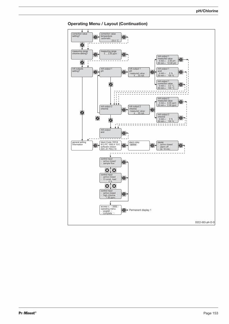
ProMinent® Page 153
Operating Menu / Layout (Continuation)
pH/Chlorine
correction valuesetting?
measuring rangechlorine setting?
measuring range0 ... 2.00 ppm
mA output 1pH
mA outputssetting?
mA output 1measured value 4 mA = 2.00 pH20 mA = 12.00 pH
mA output 1acid 4 mA = 0 %20 mA = 100 %
mA output 1pH measured value
4 ... 20 mA
mA output 1correction value 4 mA = 0.0 °C20 mA = 100 °C
mA output 2chlorine
mA outputend
mA output 2chlorine measured value
4 ... 20 mA
mA output 2measured value 4 mA = 0.00 ppm20 mA = 2.00 ppm
mA output 2chlorine 4 mA = 0 %20 mA = 100 %
Ident-Code: D2CAW 0 PC 1000 A 10 Esoftware versionD2C-A1 FW.2.10
general settinginformation
alarm relay active
pause- active closed- alarm off- td: 10 min.
correction valuetemperature automatic
23.5 °C
Permanent display 1
control input- active closed- sample flow
control input- active closed- Cl const. load
0 %
control input- active closed- high chlorine
1.50 ppm
access c.: 5000operating menu:- english- complete
D2C2-003-pH-Cl-D
BA_DR_001_02_09_GB.indd 153BA_DR_001_02_09_GB.indd 153 24.02.2009 12:24:11 Uhr24.02.2009 12:24:11 Uhr
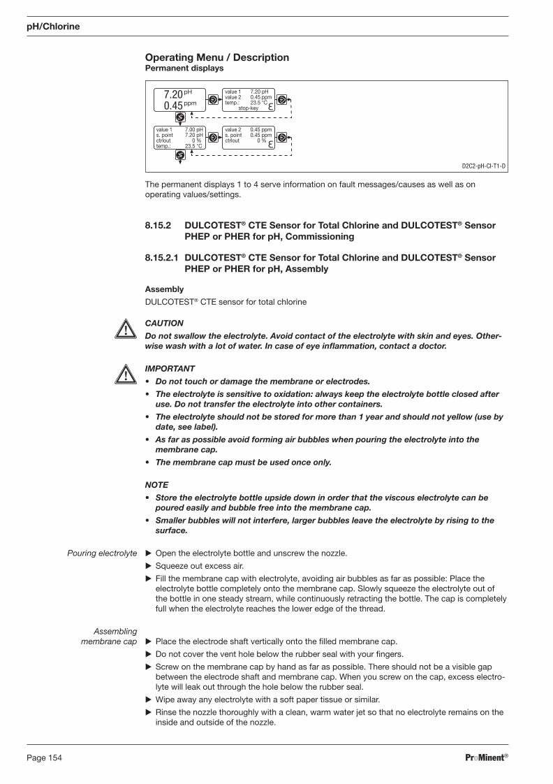
ProMinent®Page 154
Operating Menu / Description Permanent displays
pH/Chlorine
The permanent displays 1 to 4 serve information on fault messages/causes as well as on operating values/settings.
8.15.2 DULCOTEST® CTE Sensor for Total Chlorine and DULCOTEST® Sensor PHEP or PHER for pH, Commissioning
8.15.2.1 DULCOTEST® CTE Sensor for Total Chlorine and DULCOTEST® Sensor PHEP or PHER for pH, Assembly
Assembly
DULCOTEST® CTE sensor for total chlorine
CAUTION
Do not swallow the electrolyte. Avoid contact of the electrolyte with skin and eyes. Other-wise wash with a lot of water. In case of eye infl ammation, contact a doctor.
IMPORTANT
• Do not touch or damage the membrane or electrodes.
• The electrolyte is sensitive to oxidation: always keep the electrolyte bottle closed after use. Do not transfer the electrolyte into other containers.
• The electrolyte should not be stored for more than 1 year and should not yellow (use by date, see label).
• As far as possible avoid forming air bubbles when pouring the electrolyte into the membrane cap.
• The membrane cap must be used once only.
NOTE
• Store the electrolyte bottle upside down in order that the viscous electrolyte can be poured easily and bubble free into the membrane cap.
• Smaller bubbles will not interfere, larger bubbles leave the electrolyte by rising to the surface.
Pouring electrolyte � Open the electrolyte bottle and unscrew the nozzle.
� Squeeze out excess air.
� Fill the membrane cap with electrolyte, avoiding air bubbles as far as possible: Place the electrolyte bottle completely onto the membrane cap. Slowly squeeze the electrolyte out of the bottle in one steady stream, while continuously retracting the bottle. The cap is completely full when the electrolyte reaches the lower edge of the thread.
Assembling membrane cap � Place the electrode shaft vertically onto the fi lled membrane cap.
� Do not cover the vent hole below the rubber seal with your fi ngers.
� Screw on the membrane cap by hand as far as possible. There should not be a visible gap between the electrode shaft and membrane cap. When you screw on the cap, excess elec tro-lyte will leak out through the hole below the rubber seal.
� Wipe away any electrolyte with a soft paper tissue or similar.
� Rinse the nozzle thoroughly with a clean, warm water jet so that no electrolyte remains on the inside and outside of the nozzle.
7.200.45
pH
ppm
value 1 7.20 pHvalue 2 0.45 ppmtemp.: 23.5 °C
stop-key
value 2 0.45 ppms. point 0.45 ppmctrlout 0 %
value 1 7.00 pHs. point 7.20 pHctrlout 0 %temp.: 23.5 °C
D2C2-pH-CI-T1-D
BA_DR_001_02_09_GB.indd 154BA_DR_001_02_09_GB.indd 154 24.02.2009 12:24:11 Uhr24.02.2009 12:24:11 Uhr
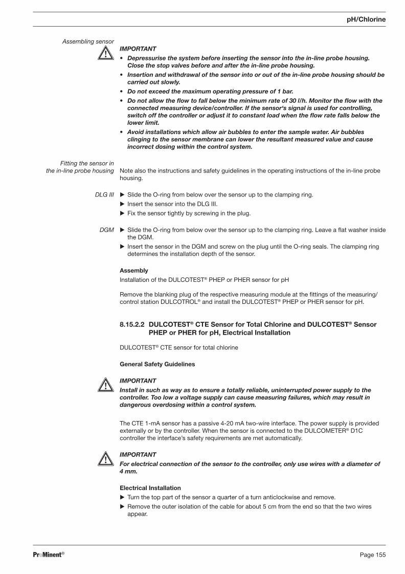
ProMinent® Page 155
pH/Chlorine
Assembling sensor IMPORTANT
• Depressurise the system before inserting the sensor into the in-line probe housing. Close the stop valves before and after the in-line probe housing.
• Insertion and withdrawal of the sensor into or out of the in-line probe housing should be carried out slowly.
• Do not exceed the maximum operating pressure of 1 bar.
• Do not allow the fl ow to fall below the minimum rate of 30 l/h. Monitor the fl ow with the connected measuring device/controller. If the sensor‘s signal is used for con trolling, switch off the controller or adjust it to constant load when the fl ow rate falls below the lower limit.
• Avoid installations which allow air bubbles to enter the sample water. Air bubbles clinging to the sensor membrane can lower the resultant measured value and cause incorrect dosing within the control system.
Fitting the sensor in the in-line probe housing Note also the instructions and safety guidelines in the operating instructions of the in-line probe
housing.
DLG III � Slide the O-ring from below over the sensor up to the clamping ring.
� Insert the sensor into the DLG III.
� Fix the sensor tightly by screwing in the plug.
DGM � Slide the O-ring from below over the sensor up to the clamping ring. Leave a fl at washer inside the DGM.
� Insert the sensor in the DGM and screw on the plug until the O-ring seals. The clamping ring determines the installation depth of the sensor.
Assembly
Installation of the DULCOTEST® PHEP or PHER sensor for pH
Remove the blanking plug of the respective measuring module at the fi ttings of the measuring/control station DULCOTROL® and install the DULCOTEST® PHEP or PHER sensor for pH.
8.15.2.2 DULCOTEST® CTE Sensor for Total Chlorine and DULCOTEST® Sensor PHEP or PHER for pH, Electrical Installation
DULCOTEST® CTE sensor for total chlorine
General Safety Guidelines
IMPORTANT
Install in such as way as to ensure a totally reliable, uninterrupted power supply to the controller. Too low a voltage supply can cause measuring failures, which may result in dangerous overdosing within a control system.
The CTE 1-mA sensor has a passive 4-20 mA two-wire interface. The power supply is provided externally or by the controller. When the sensor is connected to the DULCOMETER® D1C controller the interface’s safety require ments are met automatically.
IMPORTANT
For electrical connection of the sensor to the controller, only use wires with a diameter of 4 mm.
Electrical Installation
� Turn the top part of the sensor a quarter of a turn anticlockwise and remove.
� Remove the outer isolation of the cable for about 5 cm from the end so that the two wires appear.
BA_DR_001_02_09_GB.indd 155BA_DR_001_02_09_GB.indd 155 24.02.2009 12:24:11 Uhr24.02.2009 12:24:11 Uhr
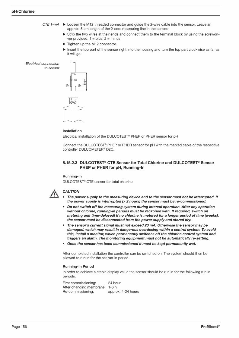
ProMinent®Page 156
CTE 1-mA � Loosen the M12 threaded connector and guide the 2-wire cable into the sensor. Leave an approx. 5 cm length of the 2-core measuring line in the sensor.
� Strip the two wires at their ends and connect them to the terminal block by using the screwdri-ver provided: 1 = plus, 2 = minus
� Tighten up the M12 connector.
� Insert the top part of the sensor right into the housing and turn the top part clockwise as far as it will go.
Electrical connection to sensor
1 2
5 cm
Installation
Electrical installation of the DULCOTEST® PHEP or PHER sensor for pH
Connect the DULCOTEST® PHEP or PHER sensor for pH with the marked cable of the respective controller DULCOMETER® D2C.
8.15.2.3 DULCOTEST® CTE Sensor for Total Chlorine and DULCOTEST® Sensor PHEP or PHER for pH, Running-In
Running-In
DULCOTEST® CTE sensor for total chlorine
CAUTION
• The power supply to the measuring device and to the sensor must not be interrupted. If the power supply is interrupted (> 2 hours) the sensor must be re-commis sioned.
• Do not switch off the measuring system during interval operation. After any operation without chlorine, running-in periods must be reckoned with. If required, switch on metering unit time-delayed! If no chlorine is metered for a longer period of time (weeks), the sensor must be disconnected from the power supply and stored dry.
• The sensor’s current signal must not exceed 20 mA. Otherwise the sensor may be damaged, which may result in dangerous overdosing within a control system. To avoid this, install a monitor, which permanently switches off the chlorine control system and triggers an alarm. The monitoring equipment must not be automatically re-setting.
• Once the sensor has been commissioned it must be kept permanently wet.
After completed installation the controller can be switched on. The system should then be allowed to run in for the set run-in period.
Running-In Period
In order to achieve a stable display value the sensor should be run in for the following run in periods.
First commissioning: 24 hour After changing membrane: 1-6 h Re-commissioning: approx. 4-24 hours
pH/Chlorine
BA_DR_001_02_09_GB.indd 156BA_DR_001_02_09_GB.indd 156 24.02.2009 12:24:11 Uhr24.02.2009 12:24:11 Uhr
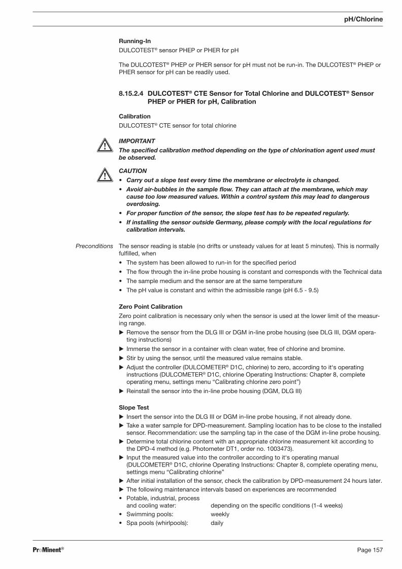
ProMinent® Page 157
pH/Chlorine
Running-In
DULCOTEST® sensor PHEP or PHER for pH
The DULCOTEST® PHEP or PHER sensor for pH must not be run-in. The DULCOTEST® PHEP or PHER sensor for pH can be readily used.
8.15.2.4 DULCOTEST® CTE Sensor for Total Chlorine and DULCOTEST® Sensor PHEP or PHER for pH, Calibration
Calibration
DULCOTEST® CTE sensor for total chlorine
IMPORTANT
The specifi ed calibration method depending on the type of chlorination agent used must be observed.
CAUTION
• Carry out a slope test every time the membrane or electrolyte is changed.
• Avoid air-bubbles in the sample fl ow. They can attach at the membrane, which may cause too low measured values. Within a control system this may lead to dangerous over dosing.
• For proper function of the sensor, the slope test has to be repeated regularly.
• If installing the sensor outside Germany, please comply with the local regulations for calibration intervals.
Preconditions The sensor reading is stable (no drifts or unsteady values for at least 5 minutes). This is normally fulfi lled, when
• The system has been allowed to run-in for the specifi ed period
• The fl ow through the in-line probe housing is constant and corresponds with the Technical data
• The sample medium and the sensor are at the same temperature
• The pH value is constant and within the admissible range (pH 6.5 - 9.5)
Zero Point Calibration
Zero point calibration is necessary only when the sensor is used at the lower limit of the meas ur-ing range.
� Remove the sensor from the DLG III or DGM in-line probe housing (see DLG III, DGM opera-ting instructions)
� Immerse the sensor in a container with clean water, free of chlorine and bromine.
� Stir by using the sensor, until the measured value remains stable.
� Adjust the controller (DULCOMETER® D1C, chlorine) to zero, according to it‘s operating instructions (DULCOMETER® D1C, chlorine Operating Instructions: Chapter 8, complete operating menu, settings menu “Calibrating chlorine zero point”)
� Reinstall the sensor into the in-line probe housing (DGM, DLG III)
Slope Test
� Insert the sensor into the DLG III or DGM in-line probe housing, if not already done. � Take a water sample for DPD-measurement. Sampling location has to be close to the installed
sensor. Recommendation: use the sampling tap in the case of the DGM in-line probe housing. � Determine total chlorine content with an appropriate chlorine measurement kit according to
the DPD-4 method (e.g. Photometer DT1, order no. 1003473). � Input the measured value into the controller according to it‘s operating manual
( DULCOMETER® D1C, chlorine Operating Instructions: Chapter 8, complete operating menu, settings menu “Calibrating chlorine”
� After initial installation of the sensor, check the calibration by DPD-measurement 24 hours later. � The following maintenance intervals based on experiences are recommended • Potable, industrial, process
and cooling water: depending on the specifi c conditions (1-4 weeks) • Swimming pools: weekly • Spa pools (whirlpools): daily
BA_DR_001_02_09_GB.indd 157BA_DR_001_02_09_GB.indd 157 24.02.2009 12:24:11 Uhr24.02.2009 12:24:11 Uhr
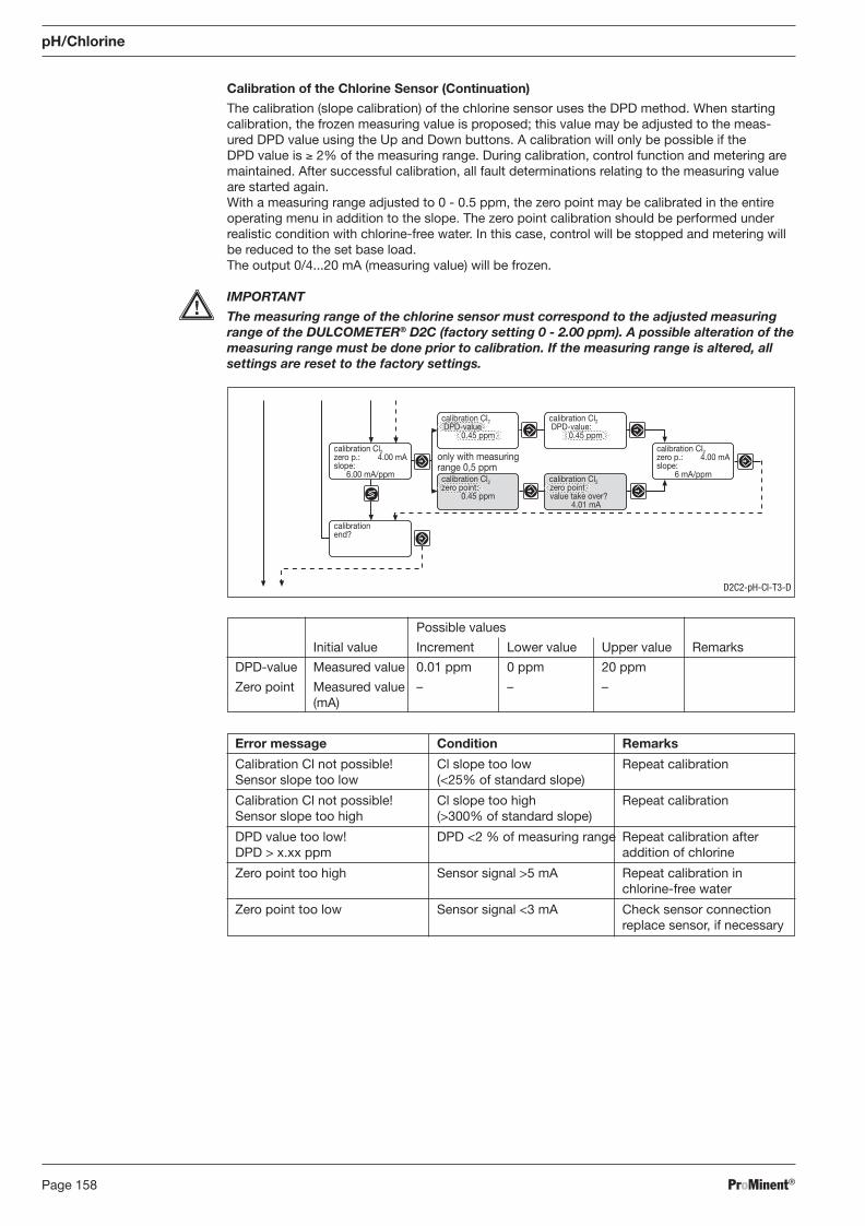
ProMinent®Page 158
Calibration of the Chlorine Sensor (Continuation)
The calibration (slope calibration) of the chlorine sensor uses the DPD method. When starting cali bra tion, the frozen measuring value is proposed; this value may be adjusted to the meas-ured DPD value using the Up and Down buttons. A calibration will only be possible if the DPD value is ≥ 2% of the measuring range. During calibration, control function and metering are maintained. After successful calibration, all fault determinations relating to the measuring value are started again. With a measuring range adjusted to 0 - 0.5 ppm, the zero point may be calibrated in the entire operating menu in addition to the slope. The zero point calibration should be performed under realistic condition with chlorine-free water. In this case, control will be stopped and metering will be reduced to the set base load. The output 0/4...20 mA (measuring value) will be frozen.
IMPORTANT
The measuring range of the chlorine sensor must correspond to the adjusted measuring range of the DULCOMETER® D2C (factory setting 0 - 2.00 ppm). A possible alteration of the measuring range must be done prior to calibration. If the measuring range is altered, all settings are reset to the factory settings.
pH/Chlorine
Possible values
Initial value Increment Lower value Upper value Remarks
DPD-value Measured value 0.01 ppm 0 ppm 20 ppm
Zero point Measured value – – – (mA)
Error message Condition Remarks
Calibration Cl not possible! Cl slope too low Repeat calibration Sensor slope too low (<25% of standard slope)
Calibration Cl not possible! Cl slope too high Repeat calibration Sensor slope too high (>300% of standard slope)
DPD value too low! DPD <2 % of measuring range Repeat calibration after DPD > x.xx ppm addition of chlorine
Zero point too high Sensor signal >5 mA Repeat calibration in chlorine-free water
Zero point too low Sensor signal <3 mA Check sensor connection replace sensor, if necessary
calibrationend?
calibration Cl2zero p.: 4.00 mAslope:
6.00 mA/ppm
only with measuringrange 0,5 ppm
calibration Cl2zero p.: 4.00 mAslope:
6 mA/ppmcalibration Cl2zero point:
0.45 ppm
calibration Cl2zero pointvalue take over?
4.01 mA
calibration Cl2 DPD-value
0.45 ppm
calibration Cl2 DPD-value:
0.45 ppm
D2C2-pH-CI-T3-D
BA_DR_001_02_09_GB.indd 158BA_DR_001_02_09_GB.indd 158 24.02.2009 12:24:11 Uhr24.02.2009 12:24:11 Uhr
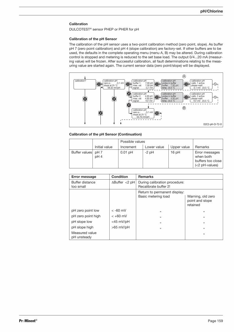
ProMinent® Page 159
pH/Chlorine
Calibration
DULCOTEST® sensor PHEP or PHER for pH
Calibration of the pH Sensor
The calibration of the pH sensor uses a two-point calibration method (zero point, slope). As buffer pH 7 (zero point calibration) and pH 4 (slope calibration) are factory-set. If other buffers are to be used, the defaults in the complete operating menu (menu A, B) may be altered. During calibration control is stopped and metering is reduced to the set base load. The output 0/4...20 mA (meas ur-ing value) will be frozen. After successful calibration, all fault determinations relating to the meas-ur ing value are started again. The current sensor data (zero point/slope) will be displayed.
Calibration of the pH Sensor (Continuation)
Possible values
Initial value Increment Lower value Upper value Remarks
Buffer values pH 7 0.01 pH -2 pH 16 pH Error messages pH 4 when both
buffers too close (<2 pH-values)
calibration pHzero p.: -3,1 mVslope at 25 °C
58.32 mV/pH
calibration? calibration pHbuffer 1: 7.00 pHmea. val: 7.00 pHsignal: -3,1 mV
calibration pHcalib. 1 activeplease wait!
-3.1 mV 23.5 °C
calibration pHbuffer 2: 4.00 pHmea. val: 4.00 pHsignal: 157 mV
calibration pHcalib. 2 activeplease wait!
157 mV 23.5 °C
calibration pHprobe in bufferbuffer: 7.00 pHtemp.: 23.5 °C
calibration pHprobe in bufferbuffer: 4.00 pHtemp.: 23.5 °C
calibration pHzero p.: -3,1 mVslope at 25 °C
53.70 mV/pH
D2C2-pH-CI-T2-D
A
B
Error message Condition Remarks
Buffer distance ΔBuffer <2 pH During calibration procedure: too small Recalibrate buffer 2!
Return to permanent display: Basic metering load Warning, old zero point and slope retained
pH zero point low < -60 mV „ „
pH zero point high < +60 mV „ „
pH slope low <45 mV/pH „ „
pH slope high >65 mV/pH „ „
Measured value „ pH unsteady
BA_DR_001_02_09_GB.indd 159BA_DR_001_02_09_GB.indd 159 24.02.2009 12:24:11 Uhr24.02.2009 12:24:11 Uhr
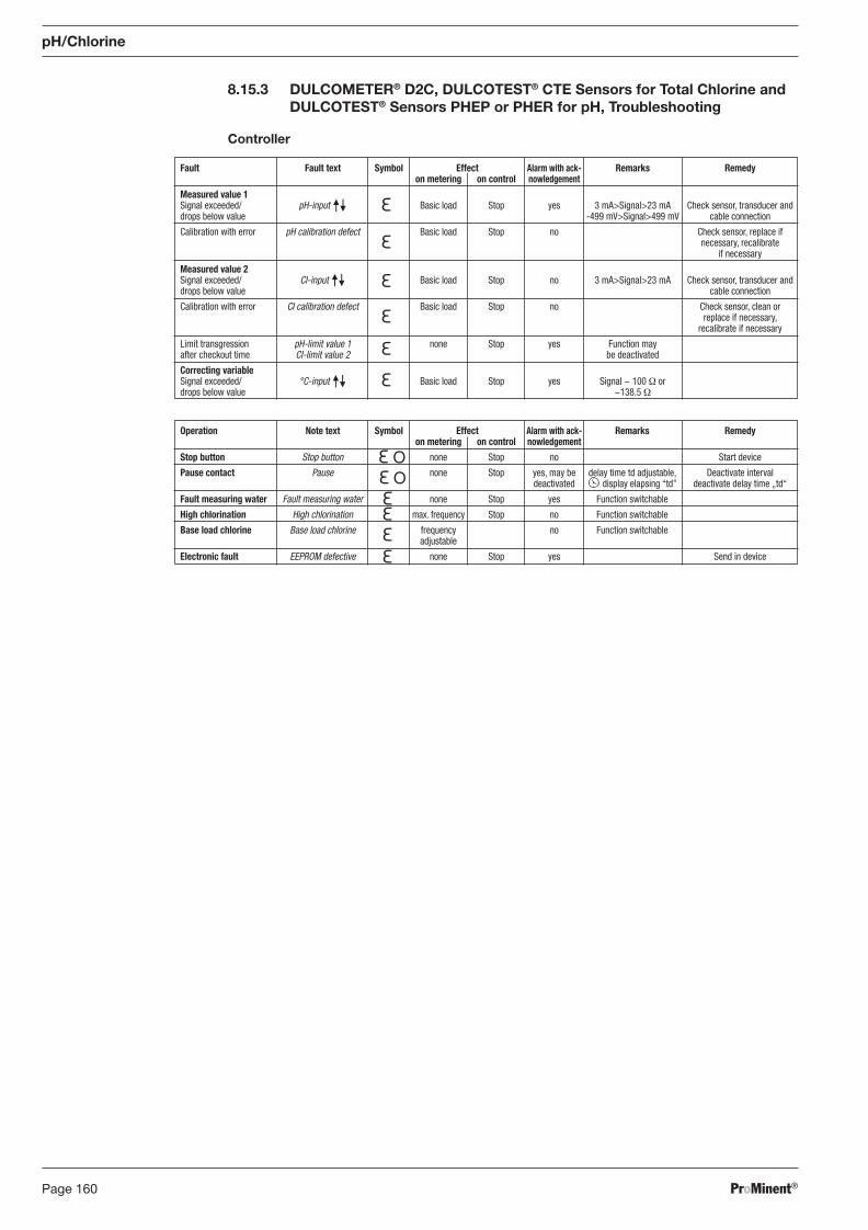
ProMinent®Page 160
Operation Note text Symbol Effect Alarm with ack- Remarks Remedy on metering on control nowledgement
Stop button Stop button none Stop no Start device
Pause contact Pause none Stop yes, may be delay time td adjustable, Deactivate interval deactivated display elapsing “td” deactivate delay time „td“
Fault measuring water Fault measuring water none Stop yes Function switchable
High chlorination High chlorination max. frequency Stop no Function switchable
Base load chlorine Base load chlorine frequency no Function switchable adjustable
Electronic fault EEPROM defective none Stop yes Send in device
8.15.3 DULCOMETER® D2C, DULCOTEST® CTE Sensors for Total Chlorine and DULCOTEST® Sensors PHEP or PHER for pH, Troubleshooting
Controller
Fault Fault text Symbol Effect Alarm with ack- Remarks Remedy on metering on control nowledgement
Measured value 1 Signal exceeded/ pH-input Basic load Stop yes 3 mA>Signal>23 mA Check sensor, transducer and drops below value -499 mV>Signal>499 mV cable connection
Calibration with error pH calibration defect Basic load Stop no Check sensor, replace if necessary, recalibrate if necessary
Measured value 2 Signal exceeded/ Cl-input Basic load Stop no 3 mA>Signal>23 mA Check sensor, transducer and drops below value cable connection
Calibration with error Cl calibration defect Basic load Stop no Check sensor, clean or replace if necessary, recalibrate if necessary
Limit transgression pH-limit value 1 none Stop yes Function may after checkout time Cl-limit value 2 be deactivated
Correcting variable Signal exceeded/ °C-input Basic load Stop yes Signal ~ 100 Ω or drops below value ~138.5 Ω
pH/Chlorine
BA_DR_001_02_09_GB.indd 160BA_DR_001_02_09_GB.indd 160 24.02.2009 12:24:11 Uhr24.02.2009 12:24:11 Uhr
ProMinent® Page 161
pH/Chlorine
8.15.4 DULCOMETER® D2C Measured Variable Chlorine, DULCOTEST® CTE Sensor for Total Chlorine and DULCOTEST® Sensor PHEP or PHER for pH, Maintenance
Controller
The DULCOMETER® controller type D2C for the measured variable pH/chlorine is maintenance-free.
Sensor
DULCOTEST® CTE sensor for total chlorine
IMPORTANT
• Service the sensor regularly to avoid overdosing within a control system, due to in cor-rect measured value.
• Observe the current national regulations for maintenance intervals.
• Do not touch the electrodes or allow them to come into contact with greasy substances.
• Never attempt to clean the membrane with acid/alkaline solutions, cleaning reagents or mechanical aids (brushes or similar).
Maintenance interval based on experience are:
• Potable, industrial, process and cooling water: depending on the specifi c conditions (1-4 weeks)
• Swimming pools: weekly
• Spa pools (whirlpools): daily
Maintenance Work
� Check the sensor regularly for dirt, algae and air bubbles. As far as possible, avoid contamina-tion of the membrane with solid particles, deposits etc. Eliminate air bubbles by increasing the fl ow rate.
� Check the displayed sensor value on the controller regularly according to the DPD-4 method using an appropriate chlorine measurement kit.
� If necessary, recalibrate the sensor.
� If calibration cannot be carried out properly, the membrane cap must be replaced and cali bra-tion must be repeated.
DULCOTEST® Sensor PHEP or PHER for pH, Maintenance
IMPORTANT
The sensor is to be regularly serviced to avoid any excess metering caused by a sensor failure!
Observe the valid national regulations for maintenance intervals!
Do not touch the electrodes or bring into contact with greasy substances!
Maintenance interval monthly
Maintenance Work
The sensor should regularly (once a month) undergo a visual check and be cleaned if necessary. If deposits on the glass electrode withstand cleaning with a soft, moistened cloth, the following cleaning agents may be used:
Kind of deposit Agent and duration of application
General deposits Non-abrasive household cleaner
Scale or metal hydroxides Diluted hydrochloric acid (approx. 0.1-3 %, 1-5 minutes)
Oil, grease Solvents, like alcohol or acetone
Biofouling Mixture of diluted hydrochloric acid and pepsin, several hours Solvents (e.g. acetone) must not be used to clean electrodes as they can demage the plastic stems.
It is essential that the sensor are rinsed thoroughly after having been cleaned.
BA_DR_001_02_09_GB.indd 161BA_DR_001_02_09_GB.indd 161 24.02.2009 12:24:11 Uhr24.02.2009 12:24:11 Uhr
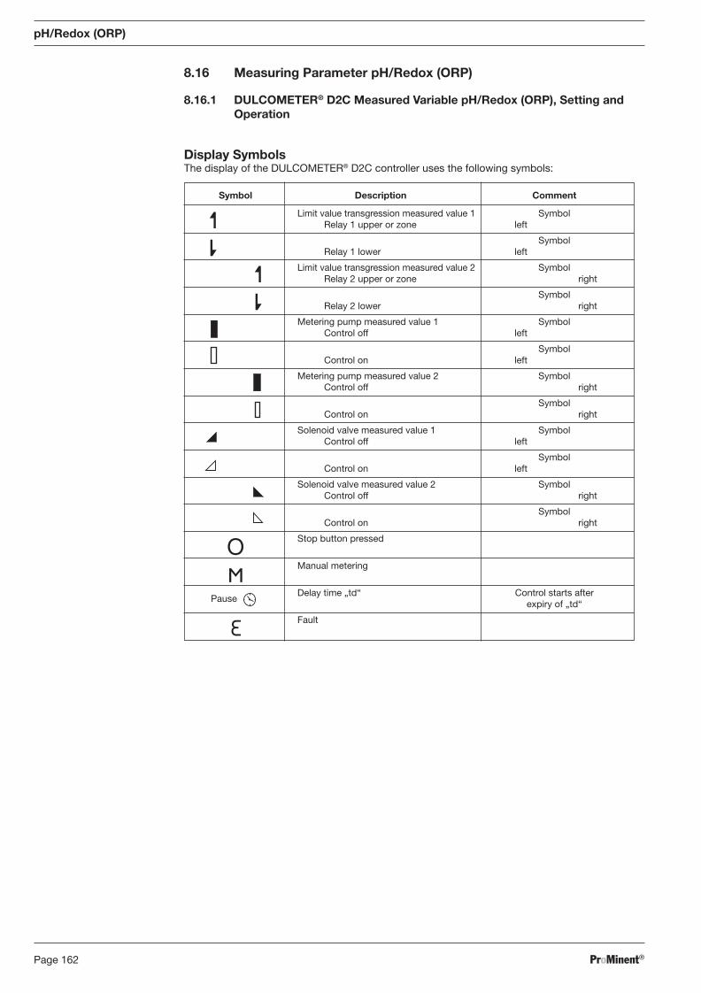
ProMinent®Page 162
8.16 Measuring Parameter pH/Redox (ORP)
8.16.1 DULCOMETER® D2C Measured Variable pH/Redox (ORP), Setting and Operation
Display Symbols The display of the DULCOMETER® D2C controller uses the following symbols:
Symbol Description Comment
Limit value transgression measured value 1 Symbol Relay 1 upper or zone left
Symbol Relay 1 lower left
Limit value transgression measured value 2 Symbol Relay 2 upper or zone right
Symbol Relay 2 lower right
Metering pump measured value 1 Symbol Control off left
Symbol Control on left
Metering pump measured value 2 Symbol Control off right
Symbol Control on right
Solenoid valve measured value 1 Symbol Control off left
Symbol Control on left
Solenoid valve measured value 2 Symbol Control off right
Symbol Control on right
Stop button pressed
Manual metering
Pause
Delay time „td“ Control starts after expiry of „td“
Fault
pH/Redox (ORP)
BA_DR_001_02_09_GB.indd 162BA_DR_001_02_09_GB.indd 162 24.02.2009 12:24:11 Uhr24.02.2009 12:24:11 Uhr
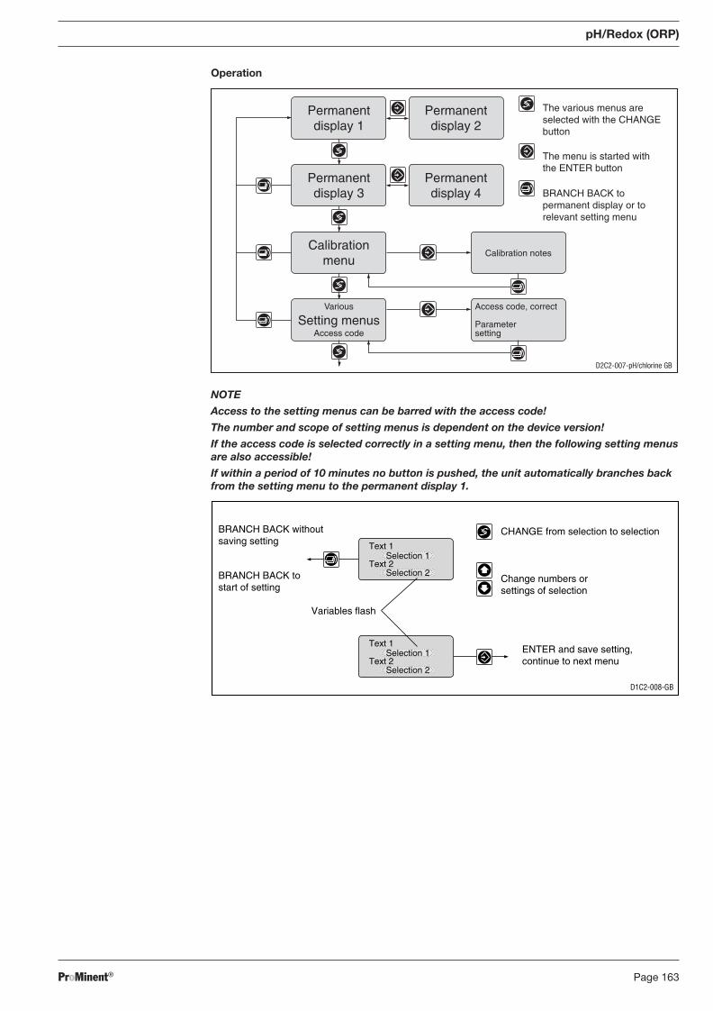
ProMinent® Page 163
pH/Redox (ORP)
Operation
Access code, correct
Parametersetting
Calibration notes
Permanentdisplay 1
Permanentdisplay 3
Calibrationmenu
Various
Access codeSetting menus
D2C2-007-pH/chlorine GB
The various menus areselected with the CHANGEbutton
The menu is started withthe ENTER button
BRANCH BACK topermanent display or torelevant setting menu
Permanentdisplay 2
Permanentdisplay 4
D1C2-008-GB
CHANGE from selection to selection
Change numbers orsettings of selection
Variables flash
ENTER and save setting,continue to next menu
BRANCH BACK withoutsaving setting
BRANCH BACK tostart of setting
Text 1
Text 2Selection 1
Selection 2
Text 1
Text 2Selection 1
Selection 2
NOTE
Access to the setting menus can be barred with the access code!
The number and scope of setting menus is dependent on the device version!
If the access code is selected correctly in a setting menu, then the following setting menus are also accessible!
If within a period of 10 minutes no button is pushed, the unit automatically branches back from the setting menu to the permanent display 1.
BA_DR_001_02_09_GB.indd 163BA_DR_001_02_09_GB.indd 163 24.02.2009 12:24:11 Uhr24.02.2009 12:24:11 Uhr
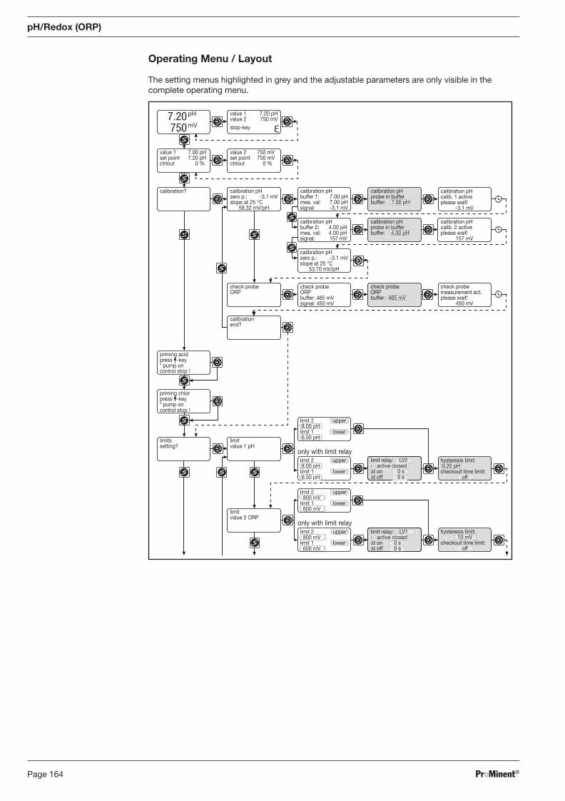
ProMinent®Page 164
Operating Menu / Layout
The setting menus highlighted in grey and the adjustable parameters are only visible in the complete operating menu.
pH/Redox (ORP)
priming acidpress -key* pump oncontrol stop !
limit 2 upper 800 mVlimit 1 lower 600 mV
limit 2 upper 800 mVlimit 1 lower 600 mV
only with limit relay
limitvalue 2 ORP
limit 2 upper 8.00 pHlimit 1 lower 6.50 pH
only with limit relay
limitssetting?
limitvalue 1 pH
calibrationend?
check probemeasurement act.please wait!
450 mV
check probeORPbuffer: 465 mVsignal: 450 mV
check probeORP
calibration pHcalib. 2 activeplease wait!
157 mV
calibration pHbuffer 2: 4.00 pHmea. val: 4.00 pHsignal: 157 mV
7.20 750
pH
mV
value 1 7.20 pHvalue 2 750 mVstop-key
value 2 750 mVset point 750 mVctrlout 0 %
value 1 7.00 pHset point 7.20 pHctrlout 0 %
calibration pHzero p.: -3.1 mVslope at 25 °C
58.32 mV/pH
calibration? calibration pHprobe in bufferbuffer: 7.00 pH
calibration pHprobe in bufferbuffer: 4.00 pH
check probeORPbuffer: 465 mV
limit relay: LV2- active closedΔt on 0 sΔt off 0 s
hysteresis limit: 0.20 pHcheckout time limit:
off
limit relay: LV1- active closedΔt on 0 sΔt off 0 s
hysteresis limit:10 mV
checkout time limit:off
priming chlorpress -key* pump oncontrol stop !
limit 2 upper 8.00 pHlimit 1 lower 6.50 pH
calibration pHbuffer 1: 7.00 pHmea. val: 7.00 pHsignal: -3.1 mV
calibration pHcalib. 1 activeplease wait!
-3.1 mV
calibration pHzero p.: -3.1 mVslope at 25 °C
53.70 mV/pH
BA_DR_001_02_09_GB.indd 164BA_DR_001_02_09_GB.indd 164 24.02.2009 12:24:11 Uhr24.02.2009 12:24:11 Uhr
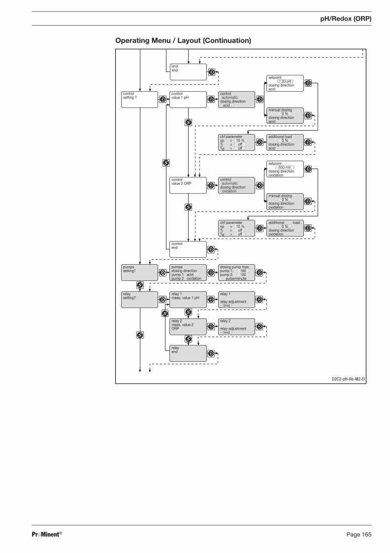
ProMinent® Page 165
pH/Redox (ORP)
Operating Menu / Layout (Continuation)
pumpssetting?
controlend
setpoint650 mV
dosing directionoxidation
controlvalue 2 ORP
setpoint7.20 pH
dosing directionacid
controlvalue 1 pH
controlsetting ?
relaysetting?
relay 1meas. value 1 pH
relay 2meas. value 2ORP
relayend
control automaticdosing direction acid
manual dosing0 %
dosing directionacid
ctrl parameterxp = 10 %Ti = offTd = off
additional load0 %
dosing directionacid
control automaticdosing direction oxidation
manual dosing0 %
dosing directionoxidation
additional load:0 %
dosing directionoxidation
ctrl parameterxp = 10 %Ti = offTd = off
pumpsdosing directionpump 1 acidpump 2 oxidation
dosing pump max.pump 1: 180pump 2: 180
pulse/minute
relay 1
relay adjustment- limit
relay 2
relay adjustment- limit
limitend
D2C2-pH-Re-M2-D
BA_DR_001_02_09_GB.indd 165BA_DR_001_02_09_GB.indd 165 24.02.2009 12:24:11 Uhr24.02.2009 12:24:11 Uhr
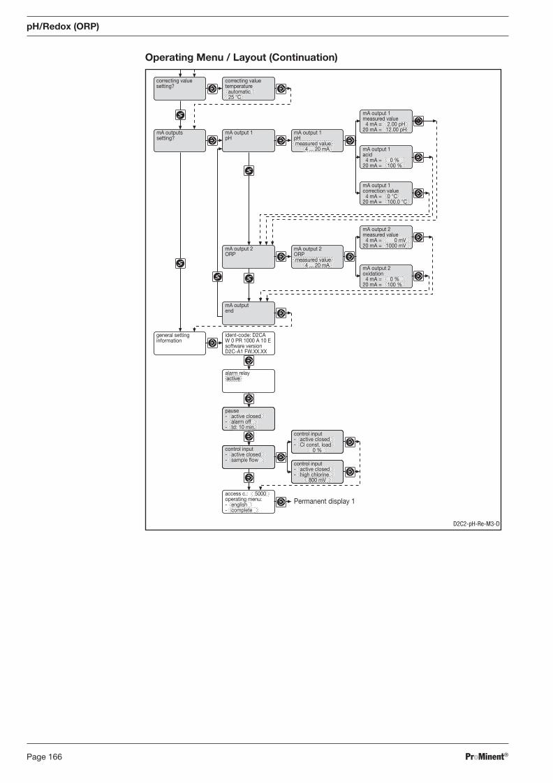
ProMinent®Page 166
Operating Menu / Layout (Continuation)
pH/Redox (ORP)
Permanent display 1
alarm relay active
general settinginformation
ident-code: D2CAW 0 PR 1000 A 10 Esoftware versionD2C-A1 FW.XX.XX
mA outputend
mA output 2ORP
correcting valuesetting?
mA outputssetting?
mA output 1pH
mA output 1pH measured value
4 ... 20 mA
mA output 1measured value 4 mA = 2.00 pH20 mA = 12.00 pH
mA output 1acid 4 mA = 0 %20 mA = 100 %
mA output 2measured value 4 mA = 0 mV20 mA = 1000 mV
mA output 2oxidation 4 mA = 0 %20 mA = 100 %
mA output 2ORP measured value
4 ... 20 mA
pause- active closed- alarm off- td: 10 min.
control input- active closed- sample flow
control input- active closed- Cl const. load
0 %
control input- active closed- high chlorine
800 mV
access c.: 5000operating menu:- english- complete
correcting valuetemperature automatic 25 °C
mA output 1correction value 4 mA = 0 °C20 mA = 100.0 °C
D2C2-pH-Re-M3-D
BA_DR_001_02_09_GB.indd 166BA_DR_001_02_09_GB.indd 166 24.02.2009 12:24:11 Uhr24.02.2009 12:24:11 Uhr
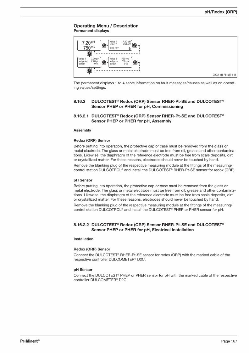
ProMinent® Page 167
pH/Redox (ORP)
Operating Menu / Description Permanent displays
The permanent displays 1 to 4 serve information on fault messages/causes as well as on op er at-ing values/settings.
8.16.2 DULCOTEST® Redox (ORP) Sensor RHER-Pt-SE and DULCOTEST® Sensor PHEP or PHER for pH, Commissioning
8.16.2.1 DULCOTEST® Redox (ORP) Sensor RHER-Pt-SE and DULCOTEST® Sensor PHEP or PHER for pH, Assembly
Assembly
Redox (ORP) Sensor
Before putting into operation, the protective cap or case must be removed from the glass or metal electrode. The glass or metal electrode must be free from oil, grease and other contamina-tions. Likewise, the diaphragm of the reference electrode must be free from scale deposits, dirt or crystallized matter. For these reasons, electrodes should never be touched by hand.
Remove the blanking plug of the respective measuring module at the fi ttings of the measuring/control station DULCOTROL® and install the DULCOTEST® RHER-Pt-SE sensor for redox (ORP).
pH Sensor
Before putting into operation, the protective cap or case must be removed from the glass or metal electrode. The glass or metal electrode must be free from oil, grease and other contamina-tions. Likewise, the diaphragm of the reference electrode must be free from scale deposits, dirt or crystallized matter. For these reasons, electrodes should never be touched by hand.
Remove the blanking plug of the respective measuring module at the fi ttings of the measuring/control station DULCOTROL® and install the DULCOTEST® PHEP or PHER sensor for pH.
8.16.2.2 DULCOTEST® Redox (ORP) Sensor RHER-Pt-SE and DULCOTEST® Sensor PHEP or PHER for pH, Electrical Installation
Installation
Redox (ORP) Sensor
Connect the DULCOTEST® RHER-Pt-SE sensor for redox (ORP) with the marked cable of the respective controller DULCOMETER® D2C.
pH Sensor
Connect the DULCOTEST® PHEP or PHER sensor for pH with the marked cable of the respective controller DULCOMETER® D2C.
7.20 750
pH
mV
value 1 7.20 pHvalue 2 750 mVstop-key
value 2 750 mVset point 750 mVctrlout 0 %
value 1 7.00 pHset point 7.20 pHctrlout 0 %
D2C2-pH-Re-MT-1-D
BA_DR_001_02_09_GB.indd 167BA_DR_001_02_09_GB.indd 167 24.02.2009 12:24:11 Uhr24.02.2009 12:24:11 Uhr
ProMinent®Page 168
8.16.2.3 DULCOTEST® Redox (ORP) Sensor RHER-Pt-SE and DULCOTEST® Sensor PHEP or PHER for pH, Running-In
Running-In
Redox (ORP) Sensor
The DULCOTEST® RHER-Pt-SE sensor for redox (ORP) must not be run-in. The DULCOTEST® RHER-Pt-SE sensor for redox (ORP) can be readily used.
pH Sensor
The DULCOTEST® PHEP or PHER sensor for pH must not be run-in. The DULCOTEST® PHEP or PHER sensor for pH can be readily used.
8.16.2.4 DULCOTEST® Redox (ORP) Sensor RHER-Pt-SE and DULCOTEST® Sensor PHEP or PHER for pH, Calibration
Redox (ORP) Sensor
Having connected the sensor to the transmitter by means of the sensor cable (taking care that connectors and cable remain absolutely dry), dip the sensor into a redox standardizing solution, e.g. of 465 mV. The reading should reach or exceed this value within not more than 30 seconds. If the reading rises rather sluggishly or falls short more than 20 mV, clean the sensor and repeat check. If again unsuccessful, replace the sensor with a new one.
pH Sensor
Since pH sensors are subject to certain manufacturing tolerances, they must be tuned to the pertinent pH transmitter. The adjustment intervals depend on relevant operating conditions. They can vary from a few days to up to 8 weeks. Having connected the sensor to the transmitter by means of the sensor cable (taking care that connectors and cable remain absolutely dry), dip the sensor into a pH 7 standardizing solution and adjust transmitter exactly to read this value. Remove the sensor, rinse it with water, preferably distilled water, and dry it by swabbing it with soft, non-fl uffi ng tissue paper.
IMPORTANT
Do not rub since this might cause static electricity and false readings.
Immerse the sensor in a buffer solution differing by a least 2 pH from pH 7 and calibrate after the value on the display has stabilised. If within 30 seconds a steady-state value is not produced or calibration has proved impossible, clean sensor and repeat calibration. If again unsuccessful, replace sensor with a new one.
Calibration D2C
Calibration of the pH Sensor
The calibration of the pH sensor uses a two-point calibration method (zero point, slope). As buffer pH 7 (zero point calibration) and pH 4 (slope calibration) are factory-set. If other buffers are to be used, the defaults in the complete operating menu (menu A, B) may be altered. During cal i-bra tion control is stopped and metering is reduced to the set base load. The output 0/4...20 mA (meas ur ing value) will be frozen. After successful calibration, all fault determinations relating to the meas ur ing value are started again. The current probe data (zero point/slope) will be displayed.
pH/Redox (ORP)
BA_DR_001_02_09_GB.indd 168BA_DR_001_02_09_GB.indd 168 24.02.2009 12:24:11 Uhr24.02.2009 12:24:11 Uhr
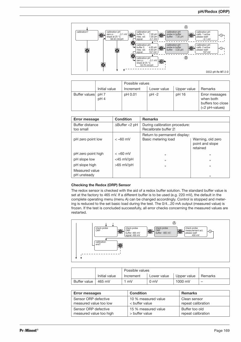
ProMinent® Page 169
pH/Redox (ORP)
Checking the Redox (ORP) Sensor
The redox sensor is checked with the aid of a redox buffer solution. The standard buffer value is set at the factory to 465 mV. If a different buffer is to be used (e.g. 220 mV), the default in the complete operating menu (menu A) can be changed accordingly. Control is stopped and me ter-ing is reduced to the set basic load during the test. The 0/4...20 mA output (measured value) is frozen. If the test is concluded successfully, all error checks concerning the measured values are restarted.
Possible values
Initial value Increment Lower value Upper value Remarks
Buffer values pH 7 pH 0.01 pH -2 pH 16 Error messages pH 4 when both
buffers too close (<2 pH-values)
calibration pHzero p.: -3.1 mVslope at 25 °C
53.70 mV/pH
calibration pHcalib. 2 activeplease wait!
157 mV
calibration pHbuffer 2: 4.00 pHmea. val: 4.00 pHsignal: 157 mV
calibration pHcalib. 1 activeplease wait!
-3.1 mV
calibration pHbuffer 1: 7.00 pHmea. val: 7.00 pHsignal: -3.1 mV
calibration pHzero p.: -3.1 mVslope at 25 °C
58.32 mV/pH
calibration? calibration pHprobe in bufferbuffer: 7.00 pH
calibration pHprobe in bufferbuffer: 4.00 pH
D2C2-pH-Re-MT-2-D
A
B
calibrationend?
check probemeasurement act.please wait!
450 mV
check probeORPbuffer: 465 mVsignal: 450 mV
check probeORP
check probeORPbuffer: 465 mV
A
Possible values
Initial value Increment Lower value Upper value Remarks
Buffer value 465 mV 1 mV 0 mV 1000 mV –
Error messages Condition Remarks
Sensor ORP defective 10 % measured value Clean sensor measured value too low < buffer value repeat calibration
Sensor ORP defective 15 % measured value Buffer too old measured value too high > buffer value repeat calibration
Error message Condition Remarks
Buffer distance ΔBuffer <2 pH During calibration procedure: too small Recalibrate buffer 2!
Return to permanent display: pH zero point low < –60 mV Basic metering load Warning, old zero point and slope retained
pH zero point high < +60 mV „ „
pH slope low <45 mV/pH „ „
pH slope high >65 mV/pH „ „
Measured value pH unsteady „
BA_DR_001_02_09_GB.indd 169BA_DR_001_02_09_GB.indd 169 24.02.2009 12:24:12 Uhr24.02.2009 12:24:12 Uhr

ProMinent®Page 170
Operation Note text Symbol Effect Alarm with ack- Remarks Remedy on metering on control nowledgement Stop button Stop button none Stop no Start device
Pause contact Pause none Stop yes, may be delay time td adjustable, deactivate interval deactivated display elapsing „td“ deactivate delay time „td“
Priming Stop control Stop no reset via Stop button
Error sample fl ow Error sample fl ow none Stop yes Function switchable
High chlorination High chlorine max. frequency Stop no Function switchable
Basic load chlorine Cl const. load frequency no Function switchable adjustable
Electronic fault EEPROM defective none Stop yes send in device
8.16.3 DULCOMETER® D2C, DULCOTEST® Redox (ORP) Sensor RHER-Pt-SE and DULCOTEST® Sensor PHEP or PHER for pH, Troubleshooting
Controller
Fault Fault text Symbol Effect Alarm with ack- Remarks Remedy on metering on control nowledgement Measured value 1 Signal exceeded/ pH-input Basic load Stop yes 3 mA>Signal>23 mA Check sensor, transducer and drops below value -499 mV>Signal>499 mV cable connection
Calibration with error pH-calibration defect Basic load Stop no Check sensor, replace if necessary, recalibrate if necessary
Measured value 2 Signal exceeded/ check mV-input Basic load Stop yes 3 mA>Signal>23 mA Check sensor, transducer and drops below value cable connection
Calibration with error sensor ORP Basic load Stop no Check sensor, clean or defective replace if necessary, recalibrate if necessary
Limit transgression pH-limit value 1 none Stop yes Function switchable after checkout time mV-limit value 2
Correcting value Signal exceeded/ °C-input Basic load pH Stop pH yes Signal ~ 100 Ω or drops below value ~ 138.5 Ω
pH/Redox (ORP)
BA_DR_001_02_09_GB.indd 170BA_DR_001_02_09_GB.indd 170 24.02.2009 12:24:12 Uhr24.02.2009 12:24:12 Uhr
ProMinent® Page 171
pH/Redox (ORP)
8.16.4 DULCOMETER® D2C Measured Variable pH, Redox (ORP), DULCOTEST® Redox (ORP) Sensor RHER-Pt-SE and DULCOTEST® Sensor PHEP or PHER for pH, Maintenance
Controller
The DULCOMETER® controller type D2C for the measured variable pH/redox (ORP) is main te nance-free.
Assembly
Sensor: DULCOTEST® sensor RHER-Pt-SE / DULCOTEST® sensor PHEP or PHER
IMPORTANT
� The sensor is to be regularly serviced to avoid any excess metering caused by a sensor failure!
� Observe the valid national regulations for maintenance intervals! � Do not touch the electrodes or bring into contact with greasy substances!
Maintenance interval monthly
Maintenance Work
All sensors should regularly (once a month) undergo a visual check and be cleaned if necessary. If deposits on the glass electrode withstand cleaning with a soft, moistened cloth, the following cleaning agents may be used:
Kind of deposit Agent and duration of application
General deposits Non-abrasive household cleaner
Scale or metal hydroxides Diluted hydrochloric acid (approx. 0.1-3 %, 1-5 minutes)
Oil, grease Solvents, like alcohol or acetone
Biofouling Mixture of diluted hydrochloric acid and pepsin, several hours Solvents (e.g. acetone) must not be used to clean electrodes as they can demage the plastic stems.
It is essential that the sensors are rinsed thoroughly after having been cleaned. In addition, the metal surfaces of redox sensors may be cleaned by sanding and polishing. If the laterally arranged ceramic diaphragm of the reference electrode is blocked, it may be cleaned like the glass electrode. In addition it may be cleaned by cautious scraping with a fi nger nail, a razor blade or a fi ne fi le, but care must be taken that the diaphragm is not scratched.
BA_DR_001_02_09_GB.indd 171BA_DR_001_02_09_GB.indd 171 24.02.2009 12:24:12 Uhr24.02.2009 12:24:12 Uhr

ProMinent®Page 172
8.17 Measuring Parameter pH/Chlorine Dioxide
8.17.1 DULCOMETER® D2C Measured Variable pH/Chlorine Dioxide, Setting and Operation
Display Symbols The display of the DULCOMETER® D2C controller uses the following symbols:
Symbol Description Comment
Limit value transgression measured value 1 Symbol Relay 1 upper or zone left
Symbol Relay 1 lower left
Limit value transgression measured value 2 Symbol Relay 2 upper or zone right
Symbol Relay 2 lower right
Metering pump measured value 1 Symbol Control off left
Symbol Control on left
Metering pump measured value 2 Symbol Control off right
Symbol Control on right
Solenoid valve measured value 1 Symbol Control off left
Symbol Control on left
Solenoid valve measured value 2 Symbol Control off right
Symbol Control on right
Stop button pressed
Manual metering
Pause
Delay time „td“ Control starts after expiry of „td“
Fault
pH/Chlorine Dioxide
BA_DR_001_02_09_GB.indd 172BA_DR_001_02_09_GB.indd 172 24.02.2009 12:24:12 Uhr24.02.2009 12:24:12 Uhr
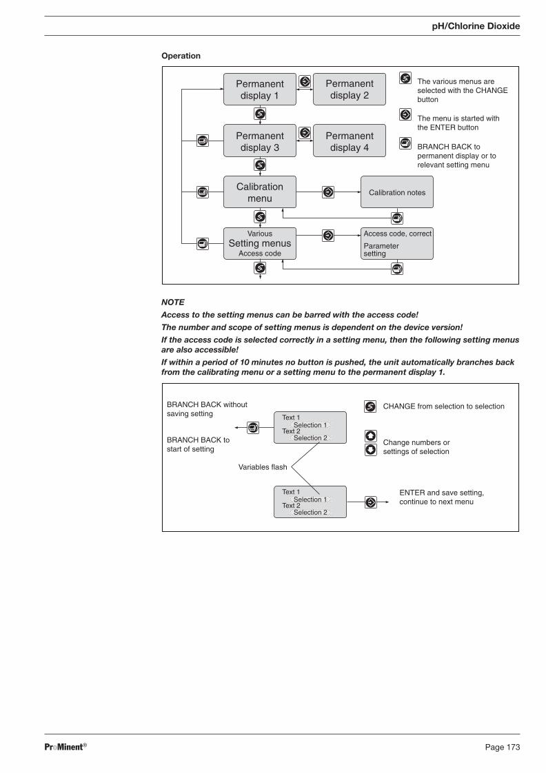
ProMinent® Page 173
pH/Chlorine Dioxide
Operation
NOTE
Access to the setting menus can be barred with the access code!
The number and scope of setting menus is dependent on the device version!
If the access code is selected correctly in a setting menu, then the following setting menus are also accessible!
If within a period of 10 minutes no button is pushed, the unit automatically branches back from the calibrating menu or a setting menu to the permanent display 1.
BA_DR_001_02_09_GB.indd 173BA_DR_001_02_09_GB.indd 173 24.02.2009 12:24:12 Uhr24.02.2009 12:24:12 Uhr
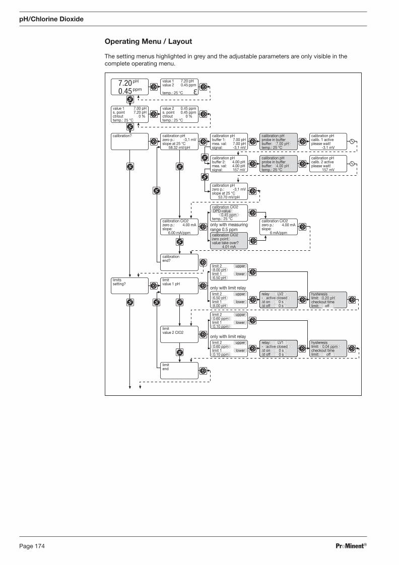
ProMinent®Page 174
Operating Menu / Layout
The setting menus highlighted in grey and the adjustable parameters are only visible in the complete operating menu.
pH/Chlorine Dioxide
BA_DR_001_02_09_GB.indd 174BA_DR_001_02_09_GB.indd 174 24.02.2009 12:24:12 Uhr24.02.2009 12:24:12 Uhr
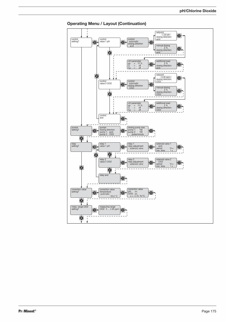
ProMinent® Page 175
pH/Chlorine Dioxide
Operating Menu / Layout (Continuation)
BA_DR_001_02_09_GB.indd 175BA_DR_001_02_09_GB.indd 175 24.02.2009 12:24:12 Uhr24.02.2009 12:24:12 Uhr
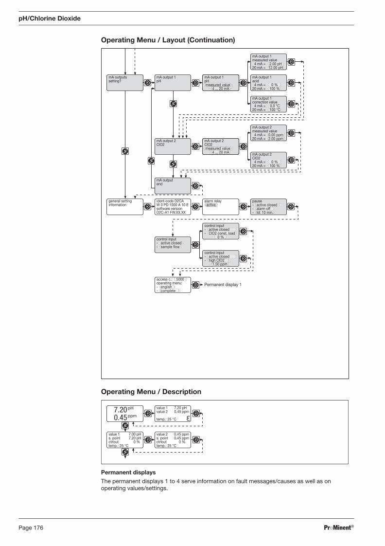
ProMinent®Page 176
Operating Menu / Layout (Continuation)
pH/Chlorine Dioxide
7.200.45
pH
ppm
value 1 7.20 pHvalue 2 0.45 ppm
temp.: 25 °C
value 2 0.45 ppms. point 0.45 ppmctrlout 0 %temp.: 25 °C
value 1 7.00 pHs. point 7.20 pHctrlout 0 %temp.: 25 °C
Operating Menu / Description
Permanent displays
The permanent displays 1 to 4 serve information on fault messages/causes as well as on op er at ing values/settings.
BA_DR_001_02_09_GB.indd 176BA_DR_001_02_09_GB.indd 176 24.02.2009 12:24:12 Uhr24.02.2009 12:24:12 Uhr
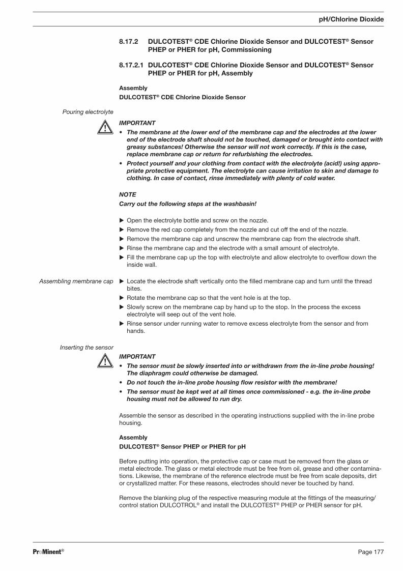
ProMinent® Page 177
8.17.2 DULCOTEST® CDE Chlorine Dioxide Sensor and DULCOTEST® Sensor PHEP or PHER for pH, Commissioning
8.17.2.1 DULCOTEST® CDE Chlorine Dioxide Sensor and DULCOTEST® Sensor PHEP or PHER for pH, Assembly
Assembly
DULCOTEST® CDE Chlorine Dioxide Sensor
Pouring electrolyte
IMPORTANT
• The membrane at the lower end of the membrane cap and the electrodes at the lower end of the electrode shaft should not be touched, damaged or brought into contact with greasy substances! Otherwise the sensor will not work correctly. If this is the case, replace membrane cap or return for refurbishing the electrodes.
• Protect yourself and your clothing from contact with the electrolyte (acid!) using ap pro-pri ate protective equipment. The electrolyte can cause irritation to skin and damage to clothing. In case of contact, rinse immediately with plenty of cold water.
NOTE
Carry out the following steps at the washbasin!
� Open the electrolyte bottle and screw on the nozzle.
� Remove the red cap completely from the nozzle and cut off the end of the nozzle.
� Remove the membrane cap and unscrew the membrane cap from the electrode shaft.
� Rinse the membrane cap and the electrode with a small amount of electrolyte.
� Fill the membrane cap up the top with electrolyte and allow electrolyte to overfl ow down the inside wall.
Assembling membrane cap � Locate the electrode shaft vertically onto the fi lled membrane cap and turn until the thread bites.
� Rotate the membrane cap so that the vent hole is at the top.
� Slowly screw on the membrane cap by hand up to the stop. In the process the excess elec tro lyte will seep out of the vent hole.
� Rinse sensor under running water to remove excess electrolyte from the sensor and from hands.
Inserting the sensor
IMPORTANT
• The sensor must be slowly inserted into or withdrawn from the in-line probe housing! The diaphragm could otherwise be damaged.
• Do not touch the in-line probe housing fl ow resistor with the membrane!
• The sensor must be kept wet at all times once commissioned - e.g. the in-line probe housing must not be allowed to run dry.
Assemble the sensor as described in the operating instructions supplied with the in-line probe housing.
Assembly
DULCOTEST® Sensor PHEP or PHER for pH
Before putting into operation, the protective cap or case must be removed from the glass or metal electrode. The glass or metal electrode must be free from oil, grease and other contamina-tions. Likewise, the membrane of the reference electrode must be free from scale deposits, dirt or crystallized matter. For these reasons, electrodes should never be touched by hand.
Remove the blanking plug of the respective measuring module at the fi ttings of the measuring/control station DULCOTROL® and install the DULCOTEST® PHEP or PHER sensor for pH.
pH/Chlorine Dioxide
BA_DR_001_02_09_GB.indd 177BA_DR_001_02_09_GB.indd 177 24.02.2009 12:24:12 Uhr24.02.2009 12:24:12 Uhr
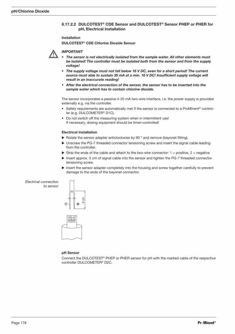
ProMinent®Page 178
8.17.2.2 DULCOTEST® CDE Sensor and DULCOTEST® Sensor PHEP or PHER for pH, Electrical Installation
Installation
DULCOTEST® CDE Chlorine Dioxide Sensor
IMPORTANT
• The sensor is not electrically isolated from the sample water. All other elements must be isolated! The controller must be isolated both from the sensor and from the supply voltage!
• The supply voltage must not fall below 16 V DC, even for a short period! The current source must able to sustain 35 mA at a min. 16 V DC! Insuffi cient supply voltage will result in an inaccurate reading!
• After the electrical connection of the sensor, the sensor has to be inserted into the sample water which has to contain chlorine dioxide.
The sensor incorporates a passive 4-20 mA two-wire interface, i.e. the power supply is provided externally e.g. via the controller.
• Safety requirements are automatically met if the sensor is connected to a ProMinent® control-ler (e.g. DULCOMETER® D1C).
• Do not switch off the measuring system when in intermittent use! If necessary, dosing equipment should be timer-controlled!
Electrical Installation
� Rotate the sensor adapter anticlockwise by 90 º and remove (bayonet fi tting).
� Unscrew the PG-7 threaded connector tensioning screw and insert the signal cable leading from the controller.
� Strip the ends of the cable and attach to the two-wire connector: 1 = positive, 2 = negative
� Insert approx. 5 cm of signal cable into the sensor and tighten the PG-7 threaded connector tensioning screw.
� Insert the sensor adapter completely into the housing and screw together carefully to prevent damage to the ends of the bayonet connector.
Electrical connection to sensor
1 2
5 cm
pH Sensor
Connect the DULCOTEST® PHEP or PHER sensor for pH with the marked cable of the respective controller DULCOMETER® D2C.
pH/Chlorine Dioxide
BA_DR_001_02_09_GB.indd 178BA_DR_001_02_09_GB.indd 178 24.02.2009 12:24:12 Uhr24.02.2009 12:24:12 Uhr
ProMinent® Page 179
pH/Chlorine Dioxide
8.17.2.3 DULCOTEST® CDE Chlorine Dioxide Sensor and DULCOTEST® Sensor PHEP or PHER for pH, Running-In
Running-In
DULCOTEST® CDE Chlorine Dioxide Sensor
IMPORTANT
• The sensor must be used only in surfactant-free water or solutions!
• When operating the sensor, the sample water must permanently contain chlorine dioxide.
• Do not switch off the measuring system during interval operation! After operation without chlorine dioxide, running-in periods are to be reckoned with. If required, switch on metering unit time-delayed! If no chlorine dioxide is metered for a longer period of time, the sensor must be disconnected from the power supply and stored dry.
Running-In Period
The sensor requires a run-in period before it will display stable readings.
Commissioning: 2 - 6 h Re-commissioning: 1 - 3 h Diaphragm-/electrolyte replacement: approx. 0.5 h
pH Sensor
The DULCOTEST® PHEP or PHER sensor for pH must not be run-in. The DULCOTEST® PHEP or PHER sensor for pH can be readily used.
8.17.2.4 DULCOTEST® CDE Chlorine Dioxide Sensor and DULCOTEST® Sensor PHEP or PHER for pH, Calibration
Calibration
DULCOTEST® CDE Chlorine Dioxide Sensor
The sensor can be calibrated after the run-in period.
IMPORTANT
• A slope test must be carried out after replacing the diaphragm cap or electrolyte!
• Slope tests must be carried out at regular intervals to ensure correct functioning of the sensor! For testing drinking water, calibration of the sensor every 3 - 4 weeks is suffi ci-ent.
• Avoid incorrect dosing due to air bubbles in the water. Air bubbles clinging to the sensor diaphragm can reduce the measured variable and thereby lead to overdosing.
• Observe applicable national directives for calibration intervals!
Preconditions • Constant fl ow to the in-line probe housing.
• Constant sample water temperature.
• Same sample water and sensor temperatures (wait approx. 15 min.).
Zero Point Calibration
If a ProMinent controller is being used to operate the sensor there is no need for zero point calibration. Zero point calibration should be carried out, however, if operating the sensor in the lower measurement range, or if using the 0.5 ppm variant.
Preconditions • The sensor has been run in.
• Flow to the in-line probe housing is constant and complies with technical data.
� Insert the sensor into a container of clean, ozone- and ClO2-free water.
� Stir with the sensor until the measured variable displayed at the controller has remained stable for 5 min.
� Calibrate the controller to zero in accordance with the operating instructions.
� Replace sensor into the in-line probe housing (DGM; DLG).
BA_DR_001_02_09_GB.indd 179BA_DR_001_02_09_GB.indd 179 24.02.2009 12:24:12 Uhr24.02.2009 12:24:12 Uhr
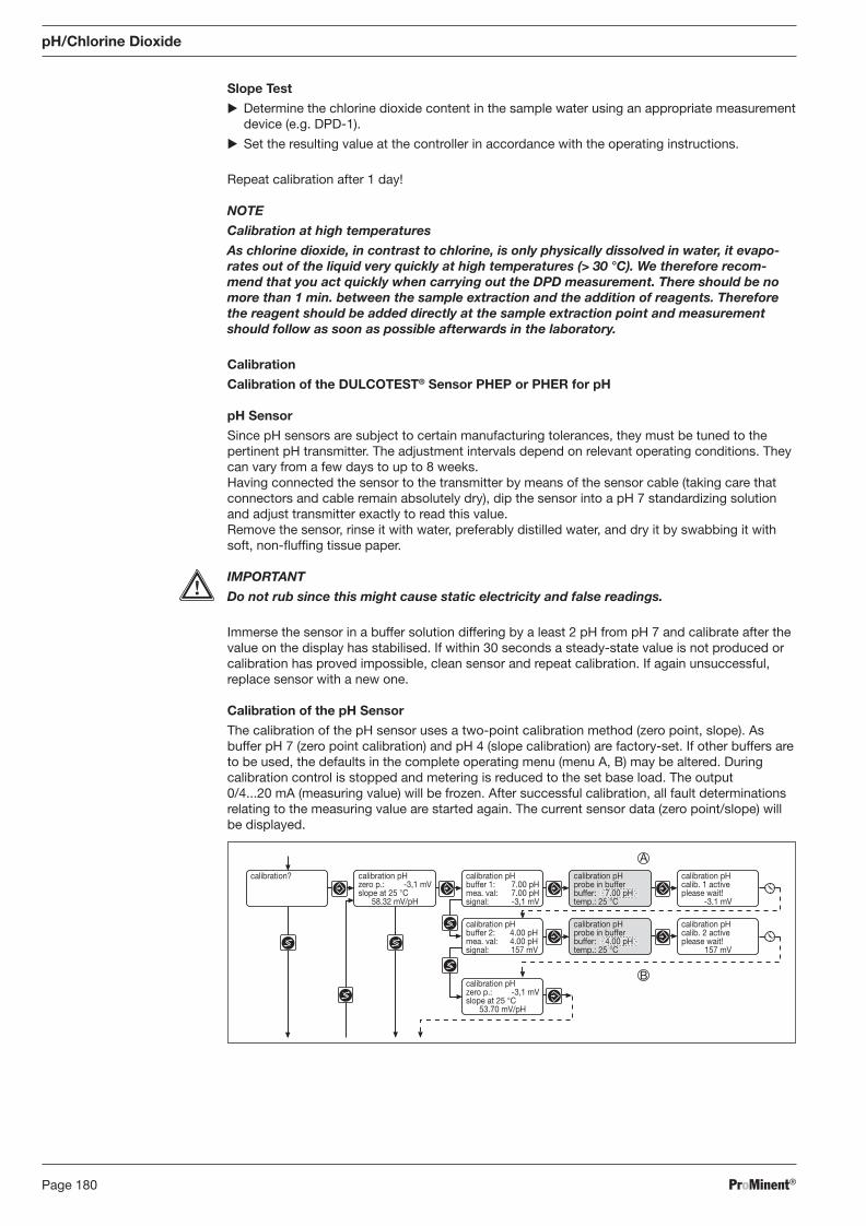
ProMinent®Page 180
calibration pHzero p.: -3,1 mVslope at 25 °C
58.32 mV/pH
calibration? calibration pHbuffer 1: 7.00 pHmea. val: 7.00 pHsignal: -3,1 mV
calibration pHcalib. 1 activeplease wait!
-3.1 mV
calibration pHbuffer 2: 4.00 pHmea. val: 4.00 pHsignal: 157 mV
calibration pHcalib. 2 activeplease wait!
157 mV
calibration pHzero p.: -3,1 mVslope at 25 °C
53.70 mV/pH
calibration pHprobe in bufferbuffer: 7.00 pHtemp.: 25 °C
calibration pHprobe in bufferbuffer: 4.00 pHtemp.: 25 °C
A
B
Slope Test
� Determine the chlorine dioxide content in the sample water using an appropriate measurement device (e.g. DPD-1).
� Set the resulting value at the controller in accordance with the operating instructions.
Repeat calibration after 1 day!
NOTE
Calibration at high temperatures
As chlorine dioxide, in contrast to chlorine, is only physically dissolved in water, it evapo-rates out of the liquid very quickly at high temperatures (> 30 °C). We therefore recom-mend that you act quickly when carrying out the DPD measurement. There should be no more than 1 min. between the sample extraction and the addition of reagents. Therefore the reagent should be added directly at the sample extraction point and measurement should follow as soon as possible afterwards in the laboratory.
Calibration
Calibration of the DULCOTEST® Sensor PHEP or PHER for pH
pH Sensor
Since pH sensors are subject to certain manufacturing tolerances, they must be tuned to the pertinent pH transmitter. The adjustment intervals depend on relevant operating conditions. They can vary from a few days to up to 8 weeks. Having connected the sensor to the transmitter by means of the sensor cable (taking care that connectors and cable remain absolutely dry), dip the sensor into a pH 7 standardizing solution and adjust transmitter exactly to read this value. Remove the sensor, rinse it with water, preferably distilled water, and dry it by swabbing it with soft, non-fl uffi ng tissue paper.
IMPORTANT
Do not rub since this might cause static electricity and false readings.
Immerse the sensor in a buffer solution differing by a least 2 pH from pH 7 and calibrate after the value on the display has stabilised. If within 30 seconds a steady-state value is not produced or calibration has proved impossible, clean sensor and repeat calibration. If again unsuccessful, replace sensor with a new one.
Calibration of the pH Sensor
The calibration of the pH sensor uses a two-point calibration method (zero point, slope). As buffer pH 7 (zero point calibration) and pH 4 (slope calibration) are factory-set. If other buffers are to be used, the defaults in the complete operating menu (menu A, B) may be altered. During calibration control is stopped and metering is reduced to the set base load. The output 0/4...20 mA (meas ur ing value) will be frozen. After successful calibration, all fault determinations relating to the meas ur ing value are started again. The current sensor data (zero point/slope) will be displayed.
pH/Chlorine Dioxide
BA_DR_001_02_09_GB.indd 180BA_DR_001_02_09_GB.indd 180 24.02.2009 12:24:12 Uhr24.02.2009 12:24:12 Uhr
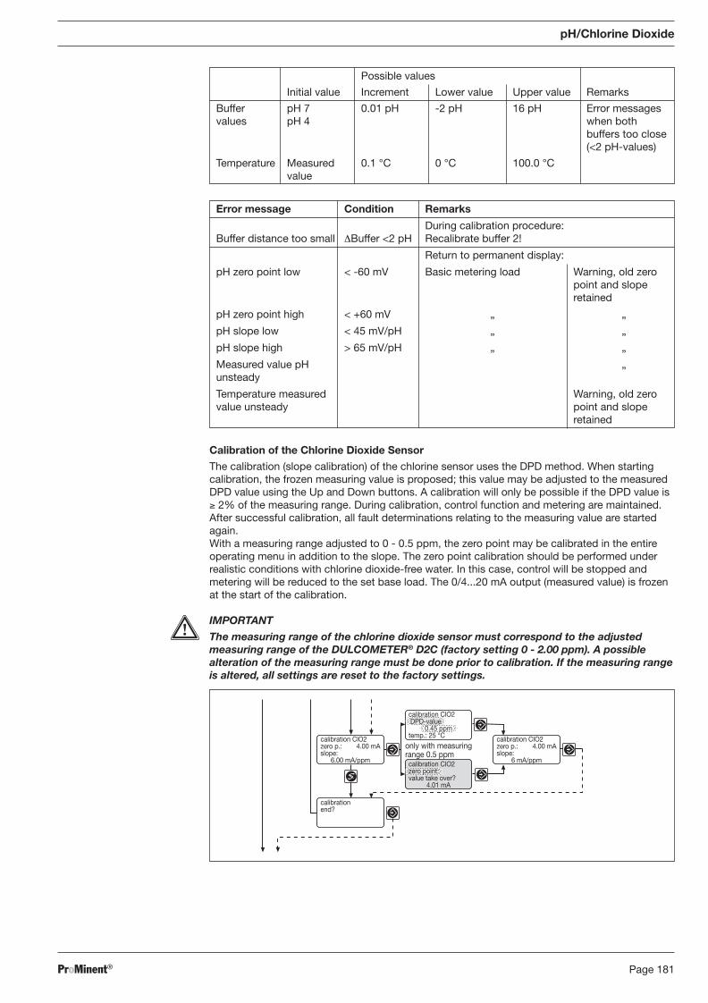
ProMinent® Page 181
pH/Chlorine Dioxide
Calibration of the Chlorine Dioxide Sensor
The calibration (slope calibration) of the chlorine sensor uses the DPD method. When starting calibration, the frozen measuring value is proposed; this value may be adjusted to the measured DPD value using the Up and Down buttons. A calibration will only be possible if the DPD value is ≥ 2% of the measuring range. During calibration, control function and metering are maintained. After successful calibration, all fault determinations relating to the measuring value are started again. With a measuring range adjusted to 0 - 0.5 ppm, the zero point may be calibrated in the entire operating menu in addition to the slope. The zero point calibration should be performed under realistic conditions with chlorine dioxide-free water. In this case, control will be stopped and metering will be reduced to the set base load. The 0/4...20 mA output (measured value) is frozen at the start of the calibration.
IMPORTANT
The measuring range of the chlorine dioxide sensor must correspond to the adjusted measuring range of the DULCOMETER® D2C (factory setting 0 - 2.00 ppm). A possible alteration of the measuring range must be done prior to calibration. If the measuring range is altered, all settings are reset to the factory settings.
Possible values
Initial value Increment Lower value Upper value Remarks
Buffer pH 7 0.01 pH -2 pH 16 pH Error messages values pH 4 when both
buffers too close (<2 pH-values)
Temperature Measured 0.1 °C 0 °C 100.0 °C value
Error message Condition Remarks
During calibration procedure: Buffer distance too small ΔBuffer <2 pH Recalibrate buffer 2!
Return to permanent display:
pH zero point low < -60 mV Basic metering load Warning, old zero point and slope retained
pH zero point high < +60 mV „ „
pH slope low < 45 mV/pH „ „
pH slope high > 65 mV/pH „ „
Measured value pH „ unsteady
Temperature measured Warning, old zero value unsteady point and slope retained
BA_DR_001_02_09_GB.indd 181BA_DR_001_02_09_GB.indd 181 24.02.2009 12:24:12 Uhr24.02.2009 12:24:12 Uhr
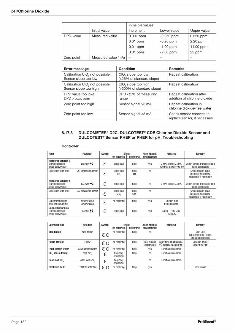
ProMinent®Page 182
8.17.3 DULCOMETER® D2C, DULCOTEST® CDE Chlorine Dioxide Sensor and DULCOTEST® Sensor PHEP or PHER for pH, Troubleshooting
Controller
Fault Fault text Symbol Effect Alarm with ack- Remarks Remedy on metering on control nowledgement Measured variable 1 Signal exceeded/ pH input Basic load Stop yes 3 mA>signal>23 mA Check sensor, transducer and drops below value -499 mV>signal>499 mV cable connection
Calibration with error pH calibration defect Basic load Stop no Check sensor, clean, pH pH replace if necessary, recalibrate if necessary
Measured variable 2 Signal exceeded/ CD input Basic load Stop no 3 mA>signal>23 mA Check sensor, transducer and drops below value cable connection
Calibration with error CD calibration defect Basic load Stop no Check sensor, clean, ClO2 ClO2 replace if necessary, recalibrate if necessary
Limit transgression pH limit value no metering Stop yes Function may after checkout time CD limit value be deactivated
Correcting variable Signal exceeded/ °C input Basic load Stop yes Signal ~ 100 Ω or drops below value ~138.5 Ω
Operating step Note text Symbol Effect Alarm with ack- Remarks Remedy on metering on control nowledgement Stop button Stop button no metering Stop no Start unit, run-on time “td” stops, shock dosing stops
Pause contact Pause no metering Stop yes, may be delay time td adjustable, Deselect pause, deactivated display elapsing “td” delay time “td”
Fault sample water Fault sample water no metering Stop yes Function switchable
ClO2 shock dosing High ClO2 frequency Stop no Function switchable adjustable
Base load ClO2 Base load ClO2 frequency no Function switchable adjustable
Electronic fault EEPROM defective no metering Stop yes send in unit
pH/Chlorine Dioxide
Error message Condition Remarks
Calibration ClO2 not possible! ClO2 slope too low Repeat calibration Sensor slope too low (<25% of standard slope)
Calibration ClO2 not possible! ClO2 slope too high Repeat calibration Sensor slope too high (>300% of standard slope)
DPD value too low! DPD <2 % of measuring Repeat calibration after DPD > x.xx ppm range addition of chlorine dioxide
Zero point too high Sensor signal >5 mA Repeat calibration in chlorine dioxide-free water
Zero point too low Sensor signal <3 mA Check sensor connection replace sensor, if necessary
Possible values
Initial value Increment Lower value Upper value
DPD-value Measured value 0.001 ppm -0.050 ppm 0.550 ppm
0.01 ppm -0.20 ppm 2,20 ppm
0.01 ppm -1.00 ppm 11.00 ppm
0.01 ppm -2.00 ppm 22 ppm
Zero point Measured value (mA) – – –
BA_DR_001_02_09_GB.indd 182BA_DR_001_02_09_GB.indd 182 24.02.2009 12:24:12 Uhr24.02.2009 12:24:12 Uhr
ProMinent® Page 183
pH/Chlorine Dioxide
8.17.4 DULCOMETER® D2C Measured Variable pH/Chlorine Dioxide, DULCOTEST® CDE Chlorine Dioxide Sensor and DULCOTEST® Sensor PHEP or PHER for pH, Maintenance
Controller
The DULCOMETER® controller type D2C for the measured variable pH/chlorine dioxide is main te nance-free.
Sensor
DULCOTEST® CDE Chlorine Dioxide Sensor
IMPORTANT • The sensor must be regularly serviced in order to avoid overdosing due to sensor failure! • Observe applicable national directives for servicing intervals! • Do not touch the electrodes or bring them into contact with greasy substances!
Maintenance interval Daily/weekly servicing intervals depending upon application.
Maintenance Work
� Check the sensor display value at the controller using an appropriate chlorine dioxide meas ur ing system (e.g. DPD-1).
� Recalibrate the sensor if necessary.
Cleaning the Membrane
If the membrane is dirty and is preventing calibration of the sensor you can try to clean the diaphragm gently. First dismantle the sensor as described in the sensor dismantling section. Observe safety guidelines! Removal of surface contamination.
� Rinse the membrane under a gentle stream of cold water.
Removal of Lime Deposits
� Place the membrane cap in 1 % hydrochloric acid (e. g. overnight). � Rinse the membrane cap with plenty of water. Now fi ll the sensor with electrolyte, run in and recalibrate.
Replacing the Membrane
If calibration is no longer possible after cleaning the membrane, or if the membrane is damaged it must be replaced.
Sensor DULCOTEST® PHEP or PHER for pH
IMPORTANT
� The sensor is to be regularly serviced to avoid any excess metering caused by a sensor failure!
� Observe the valid national regulations for maintenance intervals! � Do not touch the electrodes or bring into contact with greasy substances!
Maintenance interval monthly
Maintenance Work The sensor should regularly (once a month) undergo a visual check and be cleaned if necessary.
If deposits on the glass electrode withstand cleaning with a soft, moistened cloth, the following cleaning agents may be used:
Kind of deposit Agent and duration of application
General deposits Non-abrasive household cleaner
Scale or metal hydroxides Diluted hydrochloric acid (approx. 0.1-3 %, 1-5 minutes)
Oil, grease Solvents, like alcohol or acetone
Biofouling Mixture of diluted hydrochloric acid and pepsin, several hours Solvents (e.g. acetone) must not be used to clean electrodes as they can demage the plastic stems.
It is essential that the probes are rinsed thoroughly after having been cleaned.
BA_DR_001_02_09_GB.indd 183BA_DR_001_02_09_GB.indd 183 24.02.2009 12:24:13 Uhr24.02.2009 12:24:13 Uhr
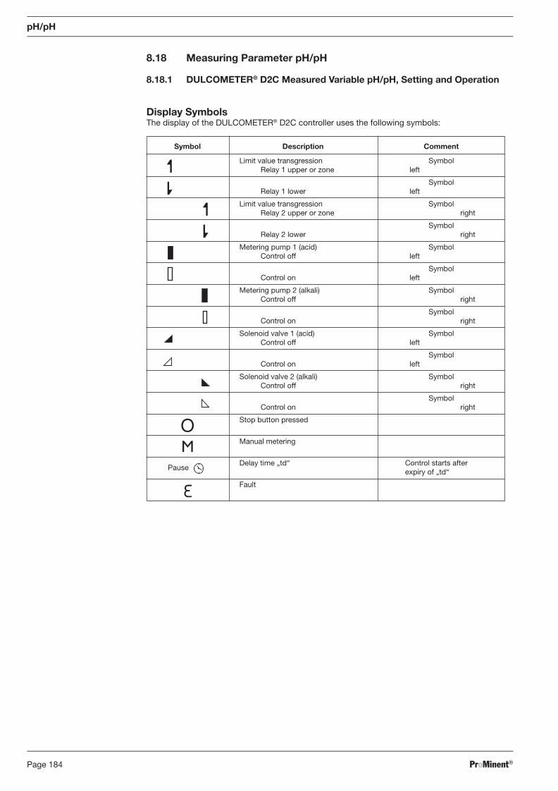
ProMinent®Page 184
8.18 Measuring Parameter pH/pH
8.18.1 DULCOMETER® D2C Measured Variable pH/pH, Setting and Operation
Display Symbols The display of the DULCOMETER® D2C controller uses the following symbols:
Symbol Description Comment
Limit value transgression Symbol Relay 1 upper or zone left
Symbol Relay 1 lower left
Limit value transgression Symbol Relay 2 upper or zone right
Symbol Relay 2 lower right
Metering pump 1 (acid) Symbol Control off left
Symbol Control on left
Metering pump 2 (alkali) Symbol Control off right
Symbol Control on right
Solenoid valve 1 (acid) Symbol Control off left
Symbol Control on left
Solenoid valve 2 (alkali) Symbol Control off right
Symbol Control on right
Stop button pressed
Manual metering
Pause
Delay time „td“ Control starts after expiry of „td“
Fault
pH/pH
BA_DR_001_02_09_GB.indd 184BA_DR_001_02_09_GB.indd 184 24.02.2009 12:24:13 Uhr24.02.2009 12:24:13 Uhr
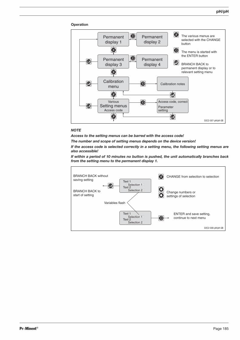
ProMinent® Page 185
pH/pH
Operation
D2C2-007-pH/pH-GB
D2C2-008-pH/pH-GB
NOTE
Access to the setting menus can be barred with the access code!
The number and scope of setting menus depends on the device version!
If the access code is selected correctly in a setting menu, the following setting menus are also accessible!
If within a period of 10 minutes no button is pushed, the unit automatically branches back from the setting menu to the permanent display 1.
BA_DR_001_02_09_GB.indd 185BA_DR_001_02_09_GB.indd 185 24.02.2009 12:24:13 Uhr24.02.2009 12:24:13 Uhr
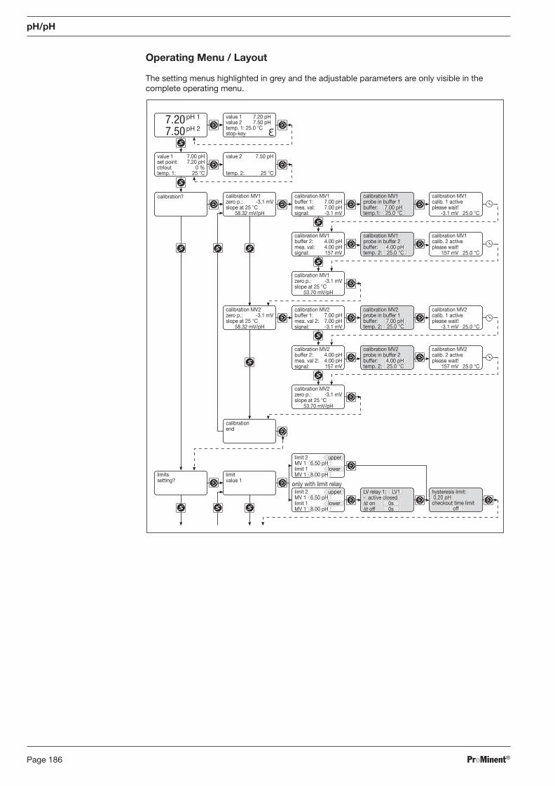
ProMinent®Page 186
pH/pH
Operating Menu / Layout
The setting menus highlighted in grey and the adjustable parameters are only visible in the complete operating menu.
calibration MV2buffer 2: 4.00 pHmea. val 2: 4.00 pHsignal: 157 mV
calibration MV2probe in buffer 2buffer: 4.00 pHtemp. 2: 25.0 °C
calibration MV2calib. 2 activeplease wait!
157 mV 25.0 °C
calibration MV2zero p.: -3.1 mVslope at 25 °C
58.32 mV/pH
calibration MV2buffer 1: 7.00 pHmea. val 2: 7.00 pHsignal: -3.1 mV
calibration MV2zero p.: -3.1 mVslope at 25 °C
53.70 mV/pH
calibration MV2probe in buffer 1buffer: 7.00 pHtemp. 2: 25.0 °C
calibration MV2calib. 1 activeplease wait!
-3.1 mV 25.0 °C
calibrationend
calibration MV1buffer 2: 4.00 pHmea. val: 4.00 pHsignal: 157 mV
calibration MV1probe in buffer 2buffer: 4.00 pHtemp. 2: 25.0 °C
calibration MV1calib. 2 activeplease wait!
157 mV 25.0 °C
value 2 7.50 pH
temp. 2: 25 °C
calibration MV1zero p.: -3.1 mVslope at 25 °C
58.32 mV/pH
calibration? calibration MV1buffer 1: 7.00 pHmea. val: 7.00 pHsignal: -3.1 mV
calibration MV1zero p.: -3.1 mVslope at 25 °C
53.70 mV/pH
value 1 7.00 pHset point 7.20 pHctrlout 0 %temp. 1: 25 °C
calibration MV1probe in buffer 1buffer: 7.00 pHtemp.1: 25.0 °C
calibration MV1calib. 1 activeplease wait!
-3.1 mV 25.0 °C
7.207.50
pH 1
pH 2
value 1 7.20 pHvalue 2 7.50 pHtemp. 1: 25.0 °Cstop-key
only with limit relayhysteresis limit: 0.20 pHcheckout time limit
off
limitvalue 1
limitssetting?
limit 2 upperMV 1 6.50 pHlimit 1 lowerMV 1 8.00 pH
limit 2 upperMV 1 6.50 pHlimit 1 lowerMV 1 8.00 pH
LV relay 1: LV1- active closedΔt on 0sΔt off 0s
BA_DR_001_02_09_GB.indd 186BA_DR_001_02_09_GB.indd 186 24.02.2009 12:24:13 Uhr24.02.2009 12:24:13 Uhr
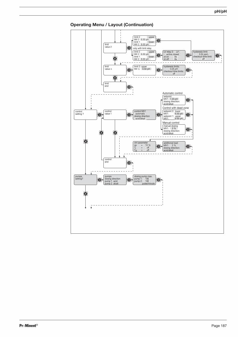
ProMinent® Page 187
pH/pH
Operating Menu / Layout (Continuation)
limitvalue 2
only with limit relayhysteresis limit:
0.04 ppmcheckout time limit:
off
limitvalue Δ
hysteresis limits:0.05 pH
checkout time limits:off
limitend
limit 2: upperMV Δ: 0.50 pH
Automatic control
Control with dead zonecontrolvalue 1
controlsetting ?
Manual control
ctrl parameterxp = 10 %Ti = offTd = off
additional loadMV1: 0 %dosing direction:acid/alkali
setpointMV1: 7.20 pHdosing direction:acid/alkali
setpoint 2: lowerMV1: 6.50 pHsetpoint 1: upperMV1: 9.00 pH
manual dosingMV1: 0 %dosing direction:acid/alkali
limit 2 upperMV 2 6.50 pHlimit 1 lowerMV 2 8.00 pH
limit 2 upperMV 2 6.50 pHlimit 1 lowerMV 2 8.00 pH
LV relay 2: LV1- active closedΔt on 0sΔt off 0s
control MV1 automaticdosing direction acid/alkali
controlend
pumpsdosing directionpump 1 acidpump 2 alcali
pumpssetting?
dosing pump max.pump 1: 180pump 2: 180
pulse/minute
BA_DR_001_02_09_GB.indd 187BA_DR_001_02_09_GB.indd 187 24.02.2009 12:24:13 Uhr24.02.2009 12:24:13 Uhr
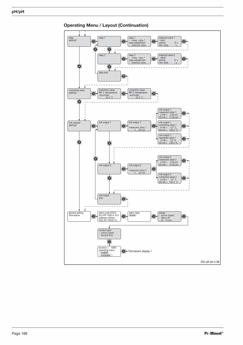
ProMinent®Page 188
correction valueMV 1: temperature automatic
25.0 °C
correction valueMV 2: temperature automatic
25.0 °C
mA outputend
relay 1relaysetting?
relay 2
relay end
correcting valuesetting?
solenoid valve 1- acidperiod 10 smin. time 1 s
solenoid valve 2- alkaliperiod 10 smin. time 1 s
relay 1- meas. value 1relay adjustment- solenoid valve
relay 2- meas. value 1relay adjustment- solenoid valve
mA output 1mA outputssetting?
mA output 1
measured value 14 ... 20 mA
mA output 1measured value 1 4 mA = 2.00 pH20 mA = 12.00 pH
mA output 1correcting value 1 4 mA = 0.0 °C20 mA = 100.0 °C
mA output 1regulated value 1 4 mA = 0.0 %20 mA = 100.0 %
mA output 2 mA output 2
measured value 24 ... 20 mA
mA output 2measured value 2 4 mA = 2.00 pH20 mA = 12.00 pH
mA output 2correcting value 2 4 mA = 0.0 °C20 mA = 100.0 °C
access c.: 5000operating menu:- english- complete
general settinginformation
ident-code D2CAW 0 PP 1000 A 10 Esoftware versionD2C-B1 FW.02.12
Permanent display 1
pause- active closed- alarm off- td: 10 min.
alarm relay active
control input- active closed- sample flow
pH/pH
D2C-pH-pH-3-GB
Operating Menu / Layout (Continuation)
BA_DR_001_02_09_GB.indd 188BA_DR_001_02_09_GB.indd 188 24.02.2009 12:24:13 Uhr24.02.2009 12:24:13 Uhr
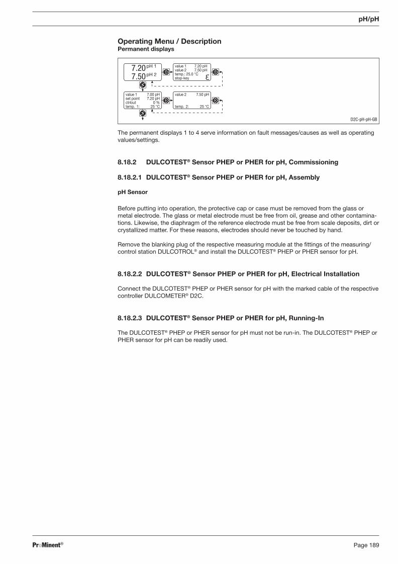
ProMinent® Page 189
pH/pH
D2C-pH-pH-GB
Operating Menu / Description Permanent displays
The permanent displays 1 to 4 serve information on fault messages/causes as well as operating values/settings.
8.18.2 DULCOTEST® Sensor PHEP or PHER for pH, Commissioning
8.18.2.1 DULCOTEST® Sensor PHEP or PHER for pH, Assembly
pH Sensor
Before putting into operation, the protective cap or case must be removed from the glass or metal electrode. The glass or metal electrode must be free from oil, grease and other contamina-tions. Likewise, the diaphragm of the reference electrode must be free from scale deposits, dirt or crystallized matter. For these reasons, electrodes should never be touched by hand.
Remove the blanking plug of the respective measuring module at the fi ttings of the measuring/control station DULCOTROL® and install the DULCOTEST® PHEP or PHER sensor for pH.
8.18.2.2 DULCOTEST® Sensor PHEP or PHER for pH, Electrical Installation
Connect the DULCOTEST® PHEP or PHER sensor for pH with the marked cable of the respective controller DULCOMETER® D2C.
8.18.2.3 DULCOTEST® Sensor PHEP or PHER for pH, Running-In
The DULCOTEST® PHEP or PHER sensor for pH must not be run-in. The DULCOTEST® PHEP or PHER sensor for pH can be readily used.
value 2 7.50 pH
temp. 2: 25 °C
value 1 7.00 pHset point 7.20 pHctrlout 0 %temp. 1: 25 °C
7.207.50
pH 1
pH 2
value 1 7.20 pHvalue 2 7.50 pHtemp.: 25.0 °Cstop-key
BA_DR_001_02_09_GB.indd 189BA_DR_001_02_09_GB.indd 189 24.02.2009 12:24:13 Uhr24.02.2009 12:24:13 Uhr
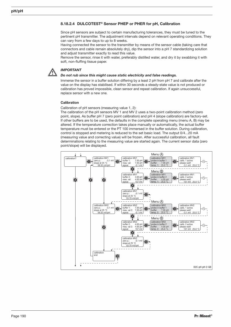
ProMinent®Page 190
calibration MV2zero p.: -3.1 mVslope at 25 °C
58.32 mV/pH
calibration MV2buffer 1: 7.00 pHmea. val 2: 7.00 pHsignal: -3.1 mV
calibration MV2calib. 1 activeplease wait!
-3.1 mV 25.0 °C
calibration MV1buffer 2: 4.00 pHmea. val: 4.00 pHsignal: 157 mV
calibration MV1calib. 2 activeplease wait!
157 mV 25.0 °C
calibration MV1zero p.: -3.1 mVslope at 25 °C
58.32 mV/pH
calibration? calibration MV1buffer 1: 7.00 pHmea. val: 7.00 pHsignal: -3.1 mV
calibration MV1zero p.: -3.1 mVslope at 25 °C
53.70 mV/pH
calibration MV1calib. 1 activeplease wait!
-3.1 mV 25.0 °C
calibration MV1probe in buffer 1buffer: 7.00 pHtemp. 1: 25.0 °C
calibration MV1probe in buffer 2buffer: 4.00 pHtemp. 1: 25.0 °C
calibration MV2probe in buffer 1buffer: 7.00 pHtemp. 2: 25.0 °C
calibration MV2buffer 2: 4.00 pHmea. val 2: 4.00 pHsignal: 157 mV
calibration MV2calib. 2 activeplease wait!
157 mV 25.0 °C
calibration MV2zero p.: -3.1 mVslope at 25 °C
53.70 mV/pH
calibrationend
calibration MV2probe in buffer 2buffer: 4.00 pHtemp. 2: 25.0 °C
8.18.2.4 DULCOTEST® Sensor PHEP or PHER for pH, Calibration
Since pH sensors are subject to certain manufacturing tolerances, they must be tuned to the pertinent pH transmitter. The adjustment intervals depend on relevant operating conditions. They can vary from a few days to up to 8 weeks.
Having connected the sensor to the transmitter by means of the sensor cable (taking care that connectors and cable remain absolutely dry), dip the sensor into a pH 7 standardizing solution and adjust transmitter exactly to read this value.
Remove the sensor, rinse it with water, preferably distilled water, and dry it by swabbing it with soft, non-fl uffi ng tissue paper.
IMPORTANT
Do not rub since this might cause static electricity and false readings.
Immerse the sensor in a buffer solution differing by a least 2 pH from pH 7 and calibrate after the value on the display has stabilised. If within 30 seconds a steady-state value is not produced or calibration has proved impossible, clean sensor and repeat calibration. If again unsuccessful, replace sensor with a new one.
Calibration
Calibration of pH sensors (measuring value 1, 2): The calibration of the pH sensors MV 1 and MV 2 uses a two-point calibration method (zero point, slope). As buffer pH 7 (zero point calibration) and pH 4 (slope calibration) are factory-set. If other buffers are to be used, the defaults in the complete operating menu (menu A, B) may be altered. If the temperature correction takes place manually or automatically, the actual buffer temperature must be entered or the PT 100 immersed in the buffer solution. During calibration, control is stopped and metering is reduced to the set basic load. The output 0/4...20 mA (measuring value and correcting value) will be frozen. After successful calibration, all fault determinations relating to the measuring value are started again. The current sensor data (zero point/slope) will be displayed.
D2C-pH-pH-2-GB
pH/pH
Menu A
Menu B
Menu A
Menu B
BA_DR_001_02_09_GB.indd 190BA_DR_001_02_09_GB.indd 190 24.02.2009 12:24:13 Uhr24.02.2009 12:24:13 Uhr
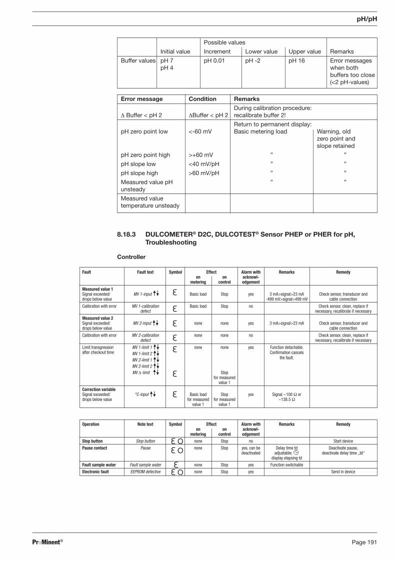
ProMinent® Page 191
Fault Fault text Symbol Effect Alarm with Remarks Remedy on on acknowl- metering control edgement
Measured value 1 Signal exceeded/ MV 1-input Basic load Stop yes 3 mA>signal>23 mA Check sensor, transducer and drops below value -499 mV>signal>499 mV cable connection
Calibration with error MV 1-calibration Basic load Stop no Check sensor, clean, replace if defect necessary, recalibrate if necessary
Measured value 2 Signal exceeded/ MV 2-input none none yes 3 mA>signal>23 mA Check sensor, transducer and drops below value cable connection
Calibration with error MV 2-calibration none none no Check sensor, clean, replace if defect necessary, recalibrate if necessary
Limit transgression MV 1-limit 1 none none yes Function detachable. after checkout time MV 1-limit 2 Confi rmation cancels
MV 2-limit 1 the fault. MV 2-limit 2 MV Δ-limit Stop for measured value 1
Correction variable Signal exceeded/ °C-input Basic load Stop yes Signal ~100 Ω or drops below value for measured for measured ~138.5 Ω value 1 value 1
pH/pH
8.18.3 DULCOMETER® D2C, DULCOTEST® Sensor PHEP or PHER for pH, Troubleshooting
Controller
Possible values
Initial value Increment Lower value Upper value Remarks
Buffer values pH 7 pH 0.01 pH -2 pH 16 Error messages pH 4 when both buffers too close (<2 pH-values)
Error message Condition Remarks
During calibration procedure: Δ Buffer < pH 2 ΔBuffer < pH 2 recalibrate buffer 2!
Return to permanent display: pH zero point low <-60 mV Basic metering load Warning, old zero point and slope retained
pH zero point high >+60 mV ” ”
pH slope low <40 mV/pH ” ”
pH slope high >60 mV/pH ” ”
Measured value pH ” ”unsteady
Measured value temperature unsteady
Operation Note text Symbol Effect Alarm with Remarks Remedy on on acknowl- metering control edgement Stop button Stop button none Stop no Start device
Pause contact Pause none Stop yes, can be Delay time td Deactivate pause, deactivated adjustable; deactivate delay time „td“ display elapsing td
Fault sample water Fault sample water none Stop yes Function switchable
Electronic fault EEPROM defective none Stop yes Send in device
BA_DR_001_02_09_GB.indd 191BA_DR_001_02_09_GB.indd 191 24.02.2009 12:24:13 Uhr24.02.2009 12:24:13 Uhr
ProMinent®Page 192
pH/pH
8.18.4 DULCOMETER® D2C Measured Variable pH/pH, DULCOTEST® Sensor PHEP or PHER for pH, Maintenance
Controller
The DULCOMETER® controller type D2C for the measured variable pH/pH is maintenance-free.
DULCOTEST® Sensor PHEP or PHER for pH
IMPORTANT
� The sensor is to be regularly serviced to avoid any excess metering caused by a sensor failure!
� Observe the valid national regulations for maintenance intervals! � Do not touch the electrodes or bring into contact with greasy substances!
Maintenance interval Monthly
Maintenance Work
The sensor should regularly (once a month) undergo a visual check and be cleaned if necessary.
If deposits on the glass electrode withstand cleaning with a soft, moistened cloth, the following cleaning agents may be used:
Kind of deposit Agent and duration of application
General deposits Non-abrasive household cleaner
Scale or metal hydroxides Diluted hydrochloric acid (approx. 0.1-3 %, 1-5 minutes)
Oil, grease Solvents, like alcohol or acetone
Biofouling Mixture of diluted hydrochloric acid and pepsin, several hours Solvents (e.g. acetone) must not be used to clean electrodes as they can demage the plastic stems.
BA_DR_001_02_09_GB.indd 192BA_DR_001_02_09_GB.indd 192 24.02.2009 12:24:13 Uhr24.02.2009 12:24:13 Uhr
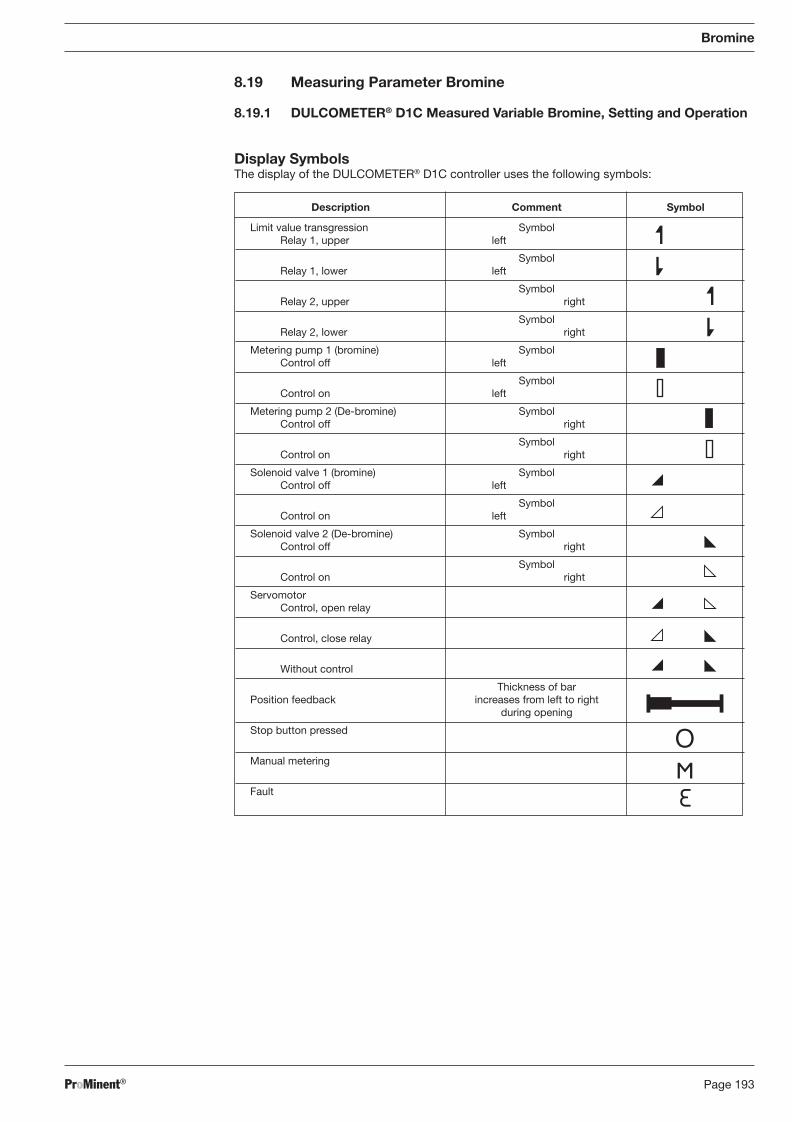
ProMinent® Page 193
8.19 Measuring Parameter Bromine 8.19.1 DULCOMETER® D1C Measured Variable Bromine, Setting and Operation
Display Symbols The display of the DULCOMETER® D1C controller uses the following symbols:
Description Comment Symbol
Limit value transgression Symbol Relay 1, upper left
Symbol Relay 1, lower left
Symbol Relay 2, upper right
Symbol Relay 2, lower right
Metering pump 1 (bromine) Symbol Control off left
Symbol Control on left
Metering pump 2 (De-bromine) Symbol Control off right
Symbol Control on right
Solenoid valve 1 (bromine) Symbol Control off left
Symbol Control on left
Solenoid valve 2 (De-bromine) Symbol Control off right
Symbol Control on right
Servomotor Control, open relay
Control, close relay
Without control
Thickness of bar Position feedback increases from left to right during opening
Stop button pressed
Manual metering
Fault
Bromine
BA_DR_001_02_09_GB.indd 193BA_DR_001_02_09_GB.indd 193 24.02.2009 12:24:13 Uhr24.02.2009 12:24:13 Uhr
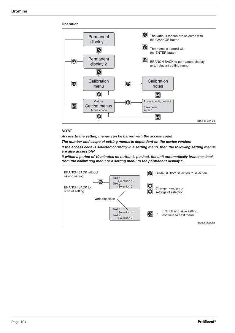
ProMinent®Page 194
Bromine
Operation
NOTE
Access to the setting menus can be barred with the access code!
The number and scope of setting menus is dependent on the device version!
If the access code is selected correctly in a setting menu, then the following setting menus are also accessible!
If within a period of 10 minutes no button is pushed, the unit automatically branches back from the calibrating menu or a setting menu to the permanent display 1.
Access code, correct
Parametersetting
Permanentdisplay 1
Permanentdisplay 2
Calibrationmenu
Various
Access codeSetting menus
The various menus are selected withthe CHANGE button
The menu is started withthe ENTER button
BRANCH BACK to permanent displayor to relevant setting menu
Calibrationnotes
D1C2-Br-007-GB
D1C2-Br-008-GB
CHANGE from selection to selection
Change numbers orsettings of selection
Variables flash
ENTER and save setting,continue to next menu
BRANCH BACK withoutsaving setting
BRANCH BACK tostart of setting
Text 1
Text 2Selection 1
Selection 2
Text 1
Text 2Selection 1
Selection 2
BA_DR_001_02_09_GB.indd 194BA_DR_001_02_09_GB.indd 194 24.02.2009 12:24:13 Uhr24.02.2009 12:24:13 Uhr
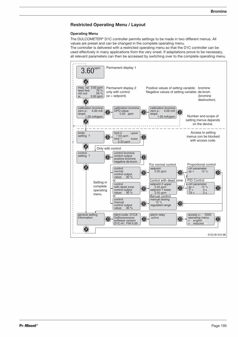
ProMinent® Page 195
Bromine
Restricted Operating Menu / Layout
Operating Menu
The DULCOMETER® D1C controller permits settings to be made in two different menus. All values are preset and can be changed in the complete operating menu.
The controller is delivered with a restricted operating menu so that the D1C controller can be used effectively in many applications from the very onset. If adaptations prove to be necessary, all relevant parameters can then be accessed by switching over to the complete operating menu.
Positive values of setting variable: bromineNegative values of setting variable: de-brom
(brominedestruction)
Permanent display 1
Permanent display 2only with control(w = setpoint)
Control with dead zone
For normal control
PID Control
Proportional control
Only with control
ppm3.60
mea. val 3.60 ppmfeed fwd: 70 %ctrl out: 59 %w: 3.00 ppm
calibration brominezero p.: 4.00 mAslope:
1.20 mA/ppm
calibration bromineDPD-value:
0.60 ppm
calibration brominezero p.: 4.00 mAslope:
1.00 mA/ppm
limitssetting ?
controlsetting ?
controlnormalcontrol outputvalue: 30 %
setpoint3.00 ppm
ctrl parameterxp = 10 %
setpoint 2 upper3.00 ppm
setpoint 1 lower3.00 ppm
controlmanualcontrol outputvalue: 30 %
manual dosing15 %
regulated range
general settinginformation
ident-code: D1CADxBxxxxxxxxxxsoftware versionD1C-A1 FW-5.00
alarm relay active
access c.: 5000operating menu:= english= reduced
or
or
controlwith dead zonecontrol outputvalue: 30 %
Setting incompleteoperatingmenu
limit 2 upper7.50 ppm
limit 1 lower0.50 ppm
ctrl parameterxp = 10 %Ti = 0 sTd = 0 s
Manual control
Number and scope ofsetting menus depends
on the device.
Access to settingmenus con be blocked
with access code.
control brominecontrol outputpositive brominenegative de-brom
D1C2-Br-010-GB
BA_DR_001_02_09_GB.indd 195BA_DR_001_02_09_GB.indd 195 24.02.2009 12:24:14 Uhr24.02.2009 12:24:14 Uhr
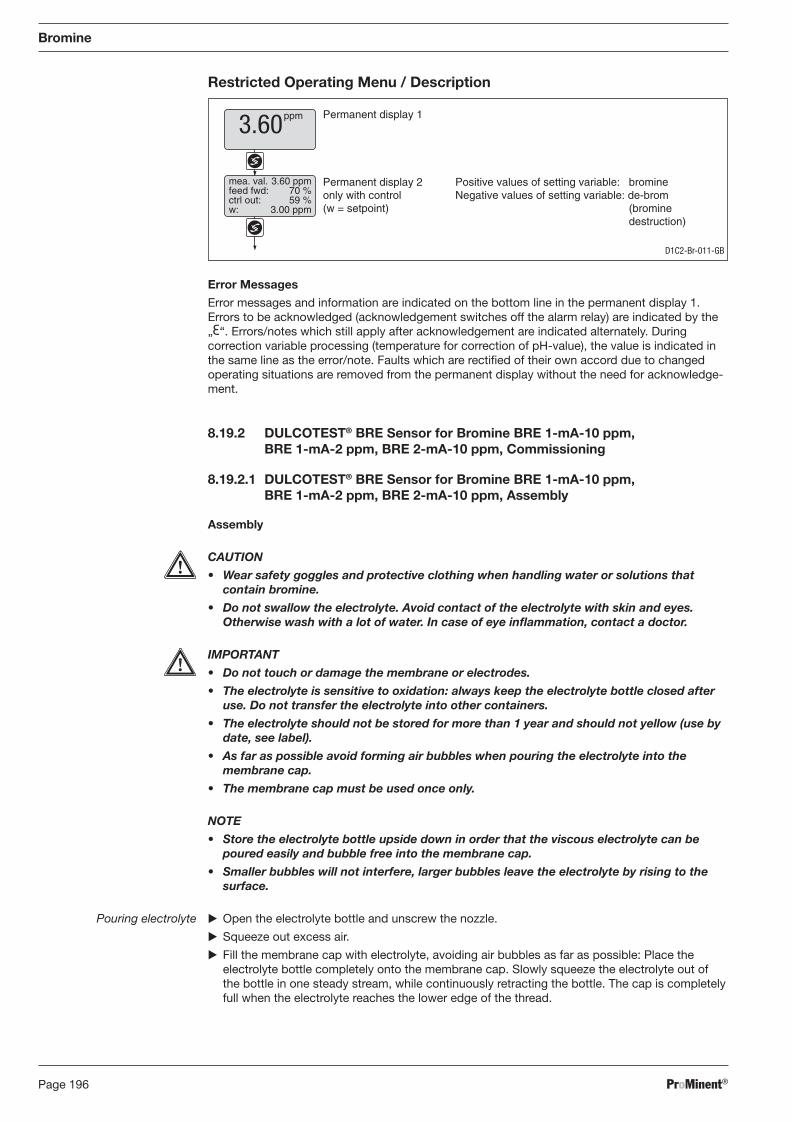
ProMinent®Page 196
Bromine
Restricted Operating Menu / Description
Error Messages
Error messages and information are indicated on the bottom line in the permanent display 1. Errors to be acknowledged (acknowledgement switches off the alarm relay) are indicated by the „ “. Errors/notes which still apply after acknowledgement are indicated alternately. During correction variable processing (temperature for correction of pH-value), the value is indicated in the same line as the error/note. Faults which are rectifi ed of their own accord due to changed operating situations are removed from the permanent display without the need for acknowledge-ment.
8.19.2 DULCOTEST® BRE Sensor for Bromine BRE 1-mA-10 ppm, BRE 1-mA-2 ppm, BRE 2-mA-10 ppm, Commissioning
8.19.2.1 DULCOTEST® BRE Sensor for Bromine BRE 1-mA-10 ppm, BRE 1-mA-2 ppm, BRE 2-mA-10 ppm, Assembly
Assembly
CAUTION
• Wear safety goggles and protective clothing when handling water or solutions that contain bromine.
• Do not swallow the electrolyte. Avoid contact of the electrolyte with skin and eyes. Otherwise wash with a lot of water. In case of eye infl ammation, contact a doctor.
IMPORTANT
• Do not touch or damage the membrane or electrodes.
• The electrolyte is sensitive to oxidation: always keep the electrolyte bottle closed after use. Do not transfer the electrolyte into other containers.
• The electrolyte should not be stored for more than 1 year and should not yellow (use by date, see label).
• As far as possible avoid forming air bubbles when pouring the electrolyte into the membrane cap.
• The membrane cap must be used once only.
NOTE
• Store the electrolyte bottle upside down in order that the viscous electrolyte can be poured easily and bubble free into the membrane cap.
• Smaller bubbles will not interfere, larger bubbles leave the electrolyte by rising to the surface.
Pouring electrolyte � Open the electrolyte bottle and unscrew the nozzle.
� Squeeze out excess air.
� Fill the membrane cap with electrolyte, avoiding air bubbles as far as possible: Place the electrolyte bottle completely onto the membrane cap. Slowly squeeze the electrolyte out of the bottle in one steady stream, while continuously retracting the bottle. The cap is completely full when the electrolyte reaches the lower edge of the thread.
Permanent display 1
Permanent display 2only with control(w = setpoint)
ppm3.60
mea. val. 3.60 ppmfeed fwd: 70 %ctrl out: 59 %w: 3.00 ppm
Positive values of setting variable: bromineNegative values of setting variable: de-brom
(brominedestruction)
D1C2-Br-011-GB
BA_DR_001_02_09_GB.indd 196BA_DR_001_02_09_GB.indd 196 24.02.2009 12:24:14 Uhr24.02.2009 12:24:14 Uhr
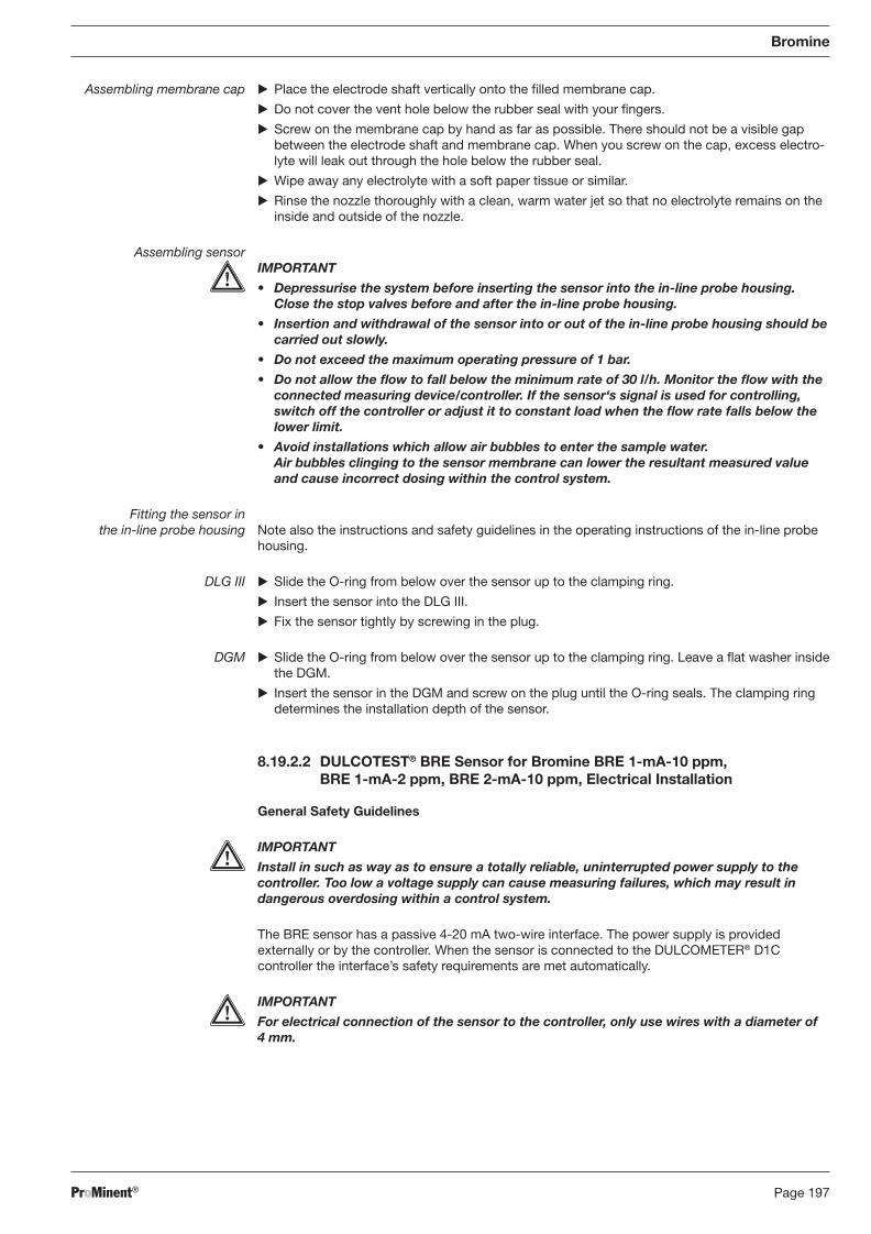
ProMinent® Page 197
Bromine
Assembling membrane cap � Place the electrode shaft vertically onto the fi lled membrane cap.
� Do not cover the vent hole below the rubber seal with your fi ngers.
� Screw on the membrane cap by hand as far as possible. There should not be a visible gap between the electrode shaft and membrane cap. When you screw on the cap, excess electro-lyte will leak out through the hole below the rubber seal.
� Wipe away any electrolyte with a soft paper tissue or similar.
� Rinse the nozzle thoroughly with a clean, warm water jet so that no electrolyte remains on the inside and outside of the nozzle.
Assembling sensor IMPORTANT
• Depressurise the system before inserting the sensor into the in-line probe housing. Close the stop valves before and after the in-line probe housing.
• Insertion and withdrawal of the sensor into or out of the in-line probe housing should be carried out slowly.
• Do not exceed the maximum operating pressure of 1 bar.
• Do not allow the fl ow to fall below the minimum rate of 30 l/h. Monitor the fl ow with the connected measuring device/controller. If the sensor‘s signal is used for controlling, switch off the controller or adjust it to constant load when the fl ow rate falls below the lower limit.
• Avoid installations which allow air bubbles to enter the sample water. Air bubbles clinging to the sensor membrane can lower the resultant measured value and cause incorrect dosing within the control system.
Fitting the sensor in the in-line probe housing Note also the instructions and safety guidelines in the operating instructions of the in-line probe
housing.
DLG III � Slide the O-ring from below over the sensor up to the clamping ring.
� Insert the sensor into the DLG III.
� Fix the sensor tightly by screwing in the plug.
DGM � Slide the O-ring from below over the sensor up to the clamping ring. Leave a fl at washer inside the DGM.
� Insert the sensor in the DGM and screw on the plug until the O-ring seals. The clamping ring determines the installation depth of the sensor.
8.19.2.2 DULCOTEST® BRE Sensor for Bromine BRE 1-mA-10 ppm, BRE 1-mA-2 ppm, BRE 2-mA-10 ppm, Electrical Installation
General Safety Guidelines
IMPORTANT
Install in such as way as to ensure a totally reliable, uninterrupted power supply to the controller. Too low a voltage supply can cause measuring failures, which may result in dangerous overdosing within a control system.
The BRE sensor has a passive 4-20 mA two-wire interface. The power supply is provided externally or by the controller. When the sensor is connected to the DULCOMETER® D1C controller the interface’s safety require ments are met automatically.
IMPORTANT
For electrical connection of the sensor to the controller, only use wires with a diameter of 4 mm.
BA_DR_001_02_09_GB.indd 197BA_DR_001_02_09_GB.indd 197 24.02.2009 12:24:14 Uhr24.02.2009 12:24:14 Uhr
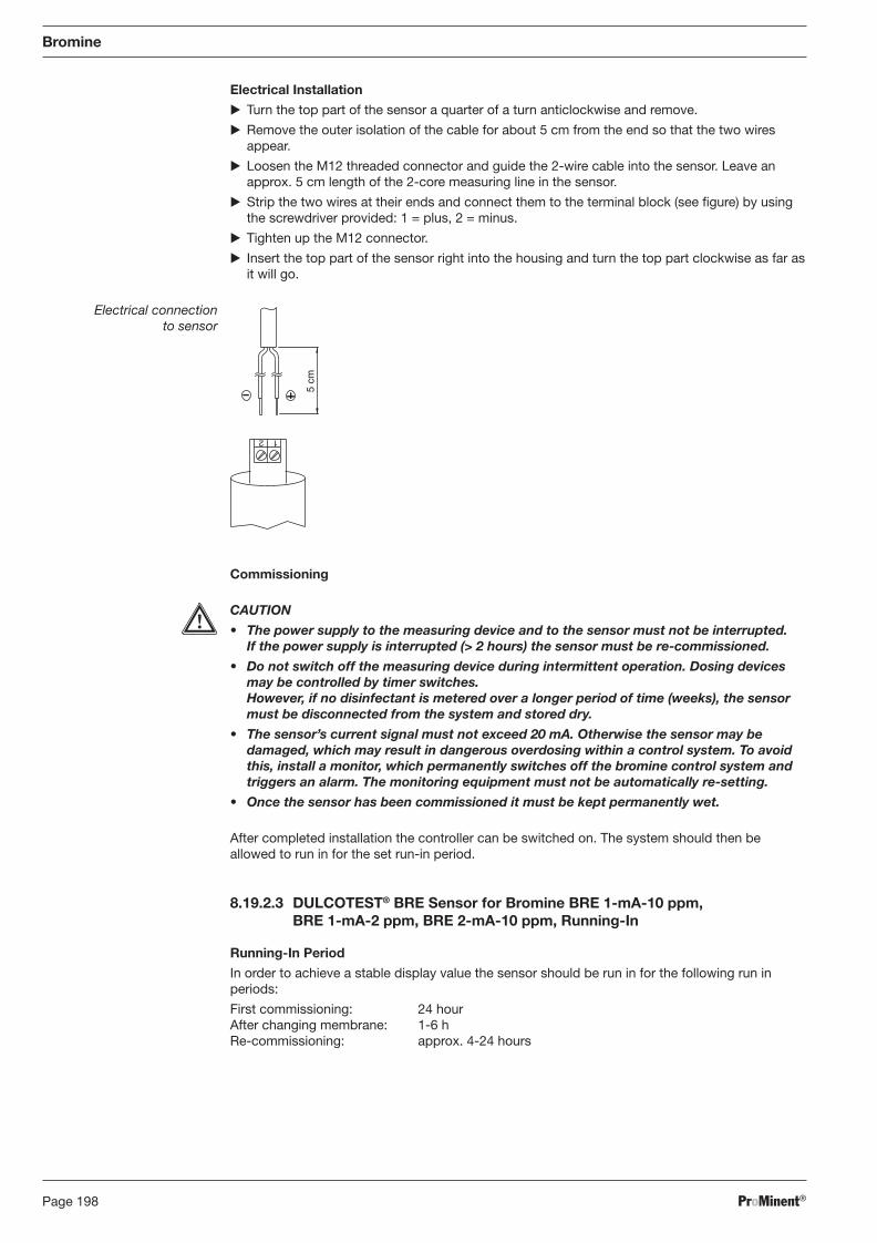
ProMinent®Page 198
Bromine
Electrical Installation
� Turn the top part of the sensor a quarter of a turn anticlockwise and remove.
� Remove the outer isolation of the cable for about 5 cm from the end so that the two wires appear.
� Loosen the M12 threaded connector and guide the 2-wire cable into the sensor. Leave an approx. 5 cm length of the 2-core measuring line in the sensor.
� Strip the two wires at their ends and connect them to the terminal block (see fi gure) by using the screwdriver provided: 1 = plus, 2 = minus.
� Tighten up the M12 connector.
� Insert the top part of the sensor right into the housing and turn the top part clockwise as far as it will go.
Electrical connection to sensor
1 2
5 cm
Commissioning
CAUTION
• The power supply to the measuring device and to the sensor must not be interrupted. If the power supply is interrupted (> 2 hours) the sensor must be re-commis sioned.
• Do not switch off the measuring device during intermittent operation. Dosing devices may be controlled by timer switches. However, if no disinfectant is metered over a longer period of time (weeks), the sensor must be disconnected from the system and stored dry.
• The sensor’s current signal must not exceed 20 mA. Otherwise the sensor may be damaged, which may result in dangerous overdosing within a control system. To avoid this, install a monitor, which permanently switches off the bromine control system and triggers an alarm. The monitoring equipment must not be automatically re-setting.
• Once the sensor has been commissioned it must be kept permanently wet.
After completed installation the controller can be switched on. The system should then be allowed to run in for the set run-in period.
8.19.2.3 DULCOTEST® BRE Sensor for Bromine BRE 1-mA-10 ppm, BRE 1-mA-2 ppm, BRE 2-mA-10 ppm, Running-In
Running-In Period
In order to achieve a stable display value the sensor should be run in for the following run in periods:
First commissioning: 24 hour After changing membrane: 1-6 h Re-commissioning: approx. 4-24 hours
BA_DR_001_02_09_GB.indd 198BA_DR_001_02_09_GB.indd 198 24.02.2009 12:24:14 Uhr24.02.2009 12:24:14 Uhr
ProMinent® Page 199
Bromine
8.19.2.4 DULCOTEST® BRE Sensor for Bromine BRE 1-mA-10 ppm, BRE 1-mA-2 ppm, BRE 2-mA-10 ppm, Calibration
Calibration
IMPORTANT
The specifi ed calibration method depending on the type of bromination agent used must be observed.
CAUTION
• Carry out a slope test every time the membrane or electrolyte is changed.
• Avoid air-bubbles in the sample fl ow. They can attach at the sensor membrane, which may cause too low measured values. Within a control system this may lead to dangerous over dosing.
• For proper function of the sensor, the slope test has to be repeated regularly.
• If bromine is measured as chlorine with a DPD set, make sure that you convert the values into bromine.
• If installing the sensor outside Germany, please comply with the local regulations for calibration intervals.
Preconditions The sensor reading is stable (no drifts or unsteady values for at least 5 minutes). This is normally fulfi lled, when
• The system has been allowed to run-in for the specifi ed period
• The fl ow through the in-line probe housing is constant and corresponds with the technical data
• The sample medium and the sensor are at the same temperature
• The pH value is constant and within the admissible range (pH 6.5 - 9.5)
Zero Point Calibration
Zero point calibration is necessary only when the sensor is used at the lower limit of the measuring range.
� Remove the sensor from the DLG III or DGM in-line probe housing (see DLG III, DGM operating instructions).
� Immerse the sensor in a container with clean water, free of chlorine and bromine.
� Stir by using the sensor, until the measured value remains stable.
� Adjust the controller (DULCOMETER® D1C, Bromine) to zero, according to it‘s operating instructions manual (DULCOMETER® D1C, Bromine Operating Instructions: Chapter 8, complete operating menu, settings menu “Calibrating bromine zero point”).
� Reinstall the sensor into the in-line-probe-housing (DGM, DLG III).
Slope Test
� Insert the sensor into the DLG III or DGM in-line probe housing, if not already done.
� Take a water sample for DPD-measurement. Sampling location has to be close to the installed sensor. Recommendation: use the sampling tap in the case of the DGM in-line probe housing
� Determine the bromine content with a suitable DPD-Method ( e.g. DPD). DPD 4 is especially recommended, when organically bound bromine like BDCMH (1-Br, 3-Cl-5,5 dimethylehy-dantoine) is present. In case of high and constant ratios of free bromine (HOBr), the DPD 1 method is also suitable.
BA_DR_001_02_09_GB.indd 199BA_DR_001_02_09_GB.indd 199 24.02.2009 12:24:14 Uhr24.02.2009 12:24:14 Uhr
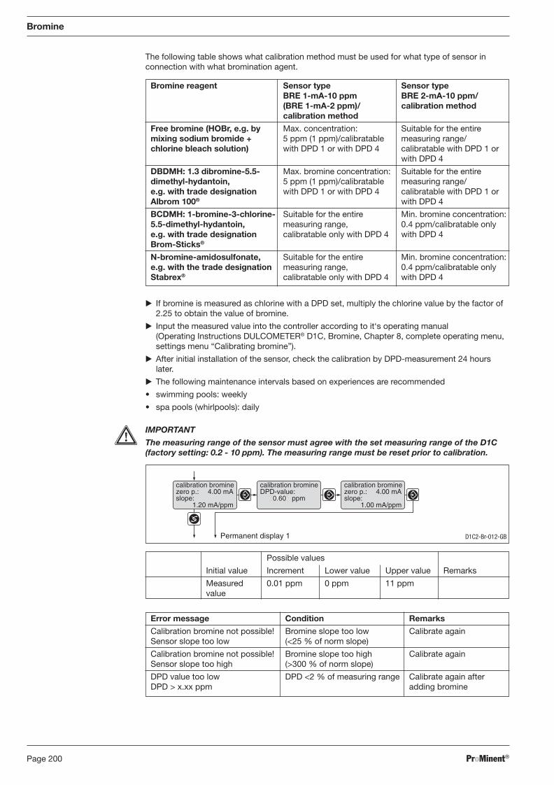
ProMinent®Page 200
The following table shows what calibration method must be used for what type of sensor in connection with what bromination agent.
Bromine
� If bromine is measured as chlorine with a DPD set, multiply the chlorine value by the factor of 2.25 to obtain the value of bromine.
� Input the measured value into the controller according to it‘s operating manual (Operating Instructions DULCOMETER® D1C, Bromine, Chapter 8, complete operating menu, settings menu “Calibrating bromine”).
� After initial installation of the sensor, check the calibration by DPD-measurement 24 hours later.
� The following maintenance intervals based on experiences are recommended
• swimming pools: weekly
• spa pools (whirlpools): daily
IMPORTANT
The measuring range of the sensor must agree with the set measuring range of the D1C (factory setting: 0.2 - 10 ppm). The measuring range must be reset prior to calibration.
Bromine reagent Sensor type Sensor type BRE 1-mA-10 ppm BRE 2-mA-10 ppm/ (BRE 1-mA-2 ppm)/ calibration method calibration method
Free bromine (HOBr, e.g. by Max. concentration: Suitable for the entire mixing sodium bromide + 5 ppm (1 ppm)/calibratable measuring range/chlorine bleach solution) with DPD 1 or with DPD 4 calibratable with DPD 1 or with DPD 4
DBDMH: 1.3 dibromine-5.5- Max. bromine concentration: Suitable for the entire dimethyl-hydantoin, 5 ppm (1 ppm)/calibratable measuring range/ e.g. with trade designation with DPD 1 or with DPD 4 calibratable with DPD 1 or Albrom 100® with DPD 4
BCDMH: 1-bromine-3-chlorine- Suitable for the entire Min. bromine concentration: 5.5-dimethyl-hydantoin, measuring range, 0.4 ppm/calibratable only e.g. with trade designation calibratable only with DPD 4 with DPD 4 Brom-Sticks®
N-bromine-amidosulfonate, Suitable for the entire Min. bromine concentration:e.g. with the trade designation measuring range, 0.4 ppm/calibratable only Stabrex® calibratable only with DPD 4 with DPD 4
Possible values
Initial value Increment Lower value Upper value Remarks
Measured 0.01 ppm 0 ppm 11 ppm value
Permanent display 1
calibration brominezero p.: 4.00 mAslope:
1.20 mA/ppm
calibration bromineDPD-value:
0.60 ppm
calibration brominezero p.: 4.00 mAslope:
1.00 mA/ppm
D1C2-Br-012-GB
Error message Condition Remarks
Calibration bromine not possible! Bromine slope too low Calibrate again Sensor slope too low (<25 % of norm slope)
Calibration bromine not possible! Bromine slope too high Calibrate again Sensor slope too high (>300 % of norm slope)
DPD value too low DPD <2 % of measuring range Calibrate again after DPD > x.xx ppm adding bromine
BA_DR_001_02_09_GB.indd 200BA_DR_001_02_09_GB.indd 200 24.02.2009 12:24:14 Uhr24.02.2009 12:24:14 Uhr
ProMinent® Page 201
Bromine
Calibration of the Bromine Sensor
During the calibration the DULCOMETER® D1C switches the control outputs to “0”. Exception: where a basic load or a manual control variable has been entered it is retained throughout the calibration.
The standard mA signal outputs (measured value or correction value) are frozen. The frozen measured value from the start of the calibration is suggested as the DPD value. The DPD values are variable (arrow keys). Calibration is possible only when the DPD value is ≥ 2 % of the measurement range.
If the calibration is successful all fault-fi nding operations relating to the measured value start afresh.
In the limited-access operating menu: the DULCOMETER® D1C saves the detected slope values.
In the full operating menu: the DULCOMETER® D1C saves the detected slope and zero point values.
The zero point calibration must be carried out under real conditions in bromide-free water. It is normally required only for the measurement range 0-0.5 ppm when measuring at the lower measurement range limit.
BA_DR_001_02_09_GB.indd 201BA_DR_001_02_09_GB.indd 201 24.02.2009 12:24:14 Uhr24.02.2009 12:24:14 Uhr
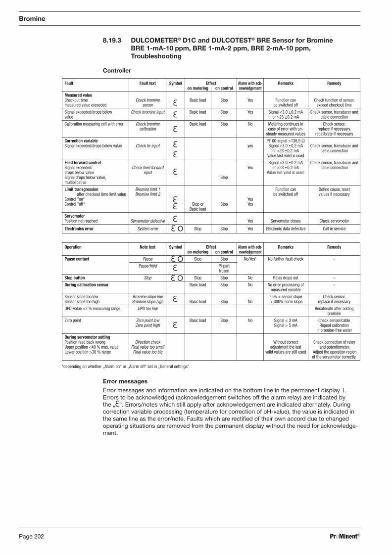
ProMinent®Page 202
Fault Fault text Symbol Effect Alarm with ack- Remarks Remedy on metering on control nowledgement
Measured value Checkout time Check bromine Basic load Stop Yes Function can Check function of sensor, measured value exceeded sensor be switched off exceed checkout time
Signal exceeded/drops below Check bromine input Basic load Stop Yes Signal <3.0 ±0.2 mA Check sensor, transducer and value or >23 ±0.2 mA cable connection
Calibration measuring cell with error Check bromine Basic load Stop No Metering continues in Check sensor, calibration case of error with un- replace if necessary, steady measured values recalibrate if necessary
Correction variable Pt100-signal >138,5 Ω Signal exceeded/drops below value Check te-input yes Signal <3,0 ±0,2 mA Check sensor, transducer and or >23 ±0,2 mA cable connection Value last valid is used
Feed forward control Signal <3.0 ±0.2 mA Check sensor, transducer and Signal exceeded/ Check feed forward Yes or >23 ±0.2 mA cable connection drops below value input Value last valid is used. Signal drops below value, Stop multiplicative
Limit transgression Bromine limit 1 Function can Defi ne cause, reset after checkout time limit value Bromine limit 2 be switched off values if necessary Control ”on“ Yes Control ”off“ Stop or Stop Yes Basic load
Servomotor Position not reached Servomotor defective Yes Servomotor closes Check servomotor
Electronics error System error Stop Stop Yes Elektronic data defective Call in service
Bromine
8.19.3 DULCOMETER® D1C and DULCOTEST® BRE Sensor for Bromine BRE 1-mA-10 ppm, BRE 1-mA-2 ppm, BRE 2-mA-10 ppm, Troubleshooting
Controller
Operation Note text Symbol Effect Alarm with ack- Remarks Remedy on metering on control nowledgement
Pause contact Pause Stop Stop No/Yes* No further fault check –
Pause/Hold PI-part frozen
Stop button Stop Stop Stop No Relay drops out –
During calibration sensor Basic load Stop No No error processing of – measured variable
Sensor slope too low Bromine slope low 25% > sensor slope Check sensor, Sensor slope too high Bromine slope high Basic load Stop No > 300% norm slope replace if necessary
DPD-value <2 % measuring range DPD too low Recalibrate after adding bromine
Zero point Zero point low Basic load Stop No Signal < 3 mA Check sensor/cable Zero point high Signal > 5 mA Repeat calibration in bromine-free water
During servomotor setting Position feed back wrong Direction check Without correct Check connection of relay Upper position <40 % max. value Final value too small adjustment the last and potentiometer. Lower position >30 % range Final value too big valid values are still used Adjust the operation region of the servomotor correctly.
*depending on whether „Alarm on“ or „Alarm off“ set in „General settings“
Error messages
Error messages and information are indicated on the bottom line in the permanent display 1. Errors to be acknowledged (acknowledgement switches off the alarm relay) are indicated by the „ “. Errors/notes which still apply after acknowledgement are indicated alternately. During correction variable processing (temperature for correction of pH-value), the value is indicated in the same line as the error/note. Faults which are rectifi ed of their own accord due to changed operating situations are removed from the permanent display without the need for acknowledge-ment.
BA_DR_001_02_09_GB.indd 202BA_DR_001_02_09_GB.indd 202 24.02.2009 12:24:14 Uhr24.02.2009 12:24:14 Uhr
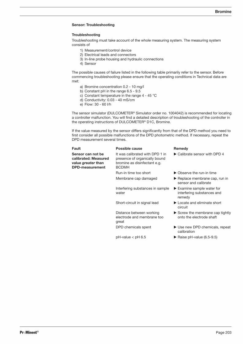
ProMinent® Page 203
Bromine
Sensor: Troubleshooting
Troubleshooting
Troubleshooting must take account of the whole measuring system. The measuring system consists of
1) Measurement/control device 2) Electrical leads and connectors 3) In-line probe housing and hydraulic connections 4) Sensor
The possible causes of failure listed in the following table primarily refer to the sensor. Before commencing troubleshooting please ensure that the operating conditions in Technical data are met:
a) Bromine concentration 0.2 - 10 mg/l b) Constant pH in the range 6.5 - 9.5 c) Constant temperature in the range 4 - 45 °C d) Conductivity: 0.03 - 40 mS/cm e) Flow: 30 - 60 l/h
The sensor simulator (DULCOMETER® Simulator order no. 1004042) is recommended for locating a controller malfunction. You will fi nd a detailed description of troubleshooting of the controller in the operating instructions of DULCOMETER® D1C, Bromine.
If the value measured by the sensor differs signifi cantly from that of the DPD method you need to fi rst consider all possible malfunctions of the DPD photometric method. If necessary, repeat the DPD measurement several times.
Fault
Sensor can not be calibrated: Measured value greater than DPD-measurement
Possible cause
It was calibrated with DPD 1 in presence of organically bound bromine as disinfectant e.g. BCDMH
Run-in time too short
Membrane cap damaged
Interfering substances in sample water
Short-circuit in signal lead
Distance between working electrode and membrane too great
DPD chemicals spent
pH-value < pH 6.5
Remedy
� Calibrate sensor with DPD 4
� Observe the run-in time
� Replace membrane cap, run in sensor and calibrate
� Examine sample water for interfering substances and remedy
� Locate and eliminate short circuit
� Screw the membrane cap tightly onto the electrode shaft
� Use new DPD chemicals, repeat calibration
� Raise pH-value (6.5-9.5)
BA_DR_001_02_09_GB.indd 203BA_DR_001_02_09_GB.indd 203 24.02.2009 12:24:14 Uhr24.02.2009 12:24:14 Uhr
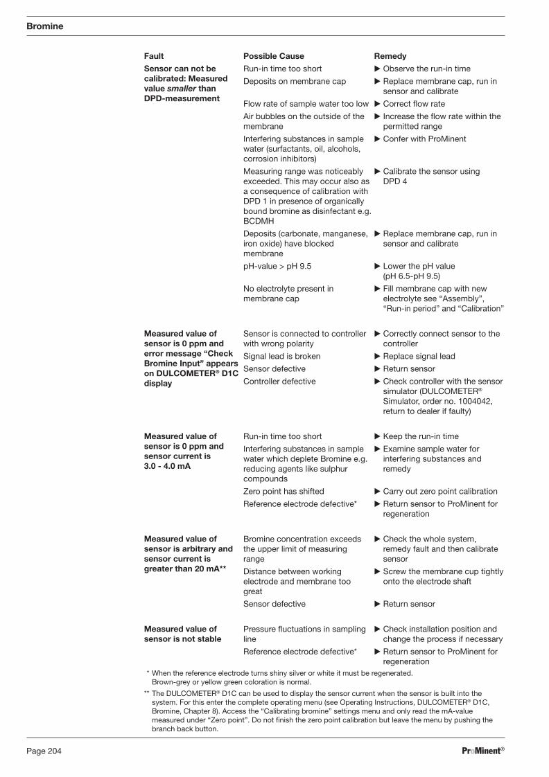
ProMinent®Page 204
Bromine
� Observe the run-in time
� Replace membrane cap, run in sensor and calibrate
� Correct fl ow rate
� Increase the fl ow rate within the permitted range
� Confer with ProMinent
� Calibrate the sensor using DPD 4
� Replace membrane cap, run in sensor and calibrate
� Lower the pH value (pH 6.5-pH 9.5)
� Fill membrane cap with new electrolyte see “Assembly”, “Run-in period” and “Calibration”
� Correctly connect sensor to the controller
� Replace signal lead
� Return sensor
� Check controller with the sensor simulator (DULCOMETER® Simulator, order no. 1004042, return to dealer if faulty)
� Keep the run-in time
� Examine sample water for interfering substances and remedy
� Carry out zero point calibration
� Return sensor to ProMinent for regeneration
� Check the whole system, remedy fault and then calibrate sensor
� Screw the membrane cup tightly onto the electrode shaft
� Return sensor
� Check installation position and change the process if necessary
� Return sensor to ProMinent for regeneration
Fault Possible Cause Remedy
Sensor can not be calibrated: Measured value smaller than DPD-measurement
Measured value of sensor is 0 ppm and error message “Check Bromine Input” appears on DULCOMETER® D1C display
Measured value of sensor is 0 ppm and sensor current is 3.0 - 4.0 mA
Measured value of sensor is arbitrary and sensor current is greater than 20 mA**
Measured value of sensor is not stable
Run-in time too short
Deposits on membrane cap
Flow rate of sample water too low
Air bubbles on the outside of the membrane
Interfering substances in sample water (surfactants, oil, alcohols, corrosion inhibitors)
Measuring range was noticeably exceeded. This may occur also as a consequence of calibration with DPD 1 in presence of organically bound bromine as disinfectant e.g. BCDMH
Deposits (carbonate, manganese, iron oxide) have blocked membrane
pH-value > pH 9.5
No electrolyte present in membrane cap
Sensor is connected to controller with wrong polarity
Signal lead is broken
Sensor defective
Controller defective
Run-in time too short
Interfering substances in sample water which deplete Bromine e.g. reducing agents like sulphur compounds
Zero point has shifted
Reference electrode defective*
Bromine concentration exceeds the upper limit of measuring range
Distance between working electrode and membrane too great
Sensor defective
Pressure fl uctuations in sampling line
Reference electrode defective*
* When the reference electrode turns shiny silver or white it must be regenerated. Brown-grey or yellow green coloration is normal.
** The DULCOMETER® D1C can be used to display the sensor current when the sensor is built into the system. For this enter the complete operating menu (see Operating Instructions, DULCOMETER® D1C, Bromine, Chapter 8). Access the “Calibrating bromine” settings menu and only read the mA-value measured under “Zero point”. Do not fi nish the zero point calibration but leave the menu by pushing the branch back button.
BA_DR_001_02_09_GB.indd 204BA_DR_001_02_09_GB.indd 204 24.02.2009 12:24:14 Uhr24.02.2009 12:24:14 Uhr
ProMinent® Page 205
Bromine
8.19.4 DULCOMETER® D1C Measured Variable Bromine and DULCOTEST® BRE Sensor for Bromine BRE 1-mA-10 ppm, BRE 1-mA-2 ppm, BRE 2-mA-10 ppm, Maintenance
Controller
The DULCOMETER® controller type D1C for the measured variable bromine is maintenance-free.
Sensor
IMPORTANT
� Service the sensor regularly to avoid overdosing within a control system, due to in-correct measured value.
� Observe the current national regulations for maintenance intervals.
� Do not touch the electrodes or allow them to come into contact with greasy substances.
� Never attempt to clean the membrane with acid/alkaline solutions, cleaning reagents or mechanical aids (brushes or similar).
Maintenance intervals based on experience are
• swimming pools: weekly
• spa pools (whirlpools): daily
Maintenance Work
� Check the sensor regularly for dirt, algae and air bubbles. As far as possible, avoid contamina-tion of the membrane with solid particles, deposits etc. Eliminate air bubbles by increasing the fl ow rate.
� Check the sensor’s reading on the controller regularly, using an appropriate instrument for measuring bromine (e.g. DPD). If using BCDMH: DPD 4, DPD 1 in case of DBDMH: DPD 1
� If necessary, recalibrate the sensor
� If calibration cannot be carried out properly, the membrane cap must be replaced and calibration must be repeated.
BA_DR_001_02_09_GB.indd 205BA_DR_001_02_09_GB.indd 205 24.02.2009 12:24:14 Uhr24.02.2009 12:24:14 Uhr
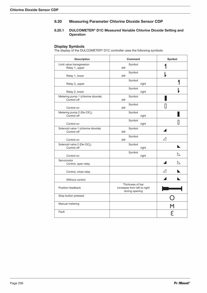
ProMinent®Page 206
Description Comment Symbol
Limit value transgression Symbol Relay 1, upper left
Symbol Relay 1, lower left
Symbol Relay 2, upper right
Symbol Relay 2, lower right
Metering pump 1 (chlorine dioxide) Symbol Control off left
Symbol Control on left
Metering pump 2 (De-ClO2) Symbol Control off right
Symbol Control on right
Solenoid valve 1 (chlorine dioxide) Symbol Control off left
Symbol Control on left
Solenoid valve 2 (De-ClO2) Symbol Control off right
Symbol Control on right
Servomotor Control, open relay
Control, close relay
Without control
Thickness of bar Position feedback increases from left to right during opening
Stop button pressed
Manual metering
Fault
Chlorine Dioxide Sensor CDP
8.20 Measuring Parameter Chlorine Dioxide Sensor CDP
8.20.1 DULCOMETER® D1C Measured Variable Chlorine Dioxide Setting and Operation
Display Symbols The display of the DULCOMETER® D1C controller uses the following symbols:
BA_DR_001_02_09_GB.indd 206BA_DR_001_02_09_GB.indd 206 24.02.2009 12:24:14 Uhr24.02.2009 12:24:14 Uhr
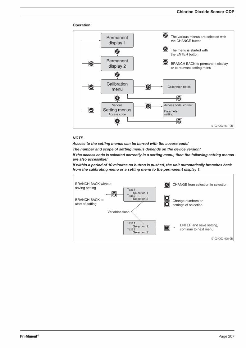
ProMinent® Page 207
Chlorine Dioxide Sensor CDP
Operation
NOTE
Access to the setting menus can be barred with the access code!
The number and scope of setting menus depends on the device version!
If the access code is selected correctly in a setting menu, then the following setting menus are also accessible!
If within a period of 10 minutes no button is pushed, the unit automatically branches back from the calibrating menu or a setting menu to the permanent display 1.
Access code, correct
Parametersetting
Calibration notes
Permanentdisplay 1
Permanentdisplay 2
Calibrationmenu
Various
Access codeSetting menus
The various menus are selected withthe CHANGE button
The menu is started withthe ENTER button
BRANCH BACK to permanent displayor to relevant setting menu
CHANGE from selection to selection
Change numbers orsettings of selection
Variables flash
ENTER and save setting,continue to next menu
BRANCH BACK withoutsaving setting
BRANCH BACK tostart of setting
Text 1
Text 2Selection 1
Selection 2
Text 1
Text 2Selection 1
Selection 2
D1C2-CIO2-007-GB
D1C2-CIO2-008-GB
BA_DR_001_02_09_GB.indd 207BA_DR_001_02_09_GB.indd 207 24.02.2009 12:24:14 Uhr24.02.2009 12:24:14 Uhr
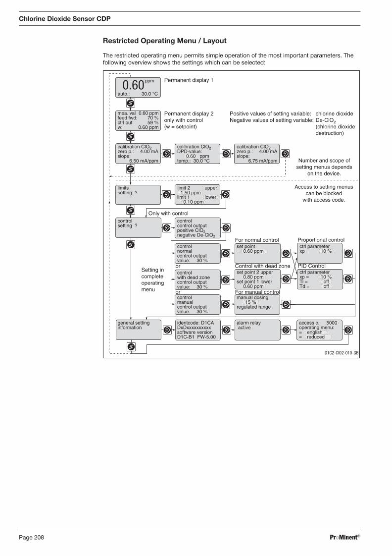
ProMinent®Page 208
Chlorine Dioxide Sensor CDP
Restricted Operating Menu / Layout
The restricted operating menu permits simple operation of the most important parameters. The following overview shows the settings which can be selected:
Positive values of setting variable: chlorine dioxideNegative values of setting variable: De-ClO2
(chlorine dioxidedestruction)
auto.: 30.0 °C
Permanent display 1
Permanent display 2only with control(w = setpoint)
Control with dead zone
For normal control
PID Control
Proportional control
Only with control
ppm0.60
mea. val 0.60 ppmfeed fwd: 70 %ctrl out: 59 %w: 0.60 ppm
calibration ClO2zero p.: 4.00 mAslope:
6.50 mA/ppm
calibration ClO2DPD-value:
0.60 ppmtemp.: 30.0 °C
calibration ClO2zero p.: 4.00 mAslope:
6.75 mA/ppm
limitssetting ?
controlsetting ?
controlnormalcontrol outputvalue: 30 %
set point0.60 ppm
ctrl parameterxp = 10 %
controlwith dead zonecontrol outputvalue: 30 %
set point 2 upper0.80 ppm
set point 1 lower0.60 ppm
controlmanualcontrol outputvalue: 30 %
manual dosing15 %
regulated range
general settinginformation
identcode: D1CADxDxxxxxxxxxxsoftware versionD1C-B1 FW-5.00
alarm relay active
access c.: 5000operating menu:= english= reduced
Access to setting menuscan be blocked
with access code.
Setting incompleteoperatingmenu For manual control
or
or
ctrl parameterxp = 10 %Ti = offTd = off
limit 1 lower0.10 ppm
limit 2 upper1.50 ppm
Number and scope ofsetting menus depends
on the device.
controlcontrol outputpositive ClO2negative De-ClO2
D1C2-CIO2-010-GB
BA_DR_001_02_09_GB.indd 208BA_DR_001_02_09_GB.indd 208 24.02.2009 12:24:14 Uhr24.02.2009 12:24:14 Uhr
ProMinent® Page 209
Chlorine Dioxide Sensor CDP
8.20.2 DULCOTEST® CDP Chlorine Dioxide Sensor, Commissioning
8.20.2.1 DULCOTEST® CDP Chlorine Dioxide Sensor, Assembly
Assembly
Pouring electrolyte
IMPORTANT
• The membrane at the lower end of the membrane cap and the electrodes at the lower end of the electrode shaft should not be touched, damaged or brought into contact with greasy substances! Otherwise the sensor will not work correctly. If this is the case, replace membrane cap or return the sensor for cleaning the electrodes.
• The gel electrolyte is not toxic and can be easily removed from skin/clothing with water.
NOTE
Carry out the following steps at the washbasin!
� Open the electrolyte bottle and screw on the nozzle.
� Remove the red cap completely from the nozzle and cut off the end of the nozzle.
� Remove the membrane cap and unscrew the membrane cap from the electrode shaft.
� Place the spout of the electrolyte bottle vertically on the lower edge at the inside of the membrane cap without touching the membrane.
� Fill the membrane cap with electrolyte uninterruptedly up to the start of the thread; remove the spout in doing so, but it must always stay in the electrolyte. Only a few, very small bubbles may form.
� Check whether the membrane is completely wetted – the previously white membrane be comes dark. If required, wait some time. If not successful, repeat the fi lling.
Assembling membrane cap � Locate the electrode shaft vertically onto the fi lled membrane cap and turn until the thread bites.
� Turn the electrode shaft such that the small hole below the hose gasket is pointed to the top.
� Slowly screw in the membrane cap by hand up to the stop (do not touch the hose gasket). The membrane may not bulge caused by the internal pressure because otherwise it becomes unusable! The excessive electrolyte fl ows out through the small hole below the hose gasket when screwing together the parts.
� Thoroughly rinse the leaked electrolyte from the sensor and your fi ngers ander running water.
Assembling sensor
IMPORTANT
• The sensor must be slowly inserted into or withdrawn from the in-line probe housing! The membrane could otherwise be damaged.
• Do not touch the in-line probe housing fl ow resistor with the membrane!
• The sensor must be kept wet at all times once commissioned - e.g. the in-line probe housing must not be allowed to run dry.
Assemble the sensor as described in the operating instructions supplied with the in-line probe housing.
BA_DR_001_02_09_GB.indd 209BA_DR_001_02_09_GB.indd 209 24.02.2009 12:24:14 Uhr24.02.2009 12:24:14 Uhr
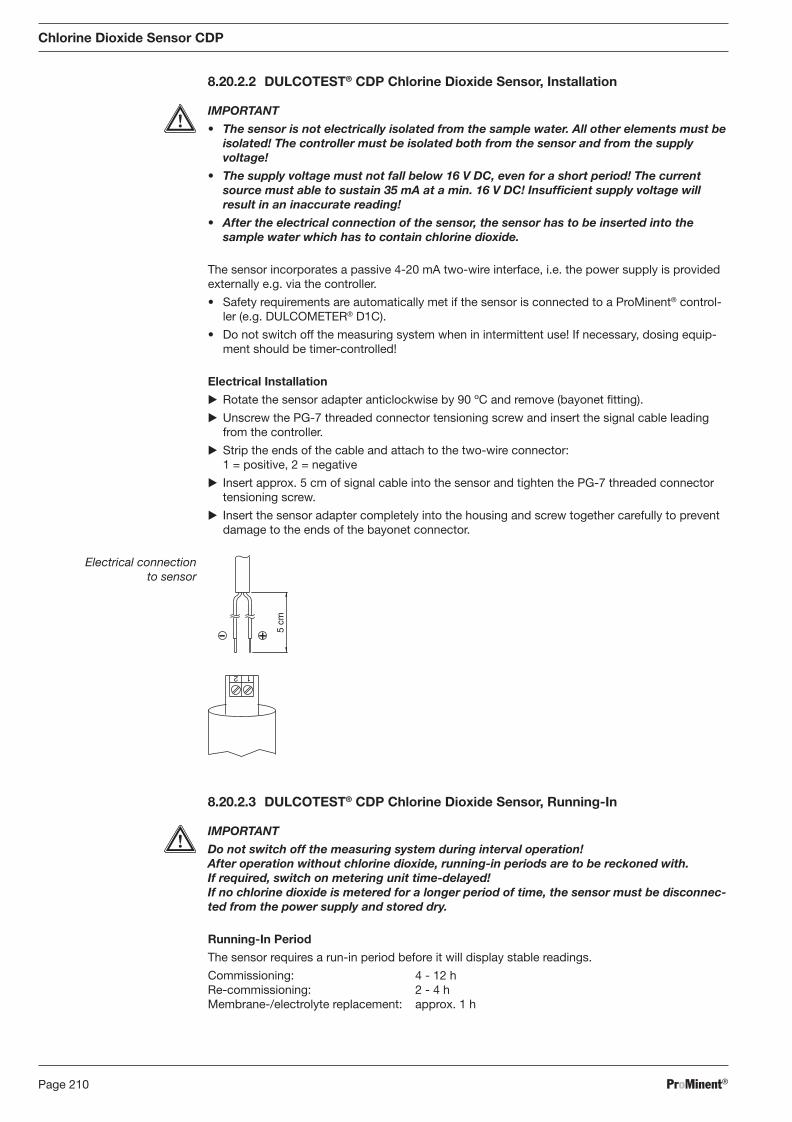
ProMinent®Page 210
8.20.2.2 DULCOTEST® CDP Chlorine Dioxide Sensor, Installation
IMPORTANT
• The sensor is not electrically isolated from the sample water. All other elements must be isolated! The controller must be isolated both from the sensor and from the supply voltage!
• The supply voltage must not fall below 16 V DC, even for a short period! The current source must able to sustain 35 mA at a min. 16 V DC! Insuffi cient supply voltage will result in an inaccurate reading!
• After the electrical connection of the sensor, the sensor has to be inserted into the sample water which has to contain chlorine dioxide.
The sensor incorporates a passive 4-20 mA two-wire interface, i.e. the power supply is provided externally e.g. via the controller.
• Safety requirements are automatically met if the sensor is connected to a ProMinent® con trol-ler (e.g. DULCOMETER® D1C).
• Do not switch off the measuring system when in intermittent use! If necessary, dosing equip-ment should be timer-controlled!
Electrical Installation
� Rotate the sensor adapter anticlockwise by 90 ºC and remove (bayonet fi tting).
� Unscrew the PG-7 threaded connector tensioning screw and insert the signal cable leading from the controller.
� Strip the ends of the cable and attach to the two-wire connector: 1 = positive, 2 = negative
� Insert approx. 5 cm of signal cable into the sensor and tighten the PG-7 threaded connector tensioning screw.
� Insert the sensor adapter completely into the housing and screw together carefully to prevent damage to the ends of the bayonet connector.
Electrical connection to sensor
1 2
5 cm
8.20.2.3 DULCOTEST® CDP Chlorine Dioxide Sensor, Running-In
IMPORTANT
Do not switch off the measuring system during interval operation! After operation without chlorine dioxide, running-in periods are to be reckoned with. If required, switch on metering unit time-delayed! If no chlorine dioxide is metered for a longer period of time, the sensor must be disconnec-ted from the power supply and stored dry.
Running-In Period
The sensor requires a run-in period before it will display stable readings.
Commissioning: 4 - 12 h Re-commissioning: 2 - 4 h Membrane-/electrolyte replacement: approx. 1 h
Chlorine Dioxide Sensor CDP
BA_DR_001_02_09_GB.indd 210BA_DR_001_02_09_GB.indd 210 24.02.2009 12:24:14 Uhr24.02.2009 12:24:14 Uhr
ProMinent® Page 211
Chlorine Dioxide Sensor CDP
8.20.2.4 DULCOTEST® CDP Chlorine Dioxide Sensor, Calibration
Calibration
The sensor can be calibrated after the run-in period.
IMPORTANT
• A slope test must be carried out after replacing the diaphragm cap or electrolyte!
• Slope tests must be carried out at regular intervals to ensure correct functioning of the sensor! For testing drinking water, calibration of the sensor every 3 - 4 weeks is suf fi -cient.
• Avoid incorrect dosing due to air bubbles in the water. Air bubbles clinging to the sensor diaphragm can reduce the measured variable and thereby lead to overdosing.
• Observe applicable national directives for calibration intervals!
Preconditions • The sensor is run-in
• Constant fl ow to the in-line probe housing
• Constant sample water temperature
• Same sample water and sensor temperatures (wait approx. 15 min.)
Zero Point Calibration
If a ProMinent controller is being used to operate the sensor there is no need for zero point calibration. Zero point calibration should be carried out, however, if operating the sensor in the lower measurement range.
Preconditions � Insert the sensor into a container of clean, ozone-, chlorine and ClO2-free water.
� Stir with the sensor until the measured variable displayed at the controller has remained stable for 5 min.
� Calibrate the controller to zero in accordance with the operating instructions.
� Replace sensor into the in-line probe housing (DGM; DLG).
Slope Test
� Determine the chlorine dioxide content in the sample water using an appropriate measurement device (e.g. DPD-1).
� Set the resulting value at the controller in accordance with the operating instructions.
Repeat calibration after 1 day!
NOTE
Calibration at high temperatures
As chlorine dioxide, in contrast to chlorine, is only physically dissolved in water, it evap o-rates out of the liquid very quickly at high temperatures (> 30 °C). We therefore rec om-mend that you act quickly when carrying out the DPD measurement. There should be no more than 1 min. between the sample extraction and the addition of reagents. Therefore the reagent should be added directly at the sample extraction point and measurement should follow as soon as possible afterwards in the laboratory.
BA_DR_001_02_09_GB.indd 211BA_DR_001_02_09_GB.indd 211 24.02.2009 12:24:15 Uhr24.02.2009 12:24:15 Uhr
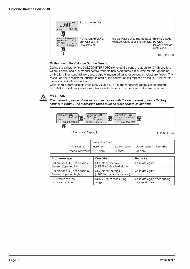
ProMinent®Page 212
Possible values
Initial value Increment Lower value Upper value Remarks
Measured value 0.01 ppm 0 ppm 20 ppm
Error message Condition Remarks
Calibration ClO2 not possible! ClO2 slope too low Calibrate again Sensor slope too low (<25 % of standard slope)
Calibration ClO2 not possible! ClO2 slope too high Calibrate again Sensor slope too high (>300 % of standard slope)
DPD value too low DPD <2 % of measuring Calibrate again after adding DPD > x.xx ppm range chorine dioxide
calibration ClO2zero p.: 4.00 mAslope:
6.50 mA/ppm
calibration ClO2DPD-value:
0.60 ppmtemp.: 30.0 °C
calibration ClO2zero p.: 4.00 mAslope:
6.75 mA/ppm
Permanent Display 1 D1C2-CIO2-012-GB
Chlorine Dioxide Sensor CDP
Calibration of the Chlorine Dioxide Sensor
During the calibration the DULCOMETER® D1C switches the control outputs to “0”. Exception: where a basic load or a manual control variable has been entered it is retained throughout the calibration. The standard mA signal outputs (measured value or correction value) are frozen. The measured value registered during the start of the calibration is proposed as the DPD value; this value is adjustable (arrow keys!). Calibration is only possible if the DPD value is ≥2 % of the measuring range. On successful completion of calibration, all error checks which refer to the measured value are restarted.
IMPORTANT
The measuring range of the sensor must agree with the set measuring range (factory setting: 0–2 ppm). The measuring range must be reset prior to calibration!
Positive values of setting variable: chlorine dioxideNegative values of setting variable: De-ClO2
(chlorine dioxidedestruction)
auto.: 30.0 °C
Permanent display 1
Permanent display 2only with control(w = setpoint)
ppm0.60
mea. val. 0.60 ppmfeed fwd: 70 %ctrl out: 59 %w: 0.60 ppm
D1C2-CIO2-011-GB
BA_DR_001_02_09_GB.indd 212BA_DR_001_02_09_GB.indd 212 24.02.2009 12:24:15 Uhr24.02.2009 12:24:15 Uhr
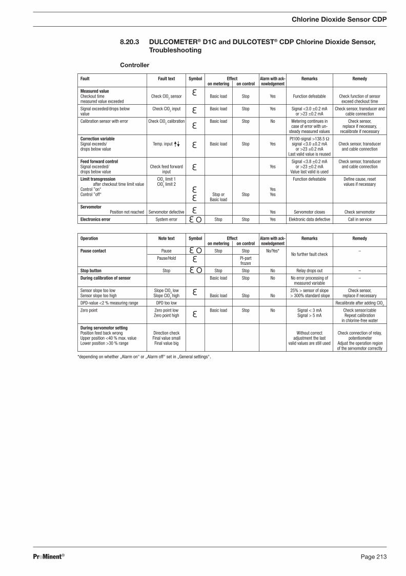
ProMinent® Page 213
*depending on whether „Alarm on“ or „Alarm off“ set in „General settings“.
Operation Note text Symbol Effect Alarm with ack- Remarks Remedy on metering on control nowledgement
Pause contact Pause Stop Stop No/Yes* No further fault check
–
Pause/Hold PI-part frozen
Stop button Stop Stop Stop No Relay drops out –
During calibration of sensor Basic load Stop No No error processing of – measured variable
Sensor slope too low Slope ClO2 low 25% > sensor of slope Check sensor, Sensor slope too high Slope ClO2 high Basic load Stop No > 300% standard slope replace if necessary
DPD-value <2 % measuring range DPD too low Recalibrate after adding ClO2
Zero point Zero point low Basic load Stop No Signal < 3 mA Check sensor/cable Zero point high Signal > 5 mA Repeat calibration in chlorine-free water
During servomotor setting Position feed back wrong Direction check Without correct Check connection of relay, Upper position <40 % max. value Final value small adjustment the last potentiometer Lower position >30 % range Final value big valid values are still used Adjust the operation region of the servomotor correctly
Fault Fault text Symbol Effect Alarm with ack- Remarks Remedy on metering on control nowledgement
Measured value Checkout time Check ClO2 sensor Basic load Stop Yes Function defeatable Check function of sensor measured value exceeded exceed checkout time
Signal exceeded/drops below Check ClO2 input Basic load Stop Yes Signal <3.0 ±0.2 mA Check sensor, transducer and value or >23 ±0.2 mA cable connection
Calibration sensor with error Check ClO2 calibration Basic load Stop No Metering continues in Check sensor, case of error with un- replace if necessary, steady measured values recalibrate if necessary
Correction variable Pt100-signal >138.5 Ω Signal exceeds/ Temp. input Basic load Stop Yes signal <3.0 ±0.2 mA Check sensor, transducer drops below value or >23 ±0.2 mA and cable connection Last valid value is reused
Feed forward control Signal <3.8 ±0.2 mA Check sensor, transducer Signal exceeded/ Check feed forward Yes or >23 ±0.2 mA and cable connection drops below value input Value last valid is used
Limit transgression ClO2 limit 1 Function defeatable Defi ne cause, reset
after checkout time limit value ClO2 limit 2 values if necessary Control ”on“ Yes Control ”off“ Stop or Stop Yes Basic load
Servomotor Position not reached Servomotor defective Yes Servomotor closes Check servomotor
Electronics error System error Stop Stop Yes Elektronic data defective Call in service
Chlorine Dioxide Sensor CDP
8.20.3 DULCOMETER® D1C and DULCOTEST® CDP Chlorine Dioxide Sensor, Troubleshooting
Controller
BA_DR_001_02_09_GB.indd 213BA_DR_001_02_09_GB.indd 213 24.02.2009 12:24:15 Uhr24.02.2009 12:24:15 Uhr
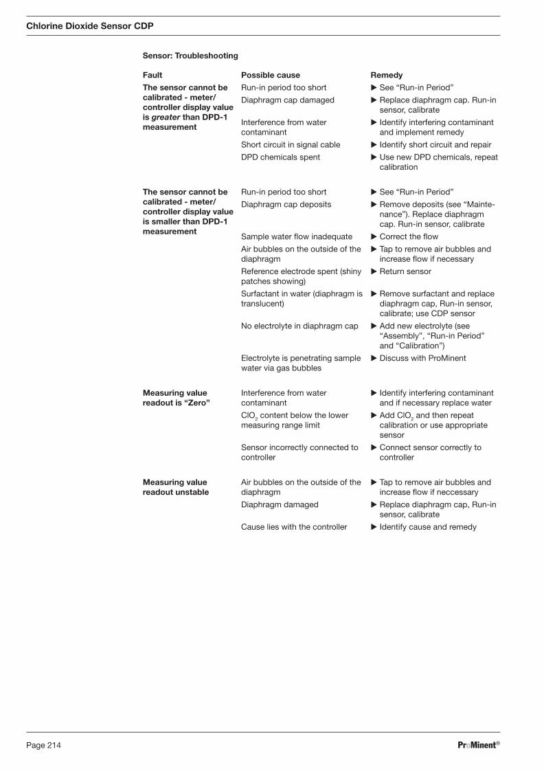
ProMinent®Page 214
Chlorine Dioxide Sensor CDP
Sensor: Troubleshooting
Fault
The sensor cannot be calibrated - meter/controller display value is greater than DPD-1 measurement
The sensor cannot be calibrated - meter/controller display value is smaller than DPD-1 measurement
Measuring value readout is “Zero”
Measuring value readout unstable
Possible cause
Run-in period too short
Diaphragm cap damaged
Interference from water con tam inant
Short circuit in signal cable
DPD chemicals spent
Run-in period too short
Diaphragm cap deposits
Sample water fl ow inadequate
Air bubbles on the outside of the diaphragm
Reference electrode spent (shiny patches showing)
Surfactant in water (diaphragm is translucent)
No electrolyte in diaphragm cap
Electrolyte is penetrating sample water via gas bubbles
Interference from water con tam inant
ClO2 content below the lower measuring range limit
Sensor incorrectly connected to controller
Air bubbles on the outside of the diaphragm
Diaphragm damaged
Cause lies with the controller
Remedy
� See “Run-in Period”
� Replace diaphragm cap. Run-in sensor, calibrate
� Identify interfering contaminant and implement remedy
� Identify short circuit and repair
� Use new DPD chemicals, repeat calibration
� See “Run-in Period”
� Remove deposits (see “Main te-nance”). Replace diaphragm cap. Run-in sensor, calibrate
� Correct the fl ow
� Tap to remove air bubbles and increase fl ow if necessary
� Return sensor
� Remove surfactant and replace diaphragm cap, Run-in sensor, calibrate; use CDP sensor
� Add new electrolyte (see “Assembly”, “Run-in Period” and “Calibration”)
� Discuss with ProMinent
� Identify interfering contaminant and if necessary replace water
� Add ClO2 and then repeat calibration or use appropriate sensor
� Connect sensor correctly to controller
� Tap to remove air bubbles and increase fl ow if neccessary
� Replace diaphragm cap, Run-in sensor, calibrate
� Identify cause and remedy
BA_DR_001_02_09_GB.indd 214BA_DR_001_02_09_GB.indd 214 24.02.2009 12:24:15 Uhr24.02.2009 12:24:15 Uhr
ProMinent® Page 215
Chlorine Dioxide Sensor CDP
8.20.4 DULCOMETER® D1C Measured Variable Chlordioxid and DULCOTEST® CDP Chlorine Dioxide Sensor, Maintenance
The DULCOMETER® controller type D1C for the measured variable chlorine dioxide is maintenance-free.
Sensor
IMPORTANT
� The sensor must be regularly serviced in order to avoid overdosing due to sensor failure!
� Observe applicable national directives for servicing intervals!
� Do not touch the electrodes or bring them into contact with greasy substances!
Maintenance interval Daily/weekly servicing intervals depending upon application.
Maintenance Work
� Check the sensor display value at the controller using an appropriate chlorine dioxide measuring system (e.g. DPD-1).
� Recalibrate the sensor if necessary.
Cleaning the Membrane
If the membrane is dirty and is preventing calibration of the sensor you can try to clean the membrane gently.
First dismantle the sensor as described in the sensor dismantling section. Observe safety guidelines! Removal of surface contamination.
� Rinse the membrane under a gentle stream of cold water.
IMPORTANT
• Never try to clean the membrane with acids/alkalis or mechanical means (brush or similar).
• If the sensor cannot be calibrated after membrane cleaning, the membrane cap has to be replaced by a new one.
Replacing the Membrane
If calibration is no longer possible after cleaning the membrane, or if the membrane is damaged it must be replaced.
At fi rst, the old membrane cap is removed and the gel adhering to the electrodes is rinsed off ander running water as best as possible. Remainders of the gel can be removed using a soft paper tissue. Wipe carefully across the sensor, in particular the reference system (brown ring). Then, fi ll a new membrane cap with gel electrolyte and screw it on (see “Mounting”).
BA_DR_001_02_09_GB.indd 215BA_DR_001_02_09_GB.indd 215 24.02.2009 12:24:15 Uhr24.02.2009 12:24:15 Uhr
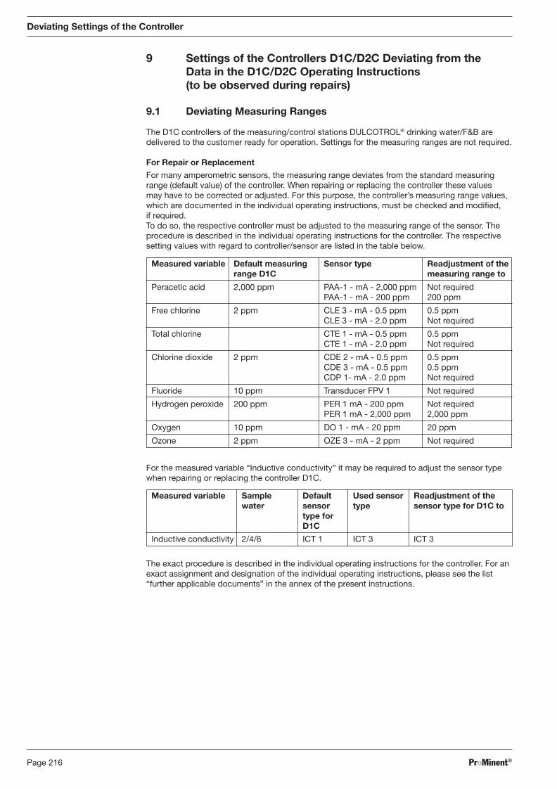
ProMinent®Page 216
Measured variable Sample Default Used sensor Readjustment of the water sensor type sensor type for D1C to type for D1C
Inductive conductivity 2/4/6 ICT 1 ICT 3 ICT 3
Deviating Settings of the Controller
9 Settings of the Controllers D1C/D2C Deviating from the Data in the D1C/D2C Operating Instructions (to be observed during repairs)
9.1 Deviating Measuring Ranges
The D1C controllers of the measuring/control stations DULCOTROL® drinking water/F&B are delivered to the customer ready for operation. Settings for the measuring ranges are not required.
For Repair or Replacement
For many amperometric sensors, the measuring range deviates from the standard measuring range (default value) of the controller. When repairing or replacing the controller these values may have to be corrected or adjusted. For this purpose, the controller’s measuring range values, which are documented in the individual operating instructions, must be checked and modifi ed, if required.
To do so, the respective controller must be adjusted to the measuring range of the sensor. The procedure is described in the individual operating instructions for the controller. The respective setting values with regard to controller/sensor are listed in the table below.
Measured variable Default measuring Sensor type Readjustment of the range D1C measuring range to
Peracetic acid 2,000 ppm PAA-1 - mA - 2,000 ppm Not required PAA-1 - mA - 200 ppm 200 ppm
Free chlorine 2 ppm CLE 3 - mA - 0.5 ppm 0.5 ppm CLE 3 - mA - 2.0 ppm Not required
Total chlorine CTE 1 - mA - 0.5 ppm 0.5 ppm CTE 1 - mA - 2.0 ppm Not required
Chlorine dioxide 2 ppm CDE 2 - mA - 0.5 ppm 0.5 ppm CDE 3 - mA - 0.5 ppm 0.5 ppm CDP 1- mA - 2.0 ppm Not required
Fluoride 10 ppm Transducer FPV 1 Not required
Hydrogen peroxide 200 ppm PER 1 mA - 200 ppm Not required PER 1 mA - 2,000 ppm 2,000 ppm
Oxygen 10 ppm DO 1 - mA - 20 ppm 20 ppm
Ozone 2 ppm OZE 3 - mA - 2 ppm Not required
For the measured variable “Inductive conductivity” it may be required to adjust the sensor type when repairing or replacing the controller D1C.
The exact procedure is described in the individual operating instructions for the controller. For an exact assignment and designation of the individual operating instructions, please see the list “further applicable documents” in the annex of the present instructions.
BA_DR_001_02_09_GB.indd 216BA_DR_001_02_09_GB.indd 216 24.02.2009 12:24:15 Uhr24.02.2009 12:24:15 Uhr
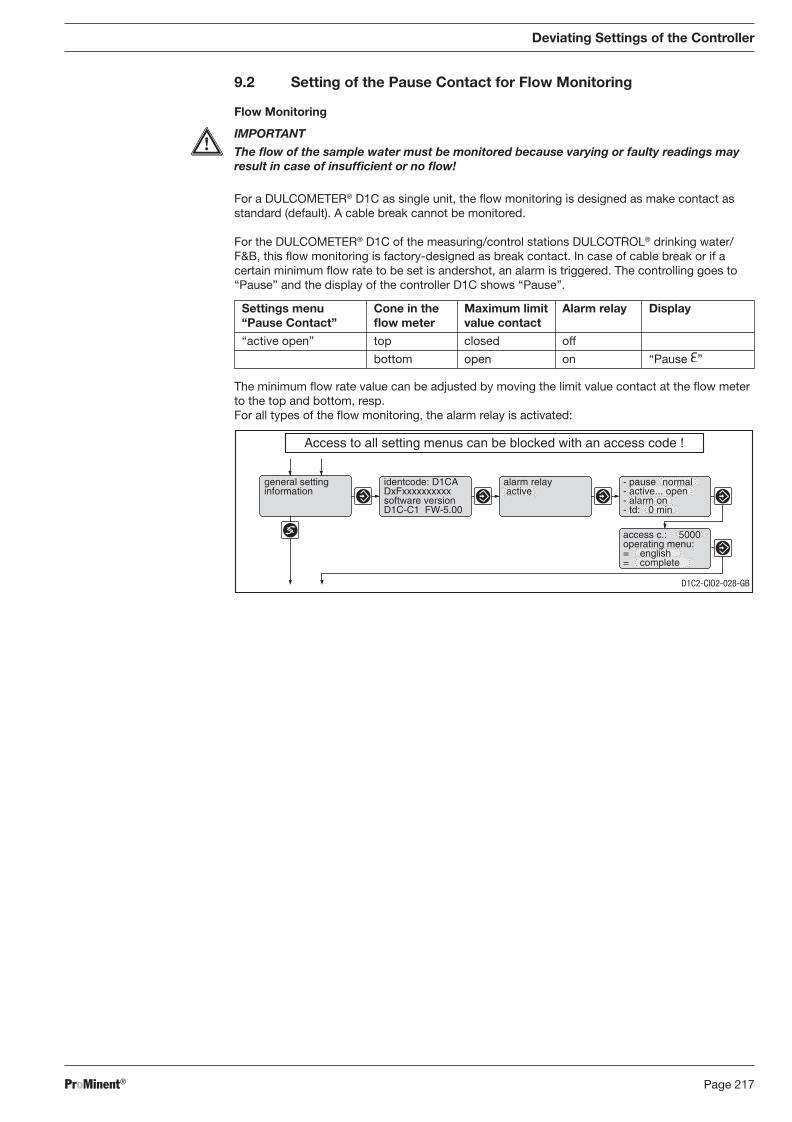
ProMinent® Page 217
Deviating Settings of the Controller
9.2 Setting of the Pause Contact for Flow Monitoring
Flow Monitoring
IMPORTANT
The fl ow of the sample water must be monitored because varying or faulty readings may result in case of insuffi cient or no fl ow!
For a DULCOMETER® D1C as single unit, the fl ow monitoring is designed as make contact as standard (default). A cable break cannot be monitored.
For the DULCOMETER® D1C of the measuring/control stations DULCOTROL® drinking water/F&B, this fl ow monitoring is factory-designed as break contact. In case of cable break or if a certain minimum fl ow rate to be set is andershot, an alarm is triggered. The controlling goes to “Pause” and the display of the controller D1C shows “Pause”.
The minimum fl ow rate value can be adjusted by moving the limit value contact at the fl ow meter to the top and bottom, resp. For all types of the fl ow monitoring, the alarm relay is activated:
alarm relay active
Access to all setting menus can be blocked with an access code !
general settinginformation
identcode: D1CADxFxxxxxxxxxxsoftware versionD1C-C1 FW-5.00
access c.: 5000operating menu:= english= complete
- pause normal- active... open- alarm on- td: 0 min
D1C2-CIO2-028-GB
Settings menu Cone in the Maximum limit Alarm relay Display “Pause Contact” fl ow meter value contact
“active open” top closed off
bottom open on “Pause ”
BA_DR_001_02_09_GB.indd 217BA_DR_001_02_09_GB.indd 217 24.02.2009 12:24:15 Uhr24.02.2009 12:24:15 Uhr
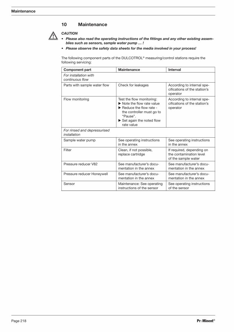
ProMinent®Page 218
10 Maintenance
CAUTION
• Please also read the operating instructions of the fi ttings and any other existing as sem-blies such as sensors, sample water pump … !
• Please observe the safety data sheets for the media involved in your process!
The following component parts of the DULCOTROL® measuring/control stations require the following servicing:
Maintenance
Component part Maintenance Interval
For installation with continuous fl ow
Parts with sample water fl ow Check for leakages According to internal spe-cifi cations of the station’s operator
Flow monitoring Test the fl ow monitoring: According to internal spe- � Note the fl ow rate value cifi cations of the station’s � Reduce the fl ow rate - operator the controller must go to “Pause”. � Set again the noted fl ow rate value
For rinsed and depressurised installation
Sample water pump See operating instructions See operating instructions in the annex in the annex
Filter Clean, if not possible, If required, depending on replace cartridge the contamination level
of the sample water
Pressure reducer V82 See manufacturer’s docu- See manufacturer’s docu- mentation in the annex mentation in the annex
Pressure reducer Honeywell See manufacturer’s docu- See manufacturer’s docu- mentation in the annex mentation in the annex
Sensor Maintenance: See operating See operating instructions instructions of the sensor of the sensor
BA_DR_001_02_09_GB.indd 218BA_DR_001_02_09_GB.indd 218 24.02.2009 12:24:15 Uhr24.02.2009 12:24:15 Uhr
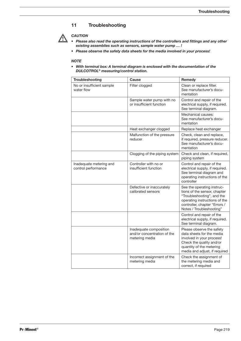
ProMinent® Page 219
Troubleshooting
11 Troubleshooting
CAUTION
• Please also read the operating instructions of the controllers and fi ttings and any other existing assemblies such as sensors, sample water pump … !
• Please observe the safety data sheets for the media involved in your process!
NOTE
• With terminal box: A terminal diagram is enclosed with the documentation of the DULCOTROL® measuring/control station.
Troubleshooting Cause Remedy
No or insuffi cient sample Filter clogged Clean or replace fi lter. water fl ow See manufacturer’s docu-
mentation
Sample water pump with no Control and repair of the or insuffi cient function electrical supply, if required.
See terminal diagram.
Mechanical causes: See manufacturer’s docu-mentation
Heat exchanger clogged Replace heat exchanger
Malfunction of the pressure Check, clean and replace, reducer if required, pressure reducer.
See manufacturer’s docu-mentation
Clogging of the piping system Check and clean, if required, piping system
Inadequate metering and Controller with no or Control and repair of the control performance insuffi cient function electrical supply, if required.
See terminal diagram and operating instructions of the controller
Defective or inaccurately See the operating instruc- calibrated sensors tions of the sensor, chapter
“Troubleshooting”, and the operating instructions of the controller, chapter “Errors / Notes / Troubleshooting”
Control and repair of the electrical supply, if required. See terminal diagram.
Inadequate composition Please observe the safety and/or concentration of the data sheets for the media metering media involved in your process!
Check the quality and/or quantity of the metering media and adjust, if required
Incorrect assignment of the Check the assignment of metering media the metering media and
correct, if required
BA_DR_001_02_09_GB.indd 219BA_DR_001_02_09_GB.indd 219 24.02.2009 12:24:15 Uhr24.02.2009 12:24:15 Uhr
ProMinent®Page 220
12 Decommissioning and Disposal
CAUTION
• The controller may only be disconnected from the mains supply by a qualifi ed elec tri-cian!
• Thoroughly fl ush the sample water line with a suitable medium (see data safety sheet)!
• Please also read the operating instructions of the controllers and fi ttings and any other existing assemblies such as sensors, sample water pump … !
• Also in case of a short time of decommissioning (up to 12 h): Observe the operating instructions of the sensor!
• Please observe the safety data sheets for the media involved in your process!
� In case of temporary or long-term decommissioning. Close the ball valves such that the sensors remain surroanded by sample water.
12.1 Temporary or Long-Term Decommissioning
CAUTION
• Please observe the safety data sheets for the media involved in your process!
• Please also read the operating instructions of the controllers and fi ttings and any other existing assemblies such as sensors, sample water pump … !
12.2 Final Decommissioning
CAUTION
• Please observe the safety data sheets for the media involved in your process!
• Please observe the respective applicable local regulations!
• In Germany, used parts can be disposed of at the municipal collection points of the cities and municipalities. You may return the used parts to the ProMinent Dosiertechnik GmbH, Heidelberg, against a low fee and prepaid postage.
• Please also read the operating instructions of the controllers and fi ttings and any other existing assemblies such as sensors, sample water pump … !
• The electrolyte of the sensors can be caustic!
• Collect leaking electrolyte. Wear suitable gloves and safety goggles.
• Remove contaminations with a lot of water. Dispose of waste water in a way harmless to the environment.
13 Replacement Parts
Please also note the listings in the operating instructions of the controllers and fi ttings and any other existing assemblies such as sensors, sample water pump … ! Any other replacement parts can be ordered from our customer service.
Decommissioning and Disposal / Replacement Parts
BA_DR_001_02_09_GB.indd 220BA_DR_001_02_09_GB.indd 220 24.02.2009 12:24:15 Uhr24.02.2009 12:24:15 Uhr
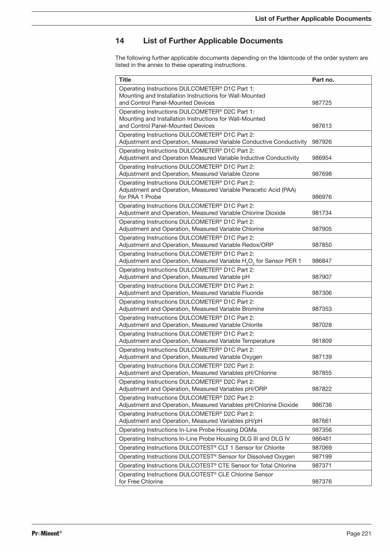
ProMinent® Page 221
Title Part no.
Operating Instructions DULCOMETER® D1C Part 1: Mounting and Installation Instructions for Wall-Mounted and Control Panel-Mounted Devices 987725
Operating Instructions DULCOMETER® D2C Part 1: Mounting and Installation Instructions for Wall-Mounted and Control Panel-Mounted Devices 987613
Operating Instructions DULCOMETER® D1C Part 2: Adjustment and Operation, Measured Variable Conductive Conductivity 987926
Operating Instructions DULCOMETER® D1C Part 2: Adjustment and Operation Measured Variable Inductive Conductivity 986954
Operating Instructions DULCOMETER® D1C Part 2: Adjustment and Operation, Measured Variable Ozone 987698
Operating Instructions DULCOMETER® D1C Part 2: Adjustment and Operation, Measured Variable Peracetic Acid (PAA) for PAA 1 Probe 986976
Operating Instructions DULCOMETER® D1C Part 2: Adjustment and Operation, Measured Variable Chlorine Dioxide 981734
Operating Instructions DULCOMETER® D1C Part 2: Adjustment and Operation, Measured Variable Chlorine 987905
Operating Instructions DULCOMETER® D1C Part 2: Adjustment and Operation, Measured Variable Redox/ORP 987850
Operating Instructions DULCOMETER® D1C Part 2: Adjustment and Operation, Measured Variable H2O2 for Sensor PER 1 986847
Operating Instructions DULCOMETER® D1C Part 2: Adjustment and Operation, Measured Variable pH 987907
Operating Instructions DULCOMETER® D1C Part 2: Adjustment and Operation, Measured Variable Fluoride 987306
Operating Instructions DULCOMETER® D1C Part 2: Adjustment and Operation, Measured Variable Bromine 987353
Operating Instructions DULCOMETER® D1C Part 2: Adjustment and Operation, Measured Variable Chlorite 987028
Operating Instructions DULCOMETER® D1C Part 2: Adjustment and Operation, Measured Variable Temperature 981809
Operating Instructions DULCOMETER® D1C Part 2: Adjustment and Operation, Measured Variable Oxygen 987139
Operating Instructions DULCOMETER® D2C Part 2: Adjustment and Operation, Measured Variables pH/Chlorine 987855
Operating Instructions DULCOMETER® D2C Part 2: Adjustment and Operation, Measured Variables pH/ORP 987822
Operating Instructions DULCOMETER® D2C Part 2: Adjustment and Operation, Measured Variables pH/Chlorine Dioxide 986736
Operating Instructions DULCOMETER® D2C Part 2: Adjustment and Operation, Measured Variables pH/pH 987661
Operating Instructions In-Line Probe Housing DGMa 987356
Operating Instructions In-Line Probe Housing DLG III and DLG IV 986461
Operating Instructions DULCOTEST® CLT 1 Sensor for Chlorite 987069
Operating Instructions DULCOTEST® Sensor for Dissolved Oxygen 987199
Operating Instructions DULCOTEST® CTE Sensor for Total Chlorine 987371
Operating Instructions DULCOTEST® CLE Chlorine Sensor for Free Chlorine 987376
List of Further Applicable Documents
14 List of Further Applicable Documents
The following further applicable documents depending on the Identcode of the order system are listed in the annex to these operating instructions.
BA_DR_001_02_09_GB.indd 221BA_DR_001_02_09_GB.indd 221 24.02.2009 12:24:15 Uhr24.02.2009 12:24:15 Uhr
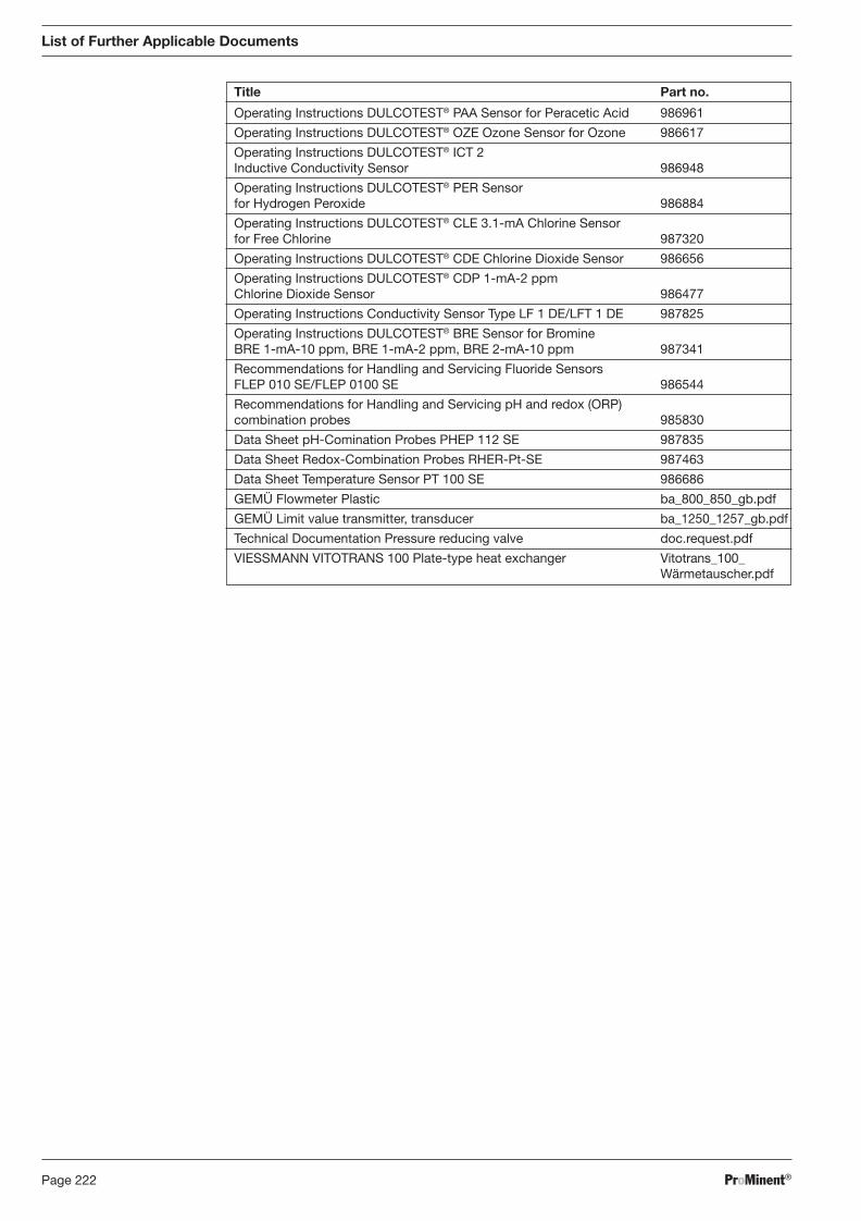
ProMinent®Page 222
Operating Instructions DULCOTEST® PAA Sensor for Peracetic Acid 986961
Operating Instructions DULCOTEST® OZE Ozone Sensor for Ozone 986617
Operating Instructions DULCOTEST® ICT 2 Inductive Conductivity Sensor 986948
Operating Instructions DULCOTEST® PER Sensor for Hydrogen Peroxide 986884
Operating Instructions DULCOTEST® CLE 3.1-mA Chlorine Sensor for Free Chlorine 987320
Operating Instructions DULCOTEST® CDE Chlorine Dioxide Sensor 986656
Operating Instructions DULCOTEST® CDP 1-mA-2 ppm Chlorine Dioxide Sensor 986477
Operating Instructions Conductivity Sensor Type LF 1 DE/LFT 1 DE 987825
Operating Instructions DULCOTEST® BRE Sensor for Bromine BRE 1-mA-10 ppm, BRE 1-mA-2 ppm, BRE 2-mA-10 ppm 987341
Recommendations for Handling and Servicing Fluoride Sensors FLEP 010 SE/FLEP 0100 SE 986544
Recommendations for Handling and Servicing pH and redox (ORP) combination probes 985830
Data Sheet pH-Comination Probes PHEP 112 SE 987835
Data Sheet Redox-Combination Probes RHER-Pt-SE 987463
Data Sheet Temperature Sensor PT 100 SE 986686
GEMÜ Flowmeter Plastic ba_800_850_gb.pdf
GEMÜ Limit value transmitter, transducer ba_1250_1257_gb.pdf
Technical Documentation Pressure reducing valve doc.request.pdf
VIESSMANN VITOTRANS 100 Plate-type heat exchanger Vitotrans_100_ Wärmetauscher.pdf
Title Part no.
List of Further Applicable Documents
BA_DR_001_02_09_GB.indd 222BA_DR_001_02_09_GB.indd 222 24.02.2009 12:24:15 Uhr24.02.2009 12:24:15 Uhr
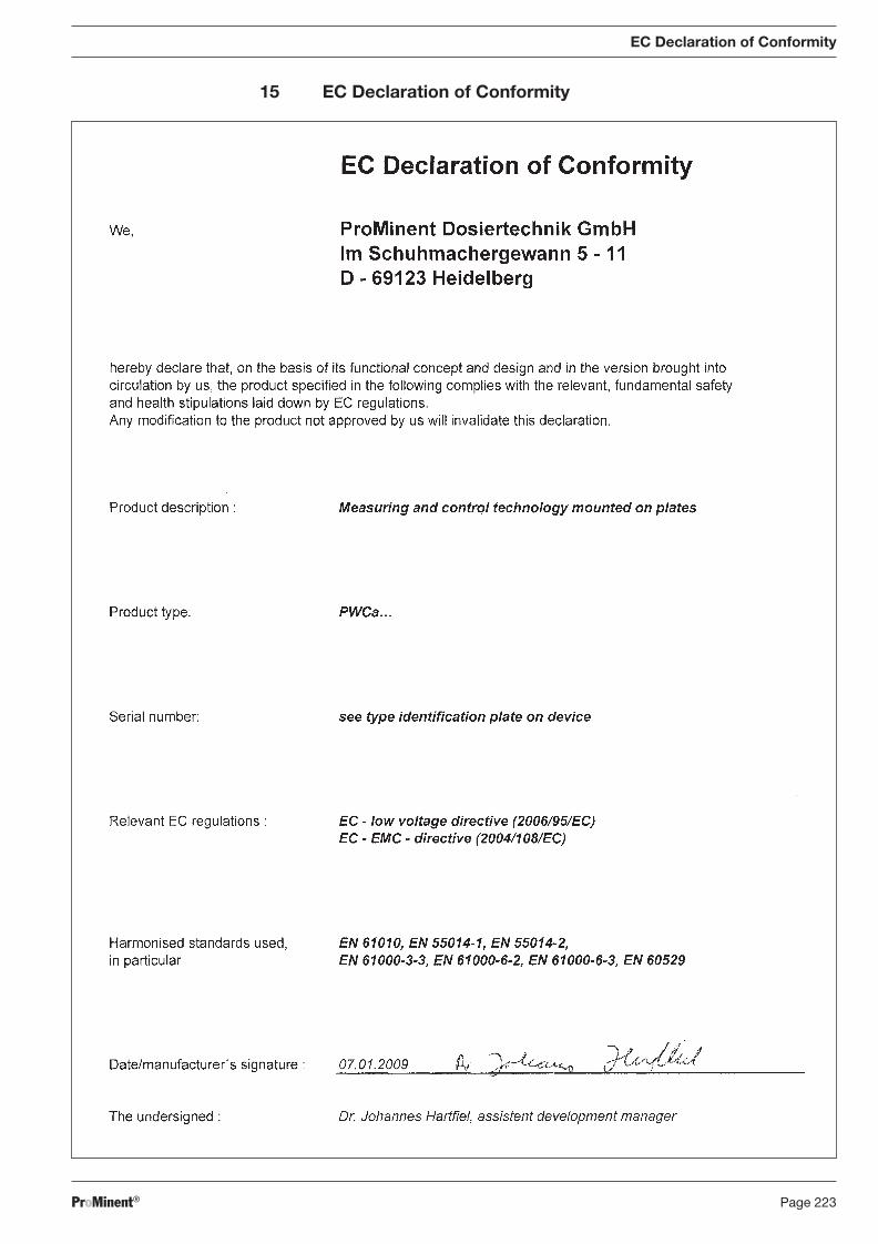
ProMinent® Page 223
EC Declaration of Conformity
15 EC Declaration of Conformity
BA_DR_001_02_09_GB.indd 223BA_DR_001_02_09_GB.indd 223 24.02.2009 12:24:15 Uhr24.02.2009 12:24:15 Uhr
ProMinent®Page 224
Addresses and delivery through manufacturer:
ProMinent Dosiertechnik GmbH Im Schuhmachergewann 5-11D-69123 HeidelbergGermany
Tel.: +49 6221 842-0Fax: +49 6221 842-419
BA_DR_001_02_09_GB.indd 224BA_DR_001_02_09_GB.indd 224 24.02.2009 12:24:15 Uhr24.02.2009 12:24:15 Uhr