Embed Size (px)
Citation preview
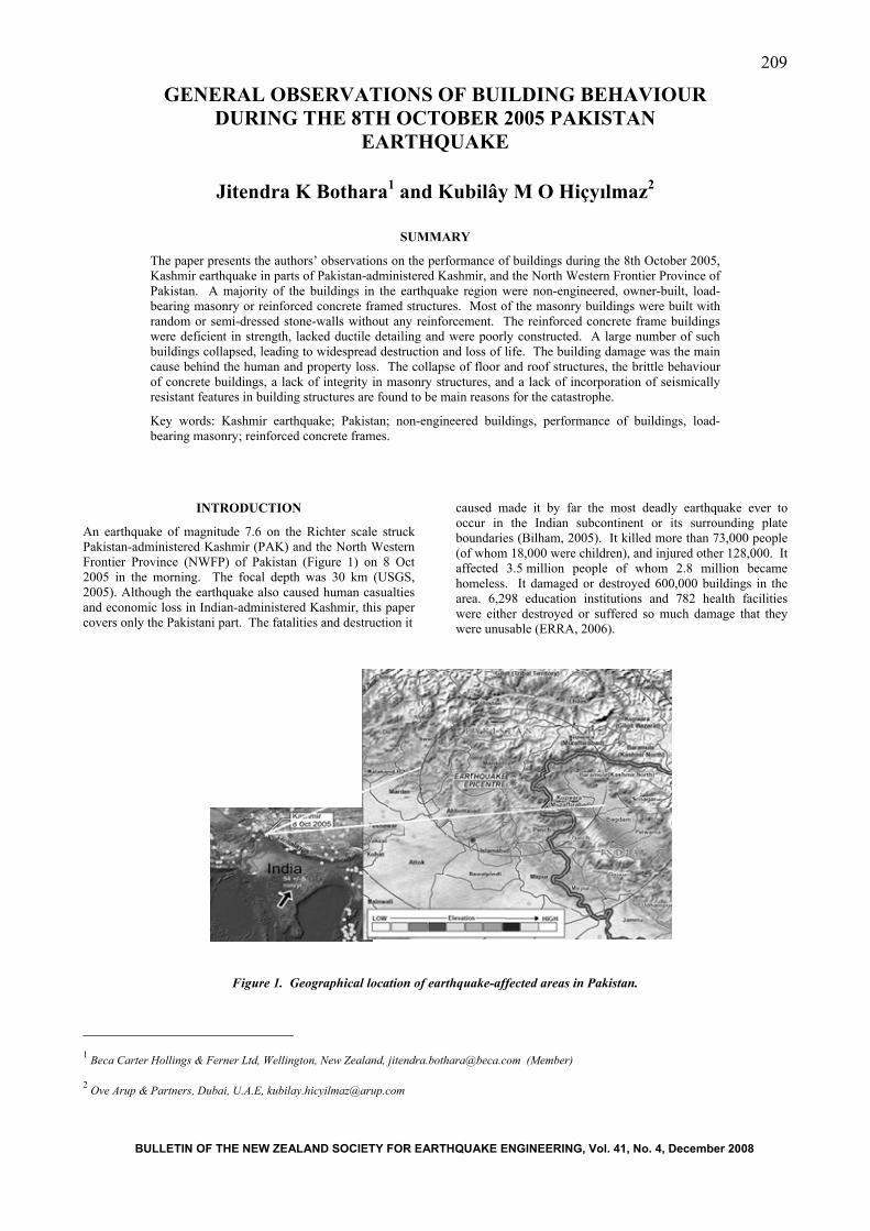
209
GENERAL OBSERVATIONS OF BUILDING BEHAVIOUR DURING THE 8TH OCTOBER 2005 PAKISTAN
EARTHQUAKE
Jitendra K Bothara1 and Kubilây M O Hiçyılmaz2
SUMMARY
1 Beca Carter Hollings & Ferner Ltd, Wellington, New Zealand, [email protected] (Member) 2 Ove Arup & Partners, Dubai, U.A.E, [email protected]
The paper presents the authors’ observations on the performance of buildings during the 8th October 2005, Kashmir earthquake in parts of Pakistan-administered Kashmir, and the North Western Frontier Province of Pakistan. A majority of the buildings in the earthquake region were non-engineered, owner-built, load-bearing masonry or reinforced concrete framed structures. Most of the masonry buildings were built with random or semi-dressed stone-walls without any reinforcement. The reinforced concrete frame buildings were deficient in strength, lacked ductile detailing and were poorly constructed. A large number of such buildings collapsed, leading to widespread destruction and loss of life. The building damage was the main cause behind the human and property loss. The collapse of floor and roof structures, the brittle behaviour of concrete buildings, a lack of integrity in masonry structures, and a lack of incorporation of seismically resistant features in building structures are found to be main reasons for the catastrophe.
Key words: Kashmir earthquake; Pakistan; non-engineered buildings, performance of buildings, load-bearing masonry; reinforced concrete frames.
INTRODUCTION
An earthquake of magnitude 7.6 on the Richter scale struck Pakistan-administered Kashmir (PAK) and the North Western Frontier Province (NWFP) of Pakistan (Figure 1) on 8 Oct 2005 in the morning. The focal depth was 30 km (USGS, 2005). Although the earthquake also caused human casualties and economic loss in Indian-administered Kashmir, this paper covers only the Pakistani part. The fatalities and destruction it
caused made it by far the most deadly earthquake ever to occur in the Indian subcontinent or its surrounding plate boundaries (Bilham, 2005). It killed more than 73,000 people (of whom 18,000 were children), and injured other 128,000. It affected 3.5 million people of whom 2.8 million became homeless. It damaged or destroyed 600,000 buildings in the area. 6,298 education institutions and 782 health facilities were either destroyed or suffered so much damage that they were unusable (ERRA, 2006).
Figure 1. Geographical location of earthquake-affected areas in Pakistan.
BULLETIN OF THE NEW ZEALAND SOCIETY FOR EARTHQUAKE ENGINEERING, Vol. 41, No. 4, December 2008
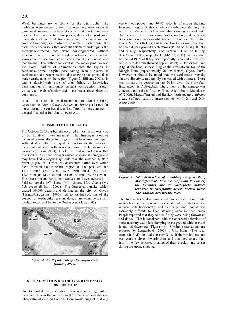
210 Weak buildings are to blame for the catastrophe. The buildings were generally weak because they were made of very weak materials such as stone in mud mortar, or were mostly likely constructed very poorly, despite being of good materials such as fired brick or stone in cement mortar, confined masonry, or reinforced concrete. Furthermore, the most likely scenario is that more than 95% of buildings in the earthquake-affected area were non-engineered without aseismic features. While building artisans clearly lacked knowledge of aseismic construction, so did engineers and technicians. The authors believe that the major problem was the overall failure of appreciation that the region is earthquake-prone, despite there having been a history of earthquakes and recent studies also showing the potential of major earthquakes in the region (Figure 2, Bilham, 2001). It was a classic/tragic case of total failure of knowledge dissemination on earthquake-resistant construction through virtually all levels of society and, in particular, the engineering community.
It has to be noted that well-maintained traditional building types such as Dhajji-dewari, Beetar and Batar performed far better during the earthquake, and suffered far less damage, in general, than other buildings, new or old.
SEISMICITY OF THE AREA
The October 2005 earthquake occurred almost at the west end of the Himalayan mountain range. The Himalayas is one of the most seismically active regions that have time and again suffered destructive earthquakes. Although the historical record of Pakistan earthquakes is thought to be incomplete (Ambraseys et al, 2004), it is known that an earthquake that occurred in 1555 near Srinagar caused substantial damage, and may have had a larger magnitude than the October 8, 2005 event (Figure 2). Other less destructive earthquakes which have affected the Kashmir region in the past are the 1842 Kunnar (Mw 7.5), 1878 Abbottabad (Mw 6.7), 1885 Srinagar (Mw 6.3), and the 1905 Kangra (Mw 7.8) events. The most recent large earthquakes to have occurred in Pakistan are the 1974 Pattan (Mw 6.2) and 1935 Quetta (Mw 7.5) events (Bilham, 2005). The Quetta earthquake, which caused 30,000 deaths and devastated the city of Quetta (Pararas-Carayannis, 2006), led to an introduction of the concept of earthquake-resistant design and construction in a modern sense, and led to the Quetta bond (Jain, 2005).
Figure 2. Earthquakes along Himalayan arch,
(Bilham, 2005).
STRONG MOTION RECORDS AND INTENSITY DISTRIBUTION
Due to limited instrumentation, there are no strong motion records of this earthquake within the zone of intense shaking. Observational data and reports from locals suggest a strong
vertical component and 30-45 seconds of strong shaking. However, Figure 3 shows intense earthquake shaking just north of Muzzaffarbad where the shaking caused total destruction of a military camp, soil spreading and landslide. Strong motion records in Abbottabad (35 km from the rupture zone), Murree (34 km), and Nilore (54 km) show maximum horizontal peak ground accelerations (PGA) of 0.231g, 0.078g and 0.026g, respectively; and vertical PGAs of 0.087g, 0.069 g and 0.03g, respectively (MAEC, 2005). A maximum horizontal PGA of 0.16g was reportedly recorded at the crest of the Tarbela Dam (located approximately 78 km distant) and 0.1g at the base, as was 0.1g at the downstream toe of the Mangla Dam (approximately 90 km distant) (Ilyas, 2005). However, it should be noted that the earthquake intensity showed directivity and rapidly attenuated with distance. There was virtually no destruction just 50 km away from the fault line, except in Abbottabad, where most of the damage was concentrated in the soft valley floor. According to Mahajan et al (2006), Muzzaffarabad and Balakot, both severely affected areas, suffered seismic intensities of MMI XI and XI+, respectively.
Figure 3. Total destruction of a military camp north of
Muzzaffarabad. Note the roof slabs thrown off the buildings and an earthquake induced landslide in background across Neelam River. The landslide dammed the river.
The first author’s discussions with many local people who were close to the epicentre revealed that the shaking was intense both horizontally and vertically; and that it was extremely difficult to keep standing even in open areas. People reported that they felt as if they were being thrown up and down. This is consistent with the observed behaviour of stone masonry walls just slumping to the ground without much lateral displacement (Figure 4). Similar observations are reported by Langenbach (2005) in Uri, India. The local people in PAK reported that they felt as if the whole mountain was coming closer towards them and that they would slam into it. A few reported blurring of their eyesight and senses during the strong shaking.
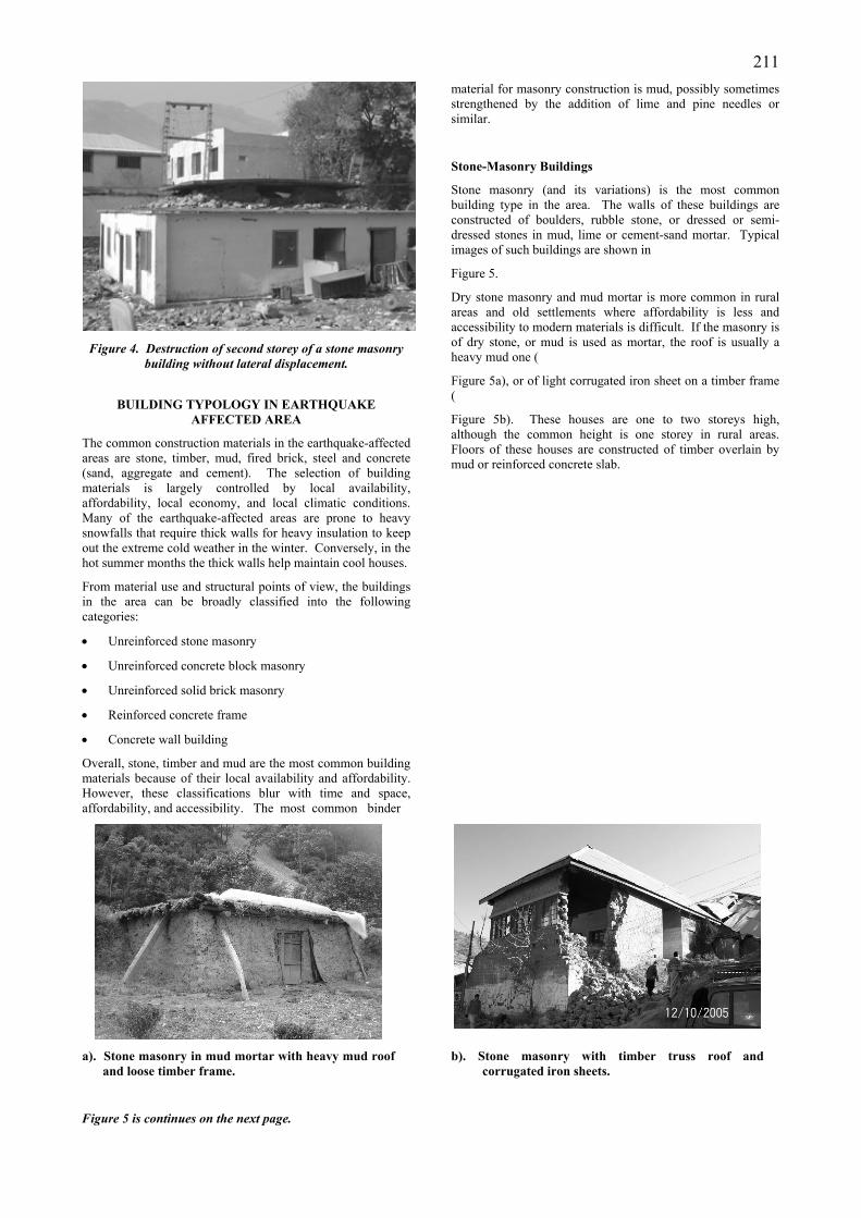
211
Figure 4. Destruction of second storey of a stone masonry
building without lateral displacement.
BUILDING TYPOLOGY IN EARTHQUAKE AFFECTED AREA
The common construction materials in the earthquake-affected areas are stone, timber, mud, fired brick, steel and concrete (sand, aggregate and cement). The selection of building materials is largely controlled by local availability, affordability, local economy, and local climatic conditions. Many of the earthquake-affected areas are prone to heavy snowfalls that require thick walls for heavy insulation to keep out the extreme cold weather in the winter. Conversely, in the hot summer months the thick walls help maintain cool houses.
From material use and structural points of view, the buildings in the area can be broadly classified into the following categories:
• Unreinforced stone masonry
• Unreinforced concrete block masonry
• Unreinforced solid brick masonry
• Reinforced concrete frame
• Concrete wall building
Overall, stone, timber and mud are the most common building materials because of their local availability and affordability. However, these classifications blur with time and space, affordability, and accessibility. The most common binder
material for masonry construction is mud, possibly sometimes strengthened by the addition of lime and pine needles or similar.
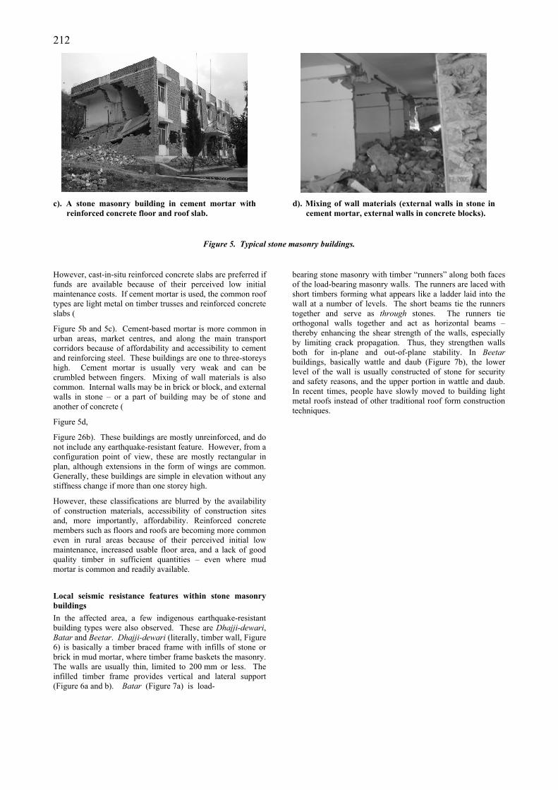
Stone-Masonry Buildings
Stone masonry (and its variations) is the most common building type in the area. The walls of these buildings are constructed of boulders, rubble stone, or dressed or semi-dressed stones in mud, lime or cement-sand mortar. Typical images of such buildings are shown in
Figure 5.
Dry stone masonry and mud mortar is more common in rural areas and old settlements where affordability is less and accessibility to modern materials is difficult. If the masonry is of dry stone, or mud is used as mortar, the roof is usually a heavy mud one (
Figure 5a), or of light corrugated iron sheet on a timber frame (
Figure 5b). These houses are one to two storeys high, although the common height is one storey in rural areas. Floors of these houses are constructed of timber overlain by mud or reinforced concrete slab.
a). Stone masonry in mud mortar with heavy mud roof and loose timber frame.
Figure 5 is continues on the next page.
b). Stone masonry with timber truss roof and corrugated iron sheets.
212
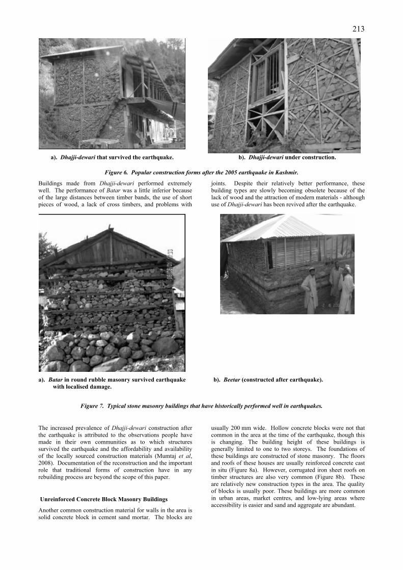
c). A stone masonry building in cement mortar with
reinforced concrete floor and roof slab. d). Mixing of wall materials (external walls in stone in
cement mortar, external walls in concrete blocks).
Figure 5. Typical stone masonry buildings.
However, cast-in-situ reinforced concrete slabs are preferred if funds are available because of their perceived low initial maintenance costs. If cement mortar is used, the common roof types are light metal on timber trusses and reinforced concrete slabs (
Figure 5b and 5c). Cement-based mortar is more common in urban areas, market centres, and along the main transport corridors because of affordability and accessibility to cement and reinforcing steel. These buildings are one to three-storeys high. Cement mortar is usually very weak and can be crumbled between fingers. Mixing of wall materials is also common. Internal walls may be in brick or block, and external walls in stone – or a part of building may be of stone and another of concrete (
Figure 5d,
Figure 26b). These buildings are mostly unreinforced, and do not include any earthquake-resistant feature. However, from a configuration point of view, these are mostly rectangular in plan, although extensions in the form of wings are common. Generally, these buildings are simple in elevation without any stiffness change if more than one storey high.
However, these classifications are blurred by the availability of construction materials, accessibility of construction sites and, more importantly, affordability. Reinforced concrete members such as floors and roofs are becoming more common even in rural areas because of their perceived initial low maintenance, increased usable floor area, and a lack of good quality timber in sufficient quantities – even where mud mortar is common and readily available.
Local seismic resistance features within stone masonry buildings In the affected area, a few indigenous earthquake-resistant building types were also observed. These are Dhajji-dewari, Batar and Beetar. Dhajji-dewari (literally, timber wall, Figure 6) is basically a timber braced frame with infills of stone or brick in mud mortar, where timber frame baskets the masonry. The walls are usually thin, limited to 200 mm or less. The infilled timber frame provides vertical and lateral support (Figure 6a and b). Batar (Figure 7a) is load-
bearing stone masonry with timber “runners” along both faces of the load-bearing masonry walls. The runners are laced with short timbers forming what appears like a ladder laid into the wall at a number of levels. The short beams tie the runners together and serve as through stones. The runners tie orthogonal walls together and act as horizontal beams – thereby enhancing the shear strength of the walls, especially by limiting crack propagation. Thus, they strengthen walls both for in-plane and out-of-plane stability. In Beetar buildings, basically wattle and daub (Figure 7b), the lower level of the wall is usually constructed of stone for security and safety reasons, and the upper portion in wattle and daub. In recent times, people have slowly moved to building light metal roofs instead of other traditional roof form construction techniques.
213
a). Dhajji-dewari that survived the earthquake. b). Dhajji-dewari under construction.
Figure 6. Popular construction forms after the 2005 earthquake in Kashmir.
Buildings made from Dhajji-dewari performed extremely well. The performance of Batar was a little inferior because of the large distances between timber bands, the use of short pieces of wood, a lack of cross timbers, and problems with
joints. Despite their relatively better performance, these building types are slowly becoming obsolete because of the lack of wood and the attraction of modern materials - although use of Dhajji-dewari has been revived after the earthquake.
a). Batar in round rubble masonry survived earthquake with localised damage.
b). Beetar (constructed after earthquake).
Figure 7. Typical stone masonry buildings that have historically performed well in earthquakes.
The increased prevalence of Dhajji-dewari construction after the earthquake is attributed to the observations people have made in their own communities as to which structures survived the earthquake and the affordability and availability of the locally sourced construction materials (Mumtaj et al, 2008). Documentation of the reconstruction and the important role that traditional forms of construction have in any rebuilding process are beyond the scope of this paper.
Unreinforced Concrete Block Masonry Buildings
Another common construction material for walls in the area is solid concrete block in cement sand mortar. The blocks are
usually 200 mm wide. Hollow concrete blocks were not that common in the area at the time of the earthquake, though this is changing. The building height of these buildings is generally limited to one to two storeys. The foundations of these buildings are constructed of stone masonry. The floors and roofs of these houses are usually reinforced concrete cast in situ (Figure 8a). However, corrugated iron sheet roofs on timber structures are also very common (Figure 8b). These are relatively new construction types in the area. The quality of blocks is usually poor. These buildings are more common in urban areas, market centres, and low-lying areas where accessibility is easier and sand and aggregate are abundant.
214
a). A block masonry building in Muzzaffarabad. b). A block masonry building with timber frame under
construction (after the earthquake).
Figure 8. A typical block masonry building.
Unreinforced Brick Masonry Buildings
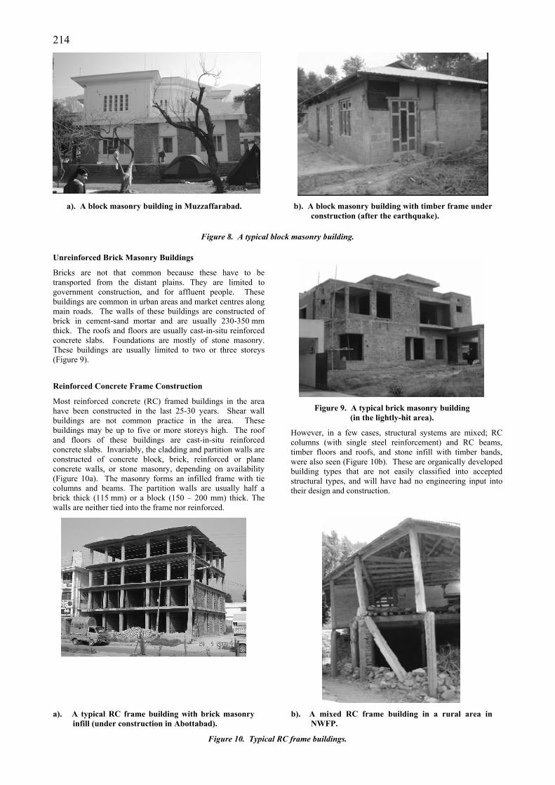
Bricks are not that common because these have to be transported from the distant plains. They are limited to government construction, and for affluent people. These buildings are common in urban areas and market centres along main roads. The walls of these buildings are constructed of brick in cement-sand mortar and are usually 230-350 mm thick. The roofs and floors are usually cast-in-situ reinforced concrete slabs. Foundations are mostly of stone masonry. These buildings are usually limited to two or three storeys (Figure 9).
Reinforced Concrete Frame Construction
Most reinforced concrete (RC) framed buildings in the area have been constructed in the last 25-30 years. Shear wall buildings are not common practice in the area. These buildings may be up to five or more storeys high. The roof and floors of these buildings are cast-in-situ reinforced concrete slabs. Invariably, the cladding and partition walls are constructed of concrete block, brick, reinforced or plane concrete walls, or stone masonry, depending on availability (Figure 10a). The masonry forms an infilled frame with tie columns and beams. The partition walls are usually half a brick thick (115 mm) or a block (150 – 200 mm) thick. The walls are neither tied into the frame nor reinforced.
Figure 9. A typical brick masonry building
(in the lightly-hit area).
However, in a few cases, structural systems are mixed; RC columns (with single steel reinforcement) and RC beams, timber floors and roofs, and stone infill with timber bands, were also seen (Figure 10b). These are organically developed building types that are not easily classified into accepted structural types, and will have had no engineering input into their design and construction.
a). A typical RC frame building with brick masonry
infill (under construction in Abottabad). b). A mixed RC frame building in a rural area in
NWFP.
Figure 10. Typical RC frame buildings.
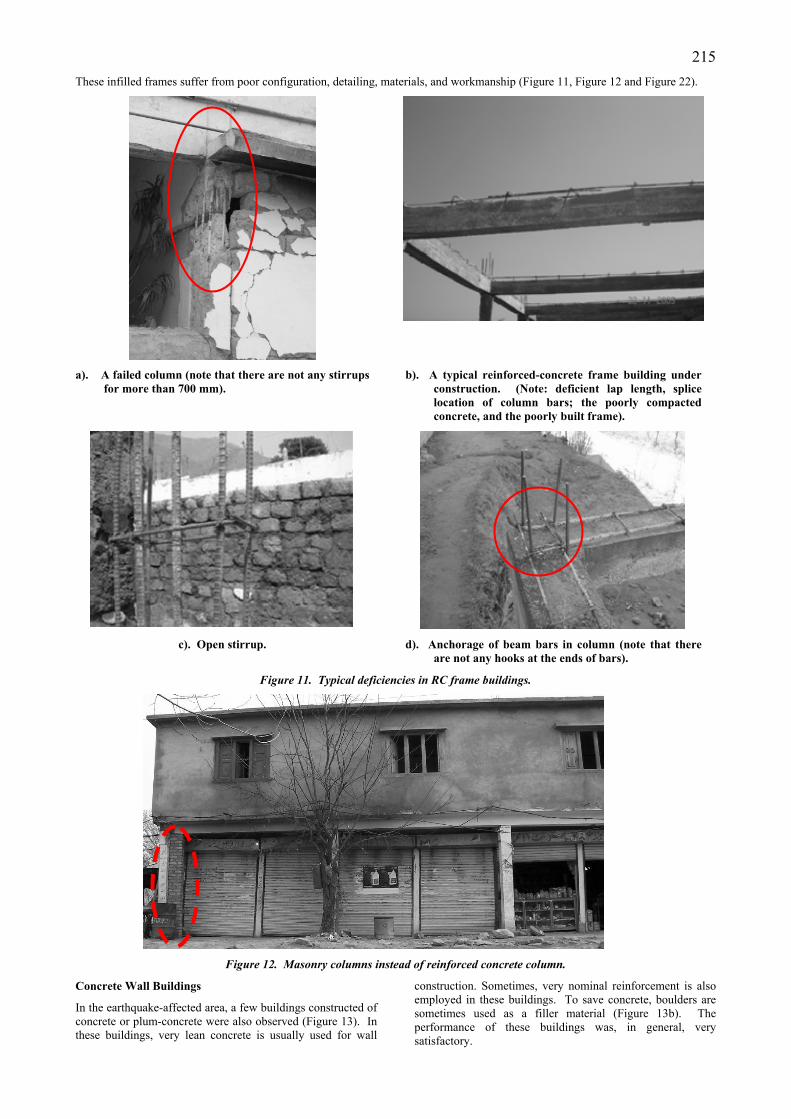
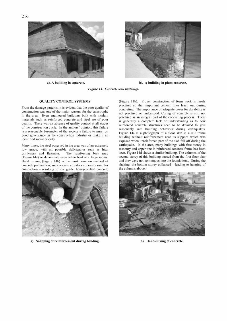
215These infilled frames suffer from poor configuration, detailing, materials, and workmanship (Figure 11, Figure 12 and Figure 22).
a). A failed column (note that there are not any stirrups for more than 700 mm).
b). A typical reinforced-concrete frame building under construction. (Note: deficient lap length, splice location of column bars; the poorly compacted concrete, and the poorly built frame).
c). Open stirrup. d). Anchorage of beam bars in column (note that there
are not any hooks at the ends of bars).
Figure 11. Typical deficiencies in RC frame buildings.
Figure 12. Masonry columns instead of reinforced concrete column.
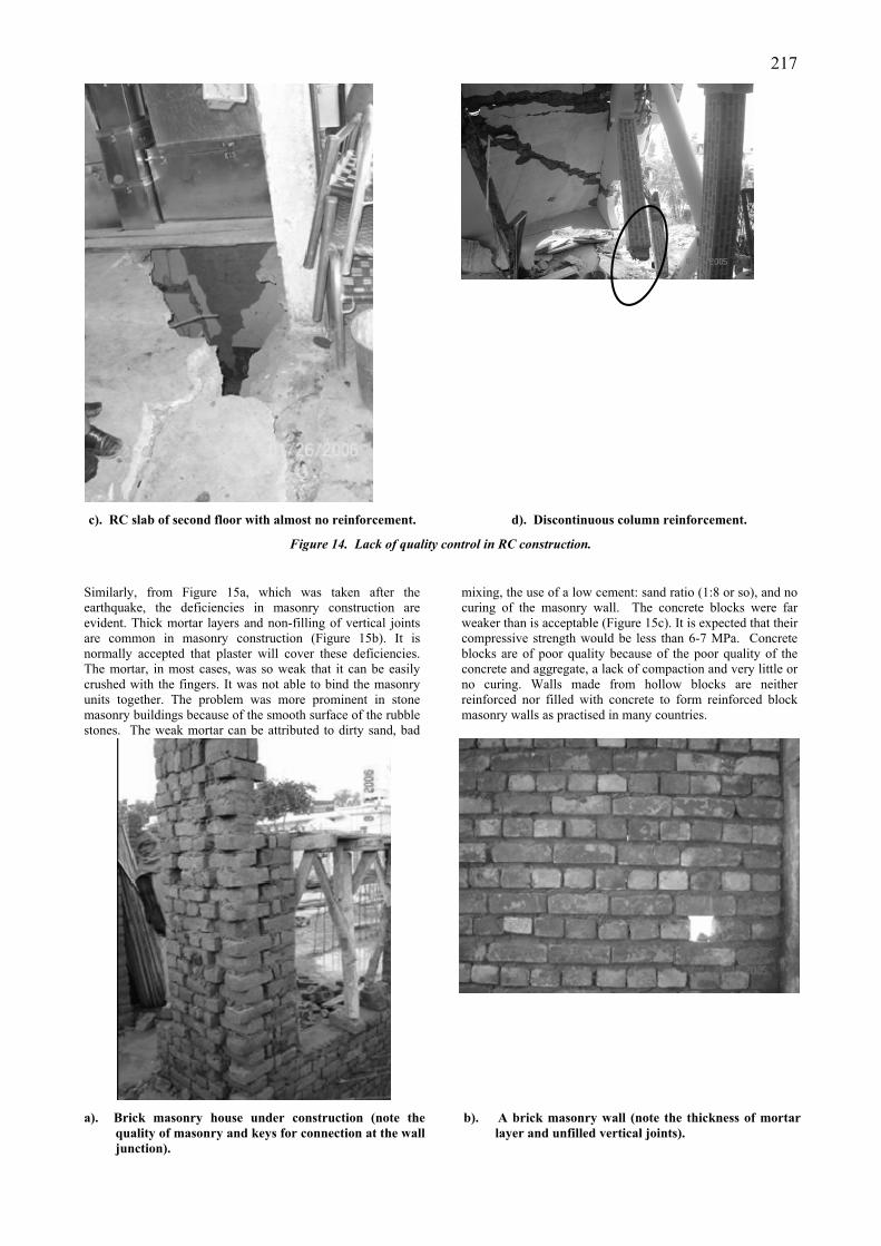
Concrete Wall Buildings
In the earthquake-affected area, a few buildings constructed of concrete or plum-concrete were also observed (Figure 13). In these buildings, very lean concrete is usually used for wall
construction. Sometimes, very nominal reinforcement is also employed in these buildings. To save concrete, boulders are sometimes used as a filler material (Figure 13b). The performance of these buildings was, in general, very satisfactory.
216
a). A building in concrete. b). A building in plum concrete.
Figure 13. Concrete wall buildings.
QUALITY CONTROL SYSTEMS
From the damage patterns, it is evident that the poor quality of construction was one of the major reasons for the catastrophe in the area. Even engineered buildings built with modern materials such as reinforced concrete and steel are of poor quality. There was an absence of quality control at all stages of the construction cycle. In the authors’ opinion, this failure is a reasonable barometer of the society’s failure to insist on good governance in the construction industry or make it an identified social priority.
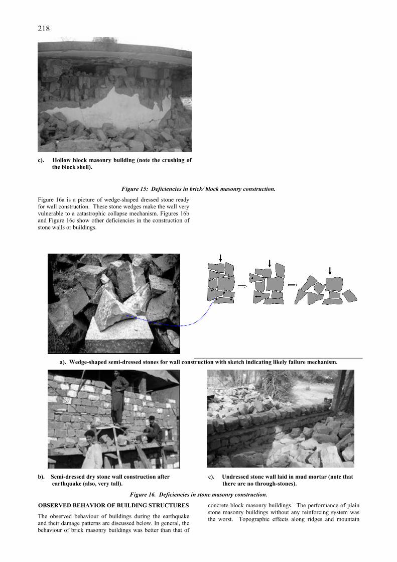
Many times, the steel observed in the area was of an extremely low grade, with all possible deficiencies such as high brittleness and flakiness. The reinforcing bars snap (Figure 14a) or delaminate even when bent at a large radius. Hand mixing (Figure 14b) is the most common method of concrete preparation, and concrete vibrators are rarely used for compaction – resulting in low grade, honeycombed concrete
(Figure 11b). Proper construction of form work is rarely practised so that important cement fines leach out during concreting. The importance of adequate cover for durability is not practised or understood. Curing of concrete is still not practised as an integral part of the concreting process. There is generally a complete lack of understanding as to how reinforced concrete structures need to be detailed to give reasonably safe building behaviour during earthquakes. Figure 14c is a photograph of a floor slab in a RC frame building without reinforcement near its support, which was exposed when unreinforced part of the slab fell off during the earthquake. In the area, many buildings with first storey in masonry and upper one in reinforced concrete frame has been seen. Figure 14d shows a similar building. The columns of the second storey of this building started from the first floor slab and they were not continuous into the foundations. During the shaking, the bottom storey collapsed - leading to hanging of the columns above.
a). Snapping of reinforcement during bending. b). Hand-mixing of concrete.
217
c). RC slab of second floor with almost no reinforcement. d). Discontinuous column reinforcement.
Figure 14. Lack of quality control in RC construction.
Similarly, from Figure 15a, which was taken after the earthquake, the deficiencies in masonry construction are evident. Thick mortar layers and non-filling of vertical joints are common in masonry construction (Figure 15b). It is normally accepted that plaster will cover these deficiencies. The mortar, in most cases, was so weak that it can be easily crushed with the fingers. It was not able to bind the masonry units together. The problem was more prominent in stone masonry buildings because of the smooth surface of the rubble stones. The weak mortar can be attributed to dirty sand, bad
mixing, the use of a low cement: sand ratio (1:8 or so), and no curing of the masonry wall. The concrete blocks were far weaker than is acceptable (Figure 15c). It is expected that their compressive strength would be less than 6-7 MPa. Concrete blocks are of poor quality because of the poor quality of the concrete and aggregate, a lack of compaction and very little or no curing. Walls made from hollow blocks are neither reinforced nor filled with concrete to form reinforced block masonry walls as practised in many countries.
a). Brick masonry house under construction (note the quality of masonry and keys for connection at the wall junction).
b). A brick masonry wall (note the thickness of mortar layer and unfilled vertical joints).
218
c). Hollow block masonry building (note the crushing of the block shell).
Figure 15: Deficiencies in brick/ block masonry construction.
Figure 16a is a picture of wedge-shaped dressed stone ready for wall construction. These stone wedges make the wall very vulnerable to a catastrophic collapse mechanism. Figures 16b and Figure 16c show other deficiencies in the construction of stone walls or buildings.
a). Wedge-shaped semi-dressed stones for wall construction with sketch indicating likely failure mechanism.
b). Semi-dressed dry stone wall construction after earthquake (also, very tall).
c). Undressed stone wall laid in mud mortar (note that there are no through-stones).
Figure 16. Deficiencies in stone masonry construction.
OBSERVED BEHAVIOR OF BUILDING STRUCTURES
The observed behaviour of buildings during the earthquake and their damage patterns are discussed below. In general, the behaviour of brick masonry buildings was better than that of
concrete block masonry buildings. The performance of plain stone masonry buildings without any reinforcing system was the worst. Topographic effects along ridges and mountain
219tops and soft soil sites showed in increased damage and destruction levels.
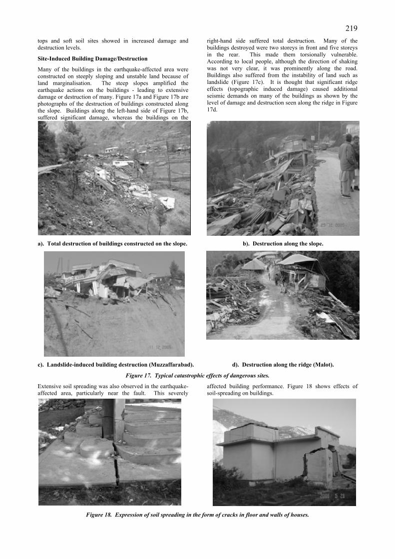
Site-Induced Building Damage/Destruction
Many of the buildings in the earthquake-affected area were constructed on steeply sloping and unstable land because of land marginalisation. The steep slopes amplified the earthquake actions on the buildings - leading to extensive damage or destruction of many. Figure 17a and Figure 17b are photographs of the destruction of buildings constructed along the slope. Buildings along the left-hand side of Figure 17b, suffered significant damage, whereas the buildings on the
right-hand side suffered total destruction. Many of the buildings destroyed were two storeys in front and five storeys in the rear. This made them torsionally vulnerable. According to local people, although the direction of shaking was not very clear, it was prominently along the road. Buildings also suffered from the instability of land such as landslide (Figure 17c). It is thought that significant ridge effects (topographic induced damage) caused additional seismic demands on many of the buildings as shown by the level of damage and destruction seen along the ridge in Figure 17d.
a). Total destruction of buildings constructed on the slope. b). Destruction along the slope.
c). Landslide-induced building destruction (Muzzaffarabad). d). Destruction along the ridge (Malot).
Figure 17. Typical catastrophic effects of dangerous sites.
Extensive soil spreading was also observed in the earthquake-affected area, particularly near the fault. This severely
affected building performance. Figure 18 shows effects of soil-spreading on buildings.
Figure 18. Expression of soil spreading in the form of cracks in floor and walls of houses.
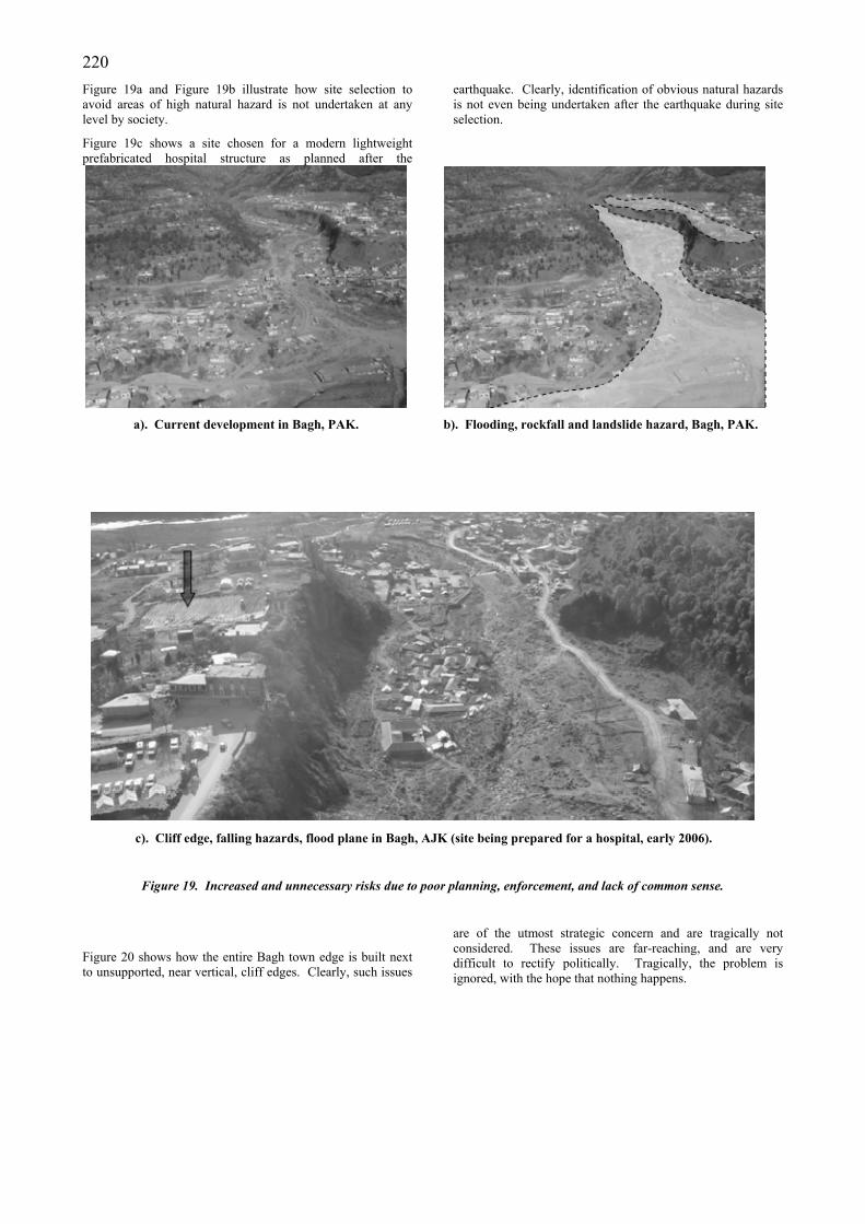
220 Figure 19a and Figure 19b illustrate how site selection to avoid areas of high natural hazard is not undertaken at any level by society.
Figure 19c shows a site chosen for a modern lightweight prefabricated hospital structure as planned after the
earthquake. Clearly, identification of obvious natural hazards is not even being undertaken after the earthquake during site selection.
a). Current development in Bagh, PAK.
b). Flooding, rockfall and landslide hazard, Bagh, PAK.
c). Cliff edge, falling hazards, flood plane in Bagh, AJK (site being prepared for a hospital, early 2006).
Figure 19. Increased and unnecessary risks due to poor planning, enforcement, and lack of common sense.
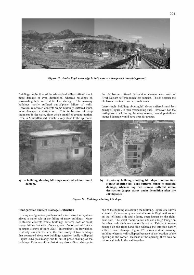
Figure 20 shows how the entire Bagh town edge is built next to unsupported, near vertical, cliff edges. Clearly, such issues
are of the utmost strategic concern and are tragically not considered. These issues are far-reaching, and are very difficult to rectify politically. Tragically, the problem is ignored, with the hope that nothing happens.
221
Figure 20. Entire Bagh town edge is built next to unsupported, unstable ground.
Buildings on the floor of the Abbottabad valley suffered much more damage or even destruction, whereas buildings on surrounding hills suffered far less damage. The masonry buildings mostly suffered out-of-plane failure of walls. However, reinforced concrete frame buildings suffered much more damage or destruction. This is because of deep sediments in the valley floor which amplified ground motion. Even in Muzzaffarabad, which is very close to the epicentre,
the old bazaar suffered destruction whereas areas west of River Neelam suffered much less damage. This is because the old bazaar is situated on deep sediments.
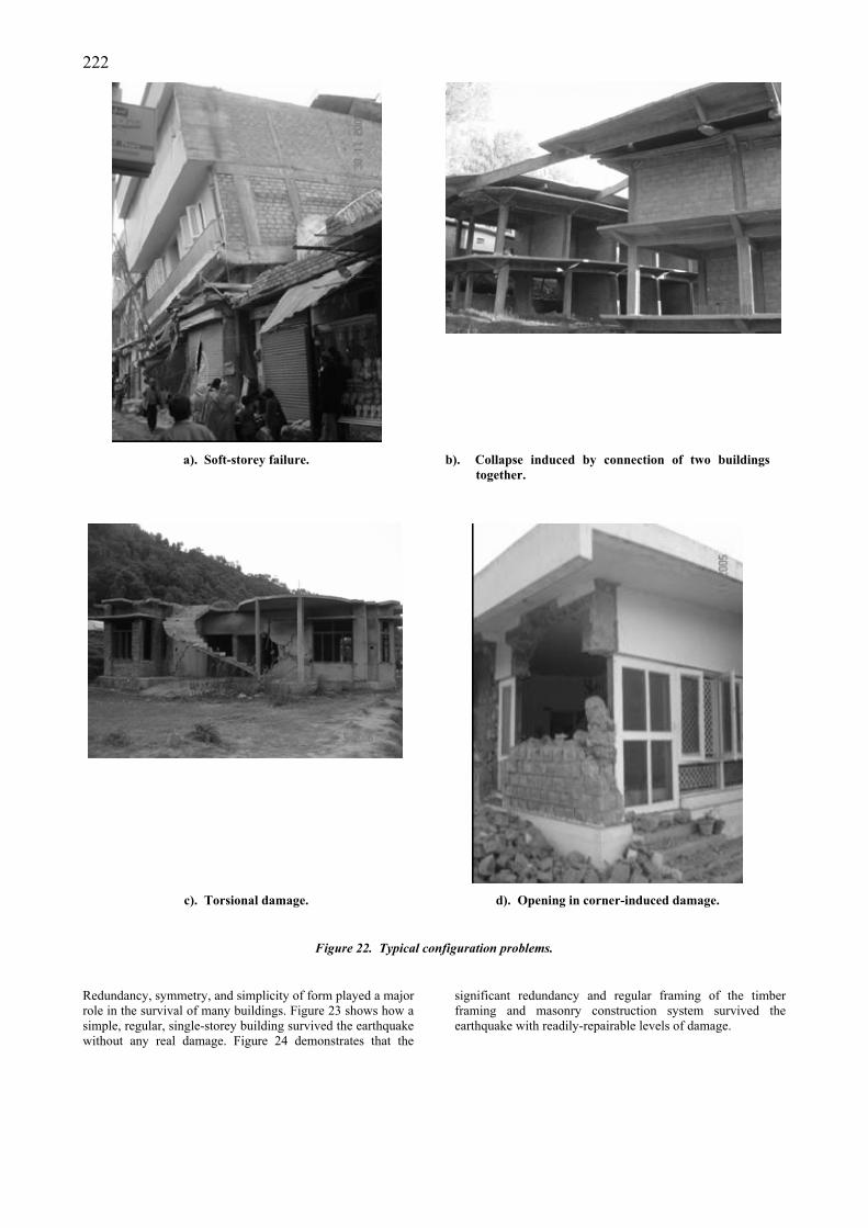
Interestingly, buildings abutting hill slopes suffered much less damage (Figure 21) than freestanding ones. However, had the earthquake struck during the rainy season, then slope-failure-induced damage would have been far greater.
a). A building abutting hill slope survived without much
damage. b). Six-storey building abutting hill slope, bottom four
storeys abutting hill slope suffered minor to medium damage, whereas top two storeys suffered severe destruction (upper storey under demolition after the earthquake).
Figure 21. Buildings abutting hill slope.
Configuration-Induced Damage/Destruction
Existing configuration problems and mixed structural systems played a major role in the failure of many buildings. Many reinforced concrete frame buildings suffered soft or weak storey failures because of open ground floors and infill walls in upper storeys (Figure 22a). Interestingly in Rawalakot, relatively less affected area, the third storey of two buildings that connected these two buildings together totally collapsed (Figure 22b) presumably due to out of phase shaking of the buildings. Columns of the first storey also suffered damage in
one of the building dislocating the building. Figure 22c shows a picture of a one-storey residential house in Bagh with rooms on the left-hand side and a large, open lounge on the right-hand side. The small rooms on one side and a large lounge on the other made the house torsionally active. This led to severe damage on the right hand side whereas the left side hardly suffered much damage. Figure 22d shows a stone masonry building where a wall collapsed because of the location of the opening in the corner. Because of the opening, there was no return wall to hold the wall together.
222
a). Soft-storey failure.
b). Collapse induced by connection of two buildings together.
c). Torsional damage. d). Opening in corner-induced damage.
Figure 22. Typical configuration problems.
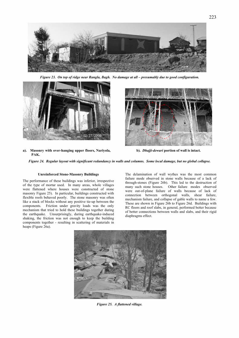
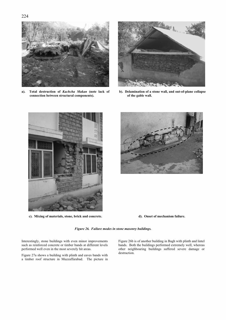
Redundancy, symmetry, and simplicity of form played a major role in the survival of many buildings. Figure 23 shows how a simple, regular, single-storey building survived the earthquake without any real damage. Figure 24 demonstrates that the
significant redundancy and regular framing of the timber framing and masonry construction system survived the earthquake with readily-repairable levels of damage.
223
Figure 23. On top of ridge near Rangla, Bagh. No damage at all – presumably due to good configuration.
a). Masonry with over-hanging upper floors, Nariyola,
PAK. b). Dhajji-dewari portion of wall is intact.
Figure 24. Regular layout with significant redundancy in walls and columns. Some local damage, but no global collapse.
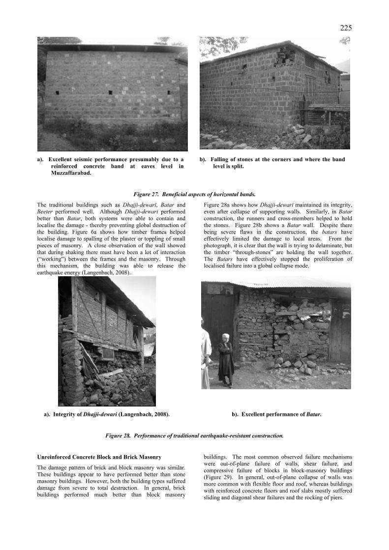
Unreinforced Stone-Masonry Buildings
The performance of these buildings was inferior, irrespective of the type of mortar used. In many areas, whole villages were flattened where houses were constructed of stone masonry Figure 25). In particular, buildings constructed with flexible roofs behaved poorly. The stone masonry was often like a stack of blocks without any positive tie-up between the components. Friction under gravity loads was the only mechanism that tried to hold these buildings together during the earthquake. Unsurprisingly, during earthquake-induced shaking, the friction was not enough to keep the building components together - resulting in scattering of materials in heaps (Figure 26a).
The delamination of wall wythes was the most common failure mode observed in stone walls because of a lack of through-stones (Figure 26b). This led to the destruction of many such stone houses. Other failure modes observed were out-of-plane failure of walls because of lack of connection between orthogonal walls, shear failure, mechanism failure, and collapse of gable walls to name a few. These are shown in Figure 26b to Figure 26d. Buildings with RC floors and roof slabs, in general, performed better because of better connections between walls and slabs, and their rigid diaphragms effect.
Figure 25. A flattened village.
224
a). Total destruction of Kachcha Makan (note lack of
connection between structural components).
b). Delamination of a stone wall, and out-of-plane collapse of the gable wall.
c). Mixing of materials, stone, brick and concrete. d). Onset of mechanism failure.
Figure 26. Failure modes in stone masonry buildings.
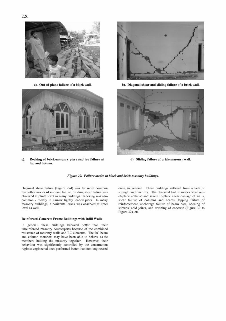
Interestingly, stone buildings with even minor improvements such as reinforced concrete or timber bands at different levels performed well even in the most severely hit areas.
Figure 27a shows a building with plinth and eaves bands with a timber roof structure in Muzzaffarabad. The picture in
Figure 26b is of another building in Bagh with plinth and lintel bands. Both the buildings performed extremely well, whereas other neighbouring buildings suffered severe damage or destruction.
225
a). Excellent seismic performance presumably due to a reinforced concrete band at eaves level in Muzzaffarabad.
b). Falling of stones at the corners and where the band level is split.
Figure 27. Beneficial aspects of horizontal bands.
The traditional buildings such as Dhajji-dewari, Batar and Beeter performed well. Although Dhajji-dewari performed better than Batar, both systems were able to contain and localise the damage - thereby preventing global destruction of the building. Figure 6a shows how timber frames helped localise damage to spalling of the plaster or toppling of small pieces of masonry. A close observation of the wall showed that during shaking there must have been a lot of interaction (“working”) between the frames and the masonry. Through this mechanism, the building was able to release the earthquake energy (Langenbach, 2008).
Figure 28a shows how Dhajji-dewari maintained its integrity, even after collapse of supporting walls. Similarly, in Batar construction, the runners and cross-members helped to hold the stones. Figure 28b shows a Batar wall. Despite there being severe flaws in the construction, the batars have effectively limited the damage to local areas. From the photograph, it is clear that the wall is trying to delaminate, but the timber “through-stones” are holding the wall together. The Batars have effectively stopped the proliferation of localised failure into a global collapse mode.
a). Integrity of Dhajji-dewari (Langenbach, 2008). b). Excellent performance of Batar.
Figure 28. Performance of traditional earthquake-resistant construction.
Unreinforced Concrete Block and Brick Masonry
The damage pattern of brick and block masonry was similar. These buildings appear to have performed better than stone masonry buildings. However, both the building types suffered damage from severe to total destruction. In general, brick buildings performed much better than block masonry
buildings. The most common observed failure mechanisms were out-of-plane failure of walls, shear failure, and compressive failure of blocks in block-masonry buildings (Figure 29). In general, out-of-plane collapse of walls was more common with flexible floor and roof, whereas buildings with reinforced concrete floors and roof slabs mostly suffered sliding and diagonal shear failures and the rocking of piers.
226
a). Out-of-plane failure of a block wall. b). Diagonal shear and sliding failure of a brick wall.
c). Rocking of brick-masonry piers and toe failure at
top and bottom. d). Sliding failure of brick-masonry wall.
Figure 29. Failure modes in block and brick-masonry buildings.
Diagonal shear failure (Figure 29d) was far more common than other modes of in-plane failure. Sliding shear failure was observed at plinth level in many buildings. Rocking was also common - mostly in narrow lightly loaded piers. In many masonry buildings, a horizontal crack was observed at lintel level as well.
Reinforced-Concrete Frame Buildings with Infill Walls
In general, these buildings behaved better than their unreinforced masonry counterparts because of the combined resistance of masonry walls and RC elements. The RC beam and column members may have been able to behave as tie members holding the masonry together. However, their behaviour was significantly controlled by the construction regime: engineered ones performed better than non-engineered
ones, in general. These buildings suffered from a lack of strength and ductility. The observed failure modes were out-of-plane collapse and severe in-plane shear damage of walls, shear failure of columns and beams, lapping failure of reinforcement, anchorage failure of beam bars, opening of stirrups, cold joints, and crushing of concrete (Figure 30 to Figure 32), etc.
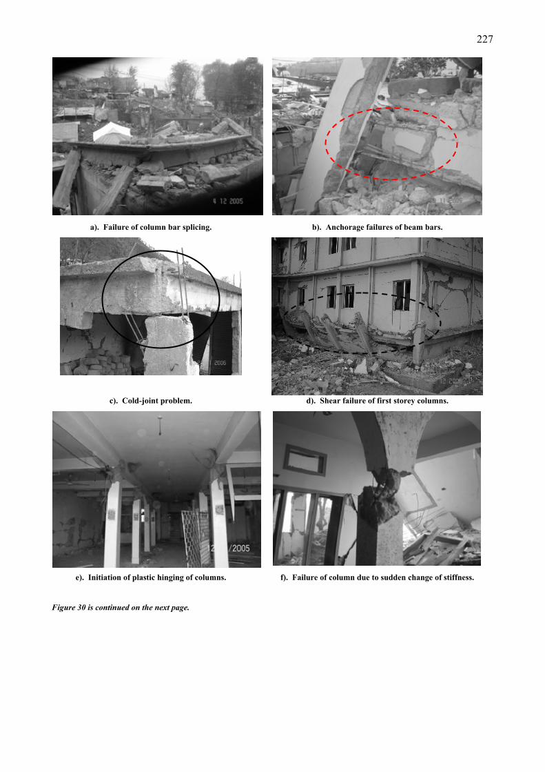
227
a). Failure of column bar splicing. b). Anchorage failures of beam bars.
c). Cold-joint problem. d). Shear failure of first storey columns.
e). Initiation of plastic hinging of columns.
Figure 30 is continued on the next page.
f). Failure of column due to sudden change of stiffness.
228
g). Deficient lap length, and very poor lap location leading to partial collapse of the building.
Figure 30. Typical RC frame failures.
Figure 31. Strong beams weak joint and columns.
Both, positive and negative performance of the masonry infills was observed. In many instances, these infills helped the building to survive (Figure 11 and Figure 32a). Once the infill walls collapsed, the RC members were unable to carry any gravity or further lateral earthquake loads, which led to the partial or total collapse of many of these buildings (Figure 30a). In other instances, these walls forced columns to fail in short-column mode (Figure 32b), or by shear failure of columns (Figure 32c).
229
a). Building being supported by infill walls after
failure of column. b) Short-column effect due to partial height masonry –
surprising that the bars have not fractured.
c). Failure of column due to shear forced by infill wall. d). Onset of development of soft-storey mechanism.
e). An infill wall on onset of out-of-plane failure in
RC frame building. f). Out-of-plane failure of masonry in RC frame
building.
Figure 32. Typical RC frame – infill wall interaction.
Figure 32d is a picture of a building where the top storey virtually suffered no damage, whereas most of the damage is concentrated in the second storey. It is on the onset of a soft-storey mechanism. Out-of-plane failures (Figure 32e and Figure 32f) were common because of a lack of connection between frame and wall.
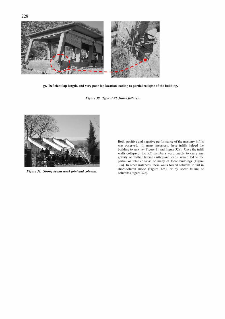
In addition to above discussed building types, a few timber buildings were also seen in the area. Seismic performance of these buildings was excellent; however, performance of few buildings was inferior. Figure 33 presents a photograph of such a building with heavy roof that suffered global instability due to lack of bracings.
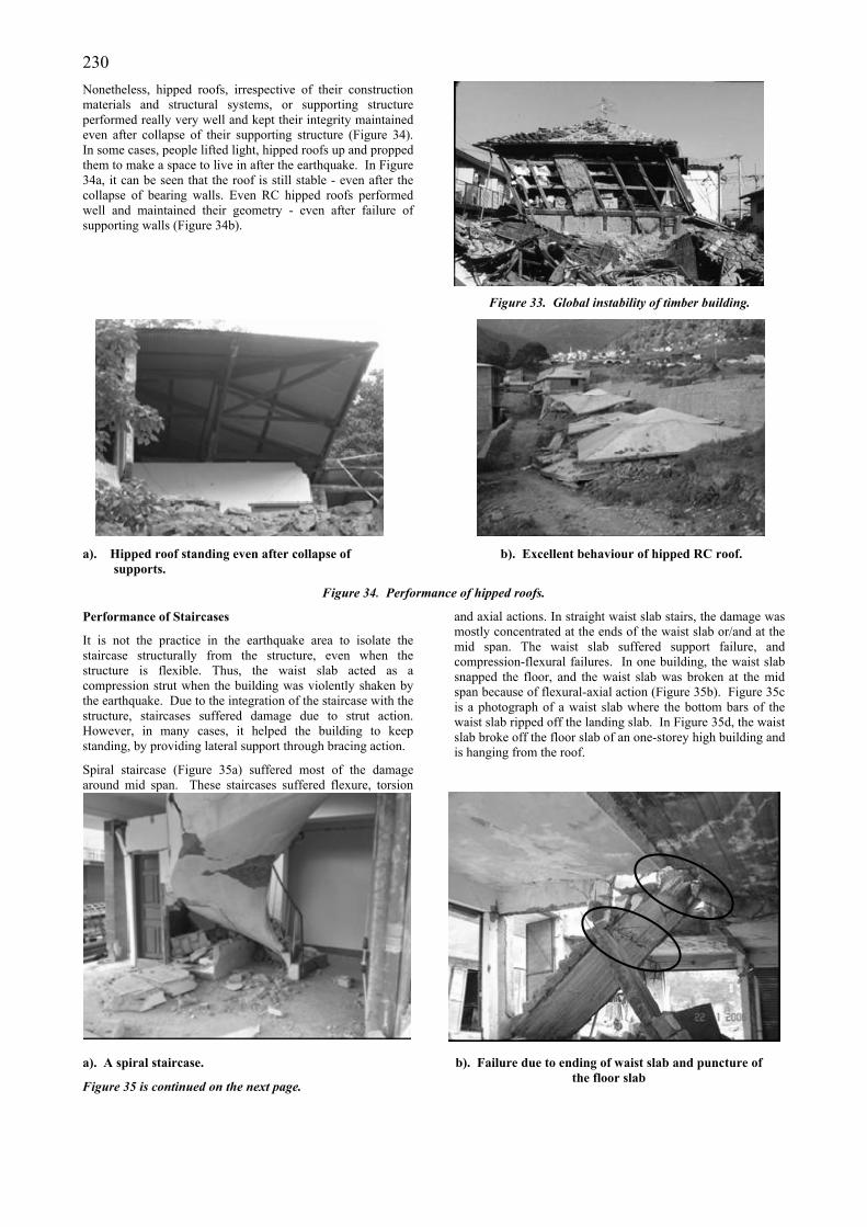
230 Nonetheless, hipped roofs, irrespective of their construction materials and structural systems, or supporting structure performed really very well and kept their integrity maintained even after collapse of their supporting structure (Figure 34). In some cases, people lifted light, hipped roofs up and propped them to make a space to live in after the earthquake. In Figure 34a, it can be seen that the roof is still stable - even after the collapse of bearing walls. Even RC hipped roofs performed well and maintained their geometry - even after failure of supporting walls (Figure 34b).
Figure 33. Global instability of timber building.
a). Hipped roof standing even after collapse of supports.
b). Excellent behaviour of hipped RC roof.
Figure 34. Performance of hipped roofs.
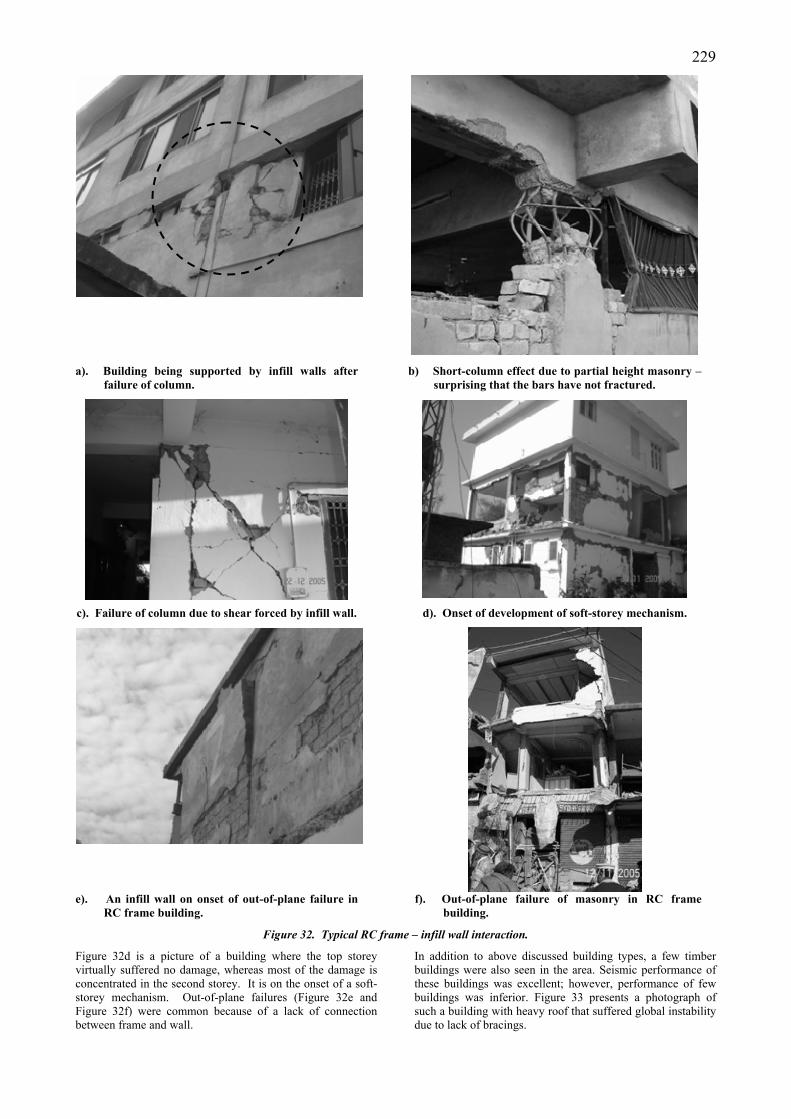
Performance of Staircases
It is not the practice in the earthquake area to isolate the staircase structurally from the structure, even when the structure is flexible. Thus, the waist slab acted as a compression strut when the building was violently shaken by the earthquake. Due to the integration of the staircase with the structure, staircases suffered damage due to strut action. However, in many cases, it helped the building to keep standing, by providing lateral support through bracing action.
Spiral staircase (Figure 35a) suffered most of the damage around mid span. These staircases suffered flexure, torsion
and axial actions. In straight waist slab stairs, the damage was mostly concentrated at the ends of the waist slab or/and at the mid span. The waist slab suffered support failure, and compression-flexural failures. In one building, the waist slab snapped the floor, and the waist slab was broken at the mid span because of flexural-axial action (Figure 35b). Figure 35c is a photograph of a waist slab where the bottom bars of the waist slab ripped off the landing slab. In Figure 35d, the waist slab broke off the floor slab of an one-storey high building and is hanging from the roof.
a). A spiral staircase.
Figure 35 is continued on the next page.
b). Failure due to ending of waist slab and puncture of the floor slab
231
c). Ripping off of the waist slab reinforcement.. d). Broken waist slab (hanging by reinforcement)
Figure 35. Typical staircase failures during an earthquake.
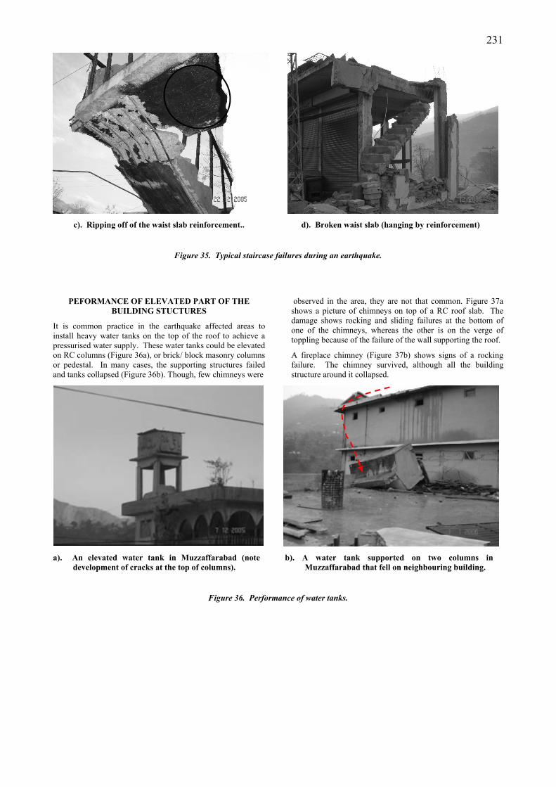
PEFORMANCE OF ELEVATED PART OF THE BUILDING STUCTURES
It is common practice in the earthquake affected areas to install heavy water tanks on the top of the roof to achieve a pressurised water supply. These water tanks could be elevated on RC columns (Figure 36a), or brick/ block masonry columns or pedestal. In many cases, the supporting structures failed and tanks collapsed (Figure 36b). Though, few chimneys were
observed in the area, they are not that common. Figure 37a shows a picture of chimneys on top of a RC roof slab. The damage shows rocking and sliding failures at the bottom of one of the chimneys, whereas the other is on the verge of toppling because of the failure of the wall supporting the roof.
A fireplace chimney (Figure 37b) shows signs of a rocking failure. The chimney survived, although all the building structure around it collapsed.
a). An elevated water tank in Muzzaffarabad (note development of cracks at the top of columns).
b). A water tank supported on two columns in Muzzaffarabad that fell on neighbouring building.
Figure 36. Performance of water tanks.
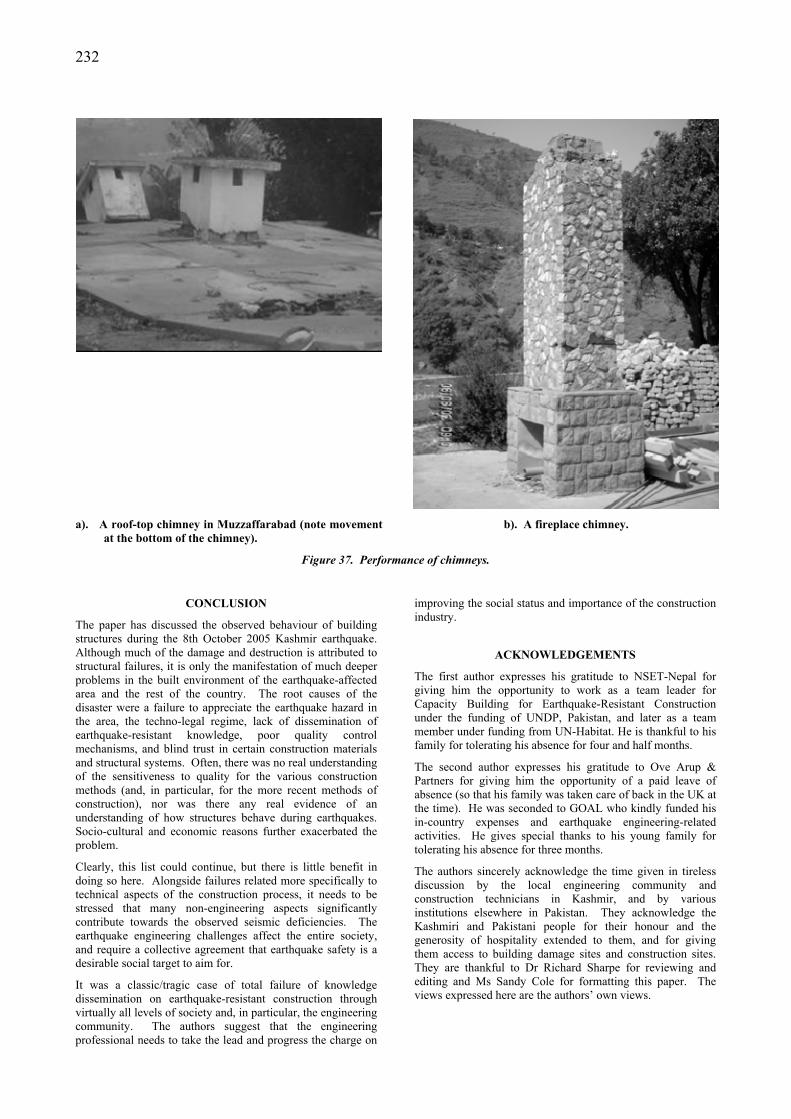
232
a). A roof-top chimney in Muzzaffarabad (note movement
at the bottom of the chimney). b). A fireplace chimney.
Figure 37. Performance of chimneys.
CONCLUSION
The paper has discussed the observed behaviour of building structures during the 8th October 2005 Kashmir earthquake. Although much of the damage and destruction is attributed to structural failures, it is only the manifestation of much deeper problems in the built environment of the earthquake-affected area and the rest of the country. The root causes of the disaster were a failure to appreciate the earthquake hazard in the area, the techno-legal regime, lack of dissemination of earthquake-resistant knowledge, poor quality control mechanisms, and blind trust in certain construction materials and structural systems. Often, there was no real understanding of the sensitiveness to quality for the various construction methods (and, in particular, for the more recent methods of construction), nor was there any real evidence of an understanding of how structures behave during earthquakes. Socio-cultural and economic reasons further exacerbated the problem.
Clearly, this list could continue, but there is little benefit in doing so here. Alongside failures related more specifically to technical aspects of the construction process, it needs to be stressed that many non-engineering aspects significantly contribute towards the observed seismic deficiencies. The earthquake engineering challenges affect the entire society, and require a collective agreement that earthquake safety is a desirable social target to aim for.
It was a classic/tragic case of total failure of knowledge dissemination on earthquake-resistant construction through virtually all levels of society and, in particular, the engineering community. The authors suggest that the engineering professional needs to take the lead and progress the charge on
improving the social status and importance of the construction industry.
ACKNOWLEDGEMENTS
The first author expresses his gratitude to NSET-Nepal for giving him the opportunity to work as a team leader for Capacity Building for Earthquake-Resistant Construction under the funding of UNDP, Pakistan, and later as a team member under funding from UN-Habitat. He is thankful to his family for tolerating his absence for four and half months.
The second author expresses his gratitude to Ove Arup & Partners for giving him the opportunity of a paid leave of absence (so that his family was taken care of back in the UK at the time). He was seconded to GOAL who kindly funded his in-country expenses and earthquake engineering-related activities. He gives special thanks to his young family for tolerating his absence for three months.
The authors sincerely acknowledge the time given in tireless discussion by the local engineering community and construction technicians in Kashmir, and by various institutions elsewhere in Pakistan. They acknowledge the Kashmiri and Pakistani people for their honour and the generosity of hospitality extended to them, and for giving them access to building damage sites and construction sites. They are thankful to Dr Richard Sharpe for reviewing and editing and Ms Sandy Cole for formatting this paper. The views expressed here are the authors’ own views.
233REFERENCES
Ambraseys, N. N., Douglas J., Sarma and Smith P. M. (2004). “Equation for the estimation of strong ground motions from shallow crustal earthquakes using data from Europe and the Middle East: Horizontal peak ground acceleration and spectral acceleration”. Bulletin of Earthquake Engineering. 3. pp 1-53.
Bilham, R. (2005). “The Kashmir Earthquake”, http://cires.colorado.edu/~bilham/Kashmir%202005.htm
Bilham, R., Gaur, V. K. and Molnar, P. (2001). “Himalayan Seismic Hazard”, Science, 293, pp 1442-4.
Bilham, R., Wallace, K. (2005). “Future Mw > 8 earthquakes in the Himalaya: implications from the 26 Dec 2004 Mw = 9.0 earthquake on India's eastern plate margin”, Geological Survey India, Supplement Pub. 85. pp 1-14.
ERRA, (2006). “Strategy Document Rural Housing Construction, Building Back Better: Rural Housing Reconstruction strategy of Earthquake hit districts in NWFP and AJK, Earthquake Reconstruction and Rehabilitation Authority, Pakistan”, www.erra.gov.pk/ report/Rural%20Housing%20final%20strategy-20%20Apr%202006
Jain, S. K. (2006). “The Road to Seismic Safety in the Subcontinent”, International Conference on 8 October
2005 Earthquake in Pakistan: Its Implications & Hazard Mitigation 18-19 January 2006, Islamabad
Langenbach, R, (2008). “Don’t Tear it Down”, (Manuscript), www.conservationtech.com
Langenbach, R. (2005). “Survey report on North Kashmir Earthquake of October 8, 2005, from the Indian Kashmir side of the line of control”, www.conservationtech.com
Mumtaz H., Mughal S. H. Stephenson M., Bothara J. K., (2008). “The Challenges of Reconstruction after the October 2005 Kashmir Earthquake”, Bulletin of the New Zealand Society for Earthquake Engineering, Vol. 41, No. 2, pp 68-82.
Mahajan, A. K., Kumar N and Aurora B. R. (2006). “Quick look isoseismal map of 8 October 2005 Kashmir earthquake”, Current Science, Vol. 91, No. 3, 10 August 2006.
Pararas-Carayannis, G. (2006). The earthquake of 8 October 2005 in Northern Pakistan, http://www.drgeorgepc.com/Earthquake2005Pakistan.html.
USGS. (2005). http://en.wikipedia.org/wiki/Image:8oct05_ sasia_quake_neic.jpg