Embed Size (px)
Citation preview

~
i
111
i
GENERAL INFORMATION THE PURPOSE OF THIS BOOK This instruction book is furnished so that the operator may learn of the characteristics of the plant A thorshyough study of the book will help the operator to keep the plant in good operating condition so that it will give efficient service An undershystanding of the plant will also assist the operator in determing the cause of trouble if it occurs
KEEP THIS BOOK HANDY Such simple mistakes as the use of imshyproper oil improper fuel or the neglect of routine servicing may reshysult in failure of the plant at a time when it is urgently needed It is suggested that this book be kept near the plant so that it may be refer- red to when necessary
SERVICE If trouble occurs and the operator is unable to determine the cause after a thorough study of this bookor if he is unable to deter- mine what repair parts are required needed information will be furshynished upon request WHEN ASKING FOR INFORMATION BE SURE TO TOSTATE THE MODEL SPEC AND SERIAL NUMBERS OF THE PLANT THIS INFORMATION IS ABSOLUTELY NECESSARY AND MAY BE OBTAINED FROM THE NAMEPLATE ON THE PLANT
MANUFACTURERS WARRANTY The manufacturer warrants each new engine or electric plant to be free from defects in material and workmanship Under normal use and service our obligation under this warranty is limited to the furnishing of any part without charge which within ninety (90) days after delivery to the original user shall be returned to us or our authorized service station with trans- portation charges prepaid and which our examination shall disclose tohave been defective
Our liability in ease of defective workmanship material or any costs incurred in remedying any claimed defective conshy
-dition in allY unit or sucll unU ~aving b4enrepairedaltered or which installatioriand service recommendatfonshave not been complied with is limited strictly to the proper adjustshyment authorized by the factory
This warranty does not include or cover standard accessories used such as carburetors magnetbs fuel pumpsetc made by other manufacturers Such accessories have separate warshyranties made by the respective manufacturers Repair or exchange of such accessories will be made by us on the basis of such warranties
This warranty is in lieu of all other warranties expressed or implied
IMPORTANT I
RETURN W ARRANTY CARD ATTACHED TO UNIT
LIST OF ILLUSTRATIONS
PAGE TITLE NO
Typical Installation bull bull bull bull bull Preface
Remote Control Stations bull ~ 10
Fuel Reservoir (day) Tank ~ bull bull 10
Lubrication bullbullbullbullbull ~ bull bull 11
Carburetor and Choke Adjustment bull bull 28
Governor Adjustment bull bullbullbull ~ bull bull 31
High Water Temperature Cutoff Switch bull ~ bull bull 31
Fan Belt Tension bullbullbullbull 32
Timing Gears ~ bull ~ bull ~ ~ 35
Tappet Adjustment bull ~ 35
Ignition Timing bullbull ~ bull bull 37
Piston Ring Gap bull bull 37
Piston Fitting bullbullbull 37
Bottom View of Engine bullbull 40
Alternating Current Generator Assembly 43
Care of Commutator and Brushesmiddot bull bull 43
i
0 ~ bullbullbull 0-0 bullbull ~ bullbullbullbullbull
bullbull bullbull 00 bullbullbullbull 0 bullbullbull
TABLE OF CONTENTS
SUBJECTI
Ii
Description Engine Details 0
Generator Details Control Equipment Details bull bullbullbullbull Installation
Location Ventilation bullbull Fuel Batteries ~ bullbullbullbullbullbullbullbull bull Connecting the Load Wires to Housed Plants bullbullbullbullbullbullbull Connecting the Load Wires to Unhoused Plants bullbullbullbullbullbull Remote Control Connections bullbullbullbullbull Fuel Reservoir (Day) Tank 0
Preparation Lubrication bullbullbullbullbull 0 bull bull bull bull bull bull bull bull bullbull
Fuel Radiator bull ~ bullbullbullbullbullbullbull bullbull Operation
Preliminary bullbullbullbullbullbullbullbull bullbullbullbullbullbullbullbullbullbull
starting the Plant Eleetrically bullbullbullbullbullbullbull Starting the Plant Manually bullbullbullbullbullbull bullbullbull ~ Checking the Operation bullbullbullbullbullbullbullbullbullbullbullbullbullbull
Cutoff SwitchEmergency)peration Stopping the Plant I Abnormal Operating Conditions
Low Temperatures bullbullbullbullbullbullbullbullbullbullbullbullbullbull High Temperatures bull bull bull bull bull bull bull bull bull bull Dust Or Dirt bullbullbullbullbullbull bullbull bull
Periodic Service Daily SerVice Weekly S~rvice bull 0 bullbullbullbullbullbullbullbullbullbullbullbullbullbullbullbullbull
Monthly Service bullbull 0 o Semi-Yearly Service bull 0 0 bullbull bullbull 0 bullbullbullbullbullbullbull 0 o bullbullbullbullbullbullbullbullbull 0
Adjustments C arburetor Chokemiddot 0 bullbullbull 0 bullbullbullbullbullbullbullbullbull 0 bull 0 bullbull bullbullbullbullbullbullbullbullbull ~
Governor ~ 0 bull e bullbull bull ~ bullbullbull Ii ii It lit co middot 0 - bullbull bull ~ ~
Speed Chart bullbullbullbullbull bullbull ~ 0
Voltage Chart bullbullbullbull lIigh Water Temperature Cutoff Switch ~ bullbullbullbullbullbullbullbull Fan Belt Tension bull ~ gt~ ~
Maintenance and Repair Engine bull Generator bull ~ bull ~ bullbullbull bullbullbullbull ~ Controls _ Trouble Shooting bullbullbullbull bullbullbullbullbullbullbull bullbullbull
Service Diagnosis POssible Cause - Remedy bullbull bullbull
Storing the Plant bull ~ bullbullbull
12 13
15 15 16 17 18
19 20 21
22 24 25
27 29 29 30 31 32
33 42
44 45
If EXHAUST LINE MUST BE PITCHED UPWA12D
bull CONSTPUCT A TRAPmiddot OF PIPE-FITTINGS
bull AT POINT OF RISE
EXHAIJST LINE PASSING CONDENSATION THROUGH WA11 TRAP OR PARTITION
Typical Onan Standby Installation THIS lNST ALLA TION IS A TYPICAL ONE BEFORE INSTALLING CHECK REGULATIONS
FIG 1middot
I
DESCRIPTION
This maliual is supplied to assist the operator in the proper installation and operation of the GO series of generating plants This manual covers both the AC (5GO) and DC (6GO) models Disregarding the instructions
given may lead to unnecessary trouble and expense
Each generating-plant is given an actual running test at the factory and is carefully checked under various electrical load conditions before shipshyment to assure that it is free of any defects and will produce its rated output Inspect the plant carefully for any damage which may have ocshycurred in shipment Any damaged part must be repaired or replaced before putting the plant into operation
These instructions apply to the standard modelS Some details may not apply to special models Some special equipment special installation reqUirements or special operating conditions may require the operator of this plant to modify these instructions However by using the inshystructions and recommendations given in this book asa general guide the operator should be able to make a good installation and to properly operate the plant Accessories and controls suitable for a normal in- stallation and according to the particular model are supplied as ordered
Should it become necessary to contact the factory or an Authorized Sershyvice Station in regard to this generating plant be sure to furnish the
nameplate information as shown This information must be known in order to properly identify the plant and to give proper advice
ENGINE PETAILS
A Continental Red Seal engine spec No Y91-273 or Y91-264 powers the plant The engine is a 4 cylinder L head 4 stroke cycle wafer cooled internal combustion type The cylinder bore is 2-78 the pisshyton stroke 3-12 compression ratio 6~ 1 to 1 and the maximum hOrse- power at 1800r p m is 23~ The engine speed is cQntrolled by acenshytrifugal flyweight type gear driven governor 12 volt starting and igshy
nition current is fUrnishedly two 6 volt batteries connected in serief5~ Charging current for the batteries is furnished by the generator on AC plants A separate automotive type battery charging generator is used on the DC plants Full length water jackets surround the cylinders and valve seats Circulation of the engine coolant is maintained by a belt driven ball bearing pump and the coolant temperature is thermostat controlled Thecooling system capacity is 11 quarts U S Measure~
A pusher type fan forces cooling air out through the front of the radiator A high water temperature cut-off switch (not on all models) stops the engine if the coolant temperature reaches adangerously high point A gear type oil pump supplies pressure lubrication to main camshaft and connecting rod bearings The crankcase oil capacity including the oil filter is4 quarts US Measure A fuel pump provides for connection to any appropriate gasoline fuel supply tank Some model plants are
ing
DESCRIPTION
equipped with a 5-12 gallonfueUank mounted inside the plant housing Other special model plants are equipped to burn gaseous fuel
I I
AC GENERATOR DETAILS
The alternating current generator isa revolving armature typedir~ctly connected to the rear of the engine The armature turns at crankshaft speed being supported aUhe engine end by the engine rear main bear-
A large ball bearing supports the outer end of the armature A series field winding is used for electrically cranking the engine The generator produces a small amoUnt Of direct current which is used for exciting the field and for charging the starting batteries Voltage and frequency are proportional to engine speed which is regulated by the engine governor~The 60 cycle plants operate at approximately 1800 r p m and the 50 cycle plants at approximately 1500 r p m The inshyherent design of the generator assures close regulation of voltage beshytween full load and no load conditions
DC GENERATOR DETAILS
The direct current generator is of the compound wound type anduses two interpoles for sparkless commutation The armature is suppor~ed at the engine end by the engme rear main beariilg and -at the outer end by a large ballbearing The generator is self excited and turns at engine speed The inherent design of the generator assures exceptionally close voltage regulation between full load and no load conditions
CONTROL EQUIPMENT DETAILS
The control equipment varies considerablywith differences inind1v1dshyual models The absence of various meters and automatic controldeshyvices on some models does not affect the efficiency of the plant but does impose upon the operator the responSibility of becoming familiar with the operation and performance of the plant so as to recognize any abnormal condition before damage occurs
3INST A L LATION
IMPORTANCE OF PROPER INSTALLATION - Proper installation is essential to satisfactshy
ory and dependable performance Location and ventilation are importshyant to consider in installation
LOCATION - The plant should be centrally located in relation to the electrical load If practicable install the plant in a
building or covered vehicle for protection from extremes in weather conditions
CAUTION
Exhaust gases are deadly poisonous and must be piped outshydoors if the Plant is installed indoors Excessive inhalashy
bulltion of exhaust gases may cause serious illness or death i Some engines have a small hole in the bottom of the exshy
haust manifold under the exhaust outlet for moisture to escape This hole may be plugged if exhaust gas escape is objectionable
The muffler outlet is threaded for 1-14 standard pipe Ifnecessary to run an exhaust line upward from the plant install a suitable conden sation trap at the lowest point in the line and drain it regularly Proshyper shielding must be provided if the exhaust line passes through an inshyflammable wall
If desired an underground muffler may be constructed Use a heavy 10 gallon or larger tank or drum welding suitable pipe fittings to the drumbull Use 1-14 pipe between the plant muffler and the underground mufflerbull Bury the underground muffler in loose gravel and see thatmiddot the bottom of the drum is perforated to allow condensation to drain out Extend the muffler outlet at least 24fabove ground and fitit with a pipe gooseneck
The site should be dry clean and middotweUventilated Either a damp or a dusty condition will require more frequent inspection and servicIng of the plant Allow at least 24 space on all sides for ease in servicing
If tbe plant is mounted aboard a truck or trailer see that ilismiddotfastenshyed securely when in transit and that it sets in a level pOSition when operating Housed Plant mounting holes are 18 apart lengthwise of the plant and 20-34 crOSSwise of the plant Unhoused Plant mounting holes are 17-14 apart lengthwise of the plant and 33 apart cross wise of the plant
VENTILATION Proper cooling depends upon correct ventilation to dissipate the heat generated by the engine and gen
erator Separate air inlet and outlet openings must be provided if the
INSTALLATIONmiddot
pIant is mounted in a small room or compartment
FUEL SuPPLY GASOLINE - The fuel pump inlet hasl8 pipe threads into which a fitting for 14
flared tubing is installed Be sure any fitting substituted has 18 male pipe threads to fit the fuel pump inlet Any tank used must be not more than 8 ft below the fuel pump Connections must be air tight to permit the fuel to reach the fuel pump Observe local fire code specifications in making the installation
NATURAL GAS OR VAPOR FUEL- Some special model plants are equipped to burn LPG or natural
gas fuel Any applicable gas codes must be complied with whenconshyneeting the plant to a source of gas fuel In some localities presence of foreign matter in the gas supply may require installation of a fuel filter in the fuel supply line bull The fuel inlet is threaded tor 34 pipe
NOTR
On natural gas installationsmiddottheatmospheric regulator on the plant is designed to operate on a line pressure not to exceed 4 to 6 ounces If the line pressure exceeds 4 to 6 ounces pressure it will be necessary to install a primary regulator in the line to reduce the pressure before it enters the atmospheric regulator
BATTERIES - Two 6-volt batteries (or one 12-volt) are required Use the short (6inch) jumper cable to connect the pos
itive (+)post of one battery to the negative (-rpost of the second batshytery connecting them in series for 12 volts For housed plants conshynect the battery cable which is attached to the start solenoid switch to
the remaining positive (+) post of the batteries Connect the grounded battery cable to the remaining negative (-) post of the batteries middotIt may be necessary to spread the positive cable clamp slightly to make it fit over the battery positive post Do not pound on the clamps to force them down on the posts Coat the clamps lightly with lightgrease or vaseline and tighten securely to the battery posts
For unhoused plants solderlessscrew typeterminals are provided inshyside the rear of the controlbox atop the generator Bring the battery cables in through the grommets at the rear of the control box Use care to connect the battery cables to the proper terminals as marked on the control box~Thenegative battery cable must connect to the grounded terminal post wide the control box
Batteries shipped dry must be prepared for use as directed on the tags attached to the batteries~ Batteries shipped ready for use were fully charged at time of shipment~ Such batteriesslowly lose their
5
INSTA LLATION
charge when standing idleand it may be found necessary to give them a freshening charge before putting them in use Use a hydrometer to determine the charge condition
CONNECTING THE LOAD WIRES TO HOUSED PLANTS
GENERAL - The AC output terminals are located behind the control panel on the fuel tank support Run the load wires
through the hole in the rear panel connecting them to the solderless connectors on the outputterminals Be sure to use the proper size insulated wiretaking into consideration the distance between the plant and the load and tM type of load Consult a competent electrician and observe applicable electrical codes in making the installation See that the main linemiddot is protected by a fused main switch or a cirellit bre akerbetween the load and the generator Refmiddoterto the plant wiring diagram and follow the applicable directions given below iorconnectshyiog the load wires
On 3 phase 4 wire plantstlle (line to neutral) single phase voltage will always be the lower voltage as specified onthe nameplate when the voltmeter (connected line to line)reads the higher voltage as specifiedmiddot on the nameplate
115 or 230 VOLT SINGLE PHASE 2 WIRE PLANT - Connect the white or grounshy
ded load wire to the gounded plant terminal Connectthe otherblack) load wire to the insulated plant terminal If the control panel bas a receptacle a load not to exceed 15 amps may be connected to each ~~
115230 VOLTSINGLE PHASE 3 WIRE PLANT- The centertershy minal is ground middot
ed For 115 volt current connect the white or grounded load wire to the center terminal and the other load wire to either of the two outside terminals AorB 2500 wattsareavialableoneachl15 volt~ircbit ground to A and ground to Bbull
--------230 V---------
---115v-------1J5V----~middot
For 230 volt current connect the load wires to the two outside insula- ted terminals A and B leaving the center terminalunused If the con-
INSTALLATION
------+---120V- 1+
trol panel has a receptacle a loadnotto exceed 15 amps 115 volts may be connected to each outlet
120 VOLT SINGLE PHASE208 VOLT THREE PHASE - 4 WffiE PLANT - The terminal farthest from the generator is grounded For
120 volt single phase current connect the grounded load wire to the grounded terminal and the other load wire toany one of the othermiddot three insulated terminalsAB or C For 208 volt 3 phase current connect a load wire to each of the three insulated terminals A B and C leaving the grounded terminal unused Reversing the connections between any two insulated terminals will reverse the direction of rotashytion of three phase motors Use a phase sequence indicator to assure in-phase connection
~--~----20BV-J~--------~
20BV-I--IIooofo_
r--------~r_-----~---120V-J
120V-IeP
For 208 volt single phase current connect one of the two load wires to each of any two trisulated terminals 1666 watts are available on each single phase circutt
If both single and three phase current is to be used at the same time use care not to overload any one circuit Subtact the amount of the 3 phase lead from the plant capacity Divide the remainder by 3 and this is theamount of load that may be taken from anyone circuit foz singlepbase current For example a 3 phase 2000 watt load ismiddotused This leaves 3 000 watts ~vailable Divide the 3 000 watts by 3 giving 1000 watts whiclr is the amount that is available from each of the 3 single phase circuits Do not attempt to take the entire 3000 watts in this example off one circuit as overloading the generator will reshysult
230 VOLT THREE PHASE 3 WIRE PLANT - Noterminalis groushynded Reversingthe
connections between any two of terminals AB or C will reverse the direction ofmiddot rotation of three phase motors Use a phase sequence in dicator to assure in-phase connection -230 volt single phase current may be obtained by connecting one load wire to each of any twoterminalso
INST A LLA TION
------230V-------
1666 watts are available on each single phase circuit If both single and three phase current is to be used at the same time follow the pri- nciples of load balancing as directed above for the 4 wire plant
CONNECTING THE LOAD WIRES TO UNHOUSED PLANTS
GENERAL - The generator output leads are within the small outlet box at the rear oflhe generatorbull Theloadwiresmay
be brought in through the desired knock-out hole of the box Loadwires must be of the proper size ofinsulated wire taking into consideration themiddot distance involved and the amount of the load The installatlon must meet requirements of electrical codes which apply in the localshyity bull Connections must be properly made and insulated Install an approved switch or other device for disconnecting the plant from the load Consult a licensed electrician if in doubt
On 3 phase 4 wire plants the (line to neutral) single phase VOltage will always be the lower voltage as specified on the nameplate when the voltmeter (connected middotline to line )reads the higher voltage as specified on the nameplant
UNHOUSED 115 VOLT or 230 VOLT SINGLE PHASE 2 wnm PLANT - Connect the white orgrounded load wire to the grounded
generator lead marked M2 Connect the other (black) loadmiddot wire tothe generator leadmiddotmarkedMl
UNHOUSED 115230 VOLT SINGLE PHASE aWIRE PLANT~ The genershy
ator lead marked M2 ilS grollnded~For 115 voltcurrentconnect the whiteormiddotgroUnded load wiretotheM2 lead and the (jther(placlt) load wire to either the M10r the Ma generator lead
v1 1 ~ ltlc
==========~====F===23jV~~ 1 2
25~O watts are availableoneach 115 volt circu~tM2to M1 01 M2to Ma For 230 volt current connect one load wire to the Mllead and the ather load wireJo the Mg lead leaving the M21ead unused TbuS 5000 watts of 230 volt current are available
8 INSTA LLA T ION
UNHOUSED 120 VOLT SINGLEPHASE208 VOLT THREE PHASEshy4 WIRE PLANT - The generator lead marked MO is grounded For
120 volt single phase current connect the white or grounded load wire to the generator lead marked Mo and the other (black) load wire to anyone of the other three generator leads marked M1 M2 or M3
Mo ~
M~ l -I
I 112
~ M3
--yyyyylt-J
~()Q-a$~()11 i- -~s ~
~~~Q~~~tJCJCJ~(j
Three separate 120 volt circuits are thus available Mo to M1 MO to M2 MO to M3- When using single phase current not more than one thrrd of the capacity of the generator is available on each of the three single phase circuits Divide the load as equally as possible between the three single phase circuits
For 208 volt single phase current the Mogenerator lead is notused Connect separate load wires to any two of the MV M2 or M3 generashytor leads_ Three separate single phase circuits are availatile Mr to M2 M1 to M3 and M2 to Ma As when connected for 120 volts the load should be divided between the three single phase circuits For 208 volt three phase current theMo generator lead is not used Conshynect the three load wires to the generator leads M1 M2 and ~3one load WIre to each generator hot lead Reversmg the connechonsooshytween any two leads will reverse the direction of rotation of 3 phase motors A phase sequence indicator may be used to assure in_phase connection when necessary_ If both single phase andthr~e phase curshyrent is used at the same time use care not to overload or unbalance
the generator Subhact the amount of the thteephase load from the total capacity of the generator Divide the remainder by three to deshytermine the amount of load which may be connected to each single phase circuit Refer to the ffhoused plant load connections for an example
UNHOUSED 220380 VOLT THREEPHASE 4 WIRE PLANT - The load
wires are connected to this plant the same as to the preceding120A08
INSTA LLATION
volt plant Fora 220 volt circuit use the connections for the 120 volt circmiddotuit For a 380 volt circuit use the connections shown for the 208 voltcirucit
UNHOUSED 230 VOLT THREE PHASE 3 WIRE PLANT - No genshyerator
lead is grounded For three phase currentconnect the three load wirestothe generator leads Ml M2and M3 one wire to each lead Reversing the connections between any two leads will reverse the dirshyectionof rotation of 3 phase motors
~ZI-_zltwr-_middotmiddot-lIrii j _---gt J
~ ~ ~ ~ ~ ~ ~ ~
ltgt C) C) ltgt
R3~ro~ for 230 volt single phase currentcorinecta separate load wire to each of any two generator leads Three separate single phase circuits are thus available~to M2M1toM3 and M2 toM3 Notmore tha~ one third of the generator capacity iSavaiIable on each single phase circuit
If both single and three phase current is used at the same time follow the principles of load distribution as directed for the 4 wire plant
REMOTE CQNTROL CONNECTIONS
A small four place terminal block is mounted in the unhoused plant control box or on thel10used plant fuel tank support To provide for remote control of starting and stopping the generating plant connect one or ijlore remote control switches to this terminal block If instalshyled within 85 feet of the plant use 18 wirebull Use 16 wire up to 135 feetbull Use 14 wire up to 215 feet or use 12 wire up to 350feet
The terminal block marked REMOTE CONTROL B+ 1 2 and3 appears in the illustration Terminal number 1 is used as a common ground terminal number 2 connects to the stopping circuit afthe plant and terminal number 3 connects to the starting circuit of thepIant The terminal marked B+ is to be used only with an automatic control installation
Connections for two styles of momentary contact toggle switcheS for use as Remote Start-Stop Stations are illustrated Connect all number 2or OFF switch terminals to the number 2 terminal on theplant terminal block Likewise connect together all number 3 or ON terminals and also all number I or single (not marked) terminals If the switch is to be mounted vertically start position should be up ward to conform with operational the plant when a toggle switch is used
STALLATION
REMOTE CONTROL TERMshy INAL BLOCK ATPLANT
TJYOSTYfpoundS OF MOMENTARY CONTACT SWITCH
FIG 2 - REMOTE CONTROL STATIONS
FUEL RESERVOm(DAY) TANK~ -In standby service the generating plantniay stand unused for many
days In this period of shut-down sufficient gasoline may evaporate from the carburetor to lower its fuel level considerably Prolonged cranking may then be necessary in order to pump enough gasoline futo the carburetor for the engine to-startbull On installations where automashytic unattended starting after extended shut down is necessary an aushyxiliary gravity feed fuel tankmiddot should be installed Fuel from this tank Ilows by graVity to the carburetor thus replacing any tuellost through evaporation and promotes quick starting after an idle period
INE TO CAR8vRETOR
FIGQ 3 - FUEL RESERVOIR TANK
ARMATURE B ENGINE STARTER CD~Cip~lan~tiS)~IampEbullbullbull-
IL HERE
KEEP OIL AT THIS LEVEL
OIL LEVEL GAUGE MARKS
AIR CLEANER
BATTERY CHARGE GENERATOR (DCPlants)
GOVERNOR CONTROL LINKAGE BALL JOINT
FIG 4 - LUBRICATION
PREPARATION12
PREPARATION FOR OPERATION~ - Before putting the plant in operashy tion it must be supplied with
fuel oil and water (or antifreeze llquid) Comply with the following instructions
LUBRICATION - Refer to Fig 4~ Use approximately 3 quarts (US Measure) ofa good quality heavy duty (detergent)
type oil to fill the crankcase to the high level mark on the bayonet type gaugebullApproximately 1 quart of oil remained in the oil filter when the crankcase was drained at the factory Do not use an oilheavier than SAE nurpber 20 in a plant being put into service the first time After the first oil change use an oil of the proper SAE number as indicated in the following table according to the lowest temperature to which the plant will be exposed when not running Temperatures indicated are for conditions where the plant will be standing idle long enough to cool to the surrounding temperature
LOWEST TEMPERATURE SAE NUMBER OF OIL
10QoF (Saoc) 40 S20 F (OoC) 30 OOF (-laoC) 20W Below OOF (-laoC) middot5W
See ABNORMALOPERATlNG CONDITIONS
The crankcase oil capacity is 3 quarts (U S Measure) plus approximshyately 1 quart used in the operation of theoU filter When a new oil filter element is installed it will be found that the element will absorb ~pproximately 1 quart of oiL
The useofa heavy duty (detergent)type oil will greatly increase the life of pistons and ringsbull If achange toa heavy dUty type oil is made after using non-detergent oil in this plant allow not more than onethird the usual operatinghouls between the next two oil changes Thereafter change the crankcase oil at the regular periods as recommended under PERIODIC SERVICE
CAUTION
Whenusing a detergent type Oil always use oil of the same brand when adding oil between changes When mixed together detergent oils of different manufacturersmiddot sometimes iotmchemical compounds that are harmful to internal engine parts
Keeptqe crankcase oil level at or near the upper leyel mark on the oil level gaUge but not above it If the crankcase is overfilled the conshy
PREPARATION
nectirig rods may strike the oil causing imprOper lubrication and ex(el3~ sive oil consumption Never allow the oil level to fall below the low level mark on the oil level gauge
Remove the air cleaner top andfill the cup to the level indicated with oil of the same SAE number as that used in the crankcase except as inshystructed under ABNORMAL OPERATING CONDITIONS - COLD TEMPshyERATURES
The ball jOints of the governor to carburetor control linkage will funcshytion best and have extended life when lubricated only with powdered graphite However if graphite is not available a light non-gummy lubricating oil should be applied
It is unnecessary to lubricate the generator bearing and water pump until time to do so as noted under PERIODIC SERVICE
FUEL GASOLINE - Use only a good grade clean fresh regular automotive type gasoline at least 68 octane rat shy
ing Do not use any highly leaded premium type of gasoline The use of any gasoline which has a high lead content will necessitate more freshyquent carbon removal spark plug and valve servicing However do not use a low octane gaSOline such as stove gas as its use will cause excessive detonation or spark knock and damage to engine bearshyings valves rings etc
If the plant has the mounted fuel tank do not fill the tank entirely full of cold gasoline as the fuel may expand as the plant warms up cau~ sing the gasoline to overflow Observe the usual precautions when handling gasoline Do not fill the tank when the plant is running
On plants equipped with the mounted fueltank note that the electric fuel gauge on the control panel registers the amount of fuel in the tank only when the plant is running If it is desired to check the fuel when the plant is stopped throw the ignition switch to the HAND START posishytion while making the observation Be sure to return the switch to the ELECT START position
If an auxiliary fuel tank is used connection may be made to the two way fuel shut-off valve at the bottom of the tank mounted on the plant
FUEL NATURAL GAS OR LPG - Make sure that fuel supply lines (and tanks if used) have been proshy
perly installed and connected
RADIATOR - The capacity of the cooling system is approximately 11 quarts (U S Measure) See that the radiator and cyl
inder block drain cocks are closed Fill the radiator with clean alkall
14 PREPARATION
free water such as clean rainwater The use of a rust and scale inhibishytor ls recommended If the plant will be exposed to freezing temperashytures use a standardantifreezein the proper proportion~ To avoid loss of anti-freeze through theoverIlow pipe due to expansion fill only to approximately 2 inches below the bottom of the filler neck Check the cooling system to see that there are no leaks
If the foregoing instructions have been carefully complied with the plant should be ready for operation However before starting the plant carefully study the paragraphs under the headings OPERATION and ABNORMAL OPERATING CONDITIONS immediately following
Important
II~GIVETHESE NUMBERS
WHpoundN ORDERING REPAI RPARTS OR REQUESTING SERVICE INFORMATION
rOR YOUR UNT J WRITE IN fIIUMBERS SHOWN ON P-LANTNAMEPLATpound
OPERATION
PRELIMINARY Be sure that the plant has been properly installed and prepared for operation before starting it Turn
onthe fuel supply and check for leaks correcting any that may be found See that the circuit breaker handle is in the OFF position so that no load is connected
CAUTION
If the preparation has been made for extremely cold weather using diluted No lOW oil the initial fill shying of the crankcase with diluted oil should have been left to be done immediately before starting the plant Be sure the crankcaSe is filled with the proper oil to the high level mark on the bayonet gauge bull
CHECK~HE OIL PRESSURE IMMEDIATELY AFTER STARTING esshypecially after the initial start (starting the plant for the firsttime after it has been installed or taken out of storage) Long storage periods may cause the oil pump to lose its prime making it necessary to poul oil into the pressure line preferably at the pressure relief valVe mecshyhanism
Oil was sprayed into the cylinders before the plant was shippedand it may be necessary to remove and clean the spark plugs ingasolinebeshyfore the engine will start the first time Dry the plugs before reinshystalling them
STARTING THE PLANT ELECTRICALLY - See thatthe ignition switch is set at themiddot
ELEC START position Ifmiddot the plant is to be operated on gasoline fuel press the START button firmly for several seconds to allow the fuel pump to become full and to pump gasoline into the carburetor The carburetor is automatically choked and the engine should start after a few seconds of cranking Hold the start button inuntil the plant has re achedrunrring speed If itdoes riotstartdonot presslheSTARTbtit shyton continuouSly but for periodS of not more than fiVEr seconds ata time with equivalent stops between If the plant fails to start after a few attempts check thefuel and ignition systems and repeal the proshycedure after correcting the trouble
If the plant is equipped for natural or Liquid Petroleum Gas operation see that the arm of the choke control mounted upon the exhaust manifold
is locked down so as to make the choke inoperative Nomiddotchoking is necshyessary when operating onmiddot gas and the carburetor choke valve should be wide open See tliat the gasoline supply is turned off and that there is no gasoline in the carburetor bowl Turn on the fuel supply and press the STARTbutton~ The regulatorprimet button at theltctmter Of the
regulator may have tobepJishedto start the engine the fUst time Do
16 OPERATION
notoverprime Unless the fuel to be used is of approximately the same BTU rating as that used by the manufacturer (1000 BTU) it will be necshyessary to readjust the carburetor gas adjustment valve to insure smooth and economical operation See the section headed ADJUSTMENTS
A closer spark plug electrode gap appears in the Table of Clearances as recommended to facilitate starting when operating with gaseous fuel
- - ~
STARTING THE PLANT MANUALLY - If gasoline fuel is used use the hand crank to turn the enshy
gine over enough times to fill the fuel pump and carburetor Throw the ignition switch to the HAND START position Crank the engine with a quick upward pull If the plant is equipped with the Sisson automatic choke have someone pull up on the automatic choke arm while crankshying Some plants are specially equipped with a low oil pressure ignishytion cut-off switch These special plants have a momentary contact toggle type switch located at the front of the plant This switch byshypasses the low oil pressure cut-off when in contact Hold this toggle switch in contact while manually cranking the engine and hold in conshytact until the plant has reached running speed If the plant is equipped with a manually operaJedchoke operate the choke as required by temshyperature conditions Do not spin the crank or press down on it If gas fuel is being used it may be necessary to press the regulator priming button at the center of the regulator to start the engine the first time Do notoverprime For manually starting a plant equipped for gas fuel the gas should have a BTU rating above 800 BTU per cu ft The temshyperature should be above 30o F (_loC) See that the automatic choke arm is locked down After the carburetor gas adjustment valve has been properly adjusted it should be unnecessary to use the priming buttonbull After the plant starts be sure to return the ignition switchto the ELECT START position
CAUTION
KEEP THE IGNITION SWITCH AT THE ELECT START POSITION AT ALL TIMES EXCEPT WHEN ACTUALLY STARTING THE PLANT MANUALLY THROW THE SWITCH TO THE HAND START POSITION WHILE CRANKshyING THE PLANT MANUALLYBUT RETURN IT TO THE ELECT START POSITION AS SOON AS THE PLANT STARTS bull
WHILE THIS SWITCH IS AT THE HAND START POSITION THE HIGH WATER TEMPERATURE CUT-OFF SWITCH (AND LOW OIL PRESSURE SWITCH IF THE PLANT IS SO EQUIPPED) IS CUT OUT OF THE CmCUlT AND THE PLANT IS NOT PROTECTED AGAINST OVERHEATING IF THE SWITCH IS LEFT AT THE HAND START POSITION WHEN THE PLANT IS NOT RUNNING THE BATTERY MAY BECOME DISCHARGED AND THE IGNITION COIL DAMAGED bull
OPERATION
If the plant will start but does not continue to run when electrically cranked possibly the start button is being released too soon If not try starting the plant manually If the plant starts and continues to run with the ignition switch at the HAND START position but stops when thrown to the ELECT START pOSition trouble is indicated in one of the relays the high water temperature switch or a loose connection
CHECKING THE OPERATION - After the plant starts allow the enshygine to reach operating temperature
Check the level of the coolant in the radiator as the thermostat may have allowed an air pocket to form thus preventing complete filling Add coolant to bring the level to the proper point if necessary The oil pressure should be between 20 and 40 pounds the coolant temperashyture approximately 1500 to 1800 F (650 to 820 C) and the battery charge rate between 2 and 7 amperes depending upon the charge conshydition of the batteries
When the plant is not in operation the water temperature gauge will register 2120 F The fuel gauge oil pressure gauge ~nd charge ammeshyter will register zero If it is desired to check the water temperature or fuel supply when the plant is not running throw the ignition switch to the HAND START pOSition while making the observation Besure to return the switch to the ELECT START pOSition after making the obshyservation While the plant is running the various gauges are automashytically in operation when the ignition switch is at the ELECT START position
Connect a load to the plant by throwing the main line switch or conshytrol panel circuitbreaker if the plant is so equipped to the ONposishytion The no load voltage is approximately 123 volts for the 115 volt plant after the plant has reached operating temperature The full loadvoltage is approximately 110 volts for a 115 volt plant Voltage will be correspondingly higher for plants of other voltages If the plant tends to surge or the voltage tends to fluctuate it is usually an indicashytion the engine needs additional warm-up before connecting a heavymiddot load ThOse plants which are equipped with the electrical meter panel have a circuit breaker which will automatically disconnect the load if the plant is severely overloaded~ If the plant is not equipped with the circuit breaker keep the correct size fuse in the load line switcbmiddot Those plants equippecentl with an output receptacle on the panel will not register on the meters any load which may be connected to thereceptshyacle This receptacle is provided for a trouble light or similar light load up to 15 amps 115 volts for each outlet
Continuous overloading of the generator will cause the generator temshyperature to rise to a dangerous point and lead to early failure of the windings If the main line fuse should blowout ortheplaIit circuit brlaker open remove the cause of overloading before again connectshy
18 OPERATION
ing the load to the plant On the three phase plant if part of the load is single phas~ the total load on any one leg should not exceed one third the total capacity of the generator On the 115230 volt plant divide the load as closely as possible between the two circuits when using 115 volt current Confine the load on each 115 volt circuit to not more than 2500 watts
HIGH WATER TEMPERATURE SWITCH - The high water temperature) switch is standard equipshy
men on the housed type of plant This switch is optional equipment on other models If the engine water temperature rises to a dangerous pOintthe cut-off switch operates to automatically close the stop circuit having the same effect as pressing the stop button on the plant The enshygine must cool off approximately lOaF before it can be restarted aftermiddot the cut-off switch has operated Before attempting to start the plant after the cut-off switch has operated determine and correct the cause of the high temperature
LOW OIL PRESSURE SWITCH - Some plants are equipped with a low oil pressure cut-off switch On these
plants if the engine oil pressure falls to approximately 6 pounds the cut-off switch operates to closethe stop circuit stopping the plant Deshytermine and correct the cause of the low oil pressure before attempting to again start the plant
EMERGENCY OPERATION If a burned out relay switch or other temporary difficulty prevents normal
operation of the plant with the ignition switch at the ELECT START pOSition the plant may be run temporarily with the switch at the HAND START position This is purely an emergency measure and should be resorted to onlyif necessary The starting batteries will not receive any charging current and all relays etc are cut out of the engine control circuit Keep a careful check on the plant while operating under these conditions
STOPPING THE PLANT - To stop the plant press the STOP switch momentarily The stop Circuit will not
work if the ignition switch is at the HAND START position In an emershygency if the stop circuit fails towork stop the plant by turning off the fuel supply
For
ABNORIVIALOPERATING CONDITIONS
LOW TEMPERATURES
Lubricationfuel and the cooling system require special attention at temperatures below 320 F (OoC)
CRANKCASE OIL - If the plant must be started after standing unused in temperatures between 320 F (OoC) and OOF
(_lSoC) use a good quality oil of SAE number 20Win the crankcase temperatures below OOF (-lSoC) use SAE number 5W oilbull The oil should be the detergent or heavy duty type
If number 5W oil is not obtainable dilute number lOW oil with apptoxishy
mately I part of kerosene t04 parts of oil Thoroughly mix the oil and kerosene just before pouring into the engine Immediately start the plant and run for at least 10 minutes to thoroughly circulate the mixtute through the engine Do not put diluted oil into the engine until ready to start the plant Mix the oil well just before pouringit into the engine Always use a mixture of the same proportions when adding oil between changes When using diluted oil changethe oil every 25 operating hours and check the oil level frequently bull Use undiluted oil again asspon as temperature conditions permit
CAUTION
Always drain the oil only when the engine is warm Drain the oil filter when changing to a lighter oil Add sufficient oil to compensate for that used to fill the oil filter
AIR CLEANER If congealed oil or frost formation within the air cleaner restricts the air flow remove and clean the
air cleaner Reassemble and use the air cleaner without oil until conshyditions permit the use Of oil in the normal mannerbull
COOLING SYSTEM - Themiddot coolant must be protected if there is any posshysibility of its freezing Use any good antifreeze
in the proportion recommended by the manufacturer for the lowest temshyperature to which the plant will be exposed The capacity of the cooling system is approximately 11 quartsbull
If the plant is to be stored in freezing temperatureswithout adding anti shyfreeze solution be sure to open the cylinder block drain cock to thorough ly drain aU water middotfrom the block after draining the radiator
If the water temperature gauge shows the engine to be operating too cool a portion of the radiator surface may be covered to raise the coolant temperaturemiddot to normal Avoid over heating~ Set the high water temper aturecut-off switch to operate at a temperature several degrees below
20 ABNORMAL OPERATING CONDITIONS
the boiling point of the coolant taking into consideration the altitude atmiddot which the plant is operating and the type of anti-freeze solution used
Check the anti-freeze solution frequently
FUEL GASOLINE - Use freSh clean high test (not highly leaded premium) gasoline for easy starting in cold weashy
ther bull Keep the fuel tank nearly full in order to prevent moisture conshydeIisatiQn within the tank which can cause considerable trouble from ice formation in the fuel system Do not fill the fuel tank entirely fuli of gasoline for expansion as the plant warms up may cause it to overshyflow
FUEL GAS OR VAPOR- Some types of Liquid Petroleum Gas will not vaporize readily at low temperatures Heat
exchanger equipment is available at extra cost and should be installed at the factory if temperature conditions require it
BATTERIES - Check the charge condition of the batteries frequently to be sure that they are kept in a fully charged condishy
tion A discharged battery will freeze at approximately 200F (_70C ) and be permanently damaged A fully charged battery will not freeze at -900F (-670C) Run the plant for at least 20 minutes after adding water to assure mixing the water with the electrolyte
HIGHmiddotTEMPERATURES
COOLING SYSTEM - If the plant is tobs operated in abnormally high temperatures (above 1000F or 3SoC) provide
sufficient air circulation for proper cooling Keep the cooling system cleap and free of rust and scale See that the high water temperature cut-off switch is correctly set and that the ignition switch is at the ELECT START position Keep the ignition timed correctly Keep the radiator well filled the fan belt tension properly adjusted and the crankcase oil level at but not above the upper level mark on the oil level gauge
CAUTION
For best cooling effects keep the door panels in place on the plant when it is in operation
Use SAE number 30 oil for temperatures up to lOOoF (3SoC ) and SAE number 40 for higher temperatures Check the oil level frequently and change the crankcase oil at least every 50 hours Keep the electshyrolyte level in the batteries up to normal
BATTERY - For a usual plantinstallaUon follow the instructions for Batteries under INSTALLATION If the installation
ABNORMA L OP ERATING CONDITIONS 21
agrees with the following description prepare the battery to assure long life by REDUCING BATTERY SPECIFIC GRAVITY
Standard automotive type storage batteries will self discharge very quickly when installed where ambient temperature is always above 900 F such as in a boiler room To lengthen battery life adjust the electshy
trolyte from a normal of 1 275 reading at full charge to a 1 225 readshying
The cranking power of the battery is also reduced when electrolyte is diluted to reduce acid activity and thus lengthen battery life If tempershyature is conSistently above 900 F (32 20 C) adjust the electrolyte as instructed below
1 Fully charge the battery DO NOT BRING AN OPEN FLAME OR BURNING CIGARETTE NEAR THE BATTERIES ON CHARGE BEshyCA USE THE GAS RELEASED DURING CHARGING IS VERY INshyFLAMMABLE
2 While battery is on charge use a hydrometer or filler bulb to siphon off all of the electrolyte above the plates in each cell Dont attempt to pour of0 I Dispose of the removed electrolyte AVOID SKIN OR CLOTIDNG CONTACT WITH ELECTROLYTE
3 Fill each cell with pure distilled water 4 Recharge the batteries for one hour ata 4 to 6 ampere rate 5 Use a reliable hydrometer to test each cell If the specificgravshy
ity is above 1 225 repeat steps number 2 3 and 4 until the highshyest specific gravity reading of the fully charged battery is not over 1 225 Most batteries require repeating steps 2 3 and 4 two times
DUST AND DIRTmiddot
Keep the plant as clean as practicable Service the air cleaner asfre quently as conditions require Keep the radiator flns clean and free of obstructions Keep the generator commutator and slip rings and brushes clean See that aU brushes ride freely in their holders Kecep oil and gasoline supplies in air tight containers Install a new oil filter eleshyment as often as necessary to keep the oil clean Change the crankcase oil more frequently if it becomes discolored before thenormal time has elapsed between changes
22 PERIODICmiddot SERVICE
GENERAL- Follow a definite schedule of inspection and servicing to assure better performance and longer life of the plant at
minimum expense Service periods outlined below are for normal sershyvice and average operating conditions For extreme load conditions or abnormal operating conditions service more frequently Keep a record of the hours of operation each day to assure servicing at the proper pershyiods
DAlLY SERVICE
If the plant is operated more than 8 hoUrs daily perform the DAILY SERVICE operations every8 hours
FUEL If the plant is operated on gasoline fuel check the fuel gaug~ often enough to assure amiddot continuous fuel supplymiddot Do not fill
the tank while the piantisrunning~
RADIATOR - Check the level of the coolant arid jf necessary add sufficient liquid 10 ~ing the level up to within one or
two inches of the bottom of the filler neck In freezing weather if a nonpermanent type anti-freeze is used check the protective strength of the coolant
AIR CLEANER - Check the oil level in the air cleaner cup and add sufficient oil to bring it10 the indlcated levelbull Clean
out and refill theoil cup ifdusty conditions prevail
CRANKCASE OILLEVEL- Check the oil level as indicated on the bay-net type oil level gauge Do not allow the
engine to operate with the oil level close to the low level mark on the gauge Add sufficient oil of the proper SAE number 10 bring the level 10the llpper level mark but do not overfill the crankcase
CLEANING - Keep the plant as clean as possible A clean plant will give longer and more satisfactory service
WEEKLY SERVICE
If the plant is operated more than 50 hours a week perform the WEEKLY SERVlCE operashytions every 50 hours
CRANKCASE OIL - Add crankcase oil as necessary or change the oil after 50 operating hours If the plant has been
operating with diluted oil change the oil after 25 hours operation
PERIODIC SERVIC E 23
GENERAL LUBRICATION - middotThe ball joint on the governor linkage will function best and have extended life if it U
lubricated only with powdered graphite However if graphite is not avshyailable a light non-gummy lubricating oil should be applied
Fill the distributor oil cup Put several drops of oil in the oil holes at each end of the battery charging generator and in the oil hole at the forward end of the starting motor of the direct current battery ignitionplane
Am CLEANER - Clean the air cleaner fUterelement and cup thorougshy hly in gasoline or other suitable solvent Allow to
dry or use compressed air to dry Refill the cup to the indicated level with clean oil of the same SAEnumber as that used in the crankcase except as noted under ABNO~MALOPERATING CONDITIONS~
FAN BEmiddotLT- Check the fan belt tension Adlustto permit about 34 play when pressure is applied midway between tpe fan
and crankshaft pulleys See ADJUSTMENTS section~ Install an new belt jf the old one is badly worn
BATTERIES - See that battery connections are clean and tight Keep the electrolyte level at the proper level above the plates
by adding only clean water which has been approved for use in batteries In freezing weather run the plant at least 20 minutes after adding water to mix the water with the electrolyte
SPARKPLUGS- Gleanthesparkplugsand checkthe electrodes gap Keep the gap adjusted toO 025for gaspline operashy
tion or at O 018 gap for gaseous fuel operation More frequent spark plug service may be necessary if leaded gasoline is used
WATER PUMP LUBRICATION - The water pump on only those plants built prior to model Spec J require
future lubrication Use a good grade of water pump gr~asein the water pumpgrease cupbull Turn the grease cup capdown 1 turn lteaCh 50 hours of operation If grease appears in the coolant thewaterpumpisbeing overlubricated To correct turn the CaP downless than 1 turn
DISTRIBUTOR - Check the distributor contact points Jftlleyare()nly slightly burned or pitted remove and middotrestirfacethem
on a fine stone Install new contact points if the old ones are badly burned Keep the gap adjusted to O 020 Excessive burning or pittiIlg of the points indicates aiaulty condenser which should be replacedwtth a new one
24 PERIODIC SERVIC E
MONTHLY SERVICE
If the plant is operated more than 200 hours a month perform the MONTHLY SERVICE operations every 200 hours
FUEL SYSTEM ~ Remove the pipe plug at the bottom of the carburetor and drain the carburetor of any sedimerit which may
have accumulated
Remove the cover and filter screen from the fuel pump Clean the screen thoroughly Reassemble the screen and cover Be sure the coshyver gasket is in good condition Be sure there are rio leaks at any point in the fuel system
DISTRIBUTOR - Place one drop of light oil on the distributor breaker arm pivot pin several drops on the felt pad under the
rotor and three or four drops on the flyweight mechanism distributed where it will reach friction points Place a light coating of grease on each cam lobe where the breaker arm block rubs
EXHAUST SYSTEM - Inspect all exhaust connections carefully Make any necessary repairs
COOLING SYSTEM - IIi some localitiespresence of lime or mineral deposits in the water may necessitate frequent
flushing of the plant cooling system Remove the top and bottom radishyator hoses If available connect a source of water under pressure to the bottom of the radiator and reverse ilushuntil the water runs clear from the top radiator connection Repeat the operation on the engine reversing the usual flow by running the water in at the outlet elbow Make Sure hose connections are tight when refilling the cooling system OIL FILTER - It is normal for detergent type crankcaSe oil to beshy
come discolored in usebull Intervals of filter element renewal must be determined by hours of operation operating condi- tions and engine condition rather than by oil discoloration when using detergent type oils IIistallation of a new filter element should coinshycide with an oil change Clean out the oil filter and install anew element The new filter ~lement will absorb approximately one quart of oil when the plant is started up After a short running period stop the plant and check the crankcase oil level Add oil as necessary to bring the oil up to the proper level
ENGINE COMPRESSION -Check the compression of each cylinder using a compression gauge Compression
of a new engirie when hand cranked is approximately 70 pounds A difshyference of more than 10 pounds pressure between cylinders indicates a compreSSion loss which should be corrected High compreSSion is an indication of excessive carbon or lead deposits in the combustion cham bers
25
PERIODIC SERVICE
CARBON REMOVAL - The frequency of necessary carbon and lead reshymovalservicing will vary with the typemiddotoffuel
used When a highly leaded gasoline is used it may be necessary to remove lead deposits more frequently than every 200 operating hours Remove the cylinder head and clean all carbon and lead deposits from the tops of pistons valves and top surface of the cylinder block Clean the deposits from the cylinder head If necessary grind the valves to a good seat
GENERATOR - Check the condition of the commutator collectorrings~ and brushes In service the commutator and collecshy
tor rings acquire aglossy brown color which is anormal condition Do not attempt to maintain a bright metallic newly machined finish If the commutator or collector rings become heavily coated clean with a lint free cloth Slight roughness may be remedied by lightly sanding with 00 sandpaper Clean out all carbon and sandpaper dust
When brushes are worn so that the top oithe brush is below a point midshyway between the top and bottom of the brush holder replace the brushes with newones~Brushes must ride freely in their holders and spring tenSion should be uniform Commutator brush spring tenSion is approxishymately 30 oz and collector ring brush spring tension is apprOximately 16 oz Tension should be measured with the free end of the spring level with the top edge of the brush holder
Gheck the brush rig for proper alignment of the reference marks on the brush rig and its s1lpport See Maintenance and Repair BrllSh Rig
GENERAL - Thoroughly inspect the plant for oil or water leaks loose electrical connections and loose bolts or nuts Make
any necessary repairs
SEMIYEARLY SERVICE Perform the foUoViingserv1ces periodically as specified i ~
GENE~ATOR BEARING -Remove the platefrOQl thehousingrear end I Thoroughly clean all dirt fromaround the
gener~tor bearing cover and remove the cover and gastet
LUbXi4late the generator b-all bearing at intervalS determined by the typ~of grease used Follow the paragraph of instructions below which agrees with the type of grease used Avoid mixing greases whenever practi~able
1 LilhiUmbaSe type bearing grease is used by and recommended by the factory This bearing grease is superior because it does not
run ard will not become hard or caked when used at temperatures
i
I
26 PERIODIC SERVIC E
ranging from minus 90oF to 12SoF bull With lithium base greaseservice the generator ball bearing each _5 000 operating hours or each 2 years Only a small q~tity of this grease need be used With a clean finger removeas mU(ili as possible of the old grease Force fresh grease iIito a 14 section of the bearing DO NOT fill the entire bearing Do not put a reserve of grease in the bearing recess nor in the bearing cover Q
IF dirt has gotten into the bearing remove the bearing and clean it in a good solvent Dry the bearing thoroughly and reinstall it
2 If ordinary good ball bearing grease is used service the generator ball bearing each 1200 operating hours or each 6 months With a
clean finger remove all the old lubricant and work approximately one tablespoonful of new bearing lubricant into the bearing Again clean out the bearing then refill about 12 full packing the lubricant well into the lower half of the bearing
Reinstall the bearing cover gasket and cover using care that no dirt gets into the bearing
ADJUSTMENTS
CARBURETOR GASOLINE - The carburetor should require no sershyvicing other thaIi keeping it clean and
free of sedimerit When cleaning jets and passages use compressed or a fine soft copper wire Be Sure that all gaskets are in their proshyper place whEln reassembling
Changes in the type of fuel used orin operating conditions may neces sitate a readjustment of the carburetor The main jet is not adjustable and its size has been selected to give the best performance The idle adjustment needle should be adjUsted to give the smoothest operation at no load Turn the idle adjustment needle out counterclockwise untn the engine begins to misfire then turn the needle in clockwise until the engine runs smoothly Adjust the throttle lever stop screw sothat there is 132 space between the screw end and the throttle stop when the plant is operating at no load
CARBURETOR GAS OR VAPOR - A change in the BTU rating of the fuel used will probably necessitate
readjusting the knurled head gas adjustment valve at the bottom of the carburetorbull With afuUloadon the plant turn the adjusting valve in (clockwise) until the voltage as shown on the AC voltmeter drops notice~ ably or the engine begins to lose speed Turn the screw slowly out (counterclockwise) until the voltage rises to normal and the engine runs smoothly If it is necessary to open the adjustment much beyond the point where normal voltage is attained in order to obtain smooth opera tion areadjustinent of the governor may be necessary Check the opshyeration at various loads There is no idle adjustment necessary for gas
or Butane-Propane vapor operation except to see that the throttle lever stop screw is adjusted to1 32 clearance between the screw end and the throttle stop with the plant operating at no load
ELECTRIC CHOKE - The choke was adjusted at the factory to operate ala temperature of 700 For 210 C In extremeshy
ly cold temperatures the choke may close so tightly that it willcause overchoking In extremely high temperatures a reverse situation may
occur To readjust this type of choke to function properly in very cold temperatures loosen the choke thermostat housing lockscrew and turn the thermostat housing slightly to the left (counterclockwise) To read~ just the choke for very high temperatures turn the thermostat housing tothexighf (clockwise) Be sure to tighten the lockllcrew after making the adjustment
SISSON CHOKE~ - Some plants are equipped with the Sisson choke conshytrol mounted on the exhaust manifold This type
choke control sll~uld not reqUire seasonal adjustments but may be read~ justed in the following manner Turn the shaft of the control to theposshyition where a 332 diameter rod or nail may be passed down through the hole in the end of the shaft opposite the lever Engage the rod or
middotCHOKE LOCK
ltJlUTOMATIC CHOKE CONTR OL LEv ER MUST as lOCKpoundD DOWN AS SHOWN WHpound PI T ISTO BE OPERATED ON
GAS
CH9Kpound PLATt
ROTATE poundNTIRE
UTOMAilC CHOKE
URETOR
-~R~~=l~~IAAEs~~_o~~~ P1ANTS
ELECTRIC CHOKE
USED ON GASOLINE OPER ATED PLANTS ONLY
FIG 5 CARBURETOR AND CHOKE ADJUSTMENT
Proshy
middot ADJUSTMENTS
nail in the notch in the mounting flange of the control Loosen the lever clamp screw just enough to allow the lever to be turned slightly To
adjust the choke for a leaner mixture push the lever downward To adjust the choke for a richer mixture pull the lever upward Retighten the lever clamp screw and remove the rod from the hole in the shaft Check to see that there is no binding or sticking action
GOVERNOR - The governor controls the speed of the engine and therefore the voltage and frequency of the current
per governor adjustment may be made as follows referring to Fig 6 Use a voltmeter while making the adjustments If a voltmeter is not av ailable the speed should be checked with a tachometer
1 With the engine stopped and tenSion on the governor spring adjust the governor linkage length so that the carburetor throttle stop lever clears the stop pin by not less than 164 as shown
2 Start the plant and allow it to reach operating temperature
SPEED CHART FOR CHECKING GOVERNOR REGULATION
SPEED SPREAb (WITHrn RANGE) LIMITS
iSPEED RANGE PREFERREDmiddot LINlITS (Approx)
MAX Mrn MAXF L to N L Mm FOR ALL 15 60 CYCLE PLANTS
CYCLE--64 57 59-61 35
451770-1830 100RPM-+1920 1710
3549-51 15 50 CYCLE PLANTS
FOR ALL CYCLE---54 47
451470-1530 100RPM --+-1620 1410
FOR DmEeuroT CURRENT PLANTS RPM----2000 1800 1800 100 NONE
i
30 ADJUSTMENTS
VOLTAGE CHART FOR CHECKING GOVERNOR REGULATION
TYPE OF PLANT VOLTAGE LIMITS PREFERRED VOLTAGE
ALTERNATING CURRENT PLANTS MAX MIN N L F L bull
N L F L PHASE WIRE
115 1 2 123 110 120 112 230 1 2 246 220 240 224 115230 1 3 123 110 120 112 120208 3 4 132 115 124 117 230 3 a 246 220 240 224 460 3 3 492 440 480 448
115 DIRECT CURRENT 120 115 115 115 230 DIRECT CURRENT 240 230 230 230
oiL
aAdjust the speed to give the desired voltage With no electrical load (N L) connected adjust the speed screw to the point where the voltage is nearest the desired voltage as shown in the VOLTAGE CHART for the type of plant in question Apply a full load (F L ) to the plant and again check the voltage Be sure the voltage is safe for the load applied An excessive voltage drop from full load to no load necessitates a sensitivity adjustment
Engine speed as checked with a tachometer should be nearest to the preferred limits as shown in the SPEED CHART
4 If the plant tends to hunt alternately increase and decrease speed) under load conditions increase very slightly the distance between the eye of the sensitivity screw and its support For best regulashytion ~eepthe screw in as close as possible without causing hunting ANY CHANGE IN THE SETTING OF THESENSITIVITY SCREW WILL REQUIRE CORRECTING THESPEEIJ SCREW ADJUSTMENT
5 If hunting occurs at NO LOAD screw the small bumper screw in un~il the hunt is stopped but not far enough to increase the engine sPred CAUTION Be sure all load is removed when adjusting the bumper screw
Be sure that all lock nuts are tightened as adjustments are compleshyted The governor can not operate properly if there is any binding sticking or excessive looseness in the connecting linkage or carshyburetor throttle assembly A lean fuel minture or a cold engine ~aycausehunting If the voltage drop is excessive when a full load is applied and adjustments are correctly made it is possible that the engine is low on power and should be repaired as necessary
ADJUSTMENTS Car6unto
~rhjhngtffleSiop Lever ~~vfver
ThrOffle SfopPin bull
uow PROXTEL HTWEEN BETWEEN STOP PIN NO LEVER N
Bumper Sc yew---
WIRSHING GOVERNOR PIERCE GOVERNOR
FIG 6 - GOVERNOR ADJUSTMENT
HIGH WATER TEMPERATURE SWITCH -Thehigh water- tempel1ture switch operates to stop the
engine if the coolant temperature rises too high I This prevents overshyheating which could cause serious damage to thf engine parts The enshygine may be started again when the coolant temp~rature drops approxishymately lOoF The dial adjustment should be setto operate at a tempershyature several degrees below the boiling point of the coolant taking into consideration the altitude at which the plant is operating Lower the setting 30 F for each 1000 feet above sea level The dial was set at 20SoF at the factory Do not set the switch to tperate at too Iowa temshyperature or the engine may be stopped before i~ reaches normal operashyting temperature The switch wiP not operate ~ the i~ition switch is at the HAND START POSITION 1
FIG 7 - HIGH WATER TEMP CUTOFF SWITCH 1
32 ADJUSTMENTS
FAN BELT TENSION - The fan belt tension is regulated by the width of the fan pulley groove The front half of the
pulley turns on the hub By loosening the two lock bolts arid turning the front half of the pulley clockwise the pulley groove is narrowed and the belt tightened Turn the pulley counterclockwise to widen the pulley groove and lessen the belt tension Allow 34 play in the belt as shown in the illustration Fig 8 Too tight a belt will have a short life and cause excessive strain and wear on the water pump bearings A belt too loose will slip wear out rapidly and will result in inefficient coolshying Be sure that the adjustment lock screws are properly tightened Check these screws frequently even when no adjustment is necessary
FAN BELT TENSION
FIGi- 8 - FAN BELT TENSION
II Ii
III
II ill
II I
III iii
III I
I1
Ii
III i
III II
III
I III ii
I
MAINTENANCE AND REPAIR 33 I j
i GENERAL - Refermiddot to the SERVICE DIAGNOSIS section for assistance in locating and correcting troubles which may occur The
information in this section is intended to assist in properly maintainingI the eqUipment and in making repairs Should a major overhaul become necessary it is recommended that the plant be carefully checked and
all necessary repairs made by a competent mechanic who is thoroughly familiar with modern internal combustion engines and revolving arma-
I ture type generators Referto the TABLE OF CLEARANCES herein
ENGINE
TIMING GEARS - The crankshaft and camshaft timmg gears are keyshyed to their respective shafts The camshaft gear
is fastened with a large hexagon nut and locking washer Thegears may be removed with a gear puller Always install both gears new I
I when either needs replaCing never one only The crankshaft gear has
one tooth punch-marked which must mesh with the two teeth punchshymarked on the camshaft gear See the illustration TIMINGGEARS~
I I
TAPPET ADJUSTMENT - The tappet adjustments may be reached by removing the valve chamber cover The
I tappets are the adjustable screw type requiring three wrenches to adshy
justSee the illustration TAPPET ADJUSTMENT
Adjust the valves for each cylinder as follows Crank the engine by I hand until the intake valve opens and closes Both valves for that cyshyI linder will then be closed Intake valves are numbers 2 3 6 and 7 The
adjusting screw clearance should be set to 0012 for both the intake and exhaust valves On engines which have the Roto type exhaust
I valves set the exhaust valve tappet clearance to 0010 Make sure the lock nut on each adjusting screw is securely tightened after the adshyjustment is made Tappets set too close may cause burned or warped valves seats and scored tappets or camshaft lobes Make a final check with the engine running at idle speed
VALVE SERVICE -The proper seating of the valves is essential to good engine performance If anyone valve is
leakingservice all valves Each valve its guide piston top the cyshylinder head and the top surface of the cylinder block should be thoroughshyly cleaned of all carbon depOSits Replace with a new one any valve of which the stem is worn or the head is warped or badly burnedbull The in~ take valve face angle is 300 and the exhaust valve face angle is 450 bull
All old valves to be reused should be groundand assembled t~ tlleirorshyigiriaLseats Grind only enough to assure a perfect seal Besureto remove all traces of grindipg compound from valves and seats Lightly
oUthe valves and guides b~ore reassembly
34 MAINTENANCE AND REPAIR
On some engines the exhaust valves are of the Roto type each valve having a cap under the end of the valve stem which pushes up against the valve spring retaining washer permitting the valve to rotate slighshy
tly as it opens and closes When reassembling install the cap on the end of the valve stem before installing the spring retainer locks Note that the exhaust valve retainer locks have a slight taper The thinner edge of the lock must face upward Be sure two locks are installed on each valve stem The intake valve locks are the single pin type If the Roto exhaust valves are properly installed it will be possible to turn them in their guides when fully open which is not possible with the conventional type valves set the tappet clearancesmiddot after the valves have been reassembled in the engine When tightening the cylinder head nuts start at the center of the head and work outward and towards the ends After approximately 10 hours of operation again check the tappet clearshyances making any necessary adjustments bull
IGNlTION TlMING - See Fig 11 Set the distributor contact points to 0020n gap at full separation There are stamped
markings on the flywheel which can be seen by removing the small flyshywheel inspection hole cover on the right side of the engine Crank the enshygine over with the hand crank until the No 1 piston is coming up onthe compression stroke Slowly crank the englne until the flywheel mark IGN centers in the inspection hole At this pOintthe distributor rotor should point to the distributor cap tower for the No 1 spark plug wire and the distributor pOints should just separate If the rotor points to the tower for the No 4 spark plug wire it will be necessary to remove the distributor lift the drive shaft in the cylinder head and turn it one half turn Start the plant and allow it to reach operating temperature Test the spark advance by applying a full electrical load Slow the enshygine by pulling on the governor arm then release and allow the engine to suddenly accelerate There should be one or two pings or detonashytion knocks If no ping is heard advance the timing If a continuous ping is present retard the timing Advance or retard the spark timing as necessary by loosening the distributor clamp and turning the distrishybutor body slightly clockwiseltto advancemiddot or counterclockwiseto retard Retighten the clamp screw Keep the spark advanced as far as possible without causing a ping or detonation under normal running conditions
PISTON RING REPLACEMENT - The piston and connecting rod assemshyblies are removed from the tops of
the cylinders Check the cylinders for out of round tapered or scored condition Rebore for oversize pistons if necessary Any ridge worn at the top of the cylinder should be removed if not reboring
Two compression rings and one oil control ring are used on each piston Fit each ring to its individual cylinder checking the gap between the ring ends by placing the ring squarely in the cylinder in a position corshyresponding to the bottom of its travel See Fig 12 The correct gap is
35MAINTENANCE AND REPAIR
FIG 9 - TIMING GEARS
AI82
rJ) -=-~_~ __ 1 middoth~
ADJUST VALVE CLEARANCE WHILE 7 shy
PISTON IS AT fiRING POSITION ~gtW
FIG 10 - TAPPET ADJUSTMENT
36 MAINTENANCE AND REPAIR
from 007 to 017 for compressiop rings 008 to 016 for oil rings Do not use rings which require too much filing to obtain the correct gap If using the old pistons clean all ring grooves of carbon despoits and see that oil return holes are open See that each ring fits its groove proshyperly with 0001 to 00025clearance Rings of the tapered type will be markEd TOP or may be otherwise easily identified and this taper must be installed with the smaller diameter toward the closed end of the piston Fit the proper ring in each ring groove on the piston spacshying the gaps equally around the circumference of the piston and no gap directly in line with the piston pin
PISTON REPLACEMENT - If cylinders become badly worn tapered or scored rebore and hone to fit one of
the available oversizes in pistons Pistons are available in 010 020 030 040 bull 050 and 060 oversizes The pistons should be fitted to the cylinders to a clearance of 0015 measured with a 12 wide feeler gauge inserted between the piston and cylinder at a point half way between piston pinholes A pull of 5 to 10 pounds should be required to pull the feller gauge past the piston See Fig~13 Piston and connecting rod assemblies must be properly aligned before install shyation in the engine
CONNECTING RODS - The connecting rod lower end bearings are steel backed and readily replaceable When removshy
ing the connecting rods be sure to note the numbers on the rods and bearing caps and reassemble with the numbers toward the camshaft Connecting rods 1 and 3 are not interchangeable with rods 2 and 4 Ilor are the bearings Notches machined in the connecting rod halves act as retainers for matching ears stamped into the steel back of the bearshying shells or inserts This design locks the shells and prevents their turning in the rod~ If a shell becomes worn both shells for that rod should be discarded and new ones installed The shells are designed to give a clearance of bull 0002 to bull 0022 without any scraping or other fitting Under no condition should fitting ever be attempted by scrapshying or filing of thecaporupperhalf of the rod asihis would permanshyently ruin the rod Be sure that rods and caps as well as bearing shells are perfectly clean and free of oilwhen inserting the shells Oil on the back of the shell will prevent proper seating of the shell in the rod or cap Oil the crankshaft journal after the bearing shell has been firmly seated
The sides of the connectirig rod crank ends are not babbitt lined in this
enginebull The faces are steel and being exposed to the steel crankshaft it is of vital importance that the side play clearance of 0065 to 00105 be maintained When installing new pistons pins or connecting rods ~
be sure pistons and connecting rod assemblies are first properly alignshyed on an accurate aligning gauge
31
IGNITION MARKS ON FLYWHEEL
I -RAOIATOT ENO Of ENGINE--o-shy
FIG 11 - IGNITION TIMING
FIG 12 - PISTON RING GAP
~-middotGUGE
FIG 13 -PISTONFlTTlNG
38 MAINTENANCE AND REPAIR
MAIN BEARINGS The crankshaft main bearings are of the same type as the connecting rod bearings The upper and lowshy
er shells are made in pairs for each individual bearing but front censhyter and rear be~rings are not interchangeable as pairs The same genshyeral directions given for fitting the connecting rod bearings should be observed in fitting the main bearings The clearance when installed should be 002 to 0024 The rear face of the front mainmiddot bearing takes the end thrust of the crankshaft The crankshaft end play should be 004 to 006 and is regulated by a removable thrust collar just to the rear of the crankshaft gear together with a shim pack to the rear of this collar When servicing the crankshaft or any parts in connection with the shaft especially connectitlg rod and main bearings always be sure that all oil holes in the shaft are open and clean Note that one censhyter main bearing cap screw is shorter than the other bearing cap screws This shorter screw musLbe installed on the camshaft -side of the bearshying cap Use of one of the longer screws at this point will block the oil passager BEARING CAUTION Certain engines are equipped with MORAINE I
i DUREX-IOO main bearings and (or) connecting rod bearings After a few hours of operation the bearing becomes a leaden gray in color and develops minute carters almost cellular in appearance TIllS APPEARANCE IS A NATURAL CHARACTERISTIC OFTHlS TYPE BEARING AND IN NO WAY INDICATES FAILURE Reasons for necessary bearing replacement are Wear on bearings causing a noticeable drop in oil pressure Damaged bearings due to deep scratches or gouges Loss of babbitt overlaydue to lubrication failure overheating or other abnormal conditions Before replacing bearings clean them thoroughly but NEVER USE ABRASIVES which may become imbedded Improved performance is gained by this bearing
PlSTONPINS The hardened piston pins are selected in production to obtain a 00004 loose fit in connecting rod pin bushshy
ing and 1ight push fit in piston boss By heating the piston in hot water the pisteR pin can be pushed in by hand MaintaiD these clearances if necessary to fit oversizemiddot piston pins Pins are available in bull 003 bull 005 and010 oversizes When reinstalling old pistons be sure that they are installed in their original cylinder and in the same pOSition relashytive to the numbered side ofthe connecting rod When reassenibling make sure that the snap ring at either end of the pin is tightly in place
CAMSHAFT The camshaft is an alloy steel forging Provided that proper lubrication is supplied the camshaft and its
bearings should never require servicing The cams if cut by too close adjustment of the tappet clearance can be reconditioned by careful honshy
ing if not too badly damaged The camshaft bearings are bronze bushshyings which are line reamed after installation in th~ crankcase to a clearance of 002 to 004 for front and rear or bull 003 to 0045 for
39MAINTENANCE AND REPAIR
center bushings The installation of new camshaft bearings is not practicable without the proper line reaming equipmenL
WATER PUMP The water pump on engines PRIOR TO SPEC J are a centrifugal ball bearingself sealing type To
dismantle the pump proceed as follows~
1 Remove the nut and lockwasher from the front of the water pump shaft end using a suitable puller pull tre pulley oft the shaft
2 Remove the three nuts mounting the shaft support to the body and remove the support assembly
3 To remove the impeller remove the set screw and pull or press the impeller from the shaft Note that if the set screw is loosened only a few turns it will not be free from jj the hole in the shaft
4 To retpove the shaft and bearings from the support remove the set screw from the top of the support and press the assem bly out through the front
5The seal will be found assembled in the impeller h~~ Care must be taken in removing this assembly as the carbOn seal IS fragile and easily broken~ To reassemble reverse the procedure used in disassembly When reassembling the pump make sure that the set screw projects far enough to line up the impeller on the shaft Press the impeller on flush with the end of the shaft Pack the space between bearings with a good grade of waterpump grease bull
WATER PUMP (For Models Beginning with SPEC~J) -The water puinp on
this eurongine is a centrifugal self sealing prelubricated ballbearing type To dismantle the pump follow this procedure
1 Remove the water pump assembly from the engine
2 Remove the screwsthat hold the end plate on the back of the water Ptlmp assembiy
3 Use a suitable puller to remove the pulley from the impellershaft
4 Remove the lock ring that retains
the bearin~apound)he p~lley end~
5 Press the impeller shaft out of thebody castingf~om1hemiddot~~-of the water pump This frees the impellerbullbull t
40 MA~NTENANCE AND REPAIR
6 Tap the shaft seal out by inserting a plug through the front of the casting Tap out the seal gently to prevent any damage to the seal
7 Reverse the disassembly steps in order to assemble the pump Note that the impeller hub is assembled to the impeller shaft with the fins facing the water pump seal
CRANKCASE VENTILATION - The crankcase oil fill cap permits entry of air to the crankcase which is
drawn out through the valve chamber cover tube to the intake manifold If the oil fill cap becomes clogged with dust and dirt excessive crankshycase vacuum may build up causing oil to be drawn from the valve chamshyber into the intake manifold The baffle plate on the inner side of the valve cover must be in place and undamaged for proper ventilation
LUBRICA TION SYSTEM - A gear type oil pump supplies oil under ~ pressure through drilled passageways to the crankshaft main bearings lower connecting rod bearings cam- shaft bearings and valve tappets Wheneverthe engine is disassembled
I for servicing make sure that all oil passages are unobstructed i Thoroughly clean the engine oil pan and the oil pump strainer screen
An oil pressure relief adjustment is adjusted at the factory to give a pressure of 20-40 pounds at the governed speed with the engine oil hot The oil pressure relief adjustment is reached by removing a large he~agon shaped plug in the side of the crankcase just below the oil filter and adjusted by addirig or removing spacerwashers
I
FIG 14 - BOTTOM VIEW OF ENGINE
41MA INTENANCE AND REPAIRmiddot
TABLE OF CLEARANCES
NOTE
The clearances given below are for settings at 720 F (22 20 C)
MINIMUM MAXIMUM Valve Tappets - Roto Exhaust ~ 010 Valve Tappets - Intake and Exhaust (Conventional) 012 Valve Seat Width ~ Intake and Exhaust 116 332 Crankshaft Main Bearings bull 0002 0024 Crankshaft End Play 004 middot 006 ConnectingRoa Bearingmiddot 0002 bull 0022 ConnectingRod Side Play-(Desired 0065) 0065 middot 0105 Piston in Cylinder middot 0015 Camshaft Bearings - Front and Rear 002 bull 004 Camshaft Bearings - Center bull 003 bull 0045 Distributor Breaker Points Gap bull 020 Spark Plug Electrode Gap-For Gasoline Fuel bull 025
Spark Plug Electrode Gap-For Gaseous Fuel 018 Piston Compression Ring Gap 007 bull 017 Piston Oil Ring Gap 008 bull 016 Crankshaft Main Brg Journal- Std Size 1 7475 1 7485 Crankshaft Rod Brg Journal - Std Size 1 499 1 500
42 MAINTENANCE AND REPAIR
i
i
GENERATOR
GENERAL - The generator normally requires little maintenance other than the PERIODIC SERVICE
COMMUTATOR AND COLLECTOR RINGS -After a long period of servict the surface of
the commutator may become worn to such an extent as to cause the mica insulation between the commutator bars to extend above the level of the bars This condition would cause noisy brushes andmiddot would soon lead to excessive brushsparkingand pittingof the commshyutator bars High mica should be undercut toadepth equal to the distance between barsorapproximately 132 Lift each brush high in its guide so that its spring will press against its Side and remove the end bell Tag leads to insure correct replacementmiddot With a tool fashionedfrom a hack saw blade carefully undercut the mica Be
sure to remove any burrs which may have been formed when undershycutting and see that spaces between bars are completely free of any metallic particles
Should dusty operating conditions cansethe surface of the commutator orcoUector rings to become grooved out of round pitted or rough it will be necessary to remove the armature and turn the commutator or collector rings down in a lathe It will be necessary to remove the generator field frame before the armature can be removed Remove the ball bearing from the armature shaft before turning down to preshyvent any foreign material getting into it After the commutator is turneddownthe mica between bars must be undercut as described above When the armature is reinstalled align it as carefully as possible before installing the frame and end bellbull
BRUSH RIG - Itisnnnecessary to remove the brush rig from the end bellwheilserviclng the generator If it has been
removed mistakenly lineup the paint mark on the outer edge of the brush rig withthe mark on thebrnshrig support in theeIid belLmiddot Amiddot deviation from the proper positioning of the brush rig will lead to excessive arcing ofmiddot the brushes burning of the commutator low generator output and possible irreparable damage to the generator windings due to overheating Any defective condenser should be reshyplaced with a new one of the same capacity
BRUSHES - Install new brushes when the olqonesare worn so that the top of the brush is belaw a point midway between the
top and bottom of the brush guide Donot continue to use brushes that are worn too short because the spring tension lessens as the brush
becomes shorter and weak spring tension leads to exceSSive brush sparking and pitting of the commutator or collector rings It is recshy
ommended that only a moderate load be applied to the generator until
PLVWHEEL (1
fLVWHUL
O AllIlATUIII DAM HUB DISC
~ AM DRlY[ DIampC-NUB
ARMAu 3 b
PAIR
t FIG 15 -ALTERNATING CURRENT GENERATOR ASSyi
BRUSH RIG ALIGNMENT
FIG 16 - CARE OF COMMUTATOR AND BRUSHES
44 MAINTENANCE AND REPAIR
the new brushes have been run in~toeliminateexcessivesparking See that brushes ride freely in their guides and that spring tension
is uniform The correct tension is 30 oz for the commutator brush springs and 16 oz for the collector ring brush springs measured with the contact pojnt of the spring level with the top oUhe guide
GENERATOR wlNDINGS - Use a continuity type testlamp set to test for grounded or opencircuits in thegenshy
er~tor windings Be sure that all brushes are lifted away from conshytact with the commutator and collector rings and that generator leads to the control panel are disconnected When disconnecting leads tag them to facilitate correct replacement Discotmect condenser leads from brush terminals to avoid mistaking a defective condenser for a grounded lead
I
t Use an armature growler to test the armature for an internal short circuit Field coil windings maYbetested far aninteInal short cir shy
cuit by comparative ohmeter readings
If one or more field coils test defective install a new set of field coils 1f an armature winding tests defective install a new Armature assembly Leads may be repaired as necessary
CONTROLS
CONTROL PANEL EQUIPMENT ~ If any of the control panel eqUipment fails to function properly the defshy
ective part should be replacedwith a corresponding new unit rather than to attempt repairs on the old part Disconnectthe battery whenever servicing any control panel eqUipment Keep all connections tight and clean
If the plant will start but does not continue to runstart the plant manshyually If it continues to run with the ignition switchaUhe HAND START positiontrouQle is indicated in one of the relays the high water temperature switch oraloose coimection An opencirCuitbe~ tween the generator and the stop relay will also prevent the plant from running with the ignition switch atihe ELECSTART position
DO NOT LEAVE THE IGNITION SWITCH AT THE HAND START POSshyITIONLONGER THAN NECESSARYTO MAKE TESTS
The plant is equipped with a start disconnect relaywhich serves to open the start circuit when the plant is started with automatic or line
transfer eqUipment Failure of the start disconnect relay to operate I I will cause the start circuitto remain closed after the plant startsiI and will allow an excessively bignv61tageto reach the batteries
I
45MAINTENANCE AND REPAIR
Failure of the reverse current relay (charge relay) may cause the charge ammeter to show a discharge of approximately 7 amps when the
~ plant is stopped Replace the relay with a new one if cleaning the corishytact points with a hard finish paper does not remedy the situation The correct adjustment is obtained by setting the spring tension to allow the relay points to open at 126 volts and close at 154 volts when testshyed on a test bench
The voltage regulator relay should allow a charge rate of approximately 6 amps when the batteries are less than 34 fully charged~ As the batteries approach a fully charged condition the charge rate should drop to approximately 2 amps or less The spring tension may be increased to advance the high charge rate cut in point or decreased to retard the point at which the high charge rate becomes effective
~ TROUBLE SHOOTING
A good rule to follow in locating engine trouble is to never make more than one adjustment at a time stop and think how the motor operates and figure out the probable cause of any irregular operation Then locate the trouble by a process of eliminatiop In many instances a symptom indicating trouble in one unit may be caused by improper function of a closely related unit or system Remember that the cause
usually is a SIlVIPLE ONE rather than a mysterious and complicated one
If a general tune-up is found necessary perform necessary operashytions in this sequence Spark Plugs Battery and Ignition Cables Distributor Ignition Timing Valve Clearance and Carburetor
46 SERVIC E DIA GNOSIS
POSSIDLE CAUSE REMEDY GENERATOR OVERHEATING
Overloaded Reduce load Brush rig out of position Be sure to line up marks See
Brush Rig
VOLTAGE DROPS UNDER HEAVY LOAD
Engine lacks power
Poor compression
Faulty carburetion
Restricted air cleaner
Excessive choking
Carbon in cylinderbull
Restricted exhaust line
See remedies for engine missing under heavy load
Tighten cylinder head and spark plugs Jfstill not corrected grind the valves Replace pisshyton rings if necessary Refer to MAINTENANCE AND REPAm
Check the fuel system Clean adjust or replace parts necessshyary
Clean and refill
See that choke opens properly
Remove carbonbull
Clean or increase the size
ENGINE MISFffiES AT LIGHT LOAD
Carburetor idle adjustment set wrong or clogged
Spark plug gaps too narrowbull
Intake air leak
Faulty ignition
Uneven compression
(contmued)
Adjustcleanif needed
Adjust to correclgap Refer toTABLE OF CLEARANCES
Tighten or replace gaskets
Cleanadjust or replace breakshyer pOints plugs condenser cOil etc or retime ignition
Tighten cy linder head and spark plugs If still not corrected grind valves Replace piston
rings if necessary
SERVICE DIA GNOSIS 47
POSSIBLE CAUSE REMEDY
Worn intake valve stems or guides
Spark plugs defective
Faulty ignition
Clogged carburetor
Clogged fuel screen
Defective spark plug cables
Replace valves or guides
Replace
Clean adjust or replace breakshyer points plugs condenser Goil etc or retime ignition
Clean jets
Clean
Replace
ENGINE MISFIRES AT ALL LOADS
Fouled spark plug
Defective or wrong spark plug
Sticking valves
Broken valve spring
Defective ignition wires~
Defective or improperly adjusted pOints
CI~an and adjust
Replace
Clean stems arid guides
Replace Replace
Adjust or replace breaker points See Periodic Service - Weekly
LOW OIL PRESSURE
Too long screw on center main bearing
Oil too light
Oil badly diluted
Oil too low
Oil relief valve not seating
Badly worn bearings
See MAIN BEARINGS
Drain refill with proper oil See PREPARATION
Drain refill with proper oil
Add oil
Remove and clean or replace See LUBRICATION SYSTEM
Replace See MAINTENANCE AND REPAIR
48 S E RYI C E DrAG N OSIS
possmLE CAUSE REMEDY LOW OIL PRESSURE
( continued) Sludge on oil pump screenbull Remove and clean
BadlyworIi oil pump~ Replace
Defective oilpresslire gauge Replace
HIGH OIL PRESSURE
Oil too heavy Drain refill with proper oil See PREPARATION
Clogged oil passage Clean all lines and passages
Oil relief valve stuck Remove andclean See LUB- RIGA TION SYSElVr
Defective oil pressure gauge Replacebull
PLANT STARTS BUT DOES NOT CONTINUE TO RUN
START button released toosoon~ Hold in contact longer
Defective panel equipment See Controls
ENGINE BACKFmES AT CARBURETOR
Lean fuel mixture
Clogged fuel screen
Intake air leak~ I
I Poor fuel
I Spark too latebull
Spark plug wires crossed
Intakeovalves middotleaking~
Clean carburetor
Clean screen
Replaceflangegasketstighteri carburetormiddot
Refill with good fresh fuel
Retime ignitionbull See IGNITshyION TlMING
lnstall wires correct Iy See IGNITION TlMING
Grind or replacebull See VALVE SERVICE
49SERVICE DIAGNOSIS
POSSIBLE CAUSE REMEDY EXCESSIVE OIL CONSUMPTION LIGHT BLUE SMOKY EXHAUST
Worn piston rings
Oil leaks from engine or connecshytions This does not cause smoky exhaust
Oiltoo light or diluted
Too large bearing clearances
Oil pressure too high
Breather cap clogged
Engine misfires
Faulty ignition
Unit operated at light or no load for long periods
Too much oil
Install new piston rings See PISTON RING REPLACEMENT
Replace gaskets or leaking tubshying Tighten screws and connshyections
Drain refill with correct oil See PREPARATION
Replace bearings See MAINshyTENANCE AND REPAm
Refer to symptoms of high oil pressure for remedies
Clean-See CRANKCASE VENshyTILATION
Refet to symptoms of engine misfires
Cleanadjusf or replace breakshyer points plugs condenser coil etc or retime ignition
No remedy needed
Drain excess oil
BLACK SMOKY EXHAUST EXCESSIVE FUEL CONSUMPTION FOULING OF SPARK PLUGS WITH BLACK SOOT POSSIBLE
LACK OF POWER UNDER HEA VYLOAD
Fuel mixture too rich~ Adjustchoke Install needed carburetor parts adjust float level
Choke not open See that choke opene properly See ADJUSTMENTS
Dirty air cleaner Clean refill to proper level
50 SERVICE DIAGNOSIS
POSSIBLE CAUSE REMEDY LIGHT POUNDING KNOCK
I I i
I
I i
i
Loose connecting rod bearing
Low oil supply
Low oil pressure
Oil badly diluted
Fuel tank empty
High water temperature
Defective ignition
ReiHace See MAINTENANCE ANDREPAm
Add oil
Refer to symptom of low oil pressure for remedies
Change oil
ENGINE STOPS UNEXPECTEDLY
Oil badly diluted
PINGING SOUND WHEN ENGINE IS RAPIDLY ACCELERATED OR HEAVILY LOADED
Carbon in cylinder
Spark too early
Refill
See symptoms for engine overshyheating
Check the ignition system Reshypair or replace parts necessary
DULL METALLIC THUD IF NOT BAD MAY DISAPPEAR AFTER FEW MINUTES OPERATION IF BADINCREASE
WITH LOAD
Loose crankshaft Replace bearings unless one of the next three remedies permanshyently corrects the trouble
SHARP METALLIC THUD ESPECIALLY WHEN COLD ENGINE FmST STARTED
Low oil supply Add oiL
Low oil pressure Refer to symptom of low preshyssure for remedies
Change oil
Remove carbon
Retime ignition See IGNITshyION TIMING
~
SERVICE DIAGNOSIS
POSSIBLE CA USE REMEDY
PlNGING SOUND WHEN ENGINE IS RAPIDLY ACCELERATED OR HEAVILY LOADED
( continued) Wrong spark plugs Install Champion J8 plugs or
equal in another brand Spark plugs burned or carboned Install new plugs
Valves hot Adjust tappet clearance See TAPPET ADJUSTMENT
Fuel stale or low octane Use good fresh fuel
Lean fuel mixture Clean carburetor
ENGINE CRANKS TOO STIFFLY
Too heavy oil in crankcase Drain refill with lighter oil
Engine stuck Disassemble and repair
ENGINE WILL N9T START WHEN CRANKED
Faulty ignition Clean adjust or replace breakshyer points plugs condenser coil etc or retime ignition
Lack of fuel or faulty carburetionRefill the tanle Check the fuel system Clean adjust or reshypwce parts necessary
Clogged fuel screen Clean
Cylinder flooded Crank few times with spark plugs removed
Poor fuel Drain refill with good uel
PoorcOmpression Tighten cylinder head and spark plugs~ If still not corrected
bull grind the valves Replace piston rings if-necessary See MAINshyTENANCE AND REPAIR
Wrong timing Retime ignition See IGNITION TIMING
52 SERVIC E DfA GNOSIS
POSSIBLE CAUSE REMEDY ENGINE RUNS BUT CURRENT DOES NOT BUILD UP
Poor brush contact or dirty commutator or Slip rings
Open circuit short circuit or gloundmiddotin generator
See that brushes seat well are free in holders are not worn too short and have good spring tension
See GENERATOR replace part necessary_
CURRENT UNSTEADY BUT ENGINE NOT l1lSFmING
Speed too low
Poor commutation or brush contact~
I i Loose connections
Fluctuating load
Adjust governor to correct speed
See that brushes seat well on commutator and Slip rings are free in holders are not worn too short and have good spring tenshysion
Tighten connections
Correct any abnormal load condition causing trouble
TAPPING SOUND
Tappet clearancetoo
great Adjust or replace tappets
Broken valve spring Instap new spring
HOLLOW C LICKING SOUND WITH COOL ENGINE UNDERLOAD
Loose pistons If noisy only slight and disappears when engine warms up no immshyediate attention neededOthershywise replace worn parts
VOLTAGE rOW AT FAR END OF LINE BUT NORMAL NEAR POWER UNIT
Too small line wire for load Install larger or extra wires or and distance reduce load
53SERVICE DIAGNOSIS
POSSIBLE CAUSE REMEDY
MOTORS RUN TOO SLOWLY AND OVERHEAT AT FAR END OF LINE BUT OK NEAR POWER UNIT
Too small line wire for load Install larger or extra wires or and distancebull reduce load
NOISY BRUSHES
High mica between bars of Undercut mica See GENERshycommutator ATOR
EXCESSIVE ARCING OF BRUSHES
Rough commutator or rings Turn down
Dirty commutator or rings Clean See GENERAIOR
High mica Undercut mica
Brush rig out of position Line up marks on brush rig and support
ENGINE OVERHEATING
Low water in radiator Refill radiator
Overloaded Remove part of load
Improper lubrication See Low Oil Pressure
Radiator obstructed Clean radiator
Ignition timing late Adjust See IGNITION TIMlNG~
i
54 STORING THE PLANT
PREPARING U~TITS FOR STORAGE OR EXTENDEDOUT-OF-SERVICE PERIODS - Electrical generating sets are often taken out of service
for extended periods of time In many cases they are left to stand idle without being protected against possible damage from rust and corrosion or the elements The factory recommendes that any unit to be removed from servipe for 30 days or more be protected by this method
Shut off the fuel supply at the tank and allow the unit to run until it stops from lack of fuel The fuel system will then be free of gasoline except for the tank
If the fuel tank will be subjected to temperature changes fill the tank nearly full to lessen chances Of condensation forming within the fueltank
JDrain the oil from the oil base while the engine is warm Replace the drain -plug See that the oil filler cap is in place Attach a warning tag th8toil has been drained
If the cooling system does not have antifreeze and rust inhibitor drain the entire cooling system Be sure to drain both the radiator and the bloCk
Remove each spark-plug and pour two tablespoonfuls of rust inhibitor oil (Use SAE 50 motor oil as a substitute) into each cylinder Crank the engine over slowly by hand to lubricate the cylinders stop the engine with the TC(top center) mark onthe flywheel mdicating at Jeast one piston is at top center position Replace the spark plugs
Clean the generator brushes brush holders commutator and collector rings by wiping with a clean cloth Do not coat with lubricant or other preservative
Remove clean and replace the air cleaner
Wipe all exposed parts clean and coat with a film of grease all suc~Partsmiddot lialgtle to rust~
Oil the governor to carburetor linkage with SAE50 oil
Plug the exhaust outletwitha wood plug to prevent entrance of moisture or foreign matter
Wherebatteries are likely to be exposed to freezing temperatures they must be removed and stored where there is no danger of freezing A fullycbarged battery can withstand very low temperatures but an idle battery gradually loses Rscharge and may become rlischarged to the -point where it Will freeze An idle battery should be given a fresh~g ~ charge about every 40 days
If the battery is not removed disconnect the cables from the unit Arshyrange the cables so that the lugs cannot come in contact with each other or with metalparts
STORING THE PLANT
Provide a suitable cover for the entire unit partiCularly if it will be exposed to the elements
RETURNING THE UNIT AFTER EXTENDED OUT-OF-SERVICE P laDS - Remove all protective coatings of grease from externalparts
Wipe the entire unit clean of accumulated dust or other forshyeign matter
Inspect the unit carefully for damage and for other conditions requirshying attention Service as needed Keep the side panels and top plate on the housing except while servicing They help direct the cooling air properly and reduce radio interference
_Remove the plug from the exhaust outlet
Remove clean and adjust spark plugs While the plugs are out crank middot the engine over several times by hand to distribute oil over the cylinder walls If the cylinders are dry put a tablespoonful of oil into each cylinder and turn the engme over several times by hand to distribute the oil Replace the spark plugs and gaskets
Examine all fuel oil and water lines and connections Service as needshyed
Refill the cooling system with clean fresh water
If antifreeze was left in the cooling system check the level and add a 50-50 solution of water and the type of antifreeze originally used to bring the cooling liquid up to proper leveLmiddot If deSired the antifreeze
middot solution can be drained and the cooling system refilled with clean middot fresh water
Refill the crankcase and air cleaner with the correct amount and grademiddot of oil
Check carefully for leaks of water fuel or oil after serviCing the unit Correct any leaks before starting the unit
CAUTIONmiddot
On the initbtl start (starting the plant for the first time after it has been installed or taken out of storage) check the oil pressure immediately Long storage periods may cause the oil pump to lose its prime
middot Connect the battery cables to the unit Carefully recheck to make sure the unit is ready for operation Then start the unit in the regular manshyner as described under OPERATION in the instruction manual Always connect the ground cable lastly
1

i
0 ~ bullbullbull 0-0 bullbull ~ bullbullbullbullbull
bullbull bullbull 00 bullbullbullbull 0 bullbullbull
TABLE OF CONTENTS
SUBJECTI
Ii
Description Engine Details 0
Generator Details Control Equipment Details bull bullbullbullbull Installation
Location Ventilation bullbull Fuel Batteries ~ bullbullbullbullbullbullbullbull bull Connecting the Load Wires to Housed Plants bullbullbullbullbullbullbull Connecting the Load Wires to Unhoused Plants bullbullbullbullbullbull Remote Control Connections bullbullbullbullbull Fuel Reservoir (Day) Tank 0
Preparation Lubrication bullbullbullbullbull 0 bull bull bull bull bull bull bull bull bullbull
Fuel Radiator bull ~ bullbullbullbullbullbullbull bullbull Operation
Preliminary bullbullbullbullbullbullbullbull bullbullbullbullbullbullbullbullbullbull
starting the Plant Eleetrically bullbullbullbullbullbullbull Starting the Plant Manually bullbullbullbullbullbull bullbullbull ~ Checking the Operation bullbullbullbullbullbullbullbullbullbullbullbullbullbull
Cutoff SwitchEmergency)peration Stopping the Plant I Abnormal Operating Conditions
Low Temperatures bullbullbullbullbullbullbullbullbullbullbullbullbullbull High Temperatures bull bull bull bull bull bull bull bull bull bull Dust Or Dirt bullbullbullbullbullbull bullbull bull
Periodic Service Daily SerVice Weekly S~rvice bull 0 bullbullbullbullbullbullbullbullbullbullbullbullbullbullbullbullbull
Monthly Service bullbull 0 o Semi-Yearly Service bull 0 0 bullbull bullbull 0 bullbullbullbullbullbullbull 0 o bullbullbullbullbullbullbullbullbull 0
Adjustments C arburetor Chokemiddot 0 bullbullbull 0 bullbullbullbullbullbullbullbullbull 0 bull 0 bullbull bullbullbullbullbullbullbullbullbull ~
Governor ~ 0 bull e bullbull bull ~ bullbullbull Ii ii It lit co middot 0 - bullbull bull ~ ~
Speed Chart bullbullbullbullbull bullbull ~ 0
Voltage Chart bullbullbullbull lIigh Water Temperature Cutoff Switch ~ bullbullbullbullbullbullbullbull Fan Belt Tension bull ~ gt~ ~
Maintenance and Repair Engine bull Generator bull ~ bull ~ bullbullbull bullbullbullbull ~ Controls _ Trouble Shooting bullbullbullbull bullbullbullbullbullbullbull bullbullbull
Service Diagnosis POssible Cause - Remedy bullbull bullbull
Storing the Plant bull ~ bullbullbull
12 13
15 15 16 17 18
19 20 21
22 24 25
27 29 29 30 31 32
33 42
44 45
If EXHAUST LINE MUST BE PITCHED UPWA12D
bull CONSTPUCT A TRAPmiddot OF PIPE-FITTINGS
bull AT POINT OF RISE
EXHAIJST LINE PASSING CONDENSATION THROUGH WA11 TRAP OR PARTITION
Typical Onan Standby Installation THIS lNST ALLA TION IS A TYPICAL ONE BEFORE INSTALLING CHECK REGULATIONS
FIG 1middot
I
DESCRIPTION
This maliual is supplied to assist the operator in the proper installation and operation of the GO series of generating plants This manual covers both the AC (5GO) and DC (6GO) models Disregarding the instructions
given may lead to unnecessary trouble and expense
Each generating-plant is given an actual running test at the factory and is carefully checked under various electrical load conditions before shipshyment to assure that it is free of any defects and will produce its rated output Inspect the plant carefully for any damage which may have ocshycurred in shipment Any damaged part must be repaired or replaced before putting the plant into operation
These instructions apply to the standard modelS Some details may not apply to special models Some special equipment special installation reqUirements or special operating conditions may require the operator of this plant to modify these instructions However by using the inshystructions and recommendations given in this book asa general guide the operator should be able to make a good installation and to properly operate the plant Accessories and controls suitable for a normal in- stallation and according to the particular model are supplied as ordered
Should it become necessary to contact the factory or an Authorized Sershyvice Station in regard to this generating plant be sure to furnish the
nameplate information as shown This information must be known in order to properly identify the plant and to give proper advice
ENGINE PETAILS
A Continental Red Seal engine spec No Y91-273 or Y91-264 powers the plant The engine is a 4 cylinder L head 4 stroke cycle wafer cooled internal combustion type The cylinder bore is 2-78 the pisshyton stroke 3-12 compression ratio 6~ 1 to 1 and the maximum hOrse- power at 1800r p m is 23~ The engine speed is cQntrolled by acenshytrifugal flyweight type gear driven governor 12 volt starting and igshy
nition current is fUrnishedly two 6 volt batteries connected in serief5~ Charging current for the batteries is furnished by the generator on AC plants A separate automotive type battery charging generator is used on the DC plants Full length water jackets surround the cylinders and valve seats Circulation of the engine coolant is maintained by a belt driven ball bearing pump and the coolant temperature is thermostat controlled Thecooling system capacity is 11 quarts U S Measure~
A pusher type fan forces cooling air out through the front of the radiator A high water temperature cut-off switch (not on all models) stops the engine if the coolant temperature reaches adangerously high point A gear type oil pump supplies pressure lubrication to main camshaft and connecting rod bearings The crankcase oil capacity including the oil filter is4 quarts US Measure A fuel pump provides for connection to any appropriate gasoline fuel supply tank Some model plants are
ing
DESCRIPTION
equipped with a 5-12 gallonfueUank mounted inside the plant housing Other special model plants are equipped to burn gaseous fuel
I I
AC GENERATOR DETAILS
The alternating current generator isa revolving armature typedir~ctly connected to the rear of the engine The armature turns at crankshaft speed being supported aUhe engine end by the engine rear main bear-
A large ball bearing supports the outer end of the armature A series field winding is used for electrically cranking the engine The generator produces a small amoUnt Of direct current which is used for exciting the field and for charging the starting batteries Voltage and frequency are proportional to engine speed which is regulated by the engine governor~The 60 cycle plants operate at approximately 1800 r p m and the 50 cycle plants at approximately 1500 r p m The inshyherent design of the generator assures close regulation of voltage beshytween full load and no load conditions
DC GENERATOR DETAILS
The direct current generator is of the compound wound type anduses two interpoles for sparkless commutation The armature is suppor~ed at the engine end by the engme rear main beariilg and -at the outer end by a large ballbearing The generator is self excited and turns at engine speed The inherent design of the generator assures exceptionally close voltage regulation between full load and no load conditions
CONTROL EQUIPMENT DETAILS
The control equipment varies considerablywith differences inind1v1dshyual models The absence of various meters and automatic controldeshyvices on some models does not affect the efficiency of the plant but does impose upon the operator the responSibility of becoming familiar with the operation and performance of the plant so as to recognize any abnormal condition before damage occurs
3INST A L LATION
IMPORTANCE OF PROPER INSTALLATION - Proper installation is essential to satisfactshy
ory and dependable performance Location and ventilation are importshyant to consider in installation
LOCATION - The plant should be centrally located in relation to the electrical load If practicable install the plant in a
building or covered vehicle for protection from extremes in weather conditions
CAUTION
Exhaust gases are deadly poisonous and must be piped outshydoors if the Plant is installed indoors Excessive inhalashy
bulltion of exhaust gases may cause serious illness or death i Some engines have a small hole in the bottom of the exshy
haust manifold under the exhaust outlet for moisture to escape This hole may be plugged if exhaust gas escape is objectionable
The muffler outlet is threaded for 1-14 standard pipe Ifnecessary to run an exhaust line upward from the plant install a suitable conden sation trap at the lowest point in the line and drain it regularly Proshyper shielding must be provided if the exhaust line passes through an inshyflammable wall
If desired an underground muffler may be constructed Use a heavy 10 gallon or larger tank or drum welding suitable pipe fittings to the drumbull Use 1-14 pipe between the plant muffler and the underground mufflerbull Bury the underground muffler in loose gravel and see thatmiddot the bottom of the drum is perforated to allow condensation to drain out Extend the muffler outlet at least 24fabove ground and fitit with a pipe gooseneck
The site should be dry clean and middotweUventilated Either a damp or a dusty condition will require more frequent inspection and servicIng of the plant Allow at least 24 space on all sides for ease in servicing
If tbe plant is mounted aboard a truck or trailer see that ilismiddotfastenshyed securely when in transit and that it sets in a level pOSition when operating Housed Plant mounting holes are 18 apart lengthwise of the plant and 20-34 crOSSwise of the plant Unhoused Plant mounting holes are 17-14 apart lengthwise of the plant and 33 apart cross wise of the plant
VENTILATION Proper cooling depends upon correct ventilation to dissipate the heat generated by the engine and gen
erator Separate air inlet and outlet openings must be provided if the
INSTALLATIONmiddot
pIant is mounted in a small room or compartment
FUEL SuPPLY GASOLINE - The fuel pump inlet hasl8 pipe threads into which a fitting for 14
flared tubing is installed Be sure any fitting substituted has 18 male pipe threads to fit the fuel pump inlet Any tank used must be not more than 8 ft below the fuel pump Connections must be air tight to permit the fuel to reach the fuel pump Observe local fire code specifications in making the installation
NATURAL GAS OR VAPOR FUEL- Some special model plants are equipped to burn LPG or natural
gas fuel Any applicable gas codes must be complied with whenconshyneeting the plant to a source of gas fuel In some localities presence of foreign matter in the gas supply may require installation of a fuel filter in the fuel supply line bull The fuel inlet is threaded tor 34 pipe
NOTR
On natural gas installationsmiddottheatmospheric regulator on the plant is designed to operate on a line pressure not to exceed 4 to 6 ounces If the line pressure exceeds 4 to 6 ounces pressure it will be necessary to install a primary regulator in the line to reduce the pressure before it enters the atmospheric regulator
BATTERIES - Two 6-volt batteries (or one 12-volt) are required Use the short (6inch) jumper cable to connect the pos
itive (+)post of one battery to the negative (-rpost of the second batshytery connecting them in series for 12 volts For housed plants conshynect the battery cable which is attached to the start solenoid switch to
the remaining positive (+) post of the batteries Connect the grounded battery cable to the remaining negative (-) post of the batteries middotIt may be necessary to spread the positive cable clamp slightly to make it fit over the battery positive post Do not pound on the clamps to force them down on the posts Coat the clamps lightly with lightgrease or vaseline and tighten securely to the battery posts
For unhoused plants solderlessscrew typeterminals are provided inshyside the rear of the controlbox atop the generator Bring the battery cables in through the grommets at the rear of the control box Use care to connect the battery cables to the proper terminals as marked on the control box~Thenegative battery cable must connect to the grounded terminal post wide the control box
Batteries shipped dry must be prepared for use as directed on the tags attached to the batteries~ Batteries shipped ready for use were fully charged at time of shipment~ Such batteriesslowly lose their
5
INSTA LLATION
charge when standing idleand it may be found necessary to give them a freshening charge before putting them in use Use a hydrometer to determine the charge condition
CONNECTING THE LOAD WIRES TO HOUSED PLANTS
GENERAL - The AC output terminals are located behind the control panel on the fuel tank support Run the load wires
through the hole in the rear panel connecting them to the solderless connectors on the outputterminals Be sure to use the proper size insulated wiretaking into consideration the distance between the plant and the load and tM type of load Consult a competent electrician and observe applicable electrical codes in making the installation See that the main linemiddot is protected by a fused main switch or a cirellit bre akerbetween the load and the generator Refmiddoterto the plant wiring diagram and follow the applicable directions given below iorconnectshyiog the load wires
On 3 phase 4 wire plantstlle (line to neutral) single phase voltage will always be the lower voltage as specified onthe nameplate when the voltmeter (connected line to line)reads the higher voltage as specifiedmiddot on the nameplate
115 or 230 VOLT SINGLE PHASE 2 WIRE PLANT - Connect the white or grounshy
ded load wire to the gounded plant terminal Connectthe otherblack) load wire to the insulated plant terminal If the control panel bas a receptacle a load not to exceed 15 amps may be connected to each ~~
115230 VOLTSINGLE PHASE 3 WIRE PLANT- The centertershy minal is ground middot
ed For 115 volt current connect the white or grounded load wire to the center terminal and the other load wire to either of the two outside terminals AorB 2500 wattsareavialableoneachl15 volt~ircbit ground to A and ground to Bbull
--------230 V---------
---115v-------1J5V----~middot
For 230 volt current connect the load wires to the two outside insula- ted terminals A and B leaving the center terminalunused If the con-
INSTALLATION
------+---120V- 1+
trol panel has a receptacle a loadnotto exceed 15 amps 115 volts may be connected to each outlet
120 VOLT SINGLE PHASE208 VOLT THREE PHASE - 4 WffiE PLANT - The terminal farthest from the generator is grounded For
120 volt single phase current connect the grounded load wire to the grounded terminal and the other load wire toany one of the othermiddot three insulated terminalsAB or C For 208 volt 3 phase current connect a load wire to each of the three insulated terminals A B and C leaving the grounded terminal unused Reversing the connections between any two insulated terminals will reverse the direction of rotashytion of three phase motors Use a phase sequence indicator to assure in-phase connection
~--~----20BV-J~--------~
20BV-I--IIooofo_
r--------~r_-----~---120V-J
120V-IeP
For 208 volt single phase current connect one of the two load wires to each of any two trisulated terminals 1666 watts are available on each single phase circutt
If both single and three phase current is to be used at the same time use care not to overload any one circuit Subtact the amount of the 3 phase lead from the plant capacity Divide the remainder by 3 and this is theamount of load that may be taken from anyone circuit foz singlepbase current For example a 3 phase 2000 watt load ismiddotused This leaves 3 000 watts ~vailable Divide the 3 000 watts by 3 giving 1000 watts whiclr is the amount that is available from each of the 3 single phase circuits Do not attempt to take the entire 3000 watts in this example off one circuit as overloading the generator will reshysult
230 VOLT THREE PHASE 3 WIRE PLANT - Noterminalis groushynded Reversingthe
connections between any two of terminals AB or C will reverse the direction ofmiddot rotation of three phase motors Use a phase sequence in dicator to assure in-phase connection -230 volt single phase current may be obtained by connecting one load wire to each of any twoterminalso
INST A LLA TION
------230V-------
1666 watts are available on each single phase circuit If both single and three phase current is to be used at the same time follow the pri- nciples of load balancing as directed above for the 4 wire plant
CONNECTING THE LOAD WIRES TO UNHOUSED PLANTS
GENERAL - The generator output leads are within the small outlet box at the rear oflhe generatorbull Theloadwiresmay
be brought in through the desired knock-out hole of the box Loadwires must be of the proper size ofinsulated wire taking into consideration themiddot distance involved and the amount of the load The installatlon must meet requirements of electrical codes which apply in the localshyity bull Connections must be properly made and insulated Install an approved switch or other device for disconnecting the plant from the load Consult a licensed electrician if in doubt
On 3 phase 4 wire plants the (line to neutral) single phase VOltage will always be the lower voltage as specified on the nameplate when the voltmeter (connected middotline to line )reads the higher voltage as specified on the nameplant
UNHOUSED 115 VOLT or 230 VOLT SINGLE PHASE 2 wnm PLANT - Connect the white orgrounded load wire to the grounded
generator lead marked M2 Connect the other (black) loadmiddot wire tothe generator leadmiddotmarkedMl
UNHOUSED 115230 VOLT SINGLE PHASE aWIRE PLANT~ The genershy
ator lead marked M2 ilS grollnded~For 115 voltcurrentconnect the whiteormiddotgroUnded load wiretotheM2 lead and the (jther(placlt) load wire to either the M10r the Ma generator lead
v1 1 ~ ltlc
==========~====F===23jV~~ 1 2
25~O watts are availableoneach 115 volt circu~tM2to M1 01 M2to Ma For 230 volt current connect one load wire to the Mllead and the ather load wireJo the Mg lead leaving the M21ead unused TbuS 5000 watts of 230 volt current are available
8 INSTA LLA T ION
UNHOUSED 120 VOLT SINGLEPHASE208 VOLT THREE PHASEshy4 WIRE PLANT - The generator lead marked MO is grounded For
120 volt single phase current connect the white or grounded load wire to the generator lead marked Mo and the other (black) load wire to anyone of the other three generator leads marked M1 M2 or M3
Mo ~
M~ l -I
I 112
~ M3
--yyyyylt-J
~()Q-a$~()11 i- -~s ~
~~~Q~~~tJCJCJ~(j
Three separate 120 volt circuits are thus available Mo to M1 MO to M2 MO to M3- When using single phase current not more than one thrrd of the capacity of the generator is available on each of the three single phase circuits Divide the load as equally as possible between the three single phase circuits
For 208 volt single phase current the Mogenerator lead is notused Connect separate load wires to any two of the MV M2 or M3 generashytor leads_ Three separate single phase circuits are availatile Mr to M2 M1 to M3 and M2 to Ma As when connected for 120 volts the load should be divided between the three single phase circuits For 208 volt three phase current theMo generator lead is not used Conshynect the three load wires to the generator leads M1 M2 and ~3one load WIre to each generator hot lead Reversmg the connechonsooshytween any two leads will reverse the direction of rotation of 3 phase motors A phase sequence indicator may be used to assure in_phase connection when necessary_ If both single phase andthr~e phase curshyrent is used at the same time use care not to overload or unbalance
the generator Subhact the amount of the thteephase load from the total capacity of the generator Divide the remainder by three to deshytermine the amount of load which may be connected to each single phase circuit Refer to the ffhoused plant load connections for an example
UNHOUSED 220380 VOLT THREEPHASE 4 WIRE PLANT - The load
wires are connected to this plant the same as to the preceding120A08
INSTA LLATION
volt plant Fora 220 volt circuit use the connections for the 120 volt circmiddotuit For a 380 volt circuit use the connections shown for the 208 voltcirucit
UNHOUSED 230 VOLT THREE PHASE 3 WIRE PLANT - No genshyerator
lead is grounded For three phase currentconnect the three load wirestothe generator leads Ml M2and M3 one wire to each lead Reversing the connections between any two leads will reverse the dirshyectionof rotation of 3 phase motors
~ZI-_zltwr-_middotmiddot-lIrii j _---gt J
~ ~ ~ ~ ~ ~ ~ ~
ltgt C) C) ltgt
R3~ro~ for 230 volt single phase currentcorinecta separate load wire to each of any two generator leads Three separate single phase circuits are thus available~to M2M1toM3 and M2 toM3 Notmore tha~ one third of the generator capacity iSavaiIable on each single phase circuit
If both single and three phase current is used at the same time follow the principles of load distribution as directed for the 4 wire plant
REMOTE CQNTROL CONNECTIONS
A small four place terminal block is mounted in the unhoused plant control box or on thel10used plant fuel tank support To provide for remote control of starting and stopping the generating plant connect one or ijlore remote control switches to this terminal block If instalshyled within 85 feet of the plant use 18 wirebull Use 16 wire up to 135 feetbull Use 14 wire up to 215 feet or use 12 wire up to 350feet
The terminal block marked REMOTE CONTROL B+ 1 2 and3 appears in the illustration Terminal number 1 is used as a common ground terminal number 2 connects to the stopping circuit afthe plant and terminal number 3 connects to the starting circuit of thepIant The terminal marked B+ is to be used only with an automatic control installation
Connections for two styles of momentary contact toggle switcheS for use as Remote Start-Stop Stations are illustrated Connect all number 2or OFF switch terminals to the number 2 terminal on theplant terminal block Likewise connect together all number 3 or ON terminals and also all number I or single (not marked) terminals If the switch is to be mounted vertically start position should be up ward to conform with operational the plant when a toggle switch is used
STALLATION
REMOTE CONTROL TERMshy INAL BLOCK ATPLANT
TJYOSTYfpoundS OF MOMENTARY CONTACT SWITCH
FIG 2 - REMOTE CONTROL STATIONS
FUEL RESERVOm(DAY) TANK~ -In standby service the generating plantniay stand unused for many
days In this period of shut-down sufficient gasoline may evaporate from the carburetor to lower its fuel level considerably Prolonged cranking may then be necessary in order to pump enough gasoline futo the carburetor for the engine to-startbull On installations where automashytic unattended starting after extended shut down is necessary an aushyxiliary gravity feed fuel tankmiddot should be installed Fuel from this tank Ilows by graVity to the carburetor thus replacing any tuellost through evaporation and promotes quick starting after an idle period
INE TO CAR8vRETOR
FIGQ 3 - FUEL RESERVOIR TANK
ARMATURE B ENGINE STARTER CD~Cip~lan~tiS)~IampEbullbullbull-
IL HERE
KEEP OIL AT THIS LEVEL
OIL LEVEL GAUGE MARKS
AIR CLEANER
BATTERY CHARGE GENERATOR (DCPlants)
GOVERNOR CONTROL LINKAGE BALL JOINT
FIG 4 - LUBRICATION
PREPARATION12
PREPARATION FOR OPERATION~ - Before putting the plant in operashy tion it must be supplied with
fuel oil and water (or antifreeze llquid) Comply with the following instructions
LUBRICATION - Refer to Fig 4~ Use approximately 3 quarts (US Measure) ofa good quality heavy duty (detergent)
type oil to fill the crankcase to the high level mark on the bayonet type gaugebullApproximately 1 quart of oil remained in the oil filter when the crankcase was drained at the factory Do not use an oilheavier than SAE nurpber 20 in a plant being put into service the first time After the first oil change use an oil of the proper SAE number as indicated in the following table according to the lowest temperature to which the plant will be exposed when not running Temperatures indicated are for conditions where the plant will be standing idle long enough to cool to the surrounding temperature
LOWEST TEMPERATURE SAE NUMBER OF OIL
10QoF (Saoc) 40 S20 F (OoC) 30 OOF (-laoC) 20W Below OOF (-laoC) middot5W
See ABNORMALOPERATlNG CONDITIONS
The crankcase oil capacity is 3 quarts (U S Measure) plus approximshyately 1 quart used in the operation of theoU filter When a new oil filter element is installed it will be found that the element will absorb ~pproximately 1 quart of oiL
The useofa heavy duty (detergent)type oil will greatly increase the life of pistons and ringsbull If achange toa heavy dUty type oil is made after using non-detergent oil in this plant allow not more than onethird the usual operatinghouls between the next two oil changes Thereafter change the crankcase oil at the regular periods as recommended under PERIODIC SERVICE
CAUTION
Whenusing a detergent type Oil always use oil of the same brand when adding oil between changes When mixed together detergent oils of different manufacturersmiddot sometimes iotmchemical compounds that are harmful to internal engine parts
Keeptqe crankcase oil level at or near the upper leyel mark on the oil level gaUge but not above it If the crankcase is overfilled the conshy
PREPARATION
nectirig rods may strike the oil causing imprOper lubrication and ex(el3~ sive oil consumption Never allow the oil level to fall below the low level mark on the oil level gauge
Remove the air cleaner top andfill the cup to the level indicated with oil of the same SAE number as that used in the crankcase except as inshystructed under ABNORMAL OPERATING CONDITIONS - COLD TEMPshyERATURES
The ball jOints of the governor to carburetor control linkage will funcshytion best and have extended life when lubricated only with powdered graphite However if graphite is not available a light non-gummy lubricating oil should be applied
It is unnecessary to lubricate the generator bearing and water pump until time to do so as noted under PERIODIC SERVICE
FUEL GASOLINE - Use only a good grade clean fresh regular automotive type gasoline at least 68 octane rat shy
ing Do not use any highly leaded premium type of gasoline The use of any gasoline which has a high lead content will necessitate more freshyquent carbon removal spark plug and valve servicing However do not use a low octane gaSOline such as stove gas as its use will cause excessive detonation or spark knock and damage to engine bearshyings valves rings etc
If the plant has the mounted fuel tank do not fill the tank entirely full of cold gasoline as the fuel may expand as the plant warms up cau~ sing the gasoline to overflow Observe the usual precautions when handling gasoline Do not fill the tank when the plant is running
On plants equipped with the mounted fueltank note that the electric fuel gauge on the control panel registers the amount of fuel in the tank only when the plant is running If it is desired to check the fuel when the plant is stopped throw the ignition switch to the HAND START posishytion while making the observation Be sure to return the switch to the ELECT START position
If an auxiliary fuel tank is used connection may be made to the two way fuel shut-off valve at the bottom of the tank mounted on the plant
FUEL NATURAL GAS OR LPG - Make sure that fuel supply lines (and tanks if used) have been proshy
perly installed and connected
RADIATOR - The capacity of the cooling system is approximately 11 quarts (U S Measure) See that the radiator and cyl
inder block drain cocks are closed Fill the radiator with clean alkall
14 PREPARATION
free water such as clean rainwater The use of a rust and scale inhibishytor ls recommended If the plant will be exposed to freezing temperashytures use a standardantifreezein the proper proportion~ To avoid loss of anti-freeze through theoverIlow pipe due to expansion fill only to approximately 2 inches below the bottom of the filler neck Check the cooling system to see that there are no leaks
If the foregoing instructions have been carefully complied with the plant should be ready for operation However before starting the plant carefully study the paragraphs under the headings OPERATION and ABNORMAL OPERATING CONDITIONS immediately following
Important
II~GIVETHESE NUMBERS
WHpoundN ORDERING REPAI RPARTS OR REQUESTING SERVICE INFORMATION
rOR YOUR UNT J WRITE IN fIIUMBERS SHOWN ON P-LANTNAMEPLATpound
OPERATION
PRELIMINARY Be sure that the plant has been properly installed and prepared for operation before starting it Turn
onthe fuel supply and check for leaks correcting any that may be found See that the circuit breaker handle is in the OFF position so that no load is connected
CAUTION
If the preparation has been made for extremely cold weather using diluted No lOW oil the initial fill shying of the crankcase with diluted oil should have been left to be done immediately before starting the plant Be sure the crankcaSe is filled with the proper oil to the high level mark on the bayonet gauge bull
CHECK~HE OIL PRESSURE IMMEDIATELY AFTER STARTING esshypecially after the initial start (starting the plant for the firsttime after it has been installed or taken out of storage) Long storage periods may cause the oil pump to lose its prime making it necessary to poul oil into the pressure line preferably at the pressure relief valVe mecshyhanism
Oil was sprayed into the cylinders before the plant was shippedand it may be necessary to remove and clean the spark plugs ingasolinebeshyfore the engine will start the first time Dry the plugs before reinshystalling them
STARTING THE PLANT ELECTRICALLY - See thatthe ignition switch is set at themiddot
ELEC START position Ifmiddot the plant is to be operated on gasoline fuel press the START button firmly for several seconds to allow the fuel pump to become full and to pump gasoline into the carburetor The carburetor is automatically choked and the engine should start after a few seconds of cranking Hold the start button inuntil the plant has re achedrunrring speed If itdoes riotstartdonot presslheSTARTbtit shyton continuouSly but for periodS of not more than fiVEr seconds ata time with equivalent stops between If the plant fails to start after a few attempts check thefuel and ignition systems and repeal the proshycedure after correcting the trouble
If the plant is equipped for natural or Liquid Petroleum Gas operation see that the arm of the choke control mounted upon the exhaust manifold
is locked down so as to make the choke inoperative Nomiddotchoking is necshyessary when operating onmiddot gas and the carburetor choke valve should be wide open See tliat the gasoline supply is turned off and that there is no gasoline in the carburetor bowl Turn on the fuel supply and press the STARTbutton~ The regulatorprimet button at theltctmter Of the
regulator may have tobepJishedto start the engine the fUst time Do
16 OPERATION
notoverprime Unless the fuel to be used is of approximately the same BTU rating as that used by the manufacturer (1000 BTU) it will be necshyessary to readjust the carburetor gas adjustment valve to insure smooth and economical operation See the section headed ADJUSTMENTS
A closer spark plug electrode gap appears in the Table of Clearances as recommended to facilitate starting when operating with gaseous fuel
- - ~
STARTING THE PLANT MANUALLY - If gasoline fuel is used use the hand crank to turn the enshy
gine over enough times to fill the fuel pump and carburetor Throw the ignition switch to the HAND START position Crank the engine with a quick upward pull If the plant is equipped with the Sisson automatic choke have someone pull up on the automatic choke arm while crankshying Some plants are specially equipped with a low oil pressure ignishytion cut-off switch These special plants have a momentary contact toggle type switch located at the front of the plant This switch byshypasses the low oil pressure cut-off when in contact Hold this toggle switch in contact while manually cranking the engine and hold in conshytact until the plant has reached running speed If the plant is equipped with a manually operaJedchoke operate the choke as required by temshyperature conditions Do not spin the crank or press down on it If gas fuel is being used it may be necessary to press the regulator priming button at the center of the regulator to start the engine the first time Do notoverprime For manually starting a plant equipped for gas fuel the gas should have a BTU rating above 800 BTU per cu ft The temshyperature should be above 30o F (_loC) See that the automatic choke arm is locked down After the carburetor gas adjustment valve has been properly adjusted it should be unnecessary to use the priming buttonbull After the plant starts be sure to return the ignition switchto the ELECT START position
CAUTION
KEEP THE IGNITION SWITCH AT THE ELECT START POSITION AT ALL TIMES EXCEPT WHEN ACTUALLY STARTING THE PLANT MANUALLY THROW THE SWITCH TO THE HAND START POSITION WHILE CRANKshyING THE PLANT MANUALLYBUT RETURN IT TO THE ELECT START POSITION AS SOON AS THE PLANT STARTS bull
WHILE THIS SWITCH IS AT THE HAND START POSITION THE HIGH WATER TEMPERATURE CUT-OFF SWITCH (AND LOW OIL PRESSURE SWITCH IF THE PLANT IS SO EQUIPPED) IS CUT OUT OF THE CmCUlT AND THE PLANT IS NOT PROTECTED AGAINST OVERHEATING IF THE SWITCH IS LEFT AT THE HAND START POSITION WHEN THE PLANT IS NOT RUNNING THE BATTERY MAY BECOME DISCHARGED AND THE IGNITION COIL DAMAGED bull
OPERATION
If the plant will start but does not continue to run when electrically cranked possibly the start button is being released too soon If not try starting the plant manually If the plant starts and continues to run with the ignition switch at the HAND START position but stops when thrown to the ELECT START pOSition trouble is indicated in one of the relays the high water temperature switch or a loose connection
CHECKING THE OPERATION - After the plant starts allow the enshygine to reach operating temperature
Check the level of the coolant in the radiator as the thermostat may have allowed an air pocket to form thus preventing complete filling Add coolant to bring the level to the proper point if necessary The oil pressure should be between 20 and 40 pounds the coolant temperashyture approximately 1500 to 1800 F (650 to 820 C) and the battery charge rate between 2 and 7 amperes depending upon the charge conshydition of the batteries
When the plant is not in operation the water temperature gauge will register 2120 F The fuel gauge oil pressure gauge ~nd charge ammeshyter will register zero If it is desired to check the water temperature or fuel supply when the plant is not running throw the ignition switch to the HAND START pOSition while making the observation Besure to return the switch to the ELECT START pOSition after making the obshyservation While the plant is running the various gauges are automashytically in operation when the ignition switch is at the ELECT START position
Connect a load to the plant by throwing the main line switch or conshytrol panel circuitbreaker if the plant is so equipped to the ONposishytion The no load voltage is approximately 123 volts for the 115 volt plant after the plant has reached operating temperature The full loadvoltage is approximately 110 volts for a 115 volt plant Voltage will be correspondingly higher for plants of other voltages If the plant tends to surge or the voltage tends to fluctuate it is usually an indicashytion the engine needs additional warm-up before connecting a heavymiddot load ThOse plants which are equipped with the electrical meter panel have a circuit breaker which will automatically disconnect the load if the plant is severely overloaded~ If the plant is not equipped with the circuit breaker keep the correct size fuse in the load line switcbmiddot Those plants equippecentl with an output receptacle on the panel will not register on the meters any load which may be connected to thereceptshyacle This receptacle is provided for a trouble light or similar light load up to 15 amps 115 volts for each outlet
Continuous overloading of the generator will cause the generator temshyperature to rise to a dangerous point and lead to early failure of the windings If the main line fuse should blowout ortheplaIit circuit brlaker open remove the cause of overloading before again connectshy
18 OPERATION
ing the load to the plant On the three phase plant if part of the load is single phas~ the total load on any one leg should not exceed one third the total capacity of the generator On the 115230 volt plant divide the load as closely as possible between the two circuits when using 115 volt current Confine the load on each 115 volt circuit to not more than 2500 watts
HIGH WATER TEMPERATURE SWITCH - The high water temperature) switch is standard equipshy
men on the housed type of plant This switch is optional equipment on other models If the engine water temperature rises to a dangerous pOintthe cut-off switch operates to automatically close the stop circuit having the same effect as pressing the stop button on the plant The enshygine must cool off approximately lOaF before it can be restarted aftermiddot the cut-off switch has operated Before attempting to start the plant after the cut-off switch has operated determine and correct the cause of the high temperature
LOW OIL PRESSURE SWITCH - Some plants are equipped with a low oil pressure cut-off switch On these
plants if the engine oil pressure falls to approximately 6 pounds the cut-off switch operates to closethe stop circuit stopping the plant Deshytermine and correct the cause of the low oil pressure before attempting to again start the plant
EMERGENCY OPERATION If a burned out relay switch or other temporary difficulty prevents normal
operation of the plant with the ignition switch at the ELECT START pOSition the plant may be run temporarily with the switch at the HAND START position This is purely an emergency measure and should be resorted to onlyif necessary The starting batteries will not receive any charging current and all relays etc are cut out of the engine control circuit Keep a careful check on the plant while operating under these conditions
STOPPING THE PLANT - To stop the plant press the STOP switch momentarily The stop Circuit will not
work if the ignition switch is at the HAND START position In an emershygency if the stop circuit fails towork stop the plant by turning off the fuel supply
For
ABNORIVIALOPERATING CONDITIONS
LOW TEMPERATURES
Lubricationfuel and the cooling system require special attention at temperatures below 320 F (OoC)
CRANKCASE OIL - If the plant must be started after standing unused in temperatures between 320 F (OoC) and OOF
(_lSoC) use a good quality oil of SAE number 20Win the crankcase temperatures below OOF (-lSoC) use SAE number 5W oilbull The oil should be the detergent or heavy duty type
If number 5W oil is not obtainable dilute number lOW oil with apptoxishy
mately I part of kerosene t04 parts of oil Thoroughly mix the oil and kerosene just before pouring into the engine Immediately start the plant and run for at least 10 minutes to thoroughly circulate the mixtute through the engine Do not put diluted oil into the engine until ready to start the plant Mix the oil well just before pouringit into the engine Always use a mixture of the same proportions when adding oil between changes When using diluted oil changethe oil every 25 operating hours and check the oil level frequently bull Use undiluted oil again asspon as temperature conditions permit
CAUTION
Always drain the oil only when the engine is warm Drain the oil filter when changing to a lighter oil Add sufficient oil to compensate for that used to fill the oil filter
AIR CLEANER If congealed oil or frost formation within the air cleaner restricts the air flow remove and clean the
air cleaner Reassemble and use the air cleaner without oil until conshyditions permit the use Of oil in the normal mannerbull
COOLING SYSTEM - Themiddot coolant must be protected if there is any posshysibility of its freezing Use any good antifreeze
in the proportion recommended by the manufacturer for the lowest temshyperature to which the plant will be exposed The capacity of the cooling system is approximately 11 quartsbull
If the plant is to be stored in freezing temperatureswithout adding anti shyfreeze solution be sure to open the cylinder block drain cock to thorough ly drain aU water middotfrom the block after draining the radiator
If the water temperature gauge shows the engine to be operating too cool a portion of the radiator surface may be covered to raise the coolant temperaturemiddot to normal Avoid over heating~ Set the high water temper aturecut-off switch to operate at a temperature several degrees below
20 ABNORMAL OPERATING CONDITIONS
the boiling point of the coolant taking into consideration the altitude atmiddot which the plant is operating and the type of anti-freeze solution used
Check the anti-freeze solution frequently
FUEL GASOLINE - Use freSh clean high test (not highly leaded premium) gasoline for easy starting in cold weashy
ther bull Keep the fuel tank nearly full in order to prevent moisture conshydeIisatiQn within the tank which can cause considerable trouble from ice formation in the fuel system Do not fill the fuel tank entirely fuli of gasoline for expansion as the plant warms up may cause it to overshyflow
FUEL GAS OR VAPOR- Some types of Liquid Petroleum Gas will not vaporize readily at low temperatures Heat
exchanger equipment is available at extra cost and should be installed at the factory if temperature conditions require it
BATTERIES - Check the charge condition of the batteries frequently to be sure that they are kept in a fully charged condishy
tion A discharged battery will freeze at approximately 200F (_70C ) and be permanently damaged A fully charged battery will not freeze at -900F (-670C) Run the plant for at least 20 minutes after adding water to assure mixing the water with the electrolyte
HIGHmiddotTEMPERATURES
COOLING SYSTEM - If the plant is tobs operated in abnormally high temperatures (above 1000F or 3SoC) provide
sufficient air circulation for proper cooling Keep the cooling system cleap and free of rust and scale See that the high water temperature cut-off switch is correctly set and that the ignition switch is at the ELECT START position Keep the ignition timed correctly Keep the radiator well filled the fan belt tension properly adjusted and the crankcase oil level at but not above the upper level mark on the oil level gauge
CAUTION
For best cooling effects keep the door panels in place on the plant when it is in operation
Use SAE number 30 oil for temperatures up to lOOoF (3SoC ) and SAE number 40 for higher temperatures Check the oil level frequently and change the crankcase oil at least every 50 hours Keep the electshyrolyte level in the batteries up to normal
BATTERY - For a usual plantinstallaUon follow the instructions for Batteries under INSTALLATION If the installation
ABNORMA L OP ERATING CONDITIONS 21
agrees with the following description prepare the battery to assure long life by REDUCING BATTERY SPECIFIC GRAVITY
Standard automotive type storage batteries will self discharge very quickly when installed where ambient temperature is always above 900 F such as in a boiler room To lengthen battery life adjust the electshy
trolyte from a normal of 1 275 reading at full charge to a 1 225 readshying
The cranking power of the battery is also reduced when electrolyte is diluted to reduce acid activity and thus lengthen battery life If tempershyature is conSistently above 900 F (32 20 C) adjust the electrolyte as instructed below
1 Fully charge the battery DO NOT BRING AN OPEN FLAME OR BURNING CIGARETTE NEAR THE BATTERIES ON CHARGE BEshyCA USE THE GAS RELEASED DURING CHARGING IS VERY INshyFLAMMABLE
2 While battery is on charge use a hydrometer or filler bulb to siphon off all of the electrolyte above the plates in each cell Dont attempt to pour of0 I Dispose of the removed electrolyte AVOID SKIN OR CLOTIDNG CONTACT WITH ELECTROLYTE
3 Fill each cell with pure distilled water 4 Recharge the batteries for one hour ata 4 to 6 ampere rate 5 Use a reliable hydrometer to test each cell If the specificgravshy
ity is above 1 225 repeat steps number 2 3 and 4 until the highshyest specific gravity reading of the fully charged battery is not over 1 225 Most batteries require repeating steps 2 3 and 4 two times
DUST AND DIRTmiddot
Keep the plant as clean as practicable Service the air cleaner asfre quently as conditions require Keep the radiator flns clean and free of obstructions Keep the generator commutator and slip rings and brushes clean See that aU brushes ride freely in their holders Kecep oil and gasoline supplies in air tight containers Install a new oil filter eleshyment as often as necessary to keep the oil clean Change the crankcase oil more frequently if it becomes discolored before thenormal time has elapsed between changes
22 PERIODICmiddot SERVICE
GENERAL- Follow a definite schedule of inspection and servicing to assure better performance and longer life of the plant at
minimum expense Service periods outlined below are for normal sershyvice and average operating conditions For extreme load conditions or abnormal operating conditions service more frequently Keep a record of the hours of operation each day to assure servicing at the proper pershyiods
DAlLY SERVICE
If the plant is operated more than 8 hoUrs daily perform the DAILY SERVICE operations every8 hours
FUEL If the plant is operated on gasoline fuel check the fuel gaug~ often enough to assure amiddot continuous fuel supplymiddot Do not fill
the tank while the piantisrunning~
RADIATOR - Check the level of the coolant arid jf necessary add sufficient liquid 10 ~ing the level up to within one or
two inches of the bottom of the filler neck In freezing weather if a nonpermanent type anti-freeze is used check the protective strength of the coolant
AIR CLEANER - Check the oil level in the air cleaner cup and add sufficient oil to bring it10 the indlcated levelbull Clean
out and refill theoil cup ifdusty conditions prevail
CRANKCASE OILLEVEL- Check the oil level as indicated on the bay-net type oil level gauge Do not allow the
engine to operate with the oil level close to the low level mark on the gauge Add sufficient oil of the proper SAE number 10 bring the level 10the llpper level mark but do not overfill the crankcase
CLEANING - Keep the plant as clean as possible A clean plant will give longer and more satisfactory service
WEEKLY SERVICE
If the plant is operated more than 50 hours a week perform the WEEKLY SERVlCE operashytions every 50 hours
CRANKCASE OIL - Add crankcase oil as necessary or change the oil after 50 operating hours If the plant has been
operating with diluted oil change the oil after 25 hours operation
PERIODIC SERVIC E 23
GENERAL LUBRICATION - middotThe ball joint on the governor linkage will function best and have extended life if it U
lubricated only with powdered graphite However if graphite is not avshyailable a light non-gummy lubricating oil should be applied
Fill the distributor oil cup Put several drops of oil in the oil holes at each end of the battery charging generator and in the oil hole at the forward end of the starting motor of the direct current battery ignitionplane
Am CLEANER - Clean the air cleaner fUterelement and cup thorougshy hly in gasoline or other suitable solvent Allow to
dry or use compressed air to dry Refill the cup to the indicated level with clean oil of the same SAEnumber as that used in the crankcase except as noted under ABNO~MALOPERATING CONDITIONS~
FAN BEmiddotLT- Check the fan belt tension Adlustto permit about 34 play when pressure is applied midway between tpe fan
and crankshaft pulleys See ADJUSTMENTS section~ Install an new belt jf the old one is badly worn
BATTERIES - See that battery connections are clean and tight Keep the electrolyte level at the proper level above the plates
by adding only clean water which has been approved for use in batteries In freezing weather run the plant at least 20 minutes after adding water to mix the water with the electrolyte
SPARKPLUGS- Gleanthesparkplugsand checkthe electrodes gap Keep the gap adjusted toO 025for gaspline operashy
tion or at O 018 gap for gaseous fuel operation More frequent spark plug service may be necessary if leaded gasoline is used
WATER PUMP LUBRICATION - The water pump on only those plants built prior to model Spec J require
future lubrication Use a good grade of water pump gr~asein the water pumpgrease cupbull Turn the grease cup capdown 1 turn lteaCh 50 hours of operation If grease appears in the coolant thewaterpumpisbeing overlubricated To correct turn the CaP downless than 1 turn
DISTRIBUTOR - Check the distributor contact points Jftlleyare()nly slightly burned or pitted remove and middotrestirfacethem
on a fine stone Install new contact points if the old ones are badly burned Keep the gap adjusted to O 020 Excessive burning or pittiIlg of the points indicates aiaulty condenser which should be replacedwtth a new one
24 PERIODIC SERVIC E
MONTHLY SERVICE
If the plant is operated more than 200 hours a month perform the MONTHLY SERVICE operations every 200 hours
FUEL SYSTEM ~ Remove the pipe plug at the bottom of the carburetor and drain the carburetor of any sedimerit which may
have accumulated
Remove the cover and filter screen from the fuel pump Clean the screen thoroughly Reassemble the screen and cover Be sure the coshyver gasket is in good condition Be sure there are rio leaks at any point in the fuel system
DISTRIBUTOR - Place one drop of light oil on the distributor breaker arm pivot pin several drops on the felt pad under the
rotor and three or four drops on the flyweight mechanism distributed where it will reach friction points Place a light coating of grease on each cam lobe where the breaker arm block rubs
EXHAUST SYSTEM - Inspect all exhaust connections carefully Make any necessary repairs
COOLING SYSTEM - IIi some localitiespresence of lime or mineral deposits in the water may necessitate frequent
flushing of the plant cooling system Remove the top and bottom radishyator hoses If available connect a source of water under pressure to the bottom of the radiator and reverse ilushuntil the water runs clear from the top radiator connection Repeat the operation on the engine reversing the usual flow by running the water in at the outlet elbow Make Sure hose connections are tight when refilling the cooling system OIL FILTER - It is normal for detergent type crankcaSe oil to beshy
come discolored in usebull Intervals of filter element renewal must be determined by hours of operation operating condi- tions and engine condition rather than by oil discoloration when using detergent type oils IIistallation of a new filter element should coinshycide with an oil change Clean out the oil filter and install anew element The new filter ~lement will absorb approximately one quart of oil when the plant is started up After a short running period stop the plant and check the crankcase oil level Add oil as necessary to bring the oil up to the proper level
ENGINE COMPRESSION -Check the compression of each cylinder using a compression gauge Compression
of a new engirie when hand cranked is approximately 70 pounds A difshyference of more than 10 pounds pressure between cylinders indicates a compreSSion loss which should be corrected High compreSSion is an indication of excessive carbon or lead deposits in the combustion cham bers
25
PERIODIC SERVICE
CARBON REMOVAL - The frequency of necessary carbon and lead reshymovalservicing will vary with the typemiddotoffuel
used When a highly leaded gasoline is used it may be necessary to remove lead deposits more frequently than every 200 operating hours Remove the cylinder head and clean all carbon and lead deposits from the tops of pistons valves and top surface of the cylinder block Clean the deposits from the cylinder head If necessary grind the valves to a good seat
GENERATOR - Check the condition of the commutator collectorrings~ and brushes In service the commutator and collecshy
tor rings acquire aglossy brown color which is anormal condition Do not attempt to maintain a bright metallic newly machined finish If the commutator or collector rings become heavily coated clean with a lint free cloth Slight roughness may be remedied by lightly sanding with 00 sandpaper Clean out all carbon and sandpaper dust
When brushes are worn so that the top oithe brush is below a point midshyway between the top and bottom of the brush holder replace the brushes with newones~Brushes must ride freely in their holders and spring tenSion should be uniform Commutator brush spring tenSion is approxishymately 30 oz and collector ring brush spring tension is apprOximately 16 oz Tension should be measured with the free end of the spring level with the top edge of the brush holder
Gheck the brush rig for proper alignment of the reference marks on the brush rig and its s1lpport See Maintenance and Repair BrllSh Rig
GENERAL - Thoroughly inspect the plant for oil or water leaks loose electrical connections and loose bolts or nuts Make
any necessary repairs
SEMIYEARLY SERVICE Perform the foUoViingserv1ces periodically as specified i ~
GENE~ATOR BEARING -Remove the platefrOQl thehousingrear end I Thoroughly clean all dirt fromaround the
gener~tor bearing cover and remove the cover and gastet
LUbXi4late the generator b-all bearing at intervalS determined by the typ~of grease used Follow the paragraph of instructions below which agrees with the type of grease used Avoid mixing greases whenever practi~able
1 LilhiUmbaSe type bearing grease is used by and recommended by the factory This bearing grease is superior because it does not
run ard will not become hard or caked when used at temperatures
i
I
26 PERIODIC SERVIC E
ranging from minus 90oF to 12SoF bull With lithium base greaseservice the generator ball bearing each _5 000 operating hours or each 2 years Only a small q~tity of this grease need be used With a clean finger removeas mU(ili as possible of the old grease Force fresh grease iIito a 14 section of the bearing DO NOT fill the entire bearing Do not put a reserve of grease in the bearing recess nor in the bearing cover Q
IF dirt has gotten into the bearing remove the bearing and clean it in a good solvent Dry the bearing thoroughly and reinstall it
2 If ordinary good ball bearing grease is used service the generator ball bearing each 1200 operating hours or each 6 months With a
clean finger remove all the old lubricant and work approximately one tablespoonful of new bearing lubricant into the bearing Again clean out the bearing then refill about 12 full packing the lubricant well into the lower half of the bearing
Reinstall the bearing cover gasket and cover using care that no dirt gets into the bearing
ADJUSTMENTS
CARBURETOR GASOLINE - The carburetor should require no sershyvicing other thaIi keeping it clean and
free of sedimerit When cleaning jets and passages use compressed or a fine soft copper wire Be Sure that all gaskets are in their proshyper place whEln reassembling
Changes in the type of fuel used orin operating conditions may neces sitate a readjustment of the carburetor The main jet is not adjustable and its size has been selected to give the best performance The idle adjustment needle should be adjUsted to give the smoothest operation at no load Turn the idle adjustment needle out counterclockwise untn the engine begins to misfire then turn the needle in clockwise until the engine runs smoothly Adjust the throttle lever stop screw sothat there is 132 space between the screw end and the throttle stop when the plant is operating at no load
CARBURETOR GAS OR VAPOR - A change in the BTU rating of the fuel used will probably necessitate
readjusting the knurled head gas adjustment valve at the bottom of the carburetorbull With afuUloadon the plant turn the adjusting valve in (clockwise) until the voltage as shown on the AC voltmeter drops notice~ ably or the engine begins to lose speed Turn the screw slowly out (counterclockwise) until the voltage rises to normal and the engine runs smoothly If it is necessary to open the adjustment much beyond the point where normal voltage is attained in order to obtain smooth opera tion areadjustinent of the governor may be necessary Check the opshyeration at various loads There is no idle adjustment necessary for gas
or Butane-Propane vapor operation except to see that the throttle lever stop screw is adjusted to1 32 clearance between the screw end and the throttle stop with the plant operating at no load
ELECTRIC CHOKE - The choke was adjusted at the factory to operate ala temperature of 700 For 210 C In extremeshy
ly cold temperatures the choke may close so tightly that it willcause overchoking In extremely high temperatures a reverse situation may
occur To readjust this type of choke to function properly in very cold temperatures loosen the choke thermostat housing lockscrew and turn the thermostat housing slightly to the left (counterclockwise) To read~ just the choke for very high temperatures turn the thermostat housing tothexighf (clockwise) Be sure to tighten the lockllcrew after making the adjustment
SISSON CHOKE~ - Some plants are equipped with the Sisson choke conshytrol mounted on the exhaust manifold This type
choke control sll~uld not reqUire seasonal adjustments but may be read~ justed in the following manner Turn the shaft of the control to theposshyition where a 332 diameter rod or nail may be passed down through the hole in the end of the shaft opposite the lever Engage the rod or
middotCHOKE LOCK
ltJlUTOMATIC CHOKE CONTR OL LEv ER MUST as lOCKpoundD DOWN AS SHOWN WHpound PI T ISTO BE OPERATED ON
GAS
CH9Kpound PLATt
ROTATE poundNTIRE
UTOMAilC CHOKE
URETOR
-~R~~=l~~IAAEs~~_o~~~ P1ANTS
ELECTRIC CHOKE
USED ON GASOLINE OPER ATED PLANTS ONLY
FIG 5 CARBURETOR AND CHOKE ADJUSTMENT
Proshy
middot ADJUSTMENTS
nail in the notch in the mounting flange of the control Loosen the lever clamp screw just enough to allow the lever to be turned slightly To
adjust the choke for a leaner mixture push the lever downward To adjust the choke for a richer mixture pull the lever upward Retighten the lever clamp screw and remove the rod from the hole in the shaft Check to see that there is no binding or sticking action
GOVERNOR - The governor controls the speed of the engine and therefore the voltage and frequency of the current
per governor adjustment may be made as follows referring to Fig 6 Use a voltmeter while making the adjustments If a voltmeter is not av ailable the speed should be checked with a tachometer
1 With the engine stopped and tenSion on the governor spring adjust the governor linkage length so that the carburetor throttle stop lever clears the stop pin by not less than 164 as shown
2 Start the plant and allow it to reach operating temperature
SPEED CHART FOR CHECKING GOVERNOR REGULATION
SPEED SPREAb (WITHrn RANGE) LIMITS
iSPEED RANGE PREFERREDmiddot LINlITS (Approx)
MAX Mrn MAXF L to N L Mm FOR ALL 15 60 CYCLE PLANTS
CYCLE--64 57 59-61 35
451770-1830 100RPM-+1920 1710
3549-51 15 50 CYCLE PLANTS
FOR ALL CYCLE---54 47
451470-1530 100RPM --+-1620 1410
FOR DmEeuroT CURRENT PLANTS RPM----2000 1800 1800 100 NONE
i
30 ADJUSTMENTS
VOLTAGE CHART FOR CHECKING GOVERNOR REGULATION
TYPE OF PLANT VOLTAGE LIMITS PREFERRED VOLTAGE
ALTERNATING CURRENT PLANTS MAX MIN N L F L bull
N L F L PHASE WIRE
115 1 2 123 110 120 112 230 1 2 246 220 240 224 115230 1 3 123 110 120 112 120208 3 4 132 115 124 117 230 3 a 246 220 240 224 460 3 3 492 440 480 448
115 DIRECT CURRENT 120 115 115 115 230 DIRECT CURRENT 240 230 230 230
oiL
aAdjust the speed to give the desired voltage With no electrical load (N L) connected adjust the speed screw to the point where the voltage is nearest the desired voltage as shown in the VOLTAGE CHART for the type of plant in question Apply a full load (F L ) to the plant and again check the voltage Be sure the voltage is safe for the load applied An excessive voltage drop from full load to no load necessitates a sensitivity adjustment
Engine speed as checked with a tachometer should be nearest to the preferred limits as shown in the SPEED CHART
4 If the plant tends to hunt alternately increase and decrease speed) under load conditions increase very slightly the distance between the eye of the sensitivity screw and its support For best regulashytion ~eepthe screw in as close as possible without causing hunting ANY CHANGE IN THE SETTING OF THESENSITIVITY SCREW WILL REQUIRE CORRECTING THESPEEIJ SCREW ADJUSTMENT
5 If hunting occurs at NO LOAD screw the small bumper screw in un~il the hunt is stopped but not far enough to increase the engine sPred CAUTION Be sure all load is removed when adjusting the bumper screw
Be sure that all lock nuts are tightened as adjustments are compleshyted The governor can not operate properly if there is any binding sticking or excessive looseness in the connecting linkage or carshyburetor throttle assembly A lean fuel minture or a cold engine ~aycausehunting If the voltage drop is excessive when a full load is applied and adjustments are correctly made it is possible that the engine is low on power and should be repaired as necessary
ADJUSTMENTS Car6unto
~rhjhngtffleSiop Lever ~~vfver
ThrOffle SfopPin bull
uow PROXTEL HTWEEN BETWEEN STOP PIN NO LEVER N
Bumper Sc yew---
WIRSHING GOVERNOR PIERCE GOVERNOR
FIG 6 - GOVERNOR ADJUSTMENT
HIGH WATER TEMPERATURE SWITCH -Thehigh water- tempel1ture switch operates to stop the
engine if the coolant temperature rises too high I This prevents overshyheating which could cause serious damage to thf engine parts The enshygine may be started again when the coolant temp~rature drops approxishymately lOoF The dial adjustment should be setto operate at a tempershyature several degrees below the boiling point of the coolant taking into consideration the altitude at which the plant is operating Lower the setting 30 F for each 1000 feet above sea level The dial was set at 20SoF at the factory Do not set the switch to tperate at too Iowa temshyperature or the engine may be stopped before i~ reaches normal operashyting temperature The switch wiP not operate ~ the i~ition switch is at the HAND START POSITION 1
FIG 7 - HIGH WATER TEMP CUTOFF SWITCH 1
32 ADJUSTMENTS
FAN BELT TENSION - The fan belt tension is regulated by the width of the fan pulley groove The front half of the
pulley turns on the hub By loosening the two lock bolts arid turning the front half of the pulley clockwise the pulley groove is narrowed and the belt tightened Turn the pulley counterclockwise to widen the pulley groove and lessen the belt tension Allow 34 play in the belt as shown in the illustration Fig 8 Too tight a belt will have a short life and cause excessive strain and wear on the water pump bearings A belt too loose will slip wear out rapidly and will result in inefficient coolshying Be sure that the adjustment lock screws are properly tightened Check these screws frequently even when no adjustment is necessary
FAN BELT TENSION
FIGi- 8 - FAN BELT TENSION
II Ii
III
II ill
II I
III iii
III I
I1
Ii
III i
III II
III
I III ii
I
MAINTENANCE AND REPAIR 33 I j
i GENERAL - Refermiddot to the SERVICE DIAGNOSIS section for assistance in locating and correcting troubles which may occur The
information in this section is intended to assist in properly maintainingI the eqUipment and in making repairs Should a major overhaul become necessary it is recommended that the plant be carefully checked and
all necessary repairs made by a competent mechanic who is thoroughly familiar with modern internal combustion engines and revolving arma-
I ture type generators Referto the TABLE OF CLEARANCES herein
ENGINE
TIMING GEARS - The crankshaft and camshaft timmg gears are keyshyed to their respective shafts The camshaft gear
is fastened with a large hexagon nut and locking washer Thegears may be removed with a gear puller Always install both gears new I
I when either needs replaCing never one only The crankshaft gear has
one tooth punch-marked which must mesh with the two teeth punchshymarked on the camshaft gear See the illustration TIMINGGEARS~
I I
TAPPET ADJUSTMENT - The tappet adjustments may be reached by removing the valve chamber cover The
I tappets are the adjustable screw type requiring three wrenches to adshy
justSee the illustration TAPPET ADJUSTMENT
Adjust the valves for each cylinder as follows Crank the engine by I hand until the intake valve opens and closes Both valves for that cyshyI linder will then be closed Intake valves are numbers 2 3 6 and 7 The
adjusting screw clearance should be set to 0012 for both the intake and exhaust valves On engines which have the Roto type exhaust
I valves set the exhaust valve tappet clearance to 0010 Make sure the lock nut on each adjusting screw is securely tightened after the adshyjustment is made Tappets set too close may cause burned or warped valves seats and scored tappets or camshaft lobes Make a final check with the engine running at idle speed
VALVE SERVICE -The proper seating of the valves is essential to good engine performance If anyone valve is
leakingservice all valves Each valve its guide piston top the cyshylinder head and the top surface of the cylinder block should be thoroughshyly cleaned of all carbon depOSits Replace with a new one any valve of which the stem is worn or the head is warped or badly burnedbull The in~ take valve face angle is 300 and the exhaust valve face angle is 450 bull
All old valves to be reused should be groundand assembled t~ tlleirorshyigiriaLseats Grind only enough to assure a perfect seal Besureto remove all traces of grindipg compound from valves and seats Lightly
oUthe valves and guides b~ore reassembly
34 MAINTENANCE AND REPAIR
On some engines the exhaust valves are of the Roto type each valve having a cap under the end of the valve stem which pushes up against the valve spring retaining washer permitting the valve to rotate slighshy
tly as it opens and closes When reassembling install the cap on the end of the valve stem before installing the spring retainer locks Note that the exhaust valve retainer locks have a slight taper The thinner edge of the lock must face upward Be sure two locks are installed on each valve stem The intake valve locks are the single pin type If the Roto exhaust valves are properly installed it will be possible to turn them in their guides when fully open which is not possible with the conventional type valves set the tappet clearancesmiddot after the valves have been reassembled in the engine When tightening the cylinder head nuts start at the center of the head and work outward and towards the ends After approximately 10 hours of operation again check the tappet clearshyances making any necessary adjustments bull
IGNlTION TlMING - See Fig 11 Set the distributor contact points to 0020n gap at full separation There are stamped
markings on the flywheel which can be seen by removing the small flyshywheel inspection hole cover on the right side of the engine Crank the enshygine over with the hand crank until the No 1 piston is coming up onthe compression stroke Slowly crank the englne until the flywheel mark IGN centers in the inspection hole At this pOintthe distributor rotor should point to the distributor cap tower for the No 1 spark plug wire and the distributor pOints should just separate If the rotor points to the tower for the No 4 spark plug wire it will be necessary to remove the distributor lift the drive shaft in the cylinder head and turn it one half turn Start the plant and allow it to reach operating temperature Test the spark advance by applying a full electrical load Slow the enshygine by pulling on the governor arm then release and allow the engine to suddenly accelerate There should be one or two pings or detonashytion knocks If no ping is heard advance the timing If a continuous ping is present retard the timing Advance or retard the spark timing as necessary by loosening the distributor clamp and turning the distrishybutor body slightly clockwiseltto advancemiddot or counterclockwiseto retard Retighten the clamp screw Keep the spark advanced as far as possible without causing a ping or detonation under normal running conditions
PISTON RING REPLACEMENT - The piston and connecting rod assemshyblies are removed from the tops of
the cylinders Check the cylinders for out of round tapered or scored condition Rebore for oversize pistons if necessary Any ridge worn at the top of the cylinder should be removed if not reboring
Two compression rings and one oil control ring are used on each piston Fit each ring to its individual cylinder checking the gap between the ring ends by placing the ring squarely in the cylinder in a position corshyresponding to the bottom of its travel See Fig 12 The correct gap is
35MAINTENANCE AND REPAIR
FIG 9 - TIMING GEARS
AI82
rJ) -=-~_~ __ 1 middoth~
ADJUST VALVE CLEARANCE WHILE 7 shy
PISTON IS AT fiRING POSITION ~gtW
FIG 10 - TAPPET ADJUSTMENT
36 MAINTENANCE AND REPAIR
from 007 to 017 for compressiop rings 008 to 016 for oil rings Do not use rings which require too much filing to obtain the correct gap If using the old pistons clean all ring grooves of carbon despoits and see that oil return holes are open See that each ring fits its groove proshyperly with 0001 to 00025clearance Rings of the tapered type will be markEd TOP or may be otherwise easily identified and this taper must be installed with the smaller diameter toward the closed end of the piston Fit the proper ring in each ring groove on the piston spacshying the gaps equally around the circumference of the piston and no gap directly in line with the piston pin
PISTON REPLACEMENT - If cylinders become badly worn tapered or scored rebore and hone to fit one of
the available oversizes in pistons Pistons are available in 010 020 030 040 bull 050 and 060 oversizes The pistons should be fitted to the cylinders to a clearance of 0015 measured with a 12 wide feeler gauge inserted between the piston and cylinder at a point half way between piston pinholes A pull of 5 to 10 pounds should be required to pull the feller gauge past the piston See Fig~13 Piston and connecting rod assemblies must be properly aligned before install shyation in the engine
CONNECTING RODS - The connecting rod lower end bearings are steel backed and readily replaceable When removshy
ing the connecting rods be sure to note the numbers on the rods and bearing caps and reassemble with the numbers toward the camshaft Connecting rods 1 and 3 are not interchangeable with rods 2 and 4 Ilor are the bearings Notches machined in the connecting rod halves act as retainers for matching ears stamped into the steel back of the bearshying shells or inserts This design locks the shells and prevents their turning in the rod~ If a shell becomes worn both shells for that rod should be discarded and new ones installed The shells are designed to give a clearance of bull 0002 to bull 0022 without any scraping or other fitting Under no condition should fitting ever be attempted by scrapshying or filing of thecaporupperhalf of the rod asihis would permanshyently ruin the rod Be sure that rods and caps as well as bearing shells are perfectly clean and free of oilwhen inserting the shells Oil on the back of the shell will prevent proper seating of the shell in the rod or cap Oil the crankshaft journal after the bearing shell has been firmly seated
The sides of the connectirig rod crank ends are not babbitt lined in this
enginebull The faces are steel and being exposed to the steel crankshaft it is of vital importance that the side play clearance of 0065 to 00105 be maintained When installing new pistons pins or connecting rods ~
be sure pistons and connecting rod assemblies are first properly alignshyed on an accurate aligning gauge
31
IGNITION MARKS ON FLYWHEEL
I -RAOIATOT ENO Of ENGINE--o-shy
FIG 11 - IGNITION TIMING
FIG 12 - PISTON RING GAP
~-middotGUGE
FIG 13 -PISTONFlTTlNG
38 MAINTENANCE AND REPAIR
MAIN BEARINGS The crankshaft main bearings are of the same type as the connecting rod bearings The upper and lowshy
er shells are made in pairs for each individual bearing but front censhyter and rear be~rings are not interchangeable as pairs The same genshyeral directions given for fitting the connecting rod bearings should be observed in fitting the main bearings The clearance when installed should be 002 to 0024 The rear face of the front mainmiddot bearing takes the end thrust of the crankshaft The crankshaft end play should be 004 to 006 and is regulated by a removable thrust collar just to the rear of the crankshaft gear together with a shim pack to the rear of this collar When servicing the crankshaft or any parts in connection with the shaft especially connectitlg rod and main bearings always be sure that all oil holes in the shaft are open and clean Note that one censhyter main bearing cap screw is shorter than the other bearing cap screws This shorter screw musLbe installed on the camshaft -side of the bearshying cap Use of one of the longer screws at this point will block the oil passager BEARING CAUTION Certain engines are equipped with MORAINE I
i DUREX-IOO main bearings and (or) connecting rod bearings After a few hours of operation the bearing becomes a leaden gray in color and develops minute carters almost cellular in appearance TIllS APPEARANCE IS A NATURAL CHARACTERISTIC OFTHlS TYPE BEARING AND IN NO WAY INDICATES FAILURE Reasons for necessary bearing replacement are Wear on bearings causing a noticeable drop in oil pressure Damaged bearings due to deep scratches or gouges Loss of babbitt overlaydue to lubrication failure overheating or other abnormal conditions Before replacing bearings clean them thoroughly but NEVER USE ABRASIVES which may become imbedded Improved performance is gained by this bearing
PlSTONPINS The hardened piston pins are selected in production to obtain a 00004 loose fit in connecting rod pin bushshy
ing and 1ight push fit in piston boss By heating the piston in hot water the pisteR pin can be pushed in by hand MaintaiD these clearances if necessary to fit oversizemiddot piston pins Pins are available in bull 003 bull 005 and010 oversizes When reinstalling old pistons be sure that they are installed in their original cylinder and in the same pOSition relashytive to the numbered side ofthe connecting rod When reassenibling make sure that the snap ring at either end of the pin is tightly in place
CAMSHAFT The camshaft is an alloy steel forging Provided that proper lubrication is supplied the camshaft and its
bearings should never require servicing The cams if cut by too close adjustment of the tappet clearance can be reconditioned by careful honshy
ing if not too badly damaged The camshaft bearings are bronze bushshyings which are line reamed after installation in th~ crankcase to a clearance of 002 to 004 for front and rear or bull 003 to 0045 for
39MAINTENANCE AND REPAIR
center bushings The installation of new camshaft bearings is not practicable without the proper line reaming equipmenL
WATER PUMP The water pump on engines PRIOR TO SPEC J are a centrifugal ball bearingself sealing type To
dismantle the pump proceed as follows~
1 Remove the nut and lockwasher from the front of the water pump shaft end using a suitable puller pull tre pulley oft the shaft
2 Remove the three nuts mounting the shaft support to the body and remove the support assembly
3 To remove the impeller remove the set screw and pull or press the impeller from the shaft Note that if the set screw is loosened only a few turns it will not be free from jj the hole in the shaft
4 To retpove the shaft and bearings from the support remove the set screw from the top of the support and press the assem bly out through the front
5The seal will be found assembled in the impeller h~~ Care must be taken in removing this assembly as the carbOn seal IS fragile and easily broken~ To reassemble reverse the procedure used in disassembly When reassembling the pump make sure that the set screw projects far enough to line up the impeller on the shaft Press the impeller on flush with the end of the shaft Pack the space between bearings with a good grade of waterpump grease bull
WATER PUMP (For Models Beginning with SPEC~J) -The water puinp on
this eurongine is a centrifugal self sealing prelubricated ballbearing type To dismantle the pump follow this procedure
1 Remove the water pump assembly from the engine
2 Remove the screwsthat hold the end plate on the back of the water Ptlmp assembiy
3 Use a suitable puller to remove the pulley from the impellershaft
4 Remove the lock ring that retains
the bearin~apound)he p~lley end~
5 Press the impeller shaft out of thebody castingf~om1hemiddot~~-of the water pump This frees the impellerbullbull t
40 MA~NTENANCE AND REPAIR
6 Tap the shaft seal out by inserting a plug through the front of the casting Tap out the seal gently to prevent any damage to the seal
7 Reverse the disassembly steps in order to assemble the pump Note that the impeller hub is assembled to the impeller shaft with the fins facing the water pump seal
CRANKCASE VENTILATION - The crankcase oil fill cap permits entry of air to the crankcase which is
drawn out through the valve chamber cover tube to the intake manifold If the oil fill cap becomes clogged with dust and dirt excessive crankshycase vacuum may build up causing oil to be drawn from the valve chamshyber into the intake manifold The baffle plate on the inner side of the valve cover must be in place and undamaged for proper ventilation
LUBRICA TION SYSTEM - A gear type oil pump supplies oil under ~ pressure through drilled passageways to the crankshaft main bearings lower connecting rod bearings cam- shaft bearings and valve tappets Wheneverthe engine is disassembled
I for servicing make sure that all oil passages are unobstructed i Thoroughly clean the engine oil pan and the oil pump strainer screen
An oil pressure relief adjustment is adjusted at the factory to give a pressure of 20-40 pounds at the governed speed with the engine oil hot The oil pressure relief adjustment is reached by removing a large he~agon shaped plug in the side of the crankcase just below the oil filter and adjusted by addirig or removing spacerwashers
I
FIG 14 - BOTTOM VIEW OF ENGINE
41MA INTENANCE AND REPAIRmiddot
TABLE OF CLEARANCES
NOTE
The clearances given below are for settings at 720 F (22 20 C)
MINIMUM MAXIMUM Valve Tappets - Roto Exhaust ~ 010 Valve Tappets - Intake and Exhaust (Conventional) 012 Valve Seat Width ~ Intake and Exhaust 116 332 Crankshaft Main Bearings bull 0002 0024 Crankshaft End Play 004 middot 006 ConnectingRoa Bearingmiddot 0002 bull 0022 ConnectingRod Side Play-(Desired 0065) 0065 middot 0105 Piston in Cylinder middot 0015 Camshaft Bearings - Front and Rear 002 bull 004 Camshaft Bearings - Center bull 003 bull 0045 Distributor Breaker Points Gap bull 020 Spark Plug Electrode Gap-For Gasoline Fuel bull 025
Spark Plug Electrode Gap-For Gaseous Fuel 018 Piston Compression Ring Gap 007 bull 017 Piston Oil Ring Gap 008 bull 016 Crankshaft Main Brg Journal- Std Size 1 7475 1 7485 Crankshaft Rod Brg Journal - Std Size 1 499 1 500
42 MAINTENANCE AND REPAIR
i
i
GENERATOR
GENERAL - The generator normally requires little maintenance other than the PERIODIC SERVICE
COMMUTATOR AND COLLECTOR RINGS -After a long period of servict the surface of
the commutator may become worn to such an extent as to cause the mica insulation between the commutator bars to extend above the level of the bars This condition would cause noisy brushes andmiddot would soon lead to excessive brushsparkingand pittingof the commshyutator bars High mica should be undercut toadepth equal to the distance between barsorapproximately 132 Lift each brush high in its guide so that its spring will press against its Side and remove the end bell Tag leads to insure correct replacementmiddot With a tool fashionedfrom a hack saw blade carefully undercut the mica Be
sure to remove any burrs which may have been formed when undershycutting and see that spaces between bars are completely free of any metallic particles
Should dusty operating conditions cansethe surface of the commutator orcoUector rings to become grooved out of round pitted or rough it will be necessary to remove the armature and turn the commutator or collector rings down in a lathe It will be necessary to remove the generator field frame before the armature can be removed Remove the ball bearing from the armature shaft before turning down to preshyvent any foreign material getting into it After the commutator is turneddownthe mica between bars must be undercut as described above When the armature is reinstalled align it as carefully as possible before installing the frame and end bellbull
BRUSH RIG - Itisnnnecessary to remove the brush rig from the end bellwheilserviclng the generator If it has been
removed mistakenly lineup the paint mark on the outer edge of the brush rig withthe mark on thebrnshrig support in theeIid belLmiddot Amiddot deviation from the proper positioning of the brush rig will lead to excessive arcing ofmiddot the brushes burning of the commutator low generator output and possible irreparable damage to the generator windings due to overheating Any defective condenser should be reshyplaced with a new one of the same capacity
BRUSHES - Install new brushes when the olqonesare worn so that the top of the brush is belaw a point midway between the
top and bottom of the brush guide Donot continue to use brushes that are worn too short because the spring tension lessens as the brush
becomes shorter and weak spring tension leads to exceSSive brush sparking and pitting of the commutator or collector rings It is recshy
ommended that only a moderate load be applied to the generator until
PLVWHEEL (1
fLVWHUL
O AllIlATUIII DAM HUB DISC
~ AM DRlY[ DIampC-NUB
ARMAu 3 b
PAIR
t FIG 15 -ALTERNATING CURRENT GENERATOR ASSyi
BRUSH RIG ALIGNMENT
FIG 16 - CARE OF COMMUTATOR AND BRUSHES
44 MAINTENANCE AND REPAIR
the new brushes have been run in~toeliminateexcessivesparking See that brushes ride freely in their guides and that spring tension
is uniform The correct tension is 30 oz for the commutator brush springs and 16 oz for the collector ring brush springs measured with the contact pojnt of the spring level with the top oUhe guide
GENERATOR wlNDINGS - Use a continuity type testlamp set to test for grounded or opencircuits in thegenshy
er~tor windings Be sure that all brushes are lifted away from conshytact with the commutator and collector rings and that generator leads to the control panel are disconnected When disconnecting leads tag them to facilitate correct replacement Discotmect condenser leads from brush terminals to avoid mistaking a defective condenser for a grounded lead
I
t Use an armature growler to test the armature for an internal short circuit Field coil windings maYbetested far aninteInal short cir shy
cuit by comparative ohmeter readings
If one or more field coils test defective install a new set of field coils 1f an armature winding tests defective install a new Armature assembly Leads may be repaired as necessary
CONTROLS
CONTROL PANEL EQUIPMENT ~ If any of the control panel eqUipment fails to function properly the defshy
ective part should be replacedwith a corresponding new unit rather than to attempt repairs on the old part Disconnectthe battery whenever servicing any control panel eqUipment Keep all connections tight and clean
If the plant will start but does not continue to runstart the plant manshyually If it continues to run with the ignition switchaUhe HAND START positiontrouQle is indicated in one of the relays the high water temperature switch oraloose coimection An opencirCuitbe~ tween the generator and the stop relay will also prevent the plant from running with the ignition switch atihe ELECSTART position
DO NOT LEAVE THE IGNITION SWITCH AT THE HAND START POSshyITIONLONGER THAN NECESSARYTO MAKE TESTS
The plant is equipped with a start disconnect relaywhich serves to open the start circuit when the plant is started with automatic or line
transfer eqUipment Failure of the start disconnect relay to operate I I will cause the start circuitto remain closed after the plant startsiI and will allow an excessively bignv61tageto reach the batteries
I
45MAINTENANCE AND REPAIR
Failure of the reverse current relay (charge relay) may cause the charge ammeter to show a discharge of approximately 7 amps when the
~ plant is stopped Replace the relay with a new one if cleaning the corishytact points with a hard finish paper does not remedy the situation The correct adjustment is obtained by setting the spring tension to allow the relay points to open at 126 volts and close at 154 volts when testshyed on a test bench
The voltage regulator relay should allow a charge rate of approximately 6 amps when the batteries are less than 34 fully charged~ As the batteries approach a fully charged condition the charge rate should drop to approximately 2 amps or less The spring tension may be increased to advance the high charge rate cut in point or decreased to retard the point at which the high charge rate becomes effective
~ TROUBLE SHOOTING
A good rule to follow in locating engine trouble is to never make more than one adjustment at a time stop and think how the motor operates and figure out the probable cause of any irregular operation Then locate the trouble by a process of eliminatiop In many instances a symptom indicating trouble in one unit may be caused by improper function of a closely related unit or system Remember that the cause
usually is a SIlVIPLE ONE rather than a mysterious and complicated one
If a general tune-up is found necessary perform necessary operashytions in this sequence Spark Plugs Battery and Ignition Cables Distributor Ignition Timing Valve Clearance and Carburetor
46 SERVIC E DIA GNOSIS
POSSIDLE CAUSE REMEDY GENERATOR OVERHEATING
Overloaded Reduce load Brush rig out of position Be sure to line up marks See
Brush Rig
VOLTAGE DROPS UNDER HEAVY LOAD
Engine lacks power
Poor compression
Faulty carburetion
Restricted air cleaner
Excessive choking
Carbon in cylinderbull
Restricted exhaust line
See remedies for engine missing under heavy load
Tighten cylinder head and spark plugs Jfstill not corrected grind the valves Replace pisshyton rings if necessary Refer to MAINTENANCE AND REPAm
Check the fuel system Clean adjust or replace parts necessshyary
Clean and refill
See that choke opens properly
Remove carbonbull
Clean or increase the size
ENGINE MISFffiES AT LIGHT LOAD
Carburetor idle adjustment set wrong or clogged
Spark plug gaps too narrowbull
Intake air leak
Faulty ignition
Uneven compression
(contmued)
Adjustcleanif needed
Adjust to correclgap Refer toTABLE OF CLEARANCES
Tighten or replace gaskets
Cleanadjust or replace breakshyer pOints plugs condenser cOil etc or retime ignition
Tighten cy linder head and spark plugs If still not corrected grind valves Replace piston
rings if necessary
SERVICE DIA GNOSIS 47
POSSIBLE CAUSE REMEDY
Worn intake valve stems or guides
Spark plugs defective
Faulty ignition
Clogged carburetor
Clogged fuel screen
Defective spark plug cables
Replace valves or guides
Replace
Clean adjust or replace breakshyer points plugs condenser Goil etc or retime ignition
Clean jets
Clean
Replace
ENGINE MISFIRES AT ALL LOADS
Fouled spark plug
Defective or wrong spark plug
Sticking valves
Broken valve spring
Defective ignition wires~
Defective or improperly adjusted pOints
CI~an and adjust
Replace
Clean stems arid guides
Replace Replace
Adjust or replace breaker points See Periodic Service - Weekly
LOW OIL PRESSURE
Too long screw on center main bearing
Oil too light
Oil badly diluted
Oil too low
Oil relief valve not seating
Badly worn bearings
See MAIN BEARINGS
Drain refill with proper oil See PREPARATION
Drain refill with proper oil
Add oil
Remove and clean or replace See LUBRICATION SYSTEM
Replace See MAINTENANCE AND REPAIR
48 S E RYI C E DrAG N OSIS
possmLE CAUSE REMEDY LOW OIL PRESSURE
( continued) Sludge on oil pump screenbull Remove and clean
BadlyworIi oil pump~ Replace
Defective oilpresslire gauge Replace
HIGH OIL PRESSURE
Oil too heavy Drain refill with proper oil See PREPARATION
Clogged oil passage Clean all lines and passages
Oil relief valve stuck Remove andclean See LUB- RIGA TION SYSElVr
Defective oil pressure gauge Replacebull
PLANT STARTS BUT DOES NOT CONTINUE TO RUN
START button released toosoon~ Hold in contact longer
Defective panel equipment See Controls
ENGINE BACKFmES AT CARBURETOR
Lean fuel mixture
Clogged fuel screen
Intake air leak~ I
I Poor fuel
I Spark too latebull
Spark plug wires crossed
Intakeovalves middotleaking~
Clean carburetor
Clean screen
Replaceflangegasketstighteri carburetormiddot
Refill with good fresh fuel
Retime ignitionbull See IGNITshyION TlMING
lnstall wires correct Iy See IGNITION TlMING
Grind or replacebull See VALVE SERVICE
49SERVICE DIAGNOSIS
POSSIBLE CAUSE REMEDY EXCESSIVE OIL CONSUMPTION LIGHT BLUE SMOKY EXHAUST
Worn piston rings
Oil leaks from engine or connecshytions This does not cause smoky exhaust
Oiltoo light or diluted
Too large bearing clearances
Oil pressure too high
Breather cap clogged
Engine misfires
Faulty ignition
Unit operated at light or no load for long periods
Too much oil
Install new piston rings See PISTON RING REPLACEMENT
Replace gaskets or leaking tubshying Tighten screws and connshyections
Drain refill with correct oil See PREPARATION
Replace bearings See MAINshyTENANCE AND REPAm
Refer to symptoms of high oil pressure for remedies
Clean-See CRANKCASE VENshyTILATION
Refet to symptoms of engine misfires
Cleanadjusf or replace breakshyer points plugs condenser coil etc or retime ignition
No remedy needed
Drain excess oil
BLACK SMOKY EXHAUST EXCESSIVE FUEL CONSUMPTION FOULING OF SPARK PLUGS WITH BLACK SOOT POSSIBLE
LACK OF POWER UNDER HEA VYLOAD
Fuel mixture too rich~ Adjustchoke Install needed carburetor parts adjust float level
Choke not open See that choke opene properly See ADJUSTMENTS
Dirty air cleaner Clean refill to proper level
50 SERVICE DIAGNOSIS
POSSIBLE CAUSE REMEDY LIGHT POUNDING KNOCK
I I i
I
I i
i
Loose connecting rod bearing
Low oil supply
Low oil pressure
Oil badly diluted
Fuel tank empty
High water temperature
Defective ignition
ReiHace See MAINTENANCE ANDREPAm
Add oil
Refer to symptom of low oil pressure for remedies
Change oil
ENGINE STOPS UNEXPECTEDLY
Oil badly diluted
PINGING SOUND WHEN ENGINE IS RAPIDLY ACCELERATED OR HEAVILY LOADED
Carbon in cylinder
Spark too early
Refill
See symptoms for engine overshyheating
Check the ignition system Reshypair or replace parts necessary
DULL METALLIC THUD IF NOT BAD MAY DISAPPEAR AFTER FEW MINUTES OPERATION IF BADINCREASE
WITH LOAD
Loose crankshaft Replace bearings unless one of the next three remedies permanshyently corrects the trouble
SHARP METALLIC THUD ESPECIALLY WHEN COLD ENGINE FmST STARTED
Low oil supply Add oiL
Low oil pressure Refer to symptom of low preshyssure for remedies
Change oil
Remove carbon
Retime ignition See IGNITshyION TIMING
~
SERVICE DIAGNOSIS
POSSIBLE CA USE REMEDY
PlNGING SOUND WHEN ENGINE IS RAPIDLY ACCELERATED OR HEAVILY LOADED
( continued) Wrong spark plugs Install Champion J8 plugs or
equal in another brand Spark plugs burned or carboned Install new plugs
Valves hot Adjust tappet clearance See TAPPET ADJUSTMENT
Fuel stale or low octane Use good fresh fuel
Lean fuel mixture Clean carburetor
ENGINE CRANKS TOO STIFFLY
Too heavy oil in crankcase Drain refill with lighter oil
Engine stuck Disassemble and repair
ENGINE WILL N9T START WHEN CRANKED
Faulty ignition Clean adjust or replace breakshyer points plugs condenser coil etc or retime ignition
Lack of fuel or faulty carburetionRefill the tanle Check the fuel system Clean adjust or reshypwce parts necessary
Clogged fuel screen Clean
Cylinder flooded Crank few times with spark plugs removed
Poor fuel Drain refill with good uel
PoorcOmpression Tighten cylinder head and spark plugs~ If still not corrected
bull grind the valves Replace piston rings if-necessary See MAINshyTENANCE AND REPAIR
Wrong timing Retime ignition See IGNITION TIMING
52 SERVIC E DfA GNOSIS
POSSIBLE CAUSE REMEDY ENGINE RUNS BUT CURRENT DOES NOT BUILD UP
Poor brush contact or dirty commutator or Slip rings
Open circuit short circuit or gloundmiddotin generator
See that brushes seat well are free in holders are not worn too short and have good spring tension
See GENERATOR replace part necessary_
CURRENT UNSTEADY BUT ENGINE NOT l1lSFmING
Speed too low
Poor commutation or brush contact~
I i Loose connections
Fluctuating load
Adjust governor to correct speed
See that brushes seat well on commutator and Slip rings are free in holders are not worn too short and have good spring tenshysion
Tighten connections
Correct any abnormal load condition causing trouble
TAPPING SOUND
Tappet clearancetoo
great Adjust or replace tappets
Broken valve spring Instap new spring
HOLLOW C LICKING SOUND WITH COOL ENGINE UNDERLOAD
Loose pistons If noisy only slight and disappears when engine warms up no immshyediate attention neededOthershywise replace worn parts
VOLTAGE rOW AT FAR END OF LINE BUT NORMAL NEAR POWER UNIT
Too small line wire for load Install larger or extra wires or and distance reduce load
53SERVICE DIAGNOSIS
POSSIBLE CAUSE REMEDY
MOTORS RUN TOO SLOWLY AND OVERHEAT AT FAR END OF LINE BUT OK NEAR POWER UNIT
Too small line wire for load Install larger or extra wires or and distancebull reduce load
NOISY BRUSHES
High mica between bars of Undercut mica See GENERshycommutator ATOR
EXCESSIVE ARCING OF BRUSHES
Rough commutator or rings Turn down
Dirty commutator or rings Clean See GENERAIOR
High mica Undercut mica
Brush rig out of position Line up marks on brush rig and support
ENGINE OVERHEATING
Low water in radiator Refill radiator
Overloaded Remove part of load
Improper lubrication See Low Oil Pressure
Radiator obstructed Clean radiator
Ignition timing late Adjust See IGNITION TIMlNG~
i
54 STORING THE PLANT
PREPARING U~TITS FOR STORAGE OR EXTENDEDOUT-OF-SERVICE PERIODS - Electrical generating sets are often taken out of service
for extended periods of time In many cases they are left to stand idle without being protected against possible damage from rust and corrosion or the elements The factory recommendes that any unit to be removed from servipe for 30 days or more be protected by this method
Shut off the fuel supply at the tank and allow the unit to run until it stops from lack of fuel The fuel system will then be free of gasoline except for the tank
If the fuel tank will be subjected to temperature changes fill the tank nearly full to lessen chances Of condensation forming within the fueltank
JDrain the oil from the oil base while the engine is warm Replace the drain -plug See that the oil filler cap is in place Attach a warning tag th8toil has been drained
If the cooling system does not have antifreeze and rust inhibitor drain the entire cooling system Be sure to drain both the radiator and the bloCk
Remove each spark-plug and pour two tablespoonfuls of rust inhibitor oil (Use SAE 50 motor oil as a substitute) into each cylinder Crank the engine over slowly by hand to lubricate the cylinders stop the engine with the TC(top center) mark onthe flywheel mdicating at Jeast one piston is at top center position Replace the spark plugs
Clean the generator brushes brush holders commutator and collector rings by wiping with a clean cloth Do not coat with lubricant or other preservative
Remove clean and replace the air cleaner
Wipe all exposed parts clean and coat with a film of grease all suc~Partsmiddot lialgtle to rust~
Oil the governor to carburetor linkage with SAE50 oil
Plug the exhaust outletwitha wood plug to prevent entrance of moisture or foreign matter
Wherebatteries are likely to be exposed to freezing temperatures they must be removed and stored where there is no danger of freezing A fullycbarged battery can withstand very low temperatures but an idle battery gradually loses Rscharge and may become rlischarged to the -point where it Will freeze An idle battery should be given a fresh~g ~ charge about every 40 days
If the battery is not removed disconnect the cables from the unit Arshyrange the cables so that the lugs cannot come in contact with each other or with metalparts
STORING THE PLANT
Provide a suitable cover for the entire unit partiCularly if it will be exposed to the elements
RETURNING THE UNIT AFTER EXTENDED OUT-OF-SERVICE P laDS - Remove all protective coatings of grease from externalparts
Wipe the entire unit clean of accumulated dust or other forshyeign matter
Inspect the unit carefully for damage and for other conditions requirshying attention Service as needed Keep the side panels and top plate on the housing except while servicing They help direct the cooling air properly and reduce radio interference
_Remove the plug from the exhaust outlet
Remove clean and adjust spark plugs While the plugs are out crank middot the engine over several times by hand to distribute oil over the cylinder walls If the cylinders are dry put a tablespoonful of oil into each cylinder and turn the engme over several times by hand to distribute the oil Replace the spark plugs and gaskets
Examine all fuel oil and water lines and connections Service as needshyed
Refill the cooling system with clean fresh water
If antifreeze was left in the cooling system check the level and add a 50-50 solution of water and the type of antifreeze originally used to bring the cooling liquid up to proper leveLmiddot If deSired the antifreeze
middot solution can be drained and the cooling system refilled with clean middot fresh water
Refill the crankcase and air cleaner with the correct amount and grademiddot of oil
Check carefully for leaks of water fuel or oil after serviCing the unit Correct any leaks before starting the unit
CAUTIONmiddot
On the initbtl start (starting the plant for the first time after it has been installed or taken out of storage) check the oil pressure immediately Long storage periods may cause the oil pump to lose its prime
middot Connect the battery cables to the unit Carefully recheck to make sure the unit is ready for operation Then start the unit in the regular manshyner as described under OPERATION in the instruction manual Always connect the ground cable lastly
1

I
DESCRIPTION
This maliual is supplied to assist the operator in the proper installation and operation of the GO series of generating plants This manual covers both the AC (5GO) and DC (6GO) models Disregarding the instructions
given may lead to unnecessary trouble and expense
Each generating-plant is given an actual running test at the factory and is carefully checked under various electrical load conditions before shipshyment to assure that it is free of any defects and will produce its rated output Inspect the plant carefully for any damage which may have ocshycurred in shipment Any damaged part must be repaired or replaced before putting the plant into operation
These instructions apply to the standard modelS Some details may not apply to special models Some special equipment special installation reqUirements or special operating conditions may require the operator of this plant to modify these instructions However by using the inshystructions and recommendations given in this book asa general guide the operator should be able to make a good installation and to properly operate the plant Accessories and controls suitable for a normal in- stallation and according to the particular model are supplied as ordered
Should it become necessary to contact the factory or an Authorized Sershyvice Station in regard to this generating plant be sure to furnish the
nameplate information as shown This information must be known in order to properly identify the plant and to give proper advice
ENGINE PETAILS
A Continental Red Seal engine spec No Y91-273 or Y91-264 powers the plant The engine is a 4 cylinder L head 4 stroke cycle wafer cooled internal combustion type The cylinder bore is 2-78 the pisshyton stroke 3-12 compression ratio 6~ 1 to 1 and the maximum hOrse- power at 1800r p m is 23~ The engine speed is cQntrolled by acenshytrifugal flyweight type gear driven governor 12 volt starting and igshy
nition current is fUrnishedly two 6 volt batteries connected in serief5~ Charging current for the batteries is furnished by the generator on AC plants A separate automotive type battery charging generator is used on the DC plants Full length water jackets surround the cylinders and valve seats Circulation of the engine coolant is maintained by a belt driven ball bearing pump and the coolant temperature is thermostat controlled Thecooling system capacity is 11 quarts U S Measure~
A pusher type fan forces cooling air out through the front of the radiator A high water temperature cut-off switch (not on all models) stops the engine if the coolant temperature reaches adangerously high point A gear type oil pump supplies pressure lubrication to main camshaft and connecting rod bearings The crankcase oil capacity including the oil filter is4 quarts US Measure A fuel pump provides for connection to any appropriate gasoline fuel supply tank Some model plants are
ing
DESCRIPTION
equipped with a 5-12 gallonfueUank mounted inside the plant housing Other special model plants are equipped to burn gaseous fuel
I I
AC GENERATOR DETAILS
The alternating current generator isa revolving armature typedir~ctly connected to the rear of the engine The armature turns at crankshaft speed being supported aUhe engine end by the engine rear main bear-
A large ball bearing supports the outer end of the armature A series field winding is used for electrically cranking the engine The generator produces a small amoUnt Of direct current which is used for exciting the field and for charging the starting batteries Voltage and frequency are proportional to engine speed which is regulated by the engine governor~The 60 cycle plants operate at approximately 1800 r p m and the 50 cycle plants at approximately 1500 r p m The inshyherent design of the generator assures close regulation of voltage beshytween full load and no load conditions
DC GENERATOR DETAILS
The direct current generator is of the compound wound type anduses two interpoles for sparkless commutation The armature is suppor~ed at the engine end by the engme rear main beariilg and -at the outer end by a large ballbearing The generator is self excited and turns at engine speed The inherent design of the generator assures exceptionally close voltage regulation between full load and no load conditions
CONTROL EQUIPMENT DETAILS
The control equipment varies considerablywith differences inind1v1dshyual models The absence of various meters and automatic controldeshyvices on some models does not affect the efficiency of the plant but does impose upon the operator the responSibility of becoming familiar with the operation and performance of the plant so as to recognize any abnormal condition before damage occurs
3INST A L LATION
IMPORTANCE OF PROPER INSTALLATION - Proper installation is essential to satisfactshy
ory and dependable performance Location and ventilation are importshyant to consider in installation
LOCATION - The plant should be centrally located in relation to the electrical load If practicable install the plant in a
building or covered vehicle for protection from extremes in weather conditions
CAUTION
Exhaust gases are deadly poisonous and must be piped outshydoors if the Plant is installed indoors Excessive inhalashy
bulltion of exhaust gases may cause serious illness or death i Some engines have a small hole in the bottom of the exshy
haust manifold under the exhaust outlet for moisture to escape This hole may be plugged if exhaust gas escape is objectionable
The muffler outlet is threaded for 1-14 standard pipe Ifnecessary to run an exhaust line upward from the plant install a suitable conden sation trap at the lowest point in the line and drain it regularly Proshyper shielding must be provided if the exhaust line passes through an inshyflammable wall
If desired an underground muffler may be constructed Use a heavy 10 gallon or larger tank or drum welding suitable pipe fittings to the drumbull Use 1-14 pipe between the plant muffler and the underground mufflerbull Bury the underground muffler in loose gravel and see thatmiddot the bottom of the drum is perforated to allow condensation to drain out Extend the muffler outlet at least 24fabove ground and fitit with a pipe gooseneck
The site should be dry clean and middotweUventilated Either a damp or a dusty condition will require more frequent inspection and servicIng of the plant Allow at least 24 space on all sides for ease in servicing
If tbe plant is mounted aboard a truck or trailer see that ilismiddotfastenshyed securely when in transit and that it sets in a level pOSition when operating Housed Plant mounting holes are 18 apart lengthwise of the plant and 20-34 crOSSwise of the plant Unhoused Plant mounting holes are 17-14 apart lengthwise of the plant and 33 apart cross wise of the plant
VENTILATION Proper cooling depends upon correct ventilation to dissipate the heat generated by the engine and gen
erator Separate air inlet and outlet openings must be provided if the
INSTALLATIONmiddot
pIant is mounted in a small room or compartment
FUEL SuPPLY GASOLINE - The fuel pump inlet hasl8 pipe threads into which a fitting for 14
flared tubing is installed Be sure any fitting substituted has 18 male pipe threads to fit the fuel pump inlet Any tank used must be not more than 8 ft below the fuel pump Connections must be air tight to permit the fuel to reach the fuel pump Observe local fire code specifications in making the installation
NATURAL GAS OR VAPOR FUEL- Some special model plants are equipped to burn LPG or natural
gas fuel Any applicable gas codes must be complied with whenconshyneeting the plant to a source of gas fuel In some localities presence of foreign matter in the gas supply may require installation of a fuel filter in the fuel supply line bull The fuel inlet is threaded tor 34 pipe
NOTR
On natural gas installationsmiddottheatmospheric regulator on the plant is designed to operate on a line pressure not to exceed 4 to 6 ounces If the line pressure exceeds 4 to 6 ounces pressure it will be necessary to install a primary regulator in the line to reduce the pressure before it enters the atmospheric regulator
BATTERIES - Two 6-volt batteries (or one 12-volt) are required Use the short (6inch) jumper cable to connect the pos
itive (+)post of one battery to the negative (-rpost of the second batshytery connecting them in series for 12 volts For housed plants conshynect the battery cable which is attached to the start solenoid switch to
the remaining positive (+) post of the batteries Connect the grounded battery cable to the remaining negative (-) post of the batteries middotIt may be necessary to spread the positive cable clamp slightly to make it fit over the battery positive post Do not pound on the clamps to force them down on the posts Coat the clamps lightly with lightgrease or vaseline and tighten securely to the battery posts
For unhoused plants solderlessscrew typeterminals are provided inshyside the rear of the controlbox atop the generator Bring the battery cables in through the grommets at the rear of the control box Use care to connect the battery cables to the proper terminals as marked on the control box~Thenegative battery cable must connect to the grounded terminal post wide the control box
Batteries shipped dry must be prepared for use as directed on the tags attached to the batteries~ Batteries shipped ready for use were fully charged at time of shipment~ Such batteriesslowly lose their
5
INSTA LLATION
charge when standing idleand it may be found necessary to give them a freshening charge before putting them in use Use a hydrometer to determine the charge condition
CONNECTING THE LOAD WIRES TO HOUSED PLANTS
GENERAL - The AC output terminals are located behind the control panel on the fuel tank support Run the load wires
through the hole in the rear panel connecting them to the solderless connectors on the outputterminals Be sure to use the proper size insulated wiretaking into consideration the distance between the plant and the load and tM type of load Consult a competent electrician and observe applicable electrical codes in making the installation See that the main linemiddot is protected by a fused main switch or a cirellit bre akerbetween the load and the generator Refmiddoterto the plant wiring diagram and follow the applicable directions given below iorconnectshyiog the load wires
On 3 phase 4 wire plantstlle (line to neutral) single phase voltage will always be the lower voltage as specified onthe nameplate when the voltmeter (connected line to line)reads the higher voltage as specifiedmiddot on the nameplate
115 or 230 VOLT SINGLE PHASE 2 WIRE PLANT - Connect the white or grounshy
ded load wire to the gounded plant terminal Connectthe otherblack) load wire to the insulated plant terminal If the control panel bas a receptacle a load not to exceed 15 amps may be connected to each ~~
115230 VOLTSINGLE PHASE 3 WIRE PLANT- The centertershy minal is ground middot
ed For 115 volt current connect the white or grounded load wire to the center terminal and the other load wire to either of the two outside terminals AorB 2500 wattsareavialableoneachl15 volt~ircbit ground to A and ground to Bbull
--------230 V---------
---115v-------1J5V----~middot
For 230 volt current connect the load wires to the two outside insula- ted terminals A and B leaving the center terminalunused If the con-
INSTALLATION
------+---120V- 1+
trol panel has a receptacle a loadnotto exceed 15 amps 115 volts may be connected to each outlet
120 VOLT SINGLE PHASE208 VOLT THREE PHASE - 4 WffiE PLANT - The terminal farthest from the generator is grounded For
120 volt single phase current connect the grounded load wire to the grounded terminal and the other load wire toany one of the othermiddot three insulated terminalsAB or C For 208 volt 3 phase current connect a load wire to each of the three insulated terminals A B and C leaving the grounded terminal unused Reversing the connections between any two insulated terminals will reverse the direction of rotashytion of three phase motors Use a phase sequence indicator to assure in-phase connection
~--~----20BV-J~--------~
20BV-I--IIooofo_
r--------~r_-----~---120V-J
120V-IeP
For 208 volt single phase current connect one of the two load wires to each of any two trisulated terminals 1666 watts are available on each single phase circutt
If both single and three phase current is to be used at the same time use care not to overload any one circuit Subtact the amount of the 3 phase lead from the plant capacity Divide the remainder by 3 and this is theamount of load that may be taken from anyone circuit foz singlepbase current For example a 3 phase 2000 watt load ismiddotused This leaves 3 000 watts ~vailable Divide the 3 000 watts by 3 giving 1000 watts whiclr is the amount that is available from each of the 3 single phase circuits Do not attempt to take the entire 3000 watts in this example off one circuit as overloading the generator will reshysult
230 VOLT THREE PHASE 3 WIRE PLANT - Noterminalis groushynded Reversingthe
connections between any two of terminals AB or C will reverse the direction ofmiddot rotation of three phase motors Use a phase sequence in dicator to assure in-phase connection -230 volt single phase current may be obtained by connecting one load wire to each of any twoterminalso
INST A LLA TION
------230V-------
1666 watts are available on each single phase circuit If both single and three phase current is to be used at the same time follow the pri- nciples of load balancing as directed above for the 4 wire plant
CONNECTING THE LOAD WIRES TO UNHOUSED PLANTS
GENERAL - The generator output leads are within the small outlet box at the rear oflhe generatorbull Theloadwiresmay
be brought in through the desired knock-out hole of the box Loadwires must be of the proper size ofinsulated wire taking into consideration themiddot distance involved and the amount of the load The installatlon must meet requirements of electrical codes which apply in the localshyity bull Connections must be properly made and insulated Install an approved switch or other device for disconnecting the plant from the load Consult a licensed electrician if in doubt
On 3 phase 4 wire plants the (line to neutral) single phase VOltage will always be the lower voltage as specified on the nameplate when the voltmeter (connected middotline to line )reads the higher voltage as specified on the nameplant
UNHOUSED 115 VOLT or 230 VOLT SINGLE PHASE 2 wnm PLANT - Connect the white orgrounded load wire to the grounded
generator lead marked M2 Connect the other (black) loadmiddot wire tothe generator leadmiddotmarkedMl
UNHOUSED 115230 VOLT SINGLE PHASE aWIRE PLANT~ The genershy
ator lead marked M2 ilS grollnded~For 115 voltcurrentconnect the whiteormiddotgroUnded load wiretotheM2 lead and the (jther(placlt) load wire to either the M10r the Ma generator lead
v1 1 ~ ltlc
==========~====F===23jV~~ 1 2
25~O watts are availableoneach 115 volt circu~tM2to M1 01 M2to Ma For 230 volt current connect one load wire to the Mllead and the ather load wireJo the Mg lead leaving the M21ead unused TbuS 5000 watts of 230 volt current are available
8 INSTA LLA T ION
UNHOUSED 120 VOLT SINGLEPHASE208 VOLT THREE PHASEshy4 WIRE PLANT - The generator lead marked MO is grounded For
120 volt single phase current connect the white or grounded load wire to the generator lead marked Mo and the other (black) load wire to anyone of the other three generator leads marked M1 M2 or M3
Mo ~
M~ l -I
I 112
~ M3
--yyyyylt-J
~()Q-a$~()11 i- -~s ~
~~~Q~~~tJCJCJ~(j
Three separate 120 volt circuits are thus available Mo to M1 MO to M2 MO to M3- When using single phase current not more than one thrrd of the capacity of the generator is available on each of the three single phase circuits Divide the load as equally as possible between the three single phase circuits
For 208 volt single phase current the Mogenerator lead is notused Connect separate load wires to any two of the MV M2 or M3 generashytor leads_ Three separate single phase circuits are availatile Mr to M2 M1 to M3 and M2 to Ma As when connected for 120 volts the load should be divided between the three single phase circuits For 208 volt three phase current theMo generator lead is not used Conshynect the three load wires to the generator leads M1 M2 and ~3one load WIre to each generator hot lead Reversmg the connechonsooshytween any two leads will reverse the direction of rotation of 3 phase motors A phase sequence indicator may be used to assure in_phase connection when necessary_ If both single phase andthr~e phase curshyrent is used at the same time use care not to overload or unbalance
the generator Subhact the amount of the thteephase load from the total capacity of the generator Divide the remainder by three to deshytermine the amount of load which may be connected to each single phase circuit Refer to the ffhoused plant load connections for an example
UNHOUSED 220380 VOLT THREEPHASE 4 WIRE PLANT - The load
wires are connected to this plant the same as to the preceding120A08
INSTA LLATION
volt plant Fora 220 volt circuit use the connections for the 120 volt circmiddotuit For a 380 volt circuit use the connections shown for the 208 voltcirucit
UNHOUSED 230 VOLT THREE PHASE 3 WIRE PLANT - No genshyerator
lead is grounded For three phase currentconnect the three load wirestothe generator leads Ml M2and M3 one wire to each lead Reversing the connections between any two leads will reverse the dirshyectionof rotation of 3 phase motors
~ZI-_zltwr-_middotmiddot-lIrii j _---gt J
~ ~ ~ ~ ~ ~ ~ ~
ltgt C) C) ltgt
R3~ro~ for 230 volt single phase currentcorinecta separate load wire to each of any two generator leads Three separate single phase circuits are thus available~to M2M1toM3 and M2 toM3 Notmore tha~ one third of the generator capacity iSavaiIable on each single phase circuit
If both single and three phase current is used at the same time follow the principles of load distribution as directed for the 4 wire plant
REMOTE CQNTROL CONNECTIONS
A small four place terminal block is mounted in the unhoused plant control box or on thel10used plant fuel tank support To provide for remote control of starting and stopping the generating plant connect one or ijlore remote control switches to this terminal block If instalshyled within 85 feet of the plant use 18 wirebull Use 16 wire up to 135 feetbull Use 14 wire up to 215 feet or use 12 wire up to 350feet
The terminal block marked REMOTE CONTROL B+ 1 2 and3 appears in the illustration Terminal number 1 is used as a common ground terminal number 2 connects to the stopping circuit afthe plant and terminal number 3 connects to the starting circuit of thepIant The terminal marked B+ is to be used only with an automatic control installation
Connections for two styles of momentary contact toggle switcheS for use as Remote Start-Stop Stations are illustrated Connect all number 2or OFF switch terminals to the number 2 terminal on theplant terminal block Likewise connect together all number 3 or ON terminals and also all number I or single (not marked) terminals If the switch is to be mounted vertically start position should be up ward to conform with operational the plant when a toggle switch is used
STALLATION
REMOTE CONTROL TERMshy INAL BLOCK ATPLANT
TJYOSTYfpoundS OF MOMENTARY CONTACT SWITCH
FIG 2 - REMOTE CONTROL STATIONS
FUEL RESERVOm(DAY) TANK~ -In standby service the generating plantniay stand unused for many
days In this period of shut-down sufficient gasoline may evaporate from the carburetor to lower its fuel level considerably Prolonged cranking may then be necessary in order to pump enough gasoline futo the carburetor for the engine to-startbull On installations where automashytic unattended starting after extended shut down is necessary an aushyxiliary gravity feed fuel tankmiddot should be installed Fuel from this tank Ilows by graVity to the carburetor thus replacing any tuellost through evaporation and promotes quick starting after an idle period
INE TO CAR8vRETOR
FIGQ 3 - FUEL RESERVOIR TANK
ARMATURE B ENGINE STARTER CD~Cip~lan~tiS)~IampEbullbullbull-
IL HERE
KEEP OIL AT THIS LEVEL
OIL LEVEL GAUGE MARKS
AIR CLEANER
BATTERY CHARGE GENERATOR (DCPlants)
GOVERNOR CONTROL LINKAGE BALL JOINT
FIG 4 - LUBRICATION
PREPARATION12
PREPARATION FOR OPERATION~ - Before putting the plant in operashy tion it must be supplied with
fuel oil and water (or antifreeze llquid) Comply with the following instructions
LUBRICATION - Refer to Fig 4~ Use approximately 3 quarts (US Measure) ofa good quality heavy duty (detergent)
type oil to fill the crankcase to the high level mark on the bayonet type gaugebullApproximately 1 quart of oil remained in the oil filter when the crankcase was drained at the factory Do not use an oilheavier than SAE nurpber 20 in a plant being put into service the first time After the first oil change use an oil of the proper SAE number as indicated in the following table according to the lowest temperature to which the plant will be exposed when not running Temperatures indicated are for conditions where the plant will be standing idle long enough to cool to the surrounding temperature
LOWEST TEMPERATURE SAE NUMBER OF OIL
10QoF (Saoc) 40 S20 F (OoC) 30 OOF (-laoC) 20W Below OOF (-laoC) middot5W
See ABNORMALOPERATlNG CONDITIONS
The crankcase oil capacity is 3 quarts (U S Measure) plus approximshyately 1 quart used in the operation of theoU filter When a new oil filter element is installed it will be found that the element will absorb ~pproximately 1 quart of oiL
The useofa heavy duty (detergent)type oil will greatly increase the life of pistons and ringsbull If achange toa heavy dUty type oil is made after using non-detergent oil in this plant allow not more than onethird the usual operatinghouls between the next two oil changes Thereafter change the crankcase oil at the regular periods as recommended under PERIODIC SERVICE
CAUTION
Whenusing a detergent type Oil always use oil of the same brand when adding oil between changes When mixed together detergent oils of different manufacturersmiddot sometimes iotmchemical compounds that are harmful to internal engine parts
Keeptqe crankcase oil level at or near the upper leyel mark on the oil level gaUge but not above it If the crankcase is overfilled the conshy
PREPARATION
nectirig rods may strike the oil causing imprOper lubrication and ex(el3~ sive oil consumption Never allow the oil level to fall below the low level mark on the oil level gauge
Remove the air cleaner top andfill the cup to the level indicated with oil of the same SAE number as that used in the crankcase except as inshystructed under ABNORMAL OPERATING CONDITIONS - COLD TEMPshyERATURES
The ball jOints of the governor to carburetor control linkage will funcshytion best and have extended life when lubricated only with powdered graphite However if graphite is not available a light non-gummy lubricating oil should be applied
It is unnecessary to lubricate the generator bearing and water pump until time to do so as noted under PERIODIC SERVICE
FUEL GASOLINE - Use only a good grade clean fresh regular automotive type gasoline at least 68 octane rat shy
ing Do not use any highly leaded premium type of gasoline The use of any gasoline which has a high lead content will necessitate more freshyquent carbon removal spark plug and valve servicing However do not use a low octane gaSOline such as stove gas as its use will cause excessive detonation or spark knock and damage to engine bearshyings valves rings etc
If the plant has the mounted fuel tank do not fill the tank entirely full of cold gasoline as the fuel may expand as the plant warms up cau~ sing the gasoline to overflow Observe the usual precautions when handling gasoline Do not fill the tank when the plant is running
On plants equipped with the mounted fueltank note that the electric fuel gauge on the control panel registers the amount of fuel in the tank only when the plant is running If it is desired to check the fuel when the plant is stopped throw the ignition switch to the HAND START posishytion while making the observation Be sure to return the switch to the ELECT START position
If an auxiliary fuel tank is used connection may be made to the two way fuel shut-off valve at the bottom of the tank mounted on the plant
FUEL NATURAL GAS OR LPG - Make sure that fuel supply lines (and tanks if used) have been proshy
perly installed and connected
RADIATOR - The capacity of the cooling system is approximately 11 quarts (U S Measure) See that the radiator and cyl
inder block drain cocks are closed Fill the radiator with clean alkall
14 PREPARATION
free water such as clean rainwater The use of a rust and scale inhibishytor ls recommended If the plant will be exposed to freezing temperashytures use a standardantifreezein the proper proportion~ To avoid loss of anti-freeze through theoverIlow pipe due to expansion fill only to approximately 2 inches below the bottom of the filler neck Check the cooling system to see that there are no leaks
If the foregoing instructions have been carefully complied with the plant should be ready for operation However before starting the plant carefully study the paragraphs under the headings OPERATION and ABNORMAL OPERATING CONDITIONS immediately following
Important
II~GIVETHESE NUMBERS
WHpoundN ORDERING REPAI RPARTS OR REQUESTING SERVICE INFORMATION
rOR YOUR UNT J WRITE IN fIIUMBERS SHOWN ON P-LANTNAMEPLATpound
OPERATION
PRELIMINARY Be sure that the plant has been properly installed and prepared for operation before starting it Turn
onthe fuel supply and check for leaks correcting any that may be found See that the circuit breaker handle is in the OFF position so that no load is connected
CAUTION
If the preparation has been made for extremely cold weather using diluted No lOW oil the initial fill shying of the crankcase with diluted oil should have been left to be done immediately before starting the plant Be sure the crankcaSe is filled with the proper oil to the high level mark on the bayonet gauge bull
CHECK~HE OIL PRESSURE IMMEDIATELY AFTER STARTING esshypecially after the initial start (starting the plant for the firsttime after it has been installed or taken out of storage) Long storage periods may cause the oil pump to lose its prime making it necessary to poul oil into the pressure line preferably at the pressure relief valVe mecshyhanism
Oil was sprayed into the cylinders before the plant was shippedand it may be necessary to remove and clean the spark plugs ingasolinebeshyfore the engine will start the first time Dry the plugs before reinshystalling them
STARTING THE PLANT ELECTRICALLY - See thatthe ignition switch is set at themiddot
ELEC START position Ifmiddot the plant is to be operated on gasoline fuel press the START button firmly for several seconds to allow the fuel pump to become full and to pump gasoline into the carburetor The carburetor is automatically choked and the engine should start after a few seconds of cranking Hold the start button inuntil the plant has re achedrunrring speed If itdoes riotstartdonot presslheSTARTbtit shyton continuouSly but for periodS of not more than fiVEr seconds ata time with equivalent stops between If the plant fails to start after a few attempts check thefuel and ignition systems and repeal the proshycedure after correcting the trouble
If the plant is equipped for natural or Liquid Petroleum Gas operation see that the arm of the choke control mounted upon the exhaust manifold
is locked down so as to make the choke inoperative Nomiddotchoking is necshyessary when operating onmiddot gas and the carburetor choke valve should be wide open See tliat the gasoline supply is turned off and that there is no gasoline in the carburetor bowl Turn on the fuel supply and press the STARTbutton~ The regulatorprimet button at theltctmter Of the
regulator may have tobepJishedto start the engine the fUst time Do
16 OPERATION
notoverprime Unless the fuel to be used is of approximately the same BTU rating as that used by the manufacturer (1000 BTU) it will be necshyessary to readjust the carburetor gas adjustment valve to insure smooth and economical operation See the section headed ADJUSTMENTS
A closer spark plug electrode gap appears in the Table of Clearances as recommended to facilitate starting when operating with gaseous fuel
- - ~
STARTING THE PLANT MANUALLY - If gasoline fuel is used use the hand crank to turn the enshy
gine over enough times to fill the fuel pump and carburetor Throw the ignition switch to the HAND START position Crank the engine with a quick upward pull If the plant is equipped with the Sisson automatic choke have someone pull up on the automatic choke arm while crankshying Some plants are specially equipped with a low oil pressure ignishytion cut-off switch These special plants have a momentary contact toggle type switch located at the front of the plant This switch byshypasses the low oil pressure cut-off when in contact Hold this toggle switch in contact while manually cranking the engine and hold in conshytact until the plant has reached running speed If the plant is equipped with a manually operaJedchoke operate the choke as required by temshyperature conditions Do not spin the crank or press down on it If gas fuel is being used it may be necessary to press the regulator priming button at the center of the regulator to start the engine the first time Do notoverprime For manually starting a plant equipped for gas fuel the gas should have a BTU rating above 800 BTU per cu ft The temshyperature should be above 30o F (_loC) See that the automatic choke arm is locked down After the carburetor gas adjustment valve has been properly adjusted it should be unnecessary to use the priming buttonbull After the plant starts be sure to return the ignition switchto the ELECT START position
CAUTION
KEEP THE IGNITION SWITCH AT THE ELECT START POSITION AT ALL TIMES EXCEPT WHEN ACTUALLY STARTING THE PLANT MANUALLY THROW THE SWITCH TO THE HAND START POSITION WHILE CRANKshyING THE PLANT MANUALLYBUT RETURN IT TO THE ELECT START POSITION AS SOON AS THE PLANT STARTS bull
WHILE THIS SWITCH IS AT THE HAND START POSITION THE HIGH WATER TEMPERATURE CUT-OFF SWITCH (AND LOW OIL PRESSURE SWITCH IF THE PLANT IS SO EQUIPPED) IS CUT OUT OF THE CmCUlT AND THE PLANT IS NOT PROTECTED AGAINST OVERHEATING IF THE SWITCH IS LEFT AT THE HAND START POSITION WHEN THE PLANT IS NOT RUNNING THE BATTERY MAY BECOME DISCHARGED AND THE IGNITION COIL DAMAGED bull
OPERATION
If the plant will start but does not continue to run when electrically cranked possibly the start button is being released too soon If not try starting the plant manually If the plant starts and continues to run with the ignition switch at the HAND START position but stops when thrown to the ELECT START pOSition trouble is indicated in one of the relays the high water temperature switch or a loose connection
CHECKING THE OPERATION - After the plant starts allow the enshygine to reach operating temperature
Check the level of the coolant in the radiator as the thermostat may have allowed an air pocket to form thus preventing complete filling Add coolant to bring the level to the proper point if necessary The oil pressure should be between 20 and 40 pounds the coolant temperashyture approximately 1500 to 1800 F (650 to 820 C) and the battery charge rate between 2 and 7 amperes depending upon the charge conshydition of the batteries
When the plant is not in operation the water temperature gauge will register 2120 F The fuel gauge oil pressure gauge ~nd charge ammeshyter will register zero If it is desired to check the water temperature or fuel supply when the plant is not running throw the ignition switch to the HAND START pOSition while making the observation Besure to return the switch to the ELECT START pOSition after making the obshyservation While the plant is running the various gauges are automashytically in operation when the ignition switch is at the ELECT START position
Connect a load to the plant by throwing the main line switch or conshytrol panel circuitbreaker if the plant is so equipped to the ONposishytion The no load voltage is approximately 123 volts for the 115 volt plant after the plant has reached operating temperature The full loadvoltage is approximately 110 volts for a 115 volt plant Voltage will be correspondingly higher for plants of other voltages If the plant tends to surge or the voltage tends to fluctuate it is usually an indicashytion the engine needs additional warm-up before connecting a heavymiddot load ThOse plants which are equipped with the electrical meter panel have a circuit breaker which will automatically disconnect the load if the plant is severely overloaded~ If the plant is not equipped with the circuit breaker keep the correct size fuse in the load line switcbmiddot Those plants equippecentl with an output receptacle on the panel will not register on the meters any load which may be connected to thereceptshyacle This receptacle is provided for a trouble light or similar light load up to 15 amps 115 volts for each outlet
Continuous overloading of the generator will cause the generator temshyperature to rise to a dangerous point and lead to early failure of the windings If the main line fuse should blowout ortheplaIit circuit brlaker open remove the cause of overloading before again connectshy
18 OPERATION
ing the load to the plant On the three phase plant if part of the load is single phas~ the total load on any one leg should not exceed one third the total capacity of the generator On the 115230 volt plant divide the load as closely as possible between the two circuits when using 115 volt current Confine the load on each 115 volt circuit to not more than 2500 watts
HIGH WATER TEMPERATURE SWITCH - The high water temperature) switch is standard equipshy
men on the housed type of plant This switch is optional equipment on other models If the engine water temperature rises to a dangerous pOintthe cut-off switch operates to automatically close the stop circuit having the same effect as pressing the stop button on the plant The enshygine must cool off approximately lOaF before it can be restarted aftermiddot the cut-off switch has operated Before attempting to start the plant after the cut-off switch has operated determine and correct the cause of the high temperature
LOW OIL PRESSURE SWITCH - Some plants are equipped with a low oil pressure cut-off switch On these
plants if the engine oil pressure falls to approximately 6 pounds the cut-off switch operates to closethe stop circuit stopping the plant Deshytermine and correct the cause of the low oil pressure before attempting to again start the plant
EMERGENCY OPERATION If a burned out relay switch or other temporary difficulty prevents normal
operation of the plant with the ignition switch at the ELECT START pOSition the plant may be run temporarily with the switch at the HAND START position This is purely an emergency measure and should be resorted to onlyif necessary The starting batteries will not receive any charging current and all relays etc are cut out of the engine control circuit Keep a careful check on the plant while operating under these conditions
STOPPING THE PLANT - To stop the plant press the STOP switch momentarily The stop Circuit will not
work if the ignition switch is at the HAND START position In an emershygency if the stop circuit fails towork stop the plant by turning off the fuel supply
For
ABNORIVIALOPERATING CONDITIONS
LOW TEMPERATURES
Lubricationfuel and the cooling system require special attention at temperatures below 320 F (OoC)
CRANKCASE OIL - If the plant must be started after standing unused in temperatures between 320 F (OoC) and OOF
(_lSoC) use a good quality oil of SAE number 20Win the crankcase temperatures below OOF (-lSoC) use SAE number 5W oilbull The oil should be the detergent or heavy duty type
If number 5W oil is not obtainable dilute number lOW oil with apptoxishy
mately I part of kerosene t04 parts of oil Thoroughly mix the oil and kerosene just before pouring into the engine Immediately start the plant and run for at least 10 minutes to thoroughly circulate the mixtute through the engine Do not put diluted oil into the engine until ready to start the plant Mix the oil well just before pouringit into the engine Always use a mixture of the same proportions when adding oil between changes When using diluted oil changethe oil every 25 operating hours and check the oil level frequently bull Use undiluted oil again asspon as temperature conditions permit
CAUTION
Always drain the oil only when the engine is warm Drain the oil filter when changing to a lighter oil Add sufficient oil to compensate for that used to fill the oil filter
AIR CLEANER If congealed oil or frost formation within the air cleaner restricts the air flow remove and clean the
air cleaner Reassemble and use the air cleaner without oil until conshyditions permit the use Of oil in the normal mannerbull
COOLING SYSTEM - Themiddot coolant must be protected if there is any posshysibility of its freezing Use any good antifreeze
in the proportion recommended by the manufacturer for the lowest temshyperature to which the plant will be exposed The capacity of the cooling system is approximately 11 quartsbull
If the plant is to be stored in freezing temperatureswithout adding anti shyfreeze solution be sure to open the cylinder block drain cock to thorough ly drain aU water middotfrom the block after draining the radiator
If the water temperature gauge shows the engine to be operating too cool a portion of the radiator surface may be covered to raise the coolant temperaturemiddot to normal Avoid over heating~ Set the high water temper aturecut-off switch to operate at a temperature several degrees below
20 ABNORMAL OPERATING CONDITIONS
the boiling point of the coolant taking into consideration the altitude atmiddot which the plant is operating and the type of anti-freeze solution used
Check the anti-freeze solution frequently
FUEL GASOLINE - Use freSh clean high test (not highly leaded premium) gasoline for easy starting in cold weashy
ther bull Keep the fuel tank nearly full in order to prevent moisture conshydeIisatiQn within the tank which can cause considerable trouble from ice formation in the fuel system Do not fill the fuel tank entirely fuli of gasoline for expansion as the plant warms up may cause it to overshyflow
FUEL GAS OR VAPOR- Some types of Liquid Petroleum Gas will not vaporize readily at low temperatures Heat
exchanger equipment is available at extra cost and should be installed at the factory if temperature conditions require it
BATTERIES - Check the charge condition of the batteries frequently to be sure that they are kept in a fully charged condishy
tion A discharged battery will freeze at approximately 200F (_70C ) and be permanently damaged A fully charged battery will not freeze at -900F (-670C) Run the plant for at least 20 minutes after adding water to assure mixing the water with the electrolyte
HIGHmiddotTEMPERATURES
COOLING SYSTEM - If the plant is tobs operated in abnormally high temperatures (above 1000F or 3SoC) provide
sufficient air circulation for proper cooling Keep the cooling system cleap and free of rust and scale See that the high water temperature cut-off switch is correctly set and that the ignition switch is at the ELECT START position Keep the ignition timed correctly Keep the radiator well filled the fan belt tension properly adjusted and the crankcase oil level at but not above the upper level mark on the oil level gauge
CAUTION
For best cooling effects keep the door panels in place on the plant when it is in operation
Use SAE number 30 oil for temperatures up to lOOoF (3SoC ) and SAE number 40 for higher temperatures Check the oil level frequently and change the crankcase oil at least every 50 hours Keep the electshyrolyte level in the batteries up to normal
BATTERY - For a usual plantinstallaUon follow the instructions for Batteries under INSTALLATION If the installation
ABNORMA L OP ERATING CONDITIONS 21
agrees with the following description prepare the battery to assure long life by REDUCING BATTERY SPECIFIC GRAVITY
Standard automotive type storage batteries will self discharge very quickly when installed where ambient temperature is always above 900 F such as in a boiler room To lengthen battery life adjust the electshy
trolyte from a normal of 1 275 reading at full charge to a 1 225 readshying
The cranking power of the battery is also reduced when electrolyte is diluted to reduce acid activity and thus lengthen battery life If tempershyature is conSistently above 900 F (32 20 C) adjust the electrolyte as instructed below
1 Fully charge the battery DO NOT BRING AN OPEN FLAME OR BURNING CIGARETTE NEAR THE BATTERIES ON CHARGE BEshyCA USE THE GAS RELEASED DURING CHARGING IS VERY INshyFLAMMABLE
2 While battery is on charge use a hydrometer or filler bulb to siphon off all of the electrolyte above the plates in each cell Dont attempt to pour of0 I Dispose of the removed electrolyte AVOID SKIN OR CLOTIDNG CONTACT WITH ELECTROLYTE
3 Fill each cell with pure distilled water 4 Recharge the batteries for one hour ata 4 to 6 ampere rate 5 Use a reliable hydrometer to test each cell If the specificgravshy
ity is above 1 225 repeat steps number 2 3 and 4 until the highshyest specific gravity reading of the fully charged battery is not over 1 225 Most batteries require repeating steps 2 3 and 4 two times
DUST AND DIRTmiddot
Keep the plant as clean as practicable Service the air cleaner asfre quently as conditions require Keep the radiator flns clean and free of obstructions Keep the generator commutator and slip rings and brushes clean See that aU brushes ride freely in their holders Kecep oil and gasoline supplies in air tight containers Install a new oil filter eleshyment as often as necessary to keep the oil clean Change the crankcase oil more frequently if it becomes discolored before thenormal time has elapsed between changes
22 PERIODICmiddot SERVICE
GENERAL- Follow a definite schedule of inspection and servicing to assure better performance and longer life of the plant at
minimum expense Service periods outlined below are for normal sershyvice and average operating conditions For extreme load conditions or abnormal operating conditions service more frequently Keep a record of the hours of operation each day to assure servicing at the proper pershyiods
DAlLY SERVICE
If the plant is operated more than 8 hoUrs daily perform the DAILY SERVICE operations every8 hours
FUEL If the plant is operated on gasoline fuel check the fuel gaug~ often enough to assure amiddot continuous fuel supplymiddot Do not fill
the tank while the piantisrunning~
RADIATOR - Check the level of the coolant arid jf necessary add sufficient liquid 10 ~ing the level up to within one or
two inches of the bottom of the filler neck In freezing weather if a nonpermanent type anti-freeze is used check the protective strength of the coolant
AIR CLEANER - Check the oil level in the air cleaner cup and add sufficient oil to bring it10 the indlcated levelbull Clean
out and refill theoil cup ifdusty conditions prevail
CRANKCASE OILLEVEL- Check the oil level as indicated on the bay-net type oil level gauge Do not allow the
engine to operate with the oil level close to the low level mark on the gauge Add sufficient oil of the proper SAE number 10 bring the level 10the llpper level mark but do not overfill the crankcase
CLEANING - Keep the plant as clean as possible A clean plant will give longer and more satisfactory service
WEEKLY SERVICE
If the plant is operated more than 50 hours a week perform the WEEKLY SERVlCE operashytions every 50 hours
CRANKCASE OIL - Add crankcase oil as necessary or change the oil after 50 operating hours If the plant has been
operating with diluted oil change the oil after 25 hours operation
PERIODIC SERVIC E 23
GENERAL LUBRICATION - middotThe ball joint on the governor linkage will function best and have extended life if it U
lubricated only with powdered graphite However if graphite is not avshyailable a light non-gummy lubricating oil should be applied
Fill the distributor oil cup Put several drops of oil in the oil holes at each end of the battery charging generator and in the oil hole at the forward end of the starting motor of the direct current battery ignitionplane
Am CLEANER - Clean the air cleaner fUterelement and cup thorougshy hly in gasoline or other suitable solvent Allow to
dry or use compressed air to dry Refill the cup to the indicated level with clean oil of the same SAEnumber as that used in the crankcase except as noted under ABNO~MALOPERATING CONDITIONS~
FAN BEmiddotLT- Check the fan belt tension Adlustto permit about 34 play when pressure is applied midway between tpe fan
and crankshaft pulleys See ADJUSTMENTS section~ Install an new belt jf the old one is badly worn
BATTERIES - See that battery connections are clean and tight Keep the electrolyte level at the proper level above the plates
by adding only clean water which has been approved for use in batteries In freezing weather run the plant at least 20 minutes after adding water to mix the water with the electrolyte
SPARKPLUGS- Gleanthesparkplugsand checkthe electrodes gap Keep the gap adjusted toO 025for gaspline operashy
tion or at O 018 gap for gaseous fuel operation More frequent spark plug service may be necessary if leaded gasoline is used
WATER PUMP LUBRICATION - The water pump on only those plants built prior to model Spec J require
future lubrication Use a good grade of water pump gr~asein the water pumpgrease cupbull Turn the grease cup capdown 1 turn lteaCh 50 hours of operation If grease appears in the coolant thewaterpumpisbeing overlubricated To correct turn the CaP downless than 1 turn
DISTRIBUTOR - Check the distributor contact points Jftlleyare()nly slightly burned or pitted remove and middotrestirfacethem
on a fine stone Install new contact points if the old ones are badly burned Keep the gap adjusted to O 020 Excessive burning or pittiIlg of the points indicates aiaulty condenser which should be replacedwtth a new one
24 PERIODIC SERVIC E
MONTHLY SERVICE
If the plant is operated more than 200 hours a month perform the MONTHLY SERVICE operations every 200 hours
FUEL SYSTEM ~ Remove the pipe plug at the bottom of the carburetor and drain the carburetor of any sedimerit which may
have accumulated
Remove the cover and filter screen from the fuel pump Clean the screen thoroughly Reassemble the screen and cover Be sure the coshyver gasket is in good condition Be sure there are rio leaks at any point in the fuel system
DISTRIBUTOR - Place one drop of light oil on the distributor breaker arm pivot pin several drops on the felt pad under the
rotor and three or four drops on the flyweight mechanism distributed where it will reach friction points Place a light coating of grease on each cam lobe where the breaker arm block rubs
EXHAUST SYSTEM - Inspect all exhaust connections carefully Make any necessary repairs
COOLING SYSTEM - IIi some localitiespresence of lime or mineral deposits in the water may necessitate frequent
flushing of the plant cooling system Remove the top and bottom radishyator hoses If available connect a source of water under pressure to the bottom of the radiator and reverse ilushuntil the water runs clear from the top radiator connection Repeat the operation on the engine reversing the usual flow by running the water in at the outlet elbow Make Sure hose connections are tight when refilling the cooling system OIL FILTER - It is normal for detergent type crankcaSe oil to beshy
come discolored in usebull Intervals of filter element renewal must be determined by hours of operation operating condi- tions and engine condition rather than by oil discoloration when using detergent type oils IIistallation of a new filter element should coinshycide with an oil change Clean out the oil filter and install anew element The new filter ~lement will absorb approximately one quart of oil when the plant is started up After a short running period stop the plant and check the crankcase oil level Add oil as necessary to bring the oil up to the proper level
ENGINE COMPRESSION -Check the compression of each cylinder using a compression gauge Compression
of a new engirie when hand cranked is approximately 70 pounds A difshyference of more than 10 pounds pressure between cylinders indicates a compreSSion loss which should be corrected High compreSSion is an indication of excessive carbon or lead deposits in the combustion cham bers
25
PERIODIC SERVICE
CARBON REMOVAL - The frequency of necessary carbon and lead reshymovalservicing will vary with the typemiddotoffuel
used When a highly leaded gasoline is used it may be necessary to remove lead deposits more frequently than every 200 operating hours Remove the cylinder head and clean all carbon and lead deposits from the tops of pistons valves and top surface of the cylinder block Clean the deposits from the cylinder head If necessary grind the valves to a good seat
GENERATOR - Check the condition of the commutator collectorrings~ and brushes In service the commutator and collecshy
tor rings acquire aglossy brown color which is anormal condition Do not attempt to maintain a bright metallic newly machined finish If the commutator or collector rings become heavily coated clean with a lint free cloth Slight roughness may be remedied by lightly sanding with 00 sandpaper Clean out all carbon and sandpaper dust
When brushes are worn so that the top oithe brush is below a point midshyway between the top and bottom of the brush holder replace the brushes with newones~Brushes must ride freely in their holders and spring tenSion should be uniform Commutator brush spring tenSion is approxishymately 30 oz and collector ring brush spring tension is apprOximately 16 oz Tension should be measured with the free end of the spring level with the top edge of the brush holder
Gheck the brush rig for proper alignment of the reference marks on the brush rig and its s1lpport See Maintenance and Repair BrllSh Rig
GENERAL - Thoroughly inspect the plant for oil or water leaks loose electrical connections and loose bolts or nuts Make
any necessary repairs
SEMIYEARLY SERVICE Perform the foUoViingserv1ces periodically as specified i ~
GENE~ATOR BEARING -Remove the platefrOQl thehousingrear end I Thoroughly clean all dirt fromaround the
gener~tor bearing cover and remove the cover and gastet
LUbXi4late the generator b-all bearing at intervalS determined by the typ~of grease used Follow the paragraph of instructions below which agrees with the type of grease used Avoid mixing greases whenever practi~able
1 LilhiUmbaSe type bearing grease is used by and recommended by the factory This bearing grease is superior because it does not
run ard will not become hard or caked when used at temperatures
i
I
26 PERIODIC SERVIC E
ranging from minus 90oF to 12SoF bull With lithium base greaseservice the generator ball bearing each _5 000 operating hours or each 2 years Only a small q~tity of this grease need be used With a clean finger removeas mU(ili as possible of the old grease Force fresh grease iIito a 14 section of the bearing DO NOT fill the entire bearing Do not put a reserve of grease in the bearing recess nor in the bearing cover Q
IF dirt has gotten into the bearing remove the bearing and clean it in a good solvent Dry the bearing thoroughly and reinstall it
2 If ordinary good ball bearing grease is used service the generator ball bearing each 1200 operating hours or each 6 months With a
clean finger remove all the old lubricant and work approximately one tablespoonful of new bearing lubricant into the bearing Again clean out the bearing then refill about 12 full packing the lubricant well into the lower half of the bearing
Reinstall the bearing cover gasket and cover using care that no dirt gets into the bearing
ADJUSTMENTS
CARBURETOR GASOLINE - The carburetor should require no sershyvicing other thaIi keeping it clean and
free of sedimerit When cleaning jets and passages use compressed or a fine soft copper wire Be Sure that all gaskets are in their proshyper place whEln reassembling
Changes in the type of fuel used orin operating conditions may neces sitate a readjustment of the carburetor The main jet is not adjustable and its size has been selected to give the best performance The idle adjustment needle should be adjUsted to give the smoothest operation at no load Turn the idle adjustment needle out counterclockwise untn the engine begins to misfire then turn the needle in clockwise until the engine runs smoothly Adjust the throttle lever stop screw sothat there is 132 space between the screw end and the throttle stop when the plant is operating at no load
CARBURETOR GAS OR VAPOR - A change in the BTU rating of the fuel used will probably necessitate
readjusting the knurled head gas adjustment valve at the bottom of the carburetorbull With afuUloadon the plant turn the adjusting valve in (clockwise) until the voltage as shown on the AC voltmeter drops notice~ ably or the engine begins to lose speed Turn the screw slowly out (counterclockwise) until the voltage rises to normal and the engine runs smoothly If it is necessary to open the adjustment much beyond the point where normal voltage is attained in order to obtain smooth opera tion areadjustinent of the governor may be necessary Check the opshyeration at various loads There is no idle adjustment necessary for gas
or Butane-Propane vapor operation except to see that the throttle lever stop screw is adjusted to1 32 clearance between the screw end and the throttle stop with the plant operating at no load
ELECTRIC CHOKE - The choke was adjusted at the factory to operate ala temperature of 700 For 210 C In extremeshy
ly cold temperatures the choke may close so tightly that it willcause overchoking In extremely high temperatures a reverse situation may
occur To readjust this type of choke to function properly in very cold temperatures loosen the choke thermostat housing lockscrew and turn the thermostat housing slightly to the left (counterclockwise) To read~ just the choke for very high temperatures turn the thermostat housing tothexighf (clockwise) Be sure to tighten the lockllcrew after making the adjustment
SISSON CHOKE~ - Some plants are equipped with the Sisson choke conshytrol mounted on the exhaust manifold This type
choke control sll~uld not reqUire seasonal adjustments but may be read~ justed in the following manner Turn the shaft of the control to theposshyition where a 332 diameter rod or nail may be passed down through the hole in the end of the shaft opposite the lever Engage the rod or
middotCHOKE LOCK
ltJlUTOMATIC CHOKE CONTR OL LEv ER MUST as lOCKpoundD DOWN AS SHOWN WHpound PI T ISTO BE OPERATED ON
GAS
CH9Kpound PLATt
ROTATE poundNTIRE
UTOMAilC CHOKE
URETOR
-~R~~=l~~IAAEs~~_o~~~ P1ANTS
ELECTRIC CHOKE
USED ON GASOLINE OPER ATED PLANTS ONLY
FIG 5 CARBURETOR AND CHOKE ADJUSTMENT
Proshy
middot ADJUSTMENTS
nail in the notch in the mounting flange of the control Loosen the lever clamp screw just enough to allow the lever to be turned slightly To
adjust the choke for a leaner mixture push the lever downward To adjust the choke for a richer mixture pull the lever upward Retighten the lever clamp screw and remove the rod from the hole in the shaft Check to see that there is no binding or sticking action
GOVERNOR - The governor controls the speed of the engine and therefore the voltage and frequency of the current
per governor adjustment may be made as follows referring to Fig 6 Use a voltmeter while making the adjustments If a voltmeter is not av ailable the speed should be checked with a tachometer
1 With the engine stopped and tenSion on the governor spring adjust the governor linkage length so that the carburetor throttle stop lever clears the stop pin by not less than 164 as shown
2 Start the plant and allow it to reach operating temperature
SPEED CHART FOR CHECKING GOVERNOR REGULATION
SPEED SPREAb (WITHrn RANGE) LIMITS
iSPEED RANGE PREFERREDmiddot LINlITS (Approx)
MAX Mrn MAXF L to N L Mm FOR ALL 15 60 CYCLE PLANTS
CYCLE--64 57 59-61 35
451770-1830 100RPM-+1920 1710
3549-51 15 50 CYCLE PLANTS
FOR ALL CYCLE---54 47
451470-1530 100RPM --+-1620 1410
FOR DmEeuroT CURRENT PLANTS RPM----2000 1800 1800 100 NONE
i
30 ADJUSTMENTS
VOLTAGE CHART FOR CHECKING GOVERNOR REGULATION
TYPE OF PLANT VOLTAGE LIMITS PREFERRED VOLTAGE
ALTERNATING CURRENT PLANTS MAX MIN N L F L bull
N L F L PHASE WIRE
115 1 2 123 110 120 112 230 1 2 246 220 240 224 115230 1 3 123 110 120 112 120208 3 4 132 115 124 117 230 3 a 246 220 240 224 460 3 3 492 440 480 448
115 DIRECT CURRENT 120 115 115 115 230 DIRECT CURRENT 240 230 230 230
oiL
aAdjust the speed to give the desired voltage With no electrical load (N L) connected adjust the speed screw to the point where the voltage is nearest the desired voltage as shown in the VOLTAGE CHART for the type of plant in question Apply a full load (F L ) to the plant and again check the voltage Be sure the voltage is safe for the load applied An excessive voltage drop from full load to no load necessitates a sensitivity adjustment
Engine speed as checked with a tachometer should be nearest to the preferred limits as shown in the SPEED CHART
4 If the plant tends to hunt alternately increase and decrease speed) under load conditions increase very slightly the distance between the eye of the sensitivity screw and its support For best regulashytion ~eepthe screw in as close as possible without causing hunting ANY CHANGE IN THE SETTING OF THESENSITIVITY SCREW WILL REQUIRE CORRECTING THESPEEIJ SCREW ADJUSTMENT
5 If hunting occurs at NO LOAD screw the small bumper screw in un~il the hunt is stopped but not far enough to increase the engine sPred CAUTION Be sure all load is removed when adjusting the bumper screw
Be sure that all lock nuts are tightened as adjustments are compleshyted The governor can not operate properly if there is any binding sticking or excessive looseness in the connecting linkage or carshyburetor throttle assembly A lean fuel minture or a cold engine ~aycausehunting If the voltage drop is excessive when a full load is applied and adjustments are correctly made it is possible that the engine is low on power and should be repaired as necessary
ADJUSTMENTS Car6unto
~rhjhngtffleSiop Lever ~~vfver
ThrOffle SfopPin bull
uow PROXTEL HTWEEN BETWEEN STOP PIN NO LEVER N
Bumper Sc yew---
WIRSHING GOVERNOR PIERCE GOVERNOR
FIG 6 - GOVERNOR ADJUSTMENT
HIGH WATER TEMPERATURE SWITCH -Thehigh water- tempel1ture switch operates to stop the
engine if the coolant temperature rises too high I This prevents overshyheating which could cause serious damage to thf engine parts The enshygine may be started again when the coolant temp~rature drops approxishymately lOoF The dial adjustment should be setto operate at a tempershyature several degrees below the boiling point of the coolant taking into consideration the altitude at which the plant is operating Lower the setting 30 F for each 1000 feet above sea level The dial was set at 20SoF at the factory Do not set the switch to tperate at too Iowa temshyperature or the engine may be stopped before i~ reaches normal operashyting temperature The switch wiP not operate ~ the i~ition switch is at the HAND START POSITION 1
FIG 7 - HIGH WATER TEMP CUTOFF SWITCH 1
32 ADJUSTMENTS
FAN BELT TENSION - The fan belt tension is regulated by the width of the fan pulley groove The front half of the
pulley turns on the hub By loosening the two lock bolts arid turning the front half of the pulley clockwise the pulley groove is narrowed and the belt tightened Turn the pulley counterclockwise to widen the pulley groove and lessen the belt tension Allow 34 play in the belt as shown in the illustration Fig 8 Too tight a belt will have a short life and cause excessive strain and wear on the water pump bearings A belt too loose will slip wear out rapidly and will result in inefficient coolshying Be sure that the adjustment lock screws are properly tightened Check these screws frequently even when no adjustment is necessary
FAN BELT TENSION
FIGi- 8 - FAN BELT TENSION
II Ii
III
II ill
II I
III iii
III I
I1
Ii
III i
III II
III
I III ii
I
MAINTENANCE AND REPAIR 33 I j
i GENERAL - Refermiddot to the SERVICE DIAGNOSIS section for assistance in locating and correcting troubles which may occur The
information in this section is intended to assist in properly maintainingI the eqUipment and in making repairs Should a major overhaul become necessary it is recommended that the plant be carefully checked and
all necessary repairs made by a competent mechanic who is thoroughly familiar with modern internal combustion engines and revolving arma-
I ture type generators Referto the TABLE OF CLEARANCES herein
ENGINE
TIMING GEARS - The crankshaft and camshaft timmg gears are keyshyed to their respective shafts The camshaft gear
is fastened with a large hexagon nut and locking washer Thegears may be removed with a gear puller Always install both gears new I
I when either needs replaCing never one only The crankshaft gear has
one tooth punch-marked which must mesh with the two teeth punchshymarked on the camshaft gear See the illustration TIMINGGEARS~
I I
TAPPET ADJUSTMENT - The tappet adjustments may be reached by removing the valve chamber cover The
I tappets are the adjustable screw type requiring three wrenches to adshy
justSee the illustration TAPPET ADJUSTMENT
Adjust the valves for each cylinder as follows Crank the engine by I hand until the intake valve opens and closes Both valves for that cyshyI linder will then be closed Intake valves are numbers 2 3 6 and 7 The
adjusting screw clearance should be set to 0012 for both the intake and exhaust valves On engines which have the Roto type exhaust
I valves set the exhaust valve tappet clearance to 0010 Make sure the lock nut on each adjusting screw is securely tightened after the adshyjustment is made Tappets set too close may cause burned or warped valves seats and scored tappets or camshaft lobes Make a final check with the engine running at idle speed
VALVE SERVICE -The proper seating of the valves is essential to good engine performance If anyone valve is
leakingservice all valves Each valve its guide piston top the cyshylinder head and the top surface of the cylinder block should be thoroughshyly cleaned of all carbon depOSits Replace with a new one any valve of which the stem is worn or the head is warped or badly burnedbull The in~ take valve face angle is 300 and the exhaust valve face angle is 450 bull
All old valves to be reused should be groundand assembled t~ tlleirorshyigiriaLseats Grind only enough to assure a perfect seal Besureto remove all traces of grindipg compound from valves and seats Lightly
oUthe valves and guides b~ore reassembly
34 MAINTENANCE AND REPAIR
On some engines the exhaust valves are of the Roto type each valve having a cap under the end of the valve stem which pushes up against the valve spring retaining washer permitting the valve to rotate slighshy
tly as it opens and closes When reassembling install the cap on the end of the valve stem before installing the spring retainer locks Note that the exhaust valve retainer locks have a slight taper The thinner edge of the lock must face upward Be sure two locks are installed on each valve stem The intake valve locks are the single pin type If the Roto exhaust valves are properly installed it will be possible to turn them in their guides when fully open which is not possible with the conventional type valves set the tappet clearancesmiddot after the valves have been reassembled in the engine When tightening the cylinder head nuts start at the center of the head and work outward and towards the ends After approximately 10 hours of operation again check the tappet clearshyances making any necessary adjustments bull
IGNlTION TlMING - See Fig 11 Set the distributor contact points to 0020n gap at full separation There are stamped
markings on the flywheel which can be seen by removing the small flyshywheel inspection hole cover on the right side of the engine Crank the enshygine over with the hand crank until the No 1 piston is coming up onthe compression stroke Slowly crank the englne until the flywheel mark IGN centers in the inspection hole At this pOintthe distributor rotor should point to the distributor cap tower for the No 1 spark plug wire and the distributor pOints should just separate If the rotor points to the tower for the No 4 spark plug wire it will be necessary to remove the distributor lift the drive shaft in the cylinder head and turn it one half turn Start the plant and allow it to reach operating temperature Test the spark advance by applying a full electrical load Slow the enshygine by pulling on the governor arm then release and allow the engine to suddenly accelerate There should be one or two pings or detonashytion knocks If no ping is heard advance the timing If a continuous ping is present retard the timing Advance or retard the spark timing as necessary by loosening the distributor clamp and turning the distrishybutor body slightly clockwiseltto advancemiddot or counterclockwiseto retard Retighten the clamp screw Keep the spark advanced as far as possible without causing a ping or detonation under normal running conditions
PISTON RING REPLACEMENT - The piston and connecting rod assemshyblies are removed from the tops of
the cylinders Check the cylinders for out of round tapered or scored condition Rebore for oversize pistons if necessary Any ridge worn at the top of the cylinder should be removed if not reboring
Two compression rings and one oil control ring are used on each piston Fit each ring to its individual cylinder checking the gap between the ring ends by placing the ring squarely in the cylinder in a position corshyresponding to the bottom of its travel See Fig 12 The correct gap is
35MAINTENANCE AND REPAIR
FIG 9 - TIMING GEARS
AI82
rJ) -=-~_~ __ 1 middoth~
ADJUST VALVE CLEARANCE WHILE 7 shy
PISTON IS AT fiRING POSITION ~gtW
FIG 10 - TAPPET ADJUSTMENT
36 MAINTENANCE AND REPAIR
from 007 to 017 for compressiop rings 008 to 016 for oil rings Do not use rings which require too much filing to obtain the correct gap If using the old pistons clean all ring grooves of carbon despoits and see that oil return holes are open See that each ring fits its groove proshyperly with 0001 to 00025clearance Rings of the tapered type will be markEd TOP or may be otherwise easily identified and this taper must be installed with the smaller diameter toward the closed end of the piston Fit the proper ring in each ring groove on the piston spacshying the gaps equally around the circumference of the piston and no gap directly in line with the piston pin
PISTON REPLACEMENT - If cylinders become badly worn tapered or scored rebore and hone to fit one of
the available oversizes in pistons Pistons are available in 010 020 030 040 bull 050 and 060 oversizes The pistons should be fitted to the cylinders to a clearance of 0015 measured with a 12 wide feeler gauge inserted between the piston and cylinder at a point half way between piston pinholes A pull of 5 to 10 pounds should be required to pull the feller gauge past the piston See Fig~13 Piston and connecting rod assemblies must be properly aligned before install shyation in the engine
CONNECTING RODS - The connecting rod lower end bearings are steel backed and readily replaceable When removshy
ing the connecting rods be sure to note the numbers on the rods and bearing caps and reassemble with the numbers toward the camshaft Connecting rods 1 and 3 are not interchangeable with rods 2 and 4 Ilor are the bearings Notches machined in the connecting rod halves act as retainers for matching ears stamped into the steel back of the bearshying shells or inserts This design locks the shells and prevents their turning in the rod~ If a shell becomes worn both shells for that rod should be discarded and new ones installed The shells are designed to give a clearance of bull 0002 to bull 0022 without any scraping or other fitting Under no condition should fitting ever be attempted by scrapshying or filing of thecaporupperhalf of the rod asihis would permanshyently ruin the rod Be sure that rods and caps as well as bearing shells are perfectly clean and free of oilwhen inserting the shells Oil on the back of the shell will prevent proper seating of the shell in the rod or cap Oil the crankshaft journal after the bearing shell has been firmly seated
The sides of the connectirig rod crank ends are not babbitt lined in this
enginebull The faces are steel and being exposed to the steel crankshaft it is of vital importance that the side play clearance of 0065 to 00105 be maintained When installing new pistons pins or connecting rods ~
be sure pistons and connecting rod assemblies are first properly alignshyed on an accurate aligning gauge
31
IGNITION MARKS ON FLYWHEEL
I -RAOIATOT ENO Of ENGINE--o-shy
FIG 11 - IGNITION TIMING
FIG 12 - PISTON RING GAP
~-middotGUGE
FIG 13 -PISTONFlTTlNG
38 MAINTENANCE AND REPAIR
MAIN BEARINGS The crankshaft main bearings are of the same type as the connecting rod bearings The upper and lowshy
er shells are made in pairs for each individual bearing but front censhyter and rear be~rings are not interchangeable as pairs The same genshyeral directions given for fitting the connecting rod bearings should be observed in fitting the main bearings The clearance when installed should be 002 to 0024 The rear face of the front mainmiddot bearing takes the end thrust of the crankshaft The crankshaft end play should be 004 to 006 and is regulated by a removable thrust collar just to the rear of the crankshaft gear together with a shim pack to the rear of this collar When servicing the crankshaft or any parts in connection with the shaft especially connectitlg rod and main bearings always be sure that all oil holes in the shaft are open and clean Note that one censhyter main bearing cap screw is shorter than the other bearing cap screws This shorter screw musLbe installed on the camshaft -side of the bearshying cap Use of one of the longer screws at this point will block the oil passager BEARING CAUTION Certain engines are equipped with MORAINE I
i DUREX-IOO main bearings and (or) connecting rod bearings After a few hours of operation the bearing becomes a leaden gray in color and develops minute carters almost cellular in appearance TIllS APPEARANCE IS A NATURAL CHARACTERISTIC OFTHlS TYPE BEARING AND IN NO WAY INDICATES FAILURE Reasons for necessary bearing replacement are Wear on bearings causing a noticeable drop in oil pressure Damaged bearings due to deep scratches or gouges Loss of babbitt overlaydue to lubrication failure overheating or other abnormal conditions Before replacing bearings clean them thoroughly but NEVER USE ABRASIVES which may become imbedded Improved performance is gained by this bearing
PlSTONPINS The hardened piston pins are selected in production to obtain a 00004 loose fit in connecting rod pin bushshy
ing and 1ight push fit in piston boss By heating the piston in hot water the pisteR pin can be pushed in by hand MaintaiD these clearances if necessary to fit oversizemiddot piston pins Pins are available in bull 003 bull 005 and010 oversizes When reinstalling old pistons be sure that they are installed in their original cylinder and in the same pOSition relashytive to the numbered side ofthe connecting rod When reassenibling make sure that the snap ring at either end of the pin is tightly in place
CAMSHAFT The camshaft is an alloy steel forging Provided that proper lubrication is supplied the camshaft and its
bearings should never require servicing The cams if cut by too close adjustment of the tappet clearance can be reconditioned by careful honshy
ing if not too badly damaged The camshaft bearings are bronze bushshyings which are line reamed after installation in th~ crankcase to a clearance of 002 to 004 for front and rear or bull 003 to 0045 for
39MAINTENANCE AND REPAIR
center bushings The installation of new camshaft bearings is not practicable without the proper line reaming equipmenL
WATER PUMP The water pump on engines PRIOR TO SPEC J are a centrifugal ball bearingself sealing type To
dismantle the pump proceed as follows~
1 Remove the nut and lockwasher from the front of the water pump shaft end using a suitable puller pull tre pulley oft the shaft
2 Remove the three nuts mounting the shaft support to the body and remove the support assembly
3 To remove the impeller remove the set screw and pull or press the impeller from the shaft Note that if the set screw is loosened only a few turns it will not be free from jj the hole in the shaft
4 To retpove the shaft and bearings from the support remove the set screw from the top of the support and press the assem bly out through the front
5The seal will be found assembled in the impeller h~~ Care must be taken in removing this assembly as the carbOn seal IS fragile and easily broken~ To reassemble reverse the procedure used in disassembly When reassembling the pump make sure that the set screw projects far enough to line up the impeller on the shaft Press the impeller on flush with the end of the shaft Pack the space between bearings with a good grade of waterpump grease bull
WATER PUMP (For Models Beginning with SPEC~J) -The water puinp on
this eurongine is a centrifugal self sealing prelubricated ballbearing type To dismantle the pump follow this procedure
1 Remove the water pump assembly from the engine
2 Remove the screwsthat hold the end plate on the back of the water Ptlmp assembiy
3 Use a suitable puller to remove the pulley from the impellershaft
4 Remove the lock ring that retains
the bearin~apound)he p~lley end~
5 Press the impeller shaft out of thebody castingf~om1hemiddot~~-of the water pump This frees the impellerbullbull t
40 MA~NTENANCE AND REPAIR
6 Tap the shaft seal out by inserting a plug through the front of the casting Tap out the seal gently to prevent any damage to the seal
7 Reverse the disassembly steps in order to assemble the pump Note that the impeller hub is assembled to the impeller shaft with the fins facing the water pump seal
CRANKCASE VENTILATION - The crankcase oil fill cap permits entry of air to the crankcase which is
drawn out through the valve chamber cover tube to the intake manifold If the oil fill cap becomes clogged with dust and dirt excessive crankshycase vacuum may build up causing oil to be drawn from the valve chamshyber into the intake manifold The baffle plate on the inner side of the valve cover must be in place and undamaged for proper ventilation
LUBRICA TION SYSTEM - A gear type oil pump supplies oil under ~ pressure through drilled passageways to the crankshaft main bearings lower connecting rod bearings cam- shaft bearings and valve tappets Wheneverthe engine is disassembled
I for servicing make sure that all oil passages are unobstructed i Thoroughly clean the engine oil pan and the oil pump strainer screen
An oil pressure relief adjustment is adjusted at the factory to give a pressure of 20-40 pounds at the governed speed with the engine oil hot The oil pressure relief adjustment is reached by removing a large he~agon shaped plug in the side of the crankcase just below the oil filter and adjusted by addirig or removing spacerwashers
I
FIG 14 - BOTTOM VIEW OF ENGINE
41MA INTENANCE AND REPAIRmiddot
TABLE OF CLEARANCES
NOTE
The clearances given below are for settings at 720 F (22 20 C)
MINIMUM MAXIMUM Valve Tappets - Roto Exhaust ~ 010 Valve Tappets - Intake and Exhaust (Conventional) 012 Valve Seat Width ~ Intake and Exhaust 116 332 Crankshaft Main Bearings bull 0002 0024 Crankshaft End Play 004 middot 006 ConnectingRoa Bearingmiddot 0002 bull 0022 ConnectingRod Side Play-(Desired 0065) 0065 middot 0105 Piston in Cylinder middot 0015 Camshaft Bearings - Front and Rear 002 bull 004 Camshaft Bearings - Center bull 003 bull 0045 Distributor Breaker Points Gap bull 020 Spark Plug Electrode Gap-For Gasoline Fuel bull 025
Spark Plug Electrode Gap-For Gaseous Fuel 018 Piston Compression Ring Gap 007 bull 017 Piston Oil Ring Gap 008 bull 016 Crankshaft Main Brg Journal- Std Size 1 7475 1 7485 Crankshaft Rod Brg Journal - Std Size 1 499 1 500
42 MAINTENANCE AND REPAIR
i
i
GENERATOR
GENERAL - The generator normally requires little maintenance other than the PERIODIC SERVICE
COMMUTATOR AND COLLECTOR RINGS -After a long period of servict the surface of
the commutator may become worn to such an extent as to cause the mica insulation between the commutator bars to extend above the level of the bars This condition would cause noisy brushes andmiddot would soon lead to excessive brushsparkingand pittingof the commshyutator bars High mica should be undercut toadepth equal to the distance between barsorapproximately 132 Lift each brush high in its guide so that its spring will press against its Side and remove the end bell Tag leads to insure correct replacementmiddot With a tool fashionedfrom a hack saw blade carefully undercut the mica Be
sure to remove any burrs which may have been formed when undershycutting and see that spaces between bars are completely free of any metallic particles
Should dusty operating conditions cansethe surface of the commutator orcoUector rings to become grooved out of round pitted or rough it will be necessary to remove the armature and turn the commutator or collector rings down in a lathe It will be necessary to remove the generator field frame before the armature can be removed Remove the ball bearing from the armature shaft before turning down to preshyvent any foreign material getting into it After the commutator is turneddownthe mica between bars must be undercut as described above When the armature is reinstalled align it as carefully as possible before installing the frame and end bellbull
BRUSH RIG - Itisnnnecessary to remove the brush rig from the end bellwheilserviclng the generator If it has been
removed mistakenly lineup the paint mark on the outer edge of the brush rig withthe mark on thebrnshrig support in theeIid belLmiddot Amiddot deviation from the proper positioning of the brush rig will lead to excessive arcing ofmiddot the brushes burning of the commutator low generator output and possible irreparable damage to the generator windings due to overheating Any defective condenser should be reshyplaced with a new one of the same capacity
BRUSHES - Install new brushes when the olqonesare worn so that the top of the brush is belaw a point midway between the
top and bottom of the brush guide Donot continue to use brushes that are worn too short because the spring tension lessens as the brush
becomes shorter and weak spring tension leads to exceSSive brush sparking and pitting of the commutator or collector rings It is recshy
ommended that only a moderate load be applied to the generator until
PLVWHEEL (1
fLVWHUL
O AllIlATUIII DAM HUB DISC
~ AM DRlY[ DIampC-NUB
ARMAu 3 b
PAIR
t FIG 15 -ALTERNATING CURRENT GENERATOR ASSyi
BRUSH RIG ALIGNMENT
FIG 16 - CARE OF COMMUTATOR AND BRUSHES
44 MAINTENANCE AND REPAIR
the new brushes have been run in~toeliminateexcessivesparking See that brushes ride freely in their guides and that spring tension
is uniform The correct tension is 30 oz for the commutator brush springs and 16 oz for the collector ring brush springs measured with the contact pojnt of the spring level with the top oUhe guide
GENERATOR wlNDINGS - Use a continuity type testlamp set to test for grounded or opencircuits in thegenshy
er~tor windings Be sure that all brushes are lifted away from conshytact with the commutator and collector rings and that generator leads to the control panel are disconnected When disconnecting leads tag them to facilitate correct replacement Discotmect condenser leads from brush terminals to avoid mistaking a defective condenser for a grounded lead
I
t Use an armature growler to test the armature for an internal short circuit Field coil windings maYbetested far aninteInal short cir shy
cuit by comparative ohmeter readings
If one or more field coils test defective install a new set of field coils 1f an armature winding tests defective install a new Armature assembly Leads may be repaired as necessary
CONTROLS
CONTROL PANEL EQUIPMENT ~ If any of the control panel eqUipment fails to function properly the defshy
ective part should be replacedwith a corresponding new unit rather than to attempt repairs on the old part Disconnectthe battery whenever servicing any control panel eqUipment Keep all connections tight and clean
If the plant will start but does not continue to runstart the plant manshyually If it continues to run with the ignition switchaUhe HAND START positiontrouQle is indicated in one of the relays the high water temperature switch oraloose coimection An opencirCuitbe~ tween the generator and the stop relay will also prevent the plant from running with the ignition switch atihe ELECSTART position
DO NOT LEAVE THE IGNITION SWITCH AT THE HAND START POSshyITIONLONGER THAN NECESSARYTO MAKE TESTS
The plant is equipped with a start disconnect relaywhich serves to open the start circuit when the plant is started with automatic or line
transfer eqUipment Failure of the start disconnect relay to operate I I will cause the start circuitto remain closed after the plant startsiI and will allow an excessively bignv61tageto reach the batteries
I
45MAINTENANCE AND REPAIR
Failure of the reverse current relay (charge relay) may cause the charge ammeter to show a discharge of approximately 7 amps when the
~ plant is stopped Replace the relay with a new one if cleaning the corishytact points with a hard finish paper does not remedy the situation The correct adjustment is obtained by setting the spring tension to allow the relay points to open at 126 volts and close at 154 volts when testshyed on a test bench
The voltage regulator relay should allow a charge rate of approximately 6 amps when the batteries are less than 34 fully charged~ As the batteries approach a fully charged condition the charge rate should drop to approximately 2 amps or less The spring tension may be increased to advance the high charge rate cut in point or decreased to retard the point at which the high charge rate becomes effective
~ TROUBLE SHOOTING
A good rule to follow in locating engine trouble is to never make more than one adjustment at a time stop and think how the motor operates and figure out the probable cause of any irregular operation Then locate the trouble by a process of eliminatiop In many instances a symptom indicating trouble in one unit may be caused by improper function of a closely related unit or system Remember that the cause
usually is a SIlVIPLE ONE rather than a mysterious and complicated one
If a general tune-up is found necessary perform necessary operashytions in this sequence Spark Plugs Battery and Ignition Cables Distributor Ignition Timing Valve Clearance and Carburetor
46 SERVIC E DIA GNOSIS
POSSIDLE CAUSE REMEDY GENERATOR OVERHEATING
Overloaded Reduce load Brush rig out of position Be sure to line up marks See
Brush Rig
VOLTAGE DROPS UNDER HEAVY LOAD
Engine lacks power
Poor compression
Faulty carburetion
Restricted air cleaner
Excessive choking
Carbon in cylinderbull
Restricted exhaust line
See remedies for engine missing under heavy load
Tighten cylinder head and spark plugs Jfstill not corrected grind the valves Replace pisshyton rings if necessary Refer to MAINTENANCE AND REPAm
Check the fuel system Clean adjust or replace parts necessshyary
Clean and refill
See that choke opens properly
Remove carbonbull
Clean or increase the size
ENGINE MISFffiES AT LIGHT LOAD
Carburetor idle adjustment set wrong or clogged
Spark plug gaps too narrowbull
Intake air leak
Faulty ignition
Uneven compression
(contmued)
Adjustcleanif needed
Adjust to correclgap Refer toTABLE OF CLEARANCES
Tighten or replace gaskets
Cleanadjust or replace breakshyer pOints plugs condenser cOil etc or retime ignition
Tighten cy linder head and spark plugs If still not corrected grind valves Replace piston
rings if necessary
SERVICE DIA GNOSIS 47
POSSIBLE CAUSE REMEDY
Worn intake valve stems or guides
Spark plugs defective
Faulty ignition
Clogged carburetor
Clogged fuel screen
Defective spark plug cables
Replace valves or guides
Replace
Clean adjust or replace breakshyer points plugs condenser Goil etc or retime ignition
Clean jets
Clean
Replace
ENGINE MISFIRES AT ALL LOADS
Fouled spark plug
Defective or wrong spark plug
Sticking valves
Broken valve spring
Defective ignition wires~
Defective or improperly adjusted pOints
CI~an and adjust
Replace
Clean stems arid guides
Replace Replace
Adjust or replace breaker points See Periodic Service - Weekly
LOW OIL PRESSURE
Too long screw on center main bearing
Oil too light
Oil badly diluted
Oil too low
Oil relief valve not seating
Badly worn bearings
See MAIN BEARINGS
Drain refill with proper oil See PREPARATION
Drain refill with proper oil
Add oil
Remove and clean or replace See LUBRICATION SYSTEM
Replace See MAINTENANCE AND REPAIR
48 S E RYI C E DrAG N OSIS
possmLE CAUSE REMEDY LOW OIL PRESSURE
( continued) Sludge on oil pump screenbull Remove and clean
BadlyworIi oil pump~ Replace
Defective oilpresslire gauge Replace
HIGH OIL PRESSURE
Oil too heavy Drain refill with proper oil See PREPARATION
Clogged oil passage Clean all lines and passages
Oil relief valve stuck Remove andclean See LUB- RIGA TION SYSElVr
Defective oil pressure gauge Replacebull
PLANT STARTS BUT DOES NOT CONTINUE TO RUN
START button released toosoon~ Hold in contact longer
Defective panel equipment See Controls
ENGINE BACKFmES AT CARBURETOR
Lean fuel mixture
Clogged fuel screen
Intake air leak~ I
I Poor fuel
I Spark too latebull
Spark plug wires crossed
Intakeovalves middotleaking~
Clean carburetor
Clean screen
Replaceflangegasketstighteri carburetormiddot
Refill with good fresh fuel
Retime ignitionbull See IGNITshyION TlMING
lnstall wires correct Iy See IGNITION TlMING
Grind or replacebull See VALVE SERVICE
49SERVICE DIAGNOSIS
POSSIBLE CAUSE REMEDY EXCESSIVE OIL CONSUMPTION LIGHT BLUE SMOKY EXHAUST
Worn piston rings
Oil leaks from engine or connecshytions This does not cause smoky exhaust
Oiltoo light or diluted
Too large bearing clearances
Oil pressure too high
Breather cap clogged
Engine misfires
Faulty ignition
Unit operated at light or no load for long periods
Too much oil
Install new piston rings See PISTON RING REPLACEMENT
Replace gaskets or leaking tubshying Tighten screws and connshyections
Drain refill with correct oil See PREPARATION
Replace bearings See MAINshyTENANCE AND REPAm
Refer to symptoms of high oil pressure for remedies
Clean-See CRANKCASE VENshyTILATION
Refet to symptoms of engine misfires
Cleanadjusf or replace breakshyer points plugs condenser coil etc or retime ignition
No remedy needed
Drain excess oil
BLACK SMOKY EXHAUST EXCESSIVE FUEL CONSUMPTION FOULING OF SPARK PLUGS WITH BLACK SOOT POSSIBLE
LACK OF POWER UNDER HEA VYLOAD
Fuel mixture too rich~ Adjustchoke Install needed carburetor parts adjust float level
Choke not open See that choke opene properly See ADJUSTMENTS
Dirty air cleaner Clean refill to proper level
50 SERVICE DIAGNOSIS
POSSIBLE CAUSE REMEDY LIGHT POUNDING KNOCK
I I i
I
I i
i
Loose connecting rod bearing
Low oil supply
Low oil pressure
Oil badly diluted
Fuel tank empty
High water temperature
Defective ignition
ReiHace See MAINTENANCE ANDREPAm
Add oil
Refer to symptom of low oil pressure for remedies
Change oil
ENGINE STOPS UNEXPECTEDLY
Oil badly diluted
PINGING SOUND WHEN ENGINE IS RAPIDLY ACCELERATED OR HEAVILY LOADED
Carbon in cylinder
Spark too early
Refill
See symptoms for engine overshyheating
Check the ignition system Reshypair or replace parts necessary
DULL METALLIC THUD IF NOT BAD MAY DISAPPEAR AFTER FEW MINUTES OPERATION IF BADINCREASE
WITH LOAD
Loose crankshaft Replace bearings unless one of the next three remedies permanshyently corrects the trouble
SHARP METALLIC THUD ESPECIALLY WHEN COLD ENGINE FmST STARTED
Low oil supply Add oiL
Low oil pressure Refer to symptom of low preshyssure for remedies
Change oil
Remove carbon
Retime ignition See IGNITshyION TIMING
~
SERVICE DIAGNOSIS
POSSIBLE CA USE REMEDY
PlNGING SOUND WHEN ENGINE IS RAPIDLY ACCELERATED OR HEAVILY LOADED
( continued) Wrong spark plugs Install Champion J8 plugs or
equal in another brand Spark plugs burned or carboned Install new plugs
Valves hot Adjust tappet clearance See TAPPET ADJUSTMENT
Fuel stale or low octane Use good fresh fuel
Lean fuel mixture Clean carburetor
ENGINE CRANKS TOO STIFFLY
Too heavy oil in crankcase Drain refill with lighter oil
Engine stuck Disassemble and repair
ENGINE WILL N9T START WHEN CRANKED
Faulty ignition Clean adjust or replace breakshyer points plugs condenser coil etc or retime ignition
Lack of fuel or faulty carburetionRefill the tanle Check the fuel system Clean adjust or reshypwce parts necessary
Clogged fuel screen Clean
Cylinder flooded Crank few times with spark plugs removed
Poor fuel Drain refill with good uel
PoorcOmpression Tighten cylinder head and spark plugs~ If still not corrected
bull grind the valves Replace piston rings if-necessary See MAINshyTENANCE AND REPAIR
Wrong timing Retime ignition See IGNITION TIMING
52 SERVIC E DfA GNOSIS
POSSIBLE CAUSE REMEDY ENGINE RUNS BUT CURRENT DOES NOT BUILD UP
Poor brush contact or dirty commutator or Slip rings
Open circuit short circuit or gloundmiddotin generator
See that brushes seat well are free in holders are not worn too short and have good spring tension
See GENERATOR replace part necessary_
CURRENT UNSTEADY BUT ENGINE NOT l1lSFmING
Speed too low
Poor commutation or brush contact~
I i Loose connections
Fluctuating load
Adjust governor to correct speed
See that brushes seat well on commutator and Slip rings are free in holders are not worn too short and have good spring tenshysion
Tighten connections
Correct any abnormal load condition causing trouble
TAPPING SOUND
Tappet clearancetoo
great Adjust or replace tappets
Broken valve spring Instap new spring
HOLLOW C LICKING SOUND WITH COOL ENGINE UNDERLOAD
Loose pistons If noisy only slight and disappears when engine warms up no immshyediate attention neededOthershywise replace worn parts
VOLTAGE rOW AT FAR END OF LINE BUT NORMAL NEAR POWER UNIT
Too small line wire for load Install larger or extra wires or and distance reduce load
53SERVICE DIAGNOSIS
POSSIBLE CAUSE REMEDY
MOTORS RUN TOO SLOWLY AND OVERHEAT AT FAR END OF LINE BUT OK NEAR POWER UNIT
Too small line wire for load Install larger or extra wires or and distancebull reduce load
NOISY BRUSHES
High mica between bars of Undercut mica See GENERshycommutator ATOR
EXCESSIVE ARCING OF BRUSHES
Rough commutator or rings Turn down
Dirty commutator or rings Clean See GENERAIOR
High mica Undercut mica
Brush rig out of position Line up marks on brush rig and support
ENGINE OVERHEATING
Low water in radiator Refill radiator
Overloaded Remove part of load
Improper lubrication See Low Oil Pressure
Radiator obstructed Clean radiator
Ignition timing late Adjust See IGNITION TIMlNG~
i
54 STORING THE PLANT
PREPARING U~TITS FOR STORAGE OR EXTENDEDOUT-OF-SERVICE PERIODS - Electrical generating sets are often taken out of service
for extended periods of time In many cases they are left to stand idle without being protected against possible damage from rust and corrosion or the elements The factory recommendes that any unit to be removed from servipe for 30 days or more be protected by this method
Shut off the fuel supply at the tank and allow the unit to run until it stops from lack of fuel The fuel system will then be free of gasoline except for the tank
If the fuel tank will be subjected to temperature changes fill the tank nearly full to lessen chances Of condensation forming within the fueltank
JDrain the oil from the oil base while the engine is warm Replace the drain -plug See that the oil filler cap is in place Attach a warning tag th8toil has been drained
If the cooling system does not have antifreeze and rust inhibitor drain the entire cooling system Be sure to drain both the radiator and the bloCk
Remove each spark-plug and pour two tablespoonfuls of rust inhibitor oil (Use SAE 50 motor oil as a substitute) into each cylinder Crank the engine over slowly by hand to lubricate the cylinders stop the engine with the TC(top center) mark onthe flywheel mdicating at Jeast one piston is at top center position Replace the spark plugs
Clean the generator brushes brush holders commutator and collector rings by wiping with a clean cloth Do not coat with lubricant or other preservative
Remove clean and replace the air cleaner
Wipe all exposed parts clean and coat with a film of grease all suc~Partsmiddot lialgtle to rust~
Oil the governor to carburetor linkage with SAE50 oil
Plug the exhaust outletwitha wood plug to prevent entrance of moisture or foreign matter
Wherebatteries are likely to be exposed to freezing temperatures they must be removed and stored where there is no danger of freezing A fullycbarged battery can withstand very low temperatures but an idle battery gradually loses Rscharge and may become rlischarged to the -point where it Will freeze An idle battery should be given a fresh~g ~ charge about every 40 days
If the battery is not removed disconnect the cables from the unit Arshyrange the cables so that the lugs cannot come in contact with each other or with metalparts
STORING THE PLANT
Provide a suitable cover for the entire unit partiCularly if it will be exposed to the elements
RETURNING THE UNIT AFTER EXTENDED OUT-OF-SERVICE P laDS - Remove all protective coatings of grease from externalparts
Wipe the entire unit clean of accumulated dust or other forshyeign matter
Inspect the unit carefully for damage and for other conditions requirshying attention Service as needed Keep the side panels and top plate on the housing except while servicing They help direct the cooling air properly and reduce radio interference
_Remove the plug from the exhaust outlet
Remove clean and adjust spark plugs While the plugs are out crank middot the engine over several times by hand to distribute oil over the cylinder walls If the cylinders are dry put a tablespoonful of oil into each cylinder and turn the engme over several times by hand to distribute the oil Replace the spark plugs and gaskets
Examine all fuel oil and water lines and connections Service as needshyed
Refill the cooling system with clean fresh water
If antifreeze was left in the cooling system check the level and add a 50-50 solution of water and the type of antifreeze originally used to bring the cooling liquid up to proper leveLmiddot If deSired the antifreeze
middot solution can be drained and the cooling system refilled with clean middot fresh water
Refill the crankcase and air cleaner with the correct amount and grademiddot of oil
Check carefully for leaks of water fuel or oil after serviCing the unit Correct any leaks before starting the unit
CAUTIONmiddot
On the initbtl start (starting the plant for the first time after it has been installed or taken out of storage) check the oil pressure immediately Long storage periods may cause the oil pump to lose its prime
middot Connect the battery cables to the unit Carefully recheck to make sure the unit is ready for operation Then start the unit in the regular manshyner as described under OPERATION in the instruction manual Always connect the ground cable lastly
1
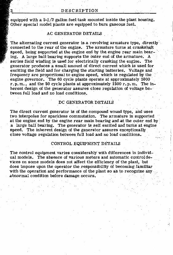

OPERATION
PRELIMINARY Be sure that the plant has been properly installed and prepared for operation before starting it Turn
onthe fuel supply and check for leaks correcting any that may be found See that the circuit breaker handle is in the OFF position so that no load is connected
CAUTION
If the preparation has been made for extremely cold weather using diluted No lOW oil the initial fill shying of the crankcase with diluted oil should have been left to be done immediately before starting the plant Be sure the crankcaSe is filled with the proper oil to the high level mark on the bayonet gauge bull
CHECK~HE OIL PRESSURE IMMEDIATELY AFTER STARTING esshypecially after the initial start (starting the plant for the firsttime after it has been installed or taken out of storage) Long storage periods may cause the oil pump to lose its prime making it necessary to poul oil into the pressure line preferably at the pressure relief valVe mecshyhanism
Oil was sprayed into the cylinders before the plant was shippedand it may be necessary to remove and clean the spark plugs ingasolinebeshyfore the engine will start the first time Dry the plugs before reinshystalling them
STARTING THE PLANT ELECTRICALLY - See thatthe ignition switch is set at themiddot
ELEC START position Ifmiddot the plant is to be operated on gasoline fuel press the START button firmly for several seconds to allow the fuel pump to become full and to pump gasoline into the carburetor The carburetor is automatically choked and the engine should start after a few seconds of cranking Hold the start button inuntil the plant has re achedrunrring speed If itdoes riotstartdonot presslheSTARTbtit shyton continuouSly but for periodS of not more than fiVEr seconds ata time with equivalent stops between If the plant fails to start after a few attempts check thefuel and ignition systems and repeal the proshycedure after correcting the trouble
If the plant is equipped for natural or Liquid Petroleum Gas operation see that the arm of the choke control mounted upon the exhaust manifold
is locked down so as to make the choke inoperative Nomiddotchoking is necshyessary when operating onmiddot gas and the carburetor choke valve should be wide open See tliat the gasoline supply is turned off and that there is no gasoline in the carburetor bowl Turn on the fuel supply and press the STARTbutton~ The regulatorprimet button at theltctmter Of the
regulator may have tobepJishedto start the engine the fUst time Do
16 OPERATION
notoverprime Unless the fuel to be used is of approximately the same BTU rating as that used by the manufacturer (1000 BTU) it will be necshyessary to readjust the carburetor gas adjustment valve to insure smooth and economical operation See the section headed ADJUSTMENTS
A closer spark plug electrode gap appears in the Table of Clearances as recommended to facilitate starting when operating with gaseous fuel
- - ~
STARTING THE PLANT MANUALLY - If gasoline fuel is used use the hand crank to turn the enshy
gine over enough times to fill the fuel pump and carburetor Throw the ignition switch to the HAND START position Crank the engine with a quick upward pull If the plant is equipped with the Sisson automatic choke have someone pull up on the automatic choke arm while crankshying Some plants are specially equipped with a low oil pressure ignishytion cut-off switch These special plants have a momentary contact toggle type switch located at the front of the plant This switch byshypasses the low oil pressure cut-off when in contact Hold this toggle switch in contact while manually cranking the engine and hold in conshytact until the plant has reached running speed If the plant is equipped with a manually operaJedchoke operate the choke as required by temshyperature conditions Do not spin the crank or press down on it If gas fuel is being used it may be necessary to press the regulator priming button at the center of the regulator to start the engine the first time Do notoverprime For manually starting a plant equipped for gas fuel the gas should have a BTU rating above 800 BTU per cu ft The temshyperature should be above 30o F (_loC) See that the automatic choke arm is locked down After the carburetor gas adjustment valve has been properly adjusted it should be unnecessary to use the priming buttonbull After the plant starts be sure to return the ignition switchto the ELECT START position
CAUTION
KEEP THE IGNITION SWITCH AT THE ELECT START POSITION AT ALL TIMES EXCEPT WHEN ACTUALLY STARTING THE PLANT MANUALLY THROW THE SWITCH TO THE HAND START POSITION WHILE CRANKshyING THE PLANT MANUALLYBUT RETURN IT TO THE ELECT START POSITION AS SOON AS THE PLANT STARTS bull
WHILE THIS SWITCH IS AT THE HAND START POSITION THE HIGH WATER TEMPERATURE CUT-OFF SWITCH (AND LOW OIL PRESSURE SWITCH IF THE PLANT IS SO EQUIPPED) IS CUT OUT OF THE CmCUlT AND THE PLANT IS NOT PROTECTED AGAINST OVERHEATING IF THE SWITCH IS LEFT AT THE HAND START POSITION WHEN THE PLANT IS NOT RUNNING THE BATTERY MAY BECOME DISCHARGED AND THE IGNITION COIL DAMAGED bull
OPERATION
If the plant will start but does not continue to run when electrically cranked possibly the start button is being released too soon If not try starting the plant manually If the plant starts and continues to run with the ignition switch at the HAND START position but stops when thrown to the ELECT START pOSition trouble is indicated in one of the relays the high water temperature switch or a loose connection
CHECKING THE OPERATION - After the plant starts allow the enshygine to reach operating temperature
Check the level of the coolant in the radiator as the thermostat may have allowed an air pocket to form thus preventing complete filling Add coolant to bring the level to the proper point if necessary The oil pressure should be between 20 and 40 pounds the coolant temperashyture approximately 1500 to 1800 F (650 to 820 C) and the battery charge rate between 2 and 7 amperes depending upon the charge conshydition of the batteries
When the plant is not in operation the water temperature gauge will register 2120 F The fuel gauge oil pressure gauge ~nd charge ammeshyter will register zero If it is desired to check the water temperature or fuel supply when the plant is not running throw the ignition switch to the HAND START pOSition while making the observation Besure to return the switch to the ELECT START pOSition after making the obshyservation While the plant is running the various gauges are automashytically in operation when the ignition switch is at the ELECT START position
Connect a load to the plant by throwing the main line switch or conshytrol panel circuitbreaker if the plant is so equipped to the ONposishytion The no load voltage is approximately 123 volts for the 115 volt plant after the plant has reached operating temperature The full loadvoltage is approximately 110 volts for a 115 volt plant Voltage will be correspondingly higher for plants of other voltages If the plant tends to surge or the voltage tends to fluctuate it is usually an indicashytion the engine needs additional warm-up before connecting a heavymiddot load ThOse plants which are equipped with the electrical meter panel have a circuit breaker which will automatically disconnect the load if the plant is severely overloaded~ If the plant is not equipped with the circuit breaker keep the correct size fuse in the load line switcbmiddot Those plants equippecentl with an output receptacle on the panel will not register on the meters any load which may be connected to thereceptshyacle This receptacle is provided for a trouble light or similar light load up to 15 amps 115 volts for each outlet
Continuous overloading of the generator will cause the generator temshyperature to rise to a dangerous point and lead to early failure of the windings If the main line fuse should blowout ortheplaIit circuit brlaker open remove the cause of overloading before again connectshy
18 OPERATION
ing the load to the plant On the three phase plant if part of the load is single phas~ the total load on any one leg should not exceed one third the total capacity of the generator On the 115230 volt plant divide the load as closely as possible between the two circuits when using 115 volt current Confine the load on each 115 volt circuit to not more than 2500 watts
HIGH WATER TEMPERATURE SWITCH - The high water temperature) switch is standard equipshy
men on the housed type of plant This switch is optional equipment on other models If the engine water temperature rises to a dangerous pOintthe cut-off switch operates to automatically close the stop circuit having the same effect as pressing the stop button on the plant The enshygine must cool off approximately lOaF before it can be restarted aftermiddot the cut-off switch has operated Before attempting to start the plant after the cut-off switch has operated determine and correct the cause of the high temperature
LOW OIL PRESSURE SWITCH - Some plants are equipped with a low oil pressure cut-off switch On these
plants if the engine oil pressure falls to approximately 6 pounds the cut-off switch operates to closethe stop circuit stopping the plant Deshytermine and correct the cause of the low oil pressure before attempting to again start the plant
EMERGENCY OPERATION If a burned out relay switch or other temporary difficulty prevents normal
operation of the plant with the ignition switch at the ELECT START pOSition the plant may be run temporarily with the switch at the HAND START position This is purely an emergency measure and should be resorted to onlyif necessary The starting batteries will not receive any charging current and all relays etc are cut out of the engine control circuit Keep a careful check on the plant while operating under these conditions
STOPPING THE PLANT - To stop the plant press the STOP switch momentarily The stop Circuit will not
work if the ignition switch is at the HAND START position In an emershygency if the stop circuit fails towork stop the plant by turning off the fuel supply
For
ABNORIVIALOPERATING CONDITIONS
LOW TEMPERATURES
Lubricationfuel and the cooling system require special attention at temperatures below 320 F (OoC)
CRANKCASE OIL - If the plant must be started after standing unused in temperatures between 320 F (OoC) and OOF
(_lSoC) use a good quality oil of SAE number 20Win the crankcase temperatures below OOF (-lSoC) use SAE number 5W oilbull The oil should be the detergent or heavy duty type
If number 5W oil is not obtainable dilute number lOW oil with apptoxishy
mately I part of kerosene t04 parts of oil Thoroughly mix the oil and kerosene just before pouring into the engine Immediately start the plant and run for at least 10 minutes to thoroughly circulate the mixtute through the engine Do not put diluted oil into the engine until ready to start the plant Mix the oil well just before pouringit into the engine Always use a mixture of the same proportions when adding oil between changes When using diluted oil changethe oil every 25 operating hours and check the oil level frequently bull Use undiluted oil again asspon as temperature conditions permit
CAUTION
Always drain the oil only when the engine is warm Drain the oil filter when changing to a lighter oil Add sufficient oil to compensate for that used to fill the oil filter
AIR CLEANER If congealed oil or frost formation within the air cleaner restricts the air flow remove and clean the
air cleaner Reassemble and use the air cleaner without oil until conshyditions permit the use Of oil in the normal mannerbull
COOLING SYSTEM - Themiddot coolant must be protected if there is any posshysibility of its freezing Use any good antifreeze
in the proportion recommended by the manufacturer for the lowest temshyperature to which the plant will be exposed The capacity of the cooling system is approximately 11 quartsbull
If the plant is to be stored in freezing temperatureswithout adding anti shyfreeze solution be sure to open the cylinder block drain cock to thorough ly drain aU water middotfrom the block after draining the radiator
If the water temperature gauge shows the engine to be operating too cool a portion of the radiator surface may be covered to raise the coolant temperaturemiddot to normal Avoid over heating~ Set the high water temper aturecut-off switch to operate at a temperature several degrees below
20 ABNORMAL OPERATING CONDITIONS
the boiling point of the coolant taking into consideration the altitude atmiddot which the plant is operating and the type of anti-freeze solution used
Check the anti-freeze solution frequently
FUEL GASOLINE - Use freSh clean high test (not highly leaded premium) gasoline for easy starting in cold weashy
ther bull Keep the fuel tank nearly full in order to prevent moisture conshydeIisatiQn within the tank which can cause considerable trouble from ice formation in the fuel system Do not fill the fuel tank entirely fuli of gasoline for expansion as the plant warms up may cause it to overshyflow
FUEL GAS OR VAPOR- Some types of Liquid Petroleum Gas will not vaporize readily at low temperatures Heat
exchanger equipment is available at extra cost and should be installed at the factory if temperature conditions require it
BATTERIES - Check the charge condition of the batteries frequently to be sure that they are kept in a fully charged condishy
tion A discharged battery will freeze at approximately 200F (_70C ) and be permanently damaged A fully charged battery will not freeze at -900F (-670C) Run the plant for at least 20 minutes after adding water to assure mixing the water with the electrolyte
HIGHmiddotTEMPERATURES
COOLING SYSTEM - If the plant is tobs operated in abnormally high temperatures (above 1000F or 3SoC) provide
sufficient air circulation for proper cooling Keep the cooling system cleap and free of rust and scale See that the high water temperature cut-off switch is correctly set and that the ignition switch is at the ELECT START position Keep the ignition timed correctly Keep the radiator well filled the fan belt tension properly adjusted and the crankcase oil level at but not above the upper level mark on the oil level gauge
CAUTION
For best cooling effects keep the door panels in place on the plant when it is in operation
Use SAE number 30 oil for temperatures up to lOOoF (3SoC ) and SAE number 40 for higher temperatures Check the oil level frequently and change the crankcase oil at least every 50 hours Keep the electshyrolyte level in the batteries up to normal
BATTERY - For a usual plantinstallaUon follow the instructions for Batteries under INSTALLATION If the installation
ABNORMA L OP ERATING CONDITIONS 21
agrees with the following description prepare the battery to assure long life by REDUCING BATTERY SPECIFIC GRAVITY
Standard automotive type storage batteries will self discharge very quickly when installed where ambient temperature is always above 900 F such as in a boiler room To lengthen battery life adjust the electshy
trolyte from a normal of 1 275 reading at full charge to a 1 225 readshying
The cranking power of the battery is also reduced when electrolyte is diluted to reduce acid activity and thus lengthen battery life If tempershyature is conSistently above 900 F (32 20 C) adjust the electrolyte as instructed below
1 Fully charge the battery DO NOT BRING AN OPEN FLAME OR BURNING CIGARETTE NEAR THE BATTERIES ON CHARGE BEshyCA USE THE GAS RELEASED DURING CHARGING IS VERY INshyFLAMMABLE
2 While battery is on charge use a hydrometer or filler bulb to siphon off all of the electrolyte above the plates in each cell Dont attempt to pour of0 I Dispose of the removed electrolyte AVOID SKIN OR CLOTIDNG CONTACT WITH ELECTROLYTE
3 Fill each cell with pure distilled water 4 Recharge the batteries for one hour ata 4 to 6 ampere rate 5 Use a reliable hydrometer to test each cell If the specificgravshy
ity is above 1 225 repeat steps number 2 3 and 4 until the highshyest specific gravity reading of the fully charged battery is not over 1 225 Most batteries require repeating steps 2 3 and 4 two times
DUST AND DIRTmiddot
Keep the plant as clean as practicable Service the air cleaner asfre quently as conditions require Keep the radiator flns clean and free of obstructions Keep the generator commutator and slip rings and brushes clean See that aU brushes ride freely in their holders Kecep oil and gasoline supplies in air tight containers Install a new oil filter eleshyment as often as necessary to keep the oil clean Change the crankcase oil more frequently if it becomes discolored before thenormal time has elapsed between changes
22 PERIODICmiddot SERVICE
GENERAL- Follow a definite schedule of inspection and servicing to assure better performance and longer life of the plant at
minimum expense Service periods outlined below are for normal sershyvice and average operating conditions For extreme load conditions or abnormal operating conditions service more frequently Keep a record of the hours of operation each day to assure servicing at the proper pershyiods
DAlLY SERVICE
If the plant is operated more than 8 hoUrs daily perform the DAILY SERVICE operations every8 hours
FUEL If the plant is operated on gasoline fuel check the fuel gaug~ often enough to assure amiddot continuous fuel supplymiddot Do not fill
the tank while the piantisrunning~
RADIATOR - Check the level of the coolant arid jf necessary add sufficient liquid 10 ~ing the level up to within one or
two inches of the bottom of the filler neck In freezing weather if a nonpermanent type anti-freeze is used check the protective strength of the coolant
AIR CLEANER - Check the oil level in the air cleaner cup and add sufficient oil to bring it10 the indlcated levelbull Clean
out and refill theoil cup ifdusty conditions prevail
CRANKCASE OILLEVEL- Check the oil level as indicated on the bay-net type oil level gauge Do not allow the
engine to operate with the oil level close to the low level mark on the gauge Add sufficient oil of the proper SAE number 10 bring the level 10the llpper level mark but do not overfill the crankcase
CLEANING - Keep the plant as clean as possible A clean plant will give longer and more satisfactory service
WEEKLY SERVICE
If the plant is operated more than 50 hours a week perform the WEEKLY SERVlCE operashytions every 50 hours
CRANKCASE OIL - Add crankcase oil as necessary or change the oil after 50 operating hours If the plant has been
operating with diluted oil change the oil after 25 hours operation
PERIODIC SERVIC E 23
GENERAL LUBRICATION - middotThe ball joint on the governor linkage will function best and have extended life if it U
lubricated only with powdered graphite However if graphite is not avshyailable a light non-gummy lubricating oil should be applied
Fill the distributor oil cup Put several drops of oil in the oil holes at each end of the battery charging generator and in the oil hole at the forward end of the starting motor of the direct current battery ignitionplane
Am CLEANER - Clean the air cleaner fUterelement and cup thorougshy hly in gasoline or other suitable solvent Allow to
dry or use compressed air to dry Refill the cup to the indicated level with clean oil of the same SAEnumber as that used in the crankcase except as noted under ABNO~MALOPERATING CONDITIONS~
FAN BEmiddotLT- Check the fan belt tension Adlustto permit about 34 play when pressure is applied midway between tpe fan
and crankshaft pulleys See ADJUSTMENTS section~ Install an new belt jf the old one is badly worn
BATTERIES - See that battery connections are clean and tight Keep the electrolyte level at the proper level above the plates
by adding only clean water which has been approved for use in batteries In freezing weather run the plant at least 20 minutes after adding water to mix the water with the electrolyte
SPARKPLUGS- Gleanthesparkplugsand checkthe electrodes gap Keep the gap adjusted toO 025for gaspline operashy
tion or at O 018 gap for gaseous fuel operation More frequent spark plug service may be necessary if leaded gasoline is used
WATER PUMP LUBRICATION - The water pump on only those plants built prior to model Spec J require
future lubrication Use a good grade of water pump gr~asein the water pumpgrease cupbull Turn the grease cup capdown 1 turn lteaCh 50 hours of operation If grease appears in the coolant thewaterpumpisbeing overlubricated To correct turn the CaP downless than 1 turn
DISTRIBUTOR - Check the distributor contact points Jftlleyare()nly slightly burned or pitted remove and middotrestirfacethem
on a fine stone Install new contact points if the old ones are badly burned Keep the gap adjusted to O 020 Excessive burning or pittiIlg of the points indicates aiaulty condenser which should be replacedwtth a new one
24 PERIODIC SERVIC E
MONTHLY SERVICE
If the plant is operated more than 200 hours a month perform the MONTHLY SERVICE operations every 200 hours
FUEL SYSTEM ~ Remove the pipe plug at the bottom of the carburetor and drain the carburetor of any sedimerit which may
have accumulated
Remove the cover and filter screen from the fuel pump Clean the screen thoroughly Reassemble the screen and cover Be sure the coshyver gasket is in good condition Be sure there are rio leaks at any point in the fuel system
DISTRIBUTOR - Place one drop of light oil on the distributor breaker arm pivot pin several drops on the felt pad under the
rotor and three or four drops on the flyweight mechanism distributed where it will reach friction points Place a light coating of grease on each cam lobe where the breaker arm block rubs
EXHAUST SYSTEM - Inspect all exhaust connections carefully Make any necessary repairs
COOLING SYSTEM - IIi some localitiespresence of lime or mineral deposits in the water may necessitate frequent
flushing of the plant cooling system Remove the top and bottom radishyator hoses If available connect a source of water under pressure to the bottom of the radiator and reverse ilushuntil the water runs clear from the top radiator connection Repeat the operation on the engine reversing the usual flow by running the water in at the outlet elbow Make Sure hose connections are tight when refilling the cooling system OIL FILTER - It is normal for detergent type crankcaSe oil to beshy
come discolored in usebull Intervals of filter element renewal must be determined by hours of operation operating condi- tions and engine condition rather than by oil discoloration when using detergent type oils IIistallation of a new filter element should coinshycide with an oil change Clean out the oil filter and install anew element The new filter ~lement will absorb approximately one quart of oil when the plant is started up After a short running period stop the plant and check the crankcase oil level Add oil as necessary to bring the oil up to the proper level
ENGINE COMPRESSION -Check the compression of each cylinder using a compression gauge Compression
of a new engirie when hand cranked is approximately 70 pounds A difshyference of more than 10 pounds pressure between cylinders indicates a compreSSion loss which should be corrected High compreSSion is an indication of excessive carbon or lead deposits in the combustion cham bers
25
PERIODIC SERVICE
CARBON REMOVAL - The frequency of necessary carbon and lead reshymovalservicing will vary with the typemiddotoffuel
used When a highly leaded gasoline is used it may be necessary to remove lead deposits more frequently than every 200 operating hours Remove the cylinder head and clean all carbon and lead deposits from the tops of pistons valves and top surface of the cylinder block Clean the deposits from the cylinder head If necessary grind the valves to a good seat
GENERATOR - Check the condition of the commutator collectorrings~ and brushes In service the commutator and collecshy
tor rings acquire aglossy brown color which is anormal condition Do not attempt to maintain a bright metallic newly machined finish If the commutator or collector rings become heavily coated clean with a lint free cloth Slight roughness may be remedied by lightly sanding with 00 sandpaper Clean out all carbon and sandpaper dust
When brushes are worn so that the top oithe brush is below a point midshyway between the top and bottom of the brush holder replace the brushes with newones~Brushes must ride freely in their holders and spring tenSion should be uniform Commutator brush spring tenSion is approxishymately 30 oz and collector ring brush spring tension is apprOximately 16 oz Tension should be measured with the free end of the spring level with the top edge of the brush holder
Gheck the brush rig for proper alignment of the reference marks on the brush rig and its s1lpport See Maintenance and Repair BrllSh Rig
GENERAL - Thoroughly inspect the plant for oil or water leaks loose electrical connections and loose bolts or nuts Make
any necessary repairs
SEMIYEARLY SERVICE Perform the foUoViingserv1ces periodically as specified i ~
GENE~ATOR BEARING -Remove the platefrOQl thehousingrear end I Thoroughly clean all dirt fromaround the
gener~tor bearing cover and remove the cover and gastet
LUbXi4late the generator b-all bearing at intervalS determined by the typ~of grease used Follow the paragraph of instructions below which agrees with the type of grease used Avoid mixing greases whenever practi~able
1 LilhiUmbaSe type bearing grease is used by and recommended by the factory This bearing grease is superior because it does not
run ard will not become hard or caked when used at temperatures
i
I
26 PERIODIC SERVIC E
ranging from minus 90oF to 12SoF bull With lithium base greaseservice the generator ball bearing each _5 000 operating hours or each 2 years Only a small q~tity of this grease need be used With a clean finger removeas mU(ili as possible of the old grease Force fresh grease iIito a 14 section of the bearing DO NOT fill the entire bearing Do not put a reserve of grease in the bearing recess nor in the bearing cover Q
IF dirt has gotten into the bearing remove the bearing and clean it in a good solvent Dry the bearing thoroughly and reinstall it
2 If ordinary good ball bearing grease is used service the generator ball bearing each 1200 operating hours or each 6 months With a
clean finger remove all the old lubricant and work approximately one tablespoonful of new bearing lubricant into the bearing Again clean out the bearing then refill about 12 full packing the lubricant well into the lower half of the bearing
Reinstall the bearing cover gasket and cover using care that no dirt gets into the bearing
ADJUSTMENTS
CARBURETOR GASOLINE - The carburetor should require no sershyvicing other thaIi keeping it clean and
free of sedimerit When cleaning jets and passages use compressed or a fine soft copper wire Be Sure that all gaskets are in their proshyper place whEln reassembling
Changes in the type of fuel used orin operating conditions may neces sitate a readjustment of the carburetor The main jet is not adjustable and its size has been selected to give the best performance The idle adjustment needle should be adjUsted to give the smoothest operation at no load Turn the idle adjustment needle out counterclockwise untn the engine begins to misfire then turn the needle in clockwise until the engine runs smoothly Adjust the throttle lever stop screw sothat there is 132 space between the screw end and the throttle stop when the plant is operating at no load
CARBURETOR GAS OR VAPOR - A change in the BTU rating of the fuel used will probably necessitate
readjusting the knurled head gas adjustment valve at the bottom of the carburetorbull With afuUloadon the plant turn the adjusting valve in (clockwise) until the voltage as shown on the AC voltmeter drops notice~ ably or the engine begins to lose speed Turn the screw slowly out (counterclockwise) until the voltage rises to normal and the engine runs smoothly If it is necessary to open the adjustment much beyond the point where normal voltage is attained in order to obtain smooth opera tion areadjustinent of the governor may be necessary Check the opshyeration at various loads There is no idle adjustment necessary for gas
or Butane-Propane vapor operation except to see that the throttle lever stop screw is adjusted to1 32 clearance between the screw end and the throttle stop with the plant operating at no load
ELECTRIC CHOKE - The choke was adjusted at the factory to operate ala temperature of 700 For 210 C In extremeshy
ly cold temperatures the choke may close so tightly that it willcause overchoking In extremely high temperatures a reverse situation may
occur To readjust this type of choke to function properly in very cold temperatures loosen the choke thermostat housing lockscrew and turn the thermostat housing slightly to the left (counterclockwise) To read~ just the choke for very high temperatures turn the thermostat housing tothexighf (clockwise) Be sure to tighten the lockllcrew after making the adjustment
SISSON CHOKE~ - Some plants are equipped with the Sisson choke conshytrol mounted on the exhaust manifold This type
choke control sll~uld not reqUire seasonal adjustments but may be read~ justed in the following manner Turn the shaft of the control to theposshyition where a 332 diameter rod or nail may be passed down through the hole in the end of the shaft opposite the lever Engage the rod or
middotCHOKE LOCK
ltJlUTOMATIC CHOKE CONTR OL LEv ER MUST as lOCKpoundD DOWN AS SHOWN WHpound PI T ISTO BE OPERATED ON
GAS
CH9Kpound PLATt
ROTATE poundNTIRE
UTOMAilC CHOKE
URETOR
-~R~~=l~~IAAEs~~_o~~~ P1ANTS
ELECTRIC CHOKE
USED ON GASOLINE OPER ATED PLANTS ONLY
FIG 5 CARBURETOR AND CHOKE ADJUSTMENT
Proshy
middot ADJUSTMENTS
nail in the notch in the mounting flange of the control Loosen the lever clamp screw just enough to allow the lever to be turned slightly To
adjust the choke for a leaner mixture push the lever downward To adjust the choke for a richer mixture pull the lever upward Retighten the lever clamp screw and remove the rod from the hole in the shaft Check to see that there is no binding or sticking action
GOVERNOR - The governor controls the speed of the engine and therefore the voltage and frequency of the current
per governor adjustment may be made as follows referring to Fig 6 Use a voltmeter while making the adjustments If a voltmeter is not av ailable the speed should be checked with a tachometer
1 With the engine stopped and tenSion on the governor spring adjust the governor linkage length so that the carburetor throttle stop lever clears the stop pin by not less than 164 as shown
2 Start the plant and allow it to reach operating temperature
SPEED CHART FOR CHECKING GOVERNOR REGULATION
SPEED SPREAb (WITHrn RANGE) LIMITS
iSPEED RANGE PREFERREDmiddot LINlITS (Approx)
MAX Mrn MAXF L to N L Mm FOR ALL 15 60 CYCLE PLANTS
CYCLE--64 57 59-61 35
451770-1830 100RPM-+1920 1710
3549-51 15 50 CYCLE PLANTS
FOR ALL CYCLE---54 47
451470-1530 100RPM --+-1620 1410
FOR DmEeuroT CURRENT PLANTS RPM----2000 1800 1800 100 NONE
i
30 ADJUSTMENTS
VOLTAGE CHART FOR CHECKING GOVERNOR REGULATION
TYPE OF PLANT VOLTAGE LIMITS PREFERRED VOLTAGE
ALTERNATING CURRENT PLANTS MAX MIN N L F L bull
N L F L PHASE WIRE
115 1 2 123 110 120 112 230 1 2 246 220 240 224 115230 1 3 123 110 120 112 120208 3 4 132 115 124 117 230 3 a 246 220 240 224 460 3 3 492 440 480 448
115 DIRECT CURRENT 120 115 115 115 230 DIRECT CURRENT 240 230 230 230
oiL
aAdjust the speed to give the desired voltage With no electrical load (N L) connected adjust the speed screw to the point where the voltage is nearest the desired voltage as shown in the VOLTAGE CHART for the type of plant in question Apply a full load (F L ) to the plant and again check the voltage Be sure the voltage is safe for the load applied An excessive voltage drop from full load to no load necessitates a sensitivity adjustment
Engine speed as checked with a tachometer should be nearest to the preferred limits as shown in the SPEED CHART
4 If the plant tends to hunt alternately increase and decrease speed) under load conditions increase very slightly the distance between the eye of the sensitivity screw and its support For best regulashytion ~eepthe screw in as close as possible without causing hunting ANY CHANGE IN THE SETTING OF THESENSITIVITY SCREW WILL REQUIRE CORRECTING THESPEEIJ SCREW ADJUSTMENT
5 If hunting occurs at NO LOAD screw the small bumper screw in un~il the hunt is stopped but not far enough to increase the engine sPred CAUTION Be sure all load is removed when adjusting the bumper screw
Be sure that all lock nuts are tightened as adjustments are compleshyted The governor can not operate properly if there is any binding sticking or excessive looseness in the connecting linkage or carshyburetor throttle assembly A lean fuel minture or a cold engine ~aycausehunting If the voltage drop is excessive when a full load is applied and adjustments are correctly made it is possible that the engine is low on power and should be repaired as necessary
ADJUSTMENTS Car6unto
~rhjhngtffleSiop Lever ~~vfver
ThrOffle SfopPin bull
uow PROXTEL HTWEEN BETWEEN STOP PIN NO LEVER N
Bumper Sc yew---
WIRSHING GOVERNOR PIERCE GOVERNOR
FIG 6 - GOVERNOR ADJUSTMENT
HIGH WATER TEMPERATURE SWITCH -Thehigh water- tempel1ture switch operates to stop the
engine if the coolant temperature rises too high I This prevents overshyheating which could cause serious damage to thf engine parts The enshygine may be started again when the coolant temp~rature drops approxishymately lOoF The dial adjustment should be setto operate at a tempershyature several degrees below the boiling point of the coolant taking into consideration the altitude at which the plant is operating Lower the setting 30 F for each 1000 feet above sea level The dial was set at 20SoF at the factory Do not set the switch to tperate at too Iowa temshyperature or the engine may be stopped before i~ reaches normal operashyting temperature The switch wiP not operate ~ the i~ition switch is at the HAND START POSITION 1
FIG 7 - HIGH WATER TEMP CUTOFF SWITCH 1
32 ADJUSTMENTS
FAN BELT TENSION - The fan belt tension is regulated by the width of the fan pulley groove The front half of the
pulley turns on the hub By loosening the two lock bolts arid turning the front half of the pulley clockwise the pulley groove is narrowed and the belt tightened Turn the pulley counterclockwise to widen the pulley groove and lessen the belt tension Allow 34 play in the belt as shown in the illustration Fig 8 Too tight a belt will have a short life and cause excessive strain and wear on the water pump bearings A belt too loose will slip wear out rapidly and will result in inefficient coolshying Be sure that the adjustment lock screws are properly tightened Check these screws frequently even when no adjustment is necessary
FAN BELT TENSION
FIGi- 8 - FAN BELT TENSION
II Ii
III
II ill
II I
III iii
III I
I1
Ii
III i
III II
III
I III ii
I
MAINTENANCE AND REPAIR 33 I j
i GENERAL - Refermiddot to the SERVICE DIAGNOSIS section for assistance in locating and correcting troubles which may occur The
information in this section is intended to assist in properly maintainingI the eqUipment and in making repairs Should a major overhaul become necessary it is recommended that the plant be carefully checked and
all necessary repairs made by a competent mechanic who is thoroughly familiar with modern internal combustion engines and revolving arma-
I ture type generators Referto the TABLE OF CLEARANCES herein
ENGINE
TIMING GEARS - The crankshaft and camshaft timmg gears are keyshyed to their respective shafts The camshaft gear
is fastened with a large hexagon nut and locking washer Thegears may be removed with a gear puller Always install both gears new I
I when either needs replaCing never one only The crankshaft gear has
one tooth punch-marked which must mesh with the two teeth punchshymarked on the camshaft gear See the illustration TIMINGGEARS~
I I
TAPPET ADJUSTMENT - The tappet adjustments may be reached by removing the valve chamber cover The
I tappets are the adjustable screw type requiring three wrenches to adshy
justSee the illustration TAPPET ADJUSTMENT
Adjust the valves for each cylinder as follows Crank the engine by I hand until the intake valve opens and closes Both valves for that cyshyI linder will then be closed Intake valves are numbers 2 3 6 and 7 The
adjusting screw clearance should be set to 0012 for both the intake and exhaust valves On engines which have the Roto type exhaust
I valves set the exhaust valve tappet clearance to 0010 Make sure the lock nut on each adjusting screw is securely tightened after the adshyjustment is made Tappets set too close may cause burned or warped valves seats and scored tappets or camshaft lobes Make a final check with the engine running at idle speed
VALVE SERVICE -The proper seating of the valves is essential to good engine performance If anyone valve is
leakingservice all valves Each valve its guide piston top the cyshylinder head and the top surface of the cylinder block should be thoroughshyly cleaned of all carbon depOSits Replace with a new one any valve of which the stem is worn or the head is warped or badly burnedbull The in~ take valve face angle is 300 and the exhaust valve face angle is 450 bull
All old valves to be reused should be groundand assembled t~ tlleirorshyigiriaLseats Grind only enough to assure a perfect seal Besureto remove all traces of grindipg compound from valves and seats Lightly
oUthe valves and guides b~ore reassembly
34 MAINTENANCE AND REPAIR
On some engines the exhaust valves are of the Roto type each valve having a cap under the end of the valve stem which pushes up against the valve spring retaining washer permitting the valve to rotate slighshy
tly as it opens and closes When reassembling install the cap on the end of the valve stem before installing the spring retainer locks Note that the exhaust valve retainer locks have a slight taper The thinner edge of the lock must face upward Be sure two locks are installed on each valve stem The intake valve locks are the single pin type If the Roto exhaust valves are properly installed it will be possible to turn them in their guides when fully open which is not possible with the conventional type valves set the tappet clearancesmiddot after the valves have been reassembled in the engine When tightening the cylinder head nuts start at the center of the head and work outward and towards the ends After approximately 10 hours of operation again check the tappet clearshyances making any necessary adjustments bull
IGNlTION TlMING - See Fig 11 Set the distributor contact points to 0020n gap at full separation There are stamped
markings on the flywheel which can be seen by removing the small flyshywheel inspection hole cover on the right side of the engine Crank the enshygine over with the hand crank until the No 1 piston is coming up onthe compression stroke Slowly crank the englne until the flywheel mark IGN centers in the inspection hole At this pOintthe distributor rotor should point to the distributor cap tower for the No 1 spark plug wire and the distributor pOints should just separate If the rotor points to the tower for the No 4 spark plug wire it will be necessary to remove the distributor lift the drive shaft in the cylinder head and turn it one half turn Start the plant and allow it to reach operating temperature Test the spark advance by applying a full electrical load Slow the enshygine by pulling on the governor arm then release and allow the engine to suddenly accelerate There should be one or two pings or detonashytion knocks If no ping is heard advance the timing If a continuous ping is present retard the timing Advance or retard the spark timing as necessary by loosening the distributor clamp and turning the distrishybutor body slightly clockwiseltto advancemiddot or counterclockwiseto retard Retighten the clamp screw Keep the spark advanced as far as possible without causing a ping or detonation under normal running conditions
PISTON RING REPLACEMENT - The piston and connecting rod assemshyblies are removed from the tops of
the cylinders Check the cylinders for out of round tapered or scored condition Rebore for oversize pistons if necessary Any ridge worn at the top of the cylinder should be removed if not reboring
Two compression rings and one oil control ring are used on each piston Fit each ring to its individual cylinder checking the gap between the ring ends by placing the ring squarely in the cylinder in a position corshyresponding to the bottom of its travel See Fig 12 The correct gap is
35MAINTENANCE AND REPAIR
FIG 9 - TIMING GEARS
AI82
rJ) -=-~_~ __ 1 middoth~
ADJUST VALVE CLEARANCE WHILE 7 shy
PISTON IS AT fiRING POSITION ~gtW
FIG 10 - TAPPET ADJUSTMENT
36 MAINTENANCE AND REPAIR
from 007 to 017 for compressiop rings 008 to 016 for oil rings Do not use rings which require too much filing to obtain the correct gap If using the old pistons clean all ring grooves of carbon despoits and see that oil return holes are open See that each ring fits its groove proshyperly with 0001 to 00025clearance Rings of the tapered type will be markEd TOP or may be otherwise easily identified and this taper must be installed with the smaller diameter toward the closed end of the piston Fit the proper ring in each ring groove on the piston spacshying the gaps equally around the circumference of the piston and no gap directly in line with the piston pin
PISTON REPLACEMENT - If cylinders become badly worn tapered or scored rebore and hone to fit one of
the available oversizes in pistons Pistons are available in 010 020 030 040 bull 050 and 060 oversizes The pistons should be fitted to the cylinders to a clearance of 0015 measured with a 12 wide feeler gauge inserted between the piston and cylinder at a point half way between piston pinholes A pull of 5 to 10 pounds should be required to pull the feller gauge past the piston See Fig~13 Piston and connecting rod assemblies must be properly aligned before install shyation in the engine
CONNECTING RODS - The connecting rod lower end bearings are steel backed and readily replaceable When removshy
ing the connecting rods be sure to note the numbers on the rods and bearing caps and reassemble with the numbers toward the camshaft Connecting rods 1 and 3 are not interchangeable with rods 2 and 4 Ilor are the bearings Notches machined in the connecting rod halves act as retainers for matching ears stamped into the steel back of the bearshying shells or inserts This design locks the shells and prevents their turning in the rod~ If a shell becomes worn both shells for that rod should be discarded and new ones installed The shells are designed to give a clearance of bull 0002 to bull 0022 without any scraping or other fitting Under no condition should fitting ever be attempted by scrapshying or filing of thecaporupperhalf of the rod asihis would permanshyently ruin the rod Be sure that rods and caps as well as bearing shells are perfectly clean and free of oilwhen inserting the shells Oil on the back of the shell will prevent proper seating of the shell in the rod or cap Oil the crankshaft journal after the bearing shell has been firmly seated
The sides of the connectirig rod crank ends are not babbitt lined in this
enginebull The faces are steel and being exposed to the steel crankshaft it is of vital importance that the side play clearance of 0065 to 00105 be maintained When installing new pistons pins or connecting rods ~
be sure pistons and connecting rod assemblies are first properly alignshyed on an accurate aligning gauge
31
IGNITION MARKS ON FLYWHEEL
I -RAOIATOT ENO Of ENGINE--o-shy
FIG 11 - IGNITION TIMING
FIG 12 - PISTON RING GAP
~-middotGUGE
FIG 13 -PISTONFlTTlNG
38 MAINTENANCE AND REPAIR
MAIN BEARINGS The crankshaft main bearings are of the same type as the connecting rod bearings The upper and lowshy
er shells are made in pairs for each individual bearing but front censhyter and rear be~rings are not interchangeable as pairs The same genshyeral directions given for fitting the connecting rod bearings should be observed in fitting the main bearings The clearance when installed should be 002 to 0024 The rear face of the front mainmiddot bearing takes the end thrust of the crankshaft The crankshaft end play should be 004 to 006 and is regulated by a removable thrust collar just to the rear of the crankshaft gear together with a shim pack to the rear of this collar When servicing the crankshaft or any parts in connection with the shaft especially connectitlg rod and main bearings always be sure that all oil holes in the shaft are open and clean Note that one censhyter main bearing cap screw is shorter than the other bearing cap screws This shorter screw musLbe installed on the camshaft -side of the bearshying cap Use of one of the longer screws at this point will block the oil passager BEARING CAUTION Certain engines are equipped with MORAINE I
i DUREX-IOO main bearings and (or) connecting rod bearings After a few hours of operation the bearing becomes a leaden gray in color and develops minute carters almost cellular in appearance TIllS APPEARANCE IS A NATURAL CHARACTERISTIC OFTHlS TYPE BEARING AND IN NO WAY INDICATES FAILURE Reasons for necessary bearing replacement are Wear on bearings causing a noticeable drop in oil pressure Damaged bearings due to deep scratches or gouges Loss of babbitt overlaydue to lubrication failure overheating or other abnormal conditions Before replacing bearings clean them thoroughly but NEVER USE ABRASIVES which may become imbedded Improved performance is gained by this bearing
PlSTONPINS The hardened piston pins are selected in production to obtain a 00004 loose fit in connecting rod pin bushshy
ing and 1ight push fit in piston boss By heating the piston in hot water the pisteR pin can be pushed in by hand MaintaiD these clearances if necessary to fit oversizemiddot piston pins Pins are available in bull 003 bull 005 and010 oversizes When reinstalling old pistons be sure that they are installed in their original cylinder and in the same pOSition relashytive to the numbered side ofthe connecting rod When reassenibling make sure that the snap ring at either end of the pin is tightly in place
CAMSHAFT The camshaft is an alloy steel forging Provided that proper lubrication is supplied the camshaft and its
bearings should never require servicing The cams if cut by too close adjustment of the tappet clearance can be reconditioned by careful honshy
ing if not too badly damaged The camshaft bearings are bronze bushshyings which are line reamed after installation in th~ crankcase to a clearance of 002 to 004 for front and rear or bull 003 to 0045 for
39MAINTENANCE AND REPAIR
center bushings The installation of new camshaft bearings is not practicable without the proper line reaming equipmenL
WATER PUMP The water pump on engines PRIOR TO SPEC J are a centrifugal ball bearingself sealing type To
dismantle the pump proceed as follows~
1 Remove the nut and lockwasher from the front of the water pump shaft end using a suitable puller pull tre pulley oft the shaft
2 Remove the three nuts mounting the shaft support to the body and remove the support assembly
3 To remove the impeller remove the set screw and pull or press the impeller from the shaft Note that if the set screw is loosened only a few turns it will not be free from jj the hole in the shaft
4 To retpove the shaft and bearings from the support remove the set screw from the top of the support and press the assem bly out through the front
5The seal will be found assembled in the impeller h~~ Care must be taken in removing this assembly as the carbOn seal IS fragile and easily broken~ To reassemble reverse the procedure used in disassembly When reassembling the pump make sure that the set screw projects far enough to line up the impeller on the shaft Press the impeller on flush with the end of the shaft Pack the space between bearings with a good grade of waterpump grease bull
WATER PUMP (For Models Beginning with SPEC~J) -The water puinp on
this eurongine is a centrifugal self sealing prelubricated ballbearing type To dismantle the pump follow this procedure
1 Remove the water pump assembly from the engine
2 Remove the screwsthat hold the end plate on the back of the water Ptlmp assembiy
3 Use a suitable puller to remove the pulley from the impellershaft
4 Remove the lock ring that retains
the bearin~apound)he p~lley end~
5 Press the impeller shaft out of thebody castingf~om1hemiddot~~-of the water pump This frees the impellerbullbull t
40 MA~NTENANCE AND REPAIR
6 Tap the shaft seal out by inserting a plug through the front of the casting Tap out the seal gently to prevent any damage to the seal
7 Reverse the disassembly steps in order to assemble the pump Note that the impeller hub is assembled to the impeller shaft with the fins facing the water pump seal
CRANKCASE VENTILATION - The crankcase oil fill cap permits entry of air to the crankcase which is
drawn out through the valve chamber cover tube to the intake manifold If the oil fill cap becomes clogged with dust and dirt excessive crankshycase vacuum may build up causing oil to be drawn from the valve chamshyber into the intake manifold The baffle plate on the inner side of the valve cover must be in place and undamaged for proper ventilation
LUBRICA TION SYSTEM - A gear type oil pump supplies oil under ~ pressure through drilled passageways to the crankshaft main bearings lower connecting rod bearings cam- shaft bearings and valve tappets Wheneverthe engine is disassembled
I for servicing make sure that all oil passages are unobstructed i Thoroughly clean the engine oil pan and the oil pump strainer screen
An oil pressure relief adjustment is adjusted at the factory to give a pressure of 20-40 pounds at the governed speed with the engine oil hot The oil pressure relief adjustment is reached by removing a large he~agon shaped plug in the side of the crankcase just below the oil filter and adjusted by addirig or removing spacerwashers
I
FIG 14 - BOTTOM VIEW OF ENGINE
41MA INTENANCE AND REPAIRmiddot
TABLE OF CLEARANCES
NOTE
The clearances given below are for settings at 720 F (22 20 C)
MINIMUM MAXIMUM Valve Tappets - Roto Exhaust ~ 010 Valve Tappets - Intake and Exhaust (Conventional) 012 Valve Seat Width ~ Intake and Exhaust 116 332 Crankshaft Main Bearings bull 0002 0024 Crankshaft End Play 004 middot 006 ConnectingRoa Bearingmiddot 0002 bull 0022 ConnectingRod Side Play-(Desired 0065) 0065 middot 0105 Piston in Cylinder middot 0015 Camshaft Bearings - Front and Rear 002 bull 004 Camshaft Bearings - Center bull 003 bull 0045 Distributor Breaker Points Gap bull 020 Spark Plug Electrode Gap-For Gasoline Fuel bull 025
Spark Plug Electrode Gap-For Gaseous Fuel 018 Piston Compression Ring Gap 007 bull 017 Piston Oil Ring Gap 008 bull 016 Crankshaft Main Brg Journal- Std Size 1 7475 1 7485 Crankshaft Rod Brg Journal - Std Size 1 499 1 500
42 MAINTENANCE AND REPAIR
i
i
GENERATOR
GENERAL - The generator normally requires little maintenance other than the PERIODIC SERVICE
COMMUTATOR AND COLLECTOR RINGS -After a long period of servict the surface of
the commutator may become worn to such an extent as to cause the mica insulation between the commutator bars to extend above the level of the bars This condition would cause noisy brushes andmiddot would soon lead to excessive brushsparkingand pittingof the commshyutator bars High mica should be undercut toadepth equal to the distance between barsorapproximately 132 Lift each brush high in its guide so that its spring will press against its Side and remove the end bell Tag leads to insure correct replacementmiddot With a tool fashionedfrom a hack saw blade carefully undercut the mica Be
sure to remove any burrs which may have been formed when undershycutting and see that spaces between bars are completely free of any metallic particles
Should dusty operating conditions cansethe surface of the commutator orcoUector rings to become grooved out of round pitted or rough it will be necessary to remove the armature and turn the commutator or collector rings down in a lathe It will be necessary to remove the generator field frame before the armature can be removed Remove the ball bearing from the armature shaft before turning down to preshyvent any foreign material getting into it After the commutator is turneddownthe mica between bars must be undercut as described above When the armature is reinstalled align it as carefully as possible before installing the frame and end bellbull
BRUSH RIG - Itisnnnecessary to remove the brush rig from the end bellwheilserviclng the generator If it has been
removed mistakenly lineup the paint mark on the outer edge of the brush rig withthe mark on thebrnshrig support in theeIid belLmiddot Amiddot deviation from the proper positioning of the brush rig will lead to excessive arcing ofmiddot the brushes burning of the commutator low generator output and possible irreparable damage to the generator windings due to overheating Any defective condenser should be reshyplaced with a new one of the same capacity
BRUSHES - Install new brushes when the olqonesare worn so that the top of the brush is belaw a point midway between the
top and bottom of the brush guide Donot continue to use brushes that are worn too short because the spring tension lessens as the brush
becomes shorter and weak spring tension leads to exceSSive brush sparking and pitting of the commutator or collector rings It is recshy
ommended that only a moderate load be applied to the generator until
PLVWHEEL (1
fLVWHUL
O AllIlATUIII DAM HUB DISC
~ AM DRlY[ DIampC-NUB
ARMAu 3 b
PAIR
t FIG 15 -ALTERNATING CURRENT GENERATOR ASSyi
BRUSH RIG ALIGNMENT
FIG 16 - CARE OF COMMUTATOR AND BRUSHES
44 MAINTENANCE AND REPAIR
the new brushes have been run in~toeliminateexcessivesparking See that brushes ride freely in their guides and that spring tension
is uniform The correct tension is 30 oz for the commutator brush springs and 16 oz for the collector ring brush springs measured with the contact pojnt of the spring level with the top oUhe guide
GENERATOR wlNDINGS - Use a continuity type testlamp set to test for grounded or opencircuits in thegenshy
er~tor windings Be sure that all brushes are lifted away from conshytact with the commutator and collector rings and that generator leads to the control panel are disconnected When disconnecting leads tag them to facilitate correct replacement Discotmect condenser leads from brush terminals to avoid mistaking a defective condenser for a grounded lead
I
t Use an armature growler to test the armature for an internal short circuit Field coil windings maYbetested far aninteInal short cir shy
cuit by comparative ohmeter readings
If one or more field coils test defective install a new set of field coils 1f an armature winding tests defective install a new Armature assembly Leads may be repaired as necessary
CONTROLS
CONTROL PANEL EQUIPMENT ~ If any of the control panel eqUipment fails to function properly the defshy
ective part should be replacedwith a corresponding new unit rather than to attempt repairs on the old part Disconnectthe battery whenever servicing any control panel eqUipment Keep all connections tight and clean
If the plant will start but does not continue to runstart the plant manshyually If it continues to run with the ignition switchaUhe HAND START positiontrouQle is indicated in one of the relays the high water temperature switch oraloose coimection An opencirCuitbe~ tween the generator and the stop relay will also prevent the plant from running with the ignition switch atihe ELECSTART position
DO NOT LEAVE THE IGNITION SWITCH AT THE HAND START POSshyITIONLONGER THAN NECESSARYTO MAKE TESTS
The plant is equipped with a start disconnect relaywhich serves to open the start circuit when the plant is started with automatic or line
transfer eqUipment Failure of the start disconnect relay to operate I I will cause the start circuitto remain closed after the plant startsiI and will allow an excessively bignv61tageto reach the batteries
I
45MAINTENANCE AND REPAIR
Failure of the reverse current relay (charge relay) may cause the charge ammeter to show a discharge of approximately 7 amps when the
~ plant is stopped Replace the relay with a new one if cleaning the corishytact points with a hard finish paper does not remedy the situation The correct adjustment is obtained by setting the spring tension to allow the relay points to open at 126 volts and close at 154 volts when testshyed on a test bench
The voltage regulator relay should allow a charge rate of approximately 6 amps when the batteries are less than 34 fully charged~ As the batteries approach a fully charged condition the charge rate should drop to approximately 2 amps or less The spring tension may be increased to advance the high charge rate cut in point or decreased to retard the point at which the high charge rate becomes effective
~ TROUBLE SHOOTING
A good rule to follow in locating engine trouble is to never make more than one adjustment at a time stop and think how the motor operates and figure out the probable cause of any irregular operation Then locate the trouble by a process of eliminatiop In many instances a symptom indicating trouble in one unit may be caused by improper function of a closely related unit or system Remember that the cause
usually is a SIlVIPLE ONE rather than a mysterious and complicated one
If a general tune-up is found necessary perform necessary operashytions in this sequence Spark Plugs Battery and Ignition Cables Distributor Ignition Timing Valve Clearance and Carburetor
46 SERVIC E DIA GNOSIS
POSSIDLE CAUSE REMEDY GENERATOR OVERHEATING
Overloaded Reduce load Brush rig out of position Be sure to line up marks See
Brush Rig
VOLTAGE DROPS UNDER HEAVY LOAD
Engine lacks power
Poor compression
Faulty carburetion
Restricted air cleaner
Excessive choking
Carbon in cylinderbull
Restricted exhaust line
See remedies for engine missing under heavy load
Tighten cylinder head and spark plugs Jfstill not corrected grind the valves Replace pisshyton rings if necessary Refer to MAINTENANCE AND REPAm
Check the fuel system Clean adjust or replace parts necessshyary
Clean and refill
See that choke opens properly
Remove carbonbull
Clean or increase the size
ENGINE MISFffiES AT LIGHT LOAD
Carburetor idle adjustment set wrong or clogged
Spark plug gaps too narrowbull
Intake air leak
Faulty ignition
Uneven compression
(contmued)
Adjustcleanif needed
Adjust to correclgap Refer toTABLE OF CLEARANCES
Tighten or replace gaskets
Cleanadjust or replace breakshyer pOints plugs condenser cOil etc or retime ignition
Tighten cy linder head and spark plugs If still not corrected grind valves Replace piston
rings if necessary
SERVICE DIA GNOSIS 47
POSSIBLE CAUSE REMEDY
Worn intake valve stems or guides
Spark plugs defective
Faulty ignition
Clogged carburetor
Clogged fuel screen
Defective spark plug cables
Replace valves or guides
Replace
Clean adjust or replace breakshyer points plugs condenser Goil etc or retime ignition
Clean jets
Clean
Replace
ENGINE MISFIRES AT ALL LOADS
Fouled spark plug
Defective or wrong spark plug
Sticking valves
Broken valve spring
Defective ignition wires~
Defective or improperly adjusted pOints
CI~an and adjust
Replace
Clean stems arid guides
Replace Replace
Adjust or replace breaker points See Periodic Service - Weekly
LOW OIL PRESSURE
Too long screw on center main bearing
Oil too light
Oil badly diluted
Oil too low
Oil relief valve not seating
Badly worn bearings
See MAIN BEARINGS
Drain refill with proper oil See PREPARATION
Drain refill with proper oil
Add oil
Remove and clean or replace See LUBRICATION SYSTEM
Replace See MAINTENANCE AND REPAIR
48 S E RYI C E DrAG N OSIS
possmLE CAUSE REMEDY LOW OIL PRESSURE
( continued) Sludge on oil pump screenbull Remove and clean
BadlyworIi oil pump~ Replace
Defective oilpresslire gauge Replace
HIGH OIL PRESSURE
Oil too heavy Drain refill with proper oil See PREPARATION
Clogged oil passage Clean all lines and passages
Oil relief valve stuck Remove andclean See LUB- RIGA TION SYSElVr
Defective oil pressure gauge Replacebull
PLANT STARTS BUT DOES NOT CONTINUE TO RUN
START button released toosoon~ Hold in contact longer
Defective panel equipment See Controls
ENGINE BACKFmES AT CARBURETOR
Lean fuel mixture
Clogged fuel screen
Intake air leak~ I
I Poor fuel
I Spark too latebull
Spark plug wires crossed
Intakeovalves middotleaking~
Clean carburetor
Clean screen
Replaceflangegasketstighteri carburetormiddot
Refill with good fresh fuel
Retime ignitionbull See IGNITshyION TlMING
lnstall wires correct Iy See IGNITION TlMING
Grind or replacebull See VALVE SERVICE
49SERVICE DIAGNOSIS
POSSIBLE CAUSE REMEDY EXCESSIVE OIL CONSUMPTION LIGHT BLUE SMOKY EXHAUST
Worn piston rings
Oil leaks from engine or connecshytions This does not cause smoky exhaust
Oiltoo light or diluted
Too large bearing clearances
Oil pressure too high
Breather cap clogged
Engine misfires
Faulty ignition
Unit operated at light or no load for long periods
Too much oil
Install new piston rings See PISTON RING REPLACEMENT
Replace gaskets or leaking tubshying Tighten screws and connshyections
Drain refill with correct oil See PREPARATION
Replace bearings See MAINshyTENANCE AND REPAm
Refer to symptoms of high oil pressure for remedies
Clean-See CRANKCASE VENshyTILATION
Refet to symptoms of engine misfires
Cleanadjusf or replace breakshyer points plugs condenser coil etc or retime ignition
No remedy needed
Drain excess oil
BLACK SMOKY EXHAUST EXCESSIVE FUEL CONSUMPTION FOULING OF SPARK PLUGS WITH BLACK SOOT POSSIBLE
LACK OF POWER UNDER HEA VYLOAD
Fuel mixture too rich~ Adjustchoke Install needed carburetor parts adjust float level
Choke not open See that choke opene properly See ADJUSTMENTS
Dirty air cleaner Clean refill to proper level
50 SERVICE DIAGNOSIS
POSSIBLE CAUSE REMEDY LIGHT POUNDING KNOCK
I I i
I
I i
i
Loose connecting rod bearing
Low oil supply
Low oil pressure
Oil badly diluted
Fuel tank empty
High water temperature
Defective ignition
ReiHace See MAINTENANCE ANDREPAm
Add oil
Refer to symptom of low oil pressure for remedies
Change oil
ENGINE STOPS UNEXPECTEDLY
Oil badly diluted
PINGING SOUND WHEN ENGINE IS RAPIDLY ACCELERATED OR HEAVILY LOADED
Carbon in cylinder
Spark too early
Refill
See symptoms for engine overshyheating
Check the ignition system Reshypair or replace parts necessary
DULL METALLIC THUD IF NOT BAD MAY DISAPPEAR AFTER FEW MINUTES OPERATION IF BADINCREASE
WITH LOAD
Loose crankshaft Replace bearings unless one of the next three remedies permanshyently corrects the trouble
SHARP METALLIC THUD ESPECIALLY WHEN COLD ENGINE FmST STARTED
Low oil supply Add oiL
Low oil pressure Refer to symptom of low preshyssure for remedies
Change oil
Remove carbon
Retime ignition See IGNITshyION TIMING
~
SERVICE DIAGNOSIS
POSSIBLE CA USE REMEDY
PlNGING SOUND WHEN ENGINE IS RAPIDLY ACCELERATED OR HEAVILY LOADED
( continued) Wrong spark plugs Install Champion J8 plugs or
equal in another brand Spark plugs burned or carboned Install new plugs
Valves hot Adjust tappet clearance See TAPPET ADJUSTMENT
Fuel stale or low octane Use good fresh fuel
Lean fuel mixture Clean carburetor
ENGINE CRANKS TOO STIFFLY
Too heavy oil in crankcase Drain refill with lighter oil
Engine stuck Disassemble and repair
ENGINE WILL N9T START WHEN CRANKED
Faulty ignition Clean adjust or replace breakshyer points plugs condenser coil etc or retime ignition
Lack of fuel or faulty carburetionRefill the tanle Check the fuel system Clean adjust or reshypwce parts necessary
Clogged fuel screen Clean
Cylinder flooded Crank few times with spark plugs removed
Poor fuel Drain refill with good uel
PoorcOmpression Tighten cylinder head and spark plugs~ If still not corrected
bull grind the valves Replace piston rings if-necessary See MAINshyTENANCE AND REPAIR
Wrong timing Retime ignition See IGNITION TIMING
52 SERVIC E DfA GNOSIS
POSSIBLE CAUSE REMEDY ENGINE RUNS BUT CURRENT DOES NOT BUILD UP
Poor brush contact or dirty commutator or Slip rings
Open circuit short circuit or gloundmiddotin generator
See that brushes seat well are free in holders are not worn too short and have good spring tension
See GENERATOR replace part necessary_
CURRENT UNSTEADY BUT ENGINE NOT l1lSFmING
Speed too low
Poor commutation or brush contact~
I i Loose connections
Fluctuating load
Adjust governor to correct speed
See that brushes seat well on commutator and Slip rings are free in holders are not worn too short and have good spring tenshysion
Tighten connections
Correct any abnormal load condition causing trouble
TAPPING SOUND
Tappet clearancetoo
great Adjust or replace tappets
Broken valve spring Instap new spring
HOLLOW C LICKING SOUND WITH COOL ENGINE UNDERLOAD
Loose pistons If noisy only slight and disappears when engine warms up no immshyediate attention neededOthershywise replace worn parts
VOLTAGE rOW AT FAR END OF LINE BUT NORMAL NEAR POWER UNIT
Too small line wire for load Install larger or extra wires or and distance reduce load
53SERVICE DIAGNOSIS
POSSIBLE CAUSE REMEDY
MOTORS RUN TOO SLOWLY AND OVERHEAT AT FAR END OF LINE BUT OK NEAR POWER UNIT
Too small line wire for load Install larger or extra wires or and distancebull reduce load
NOISY BRUSHES
High mica between bars of Undercut mica See GENERshycommutator ATOR
EXCESSIVE ARCING OF BRUSHES
Rough commutator or rings Turn down
Dirty commutator or rings Clean See GENERAIOR
High mica Undercut mica
Brush rig out of position Line up marks on brush rig and support
ENGINE OVERHEATING
Low water in radiator Refill radiator
Overloaded Remove part of load
Improper lubrication See Low Oil Pressure
Radiator obstructed Clean radiator
Ignition timing late Adjust See IGNITION TIMlNG~
i
54 STORING THE PLANT
PREPARING U~TITS FOR STORAGE OR EXTENDEDOUT-OF-SERVICE PERIODS - Electrical generating sets are often taken out of service
for extended periods of time In many cases they are left to stand idle without being protected against possible damage from rust and corrosion or the elements The factory recommendes that any unit to be removed from servipe for 30 days or more be protected by this method
Shut off the fuel supply at the tank and allow the unit to run until it stops from lack of fuel The fuel system will then be free of gasoline except for the tank
If the fuel tank will be subjected to temperature changes fill the tank nearly full to lessen chances Of condensation forming within the fueltank
JDrain the oil from the oil base while the engine is warm Replace the drain -plug See that the oil filler cap is in place Attach a warning tag th8toil has been drained
If the cooling system does not have antifreeze and rust inhibitor drain the entire cooling system Be sure to drain both the radiator and the bloCk
Remove each spark-plug and pour two tablespoonfuls of rust inhibitor oil (Use SAE 50 motor oil as a substitute) into each cylinder Crank the engine over slowly by hand to lubricate the cylinders stop the engine with the TC(top center) mark onthe flywheel mdicating at Jeast one piston is at top center position Replace the spark plugs
Clean the generator brushes brush holders commutator and collector rings by wiping with a clean cloth Do not coat with lubricant or other preservative
Remove clean and replace the air cleaner
Wipe all exposed parts clean and coat with a film of grease all suc~Partsmiddot lialgtle to rust~
Oil the governor to carburetor linkage with SAE50 oil
Plug the exhaust outletwitha wood plug to prevent entrance of moisture or foreign matter
Wherebatteries are likely to be exposed to freezing temperatures they must be removed and stored where there is no danger of freezing A fullycbarged battery can withstand very low temperatures but an idle battery gradually loses Rscharge and may become rlischarged to the -point where it Will freeze An idle battery should be given a fresh~g ~ charge about every 40 days
If the battery is not removed disconnect the cables from the unit Arshyrange the cables so that the lugs cannot come in contact with each other or with metalparts
STORING THE PLANT
Provide a suitable cover for the entire unit partiCularly if it will be exposed to the elements
RETURNING THE UNIT AFTER EXTENDED OUT-OF-SERVICE P laDS - Remove all protective coatings of grease from externalparts
Wipe the entire unit clean of accumulated dust or other forshyeign matter
Inspect the unit carefully for damage and for other conditions requirshying attention Service as needed Keep the side panels and top plate on the housing except while servicing They help direct the cooling air properly and reduce radio interference
_Remove the plug from the exhaust outlet
Remove clean and adjust spark plugs While the plugs are out crank middot the engine over several times by hand to distribute oil over the cylinder walls If the cylinders are dry put a tablespoonful of oil into each cylinder and turn the engme over several times by hand to distribute the oil Replace the spark plugs and gaskets
Examine all fuel oil and water lines and connections Service as needshyed
Refill the cooling system with clean fresh water
If antifreeze was left in the cooling system check the level and add a 50-50 solution of water and the type of antifreeze originally used to bring the cooling liquid up to proper leveLmiddot If deSired the antifreeze
middot solution can be drained and the cooling system refilled with clean middot fresh water
Refill the crankcase and air cleaner with the correct amount and grademiddot of oil
Check carefully for leaks of water fuel or oil after serviCing the unit Correct any leaks before starting the unit
CAUTIONmiddot
On the initbtl start (starting the plant for the first time after it has been installed or taken out of storage) check the oil pressure immediately Long storage periods may cause the oil pump to lose its prime
middot Connect the battery cables to the unit Carefully recheck to make sure the unit is ready for operation Then start the unit in the regular manshyner as described under OPERATION in the instruction manual Always connect the ground cable lastly
1
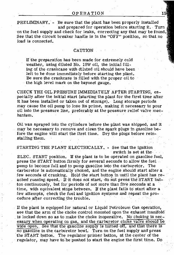
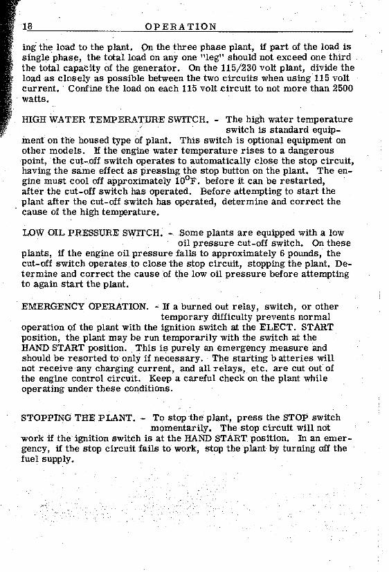
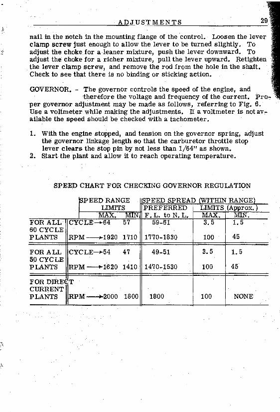
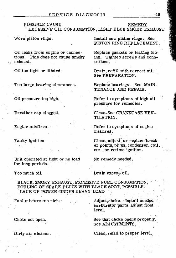
1