Embed Size (px)
Citation preview
Operator’sManual
MDKBH
Printed in U.S.A. 06-05 981-0176
California
Proposition 65 WarningDiesel engine exhaust and some of its constituents are knownto the State of California to cause cancer, birth defects, andother reproductive harm.
i
Table of Contents
SECTION PAGE
SAFETY PRECAUTIONS iii. . . . . . . . . . . . . . . . . . . . . . . . . . . . . . . . . . . . . . . . . . . . . . . . . . . . .
1. INTRODUCTION 1-1. . . . . . . . . . . . . . . . . . . . . . . . . . . . . . . . . . . . . . . . . . . . . . . . . . . . . . . . . .
About this Manual 1-1. . . . . . . . . . . . . . . . . . . . . . . . . . . . . . . . . . . . . . . . . . . . . . . . . . . . .
Model Identification 1-1. . . . . . . . . . . . . . . . . . . . . . . . . . . . . . . . . . . . . . . . . . . . . . . . . . . .
How to Obtain Service 1-2. . . . . . . . . . . . . . . . . . . . . . . . . . . . . . . . . . . . . . . . . . . . . . . . .
Emissions Label 1-2. . . . . . . . . . . . . . . . . . . . . . . . . . . . . . . . . . . . . . . . . . . . . . . . . . . . . .
2. CONTROL PANELS 2-1. . . . . . . . . . . . . . . . . . . . . . . . . . . . . . . . . . . . . . . . . . . . . . . . . . . . . . .
Local Control Panel 2-1. . . . . . . . . . . . . . . . . . . . . . . . . . . . . . . . . . . . . . . . . . . . . . . . . . .
Remote Control and Monitoring 2-1. . . . . . . . . . . . . . . . . . . . . . . . . . . . . . . . . . . . . . . . .
Digital Display 2-2. . . . . . . . . . . . . . . . . . . . . . . . . . . . . . . . . . . . . . . . . . . . . . . . . . . . . . . .
3. OPERATION 3-1. . . . . . . . . . . . . . . . . . . . . . . . . . . . . . . . . . . . . . . . . . . . . . . . . . . . . . . . . . . . . .
Fuel 3-1. . . . . . . . . . . . . . . . . . . . . . . . . . . . . . . . . . . . . . . . . . . . . . . . . . . . . . . . . . . . . . . . .
Engine Oil 3-1. . . . . . . . . . . . . . . . . . . . . . . . . . . . . . . . . . . . . . . . . . . . . . . . . . . . . . . . . . . .
Engine Coolant 3-2. . . . . . . . . . . . . . . . . . . . . . . . . . . . . . . . . . . . . . . . . . . . . . . . . . . . . . .
Batteries 3-2. . . . . . . . . . . . . . . . . . . . . . . . . . . . . . . . . . . . . . . . . . . . . . . . . . . . . . . . . . . . .
Fire Extinguisher Port 3-2. . . . . . . . . . . . . . . . . . . . . . . . . . . . . . . . . . . . . . . . . . . . . . . . . .
Pre-Start Checks 3-3. . . . . . . . . . . . . . . . . . . . . . . . . . . . . . . . . . . . . . . . . . . . . . . . . . . . . .
Priming the Fuel System 3-3. . . . . . . . . . . . . . . . . . . . . . . . . . . . . . . . . . . . . . . . . . . . . . .
Starting the Genset 3-3. . . . . . . . . . . . . . . . . . . . . . . . . . . . . . . . . . . . . . . . . . . . . . . . . . . .
Stopping the Genset 3-4. . . . . . . . . . . . . . . . . . . . . . . . . . . . . . . . . . . . . . . . . . . . . . . . . .
Emergency Stop 3-4. . . . . . . . . . . . . . . . . . . . . . . . . . . . . . . . . . . . . . . . . . . . . . . . . . . . . .
Loading the Genset 3-4. . . . . . . . . . . . . . . . . . . . . . . . . . . . . . . . . . . . . . . . . . . . . . . . . . .
No-Load Operation 3-5. . . . . . . . . . . . . . . . . . . . . . . . . . . . . . . . . . . . . . . . . . . . . . . . . . . .
Resetting Line Circuit Breakers 3-5. . . . . . . . . . . . . . . . . . . . . . . . . . . . . . . . . . . . . . . . .
Connecting to Shore Power 3-5. . . . . . . . . . . . . . . . . . . . . . . . . . . . . . . . . . . . . . . . . . . .
Cold Temperature Operation 3-5. . . . . . . . . . . . . . . . . . . . . . . . . . . . . . . . . . . . . . . . . . . .
Care of New or Re-Built Engine 3-5. . . . . . . . . . . . . . . . . . . . . . . . . . . . . . . . . . . . . . . . .
Exercising the Genset 3-5. . . . . . . . . . . . . . . . . . . . . . . . . . . . . . . . . . . . . . . . . . . . . . . . .
Storing the Genset 3-6. . . . . . . . . . . . . . . . . . . . . . . . . . . . . . . . . . . . . . . . . . . . . . . . . . . .
ii
SECTION PAGE
4. PERIODIC MAINTENANCE 4-1. . . . . . . . . . . . . . . . . . . . . . . . . . . . . . . . . . . . . . . . . . . . . . . .
General Inspection 4-2. . . . . . . . . . . . . . . . . . . . . . . . . . . . . . . . . . . . . . . . . . . . . . . . . . . .
Maintaining the Battery and Battery Connections 4-2. . . . . . . . . . . . . . . . . . . . . . . . . .
Checking Engine Oil Level 4-3. . . . . . . . . . . . . . . . . . . . . . . . . . . . . . . . . . . . . . . . . . . . .
Changing Engine Oil and Filter 4-4. . . . . . . . . . . . . . . . . . . . . . . . . . . . . . . . . . . . . . . . .
Draining/Replacing the Fuel Filter 4-5. . . . . . . . . . . . . . . . . . . . . . . . . . . . . . . . . . . . . . .
Maintaining the Engine Cooling System 4-6. . . . . . . . . . . . . . . . . . . . . . . . . . . . . . . . . .
5. TROUBLESHOOTING 5-1. . . . . . . . . . . . . . . . . . . . . . . . . . . . . . . . . . . . . . . . . . . . . . . . . . . . .
Troubleshooting with Digital Display 5-1. . . . . . . . . . . . . . . . . . . . . . . . . . . . . . . . . . . . .
Troubleshooting with Status Lamp 5-1. . . . . . . . . . . . . . . . . . . . . . . . . . . . . . . . . . . . . . .
6. SPECIFICATIONS 6-1. . . . . . . . . . . . . . . . . . . . . . . . . . . . . . . . . . . . . . . . . . . . . . . . . . . . . . . . .
7. MAINTENANCE RECORD 7-1. . . . . . . . . . . . . . . . . . . . . . . . . . . . . . . . . . . . . . . . . . . . . . . . .
iii
SAFETY PRECAUTIONS
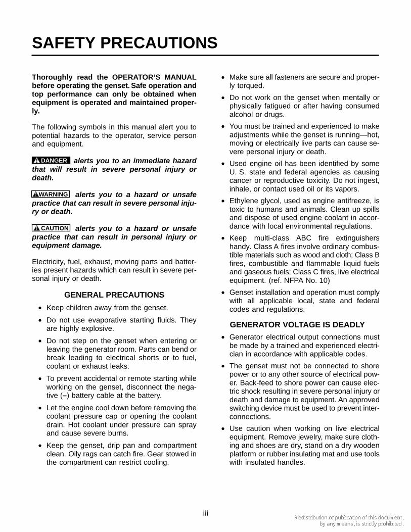
Thoroughly read the OPERATOR’S MANUALbefore operating the genset. Safe operation andtop performance can only be obtained whenequipment is operated and maintained proper-ly.
The following symbols in this manual alert you topotential hazards to the operator, service personand equipment.
DANGER alerts you to an immediate hazardthat will result in severe personal injury ordeath.
WARNING alerts you to a hazard or unsafepractice that can result in severe personal inju-ry or death.
CAUTION alerts you to a hazard or unsafepractice that can result in personal injury orequipment damage.
Electricity, fuel, exhaust, moving parts and batter-ies present hazards which can result in severe per-sonal injury or death.
GENERAL PRECAUTIONS
• Keep children away from the genset.
• Do not use evaporative starting fluids. Theyare highly explosive.
• Do not step on the genset when entering orleaving the generator room. Parts can bend orbreak leading to electrical shorts or to fuel,coolant or exhaust leaks.
• To prevent accidental or remote starting whileworking on the genset, disconnect the nega-tive (–) battery cable at the battery.
• Let the engine cool down before removing thecoolant pressure cap or opening the coolantdrain. Hot coolant under pressure can sprayand cause severe burns.
• Keep the genset, drip pan and compartmentclean. Oily rags can catch fire. Gear stowed inthe compartment can restrict cooling.
• Make sure all fasteners are secure and proper-ly torqued.
• Do not work on the genset when mentally orphysically fatigued or after having consumedalcohol or drugs.
• You must be trained and experienced to makeadjustments while the genset is running—hot,moving or electrically live parts can cause se-vere personal injury or death.
• Used engine oil has been identified by someU. S. state and federal agencies as causingcancer or reproductive toxicity. Do not ingest,inhale, or contact used oil or its vapors.
• Ethylene glycol, used as engine antifreeze, istoxic to humans and animals. Clean up spillsand dispose of used engine coolant in accor-dance with local environmental regulations.
• Keep multi-class ABC fire extinguishershandy. Class A fires involve ordinary combus-tible materials such as wood and cloth; Class Bfires, combustible and flammable liquid fuelsand gaseous fuels; Class C fires, live electricalequipment. (ref. NFPA No. 10)
• Genset installation and operation must complywith all applicable local, state and federalcodes and regulations.
GENERATOR VOLTAGE IS DEADLY
• Generator electrical output connections mustbe made by a trained and experienced electri-cian in accordance with applicable codes.
• The genset must not be connected to shorepower or to any other source of electrical pow-er. Back-feed to shore power can cause elec-tric shock resulting in severe personal injury ordeath and damage to equipment. An approvedswitching device must be used to prevent inter-connections.
• Use caution when working on live electricalequipment. Remove jewelry, make sure cloth-ing and shoes are dry, stand on a dry woodenplatform or rubber insulating mat and use toolswith insulated handles.
iv
ENGINE EXHAUST IS DEADLY
• Never sleep in the boat while the genset is run-ning unless the boat is equipped with properlyworking carbon monoxide detectors.
• The exhaust system must be installed in accor-dance with the genset Installation Manual andbe free of leaks.
• Make sure the bilge is adequately ventilatedwith a power exhauster.
• Inspect for exhaust leaks every startup and af-ter every eight hours of operation.
• For more information about carbon monoxidesee American Boat and Yacht Council (ABYC)publication TH-22—Educational InformationAbout Carbon Monoxide.
DIESEL FUEL IS COMBUSTIBLE
• Do not smoke or turn electrical switches ON orOFF where fuel fumes are present or in areassharing ventilation with fuel tanks or equip-ment. Keep flames, sparks, pilot lights, arc-producing equipment and all other sources ofignition well away.
• Fuel lines must be secured, free of leaks andseparated or shielded from electrical wiring.
GASOLINE IS FLAMMABLE ANDEXPLOSIVE
• Because this genset is an Ignition Protecteddevice, no substitutes are permitted for theparts listed in the Critical Parts Index of thegenset Parts Catalog. They must be pur-
chased from Onan and be installed in accor-dance with the genset Service Manual bythose who are trained and experienced in ma-rine genset service.
BATTERY GAS IS EXPLOSIVE
• Wear safety glasses.
• Do not smoke.
• To reduce arcing when disconnecting or recon-necting battery cables, always disconnect thenegative (–) battery cable first and reconnectit last.
MOVING PARTS CAN CAUSE SEVEREPERSONAL INJURY OR DEATH
• Do not wear loose clothing or jewelry nearmoving parts such as PTO shafts, fans, beltsand pulleys.
• Keep hands away from moving parts.
• Keep guards in place over fans, belts, pulleys,and other moving parts.
FLAMMABLE VAPOR CAN CAUSE ADIESEL ENGINE TO OVERSPEED
Flammable vapor can cause a diesel engine tooverspeed and become difficult to stop, resulting inpossible fire, explosion, severe personal injury anddeath. Do not operate a diesel-powered gensetwhere a flammable vapor environment can becreated by fuel spill, leak, etc. The owners andoperators of the genset are solely responsible foroperating the genset safely.
POST THESE SAFETY PRECAUTIONS IN POTENTIALHAZARD AREAS OF THE BOAT
M-11
1-1
1. Introduction
ABOUT THIS MANUAL
This is the Operator’s Manual for the generator sets(gensets) listed on the front cover. Each operatorshould study this manual carefully and observe all ofits instructions and safety precautions. Keep thismanual handy for ready reference.
WARNING This genset is not a life support sys-tem. It can stop without warning. Children, per-sons with physical or mental limitations, andpets could suffer personal injury or death. A per-sonal attendant, redundant power or alarm sys-tem must be used if genset operation is critical.
Operation, Periodic Maintenance and Trouble-shooting provide the instructions necessary for op-erating the genset and maintaining it at top perfor-mance. The owner is responsible for performingmaintenance in accordance with the PERIODICMAINTENANCE SCHEDULE (p. 4-1). This manualalso includes genset specifications, information onhow to obtain service, and information regardingcompliance with emissions regulations.
See the Parts Manual for part identification numbersand required quantities. Genuine Onan replace-ment parts are recommended for best results.
MODEL IDENTIFICATION
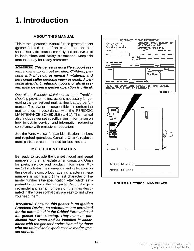
Be ready to provide the genset model and serialnumbers on the nameplate when contacting Onanfor parts, service and product information. Fig-ure 1-1 illustrates the nameplate and its location onthe side of the control box. Every character in thesenumbers is significant. (The last character of themodel number is the specification letter, which is im-portant for obtaining the right parts.)Record the gen-set model and serial numbers on the lines desig-nated in the figure so that they are easy to find whenyou need them.
WARNING Because this genset is an IgnitionProtected Device, no substitutes are permittedfor the parts listed in the Critical Parts Index ofthe genset Parts Catalog. They must be pur-chased from Onan and be installed in accor-dance with the genset Service Manual by thosewho are trained and experienced in marine gen-set service.
MODEL NUMBER: ______________________
SERIAL NUMBER: ______________________
FIGURE 1-1. TYPICAL NAMEPLATE
1-2
HOW TO OBTAIN SERVICE
WARNING Improper service or replacement ofparts can lead to severe personal injury or deathand to damage to equipment and property. Ser-vice personnel must be qualified to performelectrical and mechanical service.
For genset parts, service, and product information(such as the Service Manual), contact the nearestauthorized Onan distributor. You may go to Internetsite www.onan.com for information for contactingour distributors worldwide.
In North America
Call 1-800-888-ONAN for the nearest Cummins/Onan distributor in the United States or Canada.Press 1 (OPTION 1) to be automatically connected.
If you are unable to contact a distributor using theautomated service, consult the Yellow Pages. Typi-cally, our distributors are listed under:
GENERATORS – ELECTRIC
Outside North America
Call Onan Corporation at 1–763–574–5000 from7:30 AM to 4:00 PM (Central Standard Time),Monday through Friday, or fax 1–763–528–7229.
Information To Have Available
1. Model Number, including Spec Letter, and Seri-al Number (Figure 1-1).
2. Date of purchase.
3. Nature of problem (Section 5. Troubleshoot-ing).
EMISSIONS LABEL
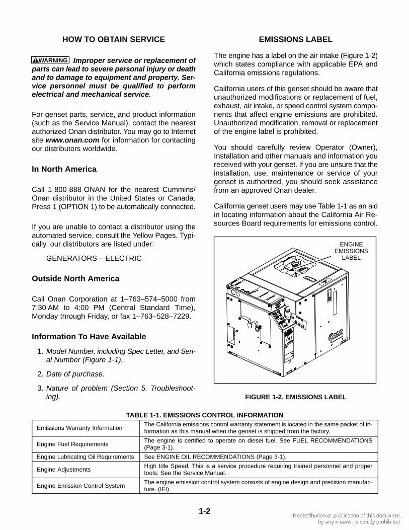
The engine has a label on the air intake (Figure 1-2)which states compliance with applicable EPA andCalifornia emissions regulations.
California users of this genset should be aware thatunauthorized modifications or replacement of fuel,exhaust, air intake, or speed control system compo-nents that affect engine emissions are prohibited.Unauthorized modification, removal or replacementof the engine label is prohibited.
You should carefully review Operator (Owner),Installation and other manuals and information youreceived with your genset. If you are unsure that theinstallation, use, maintenance or service of yourgenset is authorized, you should seek assistancefrom an approved Onan dealer.
California genset users may use Table 1-1 as an aidin locating information about the California Air Re-sources Board requirements for emissions control.
ENGINEEMISSIONS
LABEL
FIGURE 1-2. EMISSIONS LABEL
TABLE 1-1. EMISSIONS CONTROL INFORMATION
Emissions Warranty InformationThe California emissions control warranty statement is located in the same packet of in-formation as this manual when the genset is shipped from the factory.
Engine Fuel RequirementsThe engine is certified to operate on diesel fuel. See FUEL RECOMMENDATIONS(Page 3-1).
Engine Lubricating Oil Requirements See ENGINE OIL RECOMMENDATIONS (Page 3-1).
Engine AdjustmentsHigh Idle Speed. This is a service procedure requiring trained personnel and propertools. See the Service Manual.
Engine Emission Control SystemThe engine emission control system consists of engine design and precision manufac-ture. (IFI)
2-1
2. Control Panels
LOCAL CONTROL PANEL
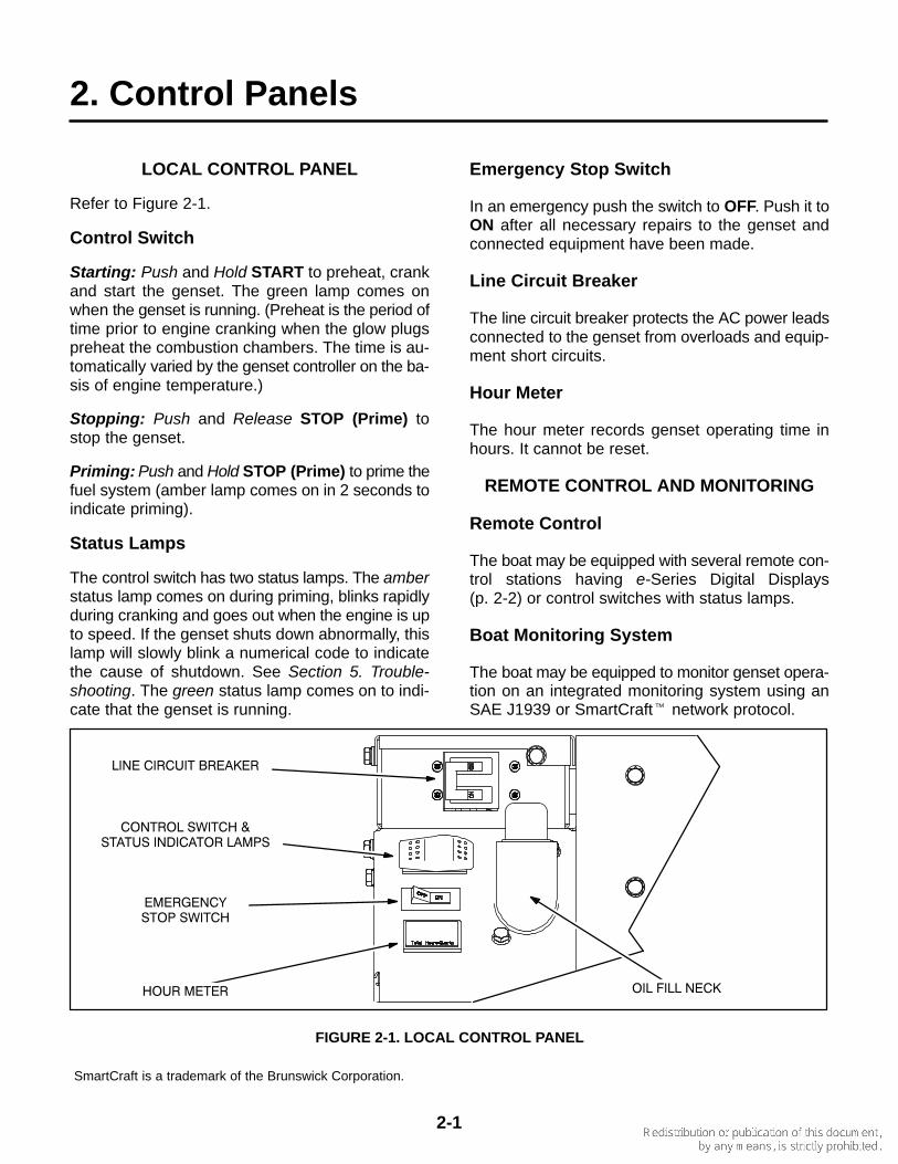
Refer to Figure 2-1.
Control Switch
Starting: Push and Hold START to preheat, crankand start the genset. The green lamp comes onwhen the genset is running. (Preheat is the period oftime prior to engine cranking when the glow plugspreheat the combustion chambers. The time is au-tomatically varied by the genset controller on the ba-sis of engine temperature.)
Stopping: Push and Release STOP (Prime) tostop the genset.
Priming: Push and Hold STOP (Prime) to prime thefuel system (amber lamp comes on in 2 seconds toindicate priming).
Status Lamps
The control switch has two status lamps. The amberstatus lamp comes on during priming, blinks rapidlyduring cranking and goes out when the engine is upto speed. If the genset shuts down abnormally, thislamp will slowly blink a numerical code to indicatethe cause of shutdown. See Section 5. Trouble-shooting. The green status lamp comes on to indi-cate that the genset is running.
Emergency Stop Switch
In an emergency push the switch to OFF. Push it toON after all necessary repairs to the genset andconnected equipment have been made.
Line Circuit Breaker
The line circuit breaker protects the AC power leadsconnected to the genset from overloads and equip-ment short circuits.
Hour Meter
The hour meter records genset operating time inhours. It cannot be reset.
REMOTE CONTROL AND MONITORING
Remote Control
The boat may be equipped with several remote con-trol stations having e-Series Digital Displays(p. 2-2) or control switches with status lamps.
Boat Monitoring System
The boat may be equipped to monitor genset opera-tion on an integrated monitoring system using anSAE J1939 or SmartCraft� network protocol.
������������
������������ ���
���������������
���������������������
��������
�����������
��������
FIGURE 2-1. LOCAL CONTROL PANEL
SmartCraft is a trademark of the Brunswick Corporation.
2-2
DIGITAL DISPLAY
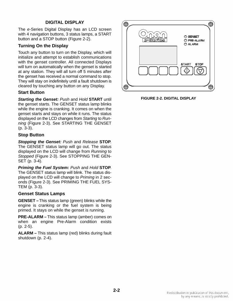
The e-Series Digital Display has an LCD screenwith 4 navigation buttons, 3 status lamps, a STARTbutton and a STOP button (Figure 2-2).
Turning On the DisplayTouch any button to turn on the Display, which willinitialize and attempt to establish communicationswith the genset controller. All connected Displayswill turn on automatically when the genset is startedat any station. They will all turn off 5 minutes afterthe genset has received a normal command to stop.They will stay on indefinitely until a fault shutdown iscleared by touching any button on any Display.
Start Button
Starting the Genset: Push and Hold START untilthe genset starts. The GENSET status lamp blinkswhile the engine is cranking. It comes on when thegenset starts and stays on while it runs. The statusdisplayed on the LCD changes from Starting to Run-ning (Figure 2-3). See STARTING THE GENSET(p. 3-3).
Stop Button
Stopping the Genset: Push and Release STOP.The GENSET status lamp will go out. The statusdisplayed on the LCD will change from Running toStopped (Figure 2-3). See STOPPING THE GEN-SET (p. 3-4).
Priming the Fuel System: Push and Hold STOP.The GENSET status lamp will blink. The status dis-played on the LCD will change to Priming in 2 sec-onds (Figure 2-3). See PRIMING THE FUEL SYS-TEM (p. 3-3).
Genset Status Lamps
GENSET – This status lamp (green) blinks while theengine is cranking or the fuel system is beingprimed. It stays on while the genset is running.
PRE-ALARM – This status lamp (amber) comes onwhen an engine Pre-Alarm condition exists(p. 2-5).
ALARM – This status lamp (red) blinks during faultshutdown (p. 2-4).
FIGURE 2-2. DIGITAL DISPLAY
2-3
Genset Status
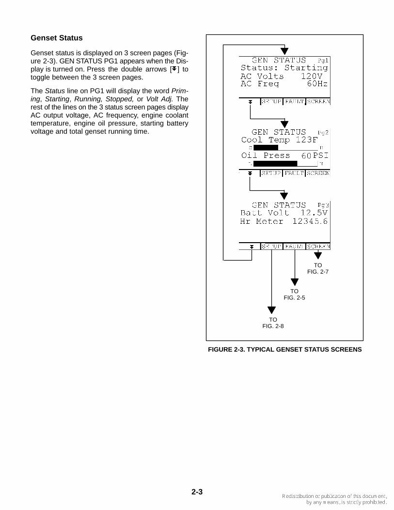
Genset status is displayed on 3 screen pages (Fig-ure 2-3). GEN STATUS PG1 appears when the Dis-play is turned on. Press the double arrows [ ] totoggle between the 3 screen pages.
The Status line on PG1 will display the word Prim-ing, Starting, Running, Stopped, or Volt Adj. Therest of the lines on the 3 status screen pages displayAC output voltage, AC frequency, engine coolanttemperature, engine oil pressure, starting batteryvoltage and total genset running time.
TOFIG. 2-7
TOFIG. 2-5
TOFIG. 2-8
FIGURE 2-3. TYPICAL GENSET STATUS SCREENS
2-4
Fault Screen
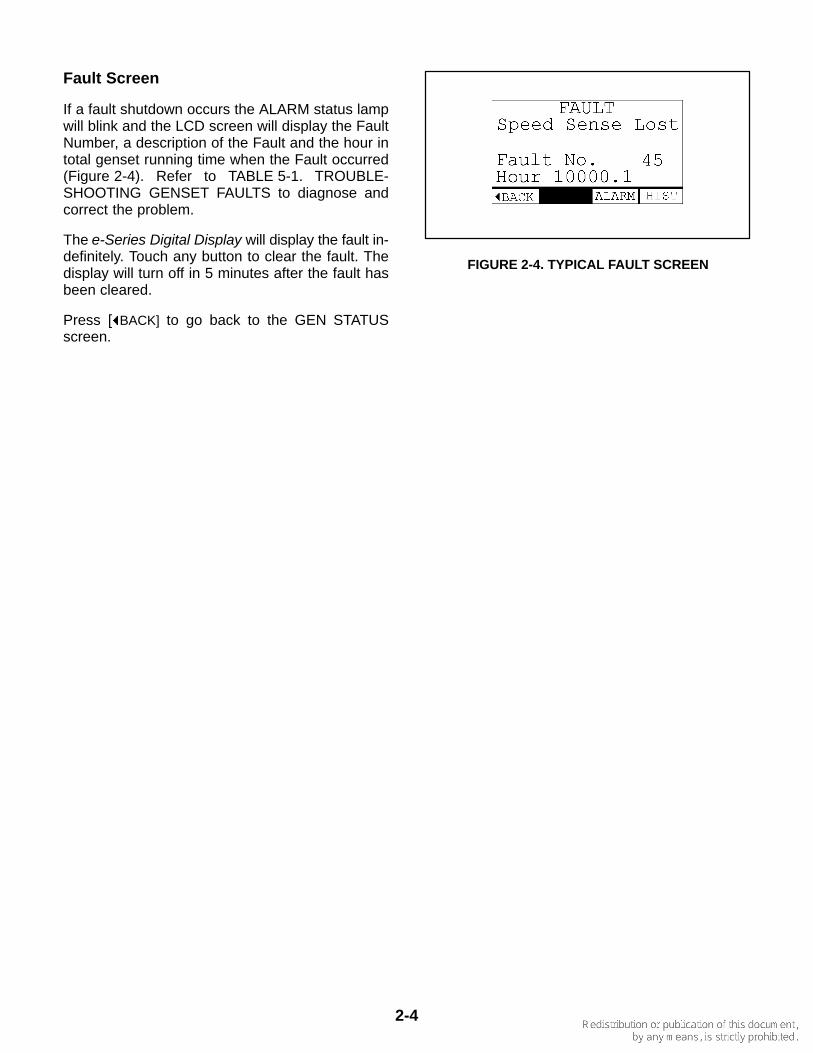
If a fault shutdown occurs the ALARM status lampwill blink and the LCD screen will display the FaultNumber, a description of the Fault and the hour intotal genset running time when the Fault occurred(Figure 2-4). Refer to TABLE 5-1. TROUBLE-SHOOTING GENSET FAULTS to diagnose andcorrect the problem.
The e-Series Digital Display will display the fault in-definitely. Touch any button to clear the fault. Thedisplay will turn off in 5 minutes after the fault hasbeen cleared.
Press [ BACK] to go back to the GEN STATUSscreen.
FIGURE 2-4. TYPICAL FAULT SCREEN

2-5
Fault History
To display any of the last five faults, press the FAULTbutton on any GEN STATUS screen. Then press theHIST button on the FAULT screen (Figure 2-5).
The FAULT HISTORY screen will display the lastFault Number, a description of the Fault and thehour in total genset running time when the fault oc-curred. Press the double arrows [ ] to toggle be-tween the last 5 faults. If there are no faults, theFAULT HISTORY screen will display No StoredFaults.
Press [ BACK] to go back to GEN STATUS.
Engine Pre-Alarms
The PRE-ALARM status lamp will start to blinkwhen engine oil pressure or temperature ap-proaches its limit for engine shutdown. The Displaywill display Low Oil Pressure or High Engine Tem-perature on the PRE-ALARM screen (Figure 2-6).
Press [ BACK] to go back to GEN STATUS to moni-tor the engine temperature or oil pressure.
Service the genset as required.
OR
FROM FAULT,FIG. 2-3
FIGURE 2-5. FAULT HISTORY
FROM FAULT,FIG. 2-3
OR
FIGURE 2-6. ENGINE PRE-ALARMS
2-6
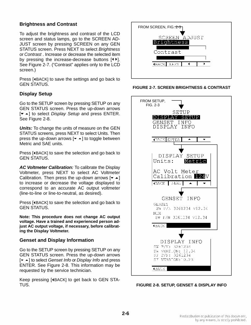
Brightness and Contrast
To adjust the brightness and contrast of the LCDscreen and status lamps, go to the SCREEN AD-JUST screen by pressing SCREEN on any GENSTATUS screen. Press NEXT to select Brightnessor Contrast . Increase or decrease the selected itemby pressing the increase-decrease buttons [ ].See Figure 2-7. (“Contrast” applies only to the LCDscreen.)
Press [ BACK] to save the settings and go back toGEN STATUS.
Display Setup
Go to the SETUP screen by pressing SETUP on anyGEN STATUS screen. Press the up-down arrows[ ] to select Display Setup and press ENTER.See Figure 2-8.
Units: To change the units of measure on the GENSTATUS screens, press NEXT to select Units. Thenpress the up-down arrows [ ] to toggle betweenMetric and SAE units.
Press [ BACK] to save the selection and go back toGEN STATUS.
AC Voltmeter Calibration: To calibrate the DisplayVoltmeter, press NEXT to select AC VoltmeterCalibration. Then press the up-down arrows [ ]to increase or decrease the voltage displayed tocorrespond to an accurate AC output voltmeter(line-to-line or line-to-neutral, as desired).
Press [ BACK] to save the selection and go back toGEN STATUS.
Note: This procedure does not change AC outputvoltage. Have a trained and experienced person ad-just AC output voltage, if necessary, before calibrat-ing the Display Voltmeter.
Genset and Display Information
Go to the SETUP screen by pressing SETUP on anyGEN STATUS screen. Press the up-down arrows[ ] to select Genset Info or Display Info and pressENTER. See Figure 2-8. This information may berequested by the service technician.
Keep pressing [ BACK] to get back to GEN STA-TUS.
FROM SCREEN, FIG. 2-3
FIGURE 2-7. SCREEN BRIGHTNESS & CONTRAST
FROM SETUP,FIG. 2-3
FIGURE 2-8. SETUP, GENSET & DISPLAY INFO
3-1
3. Operation
FUEL
WARNING Diesel fuel is combustible and cancause severe personal injury or death. Do notsmoke near fuel tanks or fuel-burning equip-ment or in areas sharing ventilation with suchequipment. Keep flames, sparks, pilot flames,electrical arcs and switches and all othersources of ignition well away. Keep a multi-class ABC fire extinguisher handy.
High quality Grade 2-D diesel fuel is necessary forgood performance and long engine life. Diesel fuelsspecified by EN 590 or ASTM D975 are recom-mended. Use Grade 1-D diesel fuel if the fuel tank isexposed to temperatures below 40° F (5° C).
The Cetane number should not be less than 45 andsulfur content not more than 0.5 percent (by weight).Where fuel is exposed to cold ambient tempera-tures, use fuel that has a cloud point (temperature atwhich wax crystals begin to form) at least 10° F(6° C) degrees below the lowest expected fuel tem-perature.
Fuel lubricity should pass a minimum load level of3100 grams as measured by ASTM D6078 or maxi-mum scar diameter of 0.45 mm as measured byASTM D6079 or ISO 12156-1.
ENGINE OIL
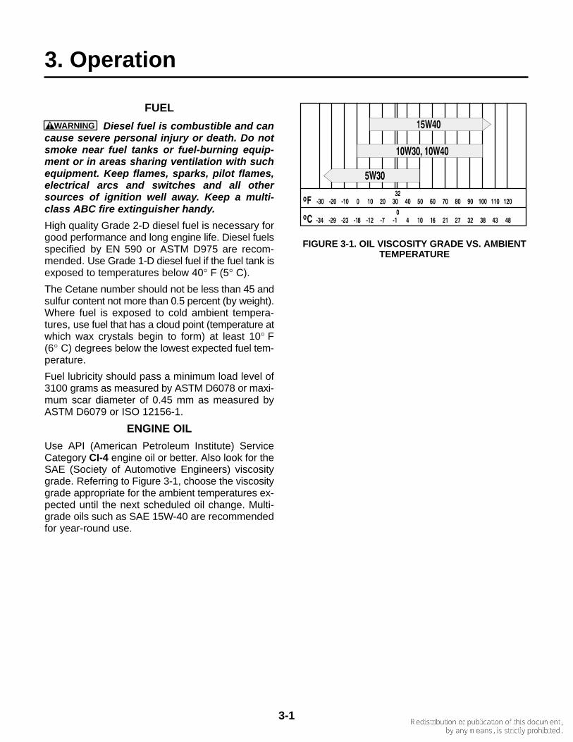
Use API (American Petroleum Institute) ServiceCategory CI-4 engine oil or better. Also look for theSAE (Society of Automotive Engineers) viscositygrade. Referring to Figure 3-1, choose the viscositygrade appropriate for the ambient temperatures ex-pected until the next scheduled oil change. Multi-grade oils such as SAE 15W-40 are recommendedfor year-round use.
FIGURE 3-1. OIL VISCOSITY GRADE VS. AMBIENTTEMPERATURE
3-2
ENGINE COOLANT
Use the best quality ethylene glycol antifreeze solu-tion available. It should be fully formulated with rustinhibitors and coolant stabilizers. A 50/50 mixture ofwater and ethylene glycol is recommended to pro-vide protection from freezing down to -34° F(-37° C).
Use fresh water that is low in minerals and corrosivechemicals for the coolant mixture. Distilled water isbest.
See Section 6. Specifications regarding coolant ca-pacity.
WARNING Ethylene Glycol antifreeze is con-sidered toxic. Dispose of it according to localregulations for hazardous substances.
BATTERIES
Reliable genset starting and starter service life de-pend upon adequate battery system capacity andmaintenance. See MAINTAINING THE BATTERYAND BATTERY CONNECTIONS (p. 4-2) and Sec-tion 6. Specifications.
FIRE EXTINGUISHER PORT
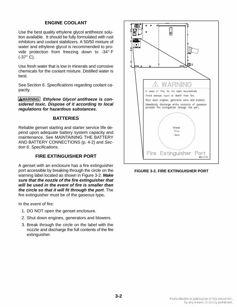
A genset with an enclosure has a fire extinguisherport accessible by breaking through the circle on thewarning label located as shown in Figure 3-2. Makesure that the nozzle of the fire extinguisher thatwill be used in the event of fire is smaller thanthe circle so that it will fit through the port. Thefire extinguisher must be of the gaseous type.
In the event of fire:
1. DO NOT open the genset enclosure.
2. Shut down engines, generators and blowers.
3. Break through the circle on the label with thenozzle and discharge the full contents of the fireextinguisher.
FIGURE 3-2. FIRE EXTINGUISHER PORT
3-3
WARNING EXHAUST GAS IS DEADLY. Allengine exhaust contains carbon monoxide; anodorless, colorless, poisonous gas that cancause unconsciousness and death. Symptomsof carbon monoxide poisoning include:
• Dizziness • Headache • Nausea • Weakness and Sleepiness• Vomiting • Inability to Think Coherently
GET EVERYONE OUT INTO FRESH AIR IMMEDI-ATELY IF ANYONE EXPERIENCES ANY OFTHESE SYMPTOMS. Seek medical attention ifsymptoms persist. Never sleep in the boat whenthe genset is running, unless the cabin has aworking carbon monoxide detector.
Look over the entire exhaust system and listenfor leaks every time you start up the genset andafter every eight hours of operation. Shut downthe genset immediately if there is a leak. Do notrun the genset until the leak has been repaired.The exhaust system must be installed in accor-dance with the genset Installation Manual.
PRE-START CHECKS
Before the first start of the day and after every eighthours of operation, inspect the genset as instructedunder GENERAL INSPECTION (p. 4-2). Keep a logof maintenance and the hours run and perform anymaintenance that may be due. See Returning theGenset to Service (p. 3-6) if the boat has been instorage. Before each start:
1. Make sure all CO detectors on board are work-ing properly.
2. Check for swimmers that might be exposed tothe engine exhaust.
3. Disconnect all electrical loads and disengagethe PTO (if so equipped).
PRIMING THE FUEL SYSTEM
The fuel system should be primed after replacingthe fuel filter or running the genset out of fuel. Toprime the fuel system, Push and Hold STOP on thee-Series Digital Display or STOP (Prime) on thecontrol switch for at least 30 seconds.
STARTING THE GENSET
The genset can be started and stopped from thegenset control panel or remote control panel.
1. Push and Hold START on the e-Series DigitalDisplay or control switch until the genset starts.The genset status lamp blinks when the engineis cranking and comes on and stays on whenthe genset starts and runs. The status dis-played on the e-Series Digital Display changesfrom Starting to Running (Figure 2-3).
2. For longer engine life, let the engine warm upfor two minutes before connecting air condi-tioners and other large electrical loads or en-gaging the PTO (if so equipped).
3. Check for water, coolant, fuel and exhaustleaks. Stop the genset immediately if there is aleak. Repair fuel leaks immediately.
4. Monitor generator set status using the e-SeriesDigital Display (p. 2-3), if so equipped. Performmaintenance or service as necessary if the Dis-play indicates a Pre-Alarm condition (p 2-2).
5. If the genset fails to start, cranking will dis-continue in 20 to 60 seconds, depending on en-gine temperature. The e-Series Digital Displayand/or control switch status lamp will indicateFault Code No. 4. See Troubleshooting(Sec. 5) if the genset does not start after sever-al tries.
CAUTION Do not continue cranking andrisk burning out the starter or flooding theengine (exhaust flow during cranking is toolow to expel water from a wet exhaust sys-tem). Find out why the genset does not startand make necessary repairs.
6. If the genset shuts down, the e-Series DigitalDisplay and/or control switch status lamp willindicate the numeric fault code. See Trouble-shooting (Sec. 5).
3-4
STOPPING THE GENSET
Disconnect all electrical loads and disengage thePTO (if so equipped) to let the genset run withoutload and cool down. After 2 minutes Push and Re-lease STOP on the e-Series Digital Display or con-trol switch. The genset status lamps will go out.
EMERGENCY STOP
Push the EMERGENCY STOP SWITCH to OFF(p. 2-1). After all necessary repairs have beenmade, push the switch to ON so that the genset canbe operated.
LOADING THE GENSET
How much equipment load can be powered de-pends upon the genset power rating. The genset willshut down or its AC output circuit breakers will trip ifthe sum of the loads exceeds genset power or cir-cuit breaker rating.
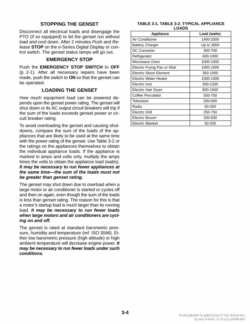
To avoid overloading the genset and causing shut-downs, compare the sum of the loads of the ap-pliances that are likely to be used at the same timewith the power rating of the genset. Use Table 3-2 orthe ratings on the appliances themselves to obtainthe individual appliance loads. If the appliance ismarked in amps and volts only, multiply the ampstimes the volts to obtain the appliance load (watts).It may be necessary to run fewer appliances atthe same time—the sum of the loads must notbe greater than genset rating.
The genset may shut down due to overload when alarge motor or air conditioner is started or cycles offand then on again, even though the sum of the loadsis less than genset rating. The reason for this is thata motor’s startup load is much larger than its runningload. It may be necessary to run fewer loadswhen large motors and air conditioners are cycl-ing on and off.
The genset is rated at standard barometric pres-sure, humidity and temperature (ref. ISO 3046). Ei-ther low barometric pressure (high altitude) or highambient temperature will decrease engine power. Itmay be necessary to run fewer loads under suchconditions.
TABLE 3-1. TABLE 3-2. TYPICAL APPLIANCELOADS
Appliance Load (watts)
Air Conditioner 1400-2000
Battery Charger Up to 3000
DC Converter 300-700
Refrigerator 600-1000
Microwave Oven 1000-1500
Electric Frying Pan or Wok 1000-1500
Electric Stove Element 350-1000
Electric Water Heater 1000-1500
Electric Iron 500-1200
Electric Hair Dryer 800-1500
Coffee Percolator 550-750
Television 200-600
Radio 50-200
Electric Drill 250-750
Electric Broom 200-500
Electric Blanket 50-200
3-5
NO-LOAD OPERATION
Keep no-load operation to a minimum. Duringno-load operation cylinder temperatures drop to thepoint where fuel does not burn completely, causingfuel wetting and white smoke. It is best to run thegenset at 1/4 to 3/4 load.
RESETTING LINE CIRCUIT BREAKERS
If the genset line circuit breaker trips (p. 2-1), or acircuit breaker in the power distribution panel of theboat, either a circuit shorted or too many loads wereconnected. Note that the genset will continue to runafter a line circuit breaker trips.
If a circuit breaker trips, disconnect or turn off asmany loads as possible and reset the circuit break-er. If the circuit breaker trips right away, either theelectrical distribution system has a short or the cir-cuit breaker is faulty. Call a qualified electrician.
If the circuit breaker does not trip, reconnect loadsone-by-one up to a total load that does not overloadthe genset or cause the circuit breaker to trip. Thecircuit probably has a short if the circuit breaker tripsright away when it is connected.
Electrical equipment must be used and maintainedproperly and be properly grounded to cause the linecircuit breakers to trip when short circuits occur.
WARNING Short circuits in electrical equip-ment can cause fire and electrical shock leadingto severe personal injury or death. Electricalequipment and its grounding must be main-tained properly to protect against short circuits.
CONNECTING TO SHORE POWER
When provisions have been made for connectingshore power, the boat must have an approved de-vice to keep the genset and shore power from beinginterconnected.
WARNING Interconnecting the genset andshore power can lead to electrocution of utilityline workers, equipment damage and fire. Usean approved switching device to prevent inter-connections.
COLD TEMPERATURE OPERATION
Do not let raw water freeze in the heat exchangerduring cold weather when the genset is not operat-ing. Freezing water can damage the raw watertubes in the heat exchanger. Engine coolant, but notraw water, is protected from freezing. If freezingtemperatures are expected, see Heat Exchangerunder Periodic Maintenance (p. 4-12). Also drainthe muffler.
CARE OF NEW OR RE-BUILT ENGINE
Avoid no-load operation as much as possible duringbreak-in. Change the oil and oil filter after the first 50hours of operation (p. 4-4).
EXERCISING THE GENSET
Exercise the genset at least 1 hour every month ifuse is infrequent. Run the genset at 1/4 to 3/4 load.A single exercise period is better than several short-er periods. Exercising a genset drives off moisture,re-lubricates the engine, uses up fuel before it be-comes stale and removes oxides from electricalcontacts. The result is better starting, more reliableoperation and longer engine life.
3-6
STORING THE GENSET
Proper storage is essential for preserving top gen-set performance and reliability when the gensetcannot be exercised regularly and will be idle formore than 120 days.
Storing the Genset
1. Turn off the genset line circuit breaker (p. 2-1).
2. Change the engine oil and filter and attach a tagindicating oil viscosity. See ENGINE OIL REC-OMMENDATIONS (p. 3-1).
3. Crank the engine several revolutions but do notlet it start. This will fill the oil passages with thenew oil.
4. Disconnect the battery cables (negative [–]cable first) from the starting battery and storethe battery according to the battery manufac-turer’s recommendations. See MAINTAININGTHE BATTERY AND BATTERY CONNEC-TIONS (p. 4-2).
5. Check coolant level and add as necessary(p. 4-6). Test the coolant mixture if freezingtemperatures are possible and change if nec-essary.
WARNING Hot coolant is under pressureand can cause severe burns when loosen-ing the pressure cap. Let the engine coolbefore loosening the pressure cap.
6. If freezing temperatures are expected, seeHeat Exchanger under Periodic Maintenance(p. 4-12). Also drain the muffler.
7. Clean and lightly oil parts that can rust.
Returning the Genset to Service
1. Check the oil tag on the genset and change theoil if the viscosity indicated is not appropriate forthe temperatures expected. See ENGINE OILRECOMMENDATIONS (p. 3-1).
2. Reconnect the starting battery (negative [–]cable last). See MAINTAINING THE BATTERYAND BATTERY CONNECTIONS (p. 4-2).
3. Replace the raw water pump impeller if it wasinstalled more than a year ago (p. 4-10).
4. Perform the maintenance required (p. 4-1),conduct the pre-start checks and prime the fuelsystem.
5. Start and run the genset.
6. Turn on the genset line circuit breaker (p. 2-1)when ready to power loads.
4-1
4. Periodic Maintenance
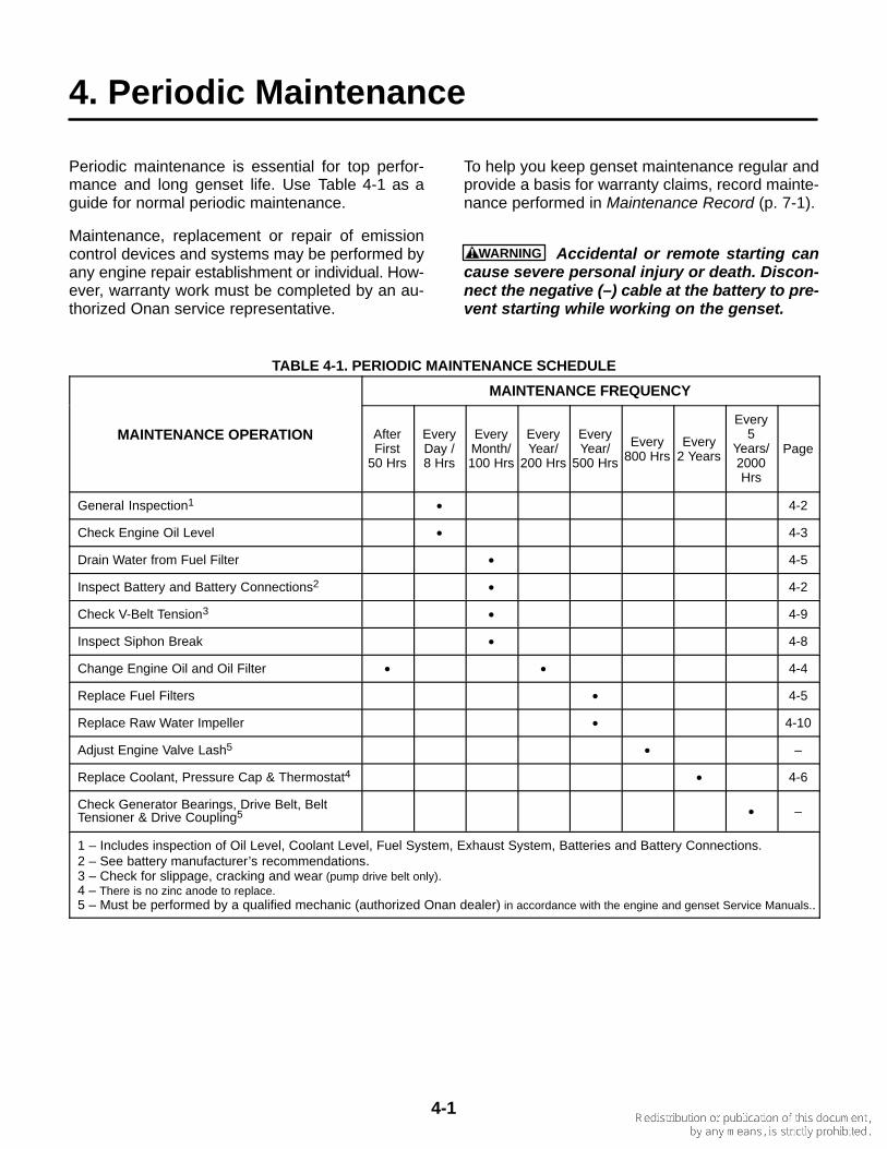
Periodic maintenance is essential for top perfor-mance and long genset life. Use Table 4-1 as aguide for normal periodic maintenance.
Maintenance, replacement or repair of emissioncontrol devices and systems may be performed byany engine repair establishment or individual. How-ever, warranty work must be completed by an au-thorized Onan service representative.
To help you keep genset maintenance regular andprovide a basis for warranty claims, record mainte-nance performed in Maintenance Record (p. 7-1).
WARNING Accidental or remote starting cancause severe personal injury or death. Discon-nect the negative (–) cable at the battery to pre-vent starting while working on the genset.
TABLE 4-1. PERIODIC MAINTENANCE SCHEDULE
MAINTENANCE FREQUENCY
MAINTENANCE OPERATION AfterFirst
50 Hrs
EveryDay /8 Hrs
EveryMonth/100 Hrs
EveryYear/
200 Hrs
EveryYear/
500 Hrs
Every800 Hrs
Every2 Years
Every5
Years/2000Hrs
Page
General Inspection1 • 4-2
Check Engine Oil Level • 4-3
Drain Water from Fuel Filter • 4-5
Inspect Battery and Battery Connections2 • 4-2
Check V-Belt Tension3 • 4-9
Inspect Siphon Break • 4-8
Change Engine Oil and Oil Filter • • 4-4
Replace Fuel Filters • 4-5
Replace Raw Water Impeller • 4-10
Adjust Engine Valve Lash5 • –
Replace Coolant, Pressure Cap & Thermostat4 • 4-6
Check Generator Bearings, Drive Belt, BeltTensioner & Drive Coupling5 • –
1 – Includes inspection of Oil Level, Coolant Level, Fuel System, Exhaust System, Batteries and Battery Connections.2 – See battery manufacturer’s recommendations.3 – Check for slippage, cracking and wear (pump drive belt only).4 – There is no zinc anode to replace.5 – Must be performed by a qualified mechanic (authorized Onan dealer) in accordance with the engine and genset Service Manuals..
4-2
GENERAL INSPECTION
Inspect the genset before the first start of the dayand after every eight hours of operation.
Oil Level
Check engine oil level (p. 4-3).
Exhaust System
Inspect the exhaust system for leaks and loosehose clamps at the exhaust manifold, exhaust el-bow, muffler, water separator and hull fittings. Re-place damaged sections of exhaust hose.
Check that all CO monitors are working properly.
WARNING EXHAUST GAS IS DEADLY! Do notoperate the genset until all exhaust leaks havebeen repaired.
Fuel System
Check for leaks at hose, tube and pipe fittings in thefuel supply and return systems while the genset isrunning and while it is stopped. Check flexible fuelhose for cuts, cracks, abrasions and loose hoseclamps. Make sure fuel lines do not rub against oth-er parts. Replace worn or damaged fuel line partsbefore leaks occur. Replace hose with with USCGTYPE A1 or ISO 7840-A1 fuel hose.
Prime the fuel system if the genset ran out of fuel.
WARNING Fuel leaks can lead to fire. Repairleaks immediately. Do not run the genset if itcauses fuel to leak.
Coolant Level
Check coolant level in the recovery tank and, if nec-essary, refill to COLD when the engine is cold or toHOT when it is at normal running temperature. Therecovery tank is designed to maintain coolant level,not to fill the system. If the tank is empty, check forand repair any coolant leaks and refill the systemthrough the fill neck on the engine. See Refilling theCooling System (p. 4-6). Use the recommendedantifreeze mixture (p. 3-2).
Raw Water System
Clean out the sea water strainer if necessary andmake sure the sea cock is open for genset opera-tion. Also, when a water/exhaust separator is pro-
vided (see Installation Manual), open the sea cockfor the water drain hose.
Check for and replace hoses that leak or are dam-aged.
Battery Connections
See MAINTAINING THE BATTERY AND BATTERYCONNECTIONS.
Mechanical
Monitor generator set status using the e-Series Dig-ital Display (p. 2-3).
Look for mechanical damage and listen for unusualnoises when the genset is running. Check the gen-set mounting bolts. Check to see that the genset airinlet and outlet openings are not clogged with debrisor blocked. Keep the genset compartment clean.
MAINTAINING THE BATTERY ANDBATTERY CONNECTIONS
WARNING Arcing at battery terminals or inlight switches or other equipment, and flames orsparks, can ignite battery gas causing severepersonal injury—Ventilate battery area beforeworking on or near battery—Wear safetyglasses—Do not smoke—Switch work light ONor OFF away from battery—Stop genset and dis-connect charger before disconnecting batterycables—Disconnect negative (–) cable first andreconnect last.
Refer to Table 4-1 for scheduled battery mainte-nance, and follow the battery manufacturer’s in-structions. Have the battery charging system ser-viced if DC system voltage is consistently low orhigh.
Check the battery terminals for clean, tight connec-tions. Loose or corroded connections have highelectrical resistance which makes starting harder.Always:
1. Keep the battery case and terminals clean anddry and the terminals tight.
2. Use a battery terminal puller if the battery hasterminal posts.
3. Make sure which terminal is positive (+) andwhich is negative (–) before making batteryconnections, always removing the negative (–)cable first and reconnecting it last to reducearcing.
4-3
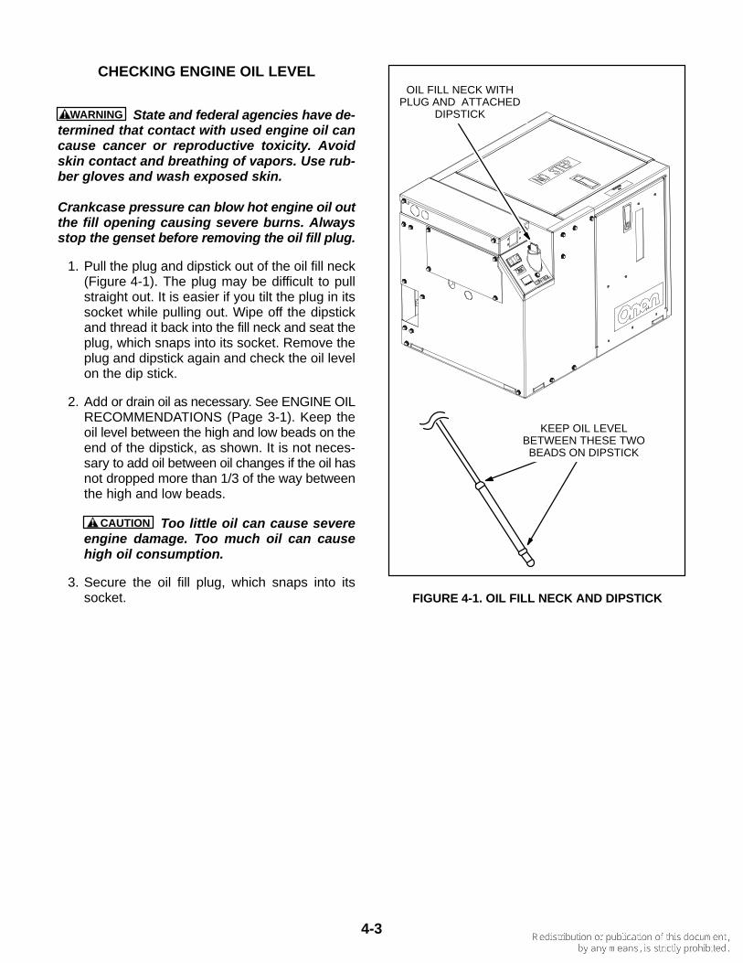
CHECKING ENGINE OIL LEVEL
WARNING State and federal agencies have de-termined that contact with used engine oil cancause cancer or reproductive toxicity. Avoidskin contact and breathing of vapors. Use rub-ber gloves and wash exposed skin.
Crankcase pressure can blow hot engine oil outthe fill opening causing severe burns. Alwaysstop the genset before removing the oil fill plug.
1. Pull the plug and dipstick out of the oil fill neck(Figure 4-1). The plug may be difficult to pullstraight out. It is easier if you tilt the plug in itssocket while pulling out. Wipe off the dipstickand thread it back into the fill neck and seat theplug, which snaps into its socket. Remove theplug and dipstick again and check the oil levelon the dip stick.
2. Add or drain oil as necessary. See ENGINE OILRECOMMENDATIONS (Page 3-1). Keep theoil level between the high and low beads on theend of the dipstick, as shown. It is not neces-sary to add oil between oil changes if the oil hasnot dropped more than 1/3 of the way betweenthe high and low beads.
CAUTION Too little oil can cause severeengine damage. Too much oil can causehigh oil consumption.
3. Secure the oil fill plug, which snaps into itssocket.
OIL FILL NECK WITHPLUG AND ATTACHED
DIPSTICK
KEEP OIL LEVELBETWEEN THESE TWO
BEADS ON DIPSTICK
FIGURE 4-1. OIL FILL NECK AND DIPSTICK
4-4
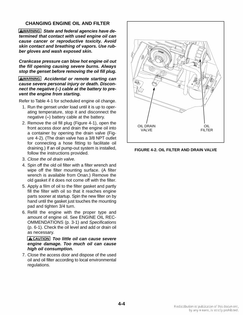
CHANGING ENGINE OIL AND FILTER
WARNING State and federal agencies have de-termined that contact with used engine oil cancause cancer or reproductive toxicity. Avoidskin contact and breathing of vapors. Use rub-ber gloves and wash exposed skin.
Crankcase pressure can blow hot engine oil outthe fill opening causing severe burns. Alwaysstop the genset before removing the oil fill plug.
WARNING Accidental or remote starting cancause severe personal injury or death. Discon-nect the negative (–) cable at the battery to pre-vent the engine from starting.
Refer to Table 4-1 for scheduled engine oil change.1. Run the genset under load until it is up to oper-
ating temperature, stop it and disconnect thenegative (–) battery cable at the battery.
2. Remove the oil fill plug (Figure 4-1), open thefront access door and drain the engine oil intoa container by opening the drain valve (Fig-ure 4-2). (The drain valve has a 3/8 NPT outletfor connecting a hose fitting to facilitate oildraining.) If an oil pump-out system is installed,follow the instructions provided.
3. Close the oil drain valve.4. Spin off the old oil filter with a filter wrench and
wipe off the filter mounting surface. (A filterwrench is available from Onan.) Remove theold gasket if it does not come off with the filter.
5. Apply a film of oil to the filter gasket and partlyfill the filter with oil so that it reaches engineparts sooner at startup. Spin the new filter on byhand until the gasket just touches the mountingpad and tighten 3/4 turn.
6. Refill the engine with the proper type andamount of engine oil. See ENGINE OIL REC-OMMENDATIONS (p. 3-1) and Specifications(p. 6-1). Check the oil level and add or drain oilas necessary.
CAUTION Too little oil can cause severeengine damage. Too much oil can causehigh oil consumption.
7. Close the access door and dispose of the usedoil and oil filter according to local environmentalregulations.
OIL DRAINVALVE
OILFILTER
FIGURE 4-2. OIL FILTER AND DRAIN VALVE
4-5
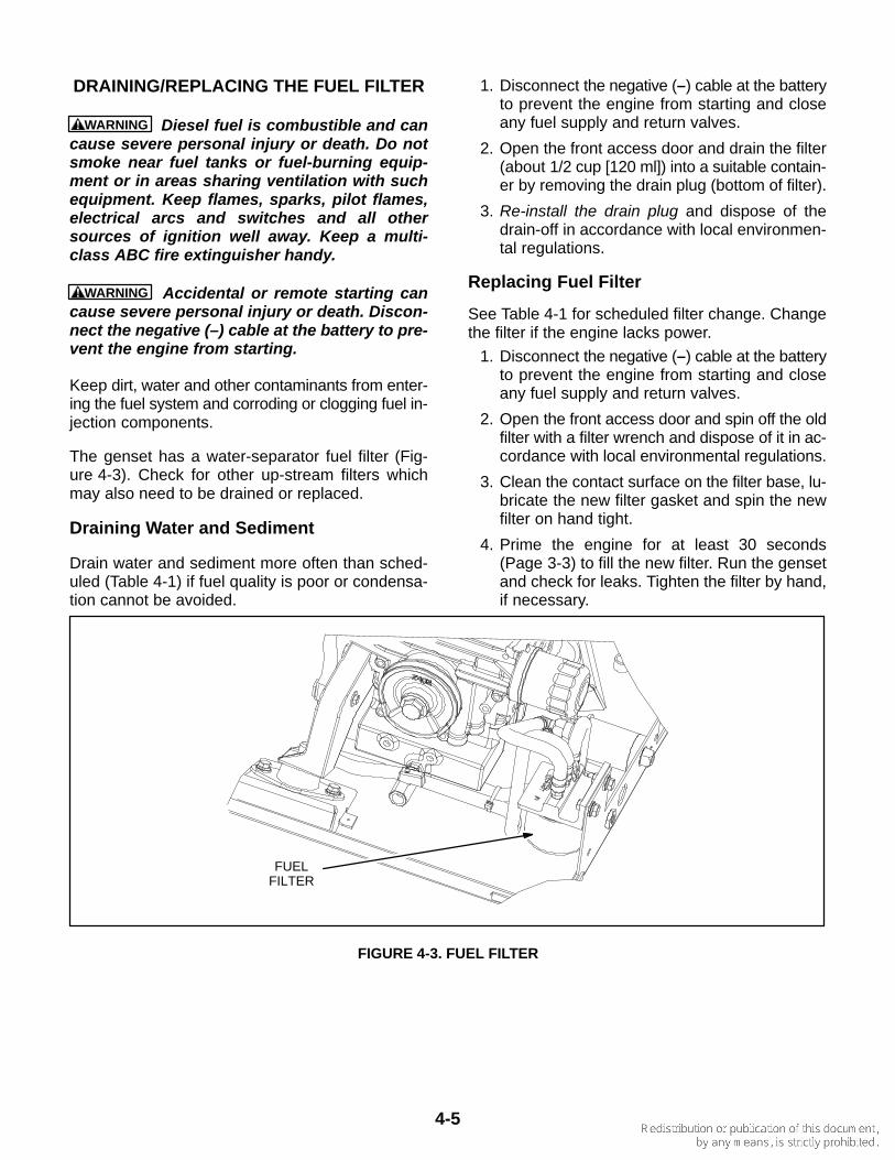
DRAINING/REPLACING THE FUEL FILTER
WARNING Diesel fuel is combustible and cancause severe personal injury or death. Do notsmoke near fuel tanks or fuel-burning equip-ment or in areas sharing ventilation with suchequipment. Keep flames, sparks, pilot flames,electrical arcs and switches and all othersources of ignition well away. Keep a multi-class ABC fire extinguisher handy.
WARNING Accidental or remote starting cancause severe personal injury or death. Discon-nect the negative (–) cable at the battery to pre-vent the engine from starting.
Keep dirt, water and other contaminants from enter-ing the fuel system and corroding or clogging fuel in-jection components.
The genset has a water-separator fuel filter (Fig-ure 4-3). Check for other up-stream filters whichmay also need to be drained or replaced.
Draining Water and Sediment
Drain water and sediment more often than sched-uled (Table 4-1) if fuel quality is poor or condensa-tion cannot be avoided.
1. Disconnect the negative (–) cable at the batteryto prevent the engine from starting and closeany fuel supply and return valves.
2. Open the front access door and drain the filter(about 1/2 cup [120 ml]) into a suitable contain-er by removing the drain plug (bottom of filter).
3. Re-install the drain plug and dispose of thedrain-off in accordance with local environmen-tal regulations.
Replacing Fuel Filter
See Table 4-1 for scheduled filter change. Changethe filter if the engine lacks power.
1. Disconnect the negative (–) cable at the batteryto prevent the engine from starting and closeany fuel supply and return valves.
2. Open the front access door and spin off the oldfilter with a filter wrench and dispose of it in ac-cordance with local environmental regulations.
3. Clean the contact surface on the filter base, lu-bricate the new filter gasket and spin the newfilter on hand tight.
4. Prime the engine for at least 30 seconds(Page 3-3) to fill the new filter. Run the gensetand check for leaks. Tighten the filter by hand,if necessary.
FUELFILTER
FIGURE 4-3. FUEL FILTER
4-6
MAINTAINING THE ENGINE COOLINGSYSTEM
Refer to Table 4-1 for scheduled maintenance.
Cooling System Overview
The engine is cooled by a pressurized, closed-loopliquid cooling system in which coolant is pumpedthrough passages in the engine block, head and ex-haust manifold (Figure 4-4). The exhaust manifoldalso serves as the engine coolant reservoir.
The heat exchanger is mounted inside the exhaustmanifold. Raw water (the flotation water) is pumpedthrough tubes in the heat exchanger to cool the en-gine coolant. The raw water then passes through ahose into the exhaust-water mixer where it cools theexhaust gases and is expelled. The V-belt drives thecoolant and the raw water pumps.
Recommended Coolant Mixture
See ENGINE COOLANT (p. 3-2) for recommenda-tions.
Replenishing Normal Coolant Loss
Check coolant level in the recovery tank before thefirst startup of each day and, if necessary, refill toCOLD when the engine is cold or to HOT when it isrunning. The recovery tank is designed to maintaincoolant level, not to fill the system. If the tank isempty, check for and repair any coolant leaks andrefill the system through the fill neck on the engine.
Make sure the two hoses from the recovery tank arerouted through the two holes in the right end of thegenset enclosure, that the coolant recovery hose isconnected to the fill neck on the engine and that theoverflow hose terminates in the drip pan where it willnot splash coolant on electrical components.
Pressure Cap
Replace the pressure cap every two years (sealsdeteriorate and leak). Proper cooling system pres-sure (10 psi) is essential for optimal engine coolingand minimal coolant loss.
Coolant Hoses
Check for and replace hoses that leak or are dam-aged.
Draining and Cleaning Cooling System
WARNING Accidental or remote starting cancause severe personal injury or death. Discon-nect the negative (–) cable from the battery toprevent the engine from starting.
Hot coolant spray can cause severe burns. Letthe engine cool before releasing the pressurecap or removing the drain cap.
1. Have towels and containers ready to wipe up,collect and properly dispose of the coolant.
2. Disconnect the negative (–) cable at the batteryto prevent the engine from starting, let the en-gine cool and remove the front and top accessdoors and the coolant pressure cap.
3. Drain the exhaust manifold/coolant reservoirby disconnecting the hose at the coolant pumpinlet (Figure 4-4) and twisting it down into acontainer.
4. Drain the block by removing the cap on thedrain fitting on the left side of the block (Fig-ure 4-4). Use an 11/16 inch socket on a swiveland 12 to 18 inch extension. To catch the cool-ant and direct it into a container, insert the sock-et and extension through a piece of hose largeenough to fit over the socket but shorter thanthe extension. The hose will catch the coolantas the cap is being unscrewed.
5. Use radiator cleaning chemicals to clean andflush the cooling system before refilling withfresh coolant. Follow the cleaner manufactur-er’s instructions.
Refilling Cooling System
Close the block drain cap and reconnect the pumpinlet hose and fill the system through the engine fillneck. The system will fill only as fast as the air canescape. Fill to the bottom of the fill neck. Start andrun the engine for a couple of minutes to dislodge airpockets and shut it down. Add as much coolant asnecessary and secure the pressure cap. Then refillthe recovery tank up to the COLD mark.
CAUTION Low coolant level can cause severeengine damage. Make sure the system is full.
Filling a hot engine with cold water can causecracks in the manifold, head and block.
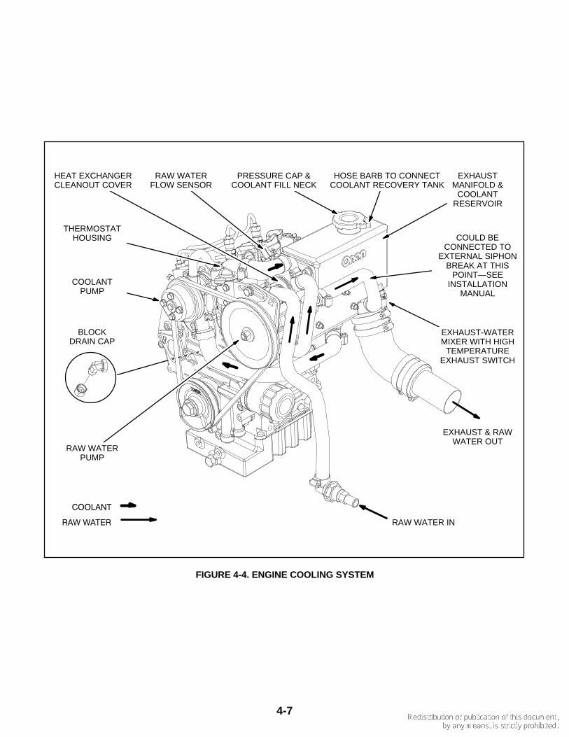
4-7
RAW WATER IN
EXHAUST & RAWWATER OUT
HOSE BARB TO CONNECTCOOLANT RECOVERY TANK
THERMOSTATHOUSING
COOLANTPUMP
BLOCKDRAIN CAP
RAW WATERPUMP
�������
�������
EXHAUSTMANIFOLD &
COOLANTRESERVOIR
EXHAUST-WATERMIXER WITH HIGH
TEMPERATUREEXHAUST SWITCH
COULD BECONNECTED TO
EXTERNAL SIPHONBREAK AT THIS
POINT—SEEINSTALLATION
MANUAL
RAW WATERFLOW SENSOR
HEAT EXCHANGERCLEANOUT COVER
PRESSURE CAP &COOLANT FILL NECK
FIGURE 4-4. ENGINE COOLING SYSTEM
4-8
Siphon Break
WARNING Bypassing a siphon break or failingto maintain it can lead to engine flooding anddamage to the engine not covered under War-ranty.
See Table 4-1 for scheduled maintenance. A siphonbreak is installed when the exhaust-water mixer isbelow the water line. If of a spring-loaded valve de-sign, check for free movement of the plunger. Re-place the device if the plunger does not move freelyor the body is encrusted with deposits from leakagepast the valve seat. If of the bleed-vent type, checkthat the vent hose is properly connected on bothends. If the vent is connected to a through-hull fit-ting, check for normal water flow whenever the en-gine is running. See the Installation Manual for moreinformation regarding siphon break installation.
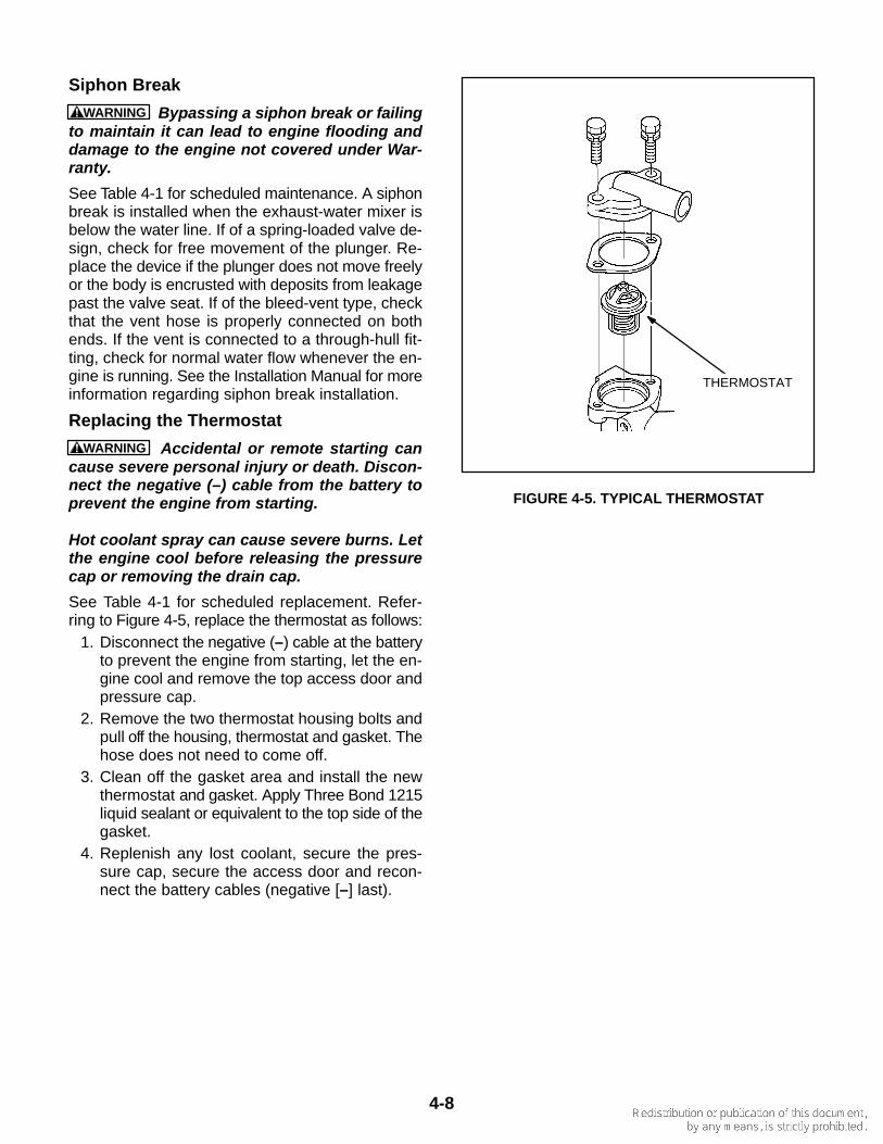
Replacing the Thermostat
WARNING Accidental or remote starting cancause severe personal injury or death. Discon-nect the negative (–) cable from the battery toprevent the engine from starting.
Hot coolant spray can cause severe burns. Letthe engine cool before releasing the pressurecap or removing the drain cap.
See Table 4-1 for scheduled replacement. Refer-ring to Figure 4-5, replace the thermostat as follows:
1. Disconnect the negative (–) cable at the batteryto prevent the engine from starting, let the en-gine cool and remove the top access door andpressure cap.
2. Remove the two thermostat housing bolts andpull off the housing, thermostat and gasket. Thehose does not need to come off.
3. Clean off the gasket area and install the newthermostat and gasket. Apply Three Bond 1215liquid sealant or equivalent to the top side of thegasket.
4. Replenish any lost coolant, secure the pres-sure cap, secure the access door and recon-nect the battery cables (negative [–] last).
THERMOSTAT
FIGURE 4-5. TYPICAL THERMOSTAT
4-9
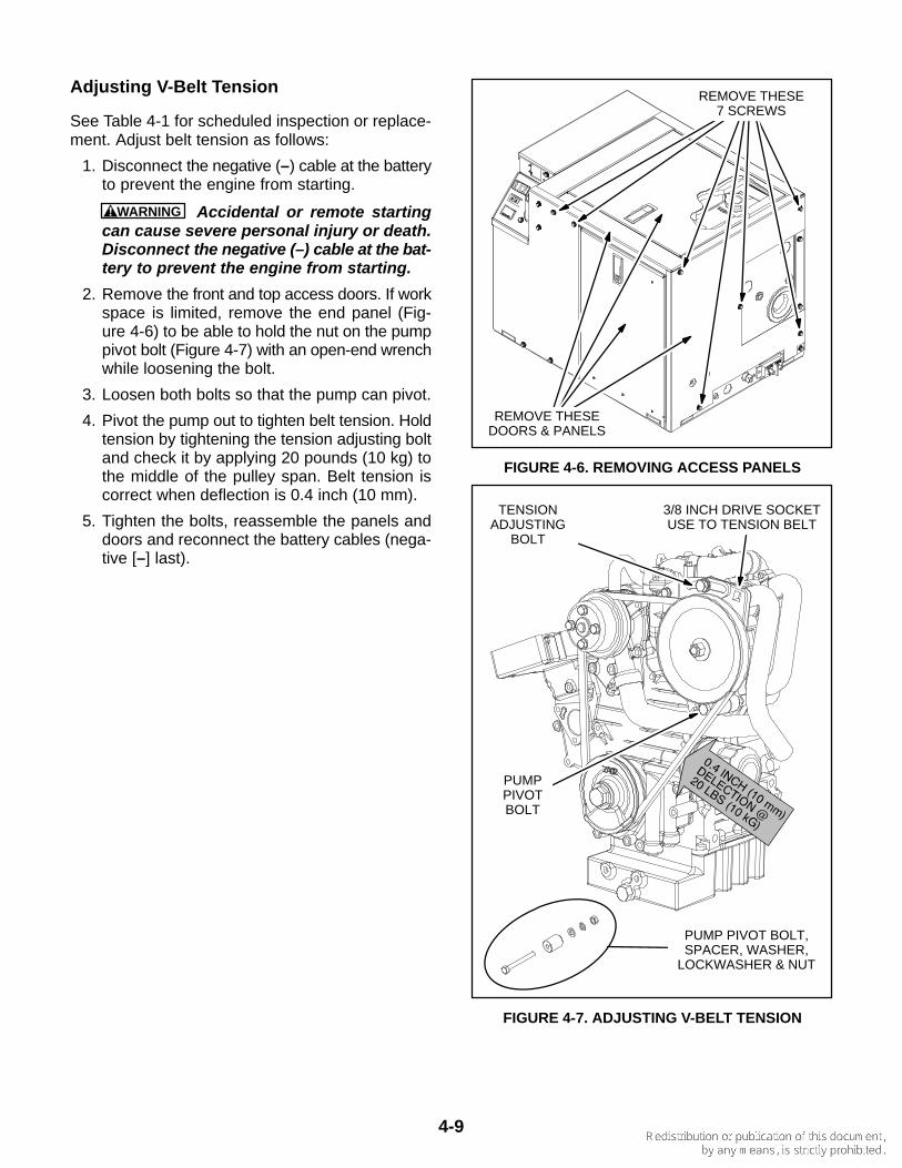
Adjusting V-Belt Tension
See Table 4-1 for scheduled inspection or replace-ment. Adjust belt tension as follows:
1. Disconnect the negative (–) cable at the batteryto prevent the engine from starting.
WARNING Accidental or remote startingcan cause severe personal injury or death.Disconnect the negative (–) cable at the bat-tery to prevent the engine from starting.
2. Remove the front and top access doors. If workspace is limited, remove the end panel (Fig-ure 4-6) to be able to hold the nut on the pumppivot bolt (Figure 4-7) with an open-end wrenchwhile loosening the bolt.
3. Loosen both bolts so that the pump can pivot.
4. Pivot the pump out to tighten belt tension. Holdtension by tightening the tension adjusting boltand check it by applying 20 pounds (10 kg) tothe middle of the pulley span. Belt tension iscorrect when deflection is 0.4 inch (10 mm).
5. Tighten the bolts, reassemble the panels anddoors and reconnect the battery cables (nega-tive [–] last).
REMOVE THESE7 SCREWS
REMOVE THESEDOORS & PANELS
FIGURE 4-6. REMOVING ACCESS PANELS
PUMPPIVOTBOLT
TENSIONADJUSTING
BOLT
3/8 INCH DRIVE SOCKETUSE TO TENSION BELT
PUMP PIVOT BOLT,SPACER, WASHER,
LOCKWASHER & NUT
FIGURE 4-7. ADJUSTING V-BELT TENSION
4-10
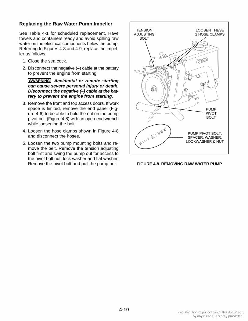
Replacing the Raw Water Pump Impeller
See Table 4-1 for scheduled replacement. Havetowels and containers ready and avoid spilling rawwater on the electrical components below the pump.Referring to Figures 4-8 and 4-9, replace the impel-ler as follows:
1. Close the sea cock.
2. Disconnect the negative (–) cable at the batteryto prevent the engine from starting.
WARNING Accidental or remote startingcan cause severe personal injury or death.Disconnect the negative (–) cable at the bat-tery to prevent the engine from starting.
3. Remove the front and top access doors. If workspace is limited, remove the end panel (Fig-ure 4-6) to be able to hold the nut on the pumppivot bolt (Figure 4-8) with an open-end wrenchwhile loosening the bolt.
4. Loosen the hose clamps shown in Figure 4-8and disconnect the hoses.
5. Loosen the two pump mounting bolts and re-move the belt. Remove the tension adjustingbolt first and swing the pump out for access tothe pivot bolt nut, lock washer and flat washer.Remove the pivot bolt and pull the pump out.
LOOSEN THESE2 HOSE CLAMPS
PUMPPIVOTBOLT
TENSIONADJUSTING
BOLT
PUMP PIVOT BOLT,SPACER, WASHER,
LOCKWASHER & NUT
FIGURE 4-8. REMOVING RAW WATER PUMP
4-11
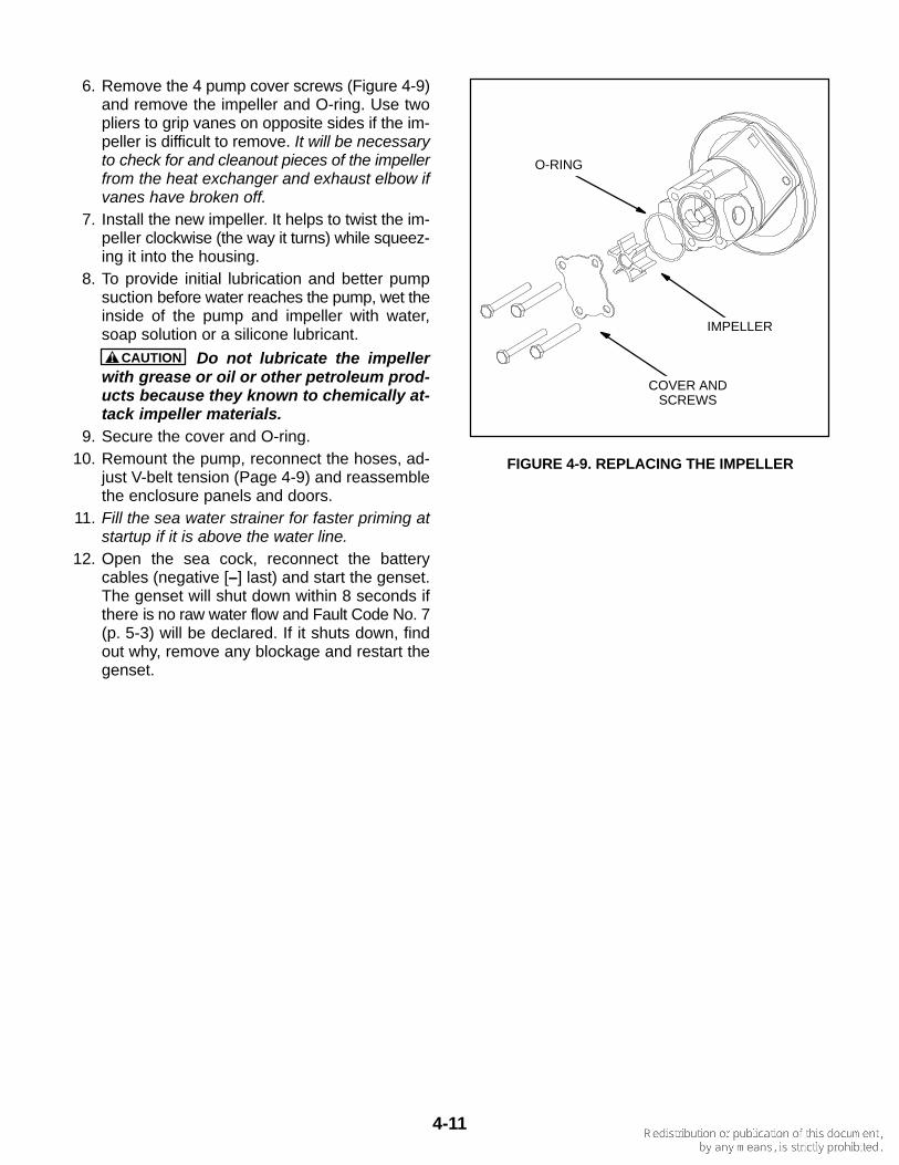
6. Remove the 4 pump cover screws (Figure 4-9)and remove the impeller and O-ring. Use twopliers to grip vanes on opposite sides if the im-peller is difficult to remove. It will be necessaryto check for and cleanout pieces of the impellerfrom the heat exchanger and exhaust elbow ifvanes have broken off.
7. Install the new impeller. It helps to twist the im-peller clockwise (the way it turns) while squeez-ing it into the housing.
8. To provide initial lubrication and better pumpsuction before water reaches the pump, wet theinside of the pump and impeller with water,soap solution or a silicone lubricant.
CAUTION Do not lubricate the impellerwith grease or oil or other petroleum prod-ucts because they known to chemically at-tack impeller materials.
9. Secure the cover and O-ring.10. Remount the pump, reconnect the hoses, ad-
just V-belt tension (Page 4-9) and reassemblethe enclosure panels and doors.
11. Fill the sea water strainer for faster priming atstartup if it is above the water line.
12. Open the sea cock, reconnect the batterycables (negative [–] last) and start the genset.The genset will shut down within 8 seconds ifthere is no raw water flow and Fault Code No. 7(p. 5-3) will be declared. If it shuts down, findout why, remove any blockage and restart thegenset.
IMPELLER
O-RING
COVER ANDSCREWS
FIGURE 4-9. REPLACING THE IMPELLER
4-12
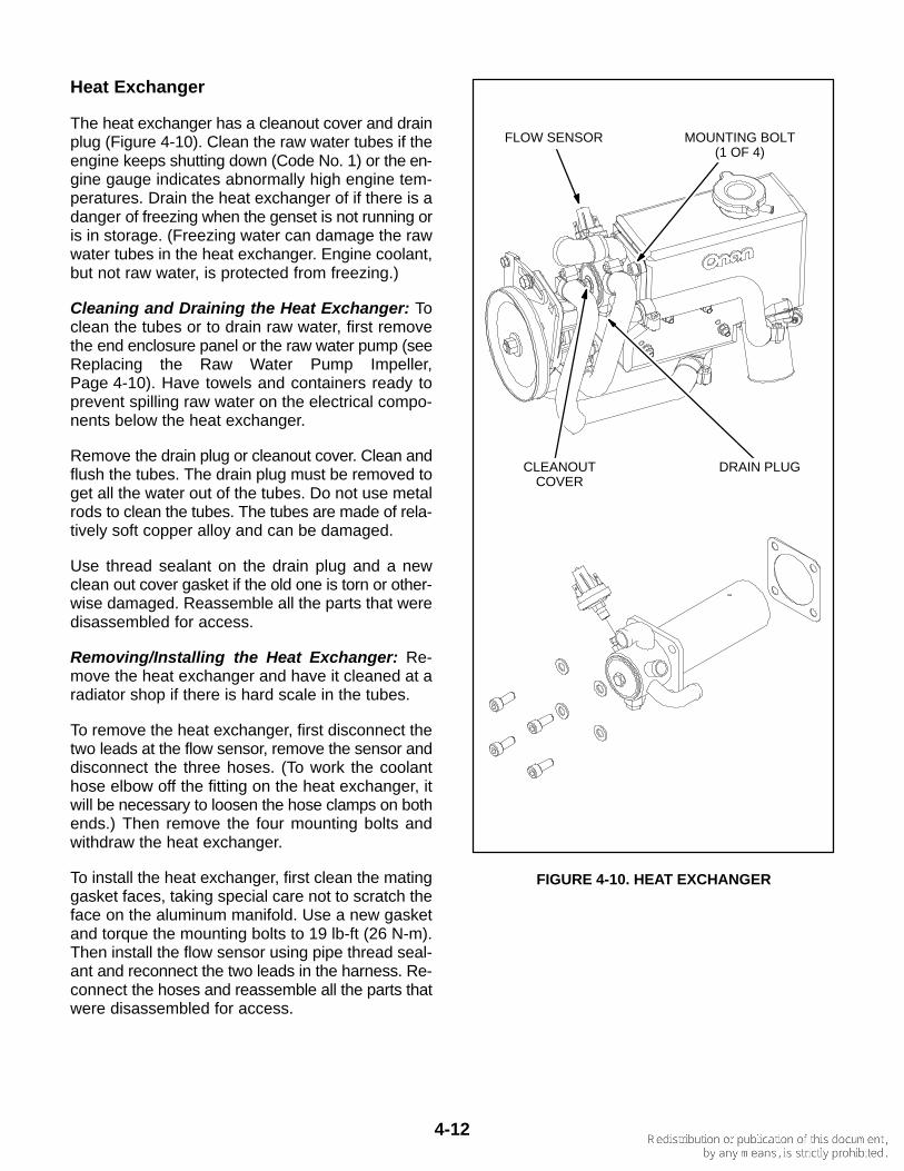
Heat Exchanger
The heat exchanger has a cleanout cover and drainplug (Figure 4-10). Clean the raw water tubes if theengine keeps shutting down (Code No. 1) or the en-gine gauge indicates abnormally high engine tem-peratures. Drain the heat exchanger of if there is adanger of freezing when the genset is not running oris in storage. (Freezing water can damage the rawwater tubes in the heat exchanger. Engine coolant,but not raw water, is protected from freezing.)
Cleaning and Draining the Heat Exchanger: Toclean the tubes or to drain raw water, first removethe end enclosure panel or the raw water pump (seeReplacing the Raw Water Pump Impeller,Page 4-10). Have towels and containers ready toprevent spilling raw water on the electrical compo-nents below the heat exchanger.
Remove the drain plug or cleanout cover. Clean andflush the tubes. The drain plug must be removed toget all the water out of the tubes. Do not use metalrods to clean the tubes. The tubes are made of rela-tively soft copper alloy and can be damaged.
Use thread sealant on the drain plug and a newclean out cover gasket if the old one is torn or other-wise damaged. Reassemble all the parts that weredisassembled for access.
Removing/Installing the Heat Exchanger: Re-move the heat exchanger and have it cleaned at aradiator shop if there is hard scale in the tubes.
To remove the heat exchanger, first disconnect thetwo leads at the flow sensor, remove the sensor anddisconnect the three hoses. (To work the coolanthose elbow off the fitting on the heat exchanger, itwill be necessary to loosen the hose clamps on bothends.) Then remove the four mounting bolts andwithdraw the heat exchanger.
To install the heat exchanger, first clean the matinggasket faces, taking special care not to scratch theface on the aluminum manifold. Use a new gasketand torque the mounting bolts to 19 lb-ft (26 N-m).Then install the flow sensor using pipe thread seal-ant and reconnect the two leads in the harness. Re-connect the hoses and reassemble all the parts thatwere disassembled for access.
DRAIN PLUGCLEANOUTCOVER
FLOW SENSOR MOUNTING BOLT(1 OF 4)
FIGURE 4-10. HEAT EXCHANGER
5-1
5. Troubleshooting
Use TABLE 5-1. TROUBLESHOOTING GENSETFAULTS in conjunction with the e-Series Digital Dis-play or blinking control switch status lamp to trouble-shoot the genset. Perform the step-by-step correc-tive actions suggested. If you are still unable to re-solve the problem, contact an authorized Onan ser-vice representative. See How to Obtain Service(p. 1-2).
Many genset shutdowns can be avoided by perform-ing periodic maintenance on schedule (TABLE 4-1.PERIODIC MAINTENANCE SCHEDULE) and by notrunning the genset out of fuel. Note that when gen-sets and propulsion engines draw from the same fueltanks, the fuel dip tubes are usually arranged so thatthe gensets run out of fuel first. By marking the gen-set empty points on the fuel gauges, it will be easierto tell when to stop the gensets before running themout of fuel.
TROUBLESHOOTING WITH DIGITALDISPLAY
If a fault shutdown occurs the ALARM status lampon the e-Series Digital Display will blink and the LCDscreen will display the Fault Number, a descriptionof the Fault and the hour in total genset running timewhen the Fault occurred (Figure 2-4).
The fault will be displayed indefinitely. Touch anybutton to clear the fault. The display will turn off in 5minutes after the fault has been cleared.
Last Five Faults: See Page 2-5 to display any ofthe last five faults in fault history.
TROUBLESHOOTING WITH STATUS LAMP
If a fault shutdown occurs, the amber status lamp onthe control switch will repeatedly blink sets of 3, 4, 5or 7 blinks.
• One blink indicates shutdown due to high en-gine temperature.
• Two blinks indicate shutdown due to low oilpressure.
• Three blinks indicate a service fault. PressStop once to cause the two-digit shutdowncode to blink. (Pressing Stop again will stop theblinking.) The two-digit code consists of 1 to 7blinks, a brief pause, and then 1 to 9 blinks. Thefirst set of blinks represents the tens digit andthe second set of blinks the units digit of theshutdown code number. For example, shut-down code No. 36 appears as:
blink-blink-blink—pause—blink-blink-blink-blink-blink-blink—
long pause—repeat
• Four blinks indicate shutdown due to a failureto start within the time allowed for cranking.
• Five blinks indicate shutdown due to high lev-els of Carbon Monoxide (CO) in the vessel.
• Seven blinks indicate shutdown due to a lossof raw water flow for engine and exhaust cool-ing.
The fault code stops blinking after five minutes.Press Stop three times within three seconds to re-store fault code blinking.
Note: The last fault logged will blink even though thecondition that caused the shutdown may have beencorrected.
5-2
TABLE 5-1. TROUBLESHOOTING GENSET FAULTS
Some genset service procedures present hazards that can result in severe personalinjury or death. Only trained and experienced service personnel with knowledge of fuels, electricity,and machinery hazards should perform genset service. See Safety Precautions.
Accidental or remote starting can cause severe personal injury or death. Before removing a panel oraccess door, disconnect the negative (–) cable from the battery to prevent the engine from starting.
WARNING
NO RESPONSE AT DIGITAL DISPLAY OR CONTROL SWITCH(Faulty switch, poor or missing connections, dead battery)
Corrective Action: 1. At the genset control panel, push the emergency stop switch On.2. Try the Digital Display or control switch on the genset (local) if there is no response at the remote
Display or control switch, and vice versa.3. Check for battery voltage at the battery cable terminals on the genset. Service as necessary by
cleaning and tightening battery cable connections, recharging or replacing the battery or replacingdamaged or missing battery cables (p. 4-2).
THE STARTER ENGAGES AND DISENGAGES(Low cranking voltage)
Corrective Action: Service as necessary by cleaning and tightening battery cable connections, re-charging or replacing the battery or replacing damaged battery cables (p. 4-2).
THE STARTING BATTERIES DO NOT MAINTAIN A CHARGE(Marginal battery, battery connections or charging system)
Corrective Action: 1. Service the battery as necessary by cleaning and tightening connections, recharging or replacing
the battery or replacing damaged battery cables (p. 4-2).2. Inspect the serpentine belt that drives the charging alternator and service as necessary (p. 4-9).
NO AC POWER WHEN GENSET IS RUNNING(A Circuit Breaker is OFF, tripped or malfunctioning or the generator is not connected properly)
Corrective Action: 1. Reset or turn ON the genset circuit breaker if OFF or tripped.2. Reset or turn ON any other circuit breaker in the AC power supply system if OFF or tripped.
HIGH ENGINE TEMPERATURE—CODE NO. 1(Engine coolant temperature exceed design limit)
Corrective Action: 1. Check for and clean a blocked sea water strainer. If above the water line, fill the strainer with water
to assist priming.2. Check engine coolant level and add coolant as necessary.3. Check for kinked or leaking hoses and reconnect, reroute or replace.4. Check the V-belt that drives the coolant pump and service as necessary (p. 4-9).5. Inspect the siphon break (if provided) for proper operation.6. Check for a worn raw water impeller and replace as necessary (p. 4-10).7. Clean the heat exchanger (p. 4-12).8. Check the bottom of the hull for any blockage at the through-hull fitting.
5-3
TABLE 5-1. TROUBLESHOOTING GENSET FAULTS (CONT.)
Some genset service procedures present hazards that can result in severe personalinjury or death. Only trained and experienced service personnel with knowledge of fuels, electricity,and machinery hazards should perform genset service. See Safety Precautions.
Accidental or remote starting can cause severe personal injury or death. Before removing a panel oraccess door, disconnect the negative (–) cable from the battery to prevent the engine from starting.
WARNING
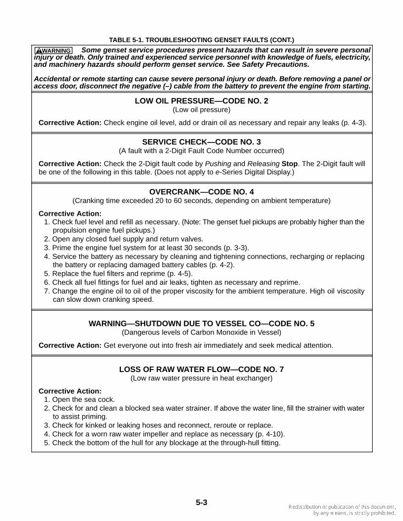
LOW OIL PRESSURE—CODE NO. 2(Low oil pressure)
Corrective Action: Check engine oil level, add or drain oil as necessary and repair any leaks (p. 4-3).
SERVICE CHECK—CODE NO. 3(A fault with a 2-Digit Fault Code Number occurred)
Corrective Action: Check the 2-Digit fault code by Pushing and Releasing Stop. The 2-Digit fault willbe one of the following in this table. (Does not apply to e-Series Digital Display.)
OVERCRANK—CODE NO. 4(Cranking time exceeded 20 to 60 seconds, depending on ambient temperature)
Corrective Action: 1. Check fuel level and refill as necessary. (Note: The genset fuel pickups are probably higher than the
propulsion engine fuel pickups.)2. Open any closed fuel supply and return valves.3. Prime the engine fuel system for at least 30 seconds (p. 3-3).4. Service the battery as necessary by cleaning and tightening connections, recharging or replacing
the battery or replacing damaged battery cables (p. 4-2).5. Replace the fuel filters and reprime (p. 4-5).6. Check all fuel fittings for fuel and air leaks, tighten as necessary and reprime.7. Change the engine oil to oil of the proper viscosity for the ambient temperature. High oil viscosity
can slow down cranking speed.
WARNING—SHUTDOWN DUE TO VESSEL CO—CODE NO. 5(Dangerous levels of Carbon Monoxide in Vessel)
Corrective Action: Get everyone out into fresh air immediately and seek medical attention.
LOSS OF RAW WATER FLOW—CODE NO. 7(Low raw water pressure in heat exchanger)
Corrective Action: 1. Open the sea cock.2. Check for and clean a blocked sea water strainer. If above the water line, fill the strainer with water
to assist priming.3. Check for kinked or leaking hoses and reconnect, reroute or replace.4. Check for a worn raw water impeller and replace as necessary (p. 4-10).5. Check the bottom of the hull for any blockage at the through-hull fitting.
5-4
TABLE 5-1. TROUBLESHOOTING GENSET FAULTS (CONT.)
Some genset service procedures present hazards that can result in severe personalinjury or death. Only trained and experienced service personnel with knowledge of fuels, electricity,and machinery hazards should perform genset service. See Safety Precautions.
Accidental or remote starting can cause severe personal injury or death. Before removing a panel oraccess door, disconnect the negative (–) cable from the battery to prevent the engine from starting.
WARNING
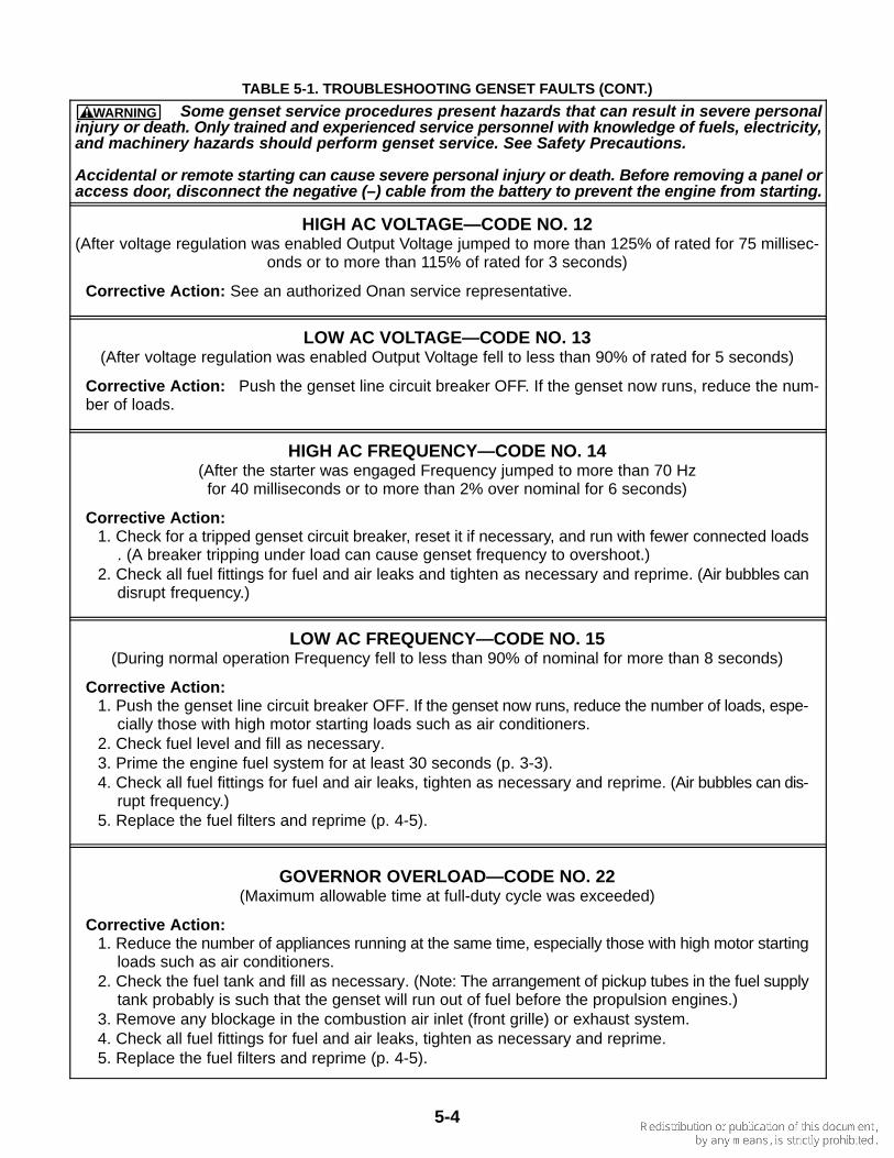
HIGH AC VOLTAGE—CODE NO. 12(After voltage regulation was enabled Output Voltage jumped to more than 125% of rated for 75 millisec-
onds or to more than 115% of rated for 3 seconds)
Corrective Action: See an authorized Onan service representative.
LOW AC VOLTAGE—CODE NO. 13(After voltage regulation was enabled Output Voltage fell to less than 90% of rated for 5 seconds)
Corrective Action: Push the genset line circuit breaker OFF. If the genset now runs, reduce the num-ber of loads.
HIGH AC FREQUENCY—CODE NO. 14(After the starter was engaged Frequency jumped to more than 70 Hz
for 40 milliseconds or to more than 2% over nominal for 6 seconds)
Corrective Action: 1. Check for a tripped genset circuit breaker, reset it if necessary, and run with fewer connected loads
. (A breaker tripping under load can cause genset frequency to overshoot.)2. Check all fuel fittings for fuel and air leaks and tighten as necessary and reprime. (Air bubbles can
disrupt frequency.)
LOW AC FREQUENCY—CODE NO. 15(During normal operation Frequency fell to less than 90% of nominal for more than 8 seconds)
Corrective Action: 1. Push the genset line circuit breaker OFF. If the genset now runs, reduce the number of loads, espe-
cially those with high motor starting loads such as air conditioners.2. Check fuel level and fill as necessary.3. Prime the engine fuel system for at least 30 seconds (p. 3-3).4. Check all fuel fittings for fuel and air leaks, tighten as necessary and reprime. (Air bubbles can dis-
rupt frequency.)5. Replace the fuel filters and reprime (p. 4-5).
GOVERNOR OVERLOAD—CODE NO. 22(Maximum allowable time at full-duty cycle was exceeded)
Corrective Action: 1. Reduce the number of appliances running at the same time, especially those with high motor starting
loads such as air conditioners.2. Check the fuel tank and fill as necessary. (Note: The arrangement of pickup tubes in the fuel supply
tank probably is such that the genset will run out of fuel before the propulsion engines.)3. Remove any blockage in the combustion air inlet (front grille) or exhaust system.4. Check all fuel fittings for fuel and air leaks, tighten as necessary and reprime.5. Replace the fuel filters and reprime (p. 4-5).
5-5
TABLE 5-1. TROUBLESHOOTING GENSET FAULTS (CONT.)
Some genset service procedures present hazards that can result in severe personalinjury or death. Only trained and experienced service personnel with knowledge of fuels, electricity,and machinery hazards should perform genset service. See Safety Precautions.
Accidental or remote starting can cause severe personal injury or death. Before removing a panel oraccess door, disconnect the negative (–) cable from the battery to prevent the engine from starting.
WARNING
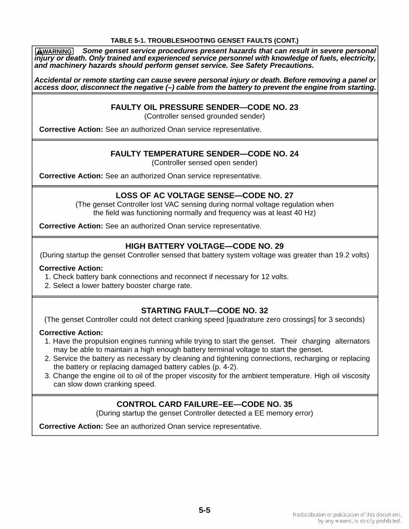
FAULTY OIL PRESSURE SENDER—CODE NO. 23(Controller sensed grounded sender)
Corrective Action: See an authorized Onan service representative.
FAULTY TEMPERATURE SENDER—CODE NO. 24(Controller sensed open sender)
Corrective Action: See an authorized Onan service representative.
LOSS OF AC VOLTAGE SENSE—CODE NO. 27(The genset Controller lost VAC sensing during normal voltage regulation when
the field was functioning normally and frequency was at least 40 Hz)
Corrective Action: See an authorized Onan service representative.
HIGH BATTERY VOLTAGE—CODE NO. 29(During startup the genset Controller sensed that battery system voltage was greater than 19.2 volts)
Corrective Action: 1. Check battery bank connections and reconnect if necessary for 12 volts.2. Select a lower battery booster charge rate.
STARTING FAULT—CODE NO. 32(The genset Controller could not detect cranking speed [quadrature zero crossings] for 3 seconds)
Corrective Action: 1. Have the propulsion engines running while trying to start the genset. Their charging alternators
may be able to maintain a high enough battery terminal voltage to start the genset.2. Service the battery as necessary by cleaning and tightening connections, recharging or replacing
the battery or replacing damaged battery cables (p. 4-2).3. Change the engine oil to oil of the proper viscosity for the ambient temperature. High oil viscosity
can slow down cranking speed.
CONTROL CARD FAILURE–EE—CODE NO. 35(During startup the genset Controller detected a EE memory error)
Corrective Action: See an authorized Onan service representative.
5-6
TABLE 5-1. TROUBLESHOOTING GENSET FAULTS (CONT.)
Some genset service procedures present hazards that can result in severe personalinjury or death. Only trained and experienced service personnel with knowledge of fuels, electricity,and machinery hazards should perform genset service. See Safety Precautions.
Accidental or remote starting can cause severe personal injury or death. Before removing a panel oraccess door, disconnect the negative (–) cable from the battery to prevent the engine from starting.
WARNING
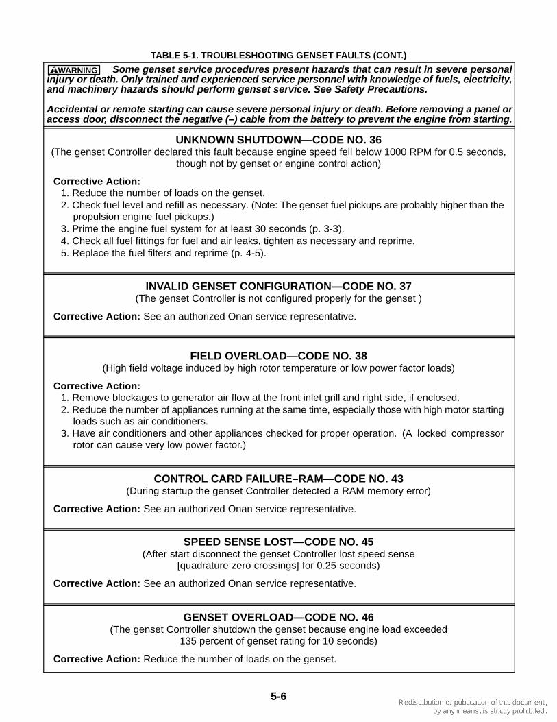
UNKNOWN SHUTDOWN—CODE NO. 36(The genset Controller declared this fault because engine speed fell below 1000 RPM for 0.5 seconds,
though not by genset or engine control action)
Corrective Action: 1. Reduce the number of loads on the genset.2. Check fuel level and refill as necessary. (Note: The genset fuel pickups are probably higher than the
propulsion engine fuel pickups.)3. Prime the engine fuel system for at least 30 seconds (p. 3-3).4. Check all fuel fittings for fuel and air leaks, tighten as necessary and reprime.5. Replace the fuel filters and reprime (p. 4-5).
INVALID GENSET CONFIGURATION—CODE NO. 37(The genset Controller is not configured properly for the genset )
Corrective Action: See an authorized Onan service representative.
FIELD OVERLOAD—CODE NO. 38(High field voltage induced by high rotor temperature or low power factor loads)
Corrective Action: 1. Remove blockages to generator air flow at the front inlet grill and right side, if enclosed.2. Reduce the number of appliances running at the same time, especially those with high motor starting
loads such as air conditioners.3. Have air conditioners and other appliances checked for proper operation. (A locked compressor
rotor can cause very low power factor.)
CONTROL CARD FAILURE–RAM—CODE NO. 43(During startup the genset Controller detected a RAM memory error)
Corrective Action: See an authorized Onan service representative.
SPEED SENSE LOST—CODE NO. 45(After start disconnect the genset Controller lost speed sense
[quadrature zero crossings] for 0.25 seconds)
Corrective Action: See an authorized Onan service representative.
GENSET OVERLOAD—CODE NO. 46(The genset Controller shutdown the genset because engine load exceeded
135 percent of genset rating for 10 seconds)
Corrective Action: Reduce the number of loads on the genset.
5-7
TABLE 5-1. TROUBLESHOOTING GENSET FAULTS (CONT.)
Some genset service procedures present hazards that can result in severe personalinjury or death. Only trained and experienced service personnel with knowledge of fuels, electricity,and machinery hazards should perform genset service. See Safety Precautions.
Accidental or remote starting can cause severe personal injury or death. Before removing a panel oraccess door, disconnect the negative (–) cable from the battery to prevent the engine from starting.
WARNING
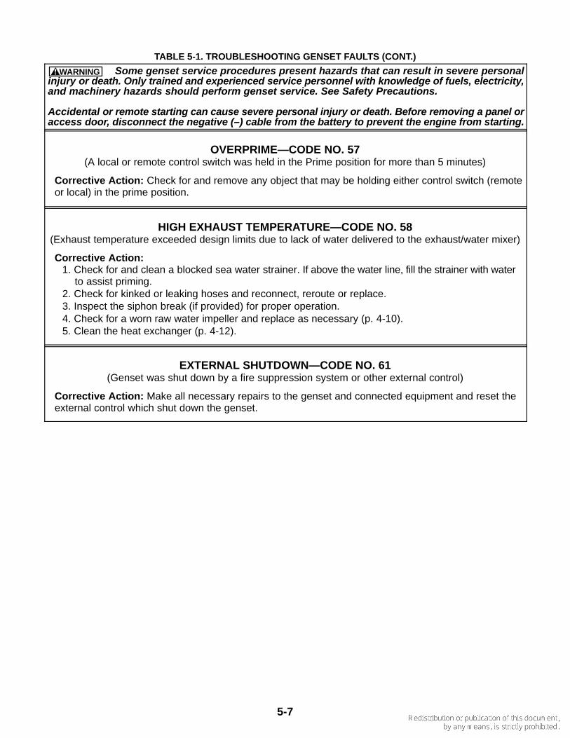
OVERPRIME—CODE NO. 57(A local or remote control switch was held in the Prime position for more than 5 minutes)
Corrective Action: Check for and remove any object that may be holding either control switch (remoteor local) in the prime position.
HIGH EXHAUST TEMPERATURE—CODE NO. 58(Exhaust temperature exceeded design limits due to lack of water delivered to the exhaust/water mixer)
Corrective Action: 1. Check for and clean a blocked sea water strainer. If above the water line, fill the strainer with water
to assist priming.2. Check for kinked or leaking hoses and reconnect, reroute or replace.3. Inspect the siphon break (if provided) for proper operation.4. Check for a worn raw water impeller and replace as necessary (p. 4-10).5. Clean the heat exchanger (p. 4-12).
EXTERNAL SHUTDOWN—CODE NO. 61(Genset was shut down by a fire suppression system or other external control)
Corrective Action: Make all necessary repairs to the genset and connected equipment and reset theexternal control which shut down the genset.

6-1
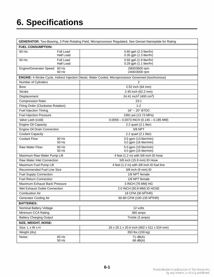
6. Specifications
GENERATOR: Two-Bearing, 2-Pole Rotating Field, Microprocessor Regulated. See Genset Nameplate for Rating
FUEL CONSUMPTION:
60 Hz: Full LoadHalf Load
0.60 gph (2.3 liter/hr)0.35 gph (1.3 liter/hr)
50 Hz: Full LoadHalf Load
0.50 gph (1.9 liter/hr)0.29 gph (1.1 liter/hr)
Engine/Generator Speed: 60 Hz50 Hz
2900/3600 rpm2400/3000 rpm
ENGINE: 4-Stroke Cycle, Indirect Injection Diesel, Water Cooled, Microprocessor Governed (Isochronous)
Number of Cylinders 2
Bore 2.52 inch (64 mm)
Stroke 2.45 inch (62.2 mm)
Displacement 24.41 inch3 (400 cm3)
Compression Ratio 23:1
Firing Order (Clockwise Rotation) 1-2
Fuel Injection Timing 18° – 20° BTDC
Fuel Injection Pressure 1991 psi (13.73 MPa)
Valve Lash (cold) 0.0059 – 0.0073 INCH (0.145 – 0.185 MM)
Engine Oil Capacity 2.2 quart (2.1 liter)
Engine Oil Drain Connection 3/8 NPT
Coolant Capacity 2.2 quart (2.1 liter)
Coolant Flow: 60 Hz50 Hz
3.5 gpm (13 liter/min)3.0 gpm (16 liter/min)
Raw Water Flow: 60 Hz50 Hz
5.0 gpm (19 liter/min)4.0 gpm (15 liter/min)
Maximum Raw Water Pump Lift 4 feet (1.2 m) with 5/8 inch ID hose
Raw Water Inlet Connection 5/8 inch (15.9 mm) ID Hose
Maximum Fuel Pump Lift 4 feet (1.2 m) with 3/8 inch ID fuel line
Recommended Fuel Line Size 3/8 inch (9 mm) ID
Fuel Supply Connection 1/8 NPT female
Fuel Return Connection 1/8 NPT female
Maximum Exhaust Back Pressure 3 INCH (76 MM) HG
Wet Exhaust Outlet Connection 2.0 INCH (50.8 MM) ID HOSE
Combustion Air 18 CFM (30 M3/HR)
Generator Cooling Air 60-80 CFM (100-135 M3/HR)
BATTERIES:
Nominal Battery Voltage 12 volts
Minimum CCA Rating 360 amps
Battery Charging Output Trickle (3 amps)
SIZE, WEIGHT, NOISE:
Size: L x W x H 26 x 20.1 x 20.6 inch (662 x 511 x 524 mm)
Weight (dry) 350 lbs (159 kg)
Noise: 60 Hz50 Hz
71 dB(A)68 dB(A)


7-1
7. Maintenance Record
Record all periodic and unscheduled maintenance and service. See Periodic Maintenance (Sec. 4).
DATEHOURMETER
READINGMAINTENANCE OR SERVICE PERFORMED
Record the name, address, and phone number of your authorized Onan service center.