Embed Size (px)
Citation preview
Last Rev Date: 17 MAY 2016 Page 1 of 27 Fitting instructions# 3789515 Copyright © 2005 by ARB Corporation Limited. All rights reserved, this document must not be reproduced without the express authority of ARB Corporation Ltd
Part Number: 3415220
Product: SUMMIT BULL BAR (suitable for 12000lb winch)
Suited to vehicle/s:
Optional Kits:
TOYOTA LANDCRUISER 200 SERIES 10/2015 ON
VX & Models Only
3500720 Winch Install Kit
3515080 Camera Relocate Kit
3500700 Anti Reflective Tape Kit
If bull bar has been finished with a light colour or highly reflective top
coat, ARB suggest installing 3500700 anti-reflective tape to outer
frames as per instruction 3789301 found in kit.
WARNING REGARDING VEHICLES EQUIPPED WITH LANE DEPARTURE ALERT;
ARB does not recommend installation of antennas/aerials on the front protection bar as it may cause the
lane departure system to malfunction.
REGARDING VEHICLES EQUIPPED WITH SRS AIRBAG;
When installed in accordance with these instructions, the front protection bar does not affect operation of the SRS airbag.
ALSO, NOTE THE FOLLOWING:
This product must be installed exactly as per these instructions using only the hardware supplied.
In the event of damage to any bull bar component, contact your nearest authorised ARB stockist. Repairs or modifications to the impact absorption system must not be attempted.
Do not use this product for any vehicle make or model, other than those specified by ARB.
Do not remove labels from this bull bar.
This product or its fixing must not be modified in any way.
The installation of this product may require the use of specialized tools and/or techniques
It is recommended that this product is only installed by trained personnel
These instructions are correct as at the publication date. ARB Corporation Ltd. cannot be held responsible for the impact of any changes subsequently made by the vehicle manufacturer
During installation, it is the duty of the installer to check correct operation/clearances of all components
Work safely at all times
Unless otherwise instructed, tighten fasteners to specified torque
ARB 4x4 ACCESSORIES
Corporate Head Office
42-44 Garden St Tel: +61 (3) 9761 6622 Kilsyth, Victoria Fax: +61 (3) 9761 6807 AUSTRALIA 3137
Australian enquiries [email protected] North & South American enquiries [email protected] Other international enquiries [email protected]
www.arb.com.au
Last Rev Date: 17 MAY 2016 Page 2 of 27 Fitting instructions# 3789515 Copyright © 2005 by ARB Corporation Limited. All rights reserved, this document must not be reproduced without the express authority of ARB Corporation Ltd
GENERAL CARE AND MAINTENANCE By choosing an ARB Bar, you have bought a product that is one of the most sought after 4WD products
in the world. Your bar is a properly engineered, reliable, quality accessory that represents excellent value. To keep your bar in original condition it is important to care and maintain it following these recommendations: Prior to exposure to the weather your bar should be treated to a Carnauba based polish on all
exposed surfaces. It is recommended that this is performed on a six monthly basis or following exposure to salt, mud, sand or other contaminants.
As part of any Pre Trip Preparation, or on an annual basis, it is recommended that a thorough visual inspection of the bar is carried out, making sure that all bolts and other components are torqued to the correct specification. Also check that all wiring sheaths, connectors, and fittings are free of damage. Replace any components as necessary. This service can be performed by your local authorized ARB Stockist.
FITTING REQUIREMENTS
REQUIRED TOOLS FOR FITMENT OF PRODUCT:
Metric socket and spanner sets 8-25mm range External Circlip pliers
Screwdrivers, Philips and Flat blade Power Jigsaw with blade for plastic cutting
Short Body Power Drill 13mm (1/2”) capacity Dia 7.0mm (5/16”) and 10.5mm (25/64”) drill bits
Torque Wrench (9-102Nm) Marking pen
Brake line clamp Soft Hammer
Metric hex&torx key set Loctite© 262 or equiv.
Wide masking tape Stanley knife and Multitool
Small Spirit Level Tape Measure & 2 x 300mm rulers
Right-angled Drill Paint black fast drying
HAVE AVAILABLE THESE SAFETY ITEMS WHEN FITTING PRODUCT:
Protective eyewear
Hearing protection
NOTE: ‘WARNING’ notes in the fitting procedure relate to OHS situations, where to avoid a
potentially hazardous situation it is suggested that protective safety gear be worn or a safe work
procedure be employed. If these notes and warnings are not heeded, injury may result.
FASTENER TORQUE SETTINGS:
SIZE Torque Nm Torque lbft
M6 9Nm 7lbft
M8 22Nm 16lbft
M10 44Nm 32lbft
M12 77Nm 57lbft
Last Rev Date: 17 MAY 2016 Page 3 of 27 Fitting instructions# 3789515 Copyright © 2005 by ARB Corporation Limited. All rights reserved, this document must not be reproduced without the express authority of ARB Corporation Ltd
PARTS LISTING
APPLICATION. PART NO. QTY DESCRIPTION
Mount Brackets To Chassis
3757602R 3757602L 6151428 6151429 6151435 5846400
1 1 2 2 2 2
Bracket Mount RHS Bracket Mount LHS Flange Nut M12 x 1.75 Chassis Stud M12 x 265 x 1.75 Nut Clevis Packer M12 x 8mm
Brace Assembly
4681274 6151357 6151321
1 7 7
Brace SEMS Bolt M10 x 1.5 x 30mm Nut Flanged M10 x 1.5
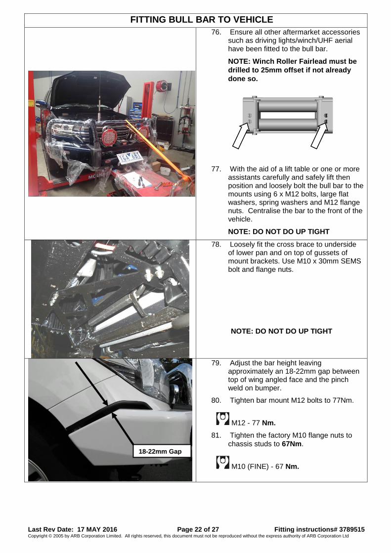
Bull Bar To Mount Bracket Assy
6151357 6151321 6151360 6151428 4581049 4581064
4 4 6 6 6 6
SEMS Bolt M10 x 1.5 x 30mm Nut Flanged M10 x 1.5 Bolt M12 x 1.75 x 35mm Flange Nut M12 x 1.75 Washer Flat M12 Washer Spring M12 tzp480
Stone Tray to Bull Bar
6522683 6151300 6151711 4581082 4581287 6151270 4721518
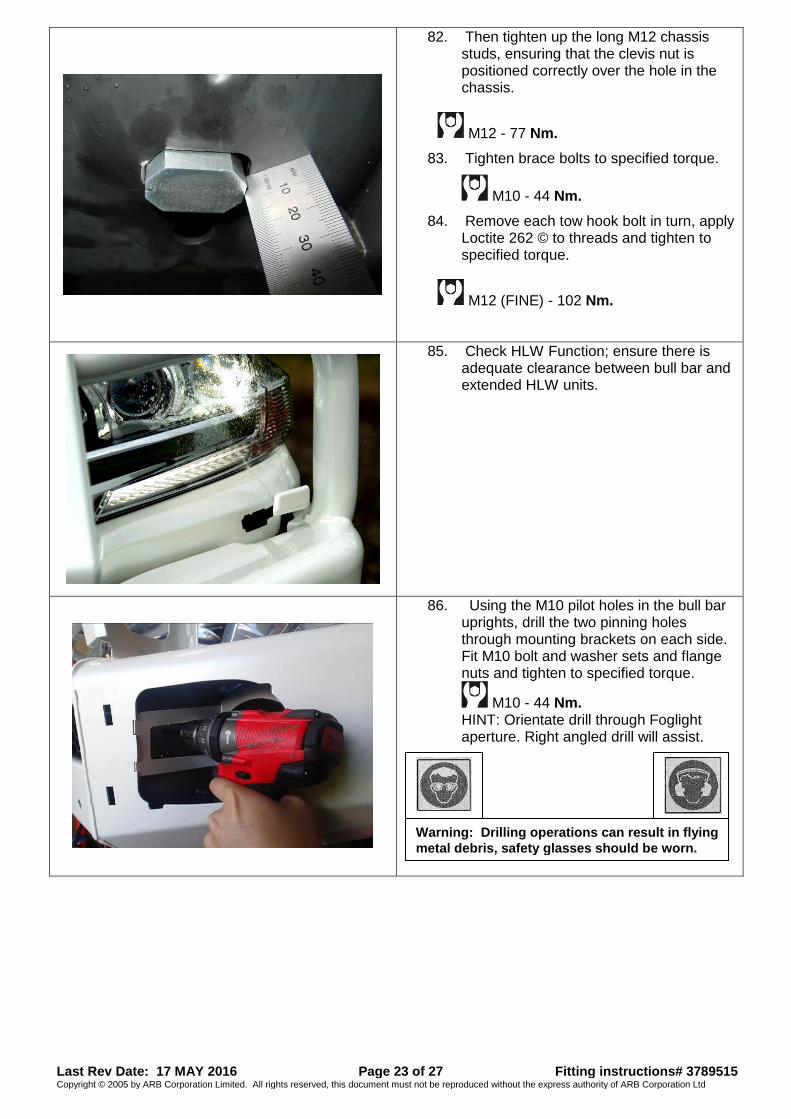
1 4 4 6 6 2 2
Stone Tray Nut Cage M6 Screw BTN HD TX M6 x 25 BTZP480 Washer Flat M6 x 16 x 3 Washer Spring M6 Bolt M6 x 40 Spacer Tube 18mm
Fit Lights and Mouldings
3500710 5100200 5100210 6821287 3163156 6821116 3500680 3759896
3759897R 3759897L 6151459 6151223
1 1 1 1 1 4 1 2 1 1 16 16
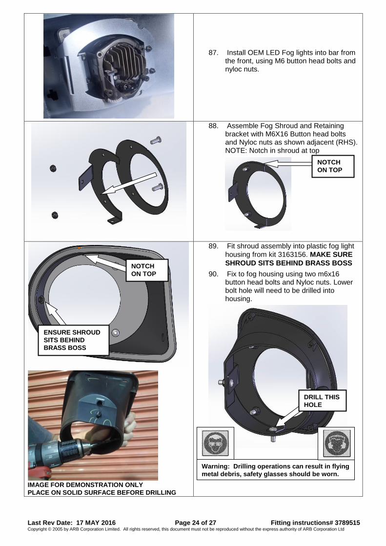
Grille Split Pan Kit Buff Kit 2pce Front Section Kit Buff Kit 2pce Rear Upright Bar Kit Lamp Led Indicator Clearance Kit Surround ARB Foglight Kit Reduced Grommet Nylon Snap In Type Fog Lamp Housing Clear Lens Kit Bracket LC200 FOG Shroud Bracket Shroud Retainer R Bracket Shroud Retainer R Screw BTN HD m6 x16 BZ Nut Nyloc M6 x 1.0 BZ
Number Plate To Bull Bar
6821189 6151384 6151213 3759488 4581287 4584295 6151128
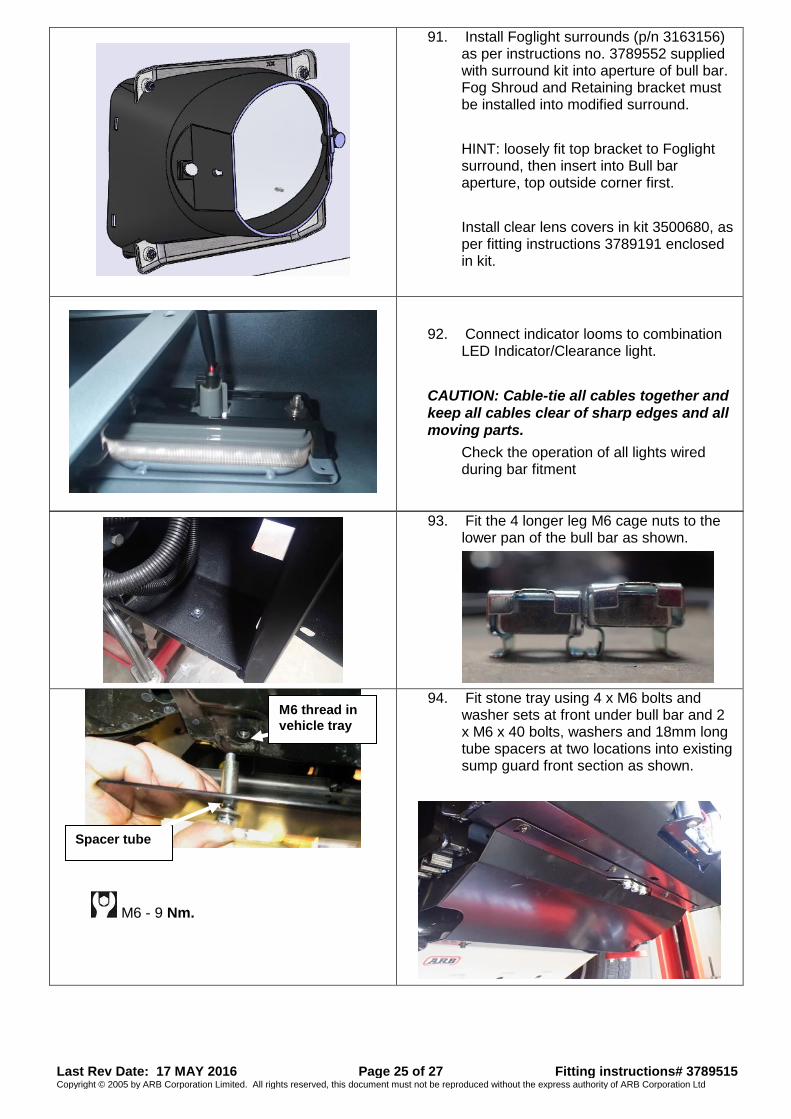
2 2 3 1 3 3 3
Grommet round Screw self tapping pan head Bolt M6 x 1.0 x 20mm Gd 8.8 Bz Bracket Lic Plate Fixed Large Rad Washer Spring M6 x 2.5 x 1.6 Bz Washer Flat M6 x 12 x 1.3 Bz Nut Flange M6 x 1.0 ZP
Wing Inner Panels
6523075R 6523075L 6151315 6151711 4581082 4581287 3759754 6151546 4581075 4581047 6151132
1 1 10 10 10 10 2 4 4 4 4
Panel Wing LC200 RH Panel Wing LC200 LH Nut Caged M6 Screw BTN HD TX M6 x 25 BTZP480 Washer Flat M6 Blk Washer Spring M6 Blk
Brkt Wing Panel LC200 Bolt M8x1.25x20 Washer Flat M8 Washer Spring M8 Nut M8 Flanged
Fit Winch Cover Panel
6522985 6151213 4581287 4584295 6151128
1 4 4 4 4
Panel Press Form Cover LC200 Bolt M6 x 1.0 x 20 Gd8.8 BZ Washer Spring M6 x 2.5 x 1.6 BLK ZN Washer Flat M6 X 13 X 1.6 BLK ZN Nut Flange M6 x 1.0 ZP
Miscellaneous
6191030 3789519 180302
2 1 6
Trim Pinch Weld 520mm Template Bumper Cutting Cable ties
Last Rev Date: 17 MAY 2016 Page 4 of 27 Fitting instructions# 3789515 Copyright © 2005 by ARB Corporation Limited. All rights reserved, this document must not be reproduced without the express authority of ARB Corporation Ltd
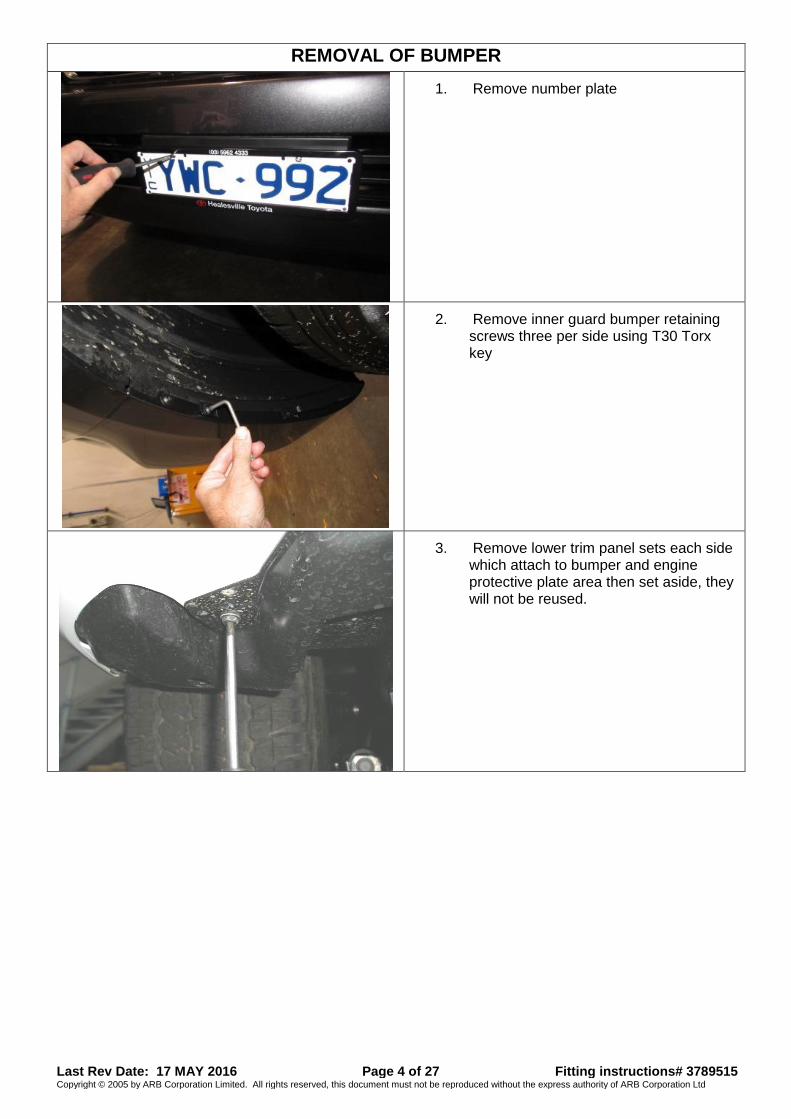
REMOVAL OF BUMPER
1. Remove number plate
2. Remove inner guard bumper retaining screws three per side using T30 Torx key
3. Remove lower trim panel sets each side which attach to bumper and engine protective plate area then set aside, they will not be reused.
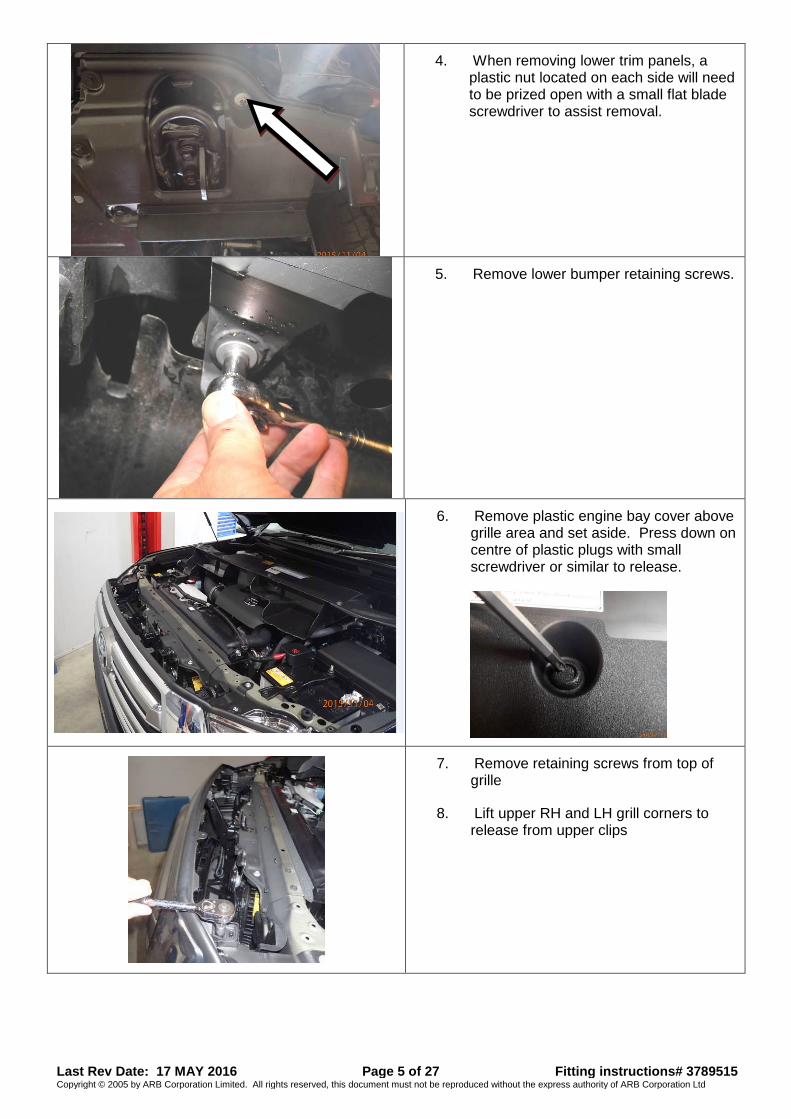
Last Rev Date: 17 MAY 2016 Page 5 of 27 Fitting instructions# 3789515 Copyright © 2005 by ARB Corporation Limited. All rights reserved, this document must not be reproduced without the express authority of ARB Corporation Ltd
4. When removing lower trim panels, a plastic nut located on each side will need to be prized open with a small flat blade screwdriver to assist removal.
5. Remove lower bumper retaining screws.
6. Remove plastic engine bay cover above grille area and set aside. Press down on centre of plastic plugs with small screwdriver or similar to release.
7. Remove retaining screws from top of grille
8. Lift upper RH and LH grill corners to release from upper clips
Last Rev Date: 17 MAY 2016 Page 6 of 27 Fitting instructions# 3789515 Copyright © 2005 by ARB Corporation Limited. All rights reserved, this document must not be reproduced without the express authority of ARB Corporation Ltd
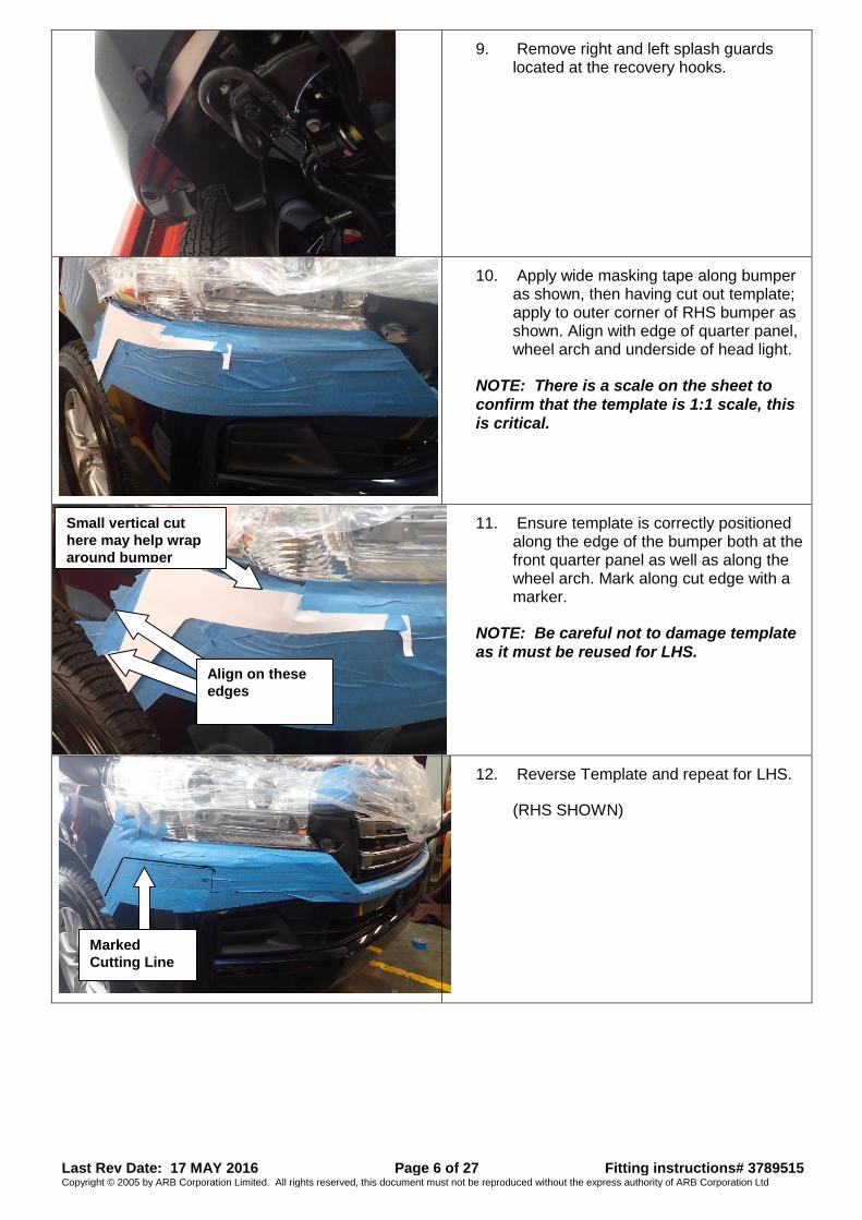
9. Remove right and left splash guards located at the recovery hooks.
10. Apply wide masking tape along bumper as shown, then having cut out template; apply to outer corner of RHS bumper as shown. Align with edge of quarter panel, wheel arch and underside of head light.
NOTE: There is a scale on the sheet to
confirm that the template is 1:1 scale, this
is critical.
11. Ensure template is correctly positioned along the edge of the bumper both at the front quarter panel as well as along the wheel arch. Mark along cut edge with a marker.
NOTE: Be careful not to damage template
as it must be reused for LHS.
12. Reverse Template and repeat for LHS.
(RHS SHOWN)
Align on these
edges
Small vertical cut
here may help wrap
around bumper
Marked
Cutting Line
Last Rev Date: 17 MAY 2016 Page 7 of 27 Fitting instructions# 3789515 Copyright © 2005 by ARB Corporation Limited. All rights reserved, this document must not be reproduced without the express authority of ARB Corporation Ltd
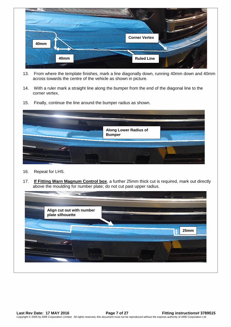
13. From where the template finishes, mark a line diagonally down, running 40mm down and 40mm across towards the centre of the vehicle as shown in picture.
14. With a ruler mark a straight line along the bumper from the end of the diagonal line to the corner vertex.
15. Finally, continue the line around the bumper radius as shown.
16. Repeat for LHS.
17. If Fitting Warn Magnum Control box, a further 25mm thick cut is required, mark out directly above the moulding for number plate; do not cut past upper radius.
Along Lower Radius of
Bumper
25mm
Align cut out with number
plate silhouette
40mm
40mm
Corner Vertex
Ruled Line
Last Rev Date: 17 MAY 2016 Page 8 of 27 Fitting instructions# 3789515 Copyright © 2005 by ARB Corporation Limited. All rights reserved, this document must not be reproduced without the express authority of ARB Corporation Ltd
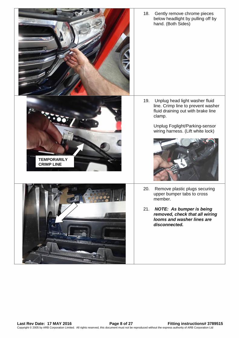
18. Gently remove chrome pieces below headlight by pulling off by hand. (Both Sides)
19. Unplug head light washer fluid line. Crimp line to prevent washer fluid draining out with brake line clamp.
Unplug Foglight/Parking-sensor wiring harness. (Lift white lock)
20. Remove plastic plugs securing upper bumper tabs to cross member.
21. NOTE: As bumper is being
removed, check that all wiring
looms and washer lines are
disconnected.
TEMPORARILY
CRIMP LINE
Last Rev Date: 17 MAY 2016 Page 9 of 27 Fitting instructions# 3789515 Copyright © 2005 by ARB Corporation Limited. All rights reserved, this document must not be reproduced without the express authority of ARB Corporation Ltd
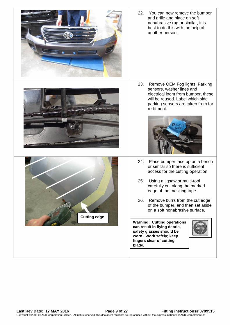
22. You can now remove the bumper and grille and place on soft nonabrasive rug or similar, it is best to do this with the help of another person.
23. Remove OEM Fog lights, Parking sensors, washer lines and electrical loom from bumper, these will be reused. Label which side parking sensors are taken from for re-fitment.
24. Place bumper face up on a bench or similar so there is sufficient access for the cutting operation
25. Using a jigsaw or multi-tool carefully cut along the marked edge of the masking tape.
26. Remove burrs from the cut edge of the bumper, and then set aside on a soft nonabrasive surface.
Cutting edge
Warning: Cutting operations
can result in flying debris,
safety glasses should be
worn. Work safely; keep
fingers clear of cutting
blade.
Last Rev Date: 17 MAY 2016 Page 10 of 27 Fitting instructions# 3789515 Copyright © 2005 by ARB Corporation Limited. All rights reserved, this document must not be reproduced without the express authority of ARB Corporation Ltd
27. Remove foam absorber bar and set aside, this will not be reused
28. Remove crash beam with mount brackets and set aside, retain only M10 flange nuts for reuse.
29. Remove tow hooks and set aside, these will be reused.
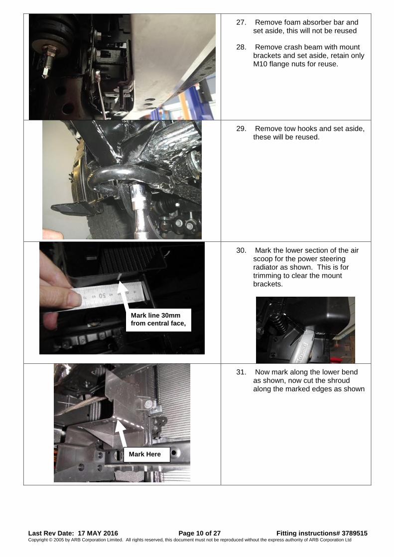
30. Mark the lower section of the air scoop for the power steering radiator as shown. This is for trimming to clear the mount brackets.
31. Now mark along the lower bend as shown, now cut the shroud along the marked edges as shown
Mark Here
Mark line 30mm
from central face,
Last Rev Date: 17 MAY 2016 Page 11 of 27 Fitting instructions# 3789515 Copyright © 2005 by ARB Corporation Limited. All rights reserved, this document must not be reproduced without the express authority of ARB Corporation Ltd
32. Once the cut is complete it should look as displayed.
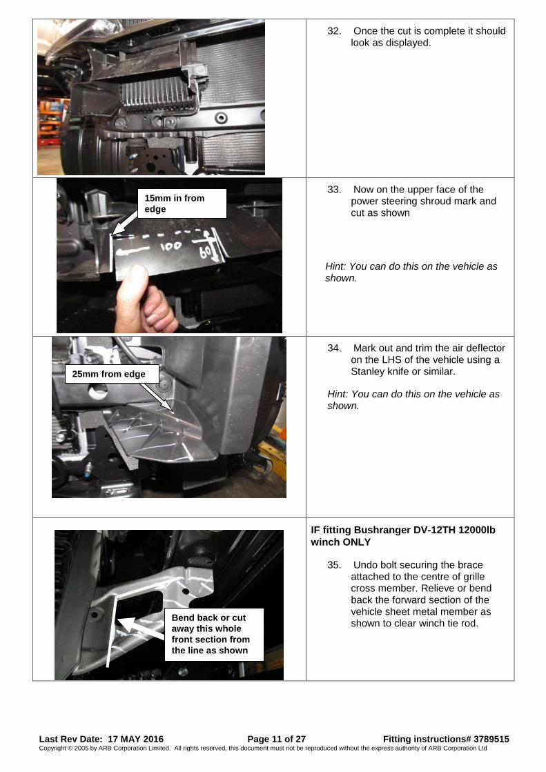
33. Now on the upper face of the power steering shroud mark and cut as shown
Hint: You can do this on the vehicle as shown.
34. Mark out and trim the air deflector on the LHS of the vehicle using a Stanley knife or similar.
Hint: You can do this on the vehicle as shown.
IF fitting Bushranger DV-12TH 12000lb
winch ONLY
35. Undo bolt securing the brace attached to the centre of grille cross member. Relieve or bend back the forward section of the vehicle sheet metal member as shown to clear winch tie rod.
Bend back or cut
away this whole
front section from
the line as shown
15mm in from
edge
25mm from edge
Last Rev Date: 17 MAY 2016 Page 12 of 27 Fitting instructions# 3789515 Copyright © 2005 by ARB Corporation Limited. All rights reserved, this document must not be reproduced without the express authority of ARB Corporation Ltd
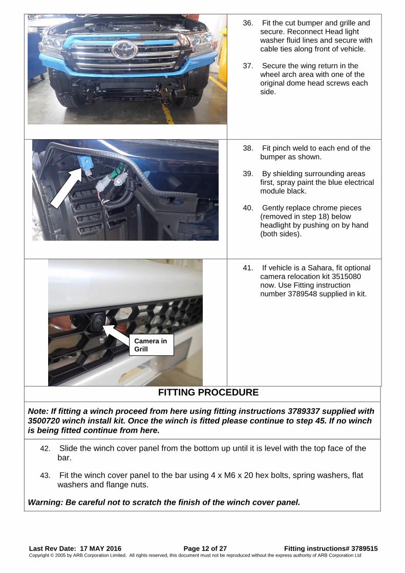
36. Fit the cut bumper and grille and secure. Reconnect Head light washer fluid lines and secure with cable ties along front of vehicle.
37. Secure the wing return in the wheel arch area with one of the original dome head screws each side.
38. Fit pinch weld to each end of the bumper as shown.
39. By shielding surrounding areas first, spray paint the blue electrical module black.
40. Gently replace chrome pieces (removed in step 18) below headlight by pushing on by hand (both sides).
41. If vehicle is a Sahara, fit optional camera relocation kit 3515080 now. Use Fitting instruction number 3789548 supplied in kit.
FITTING PROCEDURE
Note: If fitting a winch proceed from here using fitting instructions 3789337 supplied with
3500720 winch install kit. Once the winch is fitted please continue to step 45. If no winch is being fitted continue from here.
42. Slide the winch cover panel from the bottom up until it is level with the top face of the bar.
43. Fit the winch cover panel to the bar using 4 x M6 x 20 hex bolts, spring washers, flat washers and flange nuts.
Warning: Be careful not to scratch the finish of the winch cover panel.
Camera in
Grill
Last Rev Date: 17 MAY 2016 Page 13 of 27 Fitting instructions# 3789515 Copyright © 2005 by ARB Corporation Limited. All rights reserved, this document must not be reproduced without the express authority of ARB Corporation Ltd
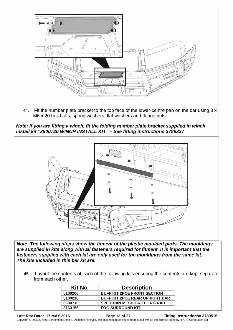
44. Fit the number plate bracket to the top face of the lower-centre pan on the bar using 3 x M6 x 20 hex bolts, spring washers, flat washers and flange nuts.
Note: If you are fitting a winch, fit the folding number plate bracket supplied in winch install kit “3500720 WINCH INSTALL KIT” – See fitting instructions 3789337
Note: The following steps show the fitment of the plastic moulded parts. The mouldings are supplied in kits along with all fasteners required for fitment. It is important that the fasteners supplied with each kit are only used for the mouldings from the same kit. The kits included in this bar kit are:
45. Layout the contents of each of the following kits ensuring the contents are kept separate from each other.
Kit No. Description 5100200 BUFF KIT 2PCE FRONT SECTION 5100210 BUFF KIT 2PCE REAR UPRIGHT BAR 3500710 SPLIT PAN MESH GRILL LRG RAD 3163156 FOG SURROUND KIT
Last Rev Date: 17 MAY 2016 Page 14 of 27 Fitting instructions# 3789515 Copyright © 2005 by ARB Corporation Limited. All rights reserved, this document must not be reproduced without the express authority of ARB Corporation Ltd
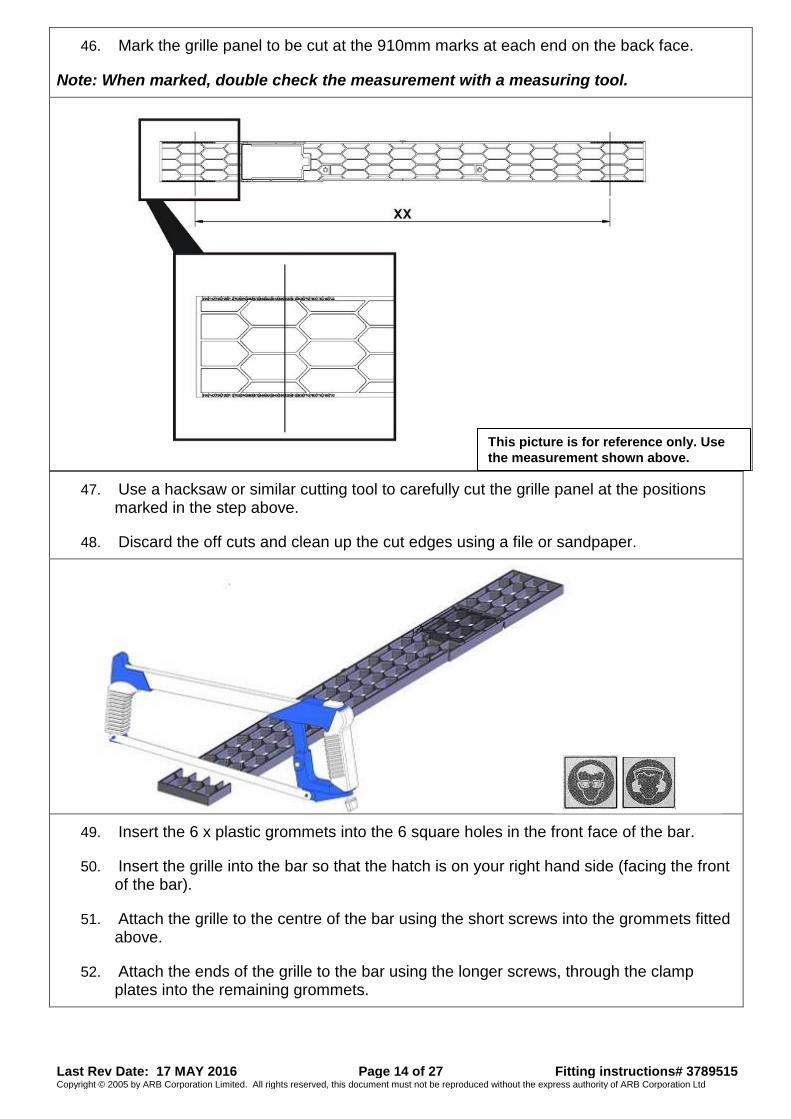
46. Mark the grille panel to be cut at the 910mm marks at each end on the back face.
Note: When marked, double check the measurement with a measuring tool.
47. Use a hacksaw or similar cutting tool to carefully cut the grille panel at the positions marked in the step above.
48. Discard the off cuts and clean up the cut edges using a file or sandpaper.
49. Insert the 6 x plastic grommets into the 6 square holes in the front face of the bar.
50. Insert the grille into the bar so that the hatch is on your right hand side (facing the front of the bar).
51. Attach the grille to the centre of the bar using the short screws into the grommets fitted above.
52. Attach the ends of the grille to the bar using the longer screws, through the clamp plates into the remaining grommets.
This picture is for reference only. Use
the measurement shown above.
Last Rev Date: 17 MAY 2016 Page 15 of 27 Fitting instructions# 3789515 Copyright © 2005 by ARB Corporation Limited. All rights reserved, this document must not be reproduced without the express authority of ARB Corporation Ltd
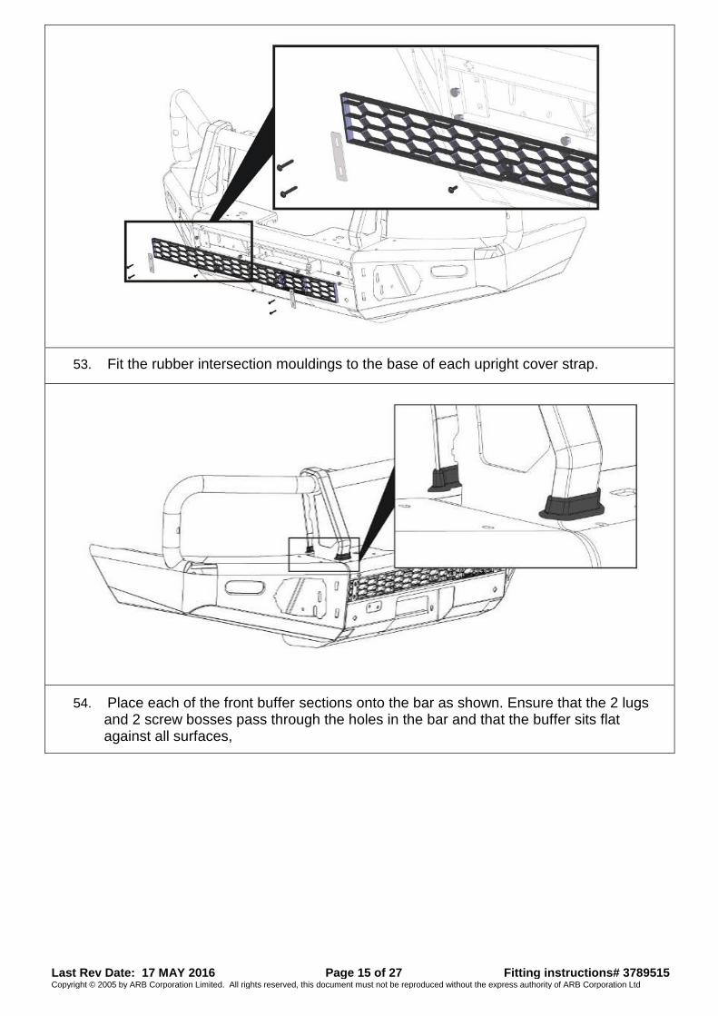
53. Fit the rubber intersection mouldings to the base of each upright cover strap.
54. Place each of the front buffer sections onto the bar as shown. Ensure that the 2 lugs and 2 screw bosses pass through the holes in the bar and that the buffer sits flat against all surfaces,
Last Rev Date: 17 MAY 2016 Page 16 of 27 Fitting instructions# 3789515 Copyright © 2005 by ARB Corporation Limited. All rights reserved, this document must not be reproduced without the express authority of ARB Corporation Ltd
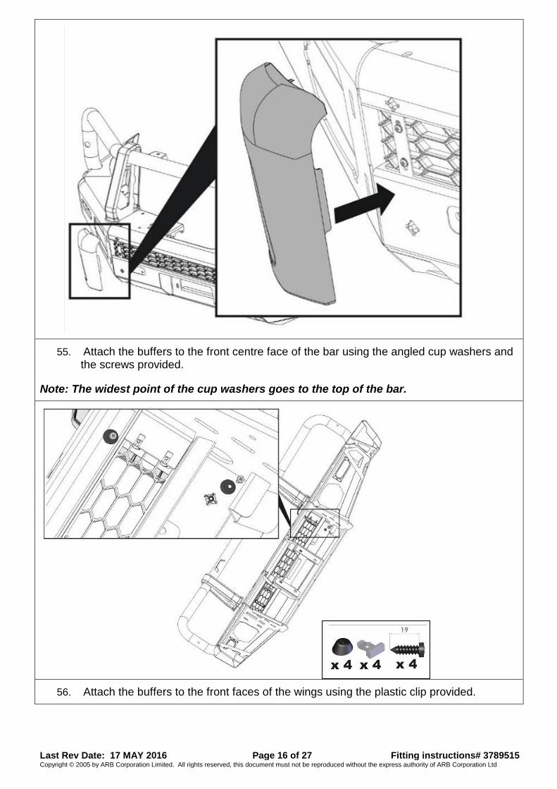
55. Attach the buffers to the front centre face of the bar using the angled cup washers and the screws provided.
Note: The widest point of the cup washers goes to the top of the bar.
56. Attach the buffers to the front faces of the wings using the plastic clip provided.
Last Rev Date: 17 MAY 2016 Page 17 of 27 Fitting instructions# 3789515 Copyright © 2005 by ARB Corporation Limited. All rights reserved, this document must not be reproduced without the express authority of ARB Corporation Ltd
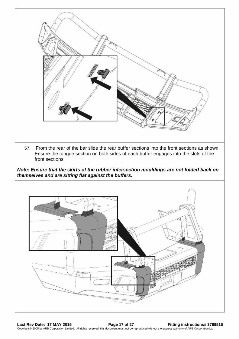
57. From the rear of the bar slide the rear buffer sections into the front sections as shown. Ensure the tongue section on both sides of each buffer engages into the slots of the front sections.
Note: Ensure that the skirts of the rubber intersection mouldings are not folded back on themselves and are sitting flat against the buffers.
Last Rev Date: 17 MAY 2016 Page 18 of 27 Fitting instructions# 3789515 Copyright © 2005 by ARB Corporation Limited. All rights reserved, this document must not be reproduced without the express authority of ARB Corporation Ltd
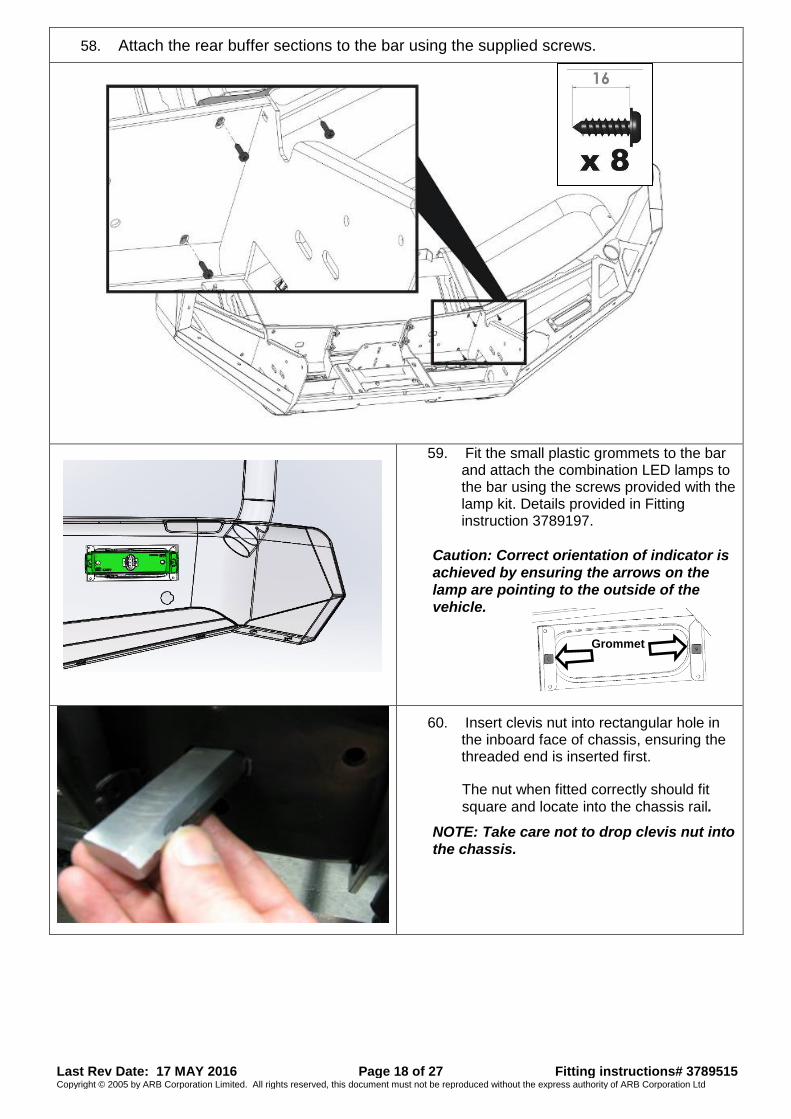
58. Attach the rear buffer sections to the bar using the supplied screws.
59. Fit the small plastic grommets to the bar and attach the combination LED lamps to the bar using the screws provided with the lamp kit. Details provided in Fitting instruction 3789197.
Caution: Correct orientation of indicator is
achieved by ensuring the arrows on the
lamp are pointing to the outside of the
vehicle.
60. Insert clevis nut into rectangular hole in the inboard face of chassis, ensuring the threaded end is inserted first.
The nut when fitted correctly should fit
square and locate into the chassis rail.
NOTE: Take care not to drop clevis nut into
the chassis.
Grommet
Last Rev Date: 17 MAY 2016 Page 19 of 27 Fitting instructions# 3789515 Copyright © 2005 by ARB Corporation Limited. All rights reserved, this document must not be reproduced without the express authority of ARB Corporation Ltd
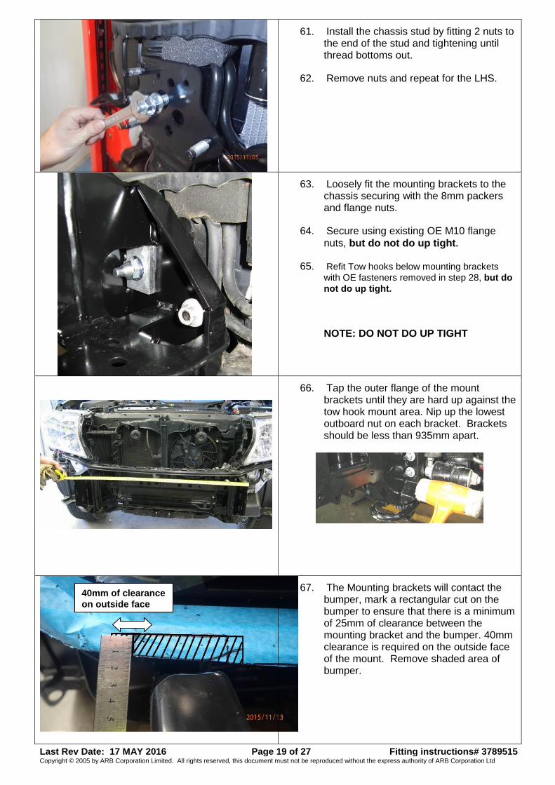
61. Install the chassis stud by fitting 2 nuts to the end of the stud and tightening until thread bottoms out.
62. Remove nuts and repeat for the LHS.
63. Loosely fit the mounting brackets to the chassis securing with the 8mm packers and flange nuts.
64. Secure using existing OE M10 flange
nuts, but do not do up tight.
65. Refit Tow hooks below mounting brackets
with OE fasteners removed in step 28, but do
not do up tight.
NOTE: DO NOT DO UP TIGHT
66. Tap the outer flange of the mount brackets until they are hard up against the tow hook mount area. Nip up the lowest outboard nut on each bracket. Brackets should be less than 935mm apart.
67. The Mounting brackets will contact the bumper, mark a rectangular cut on the bumper to ensure that there is a minimum of 25mm of clearance between the mounting bracket and the bumper. 40mm clearance is required on the outside face of the mount. Remove shaded area of bumper.
40mm of clearance
on outside face
Last Rev Date: 17 MAY 2016 Page 20 of 27 Fitting instructions# 3789515 Copyright © 2005 by ARB Corporation Limited. All rights reserved, this document must not be reproduced without the express authority of ARB Corporation Ltd
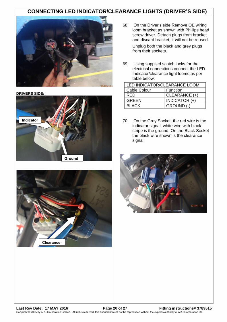
CONNECTING LED INDICATOR/CLEARANCE LIGHTS (DRIVER’S SIDE)
DRIVERS SIDE:
68. On the Driver’s side Remove OE wiring loom bracket as shown with Phillips head screw driver. Detach plugs from bracket and discard bracket, it will not be reused.
Unplug both the black and grey plugs from their sockets.
69. Using supplied scotch locks for the electrical connections connect the LED Indicator/clearance light looms as per table below:
LED INDICATOR/CLEARANCE LOOM
Cable Colour Function
RED CLEARANCE (+)
GREEN INDICATOR (+)
BLACK GROUND (-)
70. On the Grey Socket, the red wire is the indicator signal; white wire with black stripe is the ground. On the Black Socket the black wire shown is the clearance signal.
Ground
Indicator
Clearance

Last Rev Date: 17 MAY 2016 Page 21 of 27 Fitting instructions# 3789515 Copyright © 2005 by ARB Corporation Limited. All rights reserved, this document must not be reproduced without the express authority of ARB Corporation Ltd
CONNECTING LED INDICATOR/CLEARANCE (PASSENGER SIDE)
71. As done on Drivers Side, remove and discard OE loom bracket. Split grey plug and socket as shown adjacent.
72. Using supplied scotch locks, connect LED light loom as per table in step 69. Blue wire shown is the indicator signal; white wire with black stripe is the ground. On the black socket, the black wire shown is the clearance signal.
73. Once satisfied that sturdy electrical connections have been made on both sides, cable tie both harnesses back onto the sheet metal underneath the headlights as shown.
If installing driving lights, the high beam signal can be tapped into on the passenger side of the vehicle using the black wire on the black plug shown.
74. Fit both parking sensors into aperture in wings. Plug must be pointing outboard. Unwrap electrical tape from OEM loom in order to split sensor plug from Foglight plug for greater reach.
75. Reconnect FOG/SENSOR loom to
vehicle and fasten with cable ties along front of vehicle.
Clearance
Indicator
Ground
Painted in
Step# 39
Last Rev Date: 17 MAY 2016 Page 22 of 27 Fitting instructions# 3789515 Copyright © 2005 by ARB Corporation Limited. All rights reserved, this document must not be reproduced without the express authority of ARB Corporation Ltd
FITTING BULL BAR TO VEHICLE
76. Ensure all other aftermarket accessories such as driving lights/winch/UHF aerial have been fitted to the bull bar.
NOTE: Winch Roller Fairlead must be
drilled to 25mm offset if not already
done so.
77. With the aid of a lift table or one or more assistants carefully and safely lift then position and loosely bolt the bull bar to the mounts using 6 x M12 bolts, large flat washers, spring washers and M12 flange nuts. Centralise the bar to the front of the vehicle.
NOTE: DO NOT DO UP TIGHT
78. Loosely fit the cross brace to underside of lower pan and on top of gussets of mount brackets. Use M10 x 30mm SEMS bolt and flange nuts.
NOTE: DO NOT DO UP TIGHT
79. Adjust the bar height leaving approximately an 18-22mm gap between top of wing angled face and the pinch weld on bumper.
80. Tighten bar mount M12 bolts to 77Nm.
M12 - 77 Nm.
81. Tighten the factory M10 flange nuts to
chassis studs to 67Nm.
M10 (FINE) - 67 Nm.
18-22mm Gap
Last Rev Date: 17 MAY 2016 Page 23 of 27 Fitting instructions# 3789515 Copyright © 2005 by ARB Corporation Limited. All rights reserved, this document must not be reproduced without the express authority of ARB Corporation Ltd
82. Then tighten up the long M12 chassis studs, ensuring that the clevis nut is positioned correctly over the hole in the chassis.
M12 - 77 Nm.
83. Tighten brace bolts to specified torque.
M10 - 44 Nm.
84. Remove each tow hook bolt in turn, apply Loctite 262 © to threads and tighten to specified torque.
M12 (FINE) - 102 Nm.
85. Check HLW Function; ensure there is adequate clearance between bull bar and extended HLW units.
86. Using the M10 pilot holes in the bull bar uprights, drill the two pinning holes through mounting brackets on each side. Fit M10 bolt and washer sets and flange nuts and tighten to specified torque.
M10 - 44 Nm. HINT: Orientate drill through Foglight aperture. Right angled drill will assist.
Warning: Drilling operations can result in flying
metal debris, safety glasses should be worn.
Last Rev Date: 17 MAY 2016 Page 24 of 27 Fitting instructions# 3789515 Copyright © 2005 by ARB Corporation Limited. All rights reserved, this document must not be reproduced without the express authority of ARB Corporation Ltd
87. Install OEM LED Fog lights into bar from the front, using M6 button head bolts and nyloc nuts.
88. Assemble Fog Shroud and Retaining bracket with M6X16 Button head bolts and Nyloc nuts as shown adjacent (RHS). NOTE: Notch in shroud at top
IMAGE FOR DEMONSTRATION ONLY
PLACE ON SOLID SURFACE BEFORE DRILLING
89. Fit shroud assembly into plastic fog light
housing from kit 3163156. MAKE SURE
SHROUD SITS BEHIND BRASS BOSS
90. Fix to fog housing using two m6x16 button head bolts and Nyloc nuts. Lower bolt hole will need to be drilled into housing.
NOTCH
ON TOP
ENSURE SHROUD
SITS BEHIND
BRASS BOSS
NOTCH
ON TOP
Warning: Drilling operations can result in flying
metal debris, safety glasses should be worn.
DRILL THIS
HOLE
Last Rev Date: 17 MAY 2016 Page 25 of 27 Fitting instructions# 3789515 Copyright © 2005 by ARB Corporation Limited. All rights reserved, this document must not be reproduced without the express authority of ARB Corporation Ltd
91. Install Foglight surrounds (p/n 3163156) as per instructions no. 3789552 supplied with surround kit into aperture of bull bar. Fog Shroud and Retaining bracket must be installed into modified surround.
HINT: loosely fit top bracket to Foglight surround, then insert into Bull bar aperture, top outside corner first.
Install clear lens covers in kit 3500680, as per fitting instructions 3789191 enclosed in kit.
92. Connect indicator looms to combination LED Indicator/Clearance light.
CAUTION: Cable-tie all cables together and
keep all cables clear of sharp edges and all
moving parts.
Check the operation of all lights wired during bar fitment
93. Fit the 4 longer leg M6 cage nuts to the lower pan of the bull bar as shown.
M6 - 9 Nm.
94. Fit stone tray using 4 x M6 bolts and washer sets at front under bull bar and 2 x M6 x 40 bolts, washers and 18mm long tube spacers at two locations into existing sump guard front section as shown.
Spacer tube
M6 thread in
vehicle tray
Last Rev Date: 17 MAY 2016 Page 26 of 27 Fitting instructions# 3789515 Copyright © 2005 by ARB Corporation Limited. All rights reserved, this document must not be reproduced without the express authority of ARB Corporation Ltd
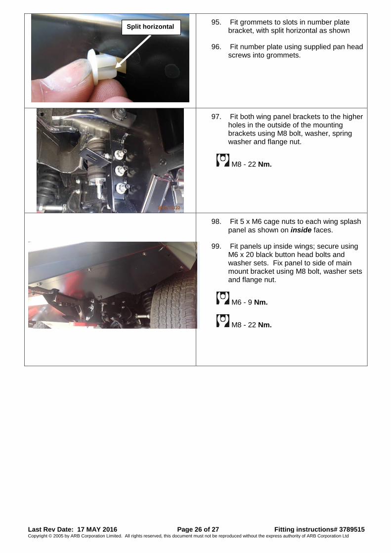
95. Fit grommets to slots in number plate bracket, with split horizontal as shown
96. Fit number plate using supplied pan head screws into grommets.
97. Fit both wing panel brackets to the higher holes in the outside of the mounting brackets using M8 bolt, washer, spring washer and flange nut.
M8 - 22 Nm.
98. Fit 5 x M6 cage nuts to each wing splash
panel as shown on inside faces.
99. Fit panels up inside wings; secure using M6 x 20 black button head bolts and washer sets. Fix panel to side of main mount bracket using M8 bolt, washer sets and flange nut.
M6 - 9 Nm.
M8 - 22 Nm.
Split horizontal
Last Rev Date: 17 MAY 2016 Page 27 of 27 Fitting instructions# 3789515 Copyright © 2005 by ARB Corporation Limited. All rights reserved, this document must not be reproduced without the express authority of ARB Corporation Ltd
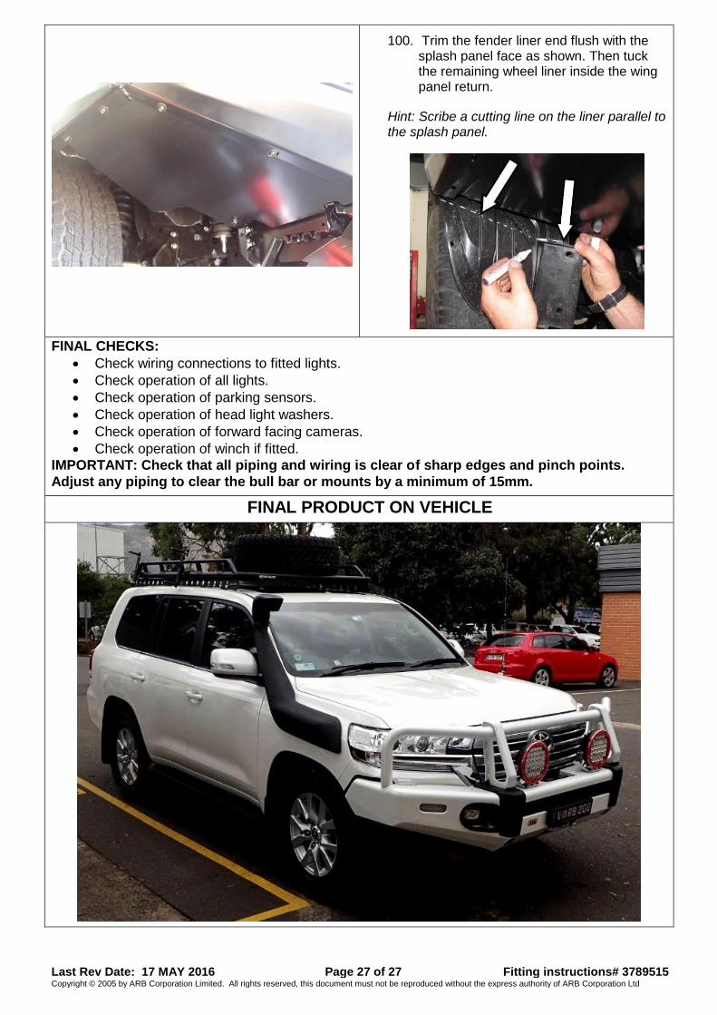
100. Trim the fender liner end flush with the splash panel face as shown. Then tuck the remaining wheel liner inside the wing panel return.
Hint: Scribe a cutting line on the liner parallel to the splash panel.
FINAL CHECKS:
Check wiring connections to fitted lights.
Check operation of all lights.
Check operation of parking sensors.
Check operation of head light washers.
Check operation of forward facing cameras.
Check operation of winch if fitted.
IMPORTANT: Check that all piping and wiring is clear of sharp edges and pinch points.
Adjust any piping to clear the bull bar or mounts by a minimum of 15mm.
FINAL PRODUCT ON VEHICLE