Embed Size (px)
Citation preview

ChemicalScience
EDGE ARTICLE
Ope
n A
cces
s A
rtic
le. P
ublis
hed
on 2
3 M
arch
201
7. D
ownl
oade
d on
12/
22/2
021
9:09
:33
AM
. T
his
artic
le is
lice
nsed
und
er a
Cre
ativ
e C
omm
ons
Attr
ibut
ion-
Non
Com
mer
cial
3.0
Unp
orte
d L
icen
ce.
View Article OnlineView Journal | View Issue
Gel-based morph
aCentre for Surface Chemistry and Catalysis
Systems (M2S), KU Leuven, Celestijnenlaan 2
E-mail: [email protected], University of Antwerp, GroenenborgcDepartment of Materials and Environmenta
91 Stockholm, SwedendISIS Facility, Rutherford Appleton Laborato
0QX, UKeDepartment of Chemical Engineering, Vrij
Brussels, BelgiumfDepartment of Materials Science and Metall
Babbage Road, Cambridge CB3 0FS, UK. E-
† Electronic supplementary information (TGA, Hg intrusion, nanoindentation, gelsSee DOI: 10.1039/c6sc05602d
Cite this: Chem. Sci., 2017, 8, 3939
Received 21st December 2016Accepted 20th March 2017
DOI: 10.1039/c6sc05602d
rsc.li/chemical-science
This journal is © The Royal Society of C
ological design of zirconiummetal–organic frameworks†
Bart Bueken, a Niels Van Velthoven,a Tom Willhammar, bc Timothee Stassin,a
Ivo Stassen, a David A. Keen,d Gino V. Baron,e Joeri F. M. Denayer,e
Rob Ameloot, a Sara Bals,b Dirk De Vos*a and Thomas D. Bennett *f
The ability of metal–organic frameworks (MOFs) to gelate under specific synthetic conditions opens up new
opportunities in the preparation and shaping of hierarchically porous MOF monoliths, which could be
directly implemented for catalytic and adsorptive applications. In this work, we present the first examples
of xero- or aerogel monoliths consisting solely of nanoparticles of several prototypical Zr4+-based
MOFs: UiO-66-X (X ¼ H, NH2, NO2, (OH)2), UiO-67, MOF-801, MOF-808 and NU-1000. High reactant
and water concentrations during synthesis were observed to induce the formation of gels, which were
converted to monolithic materials by drying in air or supercritical CO2. Electron microscopy, combined
with N2 physisorption experiments, was used to show that irregular nanoparticle packing leads to pure
MOF monoliths with hierarchical pore systems, featuring both intraparticle micropores and interparticle
mesopores. Finally, UiO-66 gels were shaped into monolithic spheres of 600 mm diameter using an oil-
drop method, creating promising candidates for packed-bed catalytic or adsorptive applications, where
hierarchical pore systems can greatly mitigate mass transfer limitations.
Introduction
Metal–organic frameworks (MOFs) continue to attract signi-cant academic interest by virtue of their large structural andchemical diversity.1 These porous solids consist of inorganicnodes based on metal ions, interconnected through coor-dinatively bonded organic linkers, and have been widelyinvestigated as catalysts,2,3 adsorbents,4–7 drug deliverysystems,8,9 proton conductors10 and sensing materials.11,12
Accordingly, signicant research has been oriented towardsidentifying and inuencing the relationships between intrinsicMOF properties and targeted applications.
The crystallization of MOFs almost exclusively leads topolydisperse microcrystalline powders. While suitable for
, Department of Microbial and Molecular
00F p.o. box 2461, 3001 Leuven, Belgium.
erlaan 171, 2020 Antwerp, Belgium
l Chemistry, Stockholm University, S-106
ry, Harwell Campus, Didcot, Oxon OX11
e Universiteit Brussel, Pleinlaan 2, 1050
urgy, University of Cambridge, 27 Charles
mail: [email protected]
ESI) available: Optical microscopy, PDFof various Zr-MOFs, oil-drop process.
hemistry 2017
research purposes, this state limits the applicability of MOFs inindustrial settings since the use of ne powders is associatedwith several technical challenges, including poor handling, dustformation, mass transfer limitations and strong pressure dropsin packed beds.13,14 To circumvent these issues, methods for thepreparation of MOFs as meso- and/or macroscopically struc-tured objects, preferably with hierarchical pore architectures,are highly sought aer. Present approaches aimed at achievingthis have mainly focused on structural templating, tuningsynthetic conditions to control crystal growth, or on theformation of composite materials.15–19
Recently, zirconium-carboxylate MOFs, such as the Zr-terephthalate UiO-66 ([Zr6O4(OH)4(bdc)6], UiO ¼ Universiteteti Oslo; bdc ¼ 1,4-benzenedicarboxylate) and its isoreticularderivatives,20 have risen to the forefront of the MOF eldbecause of their excellent chemical and thermal stabilities,combined with high porosities and tunable properties.21,22
Macroscale structuring of this subclass of MOFs has to datebeen achieved following two general strategies. First, Zr-MOFshave been deposited or grown onto support materials such aspolymeric or ceramic monoliths, bers and foams.23–31 Thesecomposite materials combine the separation performance ofthe MOFs and the support's surface texture, but generallypossess lower adsorption capacities due to the secondarycomponent. A second approach involves pelletizing singlecomponent MOF powders via mechanical compression orextrusion. However, appropriate pelletization pressures shouldbe selected, as in the example reported by Decoste et al. for UiO-
Chem. Sci., 2017, 8, 3939–3948 | 3939

Chemical Science Edge Article
Ope
n A
cces
s A
rtic
le. P
ublis
hed
on 2
3 M
arch
201
7. D
ownl
oade
d on
12/
22/2
021
9:09
:33
AM
. T
his
artic
le is
lice
nsed
und
er a
Cre
ativ
e C
omm
ons
Attr
ibut
ion-
Non
Com
mer
cial
3.0
Unp
orte
d L
icen
ce.
View Article Online
66,32 as this avenue can in some cases result in pressure-induced losses of crystallinity and microporosity, and isunsuitable for the introduction of meso- or macroporosity inMOFs.32–36 Binders are sometimes used to mitigate the rst ofthese issues, however they might diminish adsorption capacity,and judicious selection is needed to ensure their compatibilitywith the targeted application.37–39
A promising new route towards shaped, hierarchicallyporous, pureMOFmaterials starts withMOF gels and avoids themicrocrystalline powder state altogether. Here, different fromamorphous coordination polymer gels,40,41 MOF nanoparticlescrystallise during synthesis and aggregate to form a solidnetwork throughout the synthesis solvent.42–46 This results ina gel state of tunable viscosity, which adopts the shape of itscontainer. Subsequent solvent removal results in nanoparticleagglomeration and the formation of monolithic xero- or aero-gels. Li et al. for instance applied this strategy to producea variety of monoliths constructed from Al-MOFnanoparticles.43
Sporadic examples of gel formation during the synthesis ofUiO-66-type Zr-MOFs have been reported in the literature.47–51
For example, the synthesis of UiO-66-(COOH)2 from ZrCl4 inwater proceeds through the formation of a white gel.48,49 Gela-tion during the synthesis scale-up of UiO-66, using zirconylchloride octahydrate (ZrOCl2$8H2O) as precursor, was also re-ported by Ragon and coworkers.50 Finally, Liu et al. describeda MOF gel synthesized from an ethanol–DMF mixture using 2-aminoterephthalic acid and ZrCl4.51 However, detailed investi-gations into the synthesis or structure of such gels are sparse;there are no reports on formation of crystalline monolithicmaterials or hierarchically porous architectures from these gels.
In this contribution, we uncover some of the key parameterscontrolling gelation of UiO-66, and transpose these across theZr-MOF family to functionalized UiO-66 materials, UiO-67,MOF-801, MOF-808 and NU-1000. The resulting gels can beeasily manipulated and solvent removal by drying in air orunder supercritical CO2 leads to the rst reported hierarchicallyporous, monolithic Zr-MOF xero- and aerogels. As a proof-of-principle for the potential of these gels in an industrially rele-vant shaping process, monolithic UiO-66 spheres are preparedand characterized by oil-drop granulation of a UiO-66 gel.
ExperimentalSynthesis
Zr-MOF gels. A typical UiO-66 gel synthesis (e.g. Table S1,†entry 10) was performed in a 100 mL pyrex Schott bottle bydissolving 14.5 mmol (2.41 g) H2bdc (98%, Sigma Aldrich;H2bdc = 1,4-benzenedicarboxylic acid) and 10 mmol (3.22 g)ZrOCl2$8H2O (>98%, Acros) in 60 mL DMF (>99%, Acros), aerwhich 1.5 mL of a 37 wt%HCl solution (Fisher) and 2mL glacialacetic acid (Fisher) were added. The resulting solution wasplaced in a conventional synthesis oven at 100 �C for 2 hours.Similar gels could be obtained by varying the molar ratios of theemployed reactants in the above-described procedure. UiO-66-NO2, UiO-66-NH2, UiO-66-(OH)2, UiO-67 and MOF-801 gels wereprepared by replacing H2bdc in the procedure outlined above
3940 | Chem. Sci., 2017, 8, 3939–3948
with an equimolar amount of 2-nitroterephthalic acid, 2-ami-noterephthalic acid, 2,5-dihydroxyterephthalic acid, 4,40-biphenyldicarboxylic acid and fumaric acid, respectively. MOF-808 gels were obtained by dissolving 4.8 mmol (1.02 g) 1,3,5-benzenetricarboxylic acid (95%, Sigma Aldrich) and 3.3 mmol(1.07 g) ZrOCl2$8H2O in a mixture of 10 mL DMF, 10 mL formicacid (98%, Fisher) and 0.3 mL distilled water. Gelation wasinduced by reacting this mixture at 100 �C in a conventionalsynthesis oven for 2 h. An NU-1000 gel was prepared by dis-solving 167 mmol (53.7 mg) ZrOCl2$8H2O in 1 mL of DMF.Following complete dissolution, 146 mmol (100 mg) of 1,3,6,8-tetrakis(p-benzoic acid)pyrene, synthesized as reported previ-ously,52 25 mL of HCl (37 wt%) and 584 mmol (71.2 mg) of ben-zoic acid were added, aer which the mixture was placed in anultrasound bath for 15min. Subsequently, a gel was obtained byreacting this mixture at 100 �C for 48 h.
Washing procedure. Aer synthesis, the obtained gels werewashed twice with DMF and thrice with ethanol. In each step,fresh solvent was added so that the total gel volume wasexpanded to double that of the as-synthesized gel. Usinga vortex mixer, the gels were homogenized with the freshsolvent, aer which the expanded gels were allowed to restovernight at 120 �C for DMF-exchanged gels, and 60 �C forethanol-exchanged gels. Subsequently, the gels were centri-fuged, aer which the supernatant solution was decanted.Following the nal washing step, the volume of the gel wasadjusted again by addition of fresh solvent, to achieve a volumeequal to that of the as-synthesized gel.
Zr-MOF monoliths. To form monolithic xerogels, theethanol-exchanged gels were placed in a glass Petri dish orporcelain crucible in a synthesis oven at 200 �C for 2 hours,which resulted in the formation of transparent chunks ofvarious morphologies. Aerogel monoliths were prepared by fullyloading the sample chamber (5.3 cm3) of a SCLEAD-2BD auto-clave (KISCO) with an ethanol-exchanged gel, followed bysupercritical CO2 extraction at 14 MPa and 50 �C for 1 h anda nal two-stage evacuation step under 0.1 mbar for 6 h each at100 �C and 125 �C.
Monolithic UiO-66 spheres. The UiO-66 gel used forpreparing the monolithic spheres was obtained as describedabove. Following ve DMF washing steps, the gel was centri-fuged once more, and redispersed with 30 wt% of fresh DMFaer decanting the supernatant. A 3 mL syringe (BD LuerLock) was lled with the nal gel and placed in a Perfusorpump (Braun B), attached to an in-house built ow setup(details provided in ESI†). Aer recovery from the collectionvessel, the xerogel spheres were soaked several times indichloromethane to remove excess silicone oil from theirouter surface and pores, followed by a nal annealing step at200 �C in air for 1 h.
Conventional UiO-66. Microcrystalline UiO-66 powder wasprepared by dissolving 1.172 g ZrCl4 and 1.263 g H2bdc in 150mL of DMF. To this solution 0.75 mL HCl (37 wt%) and 1.5 mLglacial acetic acid were added, aer which it was allowed toreact in a conventional synthesis oven at 120 �C for 96 h. Thepowder product was recovered through centrifugation.
This journal is © The Royal Society of Chemistry 2017

Edge Article Chemical Science
Ope
n A
cces
s A
rtic
le. P
ublis
hed
on 2
3 M
arch
201
7. D
ownl
oade
d on
12/
22/2
021
9:09
:33
AM
. T
his
artic
le is
lice
nsed
und
er a
Cre
ativ
e C
omm
ons
Attr
ibut
ion-
Non
Com
mer
cial
3.0
Unp
orte
d L
icen
ce.
View Article Online
Characterization
X-ray scattering. X-ray diffraction patterns were recorded ona STOE COMBI P diffractometer (monochromated Cu Ka1-radiation, l ¼ 1.54060 A) equipped with an IP-PSD detector inBragg–Brentano transmission geometry. A PANalytical Ag-source X'pert Pro MPD lab diffractometer (l ¼ 0.56089 A) wasused to collect room temperature X-ray total scattering data.Samples were loaded into 1.0 mm diameter quartz capillaries.The reciprocal space data within the range 0.7 < Q < �15 A�1
were corrected for background, multiple scattering, containerscattering, and absorption using GudrunX, and the corre-sponding PDFs gained by Fourier transform.53–55
Microscopy. Optical microscopy images were collected ona Leica DM 2000 microscope (Leica Microsystems) at 10� and40� objective magnications. Scanning electron microscopyimages were recorded on a Jeol JSM-6010LV. The samples weresputtered with gold or palladium before loading into themicroscope. ADF-STEM images and SAED patterns werecollected using a FEI Tecnai transmission electron microscopeoperated at an acceleration voltage of 200 kV. The high resolu-tion ADF-STEM images were acquired using an aberration cor-rected cubed FEI Titan microscope operated at 300 kV. Thesamples were prepared by crushing the xerogel monolithsample in ethanol and depositing drops of the suspension ona copper grid covered with a holey carbon lm. The sampleswere additionally visualized using electron tomography. Inorder to handle the beam sensitive nature of the MOF mono-liths, special care was taken during data acquisition. Thetomographic reconstruction was performed based on a tiltseries of 2D low-dose TEM images acquired between �70� and+60� with an increment of 5�. The tomographic reconstructionswere performed using a total variation minimization algo-rithm,56 and the visualization was done with the AMIRA so-ware package.
Textural analysis. N2 physisorption measurements wereperformed on a Micromeritics 3Flex surface analyzer at liquidnitrogen temperature (77 K). Prior to the measurements, thesamples (50–100 mg) were outgassed for 8 h at 125 �C and 0.1mbar vacuum. Surface areas were calculated using the multi-point BET (Brunauer–Emmett–Teller) method applied to theisotherm adsorption branch, in line with the Rouquerolconsistency criteria.57 External surface areas and microporevolumes were calculated using the t-plot method (Harkinsand Jura thickness equation; thickness range 3.5–5 A).Micropore areas were obtained by subtracting the externalsurface area from the BET surface area. Barrett–Joyner–Halenda (BJH) pore size distributions were determined tocharacterize the mesopores, while the micropores weredened by the Tarazona Non-Local Density FunctionalTheory (NLDFT) pore size distribution model. Mercuryintrusion experiments were performed using the Thermo-Finnigan Pascal 140 (4–100 mm pore diameter; vacuum –
0.2 MPa) and Porosimeter 2000 (0.008–15 mm pore diameter;0.1–200 MPa) porosimeters equipped with 35 mL powderdilatometers. For each measurement, 0.187 g of monolithwas activated at 125 �C in vacuum.
This journal is © The Royal Society of Chemistry 2017
Mechanical properties. Nanoindentation experiments wereperformed using a MTS Nanoindenter XP, located in an isola-tion cabinet to shield against thermal uctuations and acousticinterference. Before indentation, monolith surfaces were rstcold-mounted using an epoxy resin and then carefully polishedusing increasingly ne diamond suspensions. Indentationswere conducted under the dynamic displacement-controlled“continuous stiffness measurement” mode. The elasticmodulus (E) was subsequently determined as a function of thesurface penetration depth. A 2 nm sinusoidal displacement at45 Hz was superimposed onto the system's primary loadingsignal, and the loading and unloading strain rates were set at 5� 10�2 s�1. All tests were performed to a maximum indentationdepth of 500–1000 nm using a Berkovich (i.e. three-sided pyra-midal) diamond tip of radius �100 nm. The raw data (load–displacement curves) obtained were analysed using the Oliverand Pharr method (Poisson's ratio set at 0.18).58 Data resultingfrom surface penetrations of less than 100 nm were discardeddue to imperfect tip-surface contacts.
Thermogravimetric analyses. Thermogravimetric analyseswere performed on a TA instruments TGA Q500. Samples wereheated at a rate of 5 �C min�1 to 650 �C under an O2 ow.
Results and discussionGel formation
As a prototypical Zr-MOF system, we selected UiO-66 for ourinitial investigation on gel-based monolith formation, andperformed a screening of several synthetic parameters todetermine their inuence on gelation (Table S1†). For eachsynthesis, a xed molar ratio of 1.45 H2bdc : Zr was employedand the macroscopic outcome was visually evaluated aer twohours of reaction at 100 �C. Three parameters were found toplay a crucial role: (1) metal source, (2) reactant concentrationand (3) the presence of water. First, the choice of the metalsource strongly determined whether or not gelation occurred.Under comparable conditions, syntheses employing ZrOCl2-$8H2O formed gels much more readily than those using ZrCl4,which tended to yield microcrystalline precipitates (e.g. TableS1,† entries 6, 8 vs. 21, 26 respectively). Note that, where needed,additional water and HCl were added to compensate for the 8molar equivalents of crystallization water associated withZrOCl2$8H2O, and for the additional two equivalents of HClproduced from the hydrolysis of ZrCl4. Secondly, increasingreactant concentrations (Table S1,† entries 1 to 9) affordedprogressively more ‘non-owing’ gels (Fig. 1a). This effect wasmost pronounced when ZrOCl2$8H2O was employed as metalsource. For instance, at a DMF : Zr ratio of �1500 (8.7 mMZrOCl2$8H2O), a microcrystalline precipitate was obtained.Decreasing this ratio to 620 and 388 led to viscous solutionswith a gel-like consistency, but which owed downward uponturning the synthesis vessel upside down. Starting fromDMF : Zr ratios below 200, ‘non-owing’ gels were obtained. Forsyntheses based on ZrCl4, an increase in reactant concentrationalone was insufficient to induce gelation (entries 17, 20, 26 and30). Rather, a combination between high reactant concentra-tions and addition of water was decisive for these reaction
Chem. Sci., 2017, 8, 3939–3948 | 3941

Fig. 1 Gels and monolithic particles of UiO-66. (a) ‘Non-flowing’ gelsof UiO-66 synthesized from ZrOCl2$8H2O and H2bdc (Table S1,† entry10). (b and c) Optically transparent monolithic xerogel particles ob-tained by crushing ‘non-flowing’ gels dried in air at 200 �C. Prior todrying, the gels were washed and solvent-exchanged with ethanol.Scale bar ¼ 100 mm (see also Fig. S1†).
Chemical Science Edge Article
Ope
n A
cces
s A
rtic
le. P
ublis
hed
on 2
3 M
arch
201
7. D
ownl
oade
d on
12/
22/2
021
9:09
:33
AM
. T
his
artic
le is
lice
nsed
und
er a
Cre
ativ
e C
omm
ons
Attr
ibut
ion-
Non
Com
mer
cial
3.0
Unp
orte
d L
icen
ce.
View Article Online
mixtures, with an increase in the latter clearly steering thesyntheses towards more ‘non-owing’ gels (Table S1,† entries19–23, 24–25, 26–27, 28–31). However, the concentration ofwater seemed to have a far less pronounced effect on synthesesstarting from ZrOCl2$8H2O. Curiously, acetic acid, oen used asa synthesis modulator to facilitate Zr-MOF crystallization,59 didnot appear to have any noticeable macroscopic effect on theobtained gel products at the employed acetic acid : Zr ratio of3.5 (Table S1,† entries 4, 9, 18 vs. 5, 10, 19, respectively).
Following synthesis, X-ray diffraction patterns were recordedfor each of the gels to conrm the formation of UiO-66 (Fig. 2).The diffraction pattern presented in Fig. 2c, which is repre-sentative for all formed gels, contains two Bragg reectionscentred around 7� and 8.5� 2q, which correspond to the (111)and (200) reections of the UiO-66 structure.20 Furthermore,their broadness indicates the presence of UiO-66 nanoparticles,with domain sizes between 10 to 15 nm as determined by theScherrer equation. As expected, syntheses that did not yield gels
Fig. 2 X-ray diffraction patterns of UiO-66 gels and monoliths. (a)Simulated diffraction pattern of UiO-66.20 (b) UiO-66 prepared asmicrocrystalline powder. (c) UiO-66 prepared as ethanol-exchangedgel (Table S1,† entry 10). (d) Air-dried xerogel monolith prepared fromthe gel in (c). (e) Aerogel monolith obtained after supercritical CO2
extraction of the gel in (c).
3942 | Chem. Sci., 2017, 8, 3939–3948
produced microcrystalline UiO-66 as a powder precipitate(Fig. 2b).
Monolith formation and characterization
We subsequently directed our efforts to transforming the UiO-66 gels into dry, monolithic solids. Prior to solvent evacua-tion, unreacted linkers were removed from the gel matricesthrough solvent exchange, by dispersing an as-synthesized gelin an equal volume of fresh DMF, followed by a shear-inducedhomogenization using a vortex mixer. This readily turned the‘non-owing’ system into a volume-expanded, ‘owing’ gel oflower viscosity, which was allowed to rest overnight. Subse-quently, this system could again be converted to a ‘non-owing’,compacted state through a centrifugation-driven syneresis. Theexcess solvent was phase-separated from the gel during centri-fugation, and could easily be decanted. This whole process wasrepeated several times using fresh solvent (DMF or ethanol),until aer the nal step, an ethanol-containing, ‘non-owing’state was acquired, with a volume adjusted to be equal to thevolume of the as-synthesized gel.
Monolithic, optically transparent xerogels were obtained bydrying ethanol-exchanged gels in air at 200 �C (Fig. 1b and c andS1†). Alternatively, solvent extraction using supercritical CO2
afforded aerogel monoliths (Fig. S2†). For the latter, no changein volume was observed upon solvent removal, whereas thexerogels underwent signicant shrinkage due to the capillaryforces exerted during the drying process. Regardless of thedrying method, the broadened X-ray diffraction pattern of UiO-66 present in the precursor gels was retained in each case(Fig. 2d and e). While X-ray diffraction only gives informationon the average, long-range structure of the monolith, additionalinformation on atomic length scales was obtained by extractingthe atomic pair distribution function (PDF) from X-ray totalscattering experiments. A PDF provides a distribution of pair-wise interatomic distances within a sample, and as such givesmore insight into its local structure. Fig. S3† displays the PDFsof a representative air-dried xerogel and a microcrystalline UiO-66 powder recorded under the same conditions. The mainpeaks, present in both PDFs at interatomic distances of 2.33 A,3.75 A and 4.89 A, correspond to UiO-66's intracluster Zr–O andZr–Zr atom pairs, while those at greater interatomic distancescan be attributed to correlations between atoms in neighbour-ing clusters.35,60,61 For the peaks observed below interatomicdistances of 1 A, the quality of lab-recorded total scattering datais typically insufficient to allow for a reliable interpretation.62
The good agreement between both PDFs, as well as with previ-ously reported PDFs for UiO-66,35,60,61 further corroborates thesuccessful crystallization of UiO-66 during gel formation.However, while there are no direct indications that the gelscontain additional phases, their presence could not be ruled outentirely based on scattering data alone (both PDF and diffrac-tion data), especially since the nearest-neighbour Zr–Zr and Zr–O distances in ZrO2 are almost identical to those in UiO-66.63
Thus, to gain more insight into the micro/meso-structureand phase-purity of the MOF gels, a typical air-dried xerogelsample (formed using the gel in Table S1,† entry 10) was
This journal is © The Royal Society of Chemistry 2017

Edge Article Chemical Science
Ope
n A
cces
s A
rtic
le. P
ublis
hed
on 2
3 M
arch
201
7. D
ownl
oade
d on
12/
22/2
021
9:09
:33
AM
. T
his
artic
le is
lice
nsed
und
er a
Cre
ativ
e C
omm
ons
Attr
ibut
ion-
Non
Com
mer
cial
3.0
Unp
orte
d L
icen
ce.
View Article Online
selected and investigated using electron microscopy (Fig. 3).The annular dark eld (ADF) scanning transmission electronmicroscopy (STEM) micrographs of this sample are shown inFig. 3b–e, and reveal that the monoliths are made up entirely ofaggregated nanoparticles of approximately 10 nm in size. Bothselected area electron diffraction (SAED) and Fourier trans-formations from individual nanocrystallites in the ADF-STEMimages (Fig. 3d–f) show these particles to have diffractionfeatures with d-values of 11.5–12.1 A and 10.5 A. These coincidewith the (111) and (200) reections of the face-centred cubicUiO-66 crystal structure,20 essentially conrming the observa-tions made from powder X-ray diffraction and PDF analysis.Furthermore, no additional phases, such as amorphous orcrystalline zirconium oxides, were observed in theseexperiments.
From the images in Fig. 3a–d, it is clear that the randomlypacked crystallites generate mesoporous interparticle voidsthroughout the monolithic structure. An electron tomographicreconstruction enabled the 3-dimensional (3D) visualization ofthese voids in a single aggregate xerogel particle of �100 nmwide (Fig. 4a and b), illustrating how mesopores of 10–30 nmdiameter permeate throughout the entire particle.
Fig. 3 Electron microscopy of monolithic UiO-66 xerogels. (a) Scanninparticle. (b and c) TEM images (b, scale bar ¼ 1 mm; c, scale bar ¼ 50 nmparticles with interparticle voids. (d) ADF-STEM image of the xerogel in (bcorresponds to areas of high density (scale bar ¼ 10 nm). The inset showwith the face-centered cubic lattice of UiO-66 viewed along the [100] dirUiO-66 nanoparticle oriented along [110]. Each bright spot correspondsnm). The Fourier transform of this nanoparticle (inset) features reflectiocorresponding to d-spacings of 12.1 A and 10.5 A, respectively. (f) SAED paa d-spacing of �11.5 A, consistent with UiO-66's (111) reflection (12.0 A)
This journal is © The Royal Society of Chemistry 2017
Macroscopically, the porosity of the monoliths was conrmedby N2 physisorption experiments (Fig. 4c, Table 1). For both thexero- (red) and aerogel (blue), the isotherms feature a steepincrease in N2 uptake at low p/p0, signifying adsorption in themicropores of the UiO-66 framework; at high p/p0, the behav-iour is reminiscent of a IUPAC type IV isotherm, as indicated bythe hysteretic desorption isotherm characteristic of meso-porous materials.57 For the air-dried UiO-66 xerogel consideredabove, a total pore volume of 2.09 cm3 g�1 was measured, witha calculated Brunauer–Emmett–Teller (BET) surface area of1459 m2 g�1 and a micropore area of 844 m2 g�1, as determinedby the t-plot method. Applying the Barrett–Joyner–Halenda(BJH) method revealed fairly uniform mesopores of approxi-mately 15 nm in diameter in the xerogel (Fig. S4a†), whichmatches the range observed by electron microscopy. Themicropore size distribution (Fig. S4b†) further shows the pres-ence of 6 A and 8 A diameter pores, consistent with the cagespresent in the UiO-66 structure.20 Similar results were obtainedfor the aerogel, with a total pore volume of 1.66 cm3 g�1, andBET and micropore surface areas of 1255 m2 g�1 and 847 m2
g�1, respectively. We ascribe this slightly lower total porevolume to incomplete pore evacuation of the aerogel, as
g electron microscopy (SEM) image (scale bar ¼ 25 mm) of a xerogel) of xerogel particles, which consist of irregularly packed MOF nano-), illustrating the crystalline nature of the nanoparticles. Bright contrasts the Fourier transform of the nanoparticle circled in white, consistentection. (e) ADF-STEM image of the sample in (c), showing an individualto a single column of [Zr6O4(OH)4(R–COO)12] clusters (scale bar ¼ 10ns that can be indexed as the (111) and (200) reflections of UiO-66,ttern of the aggregate particle in (b). The diffraction ring corresponds to.
Chem. Sci., 2017, 8, 3939–3948 | 3943

Fig. 4 Hierarchical porosity in UiO-66 monoliths. (a) Electron tomo-graphic reconstruction of a single mesoporous monolithic xerogelparticle (approx. 100 nm wide). Matter is represented in red. (b) Slicethrough the 3D reconstruction in (a). Bright contrast corresponds tomatter, revealing intraparticle mesoporous voids. (c) Nitrogen phys-isorption isotherms (77 K) for a microcrystalline UiO-66 powder (blackcircles) and xerogel (red diamonds) and aerogel (blue triangles)monoliths (full symbols ¼ adsorption branch; open symbols ¼desorption branch). The hysteretic desorption above p/p0 ¼ 0.8 isattributed to capillary condensation in themesopores. The inset showsa logarithmic representation of the adsorption branch at low p/p0. Thetwo-step profile corresponds to the uptake of N2 in the smallertetrahedral (6 A) and larger octahedral cages (8 A), respectively.
Chemical Science Edge Article
Ope
n A
cces
s A
rtic
le. P
ublis
hed
on 2
3 M
arch
201
7. D
ownl
oade
d on
12/
22/2
021
9:09
:33
AM
. T
his
artic
le is
lice
nsed
und
er a
Cre
ativ
e C
omm
ons
Attr
ibut
ion-
Non
Com
mer
cial
3.0
Unp
orte
d L
icen
ce.
View Article Online
indicated by the thermogravimetric analysis (TGA) traces for thesamples (Fig. S5†). The BJH pore size distribution however ismuch broader than for the xerogel, and is centred on 24 nm,consistent with the absence of capillary forces during super-critical CO2 drying. Overall, the porosity of the UiO-66 mono-liths far exceeds that of bulk UiO-66 powder by a factor of 3–4(Table 1). The somewhat lower micropore surface area of thegels compared to that of a typical bulk UiO-66 powder (1085 m2
g�1) likely nds its origin in the crystallite size; as sizedecreases, micropore surface area and volume is lost relative to
Table 1 Porosity data for UiO-66 gels and powder. aBET¼ BET surface areaext ¼ external surface area (aext ¼ aBET � amicro); Vpore ¼ total pore volu
UiO-66 aBET m2 g�1 amicro m2 g�1
Powder 1167 1085Xerogel 1459 844Xerogel sphere 1127 403Aerogel 1255 847Nanoparticles (10 nm)66 1181 730
3944 | Chem. Sci., 2017, 8, 3939–3948
the external surface area.64,65 These values are in agreement withthe results obtained by Taddei et al.,66 who reported microporeareas of 966 m2 g�1 and 730 m2 g�1 for UiO-66 nanoparticles of25 and 10 nm, respectively.
To further investigate the presence of meso- and macro-porosity within the monolithic samples, mercury intrusionmeasurements were performed (Fig. S6 and S7†). A pore volumeof 0.016 cm3 g�1 in the 4–100 mm pore diameter range wasobserved, which can be attributed to intrusion into defects inthe monolithic samples (e.g. cracks), as well as in voids betweenthe monolithic particles. The xerogel monoliths thus possessvery few macropores. At these intrusion pressures, an apparentdensity of 0.3862 g cm�3 was measured for the xerogel mono-lith. Looking at higher Hg intrusion pressures (0.1–200 MPa),a cumulative pore volume of 1.935 cm3 g�1 was measured,which is in excellent agreement with the pore volume deter-mined from N2 physisorption. Hg intrusion at these pressureswas however found to be completely irreversible. Following theintrusion experiment, a signicant reduction in monolithparticle size was seen. Hence, Hg intrusion was not able todirectly probe the 5–20 nm pores observed by N2 physisorption,but rather gradually and irreversibly compressed themonolithicparticles by mesopore collapse, starting at approximately 5–6MPa. Although no pore size distribution could be derived fromthis measurement, it gives an accurate representation of thevolume of the pores. From helium pycnometry, a skeletaldensity of 1.969 (�0.009) g cm�3 was found.
Both xero- and aerogels exhibit excellent thermal stabilitybased on thermogravimetric analysis. As illustrated in Fig. S5,†both materials feature a single decomposition step starting at�450 �C (O2 atmosphere), corresponding to the disintegrationof the framework's bdc linkers. From these data, an average ofapproximately 11 linkers per Zr6-cluster was found for thexerogel, which is in line with the excess of H2bdc employed tosynthesize the gels.67 For the aerogel, an average of 11.8 linkersper cluster, and an additional mass loss step between 100 �Cand 200 �C was observed, suggesting the presence of residualDMF and/or H2bdc not removed by the post-treatment. Whilemaintaining the same thermal stability as bulk UiO-66,20,67 thehierarchical nature of the gels results in a lower mechanicalstability relative to ‘pristine’ UiO-66, as was seen from thecompression under Hg intrusion experiments. For the air-driedxerogel sample, an elastic modulus (E) between 9.3 (�0.3) GPaand 10.5 (�0.5) GPa was further determined by nano-indentation experiments on polished monolithic particles(Fig. S8 and S9†). While difficult to compare with literature data
a; amicro¼micropore surface area, calculated using the t-plot method;me; Vmicro ¼ micropore volume, calculated using the t-plot method
aext m2 g�1 Vpore cm
3 g�1 Vmicro cm3 g�1
82 0.47 0.40615 2.09 0.34724 1.90 0.17408 1.66 0.33451 — 0.29
This journal is © The Royal Society of Chemistry 2017
Edge Article Chemical Science
Ope
n A
cces
s A
rtic
le. P
ublis
hed
on 2
3 M
arch
201
7. D
ownl
oade
d on
12/
22/2
021
9:09
:33
AM
. T
his
artic
le is
lice
nsed
und
er a
Cre
ativ
e C
omm
ons
Attr
ibut
ion-
Non
Com
mer
cial
3.0
Unp
orte
d L
icen
ce.
View Article Online
due to the limited number of reports and the defect-dependence of UiO-66's mechanical properties, at least onecomputational study indicates this to correspond to about 20–33% of the value determined for UiO-66 with a similar numberof missing linkers.68
Oil-drop granulation of mesoporous MOF spheres
To illustrate the potential of Zr-MOF gels to be shaped intoa variety of monolithic objects, we aimed to prepare spherical,monodisperse monoliths of UiO-66 based on the industriallyemployed oil-drop granulation process,69 which preparesspherical silica or alumina granules by dripping sol dropletsinto an immiscible hot oil, followed by in situ gelation. A similaroil-drop setup was constructed in-house (see ESI†) to dispensea UiO-66 gel. While it was equally possible to perform the oil-drop shaping directly from the gel's synthesis solution, as inthe conventional process, we found that using a preformed gelallowed for a more controlled shaping process and signicantlysimplied the washing procedures following bead formation,since the starting gel was already extensively solvent exchangedwith DMF to remove excess reactants.
A regular UiO-66 gel (Table S1,† entry 10) was synthesized,and solvent exchanged ve times with fresh DMF to remove anyunreacted linkers. Aer the nal washing iteration, the volumeof the gel was again expanded, in this case with 30 wt% of freshDMF, yielding a mildly ‘owing’ gel of which droplets could bedispensed by a perfusor pump into a ow of an immiscible, hotsilicone oil. The spherical gel droplets subsequently underwenta temperature-induced syneresis to a xerogel over the course of10 minutes at 150 �C. Aer collection and separation from the
Fig. 5 Monolithic UiO-66 xerogel spheres. (a) Optical image of a single spbar ¼ 150 mm). (c) SEM micrographs of a cross-section of the interior sphnanoparticulate structure and mesoporosity (scale-bar ¼ 0.5 mm). (e)physisorption isotherm (77 K) of monolithic UiO-66 spheres (full symbo
This journal is © The Royal Society of Chemistry 2017
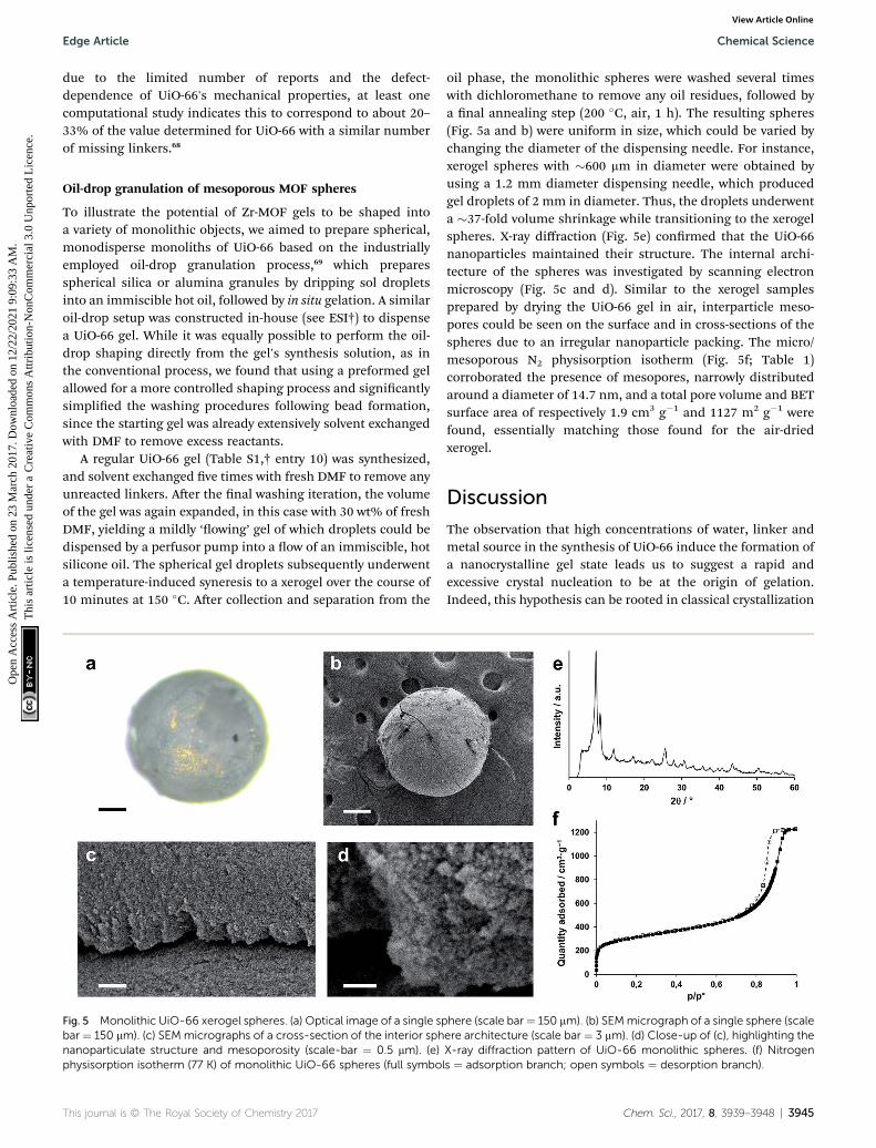
oil phase, the monolithic spheres were washed several timeswith dichloromethane to remove any oil residues, followed bya nal annealing step (200 �C, air, 1 h). The resulting spheres(Fig. 5a and b) were uniform in size, which could be varied bychanging the diameter of the dispensing needle. For instance,xerogel spheres with �600 mm in diameter were obtained byusing a 1.2 mm diameter dispensing needle, which producedgel droplets of 2 mm in diameter. Thus, the droplets underwenta �37-fold volume shrinkage while transitioning to the xerogelspheres. X-ray diffraction (Fig. 5e) conrmed that the UiO-66nanoparticles maintained their structure. The internal archi-tecture of the spheres was investigated by scanning electronmicroscopy (Fig. 5c and d). Similar to the xerogel samplesprepared by drying the UiO-66 gel in air, interparticle meso-pores could be seen on the surface and in cross-sections of thespheres due to an irregular nanoparticle packing. The micro/mesoporous N2 physisorption isotherm (Fig. 5f; Table 1)corroborated the presence of mesopores, narrowly distributedaround a diameter of 14.7 nm, and a total pore volume and BETsurface area of respectively 1.9 cm3 g�1 and 1127 m2 g�1 werefound, essentially matching those found for the air-driedxerogel.
Discussion
The observation that high concentrations of water, linker andmetal source in the synthesis of UiO-66 induce the formation ofa nanocrystalline gel state leads us to suggest a rapid andexcessive crystal nucleation to be at the origin of gelation.Indeed, this hypothesis can be rooted in classical crystallization
here (scale bar¼ 150 mm). (b) SEMmicrograph of a single sphere (scaleere architecture (scale bar ¼ 3 mm). (d) Close-up of (c), highlighting theX-ray diffraction pattern of UiO-66 monolithic spheres. (f) Nitrogenls ¼ adsorption branch; open symbols ¼ desorption branch).
Chem. Sci., 2017, 8, 3939–3948 | 3945

Fig. 6 Schematic overview of gel formation. (a) Synthesis in diluteconditions, with a limited amount of water leads to microcrystallineparticles. (b & c) High reactant and water concentration stimulatesformation of the [Zr6O4(OH)4]
12+ clusters and nucleation of the Zr-MOF (yellow stars). This leads to gel-like viscous colloidal suspensionsof Zr-MOF nanoparticles, in which further crystal growth is hampered.(b) At intermediate nanoparticle concentrations, ‘flowing’ gels can beobserved, (c) high nanoparticle concentrations lead to viscoelastic‘non-flowing’ gels with a network of weakly aggregated particlesthroughout the entire solvent volume. (d & e) Tuning the nanoparticleconcentration interconverts the system between these two states. (f)Solvent removal from the ‘non-flowing’ gels yields monolithic meso-porous xerogels or aerogels, consisting of randomly packednanoparticles.
Chemical Science Edge Article
Ope
n A
cces
s A
rtic
le. P
ublis
hed
on 2
3 M
arch
201
7. D
ownl
oade
d on
12/
22/2
021
9:09
:33
AM
. T
his
artic
le is
lice
nsed
und
er a
Cre
ativ
e C
omm
ons
Attr
ibut
ion-
Non
Com
mer
cial
3.0
Unp
orte
d L
icen
ce.
View Article Online
theory, which models the nucleation rate to be exponentiallydependent on the reactant supersaturation. Furthermore,a prerequisite for the UiO-66 framework to form is the forma-tion of its [Zr6O4(OH)4]
12+ clusters through hydrolysis of theemployed Zr-salt.59 The early formation and subsequent reten-tion of inorganic secondary building units during MOFsynthesis has been observed previously.70,71 The concentrationof water thus greatly inuences the crystallization of UiO-66. Forinstance, Schaate et al. reported how increasing the amount ofwater present in (diluted) synthesis media yielded progressivelysmaller UiO-66 crystallites, with sizes down to 14 nm.59 Simi-larly, Ragon et al. found UiO-66 to crystallize signicantly fasterin the presence of water and attributed this to an easierformation of the Zr6-clusters.50 The observed differences ingelation between ZrCl4 and ZrOCl2$8H2O can be interpreted ina similar fashion, since ZrOCl2$8H2O already is the primaryhydrolysis product of ZrCl4 and occurs as the tetranuclearcluster [Zr4(OH)8(H2O)16]Cl8$12(H2O); the latter can be consid-ered a direct precursor for the eventual Zr6-clusters in UiO-66.72
Thus, syntheses utilizing ZrOCl2$8H2O are likely less sensitiveto the addition of extra water due to its more advanced hydro-lysis degree.50 Whilst not explored here, others have observedthat the addition of modulators of increasing acidity results insmaller particle sizes for UiO-66, which could comprise analternative route to gelation.59,73,74
We propose gelation to be a direct consequence of the highconcentration of formed UiO-66 nanoparticles, which aggregateprimarily through non-covalent van der Waals interactions,although some degree of coordinative cross-linking or inter-growth between crystallites cannot be ruled out. The resultingcolloidal suspension contains a weakly bound network of solidsthroughout its entire volume, and effectively adopts a gel-likestate (Fig. 6). Because of a rapid decrease in reactant concen-tration, and concomitant increase in solution viscosity, furthergrowth of the UiO-66 crystallites is likely impeded, leading toa kinetically stable state. In more dilute systems, a limitednumber of nuclei rather continue to grow and precipitate asa microcrystalline MOF powder. While similar gelation mech-anisms have been proposed by others for MOF gels based on di-and trivalent cations,42,43,45,46 it should be noted that in several ofthese gels, additional, non-crystalline phases act as a binderbetween the MOF nanoparticles,43 or as a scaffold in which theyare embedded.45 In case of the UiO-66 gels presented here, theavailable evidence points to the absence of such phases (Fig. 3).
Associated with high particle concentrations in the UiO-66gel is a viscoelastic behaviour, with viscous ow occurringonly above a certain yield stress at which sufficient interparticleinteractions are overcome. The observed differences between‘non-owing’ and ‘owing’ gels nd their origin in a lowerviscosity and yield stress for the latter, likely resulting froma lower volume fraction of crystallites and/or larger crystallitesizes, allowing the gel to ow under gravitational forces.13 Post-synthetically manipulating the solid's concentration thus offersa straightforward means to controlling the viscosity and state ofthe system: applying shear forces, as in vortex mixing, enablesthe solid network of a ‘non-owing’ gel to be broken andredispersed in a larger solvent volume; the concentration of
3946 | Chem. Sci., 2017, 8, 3939–3948
particles is lowered, and the viscoelastic properties of thesystem resemble that of a ‘owing’ gel. Conversely, centrifuga-tion of a ‘owing’ gel, followed by removal of excess solventachieves the opposite transformation (Fig. 6), and allowed us toobtain ‘non-owing’ gels from as-synthesized ‘owing’ gels.
Since the inorganic Zr6-cluster is shared by many Zr-MOFs,we hypothesized that a rational choice of synthetic conditions,followed by application of the gelation principles outlined herefor UiO-66, would allow the extrapolation of gel formation toother Zr6-cluster systems. Starting from the routine used tosynthesize the UiO-66 monoliths (Table S1,† entry 10), ‘non-owing’ gels of the isoreticular MOFs UiO-66-NO2, UiO-66-NH2,UiO-66-(OH)2, UiO-67 and MOF-801 (ref. 75) were prepared bysimply substituting H2bdc for equimolar amounts of theirrespective linkers (Fig. S10†). MOF-808 (ref. 75) and NU-1000(ref. 52) are two Zr-MOFs based on respectively 1,3,5-benzene-tricarboxylate and 1,3,6,8-tetrakis(p-benzoate)pyrene as linkersand feature topologies that signicantly deviate from the face-centered cubic UiO-66 structure. Gels of these MOFs were stillreadily prepared by both increasing the concentration of reac-tants and including additional water relative to their originalsyntheses. In each case, an X-ray diffraction pattern (Fig. S11†)matching that of the desired phase, but with broad reectionsindicative of nanosized crystallites, was obtained. Furthermore,each of these gels could be solvent exchanged following theprocedure established for UiO-66, and transformed intomonolithic xerogels by drying in air (Fig. S10†).
This journal is © The Royal Society of Chemistry 2017
Edge Article Chemical Science
Ope
n A
cces
s A
rtic
le. P
ublis
hed
on 2
3 M
arch
201
7. D
ownl
oade
d on
12/
22/2
021
9:09
:33
AM
. T
his
artic
le is
lice
nsed
und
er a
Cre
ativ
e C
omm
ons
Attr
ibut
ion-
Non
Com
mer
cial
3.0
Unp
orte
d L
icen
ce.
View Article Online
Conclusions
In conclusion, a new method to structure UiO-66 at the meso-scale is presented, by steering the synthesis towards a MOF-nanoparticle based gel state. The UiO-66 gels could be trans-formed to hierarchically porous monoliths, both as xero- andaerogels, with pore volumes (2.09 cm3 g�1 and 1.66 cm3 g�1,respectively) far exceeding those of bulk UiO-66 powder. Thecombination of microporosity intrinsic to the UiO-66 structure,with mesoporosity derived from the gel state, is a signicantdifference in property between the bulk crystalline and mono-lithic states. Furthermore, the UiO-66 gel state can be exploitedto form shaped objects, as exemplied by the mesoporous,binder-free UiO-66 spheres prepared here by an industriallyrelevant oil-drop granulation. Since gelation is achieved inconditions which enhance the formation rate of the ubiquitousZr6-clusters, the principles outlined for preparing UiO-66 gelscan be extrapolated to form a variety of other Zr6-cluster basedMOF gels, as shown for isoreticular analogues of UiO-66, MOF-808 and NU-1000. Hence, the gels and monoliths presentedhere provide a step towards shaping Zr-MOF materials forapplications in catalysis or adsorption. Finally, the opticallytransparent nature of the xerogels may be of interest in thepreparation of transparent lms and coatings.
Acknowledgements
B. B., T. S. and I. S. acknowledge the FWO Flanders (doctoraland post-doctoral grants). T. W. acknowledges a post-doctoralgrant from the Swedish Research Council. T. D. B. acknowl-edges the Royal Society (University Research Fellowship) andTrinity Hall (University of Cambridge) for funding. S. B. and D.D. V. are grateful for funding by Belspo (IAP 7/05 P6/27) and bythe FWO Flanders. D. D. V. further acknowledges funding fromthe European Research Council (project H-CCAT). S. B.acknowledges nancial support from the European ResearchCouncil (ERC Starting Grant #335078-COLOURATOMS). Theauthors acknowledge Arnau Carne and Shuhei Furukawa forassistance with supercritical CO2 extraction, and CharlesGhesquiere for assistance in synthesis.
Notes and references
1 H. Furukawa, K. E. Cordova, M. O'Keeffe and O. M. Yaghi,Science, 2013, 341, 974–985.
2 P. Valvekens, F. Vermoortele and D. De Vos, Catal. Sci.Technol., 2013, 3, 1435–1445.
3 J. Liu, L. Chen, H. Cui, J. Zhang, L. Zhang and C.-Y. Su, Chem.Soc. Rev., 2014, 43, 6011–6061.
4 J.-R. Li, J. Sculley and H.-C. Zhou, Chem. Rev., 2012, 112, 869–932.
5 M. P. Suh, H. J. Park, T. K. Prasad and D.-W. Lim, Chem. Rev.,2012, 112, 782–835.
6 Y. He, W. Zhou, G. Qian and B. Chen, Chem. Soc. Rev., 2014,43, 5657–5678.
7 B. Van de Voorde, B. Bueken, J. Denayer and D. De Vos,Chem. Soc. Rev., 2014, 43, 5766–5788.
This journal is © The Royal Society of Chemistry 2017
8 P. Horcajada, R. Gref, T. Baati, P. K. Allan, G. Maurin,P. Couvreur, G. Ferey, R. E. Morris and C. Serre, Chem.Rev., 2012, 112, 1232–1268.
9 M. Gimenez-Marques, T. Hidalgo, C. Serre and P. Horcajada,Coord. Chem. Rev., 2016, 307, 342–360.
10 P. Ramaswamy, N. E. Wong and G. K. H. Shimizu, Chem. Soc.Rev., 2014, 43, 5913–5932.
11 L. E. Kreno, K. Leong, O. K. Farha, M. Allendorf, R. P. VanDuyne and J. T. Hupp, Chem. Rev., 2012, 112, 1105–1125.
12 V. Stavila, A. A. Talin and M. D. Allendorf, Chem. Soc. Rev.,2014, 43, 5994–6010.
13 M. J. Rhodes, Introduction to particle technology, Wiley-VHC,Weinheim, 2008.
14 F. Rezaei and P. Webley, Chem. Eng. Sci., 2009, 64, 5182–5191.
15 R. E. Morris, ChemPhysChem, 2008, 10, 327–329.16 D. Bradshaw, A. Garai and J. Huo, Chem. Soc. Rev., 2012, 41,
2344–2381.17 D. Bradshaw, S. El-Hankari and L. Lupica-Spagnolo, Chem.
Soc. Rev., 2014, 43, 5431–5443.18 S. Furukawa, J. Reboul, S. Diring, K. Sumida and S. Kitagawa,
Chem. Soc. Rev., 2014, 43, 5700–5734.19 Y. Lv, X. Tan and F. Svec, J. Sep. Sci., 2016, 40, 272–287.20 J. H. Cavka, S. Jakobsen, U. Olsbye, N. Guillou, C. Lamberti,
S. Bordiga and K. P. Lillerud, J. Am. Chem. Soc., 2008, 130,13850–13851.
21 T. Devic and C. Serre, Chem. Soc. Rev., 2014, 43, 6097–6115.22 Y. Bai, Y. Dou, L.-H. Xie, W. Rutledge, J.-R. Li and H.-C. Zhou,
Chem. Soc. Rev., 2016, 45, 2327–2367.23 Y.-Y. Fu, C.-X. Yang and X.-P. Yan, Chem. Commun., 2013, 49,
7162–7164.24 M. L. Pinto, S. Dias and J. Pires, ACS Appl. Mater. Interfaces,
2013, 5, 2360–2363.25 Z. Yan, J. Zheng, J. Chen, P. Tong, M. Lu, Z. Lin and L. Zhang,
J. Chromatogr. A, 2014, 1366, 45–53.26 I. Stassen, M. Styles, T. Van Assche, N. Campagnol,
J. Fransaer, J. Denayer, J.-C. Tan, P. Falcaro, D. De Vos andR. Ameloot, Chem. Mater., 2015, 27, 1801–1807.
27 E. Lopez-Maya, C. Montoro, L. M. Rodrıguez-Albelo,S. D. Aznar Cervantes, A. A. Lozano-Perez, J. L. Cenıs,E. Barea and J. A. R. Navarro, Angew. Chem., 2015, 127,6894–6898.
28 Y. Chen, X. Huang, S. Zhang, S. Li, S. Cao, X. Pei, J. Zhou,X. Feng and B. Wang, J. Am. Chem. Soc., 2016, 138, 10810–10813.
29 H. Zhu, Q. Zhang and S. Zhu, Chem.–Eur. J., 2016, 22, 8751–8755.
30 H. Zhu, X. Yang, E. D. Cranston and S. Zhu, Adv. Mater.,2016, 28, 7652–7657.
31 J. Zhao, D. T. Lee, R. W. Yaga, M. G. Hall, H. F. Barton,I. R. Woodward, C. J. Oldham, H. J. Walls, G. W. Petersonand G. N. Parsons, Angew. Chem., Int. Ed., 2016, 55, 13224–13228.
32 G. W. Peterson, J. B. DeCoste, T. G. Glover, Y. Huang,H. Jasuja and K. S. Walton, Microporous Mesoporous Mater.,2013, 179, 48–53.
Chem. Sci., 2017, 8, 3939–3948 | 3947

Chemical Science Edge Article
Ope
n A
cces
s A
rtic
le. P
ublis
hed
on 2
3 M
arch
201
7. D
ownl
oade
d on
12/
22/2
021
9:09
:33
AM
. T
his
artic
le is
lice
nsed
und
er a
Cre
ativ
e C
omm
ons
Attr
ibut
ion-
Non
Com
mer
cial
3.0
Unp
orte
d L
icen
ce.
View Article Online
33 J. B. Decoste and G. W. Peterson, Chem. Rev., 2014, 114,5695–5727.
34 B. Van de Voorde, I. Stassen, B. Bueken, F. Vermoortele,D. De Vos, R. Ameloot, J.-C. Tan and T. D. Bennett, J.Mater. Chem. A, 2015, 3, 1737–1742.
35 T. D. Bennett, T. K. Todorova, E. F. Baxter, D. G. Reid,C. Gervais, B. Bueken, B. Van de Voorde, D. De Vos,D. A. Keen and C. Mellot-Draznieks, Phys. Chem. Chem.Phys., 2016, 18, 2192–2201.
36 M. I. Nandasiri, S. R. Jambovane, B. P. McGrail, H. T. Schaefand S. K. Nune, Coord. Chem. Rev., 2016, 311, 38–52.
37 M. A. Moreira, J. C. Santos, A. F. P. Ferreira, J. M. Loureiro,F. Ragon, P. Horcajada, K.-E. Shim, Y.-K. Hwang,U.-H. Lee, J.-S. Chang, C. Serre and A. E. Rodrigues,Langmuir, 2012, 28, 5715–5723.
38 S.-N. Kim, Y.-R. Lee, S.-H. Hong, M.-S. Jang and W.-S. Ahn,Catal. Today, 2015, 245, 54–60.
39 N. Chanut, A. D. Wiersum, U.-H. Lee, Y. K. Hwang, F. Ragon,H. Chevreau, S. Bourrelly, B. Kuchta, J.-S. Chang, C. Serreand P. L. Llewellyn, Eur. J. Inorg. Chem., 2016, 2016, 4416–4423.
40 M. R. Lohe, M. Rose and S. Kaskel, Chem. Commun., 2009,6056–6058.
41 P. Sutar and T. K. Maji, Chem. Commun., 2016, 52, 8055–8074.
42 P. Horcajada, C. Serre, D. Grosso, C. Boissiere, S. Perruchas,C. Sanchez and G. Ferey, Adv. Mater., 2009, 21, 1931–1935.
43 L. Li, S. Xiang, S. Cao, J. Zhang, G. Ouyang, L. Chen andC.-Y. Su, Nat. Commun., 2013, 4, 1774.
44 W. Xia, X. Zhang, L. Xu, Y. Wang, J. Lin and R. Zou, RSC Adv.,2013, 3, 11007–11013.
45 A. K. Chaudhari, I. Han and J.-C. Tan, Adv. Mater., 2015, 27,4438–4446.
46 A. Mahmood, W. Xia, N. Mahmood, Q. Wang and R. Zou, Sci.Rep., 2015, 5, 10556.
47 M. Kandiah, S. Usseglio, S. Svelle, U. Olsbye, K. P. Lillerudand M. Tilset, J. Mater. Chem., 2010, 20, 9848–9851.
48 Q. Yang, S. Vaesen, F. Ragon, A. D. Wiersum, D. Wu, A. Lago,T. Devic, C. Martineau, F. Taulelle, P. L. Llewellyn, H. Jobic,C. Zhong, C. Serre, G. De Weireld and G. Maurin, Angew.Chem., Int. Ed., 2013, 52, 10316–10320.
49 F. Ragon, B. Campo, Q. Yang, C. Martineau, A. D. Wiersum,A. Lago, V. Guillerm, C. Hemsley, J. F. Eubank,M. Vishnuvarthan, F. Taulelle, P. Horcajada, A. Vimont,P. L. Llewellyn, M. Daturi, S. Devautour-Vinot, G. Maurin,C. Serre, T. Devic and G. Clet, J. Mater. Chem. A, 2015, 3,3294–3309.
50 F. Ragon, P. Horcajada, H. Chevreau, Y. K. Hwang, U.-H. Lee,S. R. Miller, T. Devic, J.-S. Chang and C. Serre, Inorg. Chem.,2014, 53, 2491–2500.
51 L. Liu, J. Zhang, H. Fang, L. Chen and C.-Y. Su, Chem.–AsianJ., 2016, 11, 2278–2283.
52 J. E. Mondloch, W. Bury, D. Fairen-Jimenez, S. Kwon,E. J. DeMarco, M. H. Weston, A. A. Sarjeant, S. T. Nguyen,
3948 | Chem. Sci., 2017, 8, 3939–3948
P. C. Stair, R. Q. Snurr, O. K. Farha and J. T. Hupp, J. Am.Chem. Soc., 2013, 135, 10294–10297.
53 A. K. Soper, Tech. Rep. RAL-TR-2011-013, 2011.54 A. K. Soper and E. R. Barney, J. Appl. Crystallogr., 2011, 44,
714–726.55 D. A. Keen, J. Appl. Crystallogr., 2001, 34, 172–177.56 B. Goris, W. Van den Broek, K. J. Batenburg, H. Heidari
Mezerji and S. Bals, Ultramicroscopy, 2012, 113, 120–130.57 J. Rouquerol, F. Rouquerol, and K. S. W. Sing, Absorption by
Powders and Porous Solids, Academic Press, London, 1999.58 W. C. Oliver and G. M. Pharr, J. Mater. Res., 2004, 19, 3–20.59 A. Schaate, P. Roy, A. Godt, J. Lippke, F. Waltz, M. Wiebcke
and P. Behrens, Chem.–Eur. J., 2011, 17, 6643–6651.60 B. Bueken, F. Vermoortele, M. J. Cliffe, M. T. Wharmby,
D. Foucher, J. Wieme, L. Vanduyuys, C. Martineau,N. Stock, F. Taulelle, V. Van Speybroeck, A. L. Goodwinand D. De Vos, Chem.–Eur. J., 2016, 22, 3264–3267.
61 A. E. Platero-Prats, A. Mavrandonakis, L. C. Gallington,Y. Liu, J. T. Hupp, O. K. Farha, C. J. Cramer andK. W. Chapman, J. Am. Chem. Soc., 2016, 138, 4178–4185.
62 T. D. Bennett, Y. Yue, P. Li, A. Qiao, H. Tao, N. G. Greaves,T. Richards, G. I. Lampronti, S. A. T. Redfern, F. Blanc,O. K. Farha, J. T. Hupp, A. K. Cheetham and D. A. Keen, J.Am. Chem. Soc., 2016, 138, 3484–3492.
63 M. Gateshki, V. Petkov, G. Williams, S. K. Pradhan andY. Ren, Phys. Rev. B: Condens. Matter Mater. Phys., 2005, 71,224107.
64 J. Aguado, D. P. Serrano, J. M. Escola and J. M. Rodrıguez,Microporous Mesoporous Mater., 2004, 75, 41–49.
65 J. Cravillon, S. M€unzer, S.-J. Lohmeier, A. Feldhoff, K. Huberand M. Wiebcke, Chem. Mater., 2009, 21, 1410–1412.
66 M. Taddei, K. C. Dumbgen, J. A. van Bokhoven andM. Ranocchiari, Chem. Commun., 2016, 52, 6411–6414.
67 G. C. Shearer, S. Chavan, J. Ethiraj, J. G. Vitillo, S. Svelle,U. Olsbye, C. Lamberti, S. Bordiga and K. P. Lillerud,Chem. Mater., 2014, 26, 4068–4071.
68 A. W. Thornton, R. Babarao, A. Jain, F. Trousselet andF.-X. Coudert, Dalton Trans., 2016, 45, 4352–4359.
69 F. Schuth and M. Hesse, in Handbook of HeterogeneousCatalysis, ed. G. Ertl, H. Knozinger, F. Schuth and J.Weitkamp, Wiley-VHC, Weinheim, Germany, 2008.
70 S. Surble, F. Millange, C. Serre, G. Ferey and R. I. Walton,Chem. Commun., 2006, 1518–1520.
71 F. Millange, M. I. Medina, N. Guillou, G. Ferey, K. M. Goldenand R. I. Walton, Angew. Chem., Int. Ed., 2010, 49, 763–766.
72 A. Cleareld and P. A. Vaughan, Acta Crystallogr., 1956, 9,555–558.
73 G. C. Shearer, S. Chavan, S. Bordiga, S. Svelle, U. Olsbye andK. P. Lillerud, Chem. Mater., 2016, 28, 3749–3761.
74 Z. Hu, I. Castano, S. Wang, Y. Wang, Y. Peng, Y. Qian, C. Chi,X. Wang and D. Zhao, Cryst. Growth Des., 2016, 16, 2295–2301.
75 H. Furukawa, F. Gandara, Y.-B. Zhang, J. Jiang, W. L. Queen,M. R. Hudson and O. M. Yaghi, J. Am. Chem. Soc., 2014, 136,4369–4381.
This journal is © The Royal Society of Chemistry 2017