Embed Size (px)
Citation preview
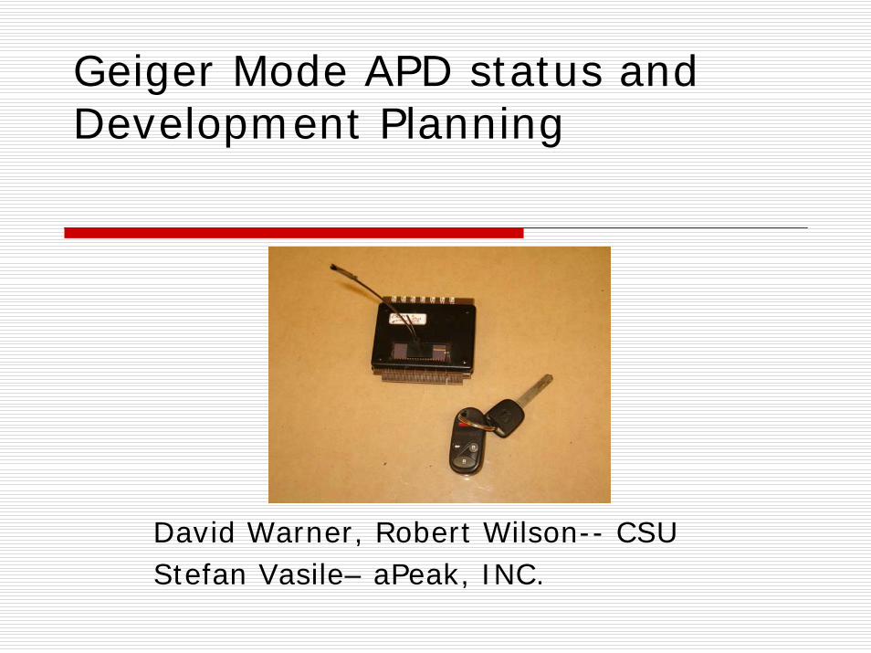
Geiger Mode APD status and Development Planning
David Warner, Robert Wilson-- CSUStefan Vasile– aPeak, INC.

David Warner- Colorado State University - 3/21/05
2
Overview
aPeak GPDs
SBIR Phase I Results Summary
Plans for Phase II
Conclusions

David Warner- Colorado State University - 3/21/05
3
aPeak GPDsaPeak GPD pixels are similar to SiPMT pixels, optimized to binary WLS fiber readout
7 150-micron diameter pixelsActive quenching to minimize pixel dead timeLow bias (~-13.6V)350 – 400 kHz DCR
Proprietary
David Warner- Colorado State University - 3/21/05
4
Advantages:
Minimal readout electronicsMinimal physical plant requirements
Low operating voltageHigh gain (typically >108)Potential for integrated active quenching and TTL readout
Potential for low cost and high reliabilityCMOS technology should result in high yieldsMinimal (no?) cooling requirements
e
David Warner- Colorado State University - 3/21/05
5
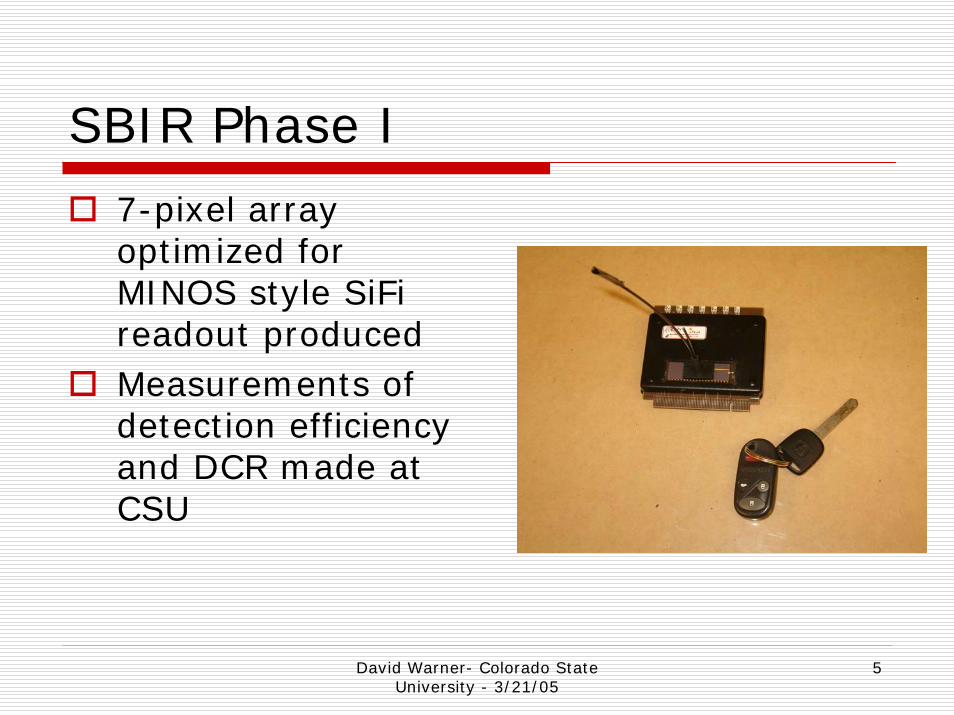
SBIR Phase I
7-pixel array optimized for MINOS style SiFireadout producedMeasurements of detection efficiency and DCR made at CSU
David Warner- Colorado State University - 3/21/05
6
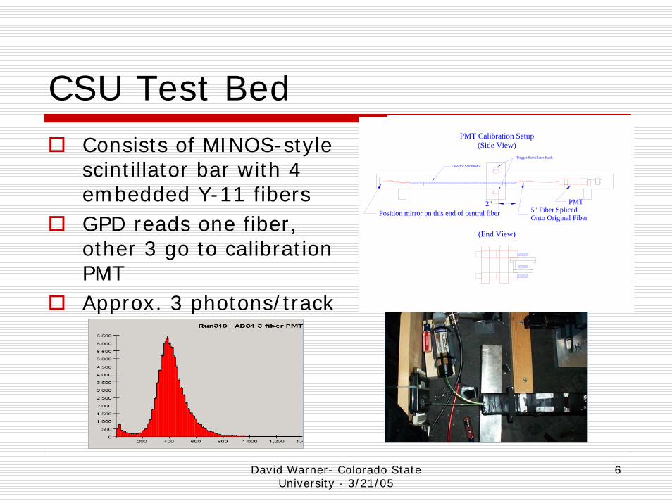
CSU Test BedConsists of MINOS-style scintillator bar with 4 embedded Y-11 fibersGPD reads one fiber, other 3 go to calibration PMTApprox. 3 photons/track
Trigger Scintillator Stack
Detector Scintillator
Position mirror on this end of central fiberPMT2"
5" Fiber SplicedOnto Original Fiber
PMT Calibration Setup(Side View)
(End View)

David Warner- Colorado State University - 3/21/05
7
Phase I Electronics SetupPhase I electronics based on LabVIEWreadout of CAMAC electronicsLimited to ~10 Hz data collection rateSignificant contribution to timing width from leading edge dciscrimination
Disc.Ch. T
Disc.Ch. B
2-FoldCoinc.
Disc.Y-11 Readout PMT (Calibration) CAMAC ADC
GPD Pixel (1-7) ActiveQuench
Trigger Scintillators
Test Bar
HV
End View & Electronics Block Diagram
Cosmic Ray Trigger(To ADC Gate andTDC Start)
Disc. CAMAC TDC
David Warner- Colorado State University - 3/21/05
8
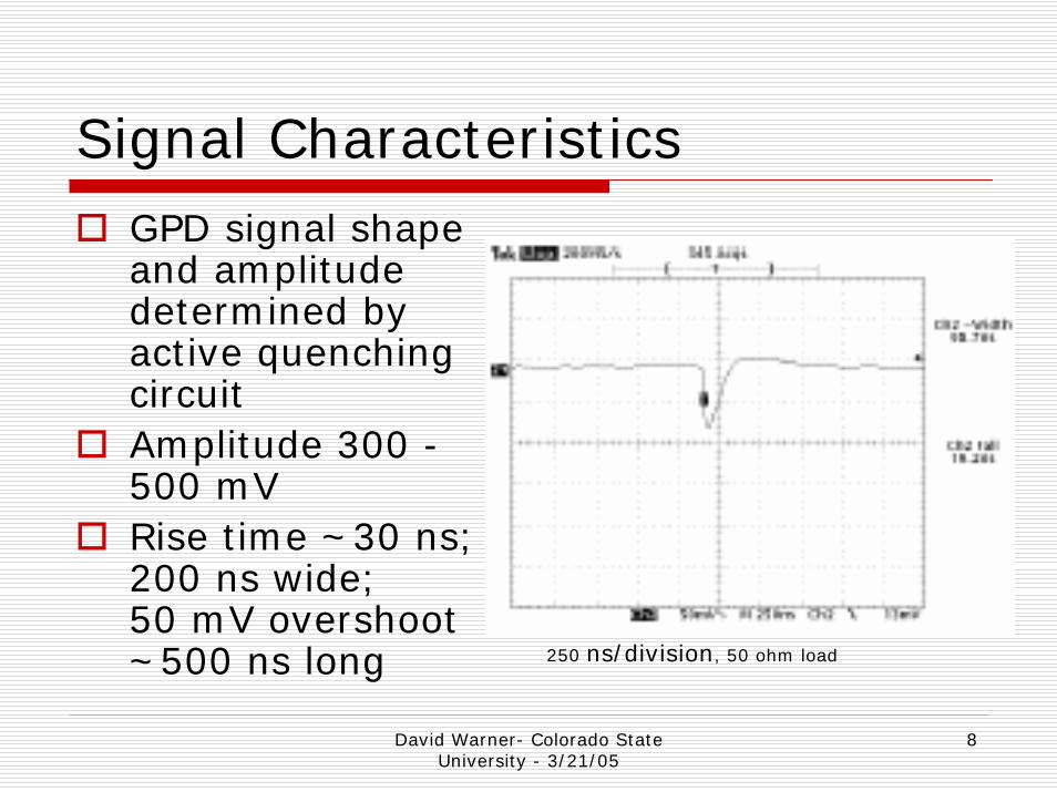
Signal CharacteristicsGPD signal shape and amplitude determined by active quenching circuitAmplitude 300 -500 mVRise time ~30 ns; 200 ns wide; 50 mV overshoot ~500 ns long 250 ns/division, 50 ohm load

David Warner- Colorado State University - 3/21/05
9
Dark count rateDCR varies strongly with bias voltageDCR also decreases with junction temperature–dependence still to be measuredBackground estimated from DCR measured before/after each run
Dark Count Rates
0200400600800
1000120014001600
13.4 13.5 13.6 13.7 13.8
Bias Voltage
Rat
e (k
Hz)
1234567

David Warner- Colorado State University - 3/21/05
10
Signal Time DistributionSignals arrive in an approximately 62.5 ns time windowBackground subtraction for DE calculations uses a random 62.5 ns window Apparent slope in background is an artifact due to masking of late events by single-hit TDC.
Single pixel TDC distribution (ped/overflow removed)
120,000 triggers in 48 hours~80,000 “good event” ( 3-fiber signal > 3
cts)Bias voltage -13.75 V
62.5 ns

David Warner- Colorado State University - 3/21/05
11
Measured Detection Efficiency
4
6
8
10
12
14
16
18
13.40 13.50 13.60 13.70 13.80
Bias, volts
DE,
%
0
10
20
30
40
50
60
70
13.40 13.50 13.60 13.70 13.80
Bias, volts
Clu
ster
DE,
%Single-pixel DE~2.5 to 3 photons/pixel/event
Combined cluster efficiencyMiddle– Best estimateTop- No background subtractionBottom- no hit number weighting

David Warner- Colorado State University - 3/21/05
12
Main lessons from Phase I~60% detection efficiency is not sufficient. Our Phase I experience has pointed the way to improvements---
Reduce DCR (Cooling?)
Improve active quenching circuit (AQC) (reduce 62.5 ns collection time)
Improve photon collection (bigger pixels, improved photocathode surface)
Better fiber coupling

David Warner- Colorado State University - 3/21/05
13
Phase II PlansaPeak was awarded an approximately $750K phase-II SBIR for GPD development in July 2004.
CSU awarded sub-contract of $167K for testing services
3 main development stages seen:Produce next-generation GPD run implementing planned improvements from Phase I arrays (Spring 2005)Produce 8-fiber readout chip with improved fiber coupling system (Summer 2005)Produce 64-fiber GPD arrays to mate with ILC muon system prototype (Winter/Spring ’05-’06)
David Warner- Colorado State University - 3/21/05
14
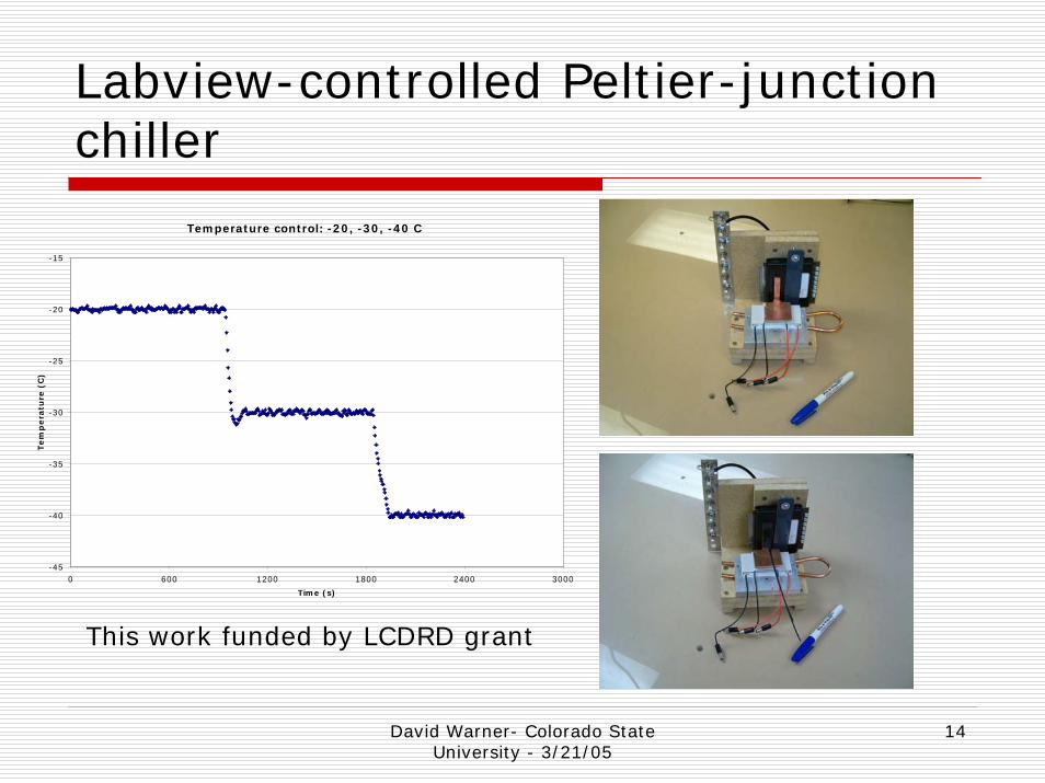
Labview-controlled Peltier-junction chiller
Temperature control: -20, -30, -40 C
-45
-40
-35
-30
-25
-20
-15
0 600 1200 1800 2400 3000
Time (s)
Tem
pera
ture
(C
)
This work funded by LCDRD grant
David Warner- Colorado State University - 3/21/05
15
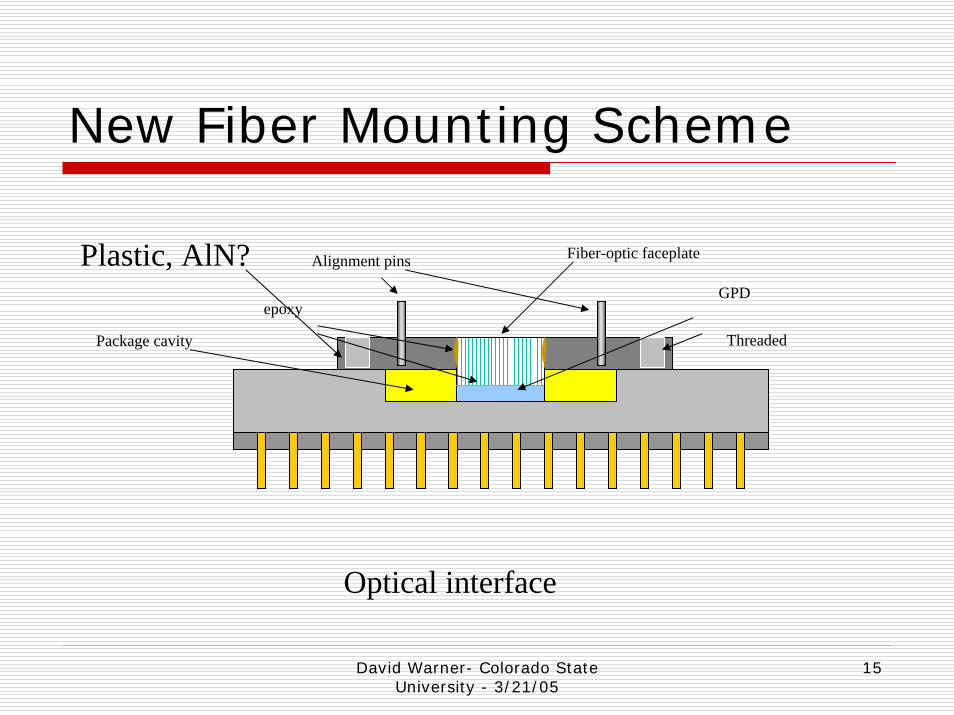
New Fiber Mounting Scheme
Alignment pins Fiber-optic faceplate
GPDepoxy
Package cavity Threaded
Plastic, AlN?
Optical interface

David Warner- Colorado State University - 3/21/05
16
Improvements to generation 2 pixel array/electronics
Pixel size increased to 170 micron diameterNew anti-reflective SiO2 coating on GPD surfaceNew AQC (10 ns risetime, ~50 ns reset time, -1.5V signal into 50 Ω load)Cooling junction (to -20oC?)Improved fiber mounting techniqueAQC will allow for testing ganged readout of all 7 pixels in a cluster or individual pixel readout
Sum of improvements are expected to yield detection efficiencies >90% per track

David Warner- Colorado State University - 3/21/05
17
0%
10%
20%
30%
40%
50%
60%
70%
80%
90%
100%
DE
larger GPD pixels
cooling to 0 oC
antireflecting layers
shorter quench/reset time
meas. @ 3.2 photons/150micron GPD
0%
10%
20%
30%
40%
50%
60%
70%
80%
90%
100%
DE
larger GPD pixels
cooling to 0 oC
antireflecting layers
shorter quench/reset time
meas. on Y11+ 7cluster 150micron GPD
Bench test @ 10kHz MINOS style μ setup @ 0.06 Hz
aPeak expectations for DE improvement
David Warner- Colorado State University - 3/21/05
18
Short-term Status
Peltier junction cooler ready at CSUTesting with Phase I GPDs to begin this week
New Generation-2 GPD array and AQC expected at CSU before April 1Preliminary DE measurements expected 6 weeks after delivery
David Warner- Colorado State University - 3/21/05
19
Plans for Generation 3 GPDsGeneration 3 “Muon system test” GPDs will include:
64 1-mm diameter fibers per chip (8 X 8 array)“ganged” readout of all 7 pixelsIntegrated signal conditioning– NIM logic level readoutPackaging to include cooling as required
Readout will initially be via gated 64-channel CAMAC hit register (LabVIEWdriven, slow data collection rate)
Other readout options may be implemented as needed for testing in muon system
David Warner- Colorado State University - 3/21/05
20
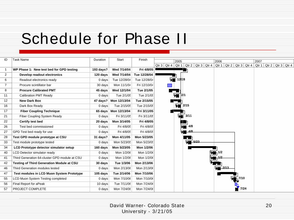
Schedule for Phase IIID Task Name Duration Start Finish
1 WP Phase 1: New test bed for GPD testing 193 days? Wed 7/14/04 Fri 4/8/052 Develop readout electronics 120 days Wed 7/14/04 Tue 12/28/046 Readout electronics ready 0 days Tue 12/28/04 Tue 12/28/047 Procure scintillator bar 30 days Mon 11/1/04 Fri 12/10/048 Procure Calibrated PMT 45 days Wed 12/1/04 Tue 2/1/0511 Calibration PMT Ready 0 days Tue 2/1/05 Tue 2/1/0512 New Dark Box 47 days? Mon 12/13/04 Tue 2/15/0516 Dark Box Ready 0 days Tue 2/15/05 Tue 2/15/0517 Fiber Coupling Technique 65 days Mon 12/13/04 Fri 3/11/0521 Fiber Coupling System Ready 0 days Fri 3/11/05 Fri 3/11/0522 Certify test bed 20 days Mon 3/14/05 Fri 4/8/0526 Test bed commissioned 0 days Fri 4/8/05 Fri 4/8/0527 GPD Test bed ready for use 0 days Fri 4/8/05 Fri 4/8/0528 Test GPD module prototype at CSU 31 days? Mon 4/11/05 Mon 5/23/0533 Test module prototype tested 0 days Mon 5/23/05 Mon 5/23/0534 LCD Prototype detector simulator setup 160 days Mon 5/23/05 Mon 1/2/0640 LCD Detector simulator ready 0 days Mon 1/2/06 Mon 1/2/0641 Third Generation 64-cluster GPD module at CSU 0 days Mon 1/2/06 Mon 1/2/0642 Testing of Third Generation Module at CSU 30 days Tue 1/3/06 Mon 2/13/0646 Third Generation modules tested 0 days Mon 2/13/06 Mon 2/13/0647 Test modules in LCD Muon System Prototype 105 days Tue 2/14/06 Mon 7/10/0655 LCD Muon System Testing completed 0 days Mon 7/10/06 Mon 7/10/0656 Final Report for aPeak 10 days Tue 7/11/06 Mon 7/24/0657 PROJECT COMPLETE 0 days Mon 7/24/06 Mon 7/24/06
12/28
2/1
2/15
3/11
4/84/8
5/23
1/21/2
2/13
7/10
7/24
Qtr 3 Qtr 4 Qtr 1 Qtr 2 Qtr 3 Qtr 4 Qtr 1 Qtr 2 Qtr 3 Qtr 4 Qtr 1 Qtr 2 Qtr 3 Qtr 42005 2006 2007
David Warner- Colorado State University - 3/21/05
21
Summary
Phase I GPD array testing lessons are being implemented in new Phase II devicesNew results should be coming shortlyWe expect to have GPD arrays for testing in a muon system in Feb. 06.We need to integrate further with the muon system to ensure compatibility with their test bed.