Embed Size (px)
Citation preview

Gecat Plastic Factory -‐GPF Dammam, SAUDI ARABIA Page 1
Gecat Plastic Factory -‐GPF Dammam, SAUDI ARABIA Page 2
INDEX
1. Earthwork
1.1. Surface Preparation 1.2. Anchor Trench
2. Liner Deployment
2.1. Panel identification 2.2. Deployment
3. Welding Procedure of HDPE Liner
3.1. Facts before starting welding 3.2. Trial seams 3.3. Hot Wedge Fusion welding
3.3.1. Welding Process 3.3.2. Welding Seam Geometry
3.4. Extrusion Fillet seams
3.4.1. Welding Process 3.4.2. Welding seam Geometry
4. HDPE Geomembrane Seams Testing Methods
4.1. Non-Destructive Seam Testing
4.1.1. Air Test 4.1.1.1. Equipment 4.1.1.2. Test Procedure 4.1.2. Vacuum Box Testing 4.1.2.1. Equipment 4.1.2.2. Test Procedure
4.1.3. Spark Test 4.1.3.1. Equipment 4.1.3.2. Test Procedure
4.2. Destructive Seam Testing
4.2.1. Shear Test 4.2.2. Peel Test
Gecat Plastic Factory -‐GPF Dammam, SAUDI ARABIA Page 3
HDPE Geomembrane Installation Procedure 1. Earthwork
1.1. Surface Preparation
a) The surface shall be prepared, prior to the liner installation, according to the
executive design guidelines. b) The surface to be lined shall be smooth and free of sharp objects and
stones, free of all foreign and organic material and debris of any kind. c) When the lining system includes compacted clay layer, the compacted
surface shall have no sharp changes or abrupt breaks in grade and shall be free of sharp materials.
d) Stones and rocks over 9.5 mm diameter shall not be allowed in the top 15 cm of soil sub grade.
e) It is recommended that the surface to be lined immediately after its preparation to avoid deterioration caused by rain, wind, loss of moisture or local traffic.
f) All surfaces shall be carefully inspected immediately before starting the lining works to verify if all above recommendations were followed.
1.2. Anchor Trench
a) The anchor trenches shall be excavated a little before the geomembrane placement to avoid rain damages and to avoid its desiccation in case of clay soil.
b) The anchor trench shall be excavated according to the design dimensions. c) The anchor trenches corners shall be slightly rounded to avoid sharp bends
in the geomembrane. d) The backfilling of the anchor trench shall be carefully to avoid the
geomembrane damage.
Gecat Plastic Factory -‐GPF Dammam, SAUDI ARABIA Page 4
2. Liner Deployment
Immediately before the liner deployment one must confirm that the surface to be lined is according to the recommendations of the surface preparation.
2.1. Panel identification:
Installation technician must register the number, the location and the placement date of each panel in the daily geomembrane installation quality control report.
2.2. Deployment:
a) The panels shall be placed according to its number and position in the
executive design. b) The geomembrane rolls shall be deployed vertically up and down the slope. c) The geomembrane panels shall be deployed in such a way that has a
minimum of wrinkle. d) Adequate temporary anchoring (sand bags or tires), that cause no damage
to the geomembrane, shall be placed to prevent uplift by the wind. In cases of high wind, continuous loading is recommended along the edges of the panels to minimize risk of wind flow under the panels.
e) If it is inevitable the vehicle traffic on the deployed geomembrane, one shall be foresee a protection layer above it (geotextile, extra geomembrane or soil layer), in such a way that the vehicle passes on that layer.
3. Welding Procedure of HDPE Liner
3.1. Facts before starting welding:
a) The seaming shall be done vertically up and down the slope. b) One recommends that no horizontal seam shall be done less than 1.50 m
from the toe of the slope or areas of potential stress concentration. c) In corners and odd-shaped geometric locations, the numbers of seams shall
be minimized. d) The overlaps between panels shall be 10 cm – 12 cm for fusion welding and
7.5 cm for extrusion welding. e) Immediately before welding start the overlaps shall be dry and clear.
Gecat Plastic Factory -‐GPF Dammam, SAUDI ARABIA Page 5
3.2. Trial seams:
a) Trial seams are done to verify the equipment and the operator. This verification shall be made at the beginning of each seaming period (start of day, midday and anytime equipment is turned off and allowed to cool down) for each seaming equipment used. Trial seams shall be done under the same conditions as panels’ seams.
b) The trial seam sample shall be 1 m long and 0.30 m wide, with the seam centered lengthwise. The seam overlap shall be 10 cm – 12 cm for hot wedge welding and 7.5 cm for extrusion welding.
c) From the welding sample five (2.5 cm wide and 30 cm long) specimens shall be cut to be tested respectively in shear and peel, using a field tenseometer. These samples must not fail in the test. If one specimen fails, the entire operation shall be repeated and the equipment and its operator should be accepted only when all lacking be corrected and the test is well done.
d) In cases of “fish mouths” or wrinkles at the seam overlaps, they shall be cut along the ridge of the wrinkle, in order to achieve a flat overlap. The geomembrane portion cut shall be seamed and any portion where overlap is inadequate shall be patched with an oval or round patch of the same geomembrane, extending a minimum of 15 cm beyond the cut in all directions.
3.3 Hot Wedge Fusion Welding:
a) Hot Wedge Fusion Welding is the primary method for field welding. Hot wedge equipment shall be self-propelled devices and shall be equipped with functioning temperature and speed controllers and monitors to assure proper control by the welding technician. Hot wedge type shall be equipped with pressure type seam testing.
b) Hot wedge unit consists of an electrically heated resistance element 1.75 inch (4.40 cm) wide copper wedge, controlled by a programmable controller, with an audible off-temperature alarm & variable speed drive unit which can operate between 0.1 and 16.0 feet/ minute (0.30 to 5.0 m/min).
c) The copper dual wedge (split wedge) has two weld-contacts with machine out space, 0.5 inch (1.25 cm) in the middle. This creates a double weld with an air space between the welds.
d) As the heated wedge passes between the linear overlap of 4 to 6 inches (10 to 15 cm), it melts and seams the liners.
e) Two pair of rollers with 0.5 inch (1.25 cm) gap in the middle of each roller, press the heated liner together. Rollers pressure is applied as the two liners converge at the tip of the wedge to form the final seam and also provides propulsion for the machine.
f) The air space between the welds can be used to evaluate seam quality & continuity of the seam by pressurizing the space with air & monitoring any drop in pressure that may signify a leak in the seam.
Gecat Plastic Factory -‐GPF Dammam, SAUDI ARABIA Page 6
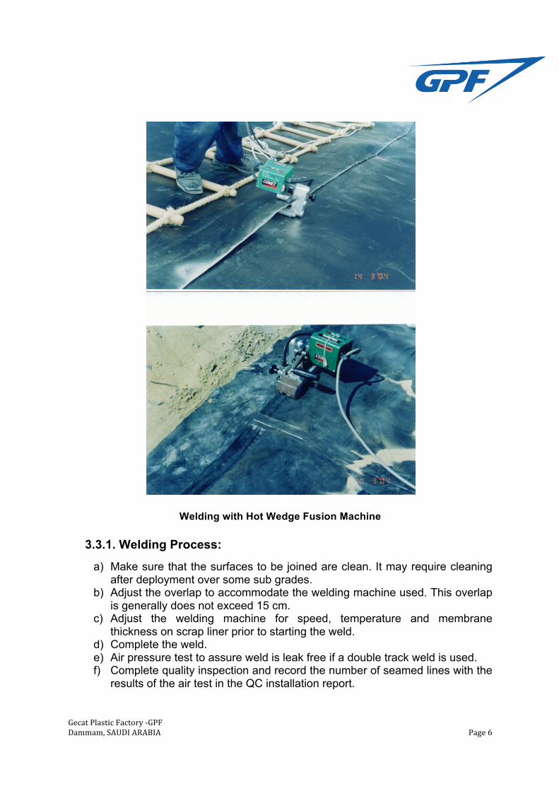
Welding with Hot Wedge Fusion Machine
3.3.1. Welding Process:
a) Make sure that the surfaces to be joined are clean. It may require cleaning after deployment over some sub grades.
b) Adjust the overlap to accommodate the welding machine used. This overlap is generally does not exceed 15 cm.
c) Adjust the welding machine for speed, temperature and membrane thickness on scrap liner prior to starting the weld.
d) Complete the weld. e) Air pressure test to assure weld is leak free if a double track weld is used. f) Complete quality inspection and record the number of seamed lines with the
results of the air test in the QC installation report.
Gecat Plastic Factory -‐GPF Dammam, SAUDI ARABIA Page 7
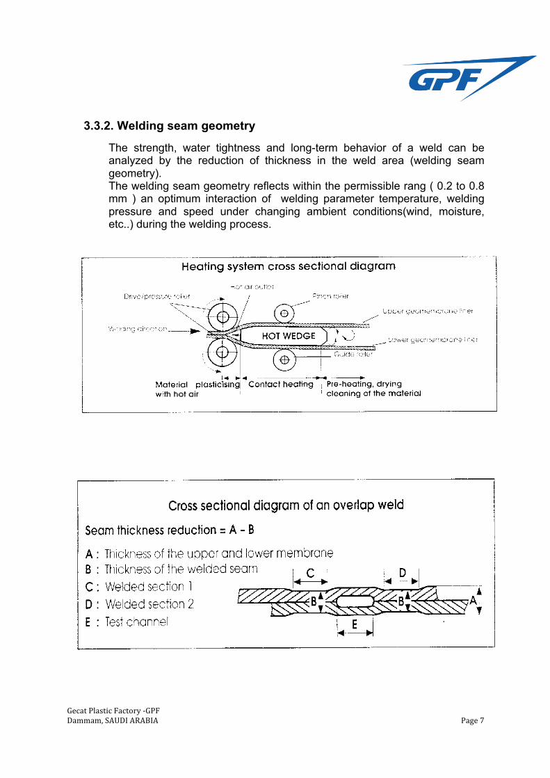
3.3.2. Welding seam geometry
The strength, water tightness and long-term behavior of a weld can be analyzed by the reduction of thickness in the weld area (welding seam geometry). The welding seam geometry reflects within the permissible rang ( 0.2 to 0.8 mm ) an optimum interaction of welding parameter temperature, welding pressure and speed under changing ambient conditions(wind, moisture, etc..) during the welding process.
Gecat Plastic Factory -‐GPF Dammam, SAUDI ARABIA Page 8
3.4 Extrusion Fillet seams
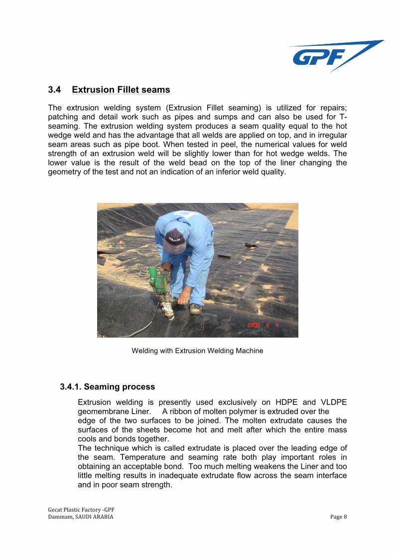
The extrusion welding system (Extrusion Fillet seaming) is utilized for repairs; patching and detail work such as pipes and sumps and can also be used for T- seaming. The extrusion welding system produces a seam quality equal to the hot wedge weld and has the advantage that all welds are applied on top, and in irregular seam areas such as pipe boot. When tested in peel, the numerical values for weld strength of an extrusion weld will be slightly lower than for hot wedge welds. The lower value is the result of the weld bead on the top of the liner changing the geometry of the test and not an indication of an inferior weld quality.
Welding with Extrusion Welding Machine
3.4.1. Seaming process
Extrusion welding is presently used exclusively on HDPE and VLDPE geomembrane Liner. A ribbon of molten polymer is extruded over the edge of the two surfaces to be joined. The molten extrudate causes the surfaces of the sheets become hot and melt after which the entire mass cools and bonds together. The technique which is called extrudate is placed over the leading edge of the seam. Temperature and seaming rate both play important roles in obtaining an acceptable bond. Too much melting weakens the Liner and too little melting results in inadequate extrudate flow across the seam interface and in poor seam strength.
Gecat Plastic Factory -‐GPF Dammam, SAUDI ARABIA Page 9
The actual seaming process is as follow:
a) The Geomembrane Liner sheet to be joined must be properly positioned such that approximately 7.5 cm to 15.0 cm (3 to 6 inches) of overlap exits.
b) HDPE liner material to be extruded must have a clean surface by removing the oxidation surface. This can be done by lightly grinding the weld surface with 60 or 80 grit discs. The grinding is performed parallel to the seam and to be controlled in a way that it does not extend more than 0.25 inch (0.6 cm) outside the area of the weld bead. Grinding shall be completed in no more than one hour before seaming takes place so that oxidized surface is not recreated prior to placement of extrudate and to prevent dirt from embedding itself in the patterned grooves. 1.5 mm liner or thicker liners should have the edge of the top sheet beveled by grinding to approximately an angle of 45o.
c) The HDPE liner material to be extrusion welded must be temporarily bonded to hold the material in place until the extrusion weld bead cools and attains full strength. This is normally accomplished by performing an automatic or hand air tack weld.
d) The extrusion welder should be purged and cleaned of all degraded plastics prior to the start of seaming.
e) Extruder in the form of molten, highly viscous fluid must be deposited over the overlapped Liner. The center of the extruder must be located directly over the edge of the upper Liner. The extruder should cover the third grind marks on each side of the upper and lower Liner to within 0.25 inch (0.6 cm) of the outside borders. The weld bead appearance is smooth and uniform.
f) The extrudate thickness should be approximately equal or greater than the specified sheet thickness measured from the top or crown of the extruder.
g) All extrusion welds should be non-destructively tested by the vacuum testing. Area which cannot be non-destructively tested should be capped.
h) Destructive test can be conducted when seam lengths are adequate.
Gecat Plastic Factory -‐GPF Dammam, SAUDI ARABIA Page 10
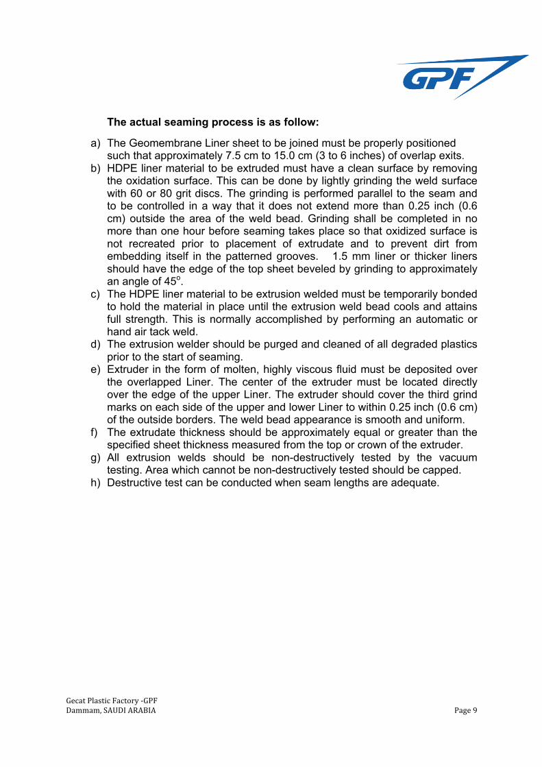
3.4.2. Welding Seam Geometry
Upper Liner
Lower Liner
Extruder Width
75 mm Min
12 – 25 mm 12 – 25 mm
Upper Liner
Extrudate
Gecat Plastic Factory -‐GPF Dammam, SAUDI ARABIA Page 11
4. HDPE Geomembrane Seams Testing Methods 4.1. Non-Destructive Seam Testing All field seams shall be tested over its full length. Non-destructive tests check the integrity of the weld by using air-pressure testing to the fusion welds, vacuum testing to extrusion welds and sometimes the spark test for some extrusion welds.
4.1.1. Air Test
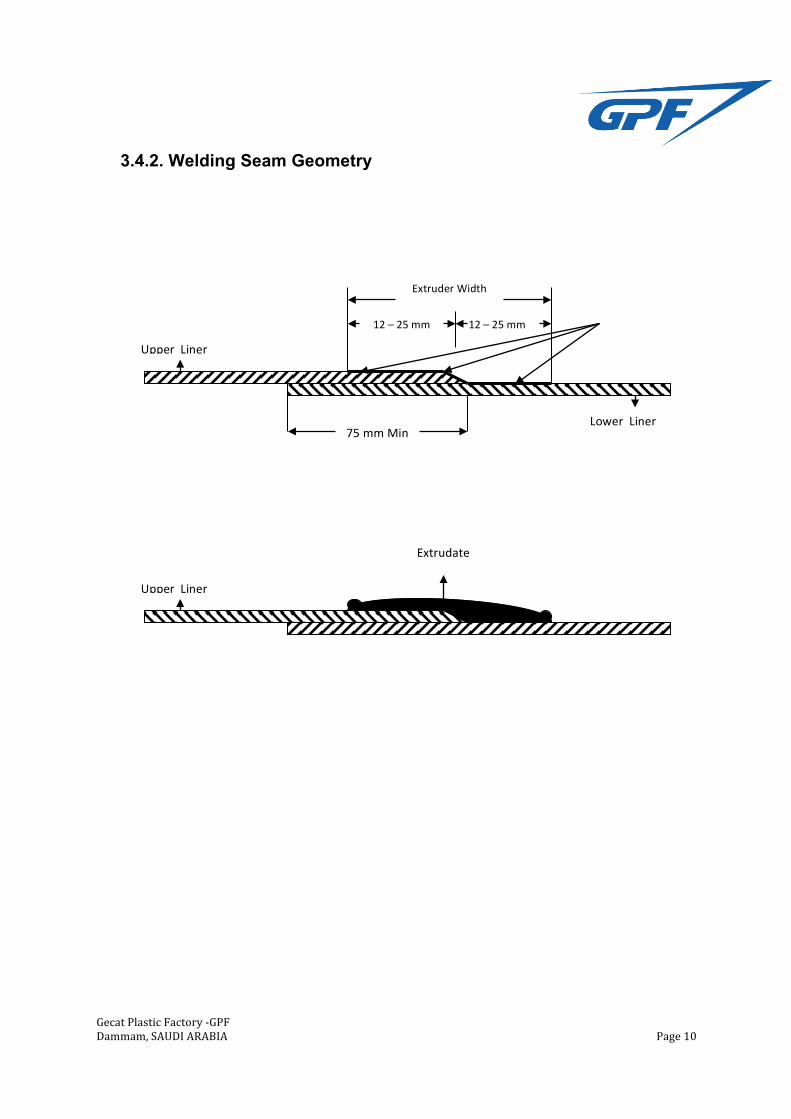
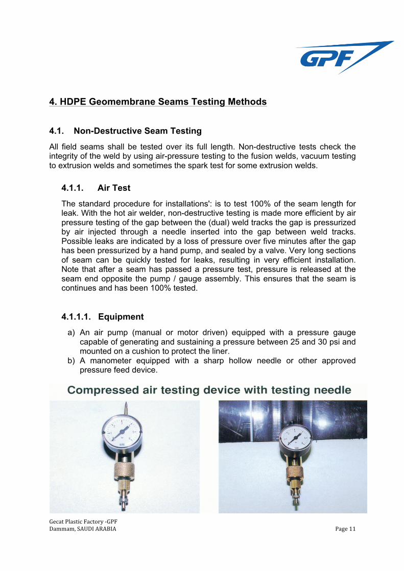
The standard procedure for installations': is to test 100% of the seam length for leak. With the hot air welder, non-destructive testing is made more efficient by air pressure testing of the gap between the (dual) weld tracks the gap is pressurized by air injected through a needle inserted into the gap between weld tracks. Possible leaks are indicated by a loss of pressure over five minutes after the gap has been pressurized by a hand pump, and sealed by a valve. Very long sections of seam can be quickly tested for leaks, resulting in very efficient installation. Note that after a seam has passed a pressure test, pressure is released at the seam end opposite the pump / gauge assembly. This ensures that the seam is continues and has been 100% tested.
4.1.1.1. Equipment
a) An air pump (manual or motor driven) equipped with a pressure gauge capable of generating and sustaining a pressure between 25 and 30 psi and mounted on a cushion to protect the liner.
b) A manometer equipped with a sharp hollow needle or other approved pressure feed device.
Gecat Plastic Factory -‐GPF Dammam, SAUDI ARABIA Page 12
4.1.1.2. Test Procedure
a) Seal one end of the seam to be tested. b) Insert needle or other approved pressure feed device through the sealed end
of the channel created by the double wedge fusion weld. c) Energized air pump to verify the unobstructed passage of air through the
channel. d) Seal the other end of the channel. e) Energize the air pump to a pressure between 25 and 30 psi, and read
pressure inserted into the air chamber of the seam. Allow the pressure to stabilize and if necessary, re-pressurize to between 25 and 30 psi and sustain it for approximately from (2 minutes to 5 minutes)
f) If the loss of pressure exceeds 3 psi, or pressure does not stabilize, locate faulty area, repair and retest.
g) Remove needle or other approved pressure feed device and seal.
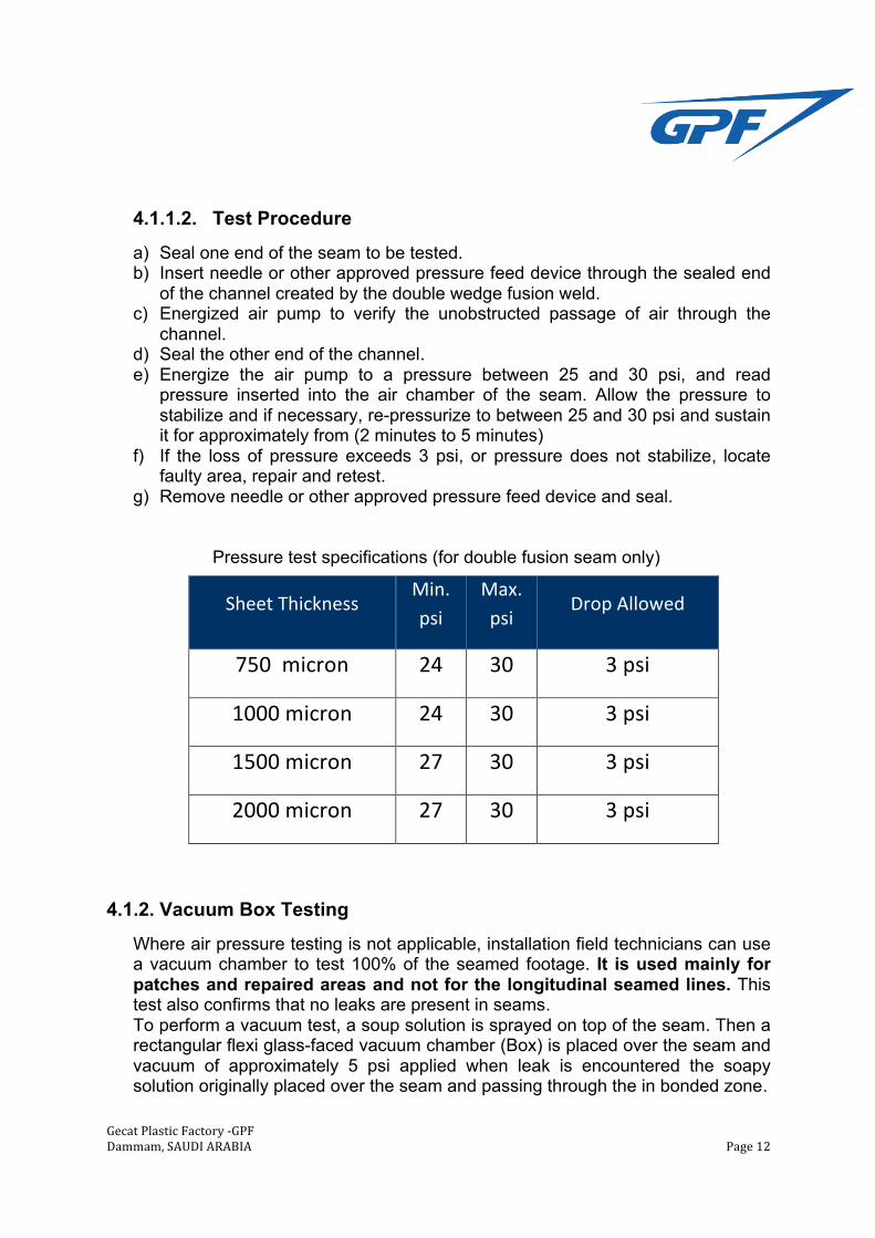
Pressure test specifications (for double fusion seam only)
Sheet Thickness Min. psi
Max. psi
Drop Allowed
750 micron 24 30 3 psi
1000 micron 24 30 3 psi
1500 micron 27 30 3 psi
2000 micron 27 30 3 psi
4.1.2. Vacuum Box Testing
Where air pressure testing is not applicable, installation field technicians can use a vacuum chamber to test 100% of the seamed footage. It is used mainly for patches and repaired areas and not for the longitudinal seamed lines. This test also confirms that no leaks are present in seams. To perform a vacuum test, a soup solution is sprayed on top of the seam. Then a rectangular flexi glass-faced vacuum chamber (Box) is placed over the seam and vacuum of approximately 5 psi applied when leak is encountered the soapy solution originally placed over the seam and passing through the in bonded zone.
Gecat Plastic Factory -‐GPF Dammam, SAUDI ARABIA Page 13
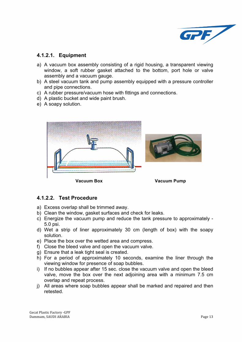
4.1.2.1. Equipment a) A vacuum box assembly consisting of a rigid housing, a transparent viewing
window, a soft rubber gasket attached to the bottom, port hole or valve assembly and a vacuum gauge.
b) A steel vacuum tank and pump assembly equipped with a pressure controller and pipe connections.
c) A rubber pressure/vacuum hose with fittings and connections. d) A plastic bucket and wide paint brush. e) A soapy solution.
Vacuum Box Vacuum Pump
4.1.2.2. Test Procedure
a) Excess overlap shall be trimmed away. b) Clean the window, gasket surfaces and check for leaks. c) Energize the vacuum pump and reduce the tank pressure to approximately -
5.0 psi. d) Wet a strip of liner approximately 30 cm (length of box) with the soapy
solution. e) Place the box over the wetted area and compress. f) Close the bleed valve and open the vacuum valve. g) Ensure that a leak tight seal is created. h) For a period of approximately 10 seconds, examine the liner through the
viewing window for presence of soap bubbles. i) If no bubbles appear after 15 sec. close the vacuum valve and open the bleed
valve, move the box over the next adjoining area with a minimum 7.5 cm overlap and repeat process.
j) All areas where soap bubbles appear shall be marked and repaired and then retested.
Gecat Plastic Factory -‐GPF Dammam, SAUDI ARABIA Page 14
4.1.3. Spark Test
It is used when the seam cannot be tested by vacuum test, as irregular surfaces or curves. In this test, one puts a thin conductor wire through the superior geomembrane edged with the diameter smaller than its thickness, so that when the extrusion weld is done it keeps in the seam. A device similar to a metal brush ,connected to a 20 KV electric source, shall be guided through the seam. If there is defect in the seam there will be a spark.
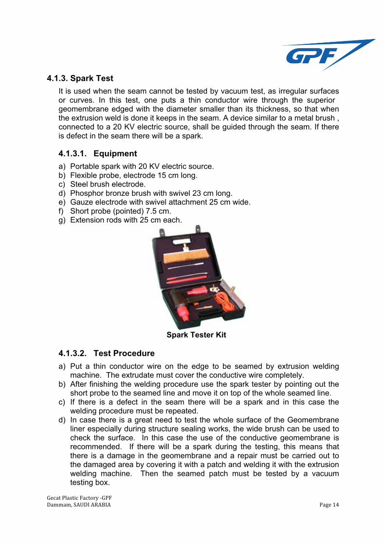
4.1.3.1. Equipment
a) Portable spark with 20 KV electric source. b) Flexible probe, electrode 15 cm long. c) Steel brush electrode. d) Phosphor bronze brush with swivel 23 cm long. e) Gauze electrode with swivel attachment 25 cm wide. f) Short probe (pointed) 7.5 cm. g) Extension rods with 25 cm each.
Spark Tester Kit
4.1.3.2. Test Procedure
a) Put a thin conductor wire on the edge to be seamed by extrusion welding machine. The extrudate must cover the conductive wire completely.
b) After finishing the welding procedure use the spark tester by pointing out the short probe to the seamed line and move it on top of the whole seamed line.
c) If there is a defect in the seam there will be a spark and in this case the welding procedure must be repeated.
d) In case there is a great need to test the whole surface of the Geomembrane liner especially during structure sealing works, the wide brush can be used to check the surface. In this case the use of the conductive geomembrane is recommended. If there will be a spark during the testing, this means that there is a damage in the geomembrane and a repair must be carried out to the damaged area by covering it with a patch and welding it with the extrusion welding machine. Then the seamed patch must be tested by a vacuum testing box.
Gecat Plastic Factory -‐GPF Dammam, SAUDI ARABIA Page 15
4.2. Destructive Seam Testing
The purpose of these tests is to evaluate the seam strength by specimens 2.5 cm wide and 30 cm long, with the seam centered lengthwise. The tests shall be done to five specimens. Destructive tests should be minimized to preserve the integrity of the liner. Usually these test are done once per 150 m of seam length, but is recommended to follow the design specifications. These tests shall follow the standards recommendations ASTM D-4437, ASTM D-413, ASTM D-3083 and ASTM D-638.
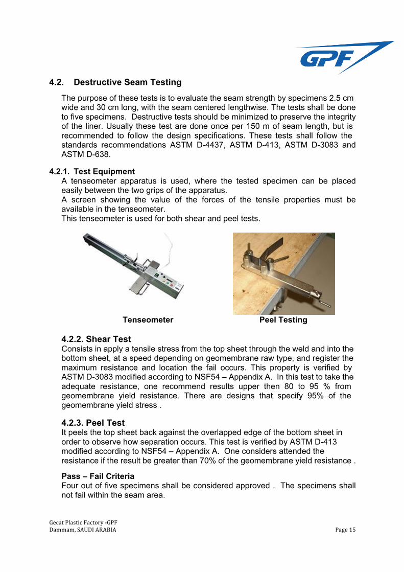
4.2.1. Test Equipment A tenseometer apparatus is used, where the tested specimen can be placed easily between the two grips of the apparatus. A screen showing the value of the forces of the tensile properties must be available in the tenseometer. This tenseometer is used for both shear and peel tests.
Tenseometer Peel Testing 4.2.2. Shear Test Consists in apply a tensile stress from the top sheet through the weld and into the bottom sheet, at a speed depending on geomembrane raw type, and register the maximum resistance and location the fail occurs. This property is verified by ASTM D-3083 modified according to NSF54 – Appendix A. In this test to take the adequate resistance, one recommend results upper then 80 to 95 % from geomembrane yield resistance. There are designs that specify 95% of the geomembrane yield stress .
4.2.3. Peel Test It peels the top sheet back against the overlapped edge of the bottom sheet in order to observe how separation occurs. This test is verified by ASTM D-413 modified according to NSF54 – Appendix A. One considers attended the resistance if the result be greater than 70% of the geomembrane yield resistance .
Pass – Fail Criteria Four out of five specimens shall be considered approved . The specimens shall not fail within the seam area.