Embed Size (px)
Citation preview

Gear Pumps and MotorsTechnical Catalog
Series 26 PumpsSeries 26 MotorsSeries L2 Pumps


4 EATON Gear Pumps and Motors E-PUGE-MC001-E1 June 2011
Table of Contents
Series 26 Pumps
Features ........................................................................................................................................................................5
General Specifications and Performance Data ..............................................................................................................7
Performance Data Charts ..............................................................................................................................................5
Standard Catalog Assemblies - Dimensions................................................................................................................11
Order Numbers............................................................................................................................................................12
Optional Configurations ..............................................................................................................................................14
Component Parts - Dimensions ..................................................................................................................................15
Model Code - Single ....................................................................................................................................................18
Model Code - Multiple ................................................................................................................................................19
Side-Load Applications ................................................................................................................................................21
Load Sensing Priority Valve..........................................................................................................................................23
Series 26 Motors
General Specifications ................................................................................................................................................24
Performance Data........................................................................................................................................................25
Model Code - Single....................................................................................................................................................26
Series L2 Pumps
General Specifications and Performance Data ............................................................................................................27
Performance Data Charts ............................................................................................................................................28
Standard Catalog Assemblies - Dimensions ..............................................................................................................30
Order Numbers ..........................................................................................................................................................31
Optional Configurations ..............................................................................................................................................33
Component Parts - Dimensions ..................................................................................................................................34
Model Code - Single....................................................................................................................................................37
Model Code - Multiple ................................................................................................................................................38

5EATON Gear Pumps and Motors E-PUGE-MC001-E1 June 2011
Series 26 PumpFeatures
Quiet Operation
• The 13-tooth gears, versus10 teeth in previouspumps, minimizes the flowripple. This reduces noiseas well as vibration.
• The improved trap reliefsnot only increase power,they also help keep oilflowing smoothly to reducenoise.
Improved Efficiency
• Improved bearing lubrica-tion system uses inlet oilinstead of high pressureoil, improving volumetricefficiency for more poweroutput.
• The highly polished shaftand gears improvemechanical efficiency andreduce wear on thesecomponents, adding to theservice life and reliability ofthe pump.
• The optimized trapped oilrelief areas help reducepressure ripple for quieteroperation. This alsodecreases the input powerrequirements.
Field Reversible
• The innovative new wearplate permits simple fieldreversibility of the pumpdirection. Simply open thepump, switch the drivegear and idler gear, reposi-tion the plug and reassem-ble. No extra parts areneeded.
Interchangeability
• The Series 26 Gear Pumphas been designed toretrofit equipment usingthe B1 and B2 GearPumps. Extra shafts, port-ing, and mounting configu-rations, as well as 13 avail-able displacements, giveyou the choices you needfor an easy conversion tothis superior pump.
Pressures to 3500 PSIand flow to 24.1 GPM
6
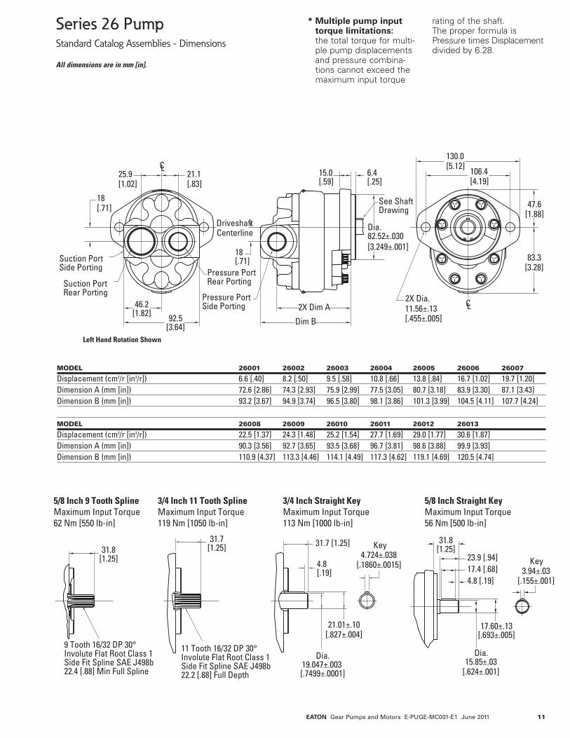
Series 26 PumpGeneral Specifications and Performance Data
Displacement cm3/r [in3/r] 6,6 8,2 9,5 10,8 13,8 16,7 19,7[.40] [.50] [.58] [.66] [.84] [1.02] [1.20]
Max. Intermittent Pressure bar [PSI] 241 241 241 241 241 241 241[3500] [3500] [3500] [3500] [3500] [3500] [3500]
Rated Speed (RPM) 3600 3600 3600 3600 3600 3600 3200Minimum Output Flow at 207 bar [3000 PSI] 20,1 25,0 29,5 33,7 43,5 55,3 57,9and Rated Speed LPM [GPM] [5.3] [6.6] [7.8] [8.9] [11.5] [14.6] [15.3]Input Power at 207 bar [3000 PSI] and 9,7 11,9 14,1 15,5 20,0 22,0 26,2Rated Speed and Cont. Pressure kW [HP] [13.0] [15.9] [18.9] [20.8] [26.8] [29,4] [35.2]
Displacement cm3/r [in3/r] 22,5 24,3 25,2 27,7 29,0 30,6[1.37] [1.48] [1.54] [1.69] [1.77] [1.87]
Max. Intermittent Pressure bar [PSI] 241 241 241 241 234 224[3500] [3500] [3500] [3500] [3400] [3250]
Rated Speed (RPM) 3000 3000 3000 3000 3000 3000Minimum Output Flow at 207 bar [3000 PSI] 62,1 67,0 69,7 76,5 79,9 84,4and Rated Speed LPM [GPM] [16.4] [17.7] [18.4] [20.2] [21.1] [22.3]Input Power at 207 bar [3000 PSI] and 27,3 30,5 31,0 33,4 35,4 37,4Rated Speed and Cont. Pressure kW [HP] [36.6] [40.9] [41.6] [44.8] [47.4] [50.1]
The performance data in the table above and the following graphs was collected using a mineral base oil with a viscosity of 133 SUS at 49°C [120°F].
Rotation Field ReversibleMounting Flange SAE A 2 BoltMax. Continuous Pressure† 210 bar [3000 PSI]*Max. Intermittent Pressure†† 240 bar [3500 PSI]**Minimum Speed at Continuous Pressure 750 RPMMaximum Rotating Torque at 0 Pressure 4 Nm [36 lb-in]Maximum Continuous Operating Temperature 105°C [220°F]Minimum Continuous Oil Viscocity 5.7 cSt [45 SUS]Minimum Operating Temperature -29°C [-20°F]Maximum Inlet Vacuum at Operating Condition 0,8 bar Abs. [11.6 psi Abs.]
† Continuous - pump may be run continuously at these ratings.
†† Intermittent - intermittent operation, 10% of every minute.
* 30.6 cm3/rev. [1.87 in3/rev.] displacement max. continuous pressure is 190 bar [2750 PSI].
** 30.6 cm3/rev. [1.87 in3/rev.] displacement max. intermittent pressure is 224 bar [3250 PSI].
For side load limits consult your Eaton representative.
Ordering Information
Catalog Assemblies CrossReference
Standard catalog assemblies arebuilt from high production partsand are the most economicalpump assemblies available in thisseries. The standard assembly
order number is a preassignedpart number and may be used toorder the specific standardassembly (see pages 10–13). Thefar right column lists the B1 or B2pump replaced by the Series 26pump.
EATON Gear Pumps and Motors E-PUGE-MC001-E1 June 2011

7
Series 26 PumpPerformance Data Charts
0 1000 2000 3000 3600
Speed RPM
13 [17]
12 [16]
11 [15]
10 [13]
9 [12]
8 [11]
7 [9]
6 [8]
5 [7]
4 [5]
3 [4]
2 [3]
1 [1.3]
0
0 1000 2000 3000 3600
Flow
inL/
min
.[G
PM]
@13
8ba
r[2
000
PSI]
6,56–19,68 cm3/rev [.40–1.20 in3/rev]
8,20 cm3/rev [.50 in3/rev]
6,56 cm3/rev [.40 in3/rev]
Speed RPM
0
10
20
30
40
50
60
70
[0]
[5]
[10]
[15]
0 1000 2000 3000 3600
Speed RPM
13 [17]
12 [16]
11 [15]
10 [13]
9 [12]
8 [11]
7 [9]
6 [8]
5 [7]
4 [5]
3 [4]
2 [3]
1 [1.3]
0
Inpu
tkW
[HP]
Inpu
tkW
[HP]
Inpu
tkW
[HP]
0 1000 2000 3000 3600
Speed RPM
26 [35]
24 [32]
22 [29.5]
20 [27]
18 [24]
16 [21.5]
14 [19]
12 [16]
10 [13]
8 [11]
6 [8]
4 [5]
2 [3]
0
9,51 cm3/rev [.58 in3/rev
8,2[.50 ]9.5[.5
8]10
,8[.6
6]13,8
[.84]
19,7
[1.20
]16
,7[1.
02]
6,6 [.401]
35 Bar [500 PSI]69 Bar [1000 PSI]104 Bar [1500 PSI]
138Bar [20
00PSI]
172
Bar [2500
PSI]
207 Bar
[3000
PSI]
35 Bar [500 PSI]
35 Bar [500 PSI]
69 Bar [1000 PSI]
69 Bar [1000 PSI]104 Bar [1500 PSI]
104 Bar [1500 PSI]
138 Bar [20
00PSI]
138 Bar [2000 PSI]
172
Bar[25
00PS
I]
172 Bar [2500 PSI]
207 Bar
[3000
PSI]
207Bar [30
00PSI]
EATON Gear Pumps and Motors E-PUGE-MC001-E1 June 2011

8
0 1000 2000 3000 3600
Speed RPM
13,78 cm3/rev [.84 in3/rev]26 [35]
24 [32]
22 [29.5]
20 [27]
18 [24]
16 [21.5]
14 [19]
12 [16]
10 [13]
8 [11]
6 [8]
4 [5]
2 [3]
0
5[raB5300 P ]IS
1[raB96
000]ISP
raB481
[15]00
13
]ISP0002[raB8
1
]ISP0052[raB272
]ISP0003[raB70
0 1000 2000 3200
Speed RPM
28 [37.5]
26 [35]
24 [32]
22 [29.5]
20 [27]
18 [24]
16 [21.5]
14 [19]
12 [16]
10 [13]
8 [11]
6 [5]
4 [4]
2 [3]
0
16,73 cm3/rev [1.02 in3/rev]
3
]ISP005[raB5
96
]ISP0001[raB
401
]ISP0051[raB
1
]ISP0002[raB83
271
]ISP0052[raB702
]ISP0003[raB
0 1000 2000 3200
Speed RPM
28 [37.5]
26 [35]
24 [32]
22 [29.5]
20 [27]
18 [24]
16 [21.5]
14 [19]
12 [16]
10 [13]
8 [11]
6 [5]
4 [4]
2 [3]
0
19,68 cm3/rev [1.20 in3/rev]
01[raB96
00 P]IS
051[raB401
0 P]IS
SP0002[raB831
I]]ISP0052[raB271
5[raB5300
]ISP
P0003[raB702
SI]
0 1000 2000 3000 3600
Speed RPM
10,82 cm3/rev [.66 in3/rev] 26 [35]
24 [32]
22 [29.5]
20 [27]
18 [24]
16 [21.5]
14 [19]
12 [16]
10 [13]
8 [11]
6 [8]
4 [5]
2 [3]
0
]ISP005[raB53
]ISP0001[raB96
]ISP0051[raB401
]ISP0002[raB831
]ISP0052[raB271
]ISP0003[raB702
Inpu
tkW
[HP]
Inpu
tkW
[HP]
Inpu
tkW
[HP]
Inpu
tkW
[HP]
Series 26 PumpPerformance Data Charts
EATON Gear Pumps and Motors E-PUGE-MC001-E1 June 2011

9
0 1000 2000 3000
28 [37.5]
26 [35]
24 [32]
22 [29.5]
20 [27]
18 [24]
16 [21]
14 [19]
12 [16]
10 [13]
8 [11]
6 [5]
4 [4]
2 [2.7]
0
22,47 cm3/rev [1.37 in3/rev]
0 1000 2000 3000
22,47–30,67 cm3/rev [1.37–1.87 in3/rev]
0
10
20
30
40
50
60
70
[0]
[10]
[5]
[15]
[20]
80
90
22,5 [1.37]
24,3 [1.48]
25,2 [1.54]
27,7 [1.69] 29,0 [1.77] 30,6 [1.87]
0 1000 2000 3000
32 [43]
30 [40]
28 [37.5]
26 [35]
24 [32]
22 [29.5]
20 [27]
18 [24]
16 [21]
14 [19]
12 [16]
10 [13]
8 [11]
6 [5]
4 [4]
2 [3]
0
24,27 cm3/rev [1.48 in3/rev]
207 B
ar[3
000 P
SI]
0 1000 2000 3000
32,84 [44]
29,84 [40]
26,86 [36]
23,87 [32]
20,89 [28]
17,90 [24]
14,92 [20]
11,94 [16]
8,95 [12]
5,97 [8]
2,98 [4]
0
25,56 cm3/rev [1.54 in3/rev]
Flow
inL/
min
.[G
PM]
@13
8ba
r[2
000
PSSI
]
Inpu
tkW
[HP]
Inpu
tkW
[HP]
Inpu
tkW
[HP]
Speed RPM Speed RPM
Speed RPM Speed RPM
172 Ba
r [25
00PS
I]
138 Bar
[2000
PSI]
104 Bar [15
00PSI]
69 Bar [1000 PSI]
35 Bar [500 PSI]
35 Bar [500 PSI]69 Bar [1000 PSI]104
Bar [1500
PSI]
138 Bar
[2000
PSI]
172 Ba
r[25
00PS
I]
207 B
ar[3
000 P
SI]
35 Bar [500 PSI]69 Bar [1000 PSI]
104 Bar [15
00PSI]
138 Bar
[2000
PSI]
172 B
ar[2
500 P
SI]
207
Bar
[300
0 PSI
]
Series 26 PumpPerformance Data Charts
EATON Gear Pumps and Motors E-PUGE-MC001-E1 June 2011

10
Series 26 PumpPerformance Data Charts
0 1000 2000 3000
Speed RPM
40 [54]
38 [51]
36 [48]
34 [45.5]
32 [43]
30 [40]
28 [37.5]
26 [35]
24 [32]
22 [29.5]
20 [27]
18 [24]
16 [21]
14 [19]
12 [16]
10 [13]
8 [11]
6 [5]
4 [4]
2 [3]
0
27,72 cm3/rev [1.69 in3/rev] 29,03 cm3/rev [1.77 in3/rev] 30,67 cm3/rev [1.87 in3/rev]
Inpu
tkW
[HP]
Inpu
tkW
[HP]
Inpu
tkW
[HP]
0 1000 2000 3000
Speed RPM
40 [54]
38 [51]
36 [48]
34 [45.5]
32 [43]
30 [40]
28 [37.5]
26 [35]
24 [32]
22 [29.5]
20 [27]
18 [24]
16 [21]
14 [19]
12 [16]
10 [13]
8 [11]
6 [5]
4 [4]
2 [3]
00 1000 2000 3000
Speed RPM
40 [54]
38 [51]
36 [48]
34 [45.5]
32 [43]
30 [40]
28 [37.5]
26 [35]
24 [32]
22 [29.5]
20 [27]
18 [24]
16 [21]
14 [19]
12 [16]
10 [13]
8 [11]
6 [5]
4 [4]
2 [3]
0
207 b
ar[3
00PS
I]
35 Bar [500 PSI]69 Bar [1000 PSI]10
4 Bar[15
00PSI]13
8 Bar
[2000
PSI]
172 B
ar[2
500 P
SI]
207 b
ar[3
00PS
I]
35 Bar [500 PSI]69 Bar [1000 PSI]10
4 Bar[15
00PSI]
138 Ba
r[20
00PS
I]
172 B
ar[2
500 P
SI]
207
bar
[300
PSI]
35 Bar [500 PSI]69
Bar [1000
PSI]
104 Bar
[1500
PSI]
138 B
ar[2
000 P
SI]
172 B
ar[2
500 P
SI]
EATON Gear Pumps and Motors E-PUGE-MC001-E1 June 2011
11
Pressure PortRear Porting Suction Port
Rear Porting
25.9 [1.02]
21.1 [.83]
Driveshaft Centerline
18 [.71]
Suction PortSide Porting
46.2 [1.82] 92.5
[3.64] Left Hand Rotation Shown
83.3 [3.28]
47.6 [1.88]
130.0 [5.12]
106.4 [4.19]
18 [.71]
2X Dim A Pressure PortSide Porting
Dim B
See Shaft Drawing
Dia. 82.52±.030 [3.249±.001]
6.4 [.25]
15.0 [.59]
2X Dia. 11.56±.13 [.455±.005]
3
CL
CL
31.8 [1.25]
9 Tooth 16/32 DP 30°Involute Flat Root Class 1 Side Fit Spline SAE J498b 22.4 [.88] Min Full Spline
31.7 [1.25]
11 Tooth 16/32 DP 30°Involute Flat Root Class 1 Side Fit Spline SAE J498b 22.2 [.88] Full Depth
4.8 [.19]
Dia. 19.047±.003 [.7499±.0001]
31.7 [1.25] Key 4.724±.038
[.1860±.0015]
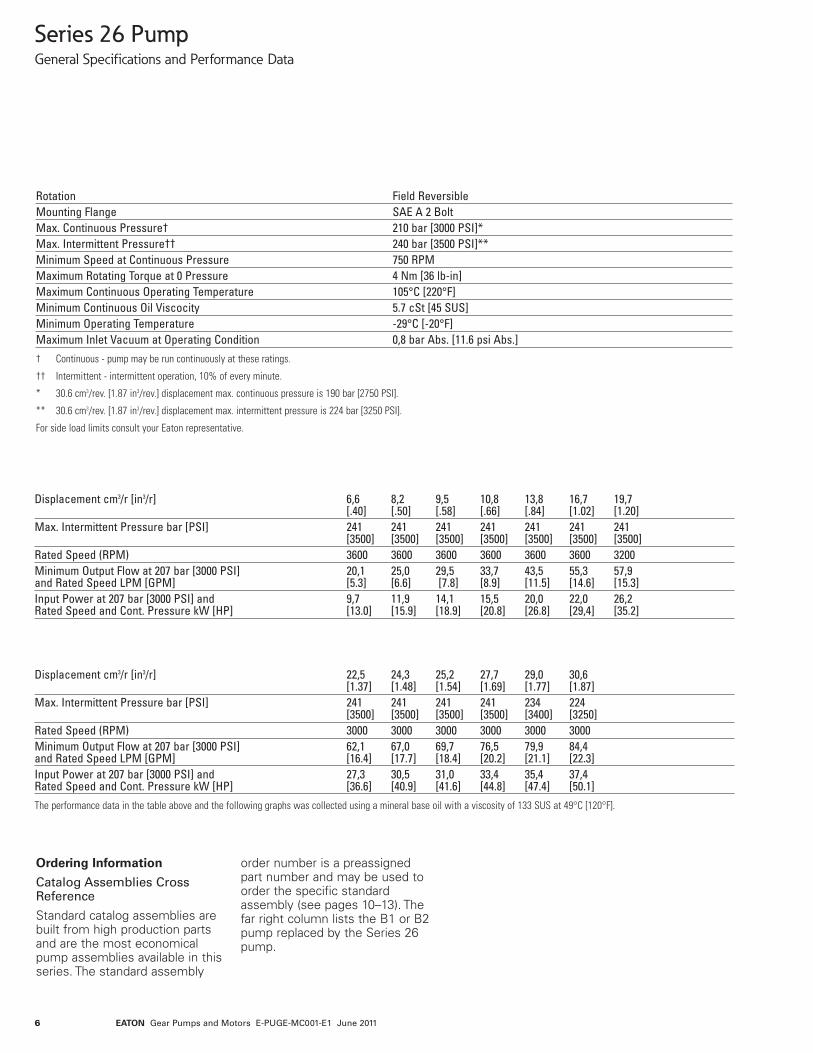
5/8 Inch 9 Tooth Spline Maximum Input Torque62 Nm [550 lb-in]
3/4 Inch 11 Tooth Spline Maximum Input Torque 119 Nm [1050 lb-in]
3/4 Inch Straight Key Maximum Input Torque113 Nm [1000 lb-in]
5/8 Inch Straight Key Maximum Input Torque 56 Nm [500 lb-in]
Key 3.94±.03
[.155±.001]
17.60±.13 [.693±.005]
Dia. 15.85±.03
[.624±.001]
31.8 [1.25]
23.9 [.94] 17.4 [.68] 4.8 [.19]
21.01±.10 [.827±.004]
Series 26 PumpStandard Catalog Assemblies - Dimensions
All dimensions are in mm [in].
MODEL 26001 26002 26003 26004 26005 26006 26007
Displacement (cm3/r [in3/r]) 6.6 [.40] 8.2 [.50] 9.5 [.58] 10.8 [.66] 13.8 [.84] 16.7 [1.02] 19.7 [1.20]Dimension A (mm [in]) 72.6 [2.86] 74.3 [2.93] 75.9 [2.99] 77.5 [3.05] 80.7 [3.18] 83.9 [3.30] 87.1 [3.43]Dimension B (mm [in]) 93.2 [3.67] 94.9 [3.74] 96.5 [3.80] 98.1 [3.86] 101.3 [3.99] 104.5 [4.11] 107.7 [4.24]
MODEL 26008 26009 26010 26011 26012 26013
Displacement (cm3/r [in3/r]) 22.5 [1.37] 24.3 [1.48] 25.2 [1.54] 27.7 [1.69] 29.0 [1.77] 30.6 [1.87]Dimension A (mm [in]) 90.3 [3.56] 92.7 [3.65] 93.5 [3.68] 96.7 [3.81] 98.6 [3.88] 99.9 [3.93]Dimension B (mm [in]) 110.9 [4.37] 113.3 [4.46] 114.1 [4.49] 117.3 [4.62] 119.1 [4.69] 120.5 [4.74]
* Multiple pump inputtorque limitations:the total torque for multi-ple pump displacementsand pressure combina-tions cannot exceed themaximum input torque
rating of the shaft.The proper formula isPressure times Displacementdivided by 6.28.
EATON Gear Pumps and Motors E-PUGE-MC001-E1 June 2011

12
Series 26 PumpOrder Numbers
RIGHT HAND LEFT HAND SAE O-RING SAE O-RINGROTATION ROTATION PORT PRESSURE SUCTIONPRODUCT NO PRODUCT NO SHAFT LOCATION PORT SIZE PORT SIZE REPLACES
Model 26001 – 6,6 cm3/r [.40 in3/r] Displacement26001-RZG 26001-LZG 5/8 Keyed Side 7/8-14 UNF-2B 1-1/16-12 UN-2B 24300-RZA/LZA26001-RZH 26001-LZH 5/8 Keyed Rear 7/8-14 UNF-2B 1-1/16-12 UN-2B 24300-RZC/LZD26001-RZJ 26001-LZJ 5/8 9 T Spline Side 7/8-14 UNF-2B 1-1/16-12 UN-2B 24300-RZB/LZA26001-RZK 26001-LZK 5/8 9 T Spline Rear 7/8-14 UNF-2B 1-1/16-12 UN-2B 24300-RZD/LZEModel 26002 – 8,2 cm3/r [.50 in3/r] Displacement26002-RZA 26002-LZA 3/4 11T Spline Side 7/8-14 UNF-2B 1-5/16-12 UN-2B 25300-RSA/LSA26002-RZB 26002-LZB 3/4 11T Spline Rear 7/8-14 UNF-2B 1-5/16-12 UN-2B 25300-RSB/LSB26002-RZC 26002-LZC 3/4 Keyed Side 7/8-14 UNF-2B 1-5/16-12 UN-2B 25300-RSC/LSC26002-RZD 26002-LZD 3/4 Keyed Rear 7/8-14 UNF-2B 1-5/16-12 UN-2B 25300-RSD/LSD26002-RZE 26002-LZE 5/8 9 T Spline Side 7/8-14 UNF-2B 1-5/16-12 UN-2B 25300-RSE/LSE26002-RZF 26002-LZF 5/8 9 T Spline Rear 7/8-14 UNF-2B 1-5/16-12 UN-2B 25300-RSF/LSF26002-RZG 26002-LZG 5/8 Keyed Side 7/8-14 UNF-2B 1-1/16-12 UN-2B 24301-RZC/LZA26002-RZH 26002-LZH 5/8 Keyed Rear 7/8-14 UNF-2B 1-1/16-12 UN-2B 24301-RZG/LZG26002-RZJ 26002-LZJ 5/8 9 T Spline Side 7/8-14 UNF-2B 1-1/16-12 UN-2B 24301-RZD/LZB26002-RZK 26002-LZK 5/8 9 T Spline Rear 7/8-14 UNF-2B 1-1/16-12 UN-2B 24301-RZH/LZHModel 26003 – 9,5 cm3/r [.58 in3/r] Displacement26003-RZG 26003-LZG 5/8 Keyed Side 7/8-14 UNF-2B 1-1/16-12 UN-2B 24302-RZB/LZB26003-RZH 26003-LZH 5/8 Keyed Rear 7/8-14 UNF-2B 1-1/16-12 UN-2B 24302-RZC/LZD26003-RZJ 26003-LZJ 5/8 9 T Spline Side 7/8-14 UNF-2B 1-1/16-12 UN-2B 24302-RZA/LZA26003-RZK 26003-LZK 5/8 9 T Spline Rear 7/8-14 UNF-2B 1-1/16-12 UN-2B 24302-RZD/LZEModel 26004 – 10,8 cm3/r [.66 in3/r] Displacement26004-RZA 26004-LZA 3/4 11T Spline Side 7/8-14 UNF-2B 1-5/16-12 UN-2B 25301-RSA/LSA26004-RZB 26004-LZB 3/4 11T Spline Rear 7/8-14 UNF-2B 1-5/16-12 UN-2B 25301-RSB/LSB26004-RZC 26004-LZC 3/4 Keyed Side 7/8-14 UNF-2B 1-5/16-12 UN-2B 25301-RSC/LSC26004-RZD 26004-LZD 3/4 Keyed Rear 7/8-14 UNF-2B 1-5/16-12 UN-2B 25301-RSD/LSD26004-RZE 26004-LZE 5/8 9 T Spline Side 7/8-14 UNF-2B 1-5/16-12 UN-2B 25301-RSE/LSE26004-RZF 26004-LZF 5/8 9 T Spline Rear 7/8-14 UNF-2B 1-5/16-12 UN-2B 25301-RSF/LSF26004-RZG 26004-LZG 5/8 Keyed Side 7/8-14 UNF-2B 1-1/16-12 UN-2B 24303-RZB/LZB26004-RZH 26004-LZH 5/8 Keyed Rear 7/8-14 UNF-2B 1-1/16-12 UN-2B 24303-RZE/LZF26004-RZJ 26004-LZJ 5/8 9 T Spline Side 7/8-14 UNF-2B 1-1/16-12 UN-2B 24303-RZD/LZA26004-RZK 26004-LZK 5/8 9 T Spline Rear 7/8-14 UNF-2B 1-1/16-12 UN-2B 24303-RZF/LZGModel 26005 – 13,8 cm3/r [.84 in3/r] Displacement26005-RZA 26005-LZA 3/4 11T Spline Side 7/8-14 UNF-2B 1-5/16-12 UN-2B 25302-RSA/LSA26005-RZB 26005-LZB 3/4 11T Spline Rear 7/8-14 UNF-2B 1-5/16-12 UN-2B 25302-RSB/LSB26005-RZC 26005-LZC 3/4 Keyed Side 7/8-14 UNF-2B 1-5/16-12 UN-2B 25302-RSC/LSC26005-RZD 26005-LZD 3/4 Keyed Rear 7/8-14 UNF-2B 1-5/16-12 UN-2B 25302-RSD/LSD26005-RZE 26005-LZE 5/8 9 T Spline Side 7/8-14 UNF-2B 1-5/16-12 UN-2B 25302-RSE/LSE26005-RZF 26005-LZF 5/8 9 T Spline Rear 7/8-14 UNF-2B 1-5/16-12 UN-2B 25302-RSF/LSF26005-RZG 26005-LZG 5/8 Keyed Side 7/8-14 UNF-2B 1-1/16-12 UN-2B 24304-RZC/LZA26005-RZH 26005-LZH 5/8 Keyed Rear 7/8-14 UNF-2B 1-1/16-12 UN-2B 24304-RZG/LZF26005-RZJ 26005-LZJ 5/8 9 T Spline Side 7/8-14 UNF-2B 1-1/16-12 UN-2B 24304-RZD/LZB26005-RZK 26005-LZK 5/8 9 T Spline Rear 7/8-14 UNF-2B 1-1/16-12 UN-2B 24304-RZH/LZGModel 26006 – 16,7 cm3/r [1.02 in3/r] Displacement26006-RZA 26006-LZA 3/4 11T Spline Side 7/8-14 UNF-2B 1-5/16-12 UN-2B 25303-RSA/LSA26006-RZB 26006-LZB 3/4 11T Spline Rear 7/8-14 UNF-2B 1-5/16-12 UN-2B 25303-RSB/LSB26006-RZC 26006-LZC 3/4 Keyed Side 7/8-14 UNF-2B 1-5/16-12 UN-2B 25303-RSC/LSC26006-RZD 26006-LZD 3/4 Keyed Rear 7/8-14 UNF-2B 1-5/16-12 UN-2B 25303-RSD/LSD26006-RZE 26006-LZE 5/8 9 T Spline Side 7/8-14 UNF-2B 1-5/16-12 UN-2B 25303-RSE/LSE26006-RZF 26006-LZF 5/8 9 T Spline Rear 7/8-14 UNF-2B 1-5/16-12 UN-2B 25303-RSF/LSF26006-RZG 26006-LZG 5/8 Keyed Side 7/8-14 UNF-2B 1-1/16-12 UN-2B 24305-RZC/LZA26006-RZH 26006-LZH 5/8 Keyed Rear 7/8-14 UNF-2B 1-1/16-12 UN-2B 24305-RZG/-LZF26006-RZJ 26006-LZJ 5/8 9 T Spline Side 7/8-14 UNF-2B 1-1/16-12 UN-2B 24305-RZD/LZB26006-RZK 26006-LZK 5/8 9 T Spline Rear 7/8-14 UNF-2B 1-1/16-12 UN-2B 24305-RZH/LZG
* 5/8 9 T Spline has a maximum allowable input torque of 62 Nm [550 lb-in].
** 5/8 Keyed shaft has a maximum allowable input torque of 56 Nm [500 lb-in].
EATON Gear Pumps and Motors E-PUGE-MC001-E1 June 2011

13
Series 26 PumpOrder Numbers
RIGHT HAND LEFT HAND SAE O-RING SAE O-RINGROTATION ROTATION PORT PRESSURE SUCTIONPRODUCT NO PRODUCT NO SHAFT LOCATION PORT SIZE PORT SIZE REPLACES
Model 26007 – 19,7 cm3/r [1.20 in3/r] Displacement26007-RZA 26007-LZA 3/4 11T Spline Side 7/8-14 UNF-2B 1-5/16-12 UN-2B 25304-RSA/LSA26007-RZB 26007-LZB 3/4 11T Spline Rear 7/8-14 UNF-2B 1-5/16-12 UN-2B 25304-RSB/LSB26007-RZC 26007-LZC 3/4 Keyed Side 7/8-14 UNF-2B 1-5/16-12 UN-2B 25304-RSC/LSC26007-RZD 26007-LZD 3/4 Keyed Rear 7/8-14 UNF-2B 1-5/16-12 UN-2B 25304-RSD/LSD26007-RZE 26007-LZE *5/8 9 T Spline Side 7/8-14 UNF-2B 1-5/16-12 UN-2B 25304-RSE/LSE26007-RZF 26007-LZF *5/8 9 T Spline Rear 7/8-14 UNF-2B 1-5/16-12 UN-2B 25304-RSF/LSF26007-RZG 26007-LZG **5/8 Keyed Side 7/8-14 UNF-2B 1-1/16-12 UN-2B 24306-RZA/LZA26007-RZH 26007-LZH **5/8 Keyed Rear 7/8-14 UNF-2B 1-1/16-12 UN-2B 24306-RZE/LZF26007-RZJ 26007-LZJ *5/8 9 T Spline Side 7/8-14 UNF-2B 1-1/16-12 UN-2B 24306-RZD/LZB26007-RZK 26007-LZK *5/8 9 T Spline Rear 7/8-14 UNF-2B 1-1/16-12 UN-2B 24306-RZF/LZGModel 26008 – 22,5 cm3/r [1.37 in3/r] Displacement26008-RZA 26008-LZA 3/4 11T Spline Side 7/8-14 UNF-2B 1-5/16-12 UN-2B 25305-RSA/LSA26008-RZB 26008-LZB 3/4 11T Spline Rear 7/8-14 UNF-2B 1-5/16-12 UN-2B 25305-RSB/LSB26008-RZC 26008-LZC 3/4 Keyed Side 7/8-14 UNF-2B 1-5/16-12 UN-2B 25305-RSC/LSC26008-RZD 26008-LZD 3/4 Keyed Rear 7/8-14 UNF-2B 1-5/16-12 UN-2B 25305-RSD/LSD26008-RZE 26008-LZE *5/8 9 T Spline Side 7/8-14 UNF-2B 1-5/16-12 UN-2B 25305-RSE/LSE26008-RZF 26008-LZF *5/8 9 T Spline Rear 7/8-14 UNF-2B 1-5/16-12 UN-2B 25305-RSF/LSFModel 26009 – 24,3 cm3/r [1.48 in3/r] Displacement26009-RZG 26009-LZG **5/8 Keyed Side 7/8-14 UNF-2B 1-1/16-12 UN-2B 24307-RZC/LZA26009-RZH 26009-LZH **5/8 Keyed Rear 7/8-14 UNF-2B 1-1/16-12 UN-2B 24307-RZG/LZF26009-RZJ 26009-LZJ *5/8 9 T Spline Side 7/8-14 UNF-2B 1-1/16-12 UN-2B 24307-RZD/LZB26009-RZK 26009-LZK *5/8 9 T Spline Rear 7/8-14 UNF-2B 1-1/16-12 UN-2B 24307-RZH/LZGModel 26010 – 25,2 cm3/r [1.54 in3/r] Displacement26010-RZA 26010-LZA 3/4 11T Spline Side 7/8-14 UNF-2B 1-5/16-12 UN-2B 25306-RSA/LSA26010-RZB 26010-LZB 3/4 11T Spline Rear 7/8-14 UNF-2B 1-5/16-12 UN-2B 25306-RSB/LSB26010-RZC 26010-LZC 3/4 Keyed Side 7/8-14 UNF-2B 1-5/16-12 UN-2B 25306-RSC/LSC26010-RZD 26010-LZD 3/4 Keyed Rear 7/8-14 UNF-2B 1-5/16-12 UN-2B 25306-RSD/LSD26010-RZE 26010-LZE *5/8 9 T Spline Side 7/8-14 UNF-2B 1-5/16-12 UN-2B 25306-RSE/LSE26010-RZF 26010-LZF *5/8 9 T Spline Rear 7/8-14 UNF-2B 1-5/16-12 UN-2B 25306-RSF/LSFModel 26011 – 27,7 cm3/r [1.69 in3/r] Displacement26011-RZA 26011-LZA 3/4 11T Spline Side 7/8-14 UNF-2B 1-5/16-12 UN-2B 25307-RSA/LSA26011-RZB 26011-LZB 3/4 11T Spline Rear 7/8-14 UNF-2B 1-5/16-12 UN-2B 25307-RSB/LSB26011-RZC 26011-LZC 3/4 Keyed Side 7/8-14 UNF-2B 1-5/16-12 UN-2B 25307-RSC/LSC26011-RZD 26011-LZD 3/4 Keyed Rear 7/8-14 UNF-2B 1-5/16-12 UN-2B 25307-RSD/LSD26011-RZE 26011-LZE *5/8 9 T Spline Side 7/8-14 UNF-2B 1-5/16-12 UN-2B 25307-RSE/LSE26011-RZF 26011-LZF *5/8 9 T Spline Rear 7/8-14 UNF-2B 1-5/16-12 UN-2B 25307-RSF/LSFModel 26012 – 29,0 cm3/r [1.77 in3/r] Displacement26012-RZG 26012-LZG **5/8 Keyed Side 7/8-14 UNF-2B 1-1/16-12 UN-2B 24308-RZA/LZA26012-RZH 26012-LZH **5/8 Keyed Rear 7/8-14 UNF-2B 1-1/16-12 UN-2B 24308-RZE/LZF26012-RZJ 26012-LZJ *5/8 9 T Spline Side 7/8-14 UNF-2B 1-1/16-12 UN-2B 24308-RZD/LZB26012-RZK 26012-LZK *5/8 9 T Spline Rear 7/8-14 UNF-2B 1-1/16-12 UN-2B 24308-RZF/LZGModel 26013 – 30,6 cm3/r [1.87 in3/r] Displacement26013-RZA 26013-LZA 3/4 11T Spline Side 7/8-14 UNF-2B 1-5/16-12 UN-2B 25308-RZA/LZA26013-RZB 26013-LZB 3/4 11T Spline Rear 7/8-14 UNF-2B 1-5/16-12 UN-2B 25308-RZB/LZB26013-RZC 26013-LZC 3/4 Keyed Side 7/8-14 UNF-2B 1-5/16-12 UN-2B 25308-RZC/LZC26013-RZD 26013-LZD 3/4 Keyed Rear 7/8-14 UNF-2B 1-5/16-12 UN-2B 25308-RZD/LZD26013-RZE 26013-LZE *5/8 9 T Spline Side 7/8-14 UNF-2B 1-5/16-12 UN-2B 25308-RZE/LZE26013-RZF 26013-LZF *5/8 9 T Spline Rear 7/8-14 UNF-2B 1-5/16-12 UN-2B 25308-RZF/LZF
* 5/8 9 T Spline has a maximum allowable input torque of 62 Nm [550 lb-in].
** 5/8 Keyed shaft has a maximum allowable input torque of 56 Nm [500 lb-in].
EATON Gear Pumps and Motors E-PUGE-MC001-E1 June 2011

14
Series 26 PumpOptional Configurations
The Series 26 Gear Pumpcomponents can be assem-bled into many optional con-figurations. The versatiledesign allows you to assem-ble a pump to meet yourspecific needs.
Model codes for single andmultiple pumps along withthe component part dimen-sion drawings are given onthe following pages.
Single Gear Pump Double Gear Pump withCommon Suction Port
Triple Gear Pump with Two Suction Ports
Single Gear Pump with Relief Valve
Double Gear Pump with Relief Valve
Triple Gear Pump with Two Suction Ports and Relief Valve
Single Gear Pump with FlowDivider and Relief Valve
Double Gear Pump with FlowDivider and Relief Valve
Triple Gear Pump with Two SuctionPorts, Flow Divider and Relief Valve
Single Gear Pump withTandem Backplate
Double Gear Pump withTandem Backplate
Triple Gear Pump with Two SuctionPorts and Tandem Backplate
Single Gear Pump w/TandemFlow Divider Backplate
Double Gear Pump with TandemFlow Divider Backplate
Triple Gear Pump with Two SuctionPorts and Tandem Flow Divider Backplate
EATON Gear Pumps and Motors E-PUGE-MC001-E1 June 2011

15
Series 26 PumpComponent Parts - Dimensions
All dimensions are in mm [in].
Model 26001 26002 26003 26004 26005 26006 26007Displacement (cm3/r [in3/r]) 6.6 [.40] 8.2 [.50] 9.5 [.58] 10.8 [.66] 13.8 [.84] 16.7 [1.02] 19.7 [1.20]Dimension A (mm [in]) 14.4 [.57] 16.3 [.64] 17.7 [.70 ] 19.5 [.77] 22.7 [.89] 25.9 [1.02] 29.1 [1.15]
Model 26008 26009 26010 26011 26012 26013Displacement (cm3/r [in3/r]) 22.5 [1.37] 24.3 [1.48] 25.2 [1.54] 27.7 [1.69] 29.0 [1.77] 30.6 [1.87]Dimension A (mm [in]) 32.3 [1.27] 34.7 [1.36] 35.5 [1.40] 38.7 [1.52] 40.3 [1.59] 41.9 [1.65]
Front Plate
SAE A 2 Bolt Flange usedon all Standard CatalogAssemblies
Body
Used on Single andMultiple Pumps
83.3 [3.28]
47.6 [1.88]
130.0 [5.12] 106.4
[4.19]
30.4 [1.20]
Dia. 82.52±.03
[3.249±.001]
6.4 [.25]
15.0 [.59]
2X Dia. 11.56±.13 [.455±.005]
CL
90 [3.54]
45 [1.77]4X 9.1 [.36]
4X 45˚
47,8[1.88]
125,7[4.95]
134,9[5.31]
36,1[1.42]72,1
[2.84]
100,1[3.94]
34,5[1.36]
Ø 79.92 +/- 0,03[3.146 +/- 0.001]
7,1[.28]
146,0 [5.75]174,5 [6.87]
Interrupted pilot does not allow o-ring sealing. A Gasket or sealant must be used in wet mount applications.
9,4[.37]
2X Ø 14,27 [.562]
Ø 101,58 +/- 0,03[3.999 +/- .001]
Dim A
“B” Mount
4 Bolt Euro Mount
EATON Gear Pumps and Motors E-PUGE-MC001-E1 June 2011

16
Series 26 PumpComponent Parts - Dimensions
All dimensions are in mm [in].
Flow Divider Backplate
Used on Single andMultiple Pumps
(No Relief Valve)
63.8[2.51]
55.1[2.17]
48.8[1.92]
58.2[2.29]
18[.71]
90.9[3.58]
DriveshaftCenterline38.1
[1.50]
1.3[.05]
Secondary PressurePort Side Porting
Priority PressurePort Side Porting
30.2[1.19]
19.3[.76]
Suction PortRear Porting
Priority PressurePort Rear Porting
Secondary PressurePort Rear Porting
Suction PortSide Porting
ReliefValve
70.1[2.76]
45.5[1.79]
79.8
Right Hand Rotation Shown
CLOptional Hex Plug
[3.14]
Backplate
Used on Single andMultiple Pumps
Left Hand Rotation Shown
Pressure PortRear Porting Suction Port
Rear Porting
25.9 [1.02]
21.1 [.83]
Centerline
18 [.71]
Suction PortSide Porting
46.2 [1.82] 92.5
[3.64]
18 [.71]
27.7 [1.09]
Pressure PortSide Porting 48.3
[1.90]
D
CL
Driveshaft
EATON Gear Pumps and Motors E-PUGE-MC001-E1 June 2011

17
Relief Valve Backplate
Used on Single andMultiple Pumps - RightHand Rotation Shown
18.1[.71]
39.1[1.54]
27.7[1.09]
ReliefValve 21.8
[.86]
66[2.60]
Pressure PortRear Porting
Suction PortRear Porting
25.9[1.02]
21.1[.83]
DriveshaftCenterline
Suction PortSide Porting
47.8[1.88]
95.5[3.76]
Pressure PortSide Porting
52.3[2.06]
58.5[2.31]
Relief ValveExternal Drain7/8-14 SAE11.7
[.46]
CL
Series 26 PumpComponent Parts - Dimensions
All dimensions are in mm [in].
Tandem Backplate
Used on Single andMultiple Pumps
SAE AA 2 Bolt Flange
46.2[1.82] 92.5
[3.64]
DriveshaftCenterline
18[.71]
Suction Port
Right Hand Rotation Shown
20.8[.82]50.8
[2.00]
See Model Code forOutput Shaft Options
82.5[3.25]
2X 3/8-16CL
PressurePort
9 tooth 20/40 DP 30˚ invlt flat root class I side fit spline SAE J498b 9,7 [.38] min. full spline
Max Torque Rating: 29.5 Nm [261 lbf•in]
15,7 [.62]
Adaptor Plate
Used on Multiple Pumps -Right Hand Rotation Shown
18.1 [.71]
46.2 [1.82]
62.7 [2.47]
Driveshaft Centerline
48.3 [1.90]
Pressure Port
3
CL
SuctionPort
EATON Gear Pumps and Motors E-PUGE-MC001-E1 June 2011

18
Series 26 PumpModel Code - Single
ACN * * ** ** A 0 00 00 00 0 00 00 0 A
1, 2, 3 6, 7 8, 94 5 18 242310 11
All dimensions are in inches.
26 SeriesACN – Gear Pump -
Single Unit
UnitTypeA – PlainB – Flow Divider with/without
Relief Valve (Pos. 14-15)C – Relief Valve (Pos. 16-17)
Input Rotation (viewedfrom input shaft end)L – Left-hand Rotation CCWR – Right-hand Rotation CW
Displacement(cm3/r [in3/r])01 = 6.6 [.40]02 = 8.2 [.50]03 = 9.5 [.58]04 = 10.8 [.66]05 = 13.8 [.84]06 = 16.7 [1.02]07 = 19.7 [1.20]08 = 22.5 [1.37]09 = 24.3 [1.48]10 = 25.2 [1.54]11 = 27.7 [1.69]12 = 29.0 [1.77]13 = 30.6 [1.87]
Input Shaft
AA = 5/8 Inch Dia. 9 ToothSpline 16/32 Pitch ShaftExtension 31.8 [1.25]
AB = 3/4 Inch Dia. 11 ToothSpline 16/32 Pitch ShaftExtension 31.8 [1.25]
AC = 3/4 Inch Dia. StraightKeyed, Keyway 4.8 x 25.4 [.19x 1.00] Shaft Extension 31.8[1.25]
AD = 5/8 Inch Dia. StraightKeyed, Keyway 4.1 X 18.3 [.16X .72] Shaft Extension 31.8[1.25]
Mounting Features
A = SAE 2-Bolt A Flange,Series 82-2
B = SAE 2-Bolt B Flange,Series 101-2
D = European 4-Bolt
Auxiliary MountingFeatures0 - No Rear MountingC - (2-Bolt AA) SAE FlangeSeries 50-2, with 9 ToothInternal Spline 20/40 Pitch,Accepts 25.4 [1.00] ShaftExtension
Ports, Sizes andLocation- Backplate
01 = Plain: Suction Port1.3125-12 UN-2B SAE O-ringPort; Pressure Port .875-14UNF-2B SAE O-ring Port - SideSports
02 = Plain: Suction Port1.3125-12 UN-2B SAE O-ringPort; Pressure Port .875-14UNF-2B SAE O-Ring Port -Rear Ports
03 = Plain: Suction Port1.0625-12 UN-2B SAE O-ringPort; Pressure Port .875-14UNF-2B SAE O-ring PortAccepts Fittings Per SAEJ1926 - Side Ports
04 = Plain: Suction Port1.0625-12 UN-2B SAE O-ringPort; Pressure Port .875-14UNF-2B SAE O-ring PortAccepts Fittings Per SAEJ1926 -Rear Ports
08 = Plain Thru Shaft: SuctionPort 1.0625-12 UN-2B SAE O-ring Port; Pressure Port .875-14 UNF-2B SAE O-ring Port -Side Ports
15 = Relief Valve: Suction Port1.0625-12 UN-2B SAE O-ringPort; Pressure Port .875-14UNF-2B SAE O-ring Port - SidePorts; Drain Port .875-14 UNF-2B SAE O-ring Port
16 = Relief Valve: Suction Port1.0625-12 UN-2B SAE O-ringPort; Pressure Port .875-14UNF-2B SAE O-ring Port - RearPorts; Drain Port .875-14 UNF-2B SAE O-ring Port
20 = Flow Divider: SuctionPort 1.3125-12 UN-2B SAEO-ring Port; Priority PressurePort .750-16 UNF-2B SAE O-ring Port; Secondary PressurePort .875-14 UNF-2B SAE O-ring Port - Side Ports
21 = Flow Divider: SuctionPort 1.3125-12 UN-2B SAEO-ring Port; Priority PressurePort .750-16 UNF-2B SAE O-ring Port; Secondary PressurePort .875-14 UNF-2B SAE O-ring Port - Rear Ports
Priority Flow DividerSetting (LPM [GPM])
00 = No Flow Setting
AA = 3.8 [1.00]
AD = 7.6 [2.00]
AJ = 11.4 [3.00]
AL = 15.1 [4.00]
AN = 18.9 [5.00]
AR = 22.7 [6.00]
AS = 26.5 [7.00]
AT = 30.3 [8.00]
ReliefValve Full FlowSetting (bar [PSI])
00 = No Relief Valve Setting
AA = 34.5 [ 500]
AB = 51.7 [ 750]
AC = 68.9 [1000]
AE = 86.2 [1250]
AF = 103.4 [1500]
AJ = 120.7 [1750]
AL = 137.9 [2000]
AN = 155.1 [2250]
AP = 172.4 [2500]
AR = 189.6 [2750]
AS = 206.8 [3000]
BR = 241.3 [3500]
BT = 224.1 [3250]
Test Data0 - GenericA - Unit Specific(required for flow dividerand relief valve options.)
Special Features00 - No Special FeaturesAB - Viton Shaft Seal
Paint00 - None0A - Red Primer0B - Black
Identification0 - Standard
Design CodeA - A
24
23
21, 22
18
16, 17
5
6, 7
19, 20
14, 15
12, 13
11
10
8, 9
4
1, 2, 3
12, 13 14, 15 16, 17 19, 20 21, 22
Series 26 Gear Pumps canbe ordered by using the fol-lowing Model Code.
A twenty-four digit codingsystem has been designedto identify the featurespresently available on singlegear pumps. The charactersand their relative positions
within the code identify spe-cific features.
Use the Model Code Matrixas an aid when assemblingthe model code for thepump with the features youdesire. It may be helpful tophotocopy the matrix and
write the numbers and let-ters into the boxes as youselect features.
All twenty-four digits of thecode must be submittedwhen ordering.
EATON Gear Pumps and Motors E-PUGE-MC001-E1 June 2011

19
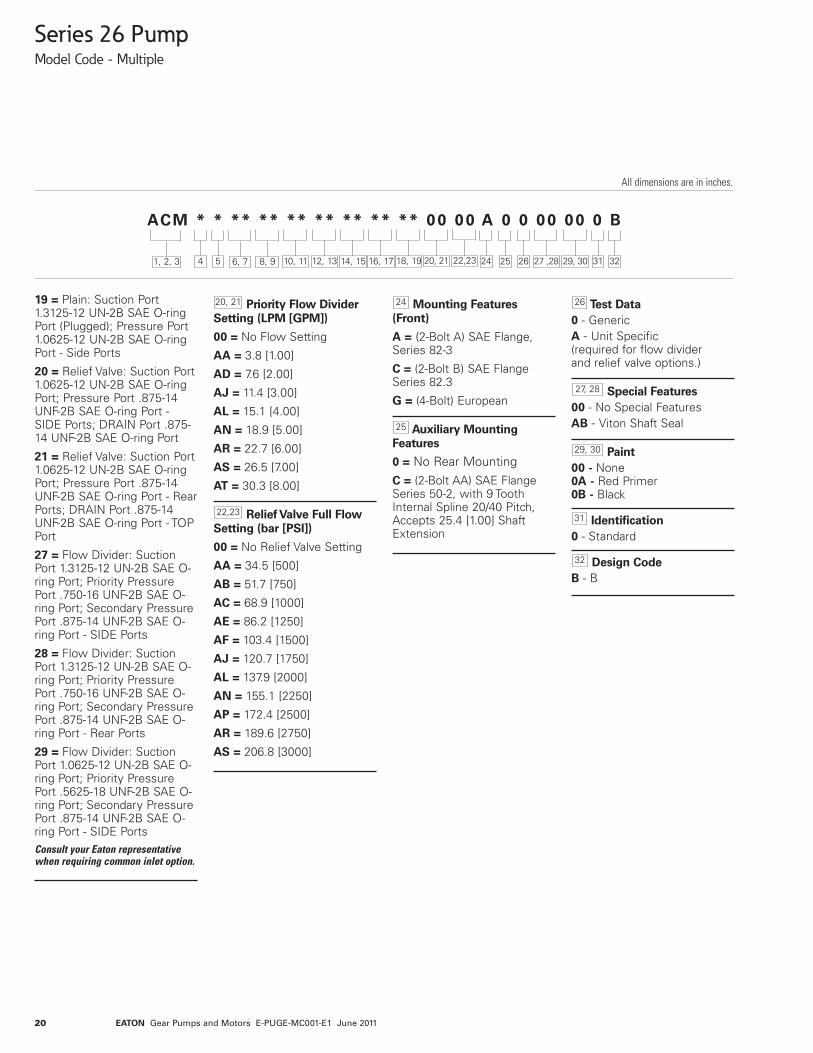
Series 26 PumpModel Code - Multiple
ACM * * ** ** ** ** ** ** ** 00 00 A 0 0 00 00 0 B
1, 2, 3 6, 7 8, 9 10, 114 5 24 323125 26
All dimensions are in inches.
26 SeriesACM – Gear Pump -
Multiple Unit
UnitTypeA – PlainB – Flow Divider with/without
Relief Valve (Pos. 20-21)C – Relief Valve
Input Rotation (viewedfrom input shaft end)L – Left-hand Rotation CCWR – Right-hand Rotation CW
Displacement - Front(cm3/r [in3/r])01 = 6.6 [.40]02 = 8.2 [.50]03 = 9.5 [.58]04 = 10.8 [.66]05 = 13.8 [.84]06 = 16.7 [1.02]07 = 19.7 [1.20]08 = 22.5 [1.37]09 = 24.3 [1.48]10 = 25.2 [1.54]11 = 27.7 [1.69]12 = 29.0 [1.77]13 = 30.6 [1.87]
Displacement - Ctr.Triple Only (cm3/r [in3/r])01 = 6.6 [.40]02 = 8.2 [.50]03 = 9.5 [.58]04 = 10.8 [.66]05 = 13.8 [.84]06 = 16.7 [1.02]07 = 19.7 [1.20]08 = 22.5 [1.37]09 = 24.3 [1.48]10 = 25.2 [1.54]11 = 27.7 [1.69]12 = 29.0 [1.77]13 = 30.6 [1.87]99 = No Center Displacement
Displacement - Rear(cm3/r [in3/r])01 = 6.6 [.40]02 = 8.2 [.50]03 = 9.5 [.58]04 = 10.8 [.66]05 = 13.8 [.84]06 = 16.7 [1.02]07 = 19.7 [1.20]08 = 22.5 [1.37]09 = 24.3 [1.48]10 = 25.2 [1.54]11 = 27.7 [1.69]12 = 29.0 [1.77]13 = 30.6 [1.87]
Input Shaft
AA = 5/8 Inch Dia. 9 ToothSpline 16/32 Pitch ShaftExtension 31.8 [1.25]
AB = 3/4 Inch Dia. 11 ToothSpline 16/32 Pitch ShaftExtension 31.8 [1.25]
AC = 3/4 Inch Dia. StraightKeyed, Keyway 4.8 x 25.4 [.19 x1.00] Shaft Extension 31.8 [1.25]
AD = 5/8 Inch Dia. StraightKeyed, Keyway 4.1 X 18.3 [.16 X.72] Shaft Extension 31.8 [1.25]
Front Adapter Ports
01 = Suction Port 1-5/8–12UN-2B SAE O-ring Port;Pressure Port 7/8–14 UNF-2BSAE O-ring Port
05 = Suction Port 1-5/16–12UN-2B SAE O-ring Port;Pressure Port 7/8–14 UNF-2BSAE O-ring Port
Ports - Rear Adapter(Triple Units)
00 = No Rear Adaptor
01 = Suction Port 1-5/8–12UN-2B SAE O-ring Port;Pressure Port 7/8–14 UNF-2BSAE O-ring Port
05 = Suction Port 1-5/16–12UN-2B SAE O-ring Port;Pressure Port 7/8–14 UNF-2BSAE O-ring Port
Ports, Sizes andLocation- Backplate
01 = Plain: Suction Port1-5/16–12 UN-2B SAE O-ringPort Size; Pressure Port7/8–14 UNF-2B SAE O-ringPort–Side Ports
02 = Plain: Suction Port1-5/16–12 UN-2B SAE O-ringPort Size; Pressure Port7/8–14 UNF-2B SAE O-ringPort–Rear Ports
03 = Plain: Suction Port1-1/16–12 UN-2B SAE O-ringPort Size; Pressure Port7/8–14 UNF-2B SAE O-ringPort–Side Ports
04 = Plain: Suction Port1-1/16–12 UN-2B SAE O-ringPort Size; Pressure Port7/8–14 UNF-2B SAE O-ringPort–Rear Ports
08 = Plain Tandem: SuctionPort 1.0625-12 UN-2B SAE O-ring Port; Pressure Port .875-14 UNF-2B SAE O-ring Port -Side Ports
14 = Plain: Suction Port1-5/16–12 UN-2B SAE O-ringPort Size–(Plugged); PressurePort 7/8–14 UNF-2B SAEO-ring Port–Side Ports, usedwith position 14 and 15–01and 16 and 17–10
17 = Plain: Suction Port1-5/16–12 UN-2B SAEO-ringPort Size–(Plugged);Pressure Port 7/8–14 UNF-2BSAE O-ring Port–Rear Ports,used with position 14 and15–01 and 16 and 17–01
18 = Plain Tandem: SuctionPort 1.0625-12 UN-2B SAE O-ring Port (Plugged); PressurePort .875-14 UNF-2B SAE O-ring Port - Side Ports
18, 19
16, 17
14, 1510, 11
8, 9
5
6, 712, 13
4
1, 2, 3
12, 13 14, 15 16, 17 18, 19 20, 21 22,23 27 ,28 29, 30
Series 26 Gear Pumps canbe ordered by using the fol-lowing Model Code.
A thirty-two digit coding sys-tem has been designed toidentify the featurespresently available onMultiple gear pumps.
The characters and their rela-tive positions within the codeidentify specific features.
Use the Model Code Matrixas an aid when assemblingthe model code for thepump with the features you
desire. It may be helpful tophotocopy the matrix andwrite the numbers and let-ters into the boxes as youselect features.
All thirty-two digits of thecode must be submittedwhen ordering.
EATON Gear Pumps and Motors E-PUGE-MC001-E1 June 2011
20
Series 26 PumpModel Code - Multiple
19 = Plain: Suction Port1.3125-12 UN-2B SAE O-ringPort (Plugged); Pressure Port1.0625-12 UN-2B SAE O-ringPort - Side Ports
20 = Relief Valve: Suction Port1.0625-12 UN-2B SAE O-ringPort; Pressure Port .875-14UNF-2B SAE O-ring Port -SIDE Ports; DRAIN Port .875-14 UNF-2B SAE O-ring Port
21 = Relief Valve: Suction Port1.0625-12 UN-2B SAE O-ringPort; Pressure Port .875-14UNF-2B SAE O-ring Port - RearPorts; DRAIN Port .875-14UNF-2B SAE O-ring Port - TOPPort
27 = Flow Divider: SuctionPort 1.3125-12 UN-2B SAE O-ring Port; Priority PressurePort .750-16 UNF-2B SAE O-ring Port; Secondary PressurePort .875-14 UNF-2B SAE O-ring Port - SIDE Ports
28 = Flow Divider: SuctionPort 1.3125-12 UN-2B SAE O-ring Port; Priority PressurePort .750-16 UNF-2B SAE O-ring Port; Secondary PressurePort .875-14 UNF-2B SAE O-ring Port - Rear Ports
29 = Flow Divider: SuctionPort 1.0625-12 UN-2B SAE O-ring Port; Priority PressurePort .5625-18 UNF-2B SAE O-ring Port; Secondary PressurePort .875-14 UNF-2B SAE O-ring Port - SIDE PortsConsult your Eaton representativewhen requiring common inlet option.
Priority Flow DividerSetting (LPM [GPM])
00 = No Flow Setting
AA = 3.8 [1.00]
AD = 7.6 [2.00]
AJ = 11.4 [3.00]
AL = 15.1 [4.00]
AN = 18.9 [5.00]
AR = 22.7 [6.00]
AS = 26.5 [7.00]
AT = 30.3 [8.00]
ReliefValve Full FlowSetting (bar [PSI])
00 = No Relief Valve Setting
AA = 34.5 [500]
AB = 51.7 [750]
AC = 68.9 [1000]
AE = 86.2 [1250]
AF = 103.4 [1500]
AJ = 120.7 [1750]
AL = 137.9 [2000]
AN = 155.1 [2250]
AP = 172.4 [2500]
AR = 189.6 [2750]
AS = 206.8 [3000]
Mounting Features(Front)
A = (2-Bolt A) SAE Flange,Series 82-3
C = (2-Bolt B) SAE FlangeSeries 82.3
G = (4-Bolt) European
Auxiliary MountingFeatures
0 = No Rear MountingC = (2-Bolt AA) SAE FlangeSeries 50-2, with 9 ToothInternal Spline 20/40 Pitch,Accepts 25.4 [1.00] ShaftExtension
Test Data0 - GenericA - Unit Specific(required for flow dividerand relief valve options.)
Special Features00 - No Special FeaturesAB - Viton Shaft Seal
Paint00 - None0A - Red Primer0B - Black
Identification0 - Standard
Design CodeB - B
20, 21
22,23
25
24
32
31
29, 30
26
27, 28
ACM * * ** ** ** ** ** ** ** 00 00 A 0 0 00 00 0 B
1, 2, 3 6, 7 8, 9 10, 114 5 24 323125 26
All dimensions are in inches.
12, 13 14, 15 16, 17 18, 19 20, 21 22,23 27 ,28 29, 30
EATON Gear Pumps and Motors E-PUGE-MC001-E1 June 2011

21
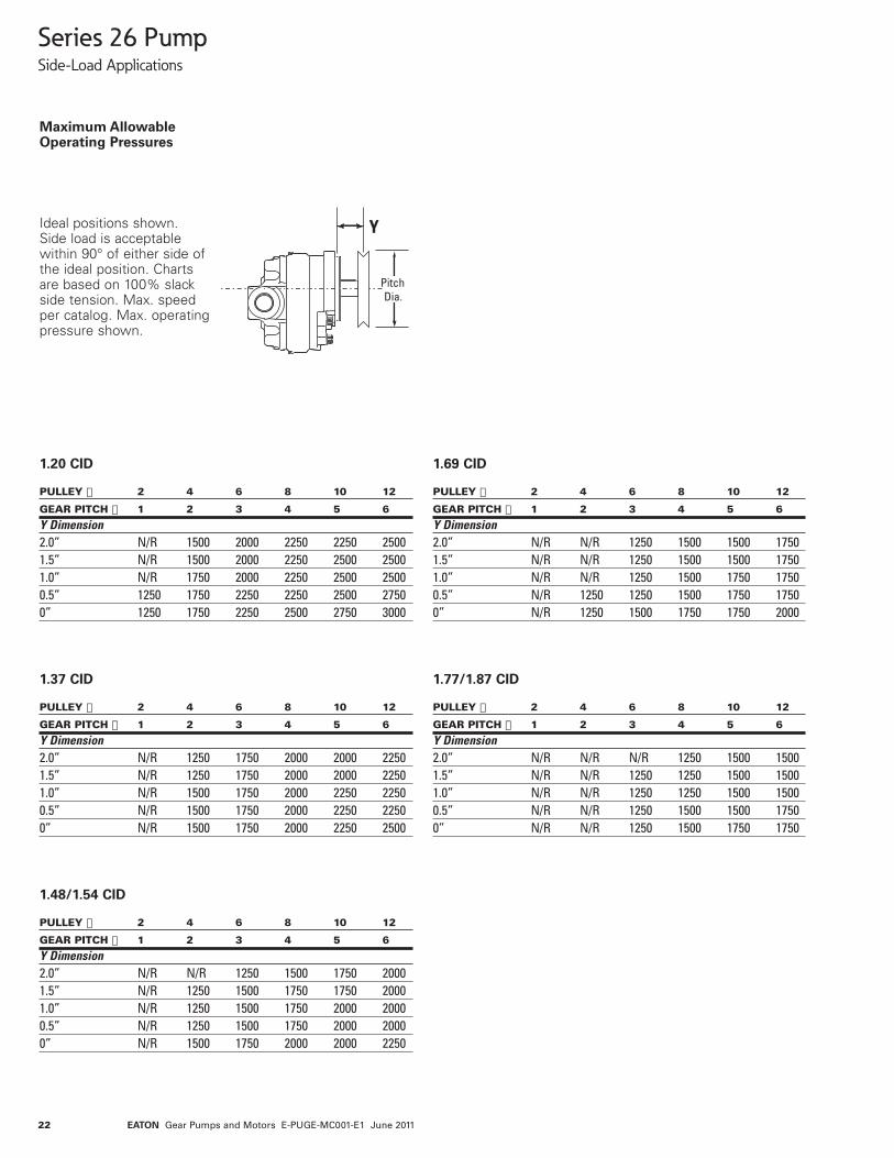
Series 26 PumpSide-Load Applications
MaximumAllowableOperating Pressures
0° Pump Inlet
0°
50°
0°45°
PumpInlet
PumpInlet
45°
50°
0°Pump Inlet
Y
PitchDia.
CW Rotation
CW Rotation
CCW Rotation
CCW Rotation
Ideal positions shown.Side load is acceptablewithin 90° of either side ofthe ideal position. Chartsare based on 100% slackside tension. Max. speedper catalog. Max. operatingpressure shown.
Gear Drive
Pulley Drive
PULLEY � 2 4 6 8 10 12
GEAR PITCH � 1 2 3 4 5 6
Y Dimension2.0” 3000 3000 3000 3000 3000 30001.5” 3000 3000 3000 3000 3000 30001.0” 3000 3000 3000 3000 3000 30000.5” 3000 3000 3000 3000 3000 30000” 3000 3000 3000 3000 3000 3000
0.40/0.50 CID
PULLEY � 2 4 6 8 10 12
GEAR PITCH � 1 2 3 4 5 6
Y Dimension2.0” 2250 3000 3000 3000 3000 30001.5” 2250 3000 3000 3000 3000 30001.0” 2500 3000 3000 3000 3000 30000.5” 2500 3000 3000 3000 3000 30000” 2750 3000 3000 3000 3000 3000
0.58/0.66 CID
PULLEY � 2 4 6 8 10 12
GEAR PITCH � 1 2 3 4 5 6
Y Dimension2.0” 1250 2000 2250 2500 2750 30001.5” 1250 2000 2500 2750 3000 30001.0” 1250 2000 2500 2750 3000 30000.5” 1500 2250 2500 2750 3000 30000” 1500 2250 2750 3000 3000 3000
1.02 CID
PULLEY � 2 4 6 8 10 12
GEAR PITCH � 1 2 3 4 5 6
Y Dimension2.0” 1750 2500 3000 3000 3000 30001.5” 1750 2750 3000 3000 3000 30001.0” 2000 2750 3000 3000 3000 30000.5” 2000 3000 3000 3000 3000 30000” 2250 3000 3000 3000 3000 3000
.84 CID
EATON Gear Pumps and Motors E-PUGE-MC001-E1 June 2011
22
Series 26 PumpSide-Load Applications
MaximumAllowableOperating Pressures
Y
PitchDia.
Ideal positions shown.Side load is acceptablewithin 90° of either side ofthe ideal position. Chartsare based on 100% slackside tension. Max. speedper catalog. Max. operatingpressure shown.
PULLEY � 2 4 6 8 10 12
GEAR PITCH � 1 2 3 4 5 6
Y Dimension2.0” N/R 1500 2000 2250 2250 25001.5” N/R 1500 2000 2250 2500 25001.0” N/R 1750 2000 2250 2500 25000.5” 1250 1750 2250 2250 2500 27500” 1250 1750 2250 2500 2750 3000
1.20 CID
PULLEY � 2 4 6 8 10 12
GEAR PITCH � 1 2 3 4 5 6
Y Dimension2.0” N/R 1250 1750 2000 2000 22501.5” N/R 1250 1750 2000 2000 22501.0” N/R 1500 1750 2000 2250 22500.5” N/R 1500 1750 2000 2250 22500” N/R 1500 1750 2000 2250 2500
1.37 CID
PULLEY � 2 4 6 8 10 12
GEAR PITCH � 1 2 3 4 5 6
Y Dimension2.0” N/R N/R 1250 1500 1500 17501.5” N/R N/R 1250 1500 1500 17501.0” N/R N/R 1250 1500 1750 17500.5” N/R 1250 1250 1500 1750 17500” N/R 1250 1500 1750 1750 2000
1.69 CID
PULLEY � 2 4 6 8 10 12
GEAR PITCH � 1 2 3 4 5 6
Y Dimension2.0” N/R N/R N/R 1250 1500 15001.5” N/R N/R 1250 1250 1500 15001.0” N/R N/R 1250 1250 1500 15000.5” N/R N/R 1250 1500 1500 17500” N/R N/R 1250 1500 1750 1750
1.77/1.87 CID
PULLEY � 2 4 6 8 10 12
GEAR PITCH � 1 2 3 4 5 6
Y Dimension2.0” N/R N/R 1250 1500 1750 20001.5” N/R 1250 1500 1750 1750 20001.0” N/R 1250 1500 1750 2000 20000.5” N/R 1250 1500 1750 2000 20000” N/R 1500 1750 2000 2000 2250
1.48/1.54 CID
EATON Gear Pumps and Motors E-PUGE-MC001-E1 June 2011

23
The Load SensingPriorityValve is used withthe open loop load sensesystemsthat are typicallyused in steering and brakingcircuits. The load sense gearpump provides metered pri-orityflow (CF)on demand.
The excess flow (EF)is avail-able for auxiliary circuits.Theresponse time was select-edto insure that the operatorwill not sense a delay orsteering “kick”during tran-sient conditions.
Series 26 PumpLoad Sensing Priority Valve
VALVE SPECIFICATIONS
Rated Pressure 207 BAR (3000PSI)Rated Inlet Flow 108 L/m (28GPM)Maximum Controlled Flow (CF) 33 L/m(8.5 GPM)Bias Pressure Dynamic - 10 bar (150 PSI) Std.
Static - 6.9 bar (100 PSI) Std.Relief Pressure 34.5-207 bar (500-3000 PSI)Response Time 70 msec. max. (std. bias spring)CF Flow Variation over full pressure range +/- 10%
PUMP SPECIFICATIONS
Displacements 9 Available: 8.2cm3/r [.50 in3/r] thru 30.6 cm3/r [1.87in3/r]Mounting SAE 2-Bolt A Mount
SAE 2-Bolt B Mount4-Bolt European Mount (80mm Pilot)
Ports Side or RearType Single or Multiple Configuration
EATON Gear Pumps and Motors E-PUGE-MC001-E1 June 2011

24
Series 26 MotorsGeneral Specifications
Displacement cm3/r [in3/r] 7,0 8,8 10,1 11,6 14,5 17,3 20,3[.43] [.54] [.62] [.71] [.88] [1.06] [1.24]
Max. Intermittent Pressure bar [PSI] 241 241 241 241 241 241 241[3495] [3495] [3495] [3495] [3495] [3495] [3495]
Rated Speed (RPM) 3600 3600 3600 3600 3600 3200 3200Minimum Output Flow at Continuous 22,2 27,9 32,0 36,7 48,0 50,9 59,8Rated Speed and Pressure LPM [GPM] [5.9] [7.4] [8.5] [9.7] [12.7] [13.5] [15.8]Input Power at Intermittent Rated 11,9 15,0 17,2 19,7 24,7 26,2 30,7Speed and Pressure kW [HP] [16.0] [20.1] [23.0] [26.5] [33.1] [35.1] [41.2]
Displacement cm3/r [in3/r] 23,1 25,2 26,0 28,8 30,3 31,7[1.41] [1.54] [1.59] [1.76] [1.85] [1.93]
Max. Intermittent Pressure bar [PSI] 241 241 241 241 234 224[3495] [3495] [3495] [3495] [3393] [3248]
Rated Speed (RPM) 3000 3000 3000 3000 3000 3000Minimum Output Flow at Continuous 63,8 69,6 71,8 79,5 83,6 87,5Rated Speed and Pressure LPM [GPM] [16.8] [18.4] [19.0] [21.0] [22.1] [23.1]Input Power at Intermittent Rated 32,8 35,7 36,9 40,8 41,7 41,8Speed and Pressure kW [HP] [43.9] [47.9] [49.4] [54.8] [55.9] [56.0]
The performance data in the table above and the following graphs was collected using a mineral base oil with a viscosity of 133 SUS at 49°C [120°F].
Rotation Bi-RotationMounting Flange SAE A 2 BoltMax. Continuous Pressure† 210 bar [3000 PSI]*Max. Intermittent Pressure†† 240 bar [3500 PSI]**Minimum Speed at Continuous Pressure 750 RPMMaximum Rotating Torque at 0 Pressure 4 Nm [36 lb-in]Maximum Continuous Operating Temperature 105°C [220°F]Minimum Continuous Oil Viscocity 5.7 cSt [45 SUS]Minimum Operating Temperature -29°C [-20°F]Maximum Inlet Vacuum at Operating Condition 0,8 bar Abs. [11.6 psi Abs.]Maximum Thrust Load 50 lbs.Maximum Seal Pressure 150 PSI, 200 PSI @ 1500 RPM
† Continuous - motor may be run continuously at these ratings.
†† Intermittent - intermittent operation, 10% of every minute.
* 31.8 cm3/rev. [1.94 in3/rev.] displacement max. continuous pressure is 190 bar [2750 PSI].
** 31.8 cm3/rev. [1.94 in3/rev.] displacement max. intermittent pressure is 224 bar [3250 PSI].
For side load limits consult your Eaton representative.
Ordering Information
Catalog Assemblies CrossReference
Standard catalog assemblies arebuilt from high production partsand are the most economicalpump assemblies available in thisseries. The standard assembly
order number is a preassignedpart number and may be used toorder the specific standardassembly (see page 24).
EATON Gear Pumps and Motors E-PUGE-MC001-E1 June 2011
25
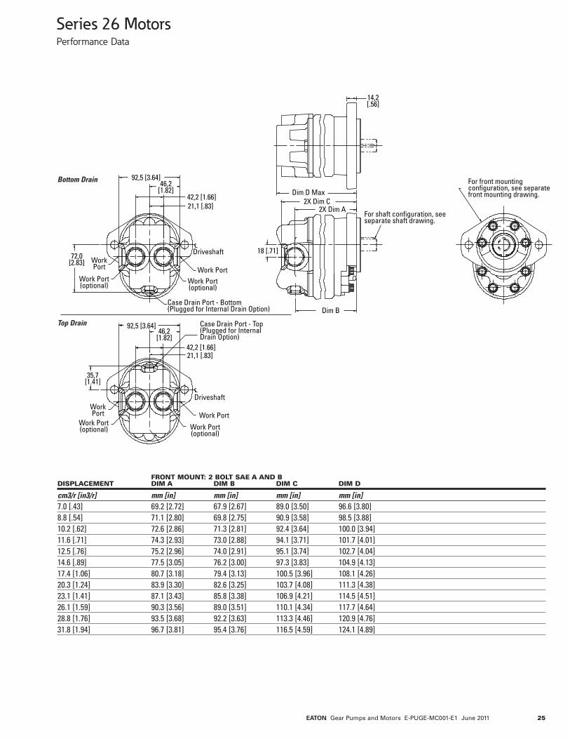
Series 26 MotorsPerformance Data
92,5 [3.64]46,2
[1.82]
21,1 [.83]
Driveshaft
42,2 [1.66]
Work PortWork Port(optional)
Case Drain Port - Bottom(Plugged for Internal Drain Option)
WorkPort
Work Port(optional)
72,0[2.83]
WorkPort
Work Port(optional)
35,7[1.41]
Case Drain Port - Top(Plugged for Internal Drain Option)
Driveshaft
Work Port
Work Port(optional)
92,5 [3.64]46,2
[1.82]
21,1 [.83]42,2 [1.66]
18 [.71]
Dim D Max2X Dim C
2X Dim A
14,2[.56]
For shaft configuration, seeseparate shaft drawing.
For front mounting configuration, see separate front mounting drawing.
Dim B
Bottom Drain
Top Drain
FRONT MOUNT: 2 BOLT SAE A AND BDISPLACEMENT DIM A DIM B DIM C DIM D
cm3/r [in3/r] mm [in] mm [in] mm [in] mm [in]7.0 [.43] 69.2 [2.72] 67.9 [2.67] 89.0 [3.50] 96.6 [3.80]8.8 [.54] 71.1 [2.80] 69.8 [2.75] 90.9 [3.58] 98.5 [3.88]10.2 [.62] 72.6 [2.86] 71.3 [2.81] 92.4 [3.64] 100.0 [3.94]11.6 [.71] 74.3 [2.93] 73.0 [2.88] 94.1 [3.71] 101.7 [4.01]12.5 [.76] 75.2 [2.96] 74.0 [2.91] 95.1 [3.74] 102.7 [4.04]14.6 [.89] 77.5 [3.05] 76.2 [3.00] 97.3 [3.83] 104.9 [4.13]17.4 [1.06] 80.7 [3.18] 79.4 [3.13] 100.5 [3.96] 108.1 [4.26]20.3 [1.24] 83.9 [3.30] 82.6 [3.25] 103.7 [4.08] 111.3 [4.38]23.1 [1.41] 87.1 [3.43] 85.8 [3.38] 106.9 [4.21] 114.5 [4.51]26.1 [1.59] 90.3 [3.56] 89.0 [3.51] 110.1 [4.34] 117.7 [4.64]28.8 [1.76] 93.5 [3.68] 92.2 [3.63] 113.3 [4.46] 120.9 [4.76]31.8 [1.94] 96.7 [3.81] 95.4 [3.76] 116.5 [4.59] 124.1 [4.89]
EATON Gear Pumps and Motors E-PUGE-MC001-E1 June 2011

26
Series 26 MotorsModel Code - Single
ADM * * ** ** A 00 00 0 00 0 00 00 0 A
1, 2, 3 6, 7 8, 94 5 18 242310 15
All dimensions are in inches.
26 SeriesADM – Gear Motor
UnitTypeA – Plain
Output RotationD – Bi-DirectionalL – Left-hand Rotation CCWR – Right-hand Rotation CW
Displacement(cm3/r [in3/r])01 = 7.0 [.43]02 = 8.8 [.54]03 = 10.2 [.62]04 = 11.6 [.71]05 = 14.6 [.89]06 = 17.4 [1.06]07 = 20.3 [1.24]08 = 23.1 [1.41]09 = 25.2 [1.54]10 = 26.1 [1.59]11 = 28.8 [1.76]12 = 30.3 [1.85]13 = 31.8 [1.94]
Output Shaft
AA = 9 Tooth Spline 16/32Spline, Min. Full Spline 22.4[.88], Shaft Extension 31.8[1.25]
AB = 11 Tooth Spline 16/32Spline, Min. Full Spline 22.4[.88], Shaft Extension 31.8[1.25]
AC = Straight Shaft Dia 19.05[.750], Keyway 4.8 x 25.4 [.19x 1.00], Shaft Extension 31.8[1.25] (Key Included)
AD = Straight Shaft Dia 15.88[.625], Keyway 4.1 x 18.3 [.16x .72], Shaft Extension 31.8[1.25] (Key Included)
AJ = Dia 15.88 [.625], Taper.125:1, .500-20 UNF-2A,Keyway 4.1 x 17.5 [.16 x .69],Shaft Extension 43.7 [1.72](Key Included)
Mounting Features
A = 2-Bolt A - SAE FlangeSeries 82-2
Ports, Sizes andLocation- Backplate
01 = Inlet Port 1.0625-12UN-2B SAE O-Ring Port;Outlet Port 1.0625-12 UN-2BSAE O-Ring Port - Side Ports
02 = Inlet Port 1.0625-12UN-2B SAE O-Ring Port;Outlet Port 1.0625-12 UN-2BSAE O-Ring Port - Rear Ports
03 = Inlet Port .875-14UN-2B SAE O-Ring Port;Outlet Port .875-14 UN-2BSAE O-Ring Port - Side Ports
04 = Inlet Port .875-14UN-2B SAE O-Ring Port;Outlet Port .875-14 UN-2BSAE O-Ring Port - Rear Ports
Case Drain
00 = No Case Drain
AA = .5625-18 UNF-2B SAEO-Ring Port - Bottom
AB = .5625-18 UNF-2B SAEO-Ring Port - Top
AC = Internal withBi-Directional Checks,.5625-18 UNF-2B SAEO-Ring Port - Plugged
AD = .5625-18 UNF-2B SAEO-Ring Port - Bottom-Plugged
AE = .5625-18 UNF-2B SAEO-Ring Port - Top-Plugged
ReliefValveType
0 = No Relief Valve
C = Cross-over
ReliefValve Settingbar [lbf/in2]
00 = No Relief Valve Setting
AA = 117.2 [1700]
AB = 141.3 [2050]
AC = 31.0 [450]
Test Data0 - GenericA - Unit Specific(Used with Relief Valve)
Special Features00 - No Special Features
Paint00 - None0A - Primer per Spec 209-13A0B - Black per Spec 209-13B
Identification0 - Standard
Design CodeA - A
1024
23
21, 22
18
16, 17
5
6, 7
19, 20
15
13, 14
11, 128, 9
4
1, 2, 3
11, 12 13, 14 16, 17 19, 20 21, 22
Series 26 Gear Motors canbe ordered by using the fol-lowing Model Code.
A twenty-four digit codingsystem has been designedto identify the featurespresently available on singlegear pumps. The charactersand their relative positions
within the code identify spe-cific features.
Use the Model Code Matrixas an aid when assemblingthe model code for thepump with the features youdesire. It may be helpful tophotocopy the matrix and
write the numbers and let-ters into the boxes as youselect features.
All twenty-four digits of thecode must be submittedwhen ordering.
EATON Gear Pumps and Motors E-PUGE-MC001-E1 June 2011


![New York Tribune.(New York, NY) 1875-01-28 [p 6].chroniclingamerica.loc.gov/lccn/sn83030214/1875-01-28/ed-1/seq-6.pdf · I»itIDE-ID Nurai L.ttmiK Puge 1st column, i.i.](https://img.pdfslide.us/doc/110x75/5b51cf547f8b9ad8118c6c45/new-york-tribunenew-york-ny-1875-01-28-p-6-iitide-id-nurai-lttmik.jpg)