Embed Size (px)
Citation preview
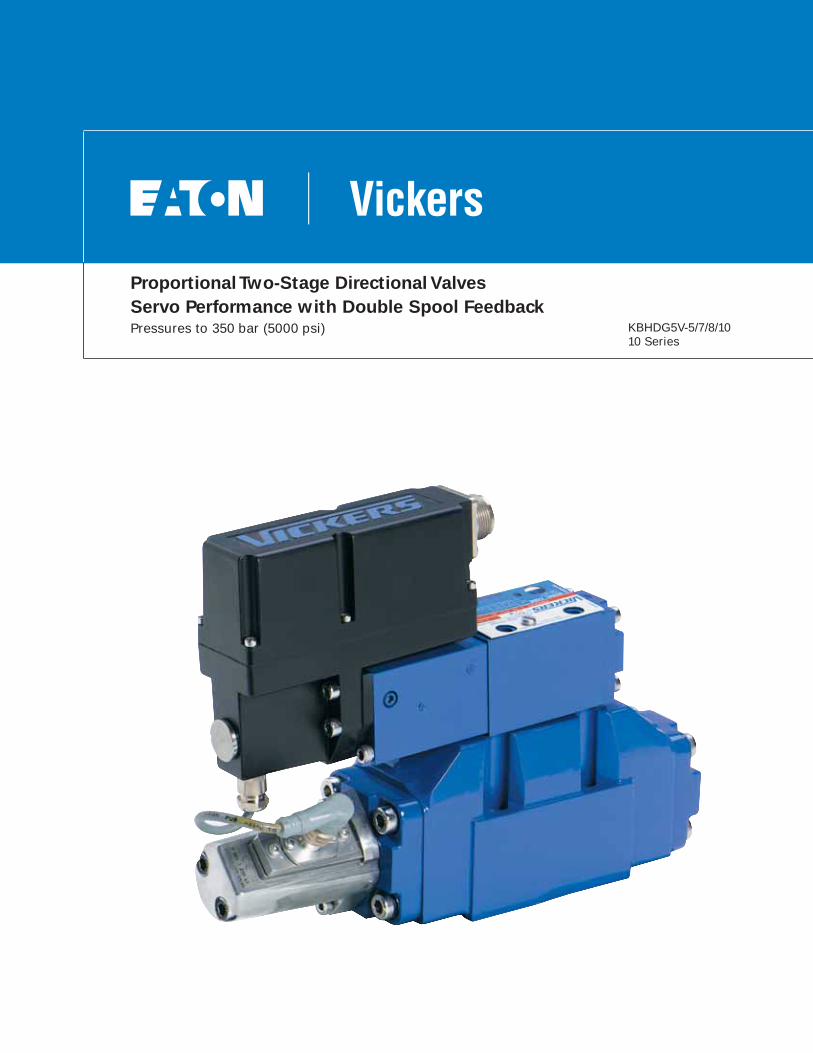
Proportional Two-Stage Directional Valves
Servo Performance with Double Spool FeedbackPressures to 350 bar (5000 psi) KBHDG5V-5/7/8/10
10 Series
2 EATON Vickers Proportional Two-Stage Directional Valves V-VLDI-MC001-E1 March 2007
Contents
Introduction
General Description 3
Features and Benefits 3
Typical Section 3
Model Code 4
Spool Data 5
Functional Symbol 5
Operating Data 6
Pressures and Minimum Flow Rates 7
Performance Curves
Power Capacity Envelope 8
Pressure Gain 8
Frequency Response 8
Flow Gain 9
Dimension KBHDG5V-5/7/8/10 12
Mounting Surface Interface KBHDG5V-5/7/8/10 14
Electrical Information
Block Diagram 16
Typical Connection Arrangements 17
Application Data
Fluid Cleanliness 18
Hydraulic Fluids 18
Installation 18
Mounting Bolt Kits 18
Seal Kits 18
Electrical Connectors 18
Extension Cable 18
Service Information 18
Released Model Codes 19
3EATON Vickers Proportional Two-Stage Directional Valves V-VLDI-MC001-E1 March 2007
Introduction
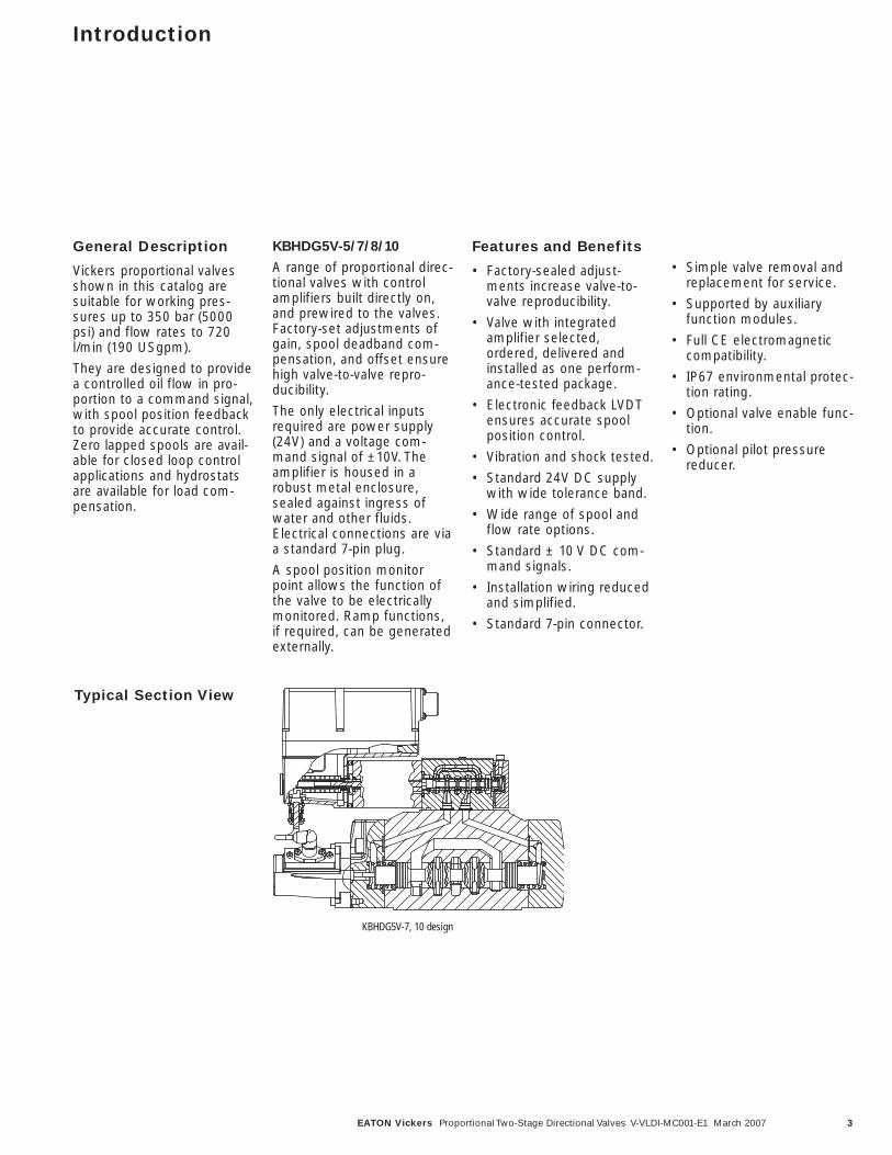
General Description
Vickers proportional valvesshown in this catalog aresuitable for working pres-sures up to 350 bar (5000psi) and flow rates to 720l/min (190 USgpm).
They are designed to providea controlled oil flow in pro-portion to a command signal,with spool position feedbackto provide accurate control.Zero lapped spools are avail-able for closed loop controlapplications and hydrostatsare available for load com-pensation.
KBHDG5V-5/7/8/10
A range of proportional direc-tional valves with controlamplifiers built directly on,and prewired to the valves.Factory-set adjustments ofgain, spool deadband com-pensation, and offset ensurehigh valve-to-valve repro-ducibility.
The only electrical inputsrequired are power supply(24V) and a voltage com-mand signal of ±10V. Theamplifier is housed in arobust metal enclosure,sealed against ingress ofwater and other fluids.Electrical connections are viaa standard 7-pin plug.
A spool position monitorpoint allows the function ofthe valve to be electricallymonitored. Ramp functions,if required, can be generatedexternally.
Features and Benefits
• Factory-sealed adjust-ments increase valve-to-valve reproducibility.
• Valve with integratedamplifier selected,ordered, delivered andinstalled as one perform-ance-tested package.
• Electronic feedback LVDTensures accurate spoolposition control.
• Vibration and shock tested.
• Standard 24V DC supplywith wide tolerance band.
• Wide range of spool andflow rate options.
• Standard ± 10 V DC com-mand signals.
• Installation wiring reducedand simplified.
• Standard 7-pin connector.
• Simple valve removal andreplacement for service.
• Supported by auxiliaryfunction modules.
• Full CE electromagneticcompatibility.
• IP67 environmental protec-tion rating.
• Optional valve enable func-tion.
• Optional pilot pressurereducer.
Typical Section View
KBHDG5V-7, 10 design
4 EATON Vickers Proportional Two-Stage Directional Valves V-VLDI-MC001-E1 March 2007
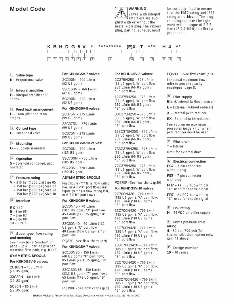
Model Code
Valve type
K – Proportional valve
Integral amplifier
B – Integral amplifier “B”series
Feed back arrangement
H – From pilot and mainstages
Control type
D - Directional valve
Mounting
G – Subplate mounted
Operation
5 – Solenoid controlled, pilotoperated
Pressure rating
V – 310 bar (4500 psi) Size 05– 350 bar (5000 psi) Size 07– 350 bar (5000 psi) Size 08– 350 bar (5000 psi) Size 10
Interface
ISO 44015 – Size 057 – Size 078 – Size 0810 – Size 10
Spool type, flow rating
and metering
See “Functional Symbol” onpage 5. p = 5 bar (72 psi) permetering flow path, e.g. B to T.
SYMMETRIC SPOOLS
For KBHDG5V-5 valves:
2C100N – 100 L/min (26 US gpm)
33C80N – 80 L/min (21 US gpm)
5C85N – 85 L/min (22 US gpm)
For KBHDG5V-7 valves:
2C200N – 200 L/min (52 US gpm)
33C160N – 160 L/min (42 US gpm)
5C200N – 200 L/min (52 US gpm)
For KBHDG5V-8 valves:
2C375N – 375 L/min (99 US gpm)
33C375N – 375 L/min (99 US gpm)
5C375N – 375 L/min (99 US gpm)
For KBHDG5V-10 valves:
2C700N – 700 L/min (185 US gpm)
33C700N – 700 L/min (185 US gpm)
5C720N – 720 L/min (190 US gpm)
ASYMMETRIC SPOOLS
First figure (***N) is flow ratingP-A, or A-T (“A” port flow); lastfigure (N***) is flow rating P-B,or B-T (“B” port flow)
For KBHDG5V-5 valves:
2C70N45 – 70 L/min (18.5 US gpm), “A” port flow45 L/min (11.9 US gpm), “B”port flow
33C60N40 – 60 L/min (17.2US gpm), “A” port flow 40 L/min (10.6 US gpm), “B”port flow
PQ87F - See flow charts (p.9)
For KBHDG5V-7 valves:
2C150N85 – 150 L/min (40 US gpm), “A” port flow; 85 L/min (22.4 US gpm), “B”port flow
33C130N65 – 130 L/min (33.3 US gpm), “A” port flow;65 L/min (17.2 US gpm), “B”port flow
PQ190F - See flow charts (p.9)
For KBHDG5V-8 valves:
2C375N250 – 375 L/min (99 US gpm), “A” port flow; 250 L/min (66 US gpm), “B” port flow
12C375N250 – 375 L/min (99 US gpm), “A” port flow; 250 L/min (66 US gpm), “B” port flow
33C375N250 – 375 L/min (99 US gpm), “A” port flow; 250 L/min (66 US gpm), “B” port flow
133C375N250 – 375 L/min (99 US gpm), “A” port flow; 250 L/min (66 US gpm), “B” port flow
733C375N250 – 375 L/min (99 US gpm), “A” port flow; 250 L/min (66 US gpm), “B” port flow
72C375N250 – 375 L/min (99 US gpm), “A” port flow; 250 L/min (66 US gpm), “B” port flow
PQ375F - See flow charts (p.10)
For KBHDG5V-10 valves:
2C700N420 – 700 L/min (185 US gpm), “A” port flow; 420 L/min (110 US gpm), “B” port flow
33C700N420 – 700 L/min (185 US gpm), “A” port flow; 420 L/min (110 US gpm), “B” port flow
12C700N420 – 700 L/min (185 US gpm), “A” port flow; 420 L/min (110 US gpm), “B” port flow
133C700N420 – 700 L/min (185 US gpm), “A” port flow; 420 L/min (110 US gpm), “B” port flow
72C700N420 – 700 L/min (185 US gpm), “A” port flow; 420 L/min (110 US gpm), “B” port flow
733C700N420 – 700 L/min (185 US gpm), “A” port flow; 420 L/min (110 US gpm), “B” port flow
PQ680 F - See flow charts (p.11)
For actual maximum flowsrefer to power capacityenvelopes, page 8.
Pilot supply
Blank–Internal (without reducer)
E – External (without reducer)
X – Internal (with reducer)
EX– External (with reducer)
See section on maximumpressures (page 7) for whenpilot reducer must be used.
Pilot drain
T – Internal
Omit for external drain
Electrical connection
PC7 – 7 pin connector without plug
PE7 – 7 pin connector with plug
PH7 – As PE7 but with pin“C” used for enable signal
PR7 – As PC7 but with pin“C” used for enable signal
Coil rating
H – 24 VDC amplifier supply
Port T pressure limit
rating
4 – 50 bar (700 psi) (forinternal pilot drain option only,item 11 above)
Design number
10 – 10 series
15
14
13
12
11
10
9
8
7
6
5
4
3
2
1
K B H D G 5 V – * – ********* – (E)X – T – *** – H 4 – **
1 2 3 4 5 6 7 8 10 11 12 13 14 159
WARNING
Valves with integralamplifiers are sup-
plied with or without themetal 7-pin plug. The Vickersplug, part no. 934939, must
be correctly fitted to ensurethat the EMC rating and IP67rating are achieved. The plugretaining nut must be tight-ened with a torque of 2-2,5Nm (1.5-2.0 lbf ft) to effect aproper seal.
•
5EATON Vickers Proportional Two-Stage Directional Valves V-VLDI-MC001-E1 March 2007
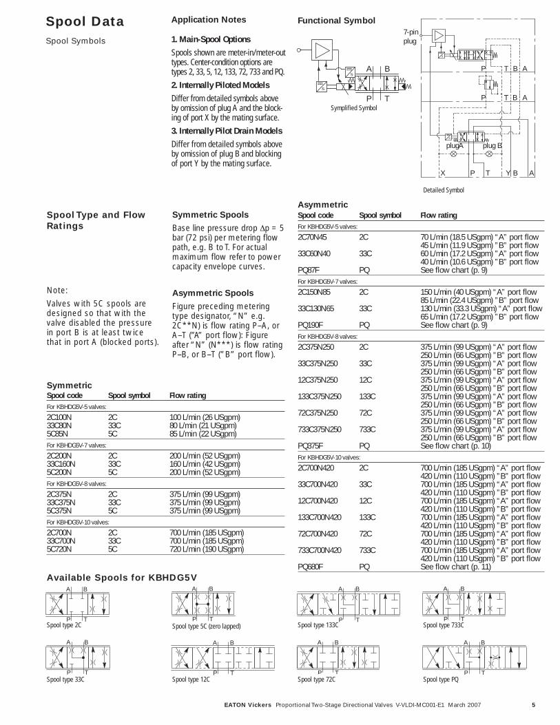
Spool DataSpool Symbols
Spool code Spool symbol Flow ratingFor KBHDG5V-5 valves:
2C100N 2C 100 L/min (26 USgpm)33C80N 33C 80 L/min (21 USgpm)5C85N 5C 85 L/min (22 USgpm)For KBHDG5V-7 valves:
2C200N 2C 200 L/min (52 USgpm)33C160N 33C 160 L/min (42 USgpm)5C200N 5C 200 L/min (52 USgpm)For KBHDG5V-8 valves:
2C375N 2C 375 L/min (99 USgpm)33C375N 33C 375 L/min (99 USgpm)5C375N 5C 375 L/min (99 USgpm)For KBHDG5V-10 valves:
2C700N 2C 700 L/min (185 USgpm)33C700N 33C 700 L/min (185 USgpm)5C720N 5C 720 L/min (190 USgpm)
Spool code Spool symbol Flow ratingFor KBHDG5V-5 valves:
2C70N45 2C 70 L/min (18.5 USgpm) “A” port flow45 L/min (11.9 USgpm) ”B” port flow
33C60N40 33C 60 L/min (17.2 USgpm) ”A” port flow40 L/min (10.6 USgpm) ”B” port flow
PQ87F PQ See flow chart (p. 9)For KBHDG5V-7 valves:
2C150N85 2C 150 L/min (40 USgpm) “A” port flow85 L/min (22.4 USgpm) ”B” port flow
33C130N65 33C 130 L/min (33.3 USgpm) “A” port flow65 L/min (17.2 USgpm) ”B” port flow
PQ190F PQ See flow chart (p. 9)For KBHDG5V-8 valves:
2C375N250 2C 375 L/min (99 USgpm) “A” port flow250 L/min (66 USgpm) ”B” port flow
33C375N250 33C 375 L/min (99 USgpm) “A” port flow250 L/min (66 USgpm) ”B” port flow
12C375N250 12C 375 L/min (99 USgpm) “A” port flow250 L/min (66 USgpm) ”B” port flow
133C375N250 133C 375 L/min (99 USgpm) “A” port flow250 L/min (66 USgpm) ”B” port flow
72C375N250 72C 375 L/min (99 USgpm) “A” port flow250 L/min (66 USgpm) ”B” port flow
733C375N250 733C 375 L/min (99 USgpm) “A” port flow250 L/min (66 USgpm) ”B” port flow
PQ375F PQ See flow chart (p. 10)For KBHDG5V-10 valves:
2C700N420 2C 700 L/min (185 USgpm) “A” port flow420 L/min (110 USgpm) ”B” port flow
33C700N420 33C 700 L/min (185 USgpm) “A” port flow420 L/min (110 USgpm) ”B” port flow
12C700N420 12C 700 L/min (185 USgpm) “A” port flow420 L/min (110 USgpm) ”B” port flow
133C700N420 133C 700 L/min (185 USgpm) “A” port flow420 L/min (110 USgpm) ”B” port flow
72C700N420 72C 700 L/min (185 USgpm) “A” port flow420 L/min (110 USgpm) ”B” port flow
733C700N420 733C 700 L/min (185 USgpm) “A” port flow420 L/min (110 USgpm) ”B” port flow
PQ680F PQ See flow chart (p. 11)
Spool Type and FlowRatings
Symmetric Spools
Base line pressure drop Δp = 5bar (72 psi) per metering flowpath, e.g. B to T. For actualmaximum flow refer to powercapacity envelope curves.
Asymmetric Spools
Figure preceding meteringtype designator, “N” e.g.2C**N) is flow rating P–A, orA–T (”A” port flow): Figureafter “N” (N***) is flow ratingP–B, or B–T (”B” port flow).
Note:
Valves with 5C spools aredesigned so that with thevalve disabled the pressurein port B is at least twicethat in port A (blocked ports).
Available Spools for KBHDG5VA B
P TSpool type 2C
A B
P TSpool type 33C
A B
P TSpool type 5C (zero lapped)
A B
P TSpool type 72C
A B
P TSpool type 733C
A B
P TSpool type 133C
A B
P TSpool type 12C
Application Notes
1. Main-Spool Options
Spools shown are meter-in/meter-outtypes. Center-condition options aretypes 2, 33, 5, 12, 133, 72, 733 and PQ.
2. Internally Piloted Models
Differ from detailed symbols aboveby omission of plug A and the block-ing of port X by the mating surface.
3. Internally Pilot Drain Models
Differ from detailed symbols aboveby omission of plug B and blockingof port Y by the mating surface.
A
T
B
P
Functional Symbol
7-pinplug
AT BP
ATX BYP
AT BP
plug A plug B
Detailed Symbol
Symplified Symbol
A B
P TSpool type PQ
Symmetric
Asymmetric
6 EATON Vickers Proportional Two-Stage Directional Valves V-VLDI-MC001-E1 March 2007
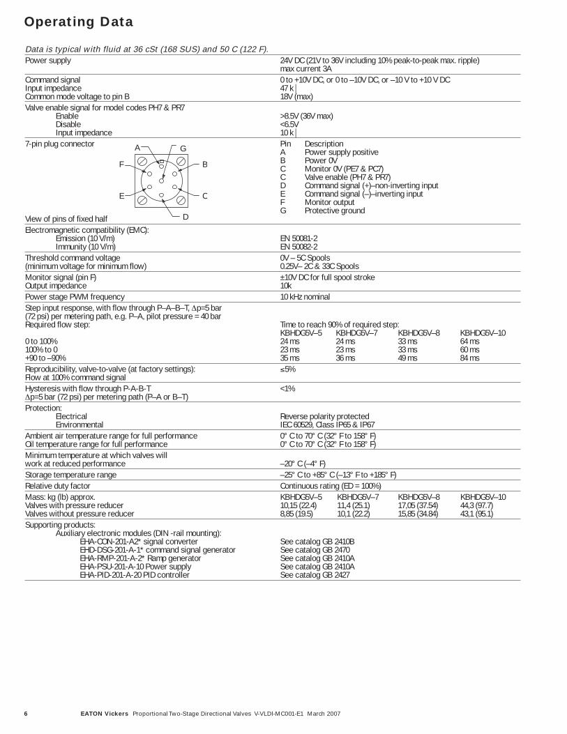
Operating Data
Data is typical with fluid at 36 cSt (168 SUS) and 50 C (122 F).Power supply 24V DC (21V to 36V including 10% peak-to-peak max. ripple)
max current 3ACommand signal 0 to +10V DC, or 0 to –10V DC, or –10 V to +10 V DCInput impedance 47 k⏐Common mode voltage to pin B 18V (max)Valve enable signal for model codes PH7 & PR7
Enable >8.5V (36V max)Disable <6.5VInput impedance 10 k⏐
7-pin plug connector Pin DescriptionA Power supply positiveB Power 0VC Monitor 0V (PE7 & PC7)C Valve enable (PH7 & PR7)D Command signal (+)–non-inverting inputE Command signal (–)–inverting inputF Monitor outputG Protective ground
View of pins of fixed halfElectromagnetic compatibility (EMC):
Emission (10 V/m) EN 50081-2Immunity (10 V/m) EN 50082-2
Threshold command voltage 0V – 5C Spools(minimum voltage for minimum flow) 0.25V– 2C & 33C SpoolsMonitor signal (pin F) ±10V DC for full spool strokeOutput impedance 10kPower stage PWM frequency 10 kHz nominalStep input response, with flow through P–A–B–T, Δp=5 bar (72 psi) per metering path, e.g. P–A, pilot pressure = 40 bar Required flow step: Time to reach 90% of required step:
KBHDG5V–5 KBHDG5V–7 KBHDG5V–8 KBHDG5V–100 to 100% 24 ms 24 ms 33 ms 64 ms100% to 0 23 ms 23 ms 33 ms 60 ms+90 to –90% 35 ms 36 ms 49 ms 84 msReproducibility, valve-to-valve (at factory settings): ≤5%Flow at 100% command signalHysteresis with flow through P-A-B-T <1%Δp=5 bar (72 psi) per metering path (P–A or B–T)Protection:
Electrical Reverse polarity protectedEnvironmental IEC 60529, Class IP65 & IP67
Ambient air temperature range for full performance 0° C to 70° C (32° F to 158° F)Oil temperature range for full performance 0° C to 70° C (32° F to 158° F)Minimum temperature at which valves will work at reduced performance –20° C (–4° F)Storage temperature range –25° C to +85° C (–13° F to +185° F)Relative duty factor Continuous rating (ED = 100%)Mass: kg (lb) approx. KBHDG5V–5 KBHDG5V–7 KBHDG5V–8 KBHDG5V–10 Valves with pressure reducer 10,15 (22.4) 11,4 (25.1) 17,05 (37.54) 44,3 (97.7) Valves without pressure reducer 8,85 (19.5) 10,1 (22.2) 15,85 (34.84) 43,1 (95.1) Supporting products:
Auxiliary electronic modules (DIN -rail mounting):EHA-CON-201-A2* signal converter See catalog GB 2410BEHD-DSG-201-A-1* command signal generator See catalog GB 2470EHA-RMP-201-A-2* Ramp generator See catalog GB 2410AEHA-PSU-201-A-10 Power supply See catalog GB 2410AEHA-PID-201-A-20 PID controller See catalog GB 2427
F
A G
B
C
D
E
7EATON Vickers Proportional Two-Stage Directional Valves V-VLDI-MC001-E1 March 2007
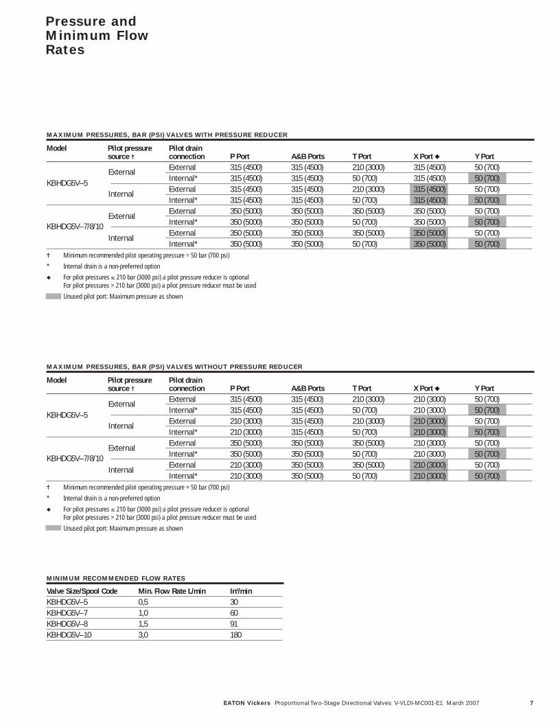
Model Pilot pressure Pilot drainsource ✝ connection P Port A&B Ports T Port X Port ◆ Y Port
External 315 (4500) 315 (4500) 210 (3000) 315 (4500) 50 (700) Internal* 315 (4500) 315 (4500) 50 (700) 315 (4500) 50 (700) External 315 (4500) 315 (4500) 210 (3000) 315 (4500) 50 (700) Internal* 315 (4500) 315 (4500) 50 (700) 315 (4500) 50 (700) External 350 (5000) 350 (5000) 350 (5000) 350 (5000) 50 (700) Internal* 350 (5000) 350 (5000) 50 (700) 350 (5000) 50 (700) External 350 (5000) 350 (5000) 350 (5000) 350 (5000) 50 (700) Internal* 350 (5000) 350 (5000) 50 (700) 350 (5000) 50 (700)
✝ Minimum recommended pilot operating pressure = 50 bar (700 psi)
* Internal drain is a non-preferred option
◆ For pilot pressures ≤ 210 bar (3000 psi) a pilot pressure reducer is optional For pilot pressures > 210 bar (3000 psi) a pilot pressure reducer must be used
Unused pilot port: Maximum pressure as shown
KBHDG5V–5
KBHDG5V–7/8/10
Pressure andMinimum FlowRates
MAXIMUM PRESSURES, BAR (PSI) VALVES WITH PRESSURE REDUCER
External
Internal
External
Internal
Model Pilot pressure Pilot drainsource ✝ connection P Port A&B Ports T Port X Port ◆ Y Port
External 315 (4500) 315 (4500) 210 (3000) 210 (3000) 50 (700) Internal* 315 (4500) 315 (4500) 50 (700) 210 (3000) 50 (700) External 210 (3000) 315 (4500) 210 (3000) 210 (3000) 50 (700) Internal* 210 (3000) 315 (4500) 50 (700) 210 (3000) 50 (700) External 350 (5000) 350 (5000) 350 (5000) 210 (3000) 50 (700) Internal* 350 (5000) 350 (5000) 50 (700) 210 (3000) 50 (700) External 210 (3000) 350 (5000) 350 (5000) 210 (3000) 50 (700) Internal* 210 (3000) 350 (5000) 50 (700) 210 (3000) 50 (700)
✝ Minimum recommended pilot operating pressure = 50 bar (700 psi)
* Internal drain is a non-preferred option
◆ For pilot pressures ≤ 210 bar (3000 psi) a pilot pressure reducer is optional For pilot pressures > 210 bar (3000 psi) a pilot pressure reducer must be used
Unused pilot port: Maximum pressure as shown
KBHDG5V–5
KBHDG5V–7/8/10
MAXIMUM PRESSURES, BAR (PSI) VALVES WITHOUT PRESSURE REDUCER
External
Internal
External
Internal
Valve Size/Spool Code Min. Flow Rate L/min In3/minKBHDG5V–5 0,5 30 KBHDG5V–7 1,0 60 KBHDG5V–8 1,5 91KBHDG5V–10 3,0 180
MINIMUM RECOMMENDED FLOW RATES
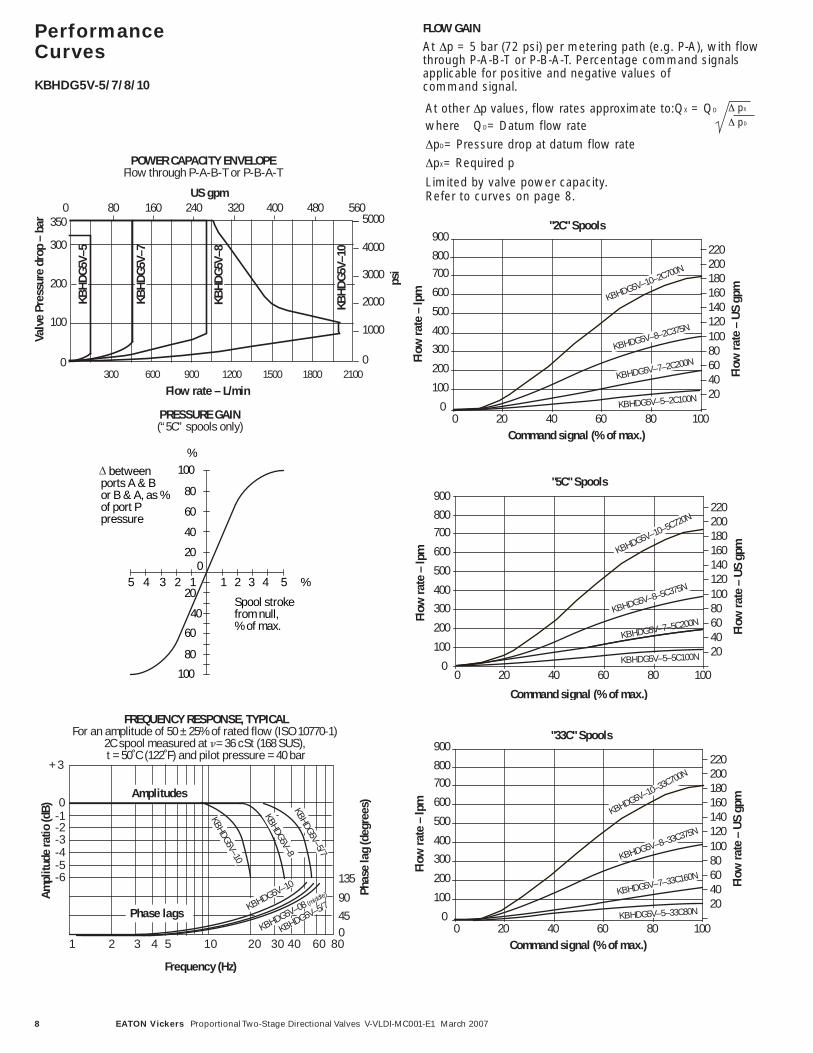
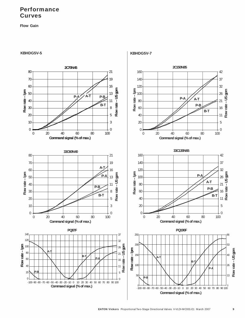
FLOW GAIN
At Δp = 5 bar (72 psi) per metering path (e.g. P-A), with flowthrough P-A-B-T or P-B-A-T. Percentage command signalsapplicable for positive and negative values of command signal.
"2C" Spools
Flow
rate
– lp
m
Flow
rate
– U
S gp
m
Command signal (% of max.)0 20 40 60 80 100
KBHDG5V–5–2C100N
KBHDG5V–7–2C200N
KBHDG5V–8–2C375N
20406080100120140160180200220
0
100
200
300400
500
600
700
900
800
KBHDG5V–10–2C700N
At other Δp values, flow rates approximate to:QX = QD
where QD= Datum flow rateΔpD= Pressure drop at datum flow rateΔpX= Required p
Limited by valve power capacity. Refer to curves on page 8.
Δ pX
Δ pD
"5C" Spools
Flow
rate
– lp
m
Flow
rate
– U
S gp
m
Command signal (% of max.)
0 20 40 60 80 100 KBHDG5V–5–5C100N
KBHDG5V–7–5C200NKBHDG5V–8–5C375N
20406080100120140160180200220
0
100
200
300400
500
600
700
900
800
KBHDG5V–10–5C720N
"33C" Spools
Flow
rate
– lp
m
Flow
rate
– U
S gp
m
Command signal (% of max.)0 20 40 60 80 100
20406080100120140160180200220
0
100
200
300400
500
600
700
900
800
KBHDG5V–10–33C700N
KBHDG5V–5–33C80N
KBHDG5V–7–33C160N
KBHDG5V–8–33C375N
8 EATON Vickers Proportional Two-Stage Directional Valves V-VLDI-MC001-E1 March 2007
PerformanceCurves
KBHDG5V-5/7/8/10
350
300
200
100
0
Flow rate – L/min 300 600 900 1200 1500 1800 2100
POWER CAPACITY ENVELOPEFlow through P-A-B-T or P-B-A-T
US gpm160 240 320800 400 480
5000
4000
3000
2000
1000
psi
0
Valv
e Pr
essu
re d
rop
– ba
r
560
KBH
DG
5V–7
KBH
DG
5V–5
KBH
DG
5V–8
KBH
DG
5V–1
0
Spool strokefrom null,% of max.
1 2 3 4 5 %12345
40
60
80
100%
20
40
60
80
100
20
0
PRESSURE GAIN(“5C” spools only)
betweenports A & Bor B & A, as %of port Ppressure
1 2 3 4 5 1 0 2 0 3 0 4 0 6 0 8 0
Amplitudes
Phase lags
Frequency (Hz)
+ 3
0-1-2-3-4-5-6
Ampl
itude
ratio
(dB)
Phas
e la
g (d
egre
es)
135
90
045
KBHDG5V–8KBHDG5V–5/7
KBHDG5V–5/7KBHDG5V–10
FREQUENCY RESPONSE, TYPICALFor an amplitude of 50 ± 25% of rated flow (ISO 10770-1)
2C spool measured at �= 36 cSt (168 SUS), t = 50˚C (122˚F) and pilot pressure = 40 bar
KBHDG5V–10
KBHDG5V–08 (middle)
9EATON Vickers Proportional Two-Stage Directional Valves V-VLDI-MC001-E1 March 2007
33C60N40
Flow
rate
– lp
m
Flow
rate
– U
S gp
m
Command signal (% of max.)
0
10
20
30
40
50
60
70
80
0 2 0 4 0 6 0 8 0 100 0
3
5
8
11
13
16
19
21
P-B
A-T
B-T
P-A
2C150N85
Flow
rate
– lp
m
Flow
rate
– U
S gp
m
Command signal (% of max.)
0
20
40
60
80
100
120
140
160
0 2 0 4 0 6 0 8 0 100 0
5
11
16
21
26
32
37
42
P-B
A-T
B-T
P-A
PerformanceCurves
Flow Gain
33C130N65
Flow
rate
– lp
m
Flow
rate
– U
S gp
mCommand signal (% of max.)
0
20
40
60
80
100
120
140
160
0 2 0 4 0 6 0 8 0 100 0
5
11
16
21
26
32
37
42
P-B
A-T
B-T
P-A
Flow
rate
– lp
m
Flow
rate
– U
S gp
m
Command signal (% of max.)
0
10
20
30
40
50
60
70
80
0 2 0 4 0 6 0 8 0 100
2C70N45
0
3
5
8
11
13
16
19
21
P-BA-T
B-T
P-A
KBHDG5V-7KBHDG5V-5
PQ87F
0
20
40
60
80
100
120
140
-100 -90 -80 -70 -60 -50 -40 -30 -20 -10 0 10 20 30 40 50 60 70 80 90 100Command signal (% of max.)
A-T
P-B
B-TP-A
Flow
rate
– lp
m
0
5
11
16
21
26
32
37
Flow
rate
– U
S gp
m
PQ190F
0
50
100
150
200
-100 -90 -80 -70 -60 -50 -40 -30 -20 -10 0 10 20 30 40 50 60 70 80 90 100
Command signal (% of max.)
A-T
P-B
B-T
P-AFlow
rate
– lp
m
250Fl
ow ra
te –
US
gpm
0
13
26
40
53
66
10 EATON Vickers Proportional Two-Stage Directional Valves V-VLDI-MC001-E1 March 2007
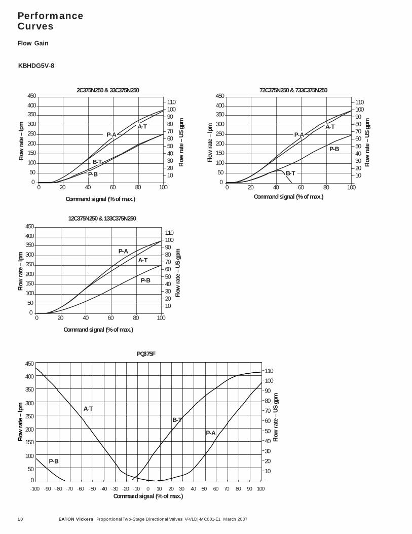
72C375N250 & 733C375N250
Flow
rate
– lp
m
Flow
rate
– U
S gp
m
Command signal (% of max.)
0
50
100
150200
250
300
350
450
400
0 20 40 60 80 100
102030405060708090100110
P-B
A-T
B-T
P-A
PerformanceCurves
Flow Gain
12C375N250 & 133C375N250
Flow
rate
– lp
m
Flow
rate
– U
S gp
m
Command signal (% of max.)
0
50
100
150200
250
300
350
450
400
0 20 40 60 80 100
102030405060708090100110
P-B
A-TP-A
2C375N250 & 33C375N250
Flow
rate
– lp
m
Flow
rate
– U
S gp
m
Command signal (% of max.)
0
50
100
150200
250
300
350
450
400
0 20 40 60 80 100
102030405060708090100110
P-B
A-T
B-T
P-A
PQ375F
0
50
100
150
200
250
300
350
450
400
-100 -90 -80 -70 -60 -50 -40 -30 -20 -10 0 10 20 30 40 50 60 70 80 90 100Command signal (% of max.)
A-T
P-B
B-T
P-A
Flow
rate
– lp
m
Flow
rate
– U
S gp
m
10
20
30
40
50
60
70
80
90
100
110
KBHDG5V-8
11EATON Vickers Proportional Two-Stage Directional Valves V-VLDI-MC001-E1 March 2007
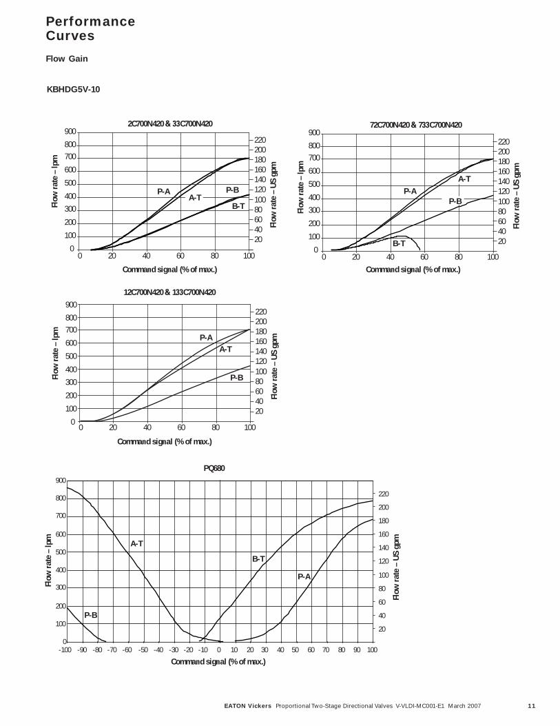
72C700N420 & 733C700N420
Flow
rate
– U
S gp
m
0
100
200
300400
500
600
700
900
800
0 20 40 60 80 100
2C700N420 & 33C700N420
Flow
rate
– U
S gp
m
0
100
200
300400
500
600
700
900
800
0 20 40 60 80 100
PQ680
0
100
200
300
400
500
600
700
900
800
-100 -90 -80 -70 -60 -50 -40 -30 -20 -10 0 10 20 30 40 50 60 70 80 90 100
12C700N420 & 133C700N420
Flow
rate
– U
S gp
m
Command signal (% of max.)
0 20 40 60 80 100
20406080100120140160180200220
Command signal (% of max.)
A-T
P-B
B-T
P-A
P-A P-AA-T
A-TP-B
P-BB-T
B-T
P-AA-T
P-B
Flow
rate
– lp
m
Flow
rate
– U
S gp
m
Flow
rate
– lp
m
Flow
rate
– lp
m
Flow
rate
– lp
m
0
100
200
300400
500
600
700
900
800
20406080100120140160180200220
20406080100120140160180200220
20
40
60
80
100
120
140
160
180
200
220
Command signal (% of max.) Command signal (% of max.)
PerformanceCurves
Flow Gain
KBHDG5V-10
12 EATON Vickers Proportional Two-Stage Directional Valves V-VLDI-MC001-E1 March 2007
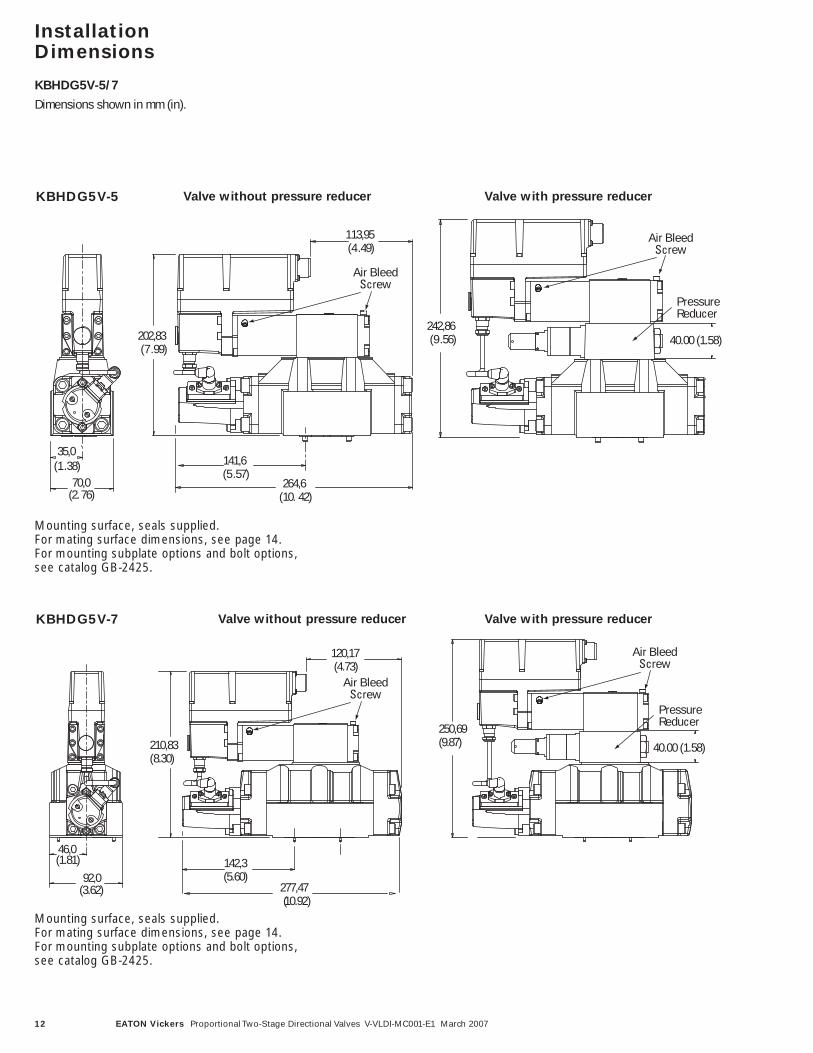
InstallationDimensions
KBHDG5V-5/7
Dimensions shown in mm (in).
Mounting surface, seals supplied. For mating surface dimensions, see page 14. For mounting subplate options and bolt options, see catalog GB-2425.
KBHDG5V-5 Valve without pressure reducer Valve with pressure reducer
Valve without pressure reducer Valve with pressure reducerKBHDG5V-7
35,0( 1 . 38)
70,0(2. 76)
264,6( 10. 42)
1 13,95 ( 4 . 49)
202,83( 7 . 99)
242,86( 9 . 56)
141,6( 5 . 57)
Air Bleed Screw
Air Bleed Screw
PressureReducer
40.00 (1.58)
142,3(5.60)
46,0(1.81)
92,0(3.62)
120,17(4.73)
277,47 (10.92)
250,69(9.87)210,83
( 8.30)
Air Bleed Screw
Air Bleed Screw
PressureReducer
40.00 (1.58)
Mounting surface, seals supplied. For mating surface dimensions, see page 14. For mounting subplate options and bolt options, see catalog GB-2425.
13EATON Vickers Proportional Two-Stage Directional Valves V-VLDI-MC001-E1 March 2007
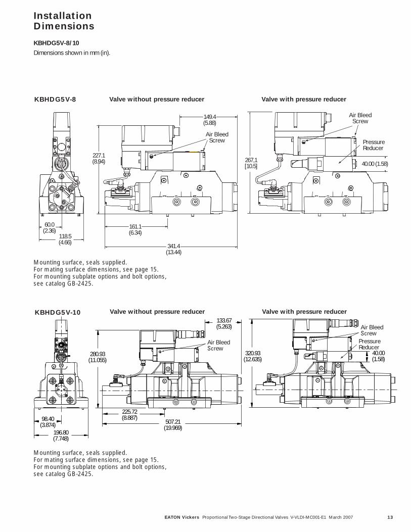
InstallationDimensions
KBHDG5V-8/10
Dimensions shown in mm (in).
KBHDG5V-8
267,1[10.5]
Pressure Reducer
40.00 (1.58)
Air BleedScrew
60.0(2.36)
118.5(4.66)
227.1(8.94)
161.1(6.34)
341.4(13.44)
149.4(5.88)
Air BleedScrew
Mounting surface, seals supplied.For mating surface dimensions, see page 15. For mounting subplate options and bolt options, see catalog GB-2425.
Mounting surface, seals supplied.For mating surface dimensions, see page 15. For mounting subplate options and bolt options, see catalog GB-2425.
98.40(3.874)
196.80(7.748)
280.93(11.055)
507.21(19.969)
133.67(5.263)
Air BleedScrew
320.93(12.635)
40.00(1.58)
Air BleedScrew
Pressure Reducer
225.72(8.887)
KBHDG5V-10
Valve without pressure reducer Valve with pressure reducer
Valve without pressure reducer Valve with pressure reducer
14 EATON Vickers Proportional Two-Stage Directional Valves V-VLDI-MC001-E1 March 2007
2 holes Ø 4,0 (0.157 dia)x 8,0 (0.31) min. depth
4 holes M10 x 17,0 (0.67)min. full thread depth
2 holes M6-6H x 17,0 (0.67)min. full thread depth
3 holes (ports L, X, Y)Ø 6,3 (0.25 dia) max. 4 holes (ports P, T, A, B)
Ø 17,5 (0.69 dia) max.
95,0(3.74) min.
130,0 (5.12) min.
18,3(0.72)
34,1 (1.34)
50,0 (1.97)
65,9 (2.59)
76,6 (3.016)
88,1 (3.47)101,6 ± 0,1 (4.0 ± 0.004)
1,6 ± 0,1(0.063 ± 0.004)
14,3 (0.56)
15,9(0.63)
71,5± 0,1(2.815
± 0.004)
PT
A B
X
Y
L
11,0(0.43)
69,9± 0,1(2.75
± 0.004)
57,2(2.25)
55,6(2.19)
34,9(1.38)
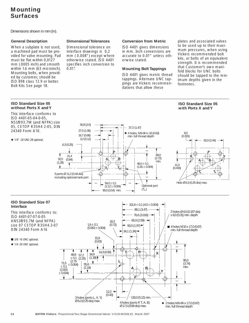
MountingSurfaces
Dimensions shown in mm (in).
General Description
When a subplate is not used,a machined pad must be pro-vided for valve mounting. Padmust be flat within 0,0127mm (.0005 inch) and smoothwithin 1.6 mm (63 microinch).Mounting bolts, when provid-ed by customer, should beISO 898 class 12.9 or better.Bolt Kits See page 18.
Dimensional Tolerances
Dimensional tolerance oninterface drawings is 0,2mm ( 0.008”) except whereotherwise stated. ISO 4401specifies inch conversion to0.01”.
Conversion from Metric
ISO 4401 gives dimensionsin mm. Inch conversions areaccurate to 0.01” unless oth-erwise stated.
Mounting Bolt Tappings
ISO 4401 gives metric threadtappings. Alternate UNC tap-pings are Vickers recommen-dations that allow these
plates and associated valvesto be used up to their maxi-mum pressures, when usingVickers recommended boltkits, or bolts of an equivalentstrength. It is recommendedthat Customer’s own mani-fold blocks for UNC boltsshould be tapped to the min-imum depths given in thefootnotes.
ISO Standard Size 05 without Ports X and Y
This interface conforms toISO 4401-05-04-0-05,NSI/B93.7M (and NFPA) size05, CETOP R35H4 2-05, DIN24340 Form A10.
ISO Standard Size 05 with Ports X and Y
37,3 (1.47)
5 ports Ø 11,2 (0.44 dia)including optional tank port
27,0 (1.06)16,7 (0.66)
6,3 (0.25)
3,2 (0.12)
50,8 (2.0)
46,0 ± 0,1(1.81 ± 0.004)
32,5(1.28)
90,0 (3.54) min.
P
A B
TA TB
54,0 ± 0,1(2.12 ± 0.004)
69,0(2.72)min.
21,4(0.84)
Optional port (TB )
4 holes, M6-6H x 16 (0.63)min. full thread depth
P
A
TA TB
62,0 (2.44)
8,0(0.315)
11,0(0.433)
X
Hole Ø 6,3 (0.25 dia) max.
YB
ISO Standard Size 07Interface
This interface conforms to:ISO 4401-07-07-0-05ANSI/B93.7M (and NFPA)size 07 CETOP R35H4.3-07DIN 24340 Form A16
■ 3/8 -16 UNC optional.
◆ 1/4 -20 UNC optional.
■
◆
◆ 1/4” -20 UNC-2B optional.
◆
15EATON Vickers Proportional Two-Stage Directional Valves V-VLDI-MC001-E1 March 2007
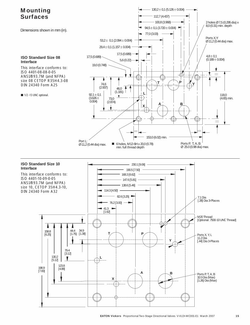
MountingSurfaces
Dimensions shown in mm (in).
ISO Standard Size 08Interface
This interface conforms to:ISO 4401-08-08-0-05ANSI/B93.7M (and NFPA)size 08 CETOP R35H4.3-08DIN 24340 Form A25
■ 1/2 -13 UNC optional.
2 holes Ø 7,5 (0.295 dia) x8,0 (0.31) min. depth
6 holes, M12-6H x 20,0 (0.78)min. full thread depth
153,0 (6.02) min.
5,6 (0.22)
17,5 (0.689)
29,4 ± 0,1 (1.157 ± 0.004)
53,2 ± 0,1 (2.094 ± 0.004)
94,5 ± 0,1 (3.720 ± 0.004)
100,8 (3.968)
112,7 (4.437)
130,2 ± 0,1 (5.126 ± 0.004)
77,0 (3.03)
92,1 ± 0,1(3.626 ± 0.004)
74,6(2.937)
73,0(2.874)
46,0(1.181)
19,0 (0.748)
17,5 (0.689)
118,0 (4.65) min.
4,8 ± 0,1(0.189 ± 0.004)
Ports X,Y:Ø 11,2 (0.44 dia) max.
Port L:Ø 11,2 (0.44 dia) max. Ports P, T, A, B:
Ø 25.0 (0.98 dia) max.
PT
AX
Y
L
B
34.9 [1.38]
41.3[1.62]
76.2 [3.00]
82.6 [3.25]
114.3 [4.50]
138.6 [5.46]
147.6 [5.81]
168.3 [6.62]190.5 [7.50]
230.1 [9.06]
44.4[1.75]
79.4[3.12]
123.8[4.88]
130.2[5.12]
158.8[6.25]
198.9[7.83]
7.1 Dia [.28] Dia 3-Places
Ports X, Y, L11.2 Dia[.44] Dia 3-Places
Ports P, T, A, B32.0 Dia (Max)[1.26] Dia (Max)
T P
Y
A B
X
L
M20 Thread[Optional .7500-10 UNC Thread]
■
ISO Standard Size 10Interface
This interface conforms to:ISO 4401-10-09-0-05ANSI/B93.7M (and NFPA)size 10, CETOP 35H4.3-10,DIN 24340 Form A32
16 EATON Vickers Proportional Two-Stage Directional Valves V-VLDI-MC001-E1 March 2007
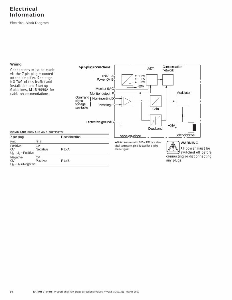
ElectricalInformationElectrical Block Diagram
Modulator
Solenoid driveValve envelope
7-pin plug connections
+24V AB
D
E
F
G
Power 0V
Monitor 0V
Protective ground
Non-inverting
Inverting
Commandsignalvoltage,see table
Compensationnetwork
+15V0V
- 15V+24V
LVDT
CMonitor output
+24V
Gain
Deadband
Wiring
Connections must be madevia the 7-pin plug mountedon the amplifier. See pageNO TAG of this leaflet andInstallation and Start-upGuidelines, ML-B-9090A forcable recommendations.
COMMAND SIGNALS AND OUTPUTS
7-pin plug Flow direction Pin D Pin E
Positive OVP to AOV Negative
UD - UE = PositiveNegative OV
P to BOV PositiveUD - UE = Negative
WARNING
All power must beswitched off before
connecting or disconnectingany plugs.
▲Note: In valves with PH7 or PR7 type elec-trical connection, pin C is used for a valveenable signal. •
17EATON Vickers Proportional Two-Stage Directional Valves V-VLDI-MC001-E1 March 2007
Input
User Panel
Power Supply
Demand Signal
SpoolPosition Monitor
0V must be connected to ground
Enclosure
+24V0V
+/-10VValve must be connected toground viasubplate
Connector shell
Outer Screen KB..PC7/PE7 valve
A
B
D or E0V
0V
C
Drain Wire
Inner Screen
G
F
ElectricalInformationTypical Connection
Arrangements
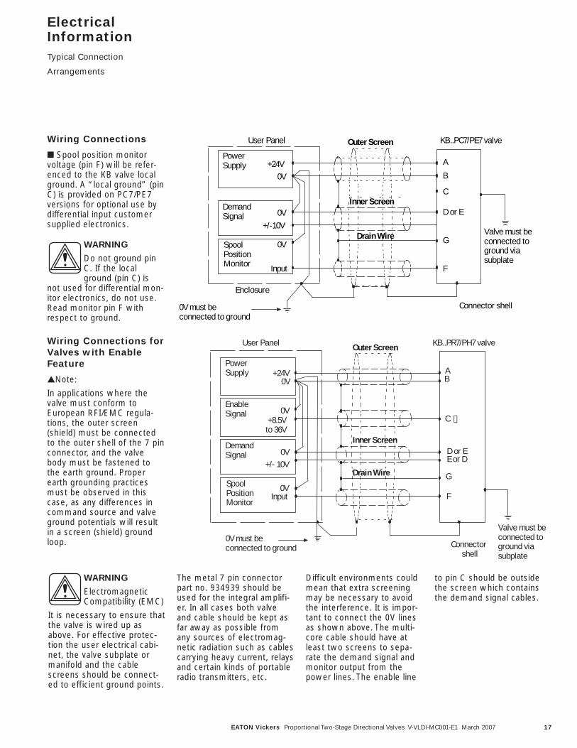
Wiring Connections
■ Spool position monitorvoltage (pin F) will be refer-enced to the KB valve localground. A “local ground” (pinC) is provided on PC7/PE7versions for optional use bydifferential input customersupplied electronics.
WARNING
Do not ground pinC. If the localground (pin C) is
not used for differential mon-itor electronics, do not use.Read monitor pin F withrespect to ground.
0V
I nput
User Panel
Power Supply
Demand Signal
Spool Position Monitor
+24V
+/- 10V
V alve must be connected to ground via subplate
Connector shell
Outer Screen
A B
D or E
0V
0V
C ✟
Drain Wire
Inner Screen
E or D
G
F
KB..PR7/PH7 valve
0V must be connected to ground
Enable Signal
+8.5V to 36V
0V
Wiring Connections forValves with EnableFeature
▲Note:
In applications where thevalve must conform toEuropean RFI/EMC regula-tions, the outer screen(shield) must be connectedto the outer shell of the 7 pinconnector, and the valvebody must be fastened tothe earth ground. Properearth grounding practicesmust be observed in thiscase, as any differences incommand source and valveground potentials will resultin a screen (shield) groundloop.
WARNING
ElectromagneticCompatibility (EMC)
It is necessary to ensure thatthe valve is wired up asabove. For effective protec-tion the user electrical cabi-net, the valve subplate ormanifold and the cablescreens should be connect-ed to efficient ground points.
The metal 7 pin connectorpart no. 934939 should beused for the integral amplifi-er. In all cases both valveand cable should be kept asfar away as possible fromany sources of electromag-netic radiation such as cablescarrying heavy current, relaysand certain kinds of portableradio transmitters, etc.
Difficult environments couldmean that extra screeningmay be necessary to avoidthe interference. It is impor-tant to connect the 0V linesas shown above. The multi-core cable should have atleast two screens to sepa-rate the demand signal andmonitor output from thepower lines. The enable line
to pin C should be outsidethe screen which containsthe demand signal cables.•
•
18 EATON Vickers Proportional Two-Stage Directional Valves V-VLDI-MC001-E1 March 2007
ApplicationData
Fluid Cleanliness
Proper fluid condition isessential for long and satis-factory life of hydraulic com-ponents and systems.Hydraulic fluid must have thecorrect balance of cleanli-ness, materials and additivesfor protection against wearof components, elevated vis-cosity and inclusion of air.
Recommendations on con-tamination control methodsand the selection of productsto control fluid condition areincluded in Vickers publica-tion 9132 or 561, “VickersGuide to SystemicContamination Control”. Thebook also includes informa-tion on the Vickers conceptof “ProActive Maintenance”.The following recommenda-tions are based on ISOcleanliness levels at 2 µm, 5 µm and 15 µm
For products in this catalogthe recommended levels are:
0 to 70 bar (1000 psi) –18/16/13
70 + bar (1000 + psi) –17/15/12
Vickers products, as anycomponents, will operatewith apparent satisfaction influids with higher cleanlinesscodes than those described.Other manufacturers willoften recommend levelsabove those specified.
Experience has shown, how-ever, that life of any hydrauliccomponents is shortened influids with higher cleanlinesscodes than those listedabove. These codes havebeen proven to provide along trouble-free service lifefor the products shown,regardless of the manufac-turer.
Hydraulic Fluids
Materials and seals used inthese valves are compatiblewith antiwear hydraulic oils,and non-alkyl-based phos-phate esters. The extremeoperating viscosity range is500 to 13 cSt (2270 to 70SUS) but the recommendedrunning range is 54 to 13 cSt(245 to 70 SUS). For furthertechnical information aboutfluids see “TechnicalInformation” leaflet B-920 orI-286S.
Installation
The proportional valves inthis catalog can be mountedin any attitude, but it may benecessary in certaindemanding applications, toensure that the solenoids arekept full of hydraulic fluid.Good installation practice dic-tates that the tank port andany drain port are piped soas to keep the valves full offluid once the system start-up has been completed.
Mounting Bolt Kits
For KBHDG5V-5
BKDG01633M (metric) -#466310
BKDG01633 (inch) - #255633
For KBHDG5V-7
BKDG7 858918 (metric) -#858918
BK590724 (inch) - #590724
For KBHDG5V-8
BKDG8-655M (metric) -#255655
BKDG06-635 (inch) -#255635
For KBHDG5V-10
BKDG10-636M (metric) -#466321
BKDG10-636 (inch) - #255636
If not using Vickers recom-mended bolt kits, boltsused should be to ISO 898,12.9 or better.
Seal Kits
KBHDG5V-5 ..........02-350518
KBHDG5V-7 ..........02-350519
KBHDG5V-8 ..........02-350686
KBHDG5V-10.........02-411687
Electrical Connectors
KBHDG5V
7-pin plug (metal).......934939
7-pin plug (plastic)......694534
(metal plug must be used forfull EMC protection)
Note:
An alternative metal connec-tor which gives EMC protec-tion but not IP67 rating isavailable from ITT-Cannon,part number CA06-COM-E-14S-A7-S.
Extension Cable
Extension Cable: Adapter forextending 7 core cable whenchanging from KA to KBvalve and existing wiring isnot long enough. Consists ofa 7 pin plug, a 7 pin socketand a length of cable, fullyassembled for ease of useExtension Cable.........944450
Service Information
The products from this rangeare preset at the factory foroptimum performance; disas-sembling critical items woulddestroy these settings. It istherefore recommended thatshould any mechanical orelectronic repair be neces-sary they should be returnedto the nearest Vickers repaircenter. The products will berefurbished as necessary andretested to specificationbefore return.
Field repair is restricted tothe replacement of the seals.
Note:
The feedback/solenoidassembly installed in thisvalve should not be disas-sembled.
19EATON Vickers Proportional Two-Stage Directional Valves V-VLDI-MC001-E1 March 2007
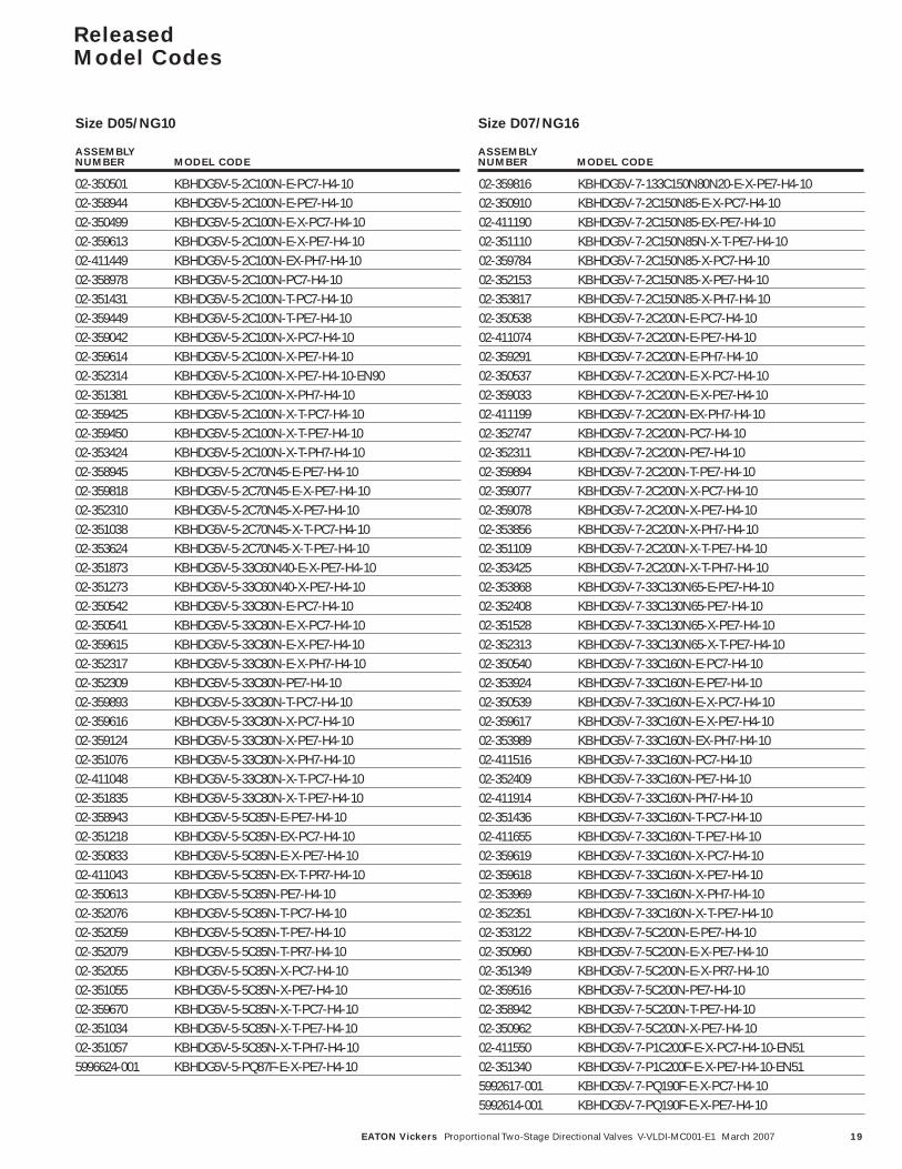
Released Model Codes
02-350501 KBHDG5V-5-2C100N-E-PC7-H4-1002-358944 KBHDG5V-5-2C100N-E-PE7-H4-1002-350499 KBHDG5V-5-2C100N-E-X-PC7-H4-1002-359613 KBHDG5V-5-2C100N-E-X-PE7-H4-1002-411449 KBHDG5V-5-2C100N-EX-PH7-H4-1002-358978 KBHDG5V-5-2C100N-PC7-H4-1002-351431 KBHDG5V-5-2C100N-T-PC7-H4-1002-359449 KBHDG5V-5-2C100N-T-PE7-H4-1002-359042 KBHDG5V-5-2C100N-X-PC7-H4-1002-359614 KBHDG5V-5-2C100N-X-PE7-H4-1002-352314 KBHDG5V-5-2C100N-X-PE7-H4-10-EN9002-351381 KBHDG5V-5-2C100N-X-PH7-H4-1002-359425 KBHDG5V-5-2C100N-X-T-PC7-H4-1002-359450 KBHDG5V-5-2C100N-X-T-PE7-H4-1002-353424 KBHDG5V-5-2C100N-X-T-PH7-H4-1002-358945 KBHDG5V-5-2C70N45-E-PE7-H4-1002-359818 KBHDG5V-5-2C70N45-E-X-PE7-H4-1002-352310 KBHDG5V-5-2C70N45-X-PE7-H4-1002-351038 KBHDG5V-5-2C70N45-X-T-PC7-H4-1002-353624 KBHDG5V-5-2C70N45-X-T-PE7-H4-1002-351873 KBHDG5V-5-33C60N40-E-X-PE7-H4-1002-351273 KBHDG5V-5-33C60N40-X-PE7-H4-1002-350542 KBHDG5V-5-33C80N-E-PC7-H4-1002-350541 KBHDG5V-5-33C80N-E-X-PC7-H4-1002-359615 KBHDG5V-5-33C80N-E-X-PE7-H4-1002-352317 KBHDG5V-5-33C80N-E-X-PH7-H4-1002-352309 KBHDG5V-5-33C80N-PE7-H4-1002-359893 KBHDG5V-5-33C80N-T-PC7-H4-1002-359616 KBHDG5V-5-33C80N-X-PC7-H4-1002-359124 KBHDG5V-5-33C80N-X-PE7-H4-1002-351076 KBHDG5V-5-33C80N-X-PH7-H4-1002-411048 KBHDG5V-5-33C80N-X-T-PC7-H4-1002-351835 KBHDG5V-5-33C80N-X-T-PE7-H4-1002-358943 KBHDG5V-5-5C85N-E-PE7-H4-1002-351218 KBHDG5V-5-5C85N-EX-PC7-H4-1002-350833 KBHDG5V-5-5C85N-E-X-PE7-H4-1002-411043 KBHDG5V-5-5C85N-EX-T-PR7-H4-1002-350613 KBHDG5V-5-5C85N-PE7-H4-1002-352076 KBHDG5V-5-5C85N-T-PC7-H4-1002-352059 KBHDG5V-5-5C85N-T-PE7-H4-1002-352079 KBHDG5V-5-5C85N-T-PR7-H4-1002-352055 KBHDG5V-5-5C85N-X-PC7-H4-1002-351055 KBHDG5V-5-5C85N-X-PE7-H4-1002-359670 KBHDG5V-5-5C85N-X-T-PC7-H4-1002-351034 KBHDG5V-5-5C85N-X-T-PE7-H4-1002-351057 KBHDG5V-5-5C85N-X-T-PH7-H4-105996624-001 KBHDG5V-5-PQ87F-E-X-PE7-H4-10
02-359816 KBHDG5V-7-133C150N80N20-E-X-PE7-H4-1002-350910 KBHDG5V-7-2C150N85-E-X-PC7-H4-1002-411190 KBHDG5V-7-2C150N85-EX-PE7-H4-1002-351110 KBHDG5V-7-2C150N85N-X-T-PE7-H4-1002-359784 KBHDG5V-7-2C150N85-X-PC7-H4-1002-352153 KBHDG5V-7-2C150N85-X-PE7-H4-1002-353817 KBHDG5V-7-2C150N85-X-PH7-H4-1002-350538 KBHDG5V-7-2C200N-E-PC7-H4-1002-411074 KBHDG5V-7-2C200N-E-PE7-H4-1002-359291 KBHDG5V-7-2C200N-E-PH7-H4-1002-350537 KBHDG5V-7-2C200N-E-X-PC7-H4-1002-359033 KBHDG5V-7-2C200N-E-X-PE7-H4-1002-411199 KBHDG5V-7-2C200N-EX-PH7-H4-1002-352747 KBHDG5V-7-2C200N-PC7-H4-1002-352311 KBHDG5V-7-2C200N-PE7-H4-1002-359894 KBHDG5V-7-2C200N-T-PE7-H4-1002-359077 KBHDG5V-7-2C200N-X-PC7-H4-1002-359078 KBHDG5V-7-2C200N-X-PE7-H4-1002-353856 KBHDG5V-7-2C200N-X-PH7-H4-1002-351109 KBHDG5V-7-2C200N-X-T-PE7-H4-1002-353425 KBHDG5V-7-2C200N-X-T-PH7-H4-1002-353868 KBHDG5V-7-33C130N65-E-PE7-H4-1002-352408 KBHDG5V-7-33C130N65-PE7-H4-1002-351528 KBHDG5V-7-33C130N65-X-PE7-H4-1002-352313 KBHDG5V-7-33C130N65-X-T-PE7-H4-1002-350540 KBHDG5V-7-33C160N-E-PC7-H4-1002-353924 KBHDG5V-7-33C160N-E-PE7-H4-1002-350539 KBHDG5V-7-33C160N-E-X-PC7-H4-1002-359617 KBHDG5V-7-33C160N-E-X-PE7-H4-1002-353989 KBHDG5V-7-33C160N-EX-PH7-H4-1002-411516 KBHDG5V-7-33C160N-PC7-H4-1002-352409 KBHDG5V-7-33C160N-PE7-H4-1002-411914 KBHDG5V-7-33C160N-PH7-H4-1002-351436 KBHDG5V-7-33C160N-T-PC7-H4-1002-411655 KBHDG5V-7-33C160N-T-PE7-H4-1002-359619 KBHDG5V-7-33C160N-X-PC7-H4-1002-359618 KBHDG5V-7-33C160N-X-PE7-H4-1002-353969 KBHDG5V-7-33C160N-X-PH7-H4-1002-352351 KBHDG5V-7-33C160N-X-T-PE7-H4-1002-353122 KBHDG5V-7-5C200N-E-PE7-H4-1002-350960 KBHDG5V-7-5C200N-E-X-PE7-H4-1002-351349 KBHDG5V-7-5C200N-E-X-PR7-H4-1002-359516 KBHDG5V-7-5C200N-PE7-H4-1002-358942 KBHDG5V-7-5C200N-T-PE7-H4-1002-350962 KBHDG5V-7-5C200N-X-PE7-H4-1002-411550 KBHDG5V-7-P1C200F-E-X-PC7-H4-10-EN5102-351340 KBHDG5V-7-P1C200F-E-X-PE7-H4-10-EN515992617-001 KBHDG5V-7-PQ190F-E-X-PC7-H4-105992614-001 KBHDG5V-7-PQ190F-E-X-PE7-H4-10
ASSEMBLY NUMBER MODEL CODE
ASSEMBLY NUMBER MODEL CODE
Size D05/NG10 Size D07/NG16
20 EATON Vickers Proportional Two-Stage Directional Valves V-VLDI-MC001-E1 March 2007
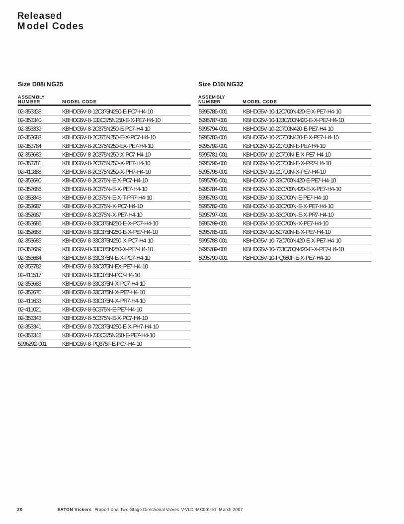
Released Model Codes
02-353338 KBHDG5V-8-12C375N250-E-PC7-H4-1002-353340 KBHDG5V-8-133C375N250-E-X-PE7-H4-1002-353339 KBHDG5V-8-2C375N250-E-PC7-H4-1002-353688 KBHDG5V-8-2C375N250-E-X-PC7-H4-1002-353784 KBHDG5V-8-2C375N250-EX-PE7-H4-1002-353689 KBHDG5V-8-2C375N250-X-PC7-H4-1002-353781 KBHDG5V-8-2C375N250-X-PE7-H4-1002-411888 KBHDG5V-8-2C375N250-X-PH7-H4-1002-353690 KBHDG5V-8-2C375N-E-X-PC7-H4-1002-352666 KBHDG5V-8-2C375N-E-X-PE7-H4-1002-353846 KBHDG5V-8-2C375N-E-X-T-PR7-H4-1002-353687 KBHDG5V-8-2C375N-X-PC7-H4-1002-352667 KBHDG5V-8-2C375N-X-PE7-H4-1002-353686 KBHDG5V-8-33C375N250-E-X-PC7-H4-1002-352668 KBHDG5V-8-33C375N250-E-X-PE7-H4-1002-353685 KBHDG5V-8-33C375N250-X-PC7-H4-1002-352669 KBHDG5V-8-33C375N250-X-PE7-H4-1002-353684 KBHDG5V-8-33C375N-E-X-PC7-H4-1002-353782 KBHDG5V-8-33C375N-EX-PE7-H4-1002-411517 KBHDG5V-8-33C375N-PC7-H4-1002-353683 KBHDG5V-8-33C375N-X-PC7-H4-1002-352670 KBHDG5V-8-33C375N-X-PE7-H4-1002-411633 KBHDG5V-8-33C375N-X-PR7-H4-1002-411021 KBHDG5V-8-5C375N-E-PE7-H4-1002-353343 KBHDG5V-8-5C375N-E-X-PC7-H4-1002-353341 KBHDG5V-8-72C375N250-E-X-PH7-H4-1002-353342 KBHDG5V-8-733C375N250-E-PE7-H4-105996292-001 KBHDG5V-8-PQ375F-E-PC7-H4-10
5995786-001 KBHDG5V-10-12C700N420-E-X-PE7-H4-105995787-001 KBHDG5V-10-133C700N420-E-X-PE7-H4-105995794-001 KBHDG5V-10-2C700N420-E-PE7-H4-105995783-001 KBHDG5V-10-2C700N420-E-X-PE7-H4-105995792-001 KBHDG5V-10-2C700N-E-PE7-H4-105995781-001 KBHDG5V-10-2C700N-E-X-PE7-H4-105995796-001 KBHDG5V-10-2C700N-E-X-PR7-H4-105995798-001 KBHDG5V-10-2C700N-X-PE7-H4-105995795-001 KBHDG5V-10-33C700N420-E-PE7-H4-105995784-001 KBHDG5V-10-33C700N420-E-X-PE7-H4-105995793-001 KBHDG5V-10-33C700N-E-PE7-H4-105995782-001 KBHDG5V-10-33C700N-E-X-PE7-H4-105995797-001 KBHDG5V-10-33C700N-E-X-PR7-H4-105995799-001 KBHDG5V-10-33C700N-X-PE7-H4-105995785-001 KBHDG5V-10-5C720N-E-X-PE7-H4-105995788-001 KBHDG5V-10-72C700N420-E-X-PE7-H4-105995789-001 KBHDG5V-10-733C700N420-E-X-PE7-H4-105995790-001 KBHDG5V-10-PQ680F-E-X-PE7-H4-10
ASSEMBLY NUMBER MODEL CODE
ASSEMBLY NUMBER MODEL CODE
Size D08/NG25 Size D10/NG32

© 2007 Eaton CorporationAll Rights ReservedPrinted in USADocument No. V-VLDI-MC001-E1Supersedes V-VLDI-MC001-EMarch 2007
Eaton14615 Lone Oak RoadEden Prairie, MN 55344USATel: 952 937-9800Fax: 952 974-7722www.hydraulics.eaton.com
EatonDr.-Reckeweg-Str. 1D-76532 Baden-BadenGermanyTel: (49) 7221 682-0Fax: (49) 7221 682-788
Eaton20 Rosamond RoadFootscrayVictoria 3011AustraliaTel: (61) 3 9319 8222Fax: (61) 3 9318 5714