Embed Size (px)
Citation preview

cod. 1-5302-826
WORKSHOP MANUALGEARBOX


PREFACE
- Every attempt has been made to present within this service manual, accurate and up to date technicalinformation.However, development on the LOMBARDINI series is continuous.Therefore, the information within this manual is subject to change without notice and without obligation.
- The information contained within this service manual is the sole property of LOMBARDINI.As such, no reproduction or replication in whole or part is allowed without the express written permission ofLOMBARDINI.
Information presented within this manual assumes the following:
1 - The person or people performing service work on LOMBARDINI series engines is properly trained andequipped to safely and professionally perform the subject operation;
2 - The person or people performing service work on LOMBARDINI series engines possesses adequate hand andLOMBARDINI special tools to safely and professionally perform the subject service operation;
3 - The person or people performing service work on LOMBARDINI series engines has read the pertinentinformation regarding the subject service operations and fully understands the operation at hand.
- This manual was written by the manufacturer to provide technical and operating information to authorisedLOMBARDINI after-sales service centres to carry out assembly, disassembly, overhauling, replacement and tuningoperations.
- As well as employing good operating techniques and observing the right timing for operations, operators must readthe information very carefully and comply with it scrupulously.
- Time spent reading this information will help to prevent health and safety risks and financial damage.Written information is accompanied by illustrations in order to facilitate your understanding of every step of theoperating phases.
- 3 -Workshop Manual Gearbox_cod. 1.5302.826_.1° ed_ rev. 0
GEARBOX

- 4 - Workshop Manual Gearbox_cod. 1.5302.826_.1° ed_ rev. 00
CUSE/ATLO15.03.20081° 00 15.03.20081-5302-826 51177
REGISTRATION OF MODIFICATIONS TO THE DOCUMENT
Any modifications to this document must be registered by the drafting body, by completing the following table.
Draftingbody
Documentcode Edition Issue date
Reviewdate
ModelN° Revision Endorsed

- 5 -Workshop Manual Gearbox_cod. 1.5302.826_.1° ed_ rev. 0
This manual contains the most important information for the repair GEARBOX.This information is current upto15.03.2008.
INTRODUCTION
TABLE OF CONTENTS
1 GENERAL REMARKS AND SAFETY INFORMATION........................................................................ Pag. 7-9
WARRANTY CERTIFICATE................................................................................................................................................ 7GENERAL SERVICE MANUAL NOTES .............................................................................................................................. 7SAFETY AND WARNING DECALS ..................................................................................................................................... 7SAFETY REGULATIONS ................................................................................................................................................. 8-9GENERAL SAFETY DURING OPERATING PHASES ......................................................................................................... 9SAFETY AND ENVIROMENTAL IMPACT ............................................................................................................................ 9
2 TECHNICAL INFORMATION .................................................................................................................. 10-11
GEARBOX TECHNICAL SPECIFICATIONS ..................................................................................................................... 10GERARBOX MAINTENANCE ............................................................................................................................................ 10EXTRAORDINARY MAINTENANCE .................................................................................................................................. 10ORDINARY MAINTENANCE.............................................................................................................................................. 10OIL CHANGE .................................................................................................................................................................... 11OIL LEVEL CHECK........................................................................................................................................................... 11
3 DISASSEMBLY ....................................................................................................................................... 12-21
GEARBOX ........................................................................................................................................................................ 12FLANGES ......................................................................................................................................................................... 13GEAR CONSENT SENSORS ...................................................................................................................................... 13-14GERABOX OIL CHANGE .................................................................................................................................................. 14OIL SEALS ........................................................................................................................................................................ 144 WD COUPLING BOX ..................................................................................................................................................... 15GEARBOX ........................................................................................................................................................................ 15GEAR SELECTOR PLUGS .............................................................................................................................................. 15PUSH-ROD PLUG ............................................................................................................................................................ 15GEARBOX HOUSING ....................................................................................................................................................... 16SEMI-HOUSINGS ......................................................................................................................................................... 16-194WD SELECTOR ........................................................................................................................................................ 19-21
4 REASSEMBLY ....................................................................................................................................... 22-35
SEMI-HOUSING ................................................................................................................................................................ 22IDLE GEAR SHAFT PIN OF THE REVERSE GEAR ......................................................................................................... 22OUTPUT DRIVE SHAFT ................................................................................................................................................... 23PRIMARY INPUT DRIVE SHAFT ....................................................................................................................................... 23INTERMEDIATE SHAFT.................................................................................................................................................... 25GEAR UNITS - REASSEMBLY..................................................................................................................................... 26-27REVERSE GEAR SHAFT ............................................................................................................................................ 27-304 WD BOX ................................................................................................................................................................... 30-334 WD COUPLING BOX - REASSEMBLY ..................................................................................................................... 33-35
5 SPECIAL TOOLS ..........................................................................................................................................36

- 6 - Workshop Manual Gearbox_cod. 1.5302.826_.1° ed_ rev. 00
. .....................................................................................................................................................
. .....................................................................................................................................................
. .....................................................................................................................................................
. .....................................................................................................................................................
. .....................................................................................................................................................
. .....................................................................................................................................................
. .....................................................................................................................................................
. .....................................................................................................................................................
. .....................................................................................................................................................
. .....................................................................................................................................................
. .....................................................................................................................................................
. .....................................................................................................................................................
. .....................................................................................................................................................
. .....................................................................................................................................................
. .....................................................................................................................................................
. .....................................................................................................................................................
. .....................................................................................................................................................
. .....................................................................................................................................................
. .....................................................................................................................................................
. .....................................................................................................................................................
. .....................................................................................................................................................
. .....................................................................................................................................................
. .....................................................................................................................................................
. .....................................................................................................................................................
. .....................................................................................................................................................
. .....................................................................................................................................................
. .....................................................................................................................................................
. .....................................................................................................................................................

- 7 -Workshop Manual Gearbox_cod. 1.5302.826_.1° ed_ rev. 0
1
- The products manufactured by LOMBARDINI Srl are warranted to be free from conformity defects for a period of 24 months fromthe date of delivery to the first end user.
- For engines fitted to stationary equipment, working at constant load and at constant and/or slightly variable speed within the settinglimits, the warranty covers a period up to a limit of 2000 working hours, if the above mentioned period (24 months) is not expired.
- If no hour-meter is fitted , 12 working hours per calendar day will be considered.- For what concerns the parts subject to wear and deterioration (injection/feeding system, electrical system, cooling system, sealing
parts, non-metallic pipes, belts) warranty covers a maximum limit of 2000 working hours, if the above mentioned period (24 months)is not expired.
- For correct maintenance and replacement of these parts, it is necessary to follow the instructions reported in the documentationsupplied with each engine.
- To ensure the engine warranty is valid, the engine installation, considering the product technical features, must be carried out byqualified personnel only.
- The list of the LOMBARDINI authorized dealers is reported in the “Service” booklet, supplied with each engine.- Special applications involving considerable modifications to the cooling/lubricating system (for ex.: dry oil sump), filtering system,
turbo-charged models, will require special written warranty agreements.- Within the above stated periods LOMBARDINI Srl directly or through its authorized network will repair and/or replace free of charge
any own part or component that, upon examination by LOMBARDINI or by an authorized LOMBARDINI agent, is found to bedefective in conformity, workmanship or materials.
- Any other responsibility/obligation for different expenses, damages and direct/indirect losses deriving from the engine use or fromboth the total or partial impossibility of use, is excluded.
- The repair or replacement of any component will not extend or renew the warranty period.
LOMBARDINI warranty obligations here above described will be cancelled if:
- LOMBARDINI engines are not correctly installed and as a consequence the correct functional parameters are not respectedand altered.
- LOMBARDINI engines are not used according to the instructions reported in the “Use and Maintenance” booklet supplied witheach engine.
- Any seal affixed to the engine by LOMBARDINI has been tampered with or removed.- Spare parts used are not original LOMBARDINI.- Feeding and injection systems are damaged by unauthorized or poor quality fuel types.- Electrical system failure is due to components, connected to this system, which are not supplied or installed by LOMBARDINI.- Engines have been disassembled, repaired or altered by any part other than an authorized LOMBARDINI agent.
- Following expiration of the above stated warranty periods and working hours, LOMBARDINI will have no further responsibility forwarranty and will consider its here above mentioned obligations for warranty complete.
- Any warranty request related to a non-conformity of the product must be addressed to the LOMBARDINI Srl service agents.
GENERAL SERVICE MANUAL NOTES
1 - Use only genuine Lombardini repair parts.Failure to use genuine Lombardini parts could result in sub-standard performance and low longevity.
2 - All data presented are in metric format. That is, dimensions are presented in millimeters (mm), torque is presented in Newton-meters (Nm), weight is presented in kilograms (Kg), volume is presented in liters or cubic centimeters (cc) and pressure ispresented in barometric units (bar).
GENERAL REMARKS AND SAFETY INFORMATION
WARRANTY CERTIFICATE
- Important remarks and features of the text are highlightedusing symbols, which are explained below:
Danger – AttentionThis indicates situations of grave danger which, if ignored,may seriously threaten the health and safety of individuals.
SAFETY AND WARNING DECALS
Caution – WarningThis indicates that it is necessary to take proper precautionsto prevent any risk to the health and safety of individuals andavoid financial damage.
ImportantThis indicates particularly important technical informationthat should not be ignored.

- 8 - Workshop Manual Gearbox_cod. 1.5302.826_.1° ed_ rev. 00
1
• LOMBARDINI Engines are built to supply their performances in a safe and long-lasting way.To obtain these results, it is essential for users to comply with the servicing instructions given in the relative manual along with thesafety recommendations listed below.
• The engine has been made according to a machine manufacturer's specifications and all actions required to meet the essentialsafety and health safeguarding requisites have been taken, as prescribed by the current laws in merit.All uses of the engine beyond those specifically established cannot therefore be considered as conforming to the use defined byLOMBARDINI which thus declines all liability for any accidents deriving from such operations.
• The following indications are dedicated to the user of the machine in order to reduce or eliminate risks concerning engine operationin particular, along with the relative routine maintenance work.
• The user must read these instructions carefully and become familiar with the operations described.Failure to do this could lead to serious danger for his personal safety and health and that of any persons who may be in the vicinityof the machine.
• The engine may only be used or assembled on a machine by technicians who are adequately trained about its operation and thederiving dangers.This condition is also essential when it comes to routine and, above all, extraordinary maintenance operations which, in the lattercase, must only be carried out by persons specifically trained by LOMBARDINI and who work in compliance with the existingdocumentation.
• Variations to the functional parameters of the engine, adjustments to the fuel flow rate and rotation speed, removal of seals,demounting and refitting of parts not described in the operation and maintenance manual by unauthorized personnel shall relieveLOMBARDINI from all and every liability for deriving accidents or for failure to comply with the laws in merit.
• On starting, make sure that the engine is as horizontal as possible, unless the machine specifications differ.In the case of manual start-ups, make sure that the relative actions can take place without the risk of hitting walls or dangerousobjects, also considering the movements made by the operator.Pull-starting with a free cord (thus excluding self-winding starting only), is not permitted even in an emergency.
• Make sure that the machine is stable to prevent the risk of overturning.• Become familiar with how to adjust the rotation speed and stop the engine.• Never start the engine in a closed place or where there is insufficient ventilation.
Combustion creates carbon monoxide, an odourless and highly poisonous gas.Lengthy stays in places where the engine freely exhausts this gas can lead to unconsciousness and death.
• The engine must not operate in places containing inflammable materials, in explosive atmospheres, where there is dust that caneasily catch fire unles specific, adequate and clearly indicated precautions have been taken and have been certified for the machine.
• To prevent fire hazards, always keep the machine at least one meter from buildings or from other machinery.• Children and animals must be kept at a due distance from operating machines in order to prevent hazards deriving from their
operation.• Fuel is inflammable.
The tank must only be filled when the engine is off.Thoroughly dry any spilt fuel and move the fuel container away along with any rags soaked in fuel or oil.Make sure that no soundproofing panels made of porous material are soaked in fuel or oil.Make sure that the ground or floor on which the machine is standing has not soaked up any fuel or oil.
• Fully tighten the tank plug each time after refuelling.Do not fill the tank right to the top but leave an adequate space for the fuel to expand.
• Fuel vapour is highly toxic.Only refuel outdoors or in a well ventilated place.
• Do not smoke or use naked flames when refuelling.• The engine must be started in compliance with the specific instructions in the operation manual of the engine and/or machine
itself.Do not use auxiliary starting aids that were not installed on the original machine (e.g. Startpilot’).
• Before starting, remove any tools that were used to service the engine and/or machine.Make sure that all guards have been refitted.
• During operation, the surface of the engine can become dangerously hot.Avoid touching the exhaust system in particular.
• Before proceeding with any operation on the engine, stop it and allow it to cool.Never carry out any operation whilst the engine is running.
• The coolant fluid circuit is under pressure.Never carry out any inspections until the engine has cooled and even in this case, only open the radiator plug or expansionchamber with the utmost caution, wearing protective garments and goggles. If there is an electric fan, do not approach theengine whilst it is still hot as the fan could also start operating when the engine is at a standstill.Only clean the coolant system when the engine is at a standstill.
• When cleaning the oil-cooled air filter, make sure that the old oil is disposed of in the correct way in order to safeguard theenvironment.The spongy filtering material in oil-cooled air filters must not be soaked in oil.The reservoir of the separator pre-filter must not be filled with oil.
• The oil must be drained whilst the engine is hot (oil T ~ 80°C).Particular care is required to prevent burns.
SAFETY REGULATIONS
General remarks and safety information

- 9 -Workshop Manual Gearbox_cod. 1.5302.826_.1° ed_ rev. 0
1
Do not allow the oil to come into contact with the skin.• Pay attention to the temperature of the oil filter when the filter itself is replaced.• Only check, top up and change the coolant fluid when the engine is off and cold.
Take care to prevent fluids containing nitrites from being mixed with others that do not contain these substances since"Nitrosamine", dangerous for the health, can form.The coolant fluid is polluting and must therefore be disposed of in the correct way to safeguard the environment.
• During operations that involve access to moving parts of the engine and/or removal of rotating guards, disconnect and insulatethe positive wire of the battery to prevent accidental short-circuits and to stop the starter motor from being energized.
• Only check belt tension when the engine is off.• Only use the eyebolts installed by LOMBARDINI to move the engine.
These lifting points are not suitable for the entire machine; in this case, the eyebolts installed by the manufacturer should beused.
General remarks and safety information
GENERAL SAFETY DURING OPERATING PHASES
– The procedures contained in this manual have been tested and selected by the manufacturer’s technical experts, and hence areto be recognised as authorised operating methods.
– A number of procedures must be carried out with the aid of equipment and tools that simplify and improve the timing of operations.– All tools must be in good working condition so that engine components are not damaged and that operations are carried out properly
and safely.It is important to wear the personal safety devices prescribed by work safety laws and also by the standards of this manual.
– Holes must be lined up methodically and with the aid of suitable equipment. Do not use your fingers to carry out this operation toavoid the risk of amputation.
– Some phases may require the assistance of more than one operator. If so, it is important to inform and train them regarding thetype of activity they will be performing in order to prevent risks to the health and safety of all persons involved.
– Do not use flammable liquids (petrol, diesel, etc.) to degrease or wash components. Use special products.– Use the oils and greases recommended by the manufacturer.
Do not mix different brands or combine oils with different characteristics.– Discontinue use of the engine if any irregularities arise, particularly in the case of unusual vibrations.– Do not tamper with any devices to alter the level of performance guaranteed by the manufacturer.
SAFETY AND ENVIRONMENTAL IMPACT
Every organisation has a duty to implement procedures to identify,assess and monitor the influence of its own activities (products,services, etc.) on the environment.Procedures for identifying the extent of the impact on theenvironment must consider the following factors:
- Liquid waste - Waste management - Soil contamination - Atmospheric emissions - Use of raw materials and natural resources - Regulations and directives regarding environmental impact
In order to minimise the impact on the environment, themanufacturer now provides a number of indications to be followedby all persons handling the engine, for any reason, during itsexpected lifetime.
- All packaging components must be disposed of in accordancewith the laws of the country in which disposal is taking place.
- Keep the fuel and engine control systems and the exhaustpipes in efficient working order to limit environmental and noisepollution.
- When discontinuing use of the engine, select all componentsaccording to their chemical characteristics and dispose ofthem separately.

- 10 - Workshop Manual Gearbox_cod. 1.5302.826_.1° ed_ rev. 00
100
AMBRASTANDARD
TRANSHYDRAULIC
134-DCNH 86556175
1,2
2
SAE 80W-90API GL-5
TECHNICAL INFORMATION
Danger – Attention- The used engine oil can cause skin-cancer if kept frequently in contact for prolonged periods.- If contact with oil cannot be avoided, wash carefully your hands with water and soap as soon as possible.- Do not disperse the oil in the ambient, as it has a high pollution power.
Litres
GEARBOX MAINTENANCE
WarningFailure to respect the operations described below can lead to technical damage to the gearbox and to thecar on which it is mounted
Gearbox oil change
EXTRAORDINARY MAINTENANCE
AFTER THE FIRST 50 WORKING HOURS
ORDINARY MAINTENANCE
LEVEL ENGINE
OPERATION DESCRIPTIONFREQUENCY x HOURS
CHECK
GEARBOX TECHNICAL SPECIFICATIONS
4WD coupling exit gear ratios Slow forward: 8.40:1
Fast forward: 5.28:1
Reverse gear: 7.0:1
specifications
PRESCRIBED LUBRICANT
OIL VOLUME AT MAX LEVEL
OIL CAPACITY

- 11 -Workshop Manual Gearbox_cod. 1.5302.826_.1° ed_ rev. 0
8
7
4 5 6
1
3 2
7
8
6
2Technical information
Gearbox
External components:
1 Gear consent sensors2 Odometer sensor (if mounted).3 Transmission flanges4 Main input drive shaft5 4WD coupling box6 Oil drain plug7 Oil level plug8 Vent plug and oil filler plug.
Oil change
Gear box oil change
Position the car on a level surface and unscrew the oil drainplug 6 to drain the oil from the gear box.
ImportantPlug 6 is magnetised to gather the metal particles.Clean it carefully and replace the sealing washer beforereassembling it.
Unscrew oil level plug 7.Unscrew oil filler plug 8 and add the quantity of oil specified.Via oil level plug 7 check the overflow of excessive oil, or thereaching of the correct oil level that should remain 5 mmbelow the hole of plug 7
Caution - WarningPlug 8 is provided with a vent hole, therefore you mustreassemble it in the same position.
Screw on oil level plug 7 and oil filler plug 8.
Oil level - Check
Position the car on a level surface and unscrew the oil levelplug 7.Check that the oil level is 5 mm under the hole of plug 7,otherwise top up via the hole of oil filler plug 8.

- 12 - Workshop Manual Gearbox_cod. 1.5302.826_.1° ed_ rev. 00
1
2
1
3 2
7
4
5 6
3
1
8
2
3
4
1
2
Gearbox
External components:
1 Gear consent sensors2 Odometer sensor (if mounted).3 Transmission flanges4 Main input drive shaft5 4WD coupling box6 Oil drain plug7 Oil level plug8 Vent plug and oil filler plug.
ImportantBefore starting any operation on the gearbox carefully protect theelectric sensors of gear consent (1) and odometer (2) sensors (ifmounted).Never clean the gearbox with a high pressure water jet.
DISASSEMBLY
Insert tool 1 code 175.3675.041.8 for closing the transmission flange 2 fordisassembling both the forward transmission flange and the 4WD.

- 13 -Workshop Manual Gearbox_cod. 1.5302.826_.1° ed_ rev. 0
3
6
1
2
54 3 1 2
7
8
2
4 3 2 1
Disassembly
Disassemble odometer 1 (if mounted) and gear consent sensors 2.
Flanges
Components:
1 Main transmission flange2 Self-locking flanged nut M16x1.53 4WD transmission flange4 Self-blocking flanged nut M12x1.25
ImportantGear consent sensors 2 should be disassembled together with thesupports.
Gear consent sensors
Components:
1 Consent sensor2 Sensor spring3 Ball4 Ball and spring holder bushing
- 14 - Workshop Manual Gearbox_cod. 1.5302.826_.1° ed_ rev. 00
A
A
1
9
10
3
11
12
P
P
P
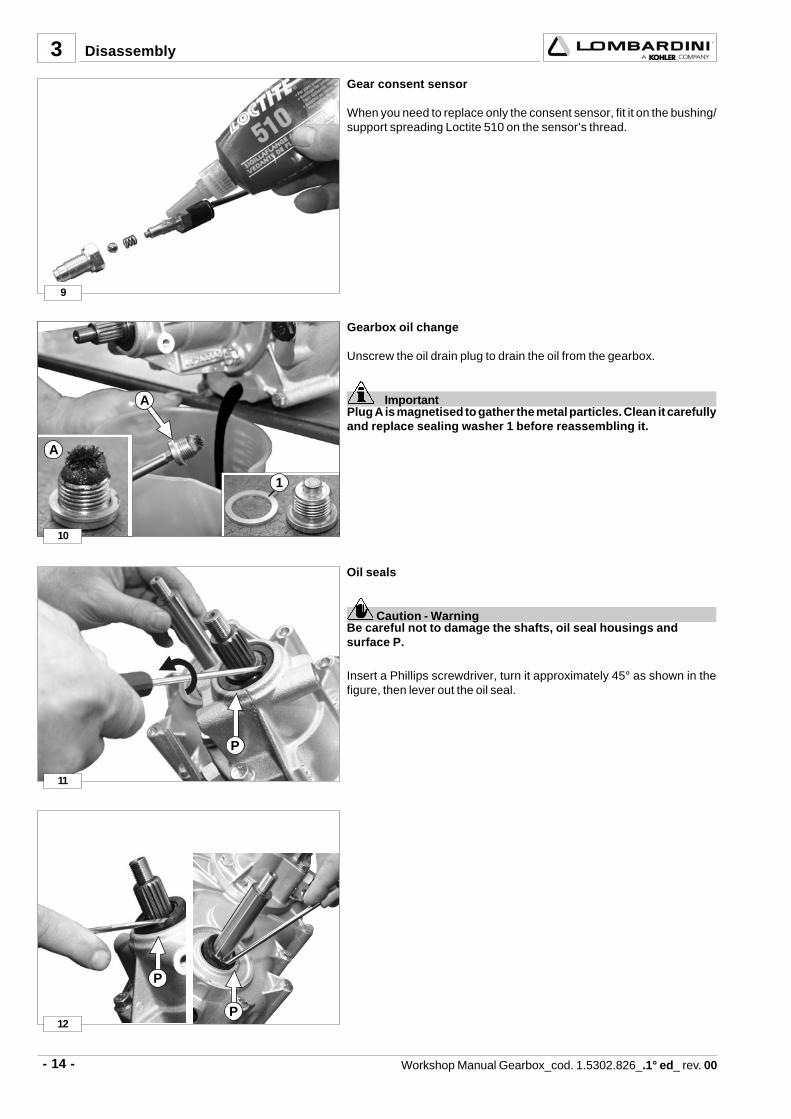
Gear consent sensor
When you need to replace only the consent sensor, fit it on the bushing/support spreading Loctite 510 on the sensor’s thread.
Gearbox oil change
Unscrew the oil drain plug to drain the oil from the gearbox.
ImportantPlug A is magnetised to gather the metal particles. Clean it carefullyand replace sealing washer 1 before reassembling it.
Disassembly
Oil seals
Caution - WarningBe careful not to damage the shafts, oil seal housings andsurface P.
Insert a Phillips screwdriver, turn it approximately 45° as shown in thefigure, then lever out the oil seal.

- 15 -Workshop Manual Gearbox_cod. 1.5302.826_.1° ed_ rev. 0
3
13
14
SR
12
1
15
16
1
2
5 3 2 1
4 123
Disassembly
4WD coupling box
ImportantBefore starting the disassembly make a reference mark (R) for theoriginal position.The 4WD gear selector (S) should be disconnected (gear selectorlever positioned towards the gearbox) for both disassembly andreassembly.
Unscrew the 6 M8 fastening screws from the 4WD box and take out thebox.
1 - 2 M8x1.25 L75 flanged screws.2 - 4 M8x1.25 L25 flanged screws.
Gearbox
Disassemble the D 20 lock snap ring and remove the 4WD fixed couplingbushing 1.
Remove the plugs of the gear selector housing 1.Remove the plug of the safety push-rod housing 2.
Gear selector plugs
Components:
1 Gear selector ball housing plug2 Gear selector ball spring3 Selector ball
Push-rod plug
Components:
4 Safety push-rod plug5 Safety push-rod

- 16 - Workshop Manual Gearbox_cod. 1.5302.826_.1° ed_ rev. 00
17
18
1
2
3
4
3
19
20
1
2
2
Gearbox housing
Unscrew all the screws that keep the two semi-housings together.
1. 5 M8x1.25 L160 screws2. 2 M8x1.25 L150 screws3. 4 M8x1.25 L140 screws4. 3 M8x1.25 L 55 screws
Disassembly
Semi-housings
Strike alternately on the semi-housings on the position shown 1, and onoutput drive shaft 2 to separate the two semi-housings.

- 17 -Workshop Manual Gearbox_cod. 1.5302.826_.1° ed_ rev. 0
3
23
24
1
2
3
45
21
22
3
2
1
D
1
2
3
3
1
Disassembly
Strike alternately on the input drive shaft 3 and output shaft 1 tocontemporaneously take out the three shafts of the left semi-housing.
Components
1 Output drive shaft2 Intermediate shaft3 Primary input drive shaft4 Reverse gear shaft5 Left semi-housing
Take out right semi-housing D.
Main components:
1 Primary input drive shaft2 Output drive shaft3 Intermediate shaft
Important
Before taking out the gearbox shafts remove clearance washer 1, idlegear with bushing 2 and the second clearance washer 3

- 18 - Workshop Manual Gearbox_cod. 1.5302.826_.1° ed_ rev. 00
25
26
3
3
21
27
28
4
5
To disassemble the bearings use a bearing extractor available on themarket.
Use pliers for SP type external safety rings, to proceed with the disassemblyof the other components.
Disassembly
Take out bearing 1 and the first gear 2 using a universal extractor, thenremove roller cage 3, the swivel ring 4 and reverse gear 5

- 19 -Workshop Manual Gearbox_cod. 1.5302.826_.1° ed_ rev. 0
3
8
6
6
7
29
30
9
10
11
32
33
317
8
Disassembly
4WD Selector
Loosen self-locking nut 11 fastening the gear selector 10
Take out safety ring 9 of the selector pin
Take out safety ring 6 using pliers for SP type seeger rings
Dismount clearance washer 7 and the idle gear of the fast gear

- 20 - Workshop Manual Gearbox_cod. 1.5302.826_.1° ed_ rev. 00
5 6
8
734
35
3
2
3
6
4
36
37
Disassembly
Dismount the selector spring holder bushing 7 and selector pin bushing8
Moving selector pin 6 towards the outside take out bushing 5
Take out safety ring 4 that fastens the 4WD drive shaft
Moving selector pin 6 towards the outside take out drive shaft 2 alongwith bearings 3

- 21 -Workshop Manual Gearbox_cod. 1.5302.826_.1° ed_ rev. 0
3
6
38
. .....................................................................................................................................................
. .....................................................................................................................................................
. .....................................................................................................................................................
. .....................................................................................................................................................
. .....................................................................................................................................................
. .....................................................................................................................................................
. .....................................................................................................................................................
. .....................................................................................................................................................
. .....................................................................................................................................................
. .....................................................................................................................................................
. .....................................................................................................................................................
. .....................................................................................................................................................
. .....................................................................................................................................................
. .....................................................................................................................................................
. .....................................................................................................................................................
. .....................................................................................................................................................
. .....................................................................................................................................................
. .....................................................................................................................................................
. .....................................................................................................................................................
. .....................................................................................................................................................
. .....................................................................................................................................................
. .....................................................................................................................................................
Disassembly
Take out selector pin 6

- 22 - Workshop Manual Gearbox_cod. 1.5302.826_.1° ed_ rev. 00
39
40
41
42
OR
OR
SS
4 REASSEMBLY
ImportantCheck that the two centring pins S are in their correct place and,if damaged, replace them.
Check the integrity of the O-rings of the two selector rods and theircorrect positioning
ImportantIf damaged, replace the O-rings before reassembly.
Semi-housing
Clean off with a scraper, any sealant residue on the coupling surfacesof the two semi-housings.
ImportantClean carefully with degreaser liquid.
Idle gear shaft pin of the reverse gear
Start reassembling from the left semi-housing, positioning the idlegear shaft pin of the reverse gear.

- 23 -Workshop Manual Gearbox_cod. 1.5302.826_.1° ed_ rev. 0
43
44
45
A
8
8 7
2 2 23 31 4 5 6 7
1
7
46
3
4
4
Rest on a suitable support for assembling the main input drive shaft.
- Position input drive shaft 8 with the tang for pulley connection downwards,with bearing 7 already inserted.
- Assemble gear 1 with the recess for selector fork A turned downwardsas in the figure.
Primary input drive shaft
Components:
1 Fast gear running gear2 Safety snap ring3 Toothed clearance washer4 Roller cage5 Slow gear idle gear6 Reverse gear pinion7 Bearing8 Input drive shaft
Output drive shaft
Mount the bearings on the output drive shaft.
Reassembly
- Insert safety ring 2 in the appropriate housing using pliers for seegerrings.
ImportantApply grease to toothed clearance washer 3 so that it does notmove from the shaft slot.If toothed clearance washer 3 moves it could block the gear.
- Mount toothed clearance washer 3.
Insert roller cage 4 and oil it.

- 24 - Workshop Manual Gearbox_cod. 1.5302.826_.1° ed_ rev. 00
47
49
50
2
3
5
6
7
48
3
4
Mount bearing 7 to its limit stop.
Mount the gear of the reverse gear pinion 6.
Mount slow gear idle gear 5.
Mount in sequence toothed clearance washer 3 and the second safetysnap ring 2, taking care to insert it properly in the housing.
Reassembly
Insert the third safety ring 3 on the last slot.
- 25 -Workshop Manual Gearbox_cod. 1.5302.826_.1° ed_ rev. 0
51
52
53
54
1
10
2
3 4 65 7 8 9
3
2
G
C
6
9
8
7
4
5
4
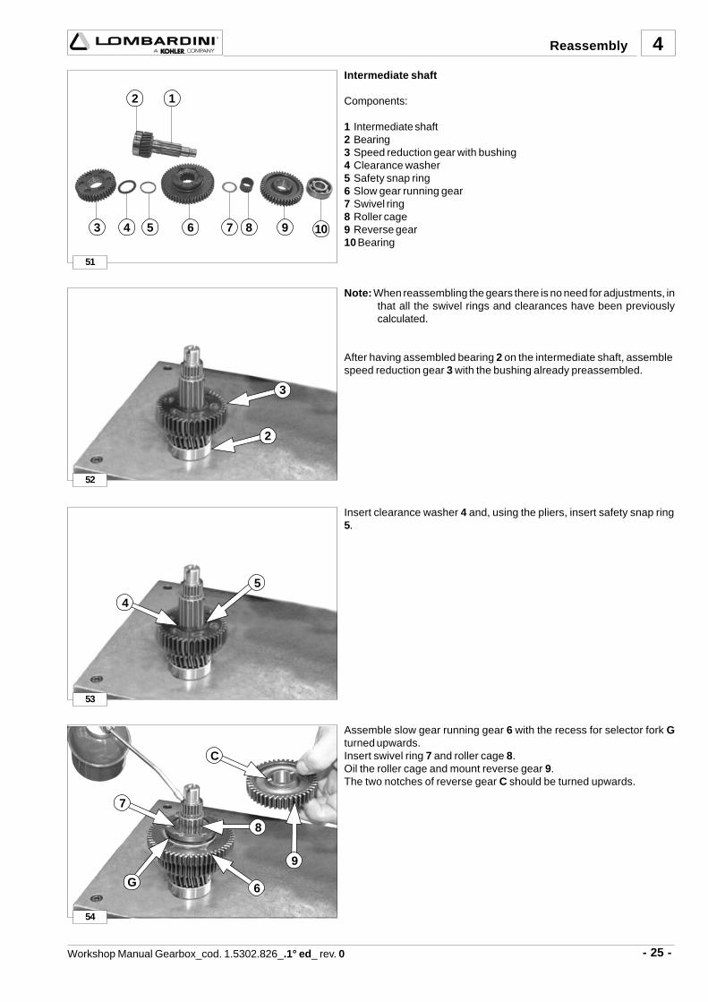
Insert clearance washer 4 and, using the pliers, insert safety snap ring5.
Assemble slow gear running gear 6 with the recess for selector fork Gturned upwards.Insert swivel ring 7 and roller cage 8.Oil the roller cage and mount reverse gear 9.The two notches of reverse gear C should be turned upwards.
Note: When reassembling the gears there is no need for adjustments, inthat all the swivel rings and clearances have been previouslycalculated.
After having assembled bearing 2 on the intermediate shaft, assemblespeed reduction gear 3 with the bushing already preassembled.
Intermediate shaft
Components:
1 Intermediate shaft2 Bearing3 Speed reduction gear with bushing4 Clearance washer5 Safety snap ring6 Slow gear running gear7 Swivel ring8 Roller cage9 Reverse gear10 Bearing
Reassembly

- 26 - Workshop Manual Gearbox_cod. 1.5302.826_.1° ed_ rev. 00
55
56
57
58
10
3
4
1
2
5
6
2
7
5
4
Mount bearing 10 to its limit stop.
Gear units - Reassembly
ImportantTo correctly insert the shafts you should support the left semi-housing in order to set it to a proper distance from the workbench.
Proceed only as described below to reassemble the units in the semi-housing:
a- Mount reverse gear shaft 1.b- Lay down and keep at a slant (see photo), the primary input drive shaft
2, complete with selector fork rod 3 in the 4WD left semi-housing,without inserting bearing 4 into its housing.
c- Assemble at the same time intermediate shaft 5 along with selectorfork rod 7 and output drive shaft 6 proceeding as follows:Bring shafts 5 and 6 near to their seats and then insert all three shafts2, 5 and 6 into their seats.
Rotate the shafts manually to check if they run smoothly, making surethat they are free from impediments.
Reassembly

- 27 -Workshop Manual Gearbox_cod. 1.5302.826_.1° ed_ rev. 0
59
60
61
62
8
2 3 4 3
1
1
4
3
4
Position the selector fork rods so that notches 8 of the safety system(and safety pin) are not aligned.
Reverse gear shaft
Components:
1 Reverse gear shaft2 Safety snap ring3 Clearance washer4 Idle gear + bushing
Mount the following components in sequence on reverse gear shaft 1:
1) snap ring 2;2) washer 3;3) idle gear with bushing 4;4) second washer 3.
Oil all bearings before closing the gearbox with the right semi-housing.
Reassembly

- 28 - Workshop Manual Gearbox_cod. 1.5302.826_.1° ed_ rev. 00
63
64
65
66
4
Grease the selector fork rods.
Apply Loctite sealant 510 on the seal surface.Apply sealant evenly over the whole surface.
Assemble the two semi-housings with the help of a tool.
Tighten service screws M 8x1.25 ( L55 ) at a torque of 30 Nm.
Reassembly

- 29 -Workshop Manual Gearbox_cod. 1.5302.826_.1° ed_ rev. 0
67
68
69
70
A B
C
P
S
S
4
Insert the selector stop balls A, springs B, and plugs C.
Tighten plugs at a torque of 25 Nm.
Insert safety pin S and check that it functions correctly.
The purpose of safety pin S is to avoid the accidental or intentionalinsertion of more than one gear at a time.
With the idle gear inserted, pin S is free inside its housing.
With the gear inserted, safety pin S is forced in the housing that is on bothselector rods, thus blocking the unused rod.
Amply grease the housing of pin P.
Reassembly

- 30 - Workshop Manual Gearbox_cod. 1.5302.826_.1° ed_ rev. 00
71
72
73
74
1083 4 5 6
1
2 7 9 11
612
12
2
3
6
4
Apply Loctite 510 on the safety pin plug.
Tighten the plug at a torque of 25 Nm
4WD box
Components:
1 4WD coupling box 2 4WD drive shaft 3 4WD drive shaft bearings 4 Seeger safety ring 5 4WD coupling running bushing 6 Selector pin 7 Spring holder selector bushing 8 Selector pin bushing 9 Safety ring10 Selector lever11 Self-locking nut M8x 1.2512 Selector pin O-ring
Insert selector pin 6 in the appropriate housing.
ImportantBefore reassembling check the state of the O-ring 12.
Pulling selector pin 6 towards the outside insert 4WD drive shaft 2 alongwith the already mounted bearings 3.
Reassembly

- 31 -Workshop Manual Gearbox_cod. 1.5302.826_.1° ed_ rev. 0
75
76
77
78
4
5 6
8
8
7
4
Insert safety ring 4 to block the 4WD drive shaft.
Insert 4WD coupling running bushing 5, assuring that selector pin 6 isinserted correctly in the recess of the bushing.
Montare e serrare la boccola 8 sul perno selettore ad una coppia di25 Nm.
Mount bushing 8 on the selector pin
Tighten at a torque of 25 Nm.
Reassembly
- 32 - Workshop Manual Gearbox_cod. 1.5302.826_.1° ed_ rev. 00
79
80
81
82
9
10
11
13
S
2
1
4
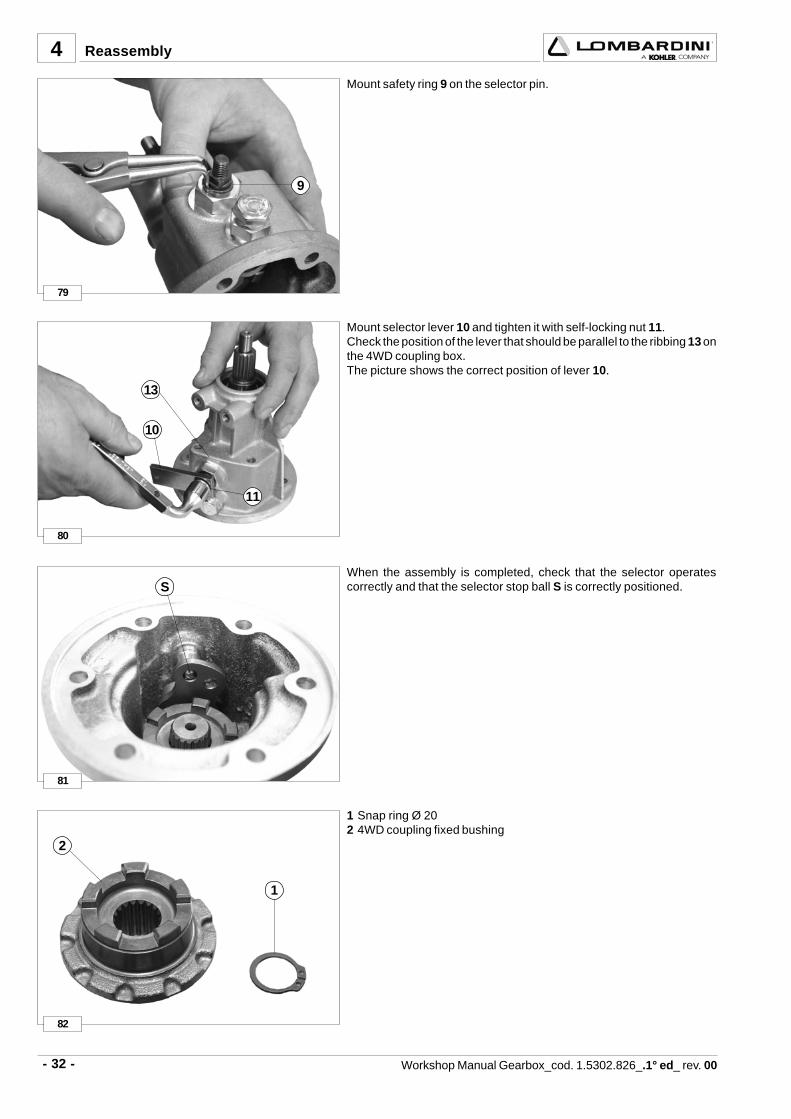
Mount safety ring 9 on the selector pin.
Mount selector lever 10 and tighten it with self-locking nut 11.Check the position of the lever that should be parallel to the ribbing 13 onthe 4WD coupling box.The picture shows the correct position of lever 10.
When the assembly is completed, check that the selector operatescorrectly and that the selector stop ball S is correctly positioned.
1 Snap ring Ø 202 4WD coupling fixed bushing
Reassembly

- 33 -Workshop Manual Gearbox_cod. 1.5302.826_.1° ed_ rev. 0
83
84
86
2
1
85
SR
12
2
1
3
4
Assemble the 4WD coupling fixed bushing 2 on output drive shaft, on theside of the oil drain plug, and lock it with the safety ring 1.Apply Loctite 510 sealant evenly on the support surface of 4WD gearbox.
Oil 4WD coupling selector and mount the 4WD box on the gearbox.
4WD coupling box - Reassembly
ImportantPosition the box on the gearbox being careful to reference (R) ofthe original position.When reassembling the 4WD selector (S) must be disconnected.
Screw the 6 M8 4WD box fastening screws.
1 - 2 M8x1.25 L75 flanged screws.2 - 4 M8x1.25 L25 flanged screws.
Tighten the 6 fastening screws at a torque of 30 Nm.
Odometer (if mounted).
ImportantOnly use ISO Promoblock screws, which are already supplied withthe blocker on the thread.
1 ISO 7380 Promoblock M4x0.7-12 CDQ 10.9 fastening screws.2 Gasket3 Odometer
Reassembly

- 34 - Workshop Manual Gearbox_cod. 1.5302.826_.1° ed_ rev. 00
87
88
89
2
F
E
90
4
Spread the grease as shown in the photo so as to avoid that gasket 2moves.
Make odometer tang E coincide with notch F on the gearbox shaft, asshown in the figure.
Tighten the fastening screws of the odometer.
Remount the gear consent sensors.
Reassembly
Mount the oil seal ring, on the drive output flange side, using the protectionas shown in the figure.
- 35 -Workshop Manual Gearbox_cod. 1.5302.826_.1° ed_ rev. 0
94
1
2
91
92
93
4
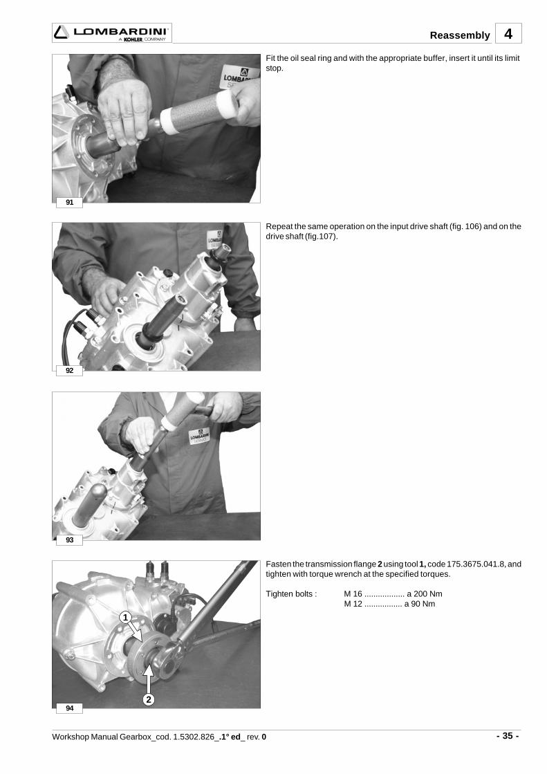
Fasten the transmission flange 2 using tool 1, code 175.3675.041.8, andtighten with torque wrench at the specified torques.
Tighten bolts : M 16 .................. a 200 NmM 12 ................. a 90 Nm
Fit the oil seal ring and with the appropriate buffer, insert it until its limitstop.
Repeat the same operation on the input drive shaft (fig. 106) and on thedrive shaft (fig.107).
Reassembly

- 36 - Workshop Manual Gearbox_cod. 1.5302.826_.1° ed_ rev. 00
C
D
B
E
F
A
5 SPECIAL TOOLS
175.3675.041.8 Transmission Flange Stop
A) 175.8960.028.8 Hitting device for 4 WD drive shaft oil seal
B) 175.8960.029.8 Hitting device for output shaft oil seal
C) 175.8960.030.8 Hitting device for 4WD input shaft oil seal
D) 175.1460.307.8 Hollow punch for input shaft oil seal
E) 175.1460.308.8 Hollow punch for output shaft oil seal
F) 175.1460.309.8 Hollow punch for 4WD drive shaft oil seal
Code and description

- 37 -Workshop Manual Gearbox_cod. 1.5302.826_.1° ed_ rev. 0
. .....................................................................................................................................................
. .....................................................................................................................................................
. .....................................................................................................................................................
. .....................................................................................................................................................
. .....................................................................................................................................................
. .....................................................................................................................................................
. .....................................................................................................................................................
. .....................................................................................................................................................
. .....................................................................................................................................................
. .....................................................................................................................................................
. .....................................................................................................................................................
. .....................................................................................................................................................
. .....................................................................................................................................................
. .....................................................................................................................................................
. .....................................................................................................................................................
. .....................................................................................................................................................
. .....................................................................................................................................................
. .....................................................................................................................................................
. .....................................................................................................................................................
. .....................................................................................................................................................
. .....................................................................................................................................................
. .....................................................................................................................................................
. .....................................................................................................................................................
. .....................................................................................................................................................
. .....................................................................................................................................................
. .....................................................................................................................................................
. .....................................................................................................................................................
. .....................................................................................................................................................

- 38 - Workshop Manual Gearbox_cod. 1.5302.826_.1° ed_ rev. 00
. .....................................................................................................................................................
. .....................................................................................................................................................
. .....................................................................................................................................................
. .....................................................................................................................................................
. .....................................................................................................................................................
. .....................................................................................................................................................
. .....................................................................................................................................................
. .....................................................................................................................................................
. .....................................................................................................................................................
. .....................................................................................................................................................
. .....................................................................................................................................................
. .....................................................................................................................................................
. .....................................................................................................................................................
. .....................................................................................................................................................
. .....................................................................................................................................................
. .....................................................................................................................................................
. .....................................................................................................................................................
. .....................................................................................................................................................
. .....................................................................................................................................................
. .....................................................................................................................................................
. .....................................................................................................................................................
. .....................................................................................................................................................
. .....................................................................................................................................................
. .....................................................................................................................................................
. .....................................................................................................................................................
. .....................................................................................................................................................
. .....................................................................................................................................................
. .....................................................................................................................................................


La Lombardini si riserva il diritto di modificare in qualunque momento i dati contenuti in questa pubblicazione.Lombardini se rèserve le droit de modifier, à n'importe quel moment, les données reportées dans cette publication.
Data reported in this issue can be modified at any time by Lombardini.Lombardini behält sich alle Rechte vor, diese Angabe jederzeit zu verändern.
La Lombardini se reserva el derecho de modificar sin previo aviso los datos de esta publicación.
42100 Reggio Emilia – Italia - ITALYVia Cav. del Lavoro Adelmo Lombardini, 2 - Cas. Post. 1074
Tel. (+39) 0522 3891 - Telex 530003 Motlom I – Telegr.: LombarmotorR.E.A. 227083 - Reg. Impr. RE 10875
Cod. fiscale e Partita IVA 01829970357 - CEE Code IT 01829970357
E-MAIL: [email protected]: http://www.lombardini.it
cod. 1-5302-826
GEARBOX


![[Manual] Lombardini](https://img.pdfslide.us/doc/110x75/544de6e9af7959f7178b4fa3/manual-lombardini.jpg)