Embed Size (px)
Citation preview

GEAR HEAD METAL LATHEMODEL G4002 / G4003
INSTRUCTION MANUAL
COPYRIGHT © 2000 BY GRIZZLY INDUSTRIAL, INC.WARNING: NO PORTION OF THIS MANUAL MAY BE REPRODUCED IN ANY SHAPE
OR FORM WITHOUT THE WRITTEN APPROVAL OF GRIZZLY INDUSTRIAL, INC.REVISED JANUARY, 2000 PRINTED IN CHINA


Table Of ContentsPAGE
1. SAFETYSAFETY RULES FOR POWER TOOLS ..........................................................2-3ADDITIONAL SAFETY INSTRUCTIONS FOR METAL LATHES........................4
2. CIRCUIT REQUIREMENTS220V OPERATION ..............................................................................................5EXTENSION CORDS ..........................................................................................5GROUNDING ......................................................................................................5
3. INTRODUCTIONCOMMENTARY....................................................................................................6UNPACKING ........................................................................................................7PIECE INVENTORY ............................................................................................7CLEAN UP............................................................................................................8SITE CONSIDERATIONS ....................................................................................8
4. ASSEMBLY & SETUPMOUNTING ..........................................................................................................9LUBRICATION ....................................................................................................9CHUCKS ........................................................................................................9-10LIVE CENTER....................................................................................................10STEADY REST ..................................................................................................11FOLLOW REST..................................................................................................114-JAW CHUCK ASSEMBLY ..............................................................................12
5. CONTROLSSPINDLE SPEEDS ............................................................................................13FEED DIRECTION ............................................................................................14SELECTING THE FEED ROD ..........................................................................14QUICK CHANGE SELECTION ..........................................................................15FEED RATE CHART..........................................................................................15THREAD SELECTION ..................................................................................16-19CARRIAGE CONTROLS....................................................................................20TOOLPOST ........................................................................................................21TAILSTOCK CONTROLS ..................................................................................21TEST RUN..........................................................................................................22
6. ADJUSTMENTSGIBS..............................................................................................................23-24STEADY REST/FOLLOW REST........................................................................24TAILSTOCK ..................................................................................................25-26
7. MAINTENANCELUBRICATION ..............................................................................................27-28BEARING PRELOAD ........................................................................................28
8. CLOSURE ................................................................................................................29MACHINE DATA ..........................................................................................................30-31PARTS BREAKDOWN AND PARTS LISTS ................................................................32-49WARRANTY AND RETURNS ............................................................................................50

-2- G4002/3 Gear Head' Lathes
Safety Instructions For Power Tools
SECTION 1: SAFETY
5. KEEP CHILDREN AND VISITORSAWAY. All children and visitors should bekept a safe distance from work area.
6. MAKE WORK SHOP CHILD PROOF withpadlocks, master switches, or by removingstarter keys.
7. DON’T FORCE TOOL. It will do the jobbetter and safer at the rate for which it wasdesigned.
8. USE RIGHT TOOL. Don’t force tool orattachment to do a job for which it was notdesigned.
1. KEEP GUARDS IN PLACE and in workingorder.
2. REMOVE ADJUSTING KEYS ANDWRENCHES. Develop a habit of checkingto see that keys and adjusting wrenchesare removed from tool before turning on.
3. KEEP WORK AREA CLEAN. Clutteredareas and benches invite accidents.
4. DON’T USE IN DANGEROUS ENVIRON-MENT. Don’t use power tools in damp orwet locations, or where any flammable ornoxious fumes may exist. Keep work areawell lighted.
For Your Own Safety Read InstructionManual Before Operating This Equipment
Indicates an imminently hazardous situation which, if notavoided, WILL result in death or serious injury.
Indicates a potentially hazardous situation which, if notavoided, COULD result in death or serious injury.
Indicates a potentially hazardous situation which, if notavoided, MAY result in minor or moderate injury. It may alsobe used to alert against unsafe practices.
This symbol is used to alert the user to useful informationabout proper operation of the equipment.
The purpose of safety symbols is to attract your attention to possible hazardous conditions.This manual uses a series of symbols and signal words which are intended to convey the levelof importance of the safety messages. The progression of symbols is described below.Remember that safety messages by themselves do not eliminate danger and are not a substi-tute for proper accident prevention measures.
NOTICE

G4002/3 Gear Head Lathes -3-
9. USE PROPER EXTENSION CORD. Makesure your extension cord is in good condi-tion. Conductor size should be in accor-dance with the chart below. The amperagerating should be listed on the motor or toolnameplate. An undersized cord will cause adrop in line voltage resulting in loss ofpower and overheating. Your extensioncord must also contain a ground wire andplug pin. Always repair or replace exten-sion cords if they become damaged.
Minimum Gauge for Extension Cords
10. WEAR PROPER APPAREL. Do not wearloose clothing, gloves, neckties, rings,bracelets, or other jewelry which may getcaught in moving parts. Non-slip footwearis recommended. Wear protective hair cov-ering to contain long hair.
11. ALWAYS USE SAFETY GLASSES. Alsouse face or dust mask if cutting operation isdusty. Everyday eyeglasses only haveimpact resistant lenses, they are NOT safe-ty glasses.
12. SECURE WORK. Use clamps or a vise tohold work when practical. It’s safer thanusing your hand and frees both hands tooperate tool.
LENGTHAMP RATING 25ft 50ft 100ft0-6 18 16 167-10 18 16 1411-12 16 16 1413-16 14 12 1217-20 12 12 1021-30 10 10 No
Safety Instructions For Power Tools13. DON’T OVERREACH. Keep proper foot-
ing and balance at all times.
14. MAINTAIN TOOLS WITH CARE. Keeptools sharp and clean for best and safestperformance. Follow instructions for lubri-cating and changing accessories.
15. DISCONNECT TOOLS before servicingand changing accessories, such as blades,bits, cutters, and the like.
16. REDUCE THE RISK OF UNINTENTION-AL STARTING. Make sure switch is in offposition before plugging in.
17. USE RECOMMENDED ACCESSORIES.Consult the owner’s manual for recom-mended accessories. The use of improperaccessories may cause risk of injury.
18. CHECK DAMAGED PARTS. Before fur-ther use of the tool, a guard or other partthat is damaged should be carefullychecked to determine that it will operateproperly and perform its intended function.Check for alignment of moving parts, bind-ing of moving parts, breakage of parts,mounting, and any other conditions thatmay affect its operation. A guard or otherpart that is damaged should be properlyrepaired or replaced.
19. NEVER LEAVE TOOL RUNNING UNAT-TENDED. TURN POWER OFF. Don’tleave tool until it comes to a complete stop.

-4- G4002/3 Gear Head Lathes
Additional Safety Instructions For The Lathe
Like all power tools, there is danger asso-ciated with the Model G4002/3 Metal Lathe.Accidents are frequently caused by lack offamiliarity or failure to pay attention. Usethis tool with respect and caution to lessenthe possibility of operator injury. If normalsafety precautions are overlooked orignored, serious personal injury mayoccur.
1. MAKE SURE ALL GUARDS are in placeand that the lathe sits on a flat, stable sur-face.
2. BEFORE STARTING THE MACHINE becertain the workpiece has been properlyengaged in the chuck and tailstock center(if in use) and that there is adequateclearance for full rotation.
3. ADJUST TOOL HOLDER to provide prop-er support for the turning tool you will beusing. Test tool holder clearance by rotat-ing workpiece by hand before turning latheon.
4. SELECT THE TURNING SPEED which isappropriate for the type of work and thetype of material. Allow the lathe to gain itsfull speed before beginning turning.
5. NEVER CHANGE FEED RATE or spindlespeeds while the lathe is turning.
6. NEVER REVERSE MOTOR DIRECTIONwhile the lathe is running.
7. DO NOT STOP LATHE USING YOURHAND against the workpiece.
8. DO NOT LEAVE LATHE RUNNINGUNATTENDED for any reason.
9. NEVER OPERATE THE LATHE WITHDAMAGED OR WORN PARTS. Maintainyour lathe in proper working condition.Perform routine inspections and mainte-nance promptly when called for. Put awayadjustment tools after use.
10. MAKE SURE YOUR METAL LATHE ISTURNED OFF, disconnected from itspower source and all moving parts havecome to a complete stop before startingany inspection, adjustment, or mainte-nance procedure.
11. KEEP LOOSE CLOTHING ARTICLESsuch as sleeves, belts or jewelry itemsaway from the lathe spindle.
12. ALWAYS USE THE PROPER CUTTINGTOOLS for the material you are turning,make certain they are sharp and that theyare held firmly in the tool holder.
13. ALWAYS PLACE A BOARD OR PIECEOF PLYWOOD ACROSS THE BEDWAYwhen removing or installing chucks toavoid the possibility of a finger pinch pointoccurring between a loose chuck and theedges of the bedway.
No list of safety guidelines can be complete.Every shop environment is different. Alwaysconsider safety first, as it applies to yourindividual working conditions. Use this andother machinery with caution and respect.Failure to do so could result in serious per-sonal injury, damage to equipment or poorwork results.
G4002/3 Gear Head Lathes -5-
220V Operation
SECTION 2: CIRCUIT REQUIREMENTS
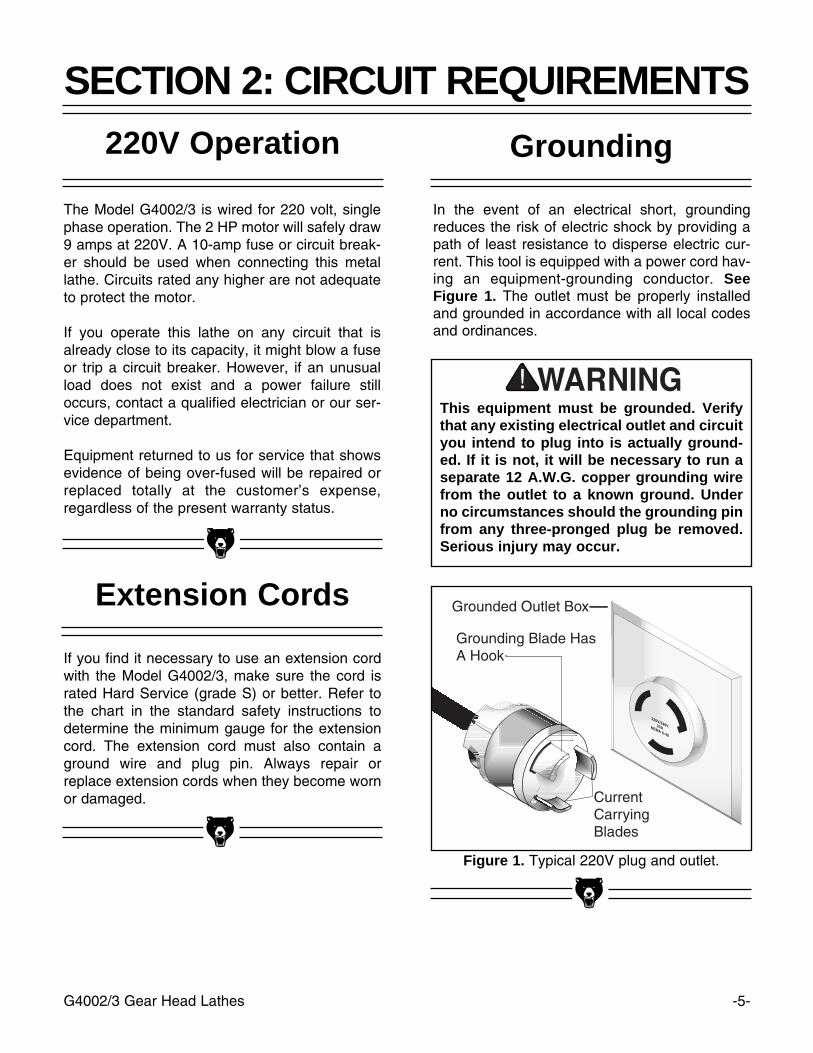
Figure 1. Typical 220V plug and outlet.
Grounding
In the event of an electrical short, groundingreduces the risk of electric shock by providing apath of least resistance to disperse electric cur-rent. This tool is equipped with a power cord hav-ing an equipment-grounding conductor. SeeFigure 1. The outlet must be properly installedand grounded in accordance with all local codesand ordinances.
The Model G4002/3 is wired for 220 volt, singlephase operation. The 2 HP motor will safely draw9 amps at 220V. A 10-amp fuse or circuit break-er should be used when connecting this metallathe. Circuits rated any higher are not adequateto protect the motor.
If you operate this lathe on any circuit that isalready close to its capacity, it might blow a fuseor trip a circuit breaker. However, if an unusualload does not exist and a power failure stilloccurs, contact a qualified electrician or our ser-vice department.
Equipment returned to us for service that showsevidence of being over-fused will be repaired orreplaced totally at the customer’s expense,regardless of the present warranty status.
If you find it necessary to use an extension cordwith the Model G4002/3, make sure the cord israted Hard Service (grade S) or better. Refer tothe chart in the standard safety instructions todetermine the minimum gauge for the extensioncord. The extension cord must also contain aground wire and plug pin. Always repair orreplace extension cords when they become wornor damaged.
Extension Cords
This equipment must be grounded. Verifythat any existing electrical outlet and circuityou intend to plug into is actually ground-ed. If it is not, it will be necessary to run aseparate 12 A.W.G. copper grounding wirefrom the outlet to a known ground. Underno circumstances should the grounding pinfrom any three-pronged plug be removed.Serious injury may occur.
-6- G4002/3 Gear Head Lathes
Commentary
We are proud to offer the Grizzly Model G4002 /G4003 Gear Head Metal Lathe. The ModelG4002 / G4003 is part of a growing Grizzly fami-ly of fine metalworking machinery. When usedaccording to the guidelines set forth in this man-ual, you can expect years of trouble-free, enjoy-able operation and proof of Grizzly’s commitment to customer satisfaction.
The Model G4002/3 is a precision metalworkinglathe. It features cast iron construction, 24" or 36"V-bed, a speed range of 70-1,400 RPM, 9-speedgearbox and a complete electrical package. Theelectrical package consists of a 2 H.P., 110V /220V motor, electro-magnetic motor control andoverload protection. We also offer many acces-sories for this lathe. Please refer to the latestGrizzly catalog for prices and information.
We are also pleased to provide this instructionalmanual with the Model G4002 / G4003 Lathe.This manual was written to guide you throughassembly, review safety considerations andcover basic operating procedures. It representsour latest effort to produce the best documenta-tion possible. If you have any constructive criti-cisms or comments you feel we should include inour next printing, please write us at the addressbelow.
Grizzly Industrial, Inc.C/O Technical Documentation
P.O. Box 2069Bellingham, WA 98227-2069
Most importantly, we stand behind our machines.If you have any service questions or partsrequests, please call or write us at the locationlisted below.
Grizzly Industrial, Inc.1203 Lycoming Mall Circle
Muncy, PA 17756Phone: (570) 546-9663
Fax: (800) 438-5901E-Mail: [email protected] Site: http://www.grizzly.com
The specifications, drawings, and photographsillustrated in this manual represent the ModelG4002/3 as supplied when the manual was pre-pared. However, owing to Grizzly’s policy of con-tinuous improvement, changes may be made atany time with no obligation on the part of Grizzly.Whenever possible, though, we send manualupdates to all owners of a particular tool ormachine. Should you receive one, we urge you toinsert the new information with the old and keepit for reference.
To operate this, or any power tool, safelyand efficiently, it is essential to become asfamiliar with its characteristics as possible.The time you invest before you begin to useyour Model G4002/3 will be time well spent.DO NOT operate this machine until you arecompletely familiar with the contents of thismanual. Make sure you read and under-stand all of the safety procedures. If you donot understand something, DO NOT operatethe machine.
SECTION 3: INTRODUCTION

G4002/3 Gear Head Lathes -7-
Unpacking
This Metal Lathe is shipped from the manufactur-er in a carefully packed crate. If you discover themachine is damaged after you’ve signed for deliv-ery, and the truck and driver are gone, you willneed to file a freight claim with the carrier. Savethe containers and all packing materials for pos-sible inspection by the carrier or its agent.Without the packing materials, filing a freightclaim can be difficult. If you need assistancedetermining whether you need to file a freightclaim, or with the procedure to file one, pleasecontact our Customer Service.
When you are completely satisfied with the con-dition of your shipment, you should inventory itsparts.
The G4002 and G4003 are heavy machines(1015 lbs. and 1040 lbs. shipping weight). DONOT over-exert yourself while unpacking ormoving your machine – get assistance. In theevent that your Metal Lathe must be moved upor down a flight of stairs, be sure that the stairsare capable of supporting the combined weightof people and the machine. Serious personalinjury may occur.
Piece Inventory
The Model G4002/3 is, for the most part, pre-assembled at the factory. Inside the crate you’llfind:
• The Model G4002/3 Metal Lathe• 6" 3-jaw Chuck• 8" 4-jaw Chuck• Face Plate• Steady Rest• Follow Rest• Quick Change Tool Post• Tool Holder• Toolbox • Metric Allen® Wrenches• Straight Blade Screwdriver• Phillips® Screwdriver• Oil can• 26T Gear • 27T Gear • 35T Gear • 2- 40T Gear • 45T Gear • 50T Gear• Chuck wrenches (2)• Reverse Jaws for the 3-Jaw Chuck• Dead Center - MT #3• Live Center - MT #3
In the event that any non-proprietary parts aremissing (e.g. a nut or a washer), we would beglad to replace them, or, for the sake of expedi-ency, replacements can be obtained at your localhardware store.
-8- G4002/3 Gear Head Lathes
Site Considerations
1. Floor Load: The Model G4002/3 can bemounted on your existing workbench or onan optional cabinet stand which is listed inour current Grizzly catalog. If you choose touse the stand, you will find the holes for bolt-ing the G4002/3 to the stand are already inplace. If you are using your own bench,ensure that it is strong enough to handle theweight of the G4002/3 lathe. Keep in mind,whichever way you choose to mount thelathe, it’s essential that the mounting surfacebe perfectly flat. Use an accurate carpenter’slevel to ensure that your bench is properlyleveled.
2. Working Clearances: Consider existing andanticipated needs, size of material to beprocessed through each machine, andspace for auxiliary stands, work tables orother machinery when establishing a loca-tion for your lathe.
3. Lighting and Outlets: Lighting should bebright enough to eliminate shadow and pre-vent eye strain. Electrical circuits should bededicated or large enough to handle amper-age requirements. Outlets should be locatednear each machine so power or extensioncords are clear of high-traffic areas. Observelocal electrical codes for proper installationof new lighting, outlets, or circuits.
Clean Up
The unpainted surfaces are coated with a waxyoil to protect them from corrosion during ship-ment. Remove this protective coating with a sol-vent cleaner or citrus-based degreaser, likeGrizzly’s G7895 Citrus Engine Degreaser. Avoidchlorine-based solvents as they may damagepainted surfaces should they come in contact.Always follow the usage instructions on the prod-uct you choose for clean up.
Many of the solvents commonly used toclean machinery can be highly flammable,and toxic when inhaled or ingested. Alwayswork in well-ventilated areas far frompotential ignition sources when dealingwith solvents. Use care when disposing ofwaste rags and towels to be sure they donot create fire or environmental hazards.Keep children and animals safely awaywhen cleaning and assembling thismachine.
Do not use gasoline or other petroleum-based solvents to remove this protectivecoating. These products generally have lowflash points which makes them extremelyflammable. A risk of explosion and burningexists if these products are used. Seriouspersonal injury may occur.
All die-cut metal parts have a sharp edge(called “flashing”) on them after they areformed. This is generally removed at thefactory. Sometimes a bit of flashing mightescape inspection, and the sharp edge maycause cuts or lacerations when handled.Please examine the edges of all die-cutmetal parts and file or sand the edge toremove the flashing before handling.
Make your shop “child safe”. Ensure thatyour workplace is inaccessible to young-sters by closing and locking all entranceswhen you are away. Never allow visitors inyour shop when assembling, adjusting oroperating equipment.
G4002/3 Gear Head Lathes -9-
Chucks
The Model G4002/3 Metal Lathe comes equippedwith a 6'' 3-jaw chuck (already installed), a 8'' 4-jaw chuck and a face plate.
The 3-jaw chuck is a scroll-type chuck, meaningthat all three jaws move in unison when adjust-ments are made. The 4-jaw chuck, on the otherhand, features independent jaws. The 4-jawchuck is used for square or unevenly-shapedstock.
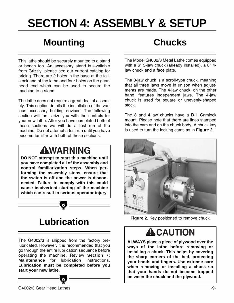
The 3 and 4-jaw chucks have a D-1 Camlockmount. Please note that there are lines stampedinto the cam and on the chuck body. A chuck keyis used to turn the locking cams as in Figure 2.
Mounting
This lathe should be securely mounted to a standor bench top. An accessory stand is availablefrom Grizzly, please see our current catalog forpricing. There are 2 holes in the base at the tail-stock end of the lathe and four holes on the gear-head end which can be used to secure themachine to a stand.
The lathe does not require a great deal of assem-bly. This section details the installation of the var-ious accessory holding devices. The followingsection will familiarize you with the controls foryour new lathe. After you have completed both ofthese sections we will do a test run of themachine. Do not attempt a test run until you havebecome familiar with both of these sections.
SECTION 4: ASSEMBLY & SETUP
DO NOT attempt to start this machine untilyou have completed all of the assembly andcontrol familiarization steps. When per-forming the assembly steps, ensure thatthe switch is off and the power is discon-nected. Failure to comply with this couldcause inadvertent starting of the machinewhich can result in serious operator injury.
Lubrication
The G4002/3 is shipped from the factory pre-lubricated. However, it is recommended that yougo through the entire lubrication sequence beforeoperating the machine. Review Section 7:Maintenance for lubrication instructions.Lubrication must be completed before youstart your new lathe.
Figure 2. Key positioned to remove chuck.
ALWAYS place a piece of plywood over theways of the lathe before removing orinstalling a chuck. This helps by coveringthe sharp corners of the bed, protectingyour hands and fingers. Use extreme carewhen removing or installing a chuck sothat your hands do not become trappedbetween the chuck and the plywood.
-10- G4002/3 Gear Head Lathes
To remove a chuck:
1. Place a piece of plywood across the lathebed and position it just under the chuck.The board should be at least 8" wide and10" long.
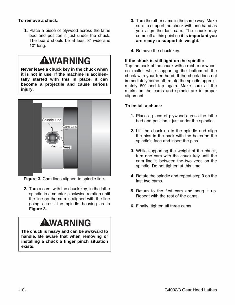
2. Turn a cam, with the chuck key, in the lathespindle in a counter-clockwise rotation untilthe line on the cam is aligned with the linegoing across the spindle housing as inFigure 3.
Figure 3. Cam lines aligned to spindle line.
Never leave a chuck key in the chuck whenit is not in use. If the machine is acciden-tally started with this in place, it canbecome a projectile and cause seriousinjury.
The chuck is heavy and can be awkward tohandle. Be aware that when removing orinstalling a chuck a finger pinch situationexists.
3. Turn the other cams in the same way. Makesure to support the chuck with one hand asyou align the last cam. The chuck maycome off at this point so it is important youare ready to support its weight.
4. Remove the chuck key.
If the chuck is still tight on the spindle:Tap the back of the chuck with a rubber or wood-en mallet while supporting the bottom of thechuck with your free hand. If the chuck does notimmediately come off, rotate the spindle approxi-mately 60˚ and tap again. Make sure all themarks on the cams and spindle are in properalignment.
To install a chuck:
1. Place a piece of plywood across the lathebed and position it just under the spindle.
2. Lift the chuck up to the spindle and alignthe pins in the back with the holes on thespindle’s face and insert the pins.
3. While supporting the weight of the chuck,turn one cam with the chuck key until thecam line is between the two vees on thespindle. Do not tighten at this time.
4. Rotate the spindle and repeat step 3 on thelast two cams.
5. Return to the first cam and snug it up.Repeat with the rest of the cams.
6. Finally, tighten all three cams.
G4002/3 Gear Head Lathes -11-
Live Center
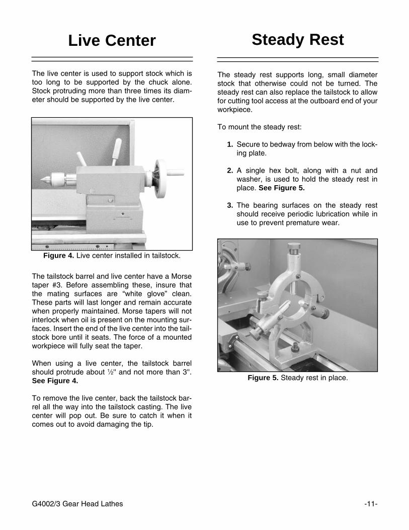
The live center is used to support stock which istoo long to be supported by the chuck alone.Stock protruding more than three times its diam-eter should be supported by the live center.
Figure 4. Live center installed in tailstock.
Figure 5. Steady rest in place.
Steady Rest
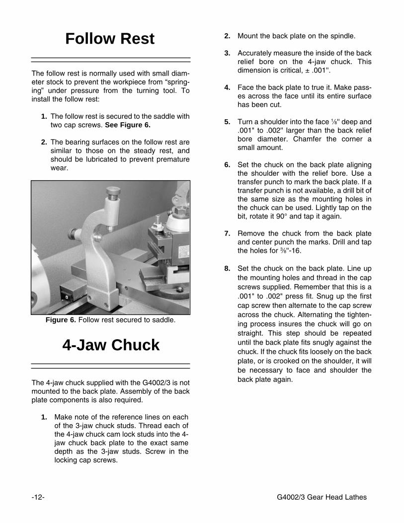
The steady rest supports long, small diameterstock that otherwise could not be turned. Thesteady rest can also replace the tailstock to allowfor cutting tool access at the outboard end of yourworkpiece.
To mount the steady rest:
1. Secure to bedway from below with the lock-ing plate.
2. A single hex bolt, along with a nut andwasher, is used to hold the steady rest inplace. See Figure 5.
3. The bearing surfaces on the steady restshould receive periodic lubrication while inuse to prevent premature wear.
The tailstock barrel and live center have a Morsetaper #3. Before assembling these, insure thatthe mating surfaces are “white glove” clean.These parts will last longer and remain accuratewhen properly maintained. Morse tapers will notinterlock when oil is present on the mounting sur-faces. Insert the end of the live center into the tail-stock bore until it seats. The force of a mountedworkpiece will fully seat the taper.
When using a live center, the tailstock barrelshould protrude about 1⁄2'' and not more than 3''.See Figure 4.
To remove the live center, back the tailstock bar-rel all the way into the tailstock casting. The livecenter will pop out. Be sure to catch it when itcomes out to avoid damaging the tip.
-12- G4002/3 Gear Head Lathes
4-Jaw Chuck
The 4-jaw chuck supplied with the G4002/3 is notmounted to the back plate. Assembly of the backplate components is also required.
1. Make note of the reference lines on eachof the 3-jaw chuck studs. Thread each ofthe 4-jaw chuck cam lock studs into the 4-jaw chuck back plate to the exact samedepth as the 3-jaw studs. Screw in thelocking cap screws.
2. Mount the back plate on the spindle.
3. Accurately measure the inside of the backrelief bore on the 4-jaw chuck. Thisdimension is critical, ± .001''.
4. Face the back plate to true it. Make pass-es across the face until its entire surfacehas been cut.
5. Turn a shoulder into the face 1⁄8'' deep and.001" to .002'' larger than the back reliefbore diameter. Chamfer the corner asmall amount.
6. Set the chuck on the back plate aligningthe shoulder with the relief bore. Use atransfer punch to mark the back plate. If atransfer punch is not available, a drill bit ofthe same size as the mounting holes inthe chuck can be used. Lightly tap on thebit, rotate it 90° and tap it again.
7. Remove the chuck from the back plateand center punch the marks. Drill and tapthe holes for 3⁄8''-16.
8. Set the chuck on the back plate. Line upthe mounting holes and thread in the capscrews supplied. Remember that this is a.001" to .002" press fit. Snug up the firstcap screw then alternate to the cap screwacross the chuck. Alternating the tighten-ing process insures the chuck will go onstraight. This step should be repeateduntil the back plate fits snugly against thechuck. If the chuck fits loosely on the backplate, or is crooked on the shoulder, it willbe necessary to face and shoulder theback plate again.
The follow rest is normally used with small diam-eter stock to prevent the workpiece from “spring-ing” under pressure from the turning tool. Toinstall the follow rest:
1. The follow rest is secured to the saddle withtwo cap screws. See Figure 6.
2. The bearing surfaces on the follow rest aresimilar to those on the steady rest, andshould be lubricated to prevent prematurewear.
Figure 6. Follow rest secured to saddle.
Follow Rest
G4002/3 Gear Head Lathes -13-
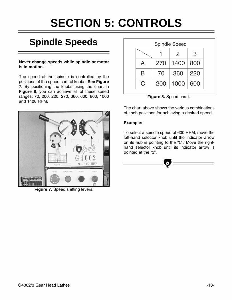
Spindle Speeds
SECTION 5: CONTROLS
Figure 7. Speed shifting levers.
Figure 8. Speed chart.
Never change speeds while spindle or motoris in motion.
The speed of the spindle is controlled by thepositions of the speed control knobs. See Figure7. By positioning the knobs using the chart inFigure 8, you can achieve all of these speedranges: 70, 200, 220, 270, 360, 600, 800, 1000and 1400 RPM.
The chart above shows the various combinationsof knob positions for achieving a desired speed.
Example:
To select a spindle speed of 600 RPM, move theleft-hand selector knob until the indicator arrowon its hub is pointing to the “C”. Move the right-hand selector knob until its indicator arrow ispointed at the “3”.
Quick Change Selection
The two levers at the bottom of the headstockchange the feed rate, or the number of threads-per-inch. This section of the machine is com-monly known as the Quick Change Gear Box.See Figure 11. The left-hand lever can beengaged in any of five different positions and arelisted on the charts as A, B, C, D, and E. Theright-hand lever has 8 positions and are listed onthe charts as 1 through 8.
The machine label describes some of the moretypical settings which might be used. Figure 12shows the feed rate chart located on the gearcover of the lathe. The chart is divided into met-ric feed rates and inch feed rates.
-14- G4002/3 Gear Head Lathes
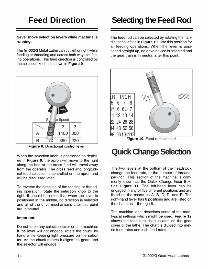
Figure 9. Directional control lever.
Feed Direction Selecting the Feed Rod
Never move selection levers while machine isrunning.
The G4002/3 Metal Lathe can cut left or right whilefeeding or threading and across both ways for fac-ing operations. This feed direction is controlled bythe selection knob as shown in Figure 9.
When the selection knob is positioned as depict-ed in Figure 9, the apron will move to the rightalong the bed or the cross feed will travel awayfrom the operator. The cross feed and longitudi-nal feed selection is controlled on the apron andwill be discussed later.
To reverse the direction of the feeding or thread-ing operation, rotate the selection knob to theright. It should be noted that when the lever ispositioned in the middle, no direction is selectedand all of the drive mechanisms after this pointare in neutral.
Important:
Do not force any selection lever on the machine.If the lever will not engage, rotate the chuck byhand while keeping light pressure on the selec-tor. As the chuck rotates it aligns the gears andthe selector will engage.
Figure 10. Feed rod selected.
The feed rod can be selected by rotating the han-dle to the left as in Figure 10. Use this position forall feeding operations. When the lever is posi-tioned straight up, no drive device is selected andthe gear train is in neutral after this point.
G4002/3 Gear Head Lathes -15-
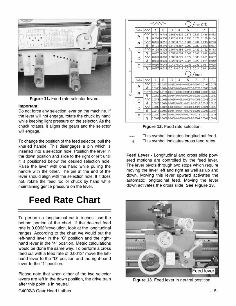
Feed Rate Chart
Figure 11. Feed rate selector levers.
Figure 12. Feed rate selection.
This symbol indicates longitudinal feed.This symbol indicates cross feed rates.
Important:Do not force any selection lever on the machine. Ifthe lever will not engage, rotate the chuck by handwhile keeping light pressure on the selector. As thechuck rotates, it aligns the gears and the selectorwill engage.
To change the position of the feed selector, pull theknurled handle. This disengages a pin which isinserted into a selection hole. Position the lever inthe down position and slide to the right or left untilit is positioned below the desired selection hole.Raise the lever with one hand while pulling thehandle with the other. The pin at the end of thelever should align with the selection hole. If it doesnot, rotate the feed rod or chuck by hand whilemaintaining gentle pressure on the lever.
Feed Lever - Longitudinal and cross slide pow-ered motions are controlled by the feed lever.The lever pivots through two stops which requiremoving the lever left and right as well as up anddown. Moving this lever upward activates theautomatic longitudinal feed. Moving the leverdown activates the cross slide. See Figure 13.
To perform a longitudinal cut in inches, use thebottom portion of the chart. If the desired feedrate is 0.0062"/revolution, look at the longitudinalranges. According to the chart we would put theleft-hand lever in the “C” position and the right-hand lever in the “4” position. Metric calculationswould be done the same way. To perform a crossfeed cut with a feed rate of 0.0013" move the left-hand lever to the “D” position and the right-handlever to the “1” position.
Please note that when either of the two selectorlevers are left in the down position, the drive trainafter this point is in neutral.
Figure 13. Feed lever in neutral postition.
Feed lever
-16- G4002/3 Gear Head Lathes
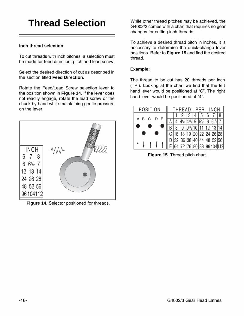
Figure 14. Selector positioned for threads.
Figure 15. Thread pitch chart.
Inch thread selection:
To cut threads with inch pitches, a selection mustbe made for feed direction, pitch and lead screw.
Select the desired direction of cut as described inthe section titled Feed Direction.
Rotate the Feed/Lead Screw selection lever tothe position shown in Figure 14. If the lever doesnot readily engage, rotate the lead screw or thechuck by hand while maintaining gentle pressureon the lever.
While other thread pitches may be achieved, theG4002/3 comes with a chart that requires no gearchanges for cutting inch threads.
To achieve a desired thread pitch in inches, it isnecessary to determine the quick-change leverpositions. Refer to Figure 15 and find the desiredthread.
Thread Selection
Example:
The thread to be cut has 20 threads per inch(TPI). Looking at the chart we find that the lefthand lever would be positioned at “C”. The righthand lever would be positioned at “4”.
-17-G4002/3 Gear Head Lathes
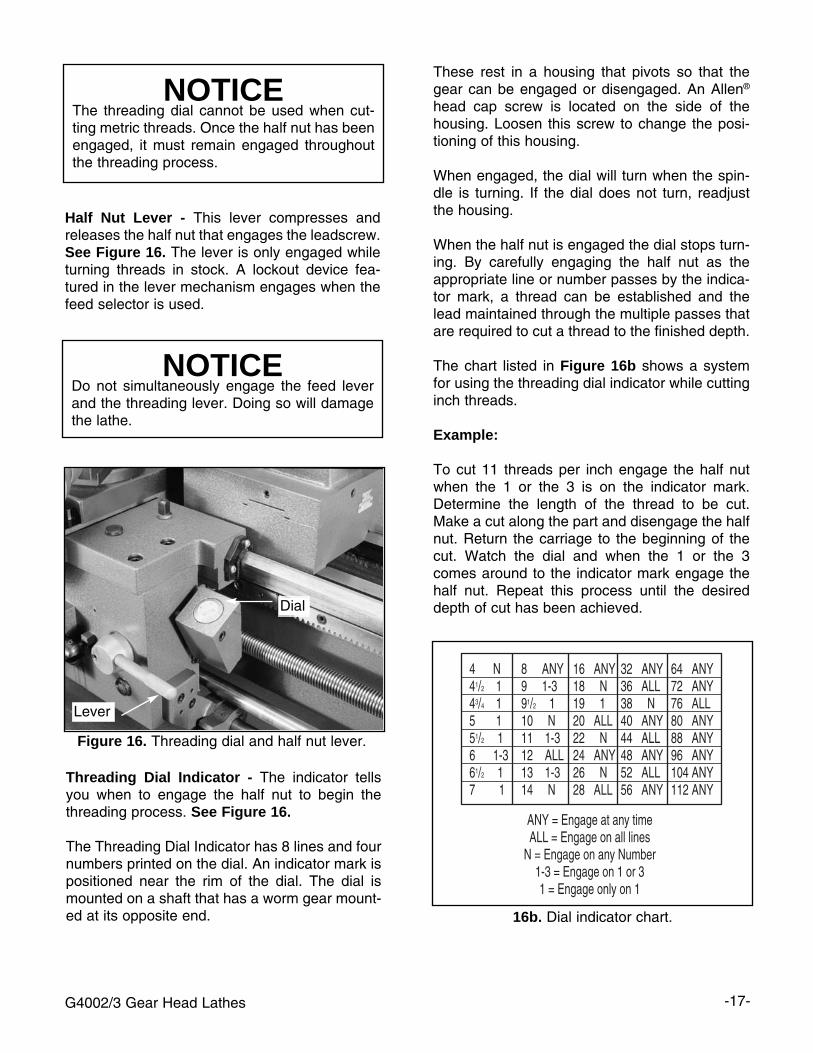
Half Nut Lever - This lever compresses andreleases the half nut that engages the leadscrew.See Figure 16. The lever is only engaged whileturning threads in stock. A lockout device fea-tured in the lever mechanism engages when thefeed selector is used.
Threading Dial Indicator - The indicator tellsyou when to engage the half nut to begin thethreading process. See Figure 16.
The Threading Dial Indicator has 8 lines and fournumbers printed on the dial. An indicator mark ispositioned near the rim of the dial. The dial ismounted on a shaft that has a worm gear mount-ed at its opposite end.
Figure 16. Threading dial and half nut lever.
NOTICEDo not simultaneously engage the feed leverand the threading lever. Doing so will damagethe lathe.
NOTICEThe threading dial cannot be used when cut-ting metric threads. Once the half nut has beenengaged, it must remain engaged throughoutthe threading process.
16b. Dial indicator chart.
Lever
Dial
These rest in a housing that pivots so that thegear can be engaged or disengaged. An Allen®
head cap screw is located on the side of thehousing. Loosen this screw to change the posi-tioning of this housing.
When engaged, the dial will turn when the spin-dle is turning. If the dial does not turn, readjustthe housing.
When the half nut is engaged the dial stops turn-ing. By carefully engaging the half nut as theappropriate line or number passes by the indica-tor mark, a thread can be established and thelead maintained through the multiple passes thatare required to cut a thread to the finished depth.
The chart listed in Figure 16b shows a systemfor using the threading dial indicator while cuttinginch threads.
Example:
To cut 11 threads per inch engage the half nutwhen the 1 or the 3 is on the indicator mark.Determine the length of the thread to be cut.Make a cut along the part and disengage the halfnut. Return the carriage to the beginning of thecut. Watch the dial and when the 1 or the 3comes around to the indicator mark engage thehalf nut. Repeat this process until the desireddepth of cut has been achieved.
-18- G4002/3 Gear Head Lathes
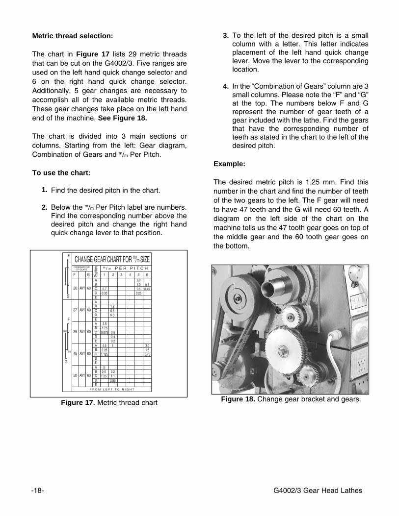
3. To the left of the desired pitch is a smallcolumn with a letter. This letter indicatesplacement of the left hand quick changelever. Move the lever to the correspondinglocation.
4. In the “Combination of Gears” column are 3small columns. Please note the “F” and “G”at the top. The numbers below F and Grepresent the number of gear teeth of agear included with the lathe. Find the gearsthat have the corresponding number ofteeth as stated in the chart to the left of thedesired pitch.
Example:
The desired metric pitch is 1.25 mm. Find thisnumber in the chart and find the number of teethof the two gears to the left. The F gear will needto have 47 teeth and the G will need 60 teeth. Adiagram on the left side of the chart on themachine tells us the 47 tooth gear goes on top ofthe middle gear and the 60 tooth gear goes onthe bottom.
Metric thread selection:
The chart in Figure 17 lists 29 metric threadsthat can be cut on the G4002/3. Five ranges areused on the left hand quick change selector and6 on the right hand quick change selector.Additionally, 5 gear changes are necessary toaccomplish all of the available metric threads.These gear changes take place on the left handend of the machine. See Figure 18.
The chart is divided into 3 main sections orcolumns. Starting from the left: Gear diagram,Combination of Gears and m/m Per Pitch.
To use the chart:
1. Find the desired pitch in the chart.
2. Below the m/m Per Pitch label are numbers.Find the corresponding number above thedesired pitch and change the right handquick change lever to that position.
Figure 17. Metric thread chart Figure 18. Change gear bracket and gears.
G4002/3 Gear Head Lathes -19-
Thread Selection Cont.
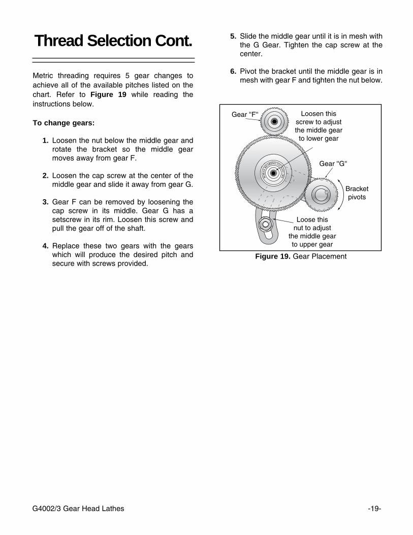
Metric threading requires 5 gear changes toachieve all of the available pitches listed on thechart. Refer to Figure 19 while reading theinstructions below.
To change gears:
1. Loosen the nut below the middle gear androtate the bracket so the middle gearmoves away from gear F.
2. Loosen the cap screw at the center of themiddle gear and slide it away from gear G.
3. Gear F can be removed by loosening thecap screw in its middle. Gear G has asetscrew in its rim. Loosen this screw andpull the gear off of the shaft.
4. Replace these two gears with the gearswhich will produce the desired pitch andsecure with screws provided.
Figure 19. Gear Placement
5. Slide the middle gear until it is in mesh with the G Gear. Tighten the cap screw at thecenter.
6. Pivot the bracket until the middle gear is inmesh with gear F and tighten the nut below.
-20- G4002/3 Gear Head Lathes
Figure 21. Spindle rotation control lever.
Spindle rotation control - The spindle rotation iscontrolled from the lever on the right hand side ofthe carriage. Moving the lever down causes thespindle to rotate counter clockwise. Moving thelever up causes the spindle to turn clockwise. Themiddle position stops the motor and the lever isconsidered to be in a neutral position. See Figure21.
Figure 20. Handwheel locations.
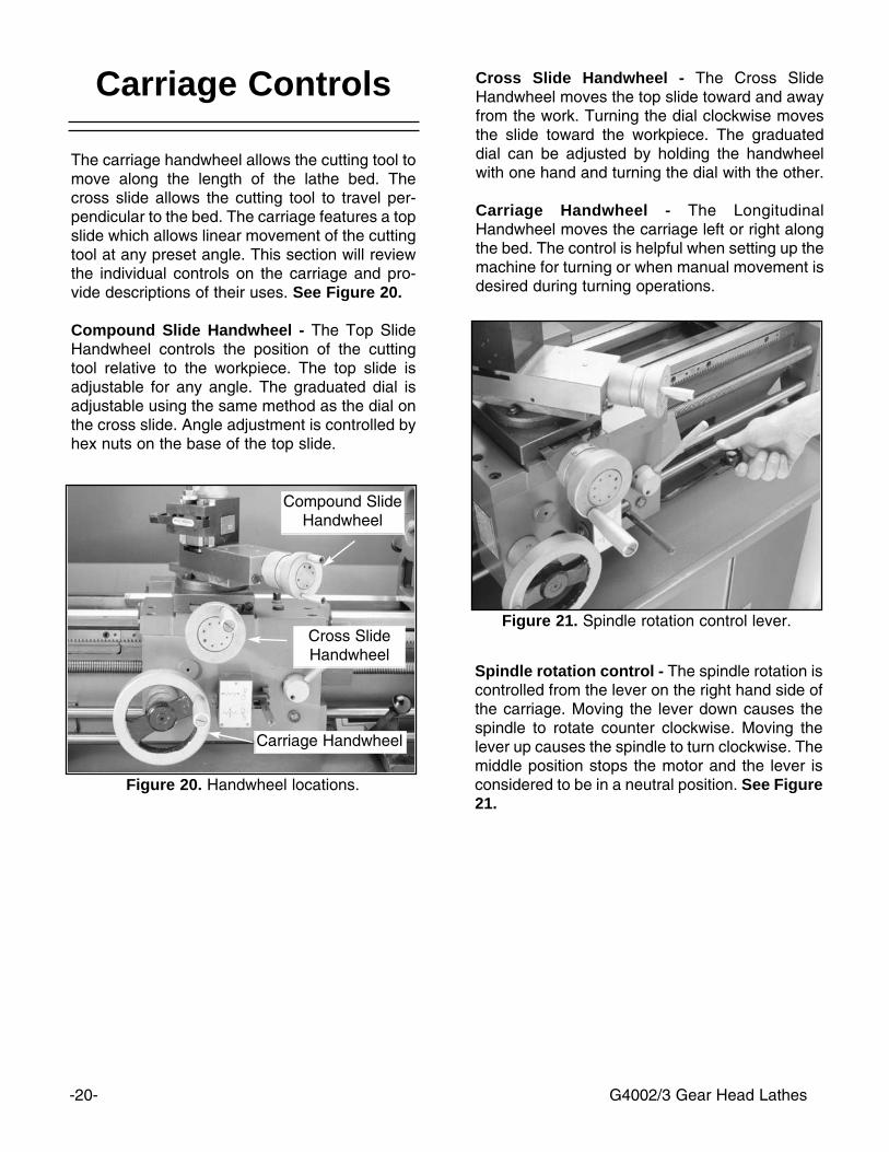
Carriage Controls
The carriage handwheel allows the cutting tool tomove along the length of the lathe bed. Thecross slide allows the cutting tool to travel per-pendicular to the bed. The carriage features a topslide which allows linear movement of the cuttingtool at any preset angle. This section will reviewthe individual controls on the carriage and pro-vide descriptions of their uses. See Figure 20.
Compound Slide Handwheel - The Top SlideHandwheel controls the position of the cuttingtool relative to the workpiece. The top slide isadjustable for any angle. The graduated dial isadjustable using the same method as the dial onthe cross slide. Angle adjustment is controlled byhex nuts on the base of the top slide.
Cross Slide Handwheel - The Cross SlideHandwheel moves the top slide toward and awayfrom the work. Turning the dial clockwise movesthe slide toward the workpiece. The graduateddial can be adjusted by holding the handwheelwith one hand and turning the dial with the other.
Carriage Handwheel - The LongitudinalHandwheel moves the carriage left or right alongthe bed. The control is helpful when setting up themachine for turning or when manual movement isdesired during turning operations.
Carriage Handwheel
Cross SlideHandwheel
Compound SlideHandwheel
G4002/3 Gear Head Lathes -21-
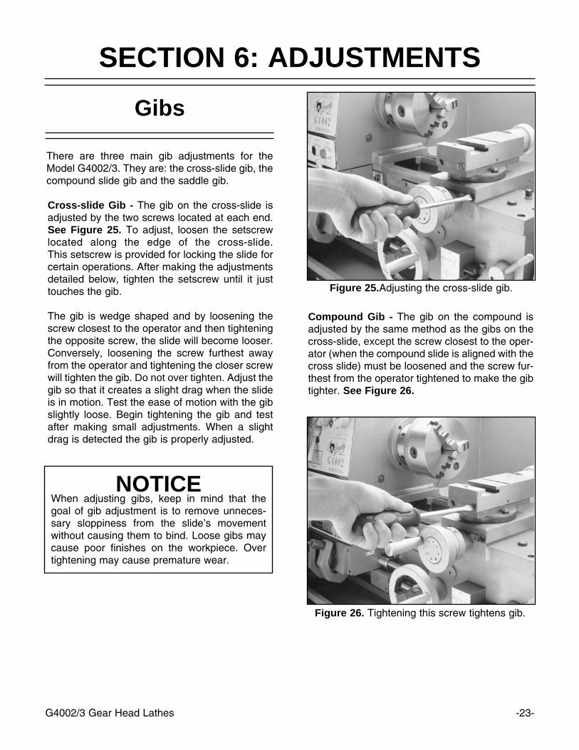
Figure 23. Detail of tailstock controls.
Tailstock ControlsTool Post and Holder
The tailstock serves many functions. The prima-ry use is for holding centers and drill chucks. Thebarrel has a Morse taper #3 bore and is imprintedwith graduations in millimeters and inches.Please refer to Figure 23.
Tailstock Handwheel - Turning the handwheeladvances or retracts the barrel in the tailstock.The graduated dial on the handwheel isadjustable.
Top Lock Lever - This lever locks the tailstockbarrel in place.
Side Lock Lever - This lever locks the tailstockin place on the lathe bed.
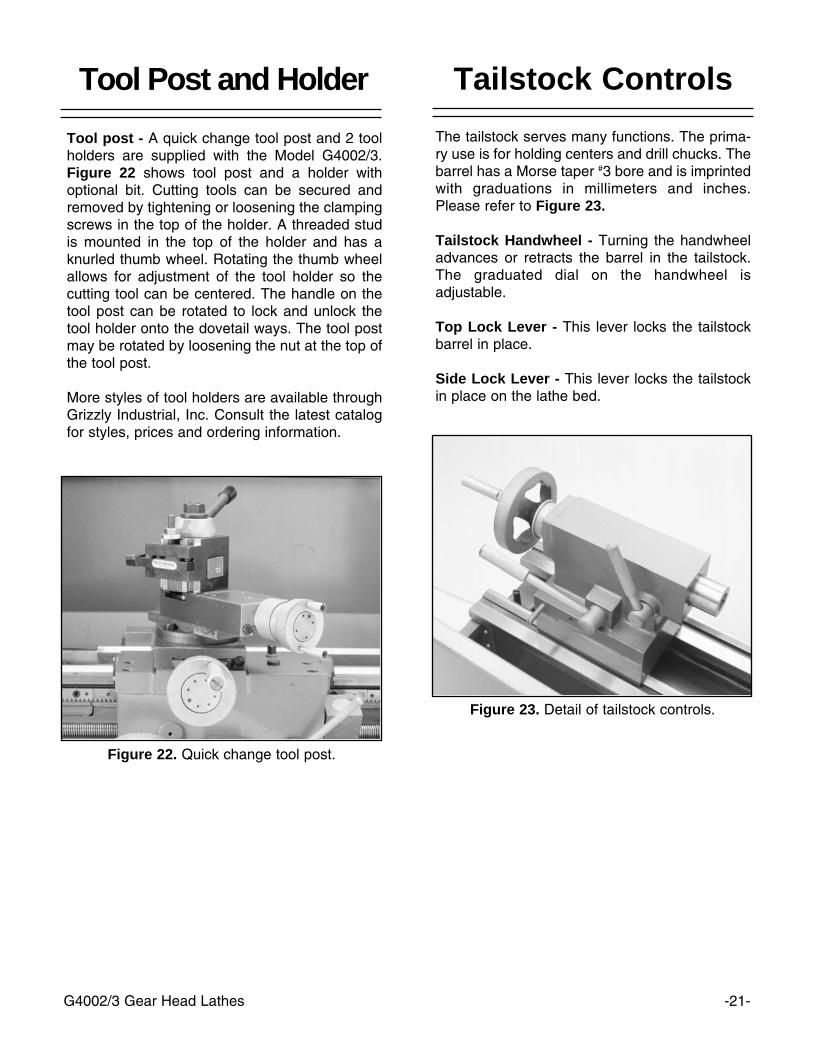
Figure 22. Quick change tool post.
Tool post - A quick change tool post and 2 toolholders are supplied with the Model G4002/3.Figure 22 shows tool post and a holder withoptional bit. Cutting tools can be secured andremoved by tightening or loosening the clampingscrews in the top of the holder. A threaded studis mounted in the top of the holder and has aknurled thumb wheel. Rotating the thumb wheelallows for adjustment of the tool holder so thecutting tool can be centered. The handle on thetool post can be rotated to lock and unlock thetool holder onto the dovetail ways. The tool postmay be rotated by loosening the nut at the top ofthe tool post.
More styles of tool holders are available throughGrizzly Industrial, Inc. Consult the latest catalogfor styles, prices and ordering information.

-22- G4002/3 Gear Head Lathes
Test Run
Now that the lathe is securely in place andyou’ve read the safety guidelines, it’s time to givethe machine a test run.
Before starting the machine:
1. Make sure the machine is properly ground-ed, the Power Switch is in the “OFF” positionand the spindle control lever is in the neutralposition. See Figure 24.
2. Inspect the machine to ensure that all handtools are out of the way, guards are in placeand nothing is impeding the movement ofthe chuck. Check this by rotating the chuckby hand.
3. Rotate the stop switch, on the headstock ofthe lathe, in the direction indicated by thearrows imprinted on the button.
4. Lower the control lever on the apron. Thespindle should start turning in a counterclockwise direction.
Figure 24. Carriage control lever in neutral.
Always make sure the power switch is in the“OFF” position and the spindle control leveris in the neutral position before plugging inpower cord.
If the direction is reversed, contact our service depart-ment for further instructions.
5. If the lathe is running correctly, lift the spindle con-trol lever to the neutral position, wait for themachine to come to a complete stop and takesome time to become familiar with the variouscontrols.
G4002/3 Gear Head Lathes -23-
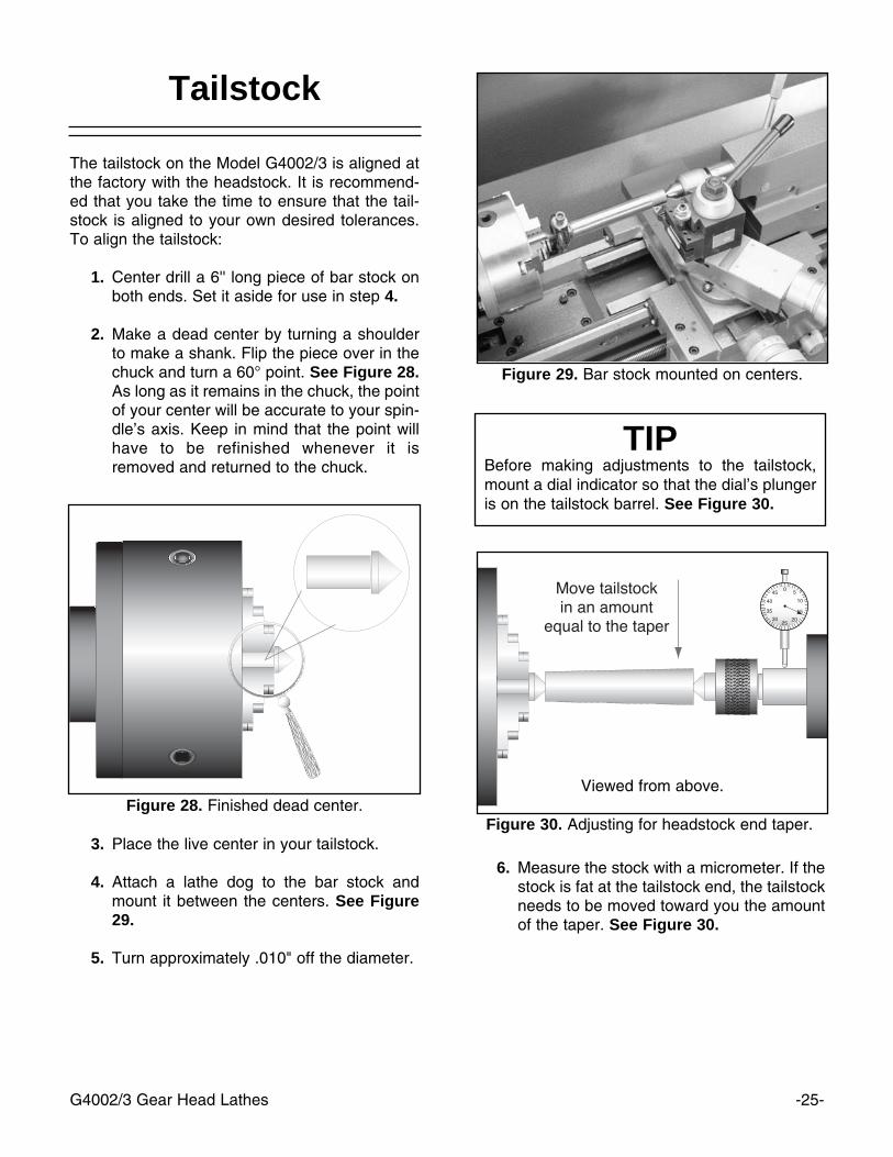
Compound Gib - The gib on the compound isadjusted by the same method as the gibs on thecross-slide, except the screw closest to the oper-ator (when the compound slide is aligned with thecross slide) must be loosened and the screw fur-thest from the operator tightened to make the gibtighter. See Figure 26.
Figure 26. Tightening this screw tightens gib.
NOTICEWhen adjusting gibs, keep in mind that thegoal of gib adjustment is to remove unneces-sary sloppiness from the slide’s movementwithout causing them to bind. Loose gibs maycause poor finishes on the workpiece. Overtightening may cause premature wear.
SECTION 6: ADJUSTMENTS
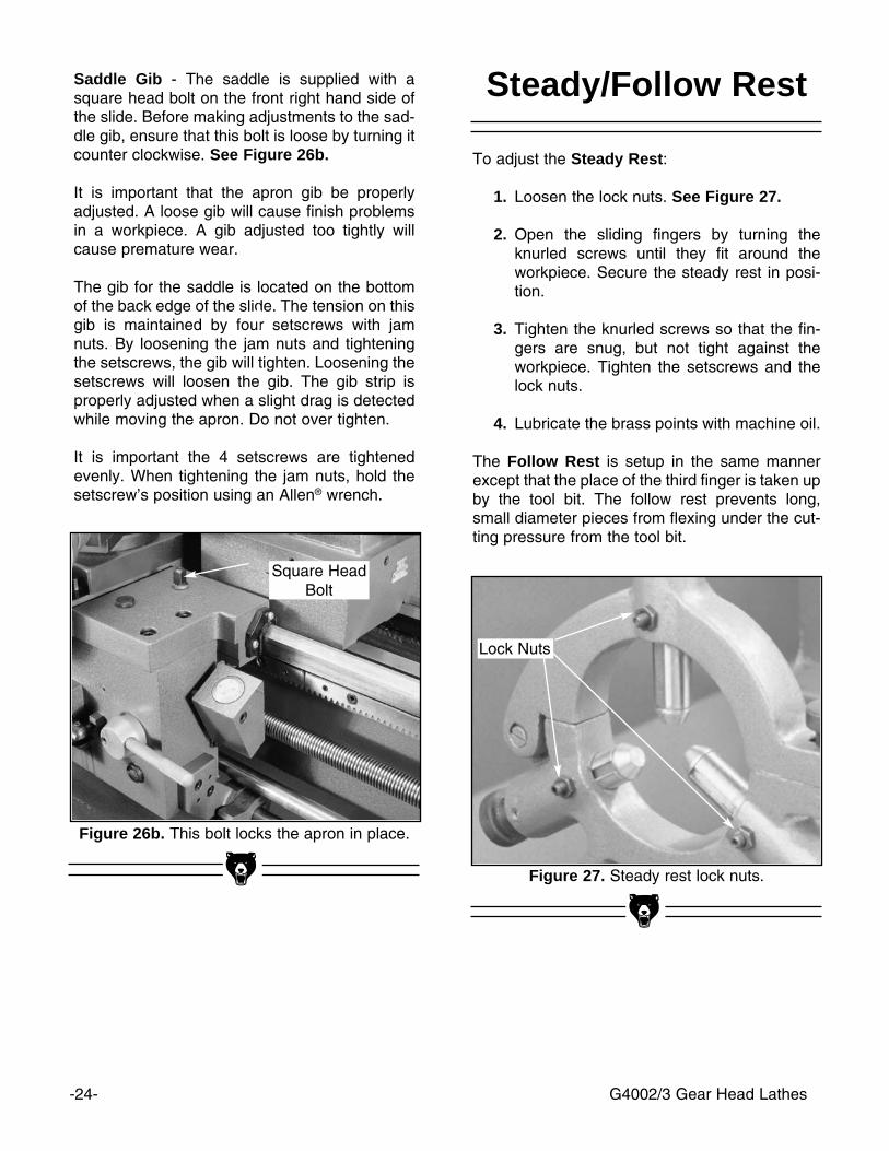
Figure 25.Adjusting the cross-slide gib.
There are three main gib adjustments for theModel G4002/3. They are: the cross-slide gib, thecompound slide gib and the saddle gib.
Cross-slide Gib - The gib on the cross-slide isadjusted by the two screws located at each end.See Figure 25. To adjust, loosen the setscrewlocated along the edge of the cross-slide. This setscrew is provided for locking the slide forcertain operations. After making the adjustmentsdetailed below, tighten the setscrew until it justtouches the gib.
The gib is wedge shaped and by loosening thescrew closest to the operator and then tighteningthe opposite screw, the slide will become looser.Conversely, loosening the screw furthest awayfrom the operator and tightening the closer screwwill tighten the gib. Do not over tighten. Adjust thegib so that it creates a slight drag when the slideis in motion. Test the ease of motion with the gibslightly loose. Begin tightening the gib and testafter making small adjustments. When a slightdrag is detected the gib is properly adjusted.
Gibs
-24- G4002/3 Gear Head Lathes
Saddle Gib - The saddle is supplied with asquare head bolt on the front right hand side ofthe slide. Before making adjustments to the sad-dle gib, ensure that this bolt is loose by turning itcounter clockwise. See Figure 26b.
It is important that the apron gib be properlyadjusted. A loose gib will cause finish problemsin a workpiece. A gib adjusted too tightly willcause premature wear.
The gib for the saddle is located on the bottomof the back edge of the slide. The tension on thisgib is maintained by four setscrews with jamnuts. By loosening the jam nuts and tighteningthe setscrews, the gib will tighten. Loosening thesetscrews will loosen the gib. The gib strip isproperly adjusted when a slight drag is detectedwhile moving the apron. Do not over tighten.
It is important the 4 setscrews are tightenedevenly. When tightening the jam nuts, hold thesetscrew’s position using an Allen® wrench.
Figure 27. Steady rest lock nuts.
Figure 26b. This bolt locks the apron in place.
Steady/Follow Rest
To adjust the Steady Rest:
1. Loosen the lock nuts. See Figure 27.
2. Open the sliding fingers by turning theknurled screws until they fit around theworkpiece. Secure the steady rest in posi-tion.
3. Tighten the knurled screws so that the fin-gers are snug, but not tight against theworkpiece. Tighten the setscrews and thelock nuts.
4. Lubricate the brass points with machine oil.
The Follow Rest is setup in the same mannerexcept that the place of the third finger is taken upby the tool bit. The follow rest prevents long,small diameter pieces from flexing under the cut-ting pressure from the tool bit.
Lock Nuts
Square HeadBolt
G4002/3 Gear Head Lathes -25-
Figure 28. Finished dead center.
Tailstock
The tailstock on the Model G4002/3 is aligned atthe factory with the headstock. It is recommend-ed that you take the time to ensure that the tail-stock is aligned to your own desired tolerances.To align the tailstock:
1. Center drill a 6'' long piece of bar stock onboth ends. Set it aside for use in step 4.
2. Make a dead center by turning a shoulderto make a shank. Flip the piece over in thechuck and turn a 60° point. See Figure 28.As long as it remains in the chuck, the pointof your center will be accurate to your spin-dle’s axis. Keep in mind that the point willhave to be refinished whenever it isremoved and returned to the chuck.
Figure 29. Bar stock mounted on centers.
Figure 30. Adjusting for headstock end taper.3. Place the live center in your tailstock.
4. Attach a lathe dog to the bar stock andmount it between the centers. See Figure29.
5. Turn approximately .010" off the diameter.
6. Measure the stock with a micrometer. If thestock is fat at the tailstock end, the tailstockneeds to be moved toward you the amountof the taper. See Figure 30.
TIPBefore making adjustments to the tailstock,mount a dial indicator so that the dial’s plungeris on the tailstock barrel. See Figure 30.
Viewed from above.
-26- G4002/3 Gear Head Lathes
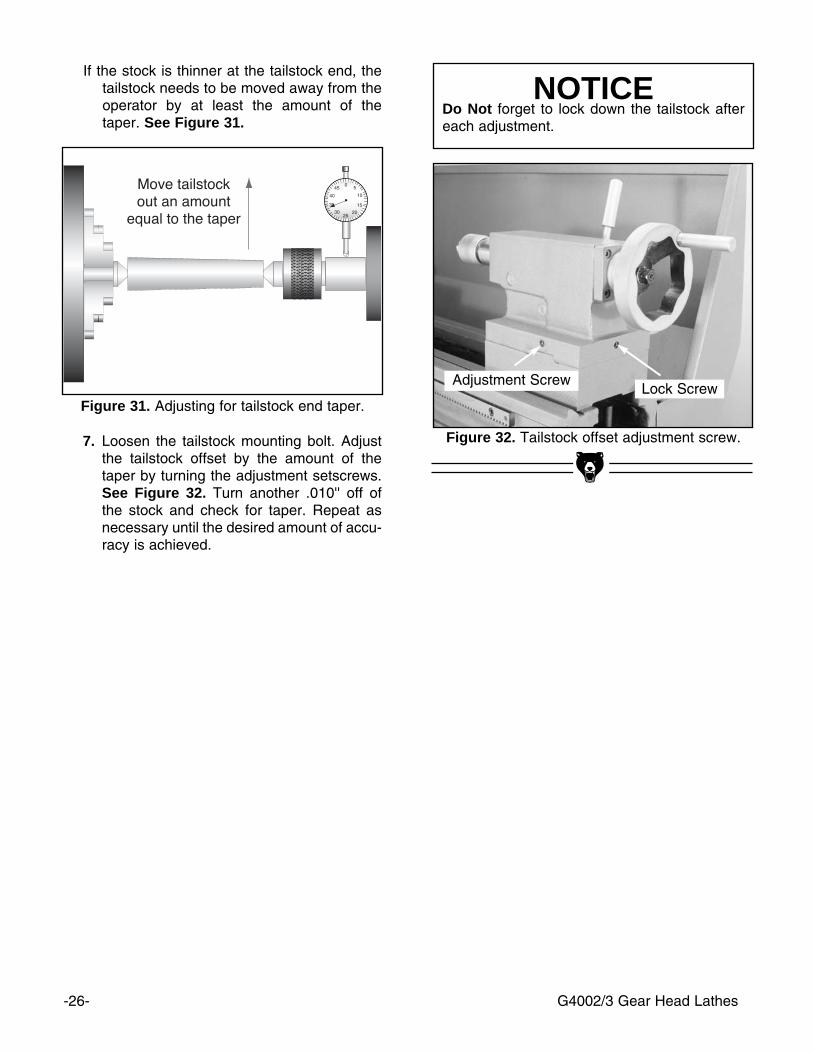
NOTICEDo Not forget to lock down the tailstock aftereach adjustment.
Figure 31. Adjusting for tailstock end taper.
Figure 32. Tailstock offset adjustment screw.7. Loosen the tailstock mounting bolt. Adjustthe tailstock offset by the amount of thetaper by turning the adjustment setscrews.See Figure 32. Turn another .010'' off ofthe stock and check for taper. Repeat asnecessary until the desired amount of accu-racy is achieved.
Adjustment ScrewLock Screw
If the stock is thinner at the tailstock end, thetailstock needs to be moved away from theoperator by at least the amount of thetaper. See Figure 31.
G4002/3 Gear Head Lathes -27-
SECTION 7: MAINTENANCE
Lubrication
Quick Change Gearbox - Lubrication for theGearbox is provided through 3 oil points, labeledoil nipple. Add a squirt or two of oil after everythree-to-four hours of use. See Figure 35.
Motor - The bearings used in the motor areshielded and lubricated for life.
Your Model G4002/3 will function best when it isclean and well lubricated. Take the time to wipedown and oil the machine after use. We recom-mend using ISO 68 or SAE 20W non-detergentoil unless otherwise specified.
Apron - Apply lubrication to the apron throughthe 2 ball fittings on the top face of the apron andone near the apron handwheel. See Figure 33.There is a level glass on the front of the apronand a fill plug on top. Make sure the oil level isbetween the 2 red marks on the glass beforeusing lathe.
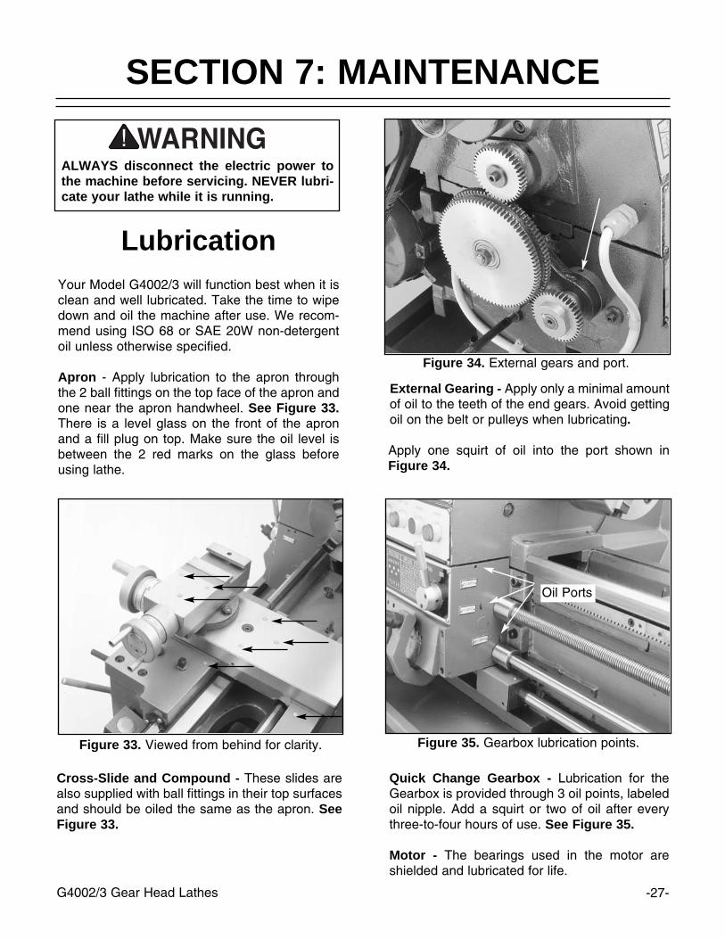
External Gearing - Apply only a minimal amountof oil to the teeth of the end gears. Avoid gettingoil on the belt or pulleys when lubricating.
Apply one squirt of oil into the port shown inFigure 34.
Figure 33. Viewed from behind for clarity. Figure 35. Gearbox lubrication points.
Figure 34. External gears and port.
ALWAYS disconnect the electric power tothe machine before servicing. NEVER lubri-cate your lathe while it is running.
Cross-Slide and Compound - These slides arealso supplied with ball fittings in their top surfacesand should be oiled the same as the apron. SeeFigure 33.
Oil Ports
Bearing Preload
This lathe is shipped from the factory with thebearing preload already set. If the preloadrequires resetting for whatever reason, pleasecontact our service department for furtherinstructions.
Slides and Ways - Apply oil to the ways andslides after each use. Wipe the ways with a cleanrag prior to lubrication to ensure that no grime iscarried along with your lubricant into friction-sen-sitive areas. Applying oil to the bedways andother bare metal parts also protect the lathe fromrust and pitting.
Lead Screw and Feed Rod - Be sure to cleanand lubricate the leadscrew, feed rod and switchcontrol rod. The lead screw and feed rod have abearing on the tail stock end support that willrequire one to two squirts of oil. See Figure 36.
Headstock Gearbox - The oil in the headstockshould be changed after the first 2 hours of use.Then, every 6 months, depending on usage. It isrecommended that a light weight, non detergentoil be used. Viscosity can range from 10W to30W and may include multi-viscosity oil in thissame range.
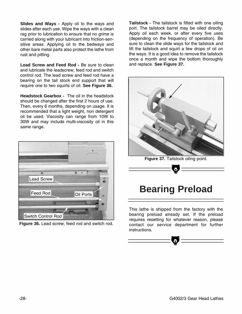
Tailstock - The tailstock is fitted with one oilingport. The tailstock barrel may be oiled directly.Apply oil each week, or after every five uses(depending on the frequency of operation). Besure to clean the slide ways for the tailstock andlift the tailstock and squirt a few drops of oil onthe ways. It is a good idea to remove the tailstockonce a month and wipe the bottom thoroughlyand replace. See Figure 37.
Figure 36. Lead screw, feed rod and switch rod.
Figure 37. Tailstock oiling point.
Switch Control Rod
Feed Rod Oil Ports
Lead Screw
-28- G4002/3 Gear Head Lathes

-29-G4002/3 Gear Head Lathes
NOTICEThe Model G4002/3 was specifically designedfor turning operations. DO NOT MODIFYAND/OR USE THIS LATHE FOR ANYOTHER PURPOSE. Modifications orimproper use of this tool will void the war-ranty. If you are confused about any aspect ofthis machine, DO NOT use it until you haveanswered all your questions.
The following pages contain general machinedata, parts diagram, parts lists and Warranty/Returninformation for your Model G4002/3.
If you need parts or help in assembling yourmachine, or if you need operational information,we encourage you to call our ServiceDepartment. Our trained service technicians willbe glad to help you. If you have comments deal-ing specifically with this manual, please write toour Bellingham, Washington location using theaddress in the Introduction section of this manu-al.
The specifications, drawings, and photographsillustrated in this manual represent the ModelG4002/3 as supplied when the manual was pre-pared. However, due to Grizzly’s policy of contin-uous improvement, changes may be made at anytime with no obligation on the part of Grizzly.Whenever possible, though, we send manualupdates to all owners of a particular tool ormachine. Should you receive one, add the newinformation to this manual and keep it for refer-ence.
We have included some important safety mea-sures that are essential to this machine’s opera-tion. While most safety measures are generallyuniversal, Grizzly reminds you that each workshop is different and safety rules should be con-sidered as they apply to your specific situation.
We recommend you keep a copy of our currentcatalog for complete information regardingGrizzly's warranty and return policy. If you needadditional technical information relating to thismachine, or if you need general assistance orreplacement parts, please contact the ServiceDepartment listed in the General Information.
This machine is designed for highly-skilled indi-viduals who have an understanding of metal-working. We realize there are numerous kinds ofcutters and specialized techniques used to turnmetals. To list all of the techniques necessary tooperate a metal lathe correctly for specific appli-cations would require many volumes. Additionalinformation sources are necessary to realize thefull potential of this machine. Trade journals, met-alworking magazines, and your local library aregood places to start.
SECTION 8: CLOSURE
As with all power tools, there is dangerassociated with the Model G4002/3. Use thetool with respect and caution to lessen thepossibility of mechanical damage or opera-tor injury. If normal safety precautions areoverlooked or ignored, injury to the opera-tor or others in the area is likely.

-30- G4002/3 Gear Head Lathes
Design Type ......................................................................................................Floor Model
Overall Dimensions:Overall Length ..........................................................................................................53"Overall Width ............................................................................................................26"Height With Optional Stand ..................................................................................521⁄2"Height Without Optional Stand ................................................................................23"Bed Width ................................................................................................................71⁄4"Spindle Bore ..........................................................................................................17⁄16''Spindle Taper ......................................................................................#5 Morse TaperTailstock Taper ....................................................................................#3 Morse TaperTailstock Barrel Diameter ......................................................................................19⁄16''Weight (Net) ......................................................................................................913 lbs. Weight (Shipping)............................................................................................1015 lbs.Crate Size ..................................................................................59" L x 30" W x 29" HFootprint ........................................................................................................53" x 23"
Construction: ........................................................................................................Cast IronCapacity:
Swing Over Bed ......................................................................................................12''Swing Over Gap ......................................................................................................17''Swing Over Cross Slide ............................................................................................7''Distance Between Centers ......................................................................................24''Spindle..................................................................................................D1-4 Cam LockCompound Travel ....................................................................................................31⁄4''Cross Slide Travel ..................................................................................................61⁄4''Tailstock Barrel Travel................................................................................................4''Spindle Speeds............................70, 200, 220, 270, 360, 600, 800, 1000, 1400 RPMFeed Rate Range ..........................................................................40 @ .0011'' - .031''Thread Range Inch ....................................................................40 @ 4 TPI - 112 TPIThread Range Metric ........................................................................29 @ .2 - 4.5 mm
Motor:Type ............................................................................TEFC Capacitor Start InductionHorsepower ..............................................................................................................11⁄2Phase ⁄ Hertz ................................................................................Single Phase ⁄ 60HzVoltage ..................................................................................................................220VAmps............................................................................................................................9RPM ......................................................................................................................1725Bearings ....................................................................Shielded And Lubricated For Life
Features:........................................................................6'' 3-Jaw Chuck With Two Set Of Jaws..........................................................................8'' 4-Jaw Chuck With Reversible Jaws............................................................Quick Change Tool Post With One Tool Holder..........................................................................................................Extra Tool Holder..................................................................................................................Steady Rest
....................................................................................................................Follow Rest..............................................................................................................10'' Face Plate....................................................................1⁄2'' Drill Chuck W⁄ # 3 Morse Taper Arbor..................................................2- #3 Morse Taper Dead Centers (1 Carbide Tipped)..........................................................................................#3 Morse Taper Live Center..................................................................................................Set of 6 Change Gears........................................................................................................................Tool Box
Specifications, while deemed accurate, are not guaranteed.
Customer Service #: (570) 326-3806 • To Order Call: (800) 523-4777 • Fax #: (800) 438-5901
GRIZZLY MODEL G4002 12" X 24" GEAR HEAD LATHE
MACHINE DATASHEET

Design Type ......................................................................................................Floor Model
Overall Dimensions:Overall Length ..........................................................................................................61"Overall Width ............................................................................................................23"Height With Optional Stand ..................................................................................541⁄2"Height W⁄O Optional Stand ......................................................................................23"Bed Width ................................................................................................................71⁄4"Spindle Bore ..........................................................................................................17⁄16''Spindle Taper ......................................................................................#5 Morse TaperTailstock Taper ....................................................................................#3 Morse TaperWeight (Net) ......................................................................................................917 lbs. Weight (Shipping)............................................................................................1040 lbs.Crate Size ..................................................................................66" L x 30" W x 28" HFootprint ........................................................................................................61" x 23"
Construction: ........................................................................................................Cast IronCapacity:
Swing Over Bed ......................................................................................................12''Swing Over Gap ......................................................................................................17''Swing Over Cross Slide ............................................................................................7''Distance Between Centers ......................................................................................36''Spindle..................................................................................................D1-4 Cam LockCompound Travel ....................................................................................................31⁄4''Cross Slide Travel ..................................................................................................61⁄4''Tailstock Barrel Travel................................................................................................4''Spindle Speeds............................70, 200, 220, 270, 360, 600, 800, 1000, 1400 RPMFeed Rate Range ..........................................................................40 @ .0011'' - .031''Thread Range Inch ....................................................................40 @ 4 TPI - 112 TPIThread Range Metric ........................................................................29 @ .2 - 4.5 mm
Motor:Type ............................................................................TEFC Capacitor Start InductionHorsepower ..............................................................................................................11⁄2Phase ⁄ Hertz ................................................................................Single Phase ⁄ 60HzVoltage ..................................................................................................................220VAmps............................................................................................................................9RPM ......................................................................................................................1725Bearings ....................................................................Shielded And Lubricated For Life
Features:......................................................................6'' 3-Jaw Chuck With Two Sets Of Jaws..........................................................................8'' 4-Jaw Chuck With Reversible Jaws............................................................Quick Change Tool Post With One Tool Holder..........................................................................................................Extra Tool Holder..................................................................................................................Steady Rest
....................................................................................................................Follow Rest..............................................................................................................10'' Face Plate
......................................................................1/2'' Drill Chuck W/ #3 Morse Taper Arbor................................................2- #3 Morse Taper Dead Centers (1 Carbide Tipped)........................................................................................ #3 Morse Taper Live Center..........................................................................................................................Oil Can..............................................................................................Set Of Six Change Gears........................................................................................................................Tool Box
Specifications, while deemed accurate, are not guaranteed.
G4002/3 Gear Head Lathes -31-
Customer Service #: (570) 326-3806 • To Order Call: (800) 523-4777 • Fax #: (800) 438-5901
GRIZZLY MODEL G4003 12" X 36" GEAR HEAD LATHE
MACHINE DATASHEET
-32- G4002/3 Gear Head Lathes
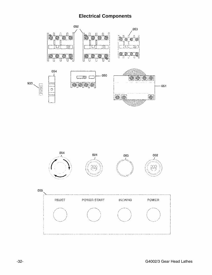
Electrical Components

-33-G4002/3 Gear Head Lathes
REF PART # DESCRIPTION001 P4002001 START BUTTON002 P4002002 INDICATOR LIGHT003 P4002003 JOG BUTTON004 P4002004 RESET BUTTON050 P4002050 THERMAL PROT. BLOCK051 P4002051 TRANSFORMER052 P4002052 MAGNETIC CONTACTOR053 P4002053 MAGNETIC CONTACTOR054 P4002054 FUSE HOLDER055 P4002055 CONTROL PANEL PLATE933 P4002933 FUSE 2 AMP
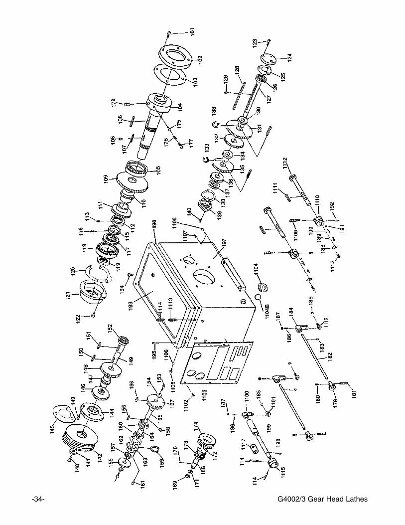
-34- G4002/3 Gear Head Lathes

-35-G4002/3 Gear Head Lathes
REF PART # DESCRIPTION
101 P4002101 SCREW102 P4002102 COVER103 P4002103 OIL SEAL104 P4002104 SPINDLE105 P7212 BEARING D-7212106 P4002106 KEY107 P4002107 KEY108 P4002108 SCREW109 P4002109 GEAR110 P4002110 GEAR111 P4002111 GEAR112 P4002112 NUT113 P4002113 SCREW114 P4002114 PIN115 P4002115 COLLAR116 P4002116 SCREW117 P4002117 GEAR118 P7211 BEARING D-7211119 P4002119 NUT120 P4002120 OIL SEAL121 P4002121 COVER122 P4002122 SCREW123 P4002123 SCREW124 P4002124 COVER125 P4002125 OIL SEAL126 P60304 BEARING 60304127 P4002127 SHAFT128 P4002128 KEY129 P4002129 SCREW130 P4002130 GEAR131 P4002131 GEAR132 P4002132 GEAR133 P4002133 C-CUP134 P4002134 GEAR135 P4002135 GEAR136 P4002136 GEAR137 P6004 BALL BEARING 6004138 P4002138 OIL SEAL139 P4002139 COVER
REF PART # DESCRIPTION
140 P4002140 SCREW141 P4002141 WASHER142 P4002142 PULLEY143 P4002143 SCREW144 P4002144 COVER145 P4002145 OIL SEAL146 P4002146 GEAR147 P4002147 GEAR148 P4002148 GEAR149 P4002149 SHAFT150 P4002150 KEY151 P4002151 KEY152 P6004 BALL BEARING 6004153 P4002153 SCREW154 P4002154 WASHER155 P4002155 GEAR156 P4002156 KEY157 P4002157 OIL SEAL 20 X 45 X 10158 P4002158 C-CLIP159 P4002159 C-CLIP160 P6004 BALL BEARING 6004161 P4002161 SCREW162 P4002162 OIL SEAL163 P4002163 COVER164 P4002164 COLLAR165 P4002165 SHAFT166 P4002166 KEY167 P4002167 GEAR168 P4002168 SHAFT169 P4002169 OIL SEAL170 P4002170 SCREW171 P4002171 C-CLIP172 P4002172 C-CLIP173 P6204 BALL BEARING 6204174 P4002174 GEAR175 P4002175 LOCK PIN176 P4002176 SPRING177 P4002177 SCREW

-36- G4002/3 Gear Head Lathes
REF PART # DESCRIPTIONz178 P4002178 ECCENTRIC SHAFT179 P4002179 GEAR180 P4002180 SCREW 181 P4002181 PIN182 P4002182 SHAFT 183 P4002183 OIL SEAL184 P4002184 SHAFT ARM 185 P4002185 C-CLIP186 P4002186 SCREW 187 P4002187 NUT 188 P4002188 SIGN BOARD189 P4002189 SCREW 190 P4002190 SPRING191 P4002191 BALL192 P4002192 SCREW 193 P4002193 COVER 194 P4002194 SCREW 195 P4002195 SCREW 196 P4002196 OIL SEAL197 P4002197 HEAD STOCK198 P4002198 SHAFT 199 P4002199 COLLAR1100 P40021100 SHIFTER ARM1101 P40021101 SHIFTER1102 P1183108 RIVET 1103 P40021103 SIGN BOARD1104 P40021104 OIL WINDOW1104B P40021104B O-RING1105 P40021105 SCREW 1106 P40021106 OIL SEAL1107 P40021107 SCREW 1108 P40021108 SCREW1109 P40021109 HANDLE1110 P40021110 BOSS1111 P40021111 KEY 1112 P40021112 GEAR1113 P40021113 SCREW 1114 P40021114 SCREW 1115 P40021115 BOSS1116 P40021116 SHIFTER 1117 P40021117 COLLAR
-37-G4002/3 Gear Head Lathes
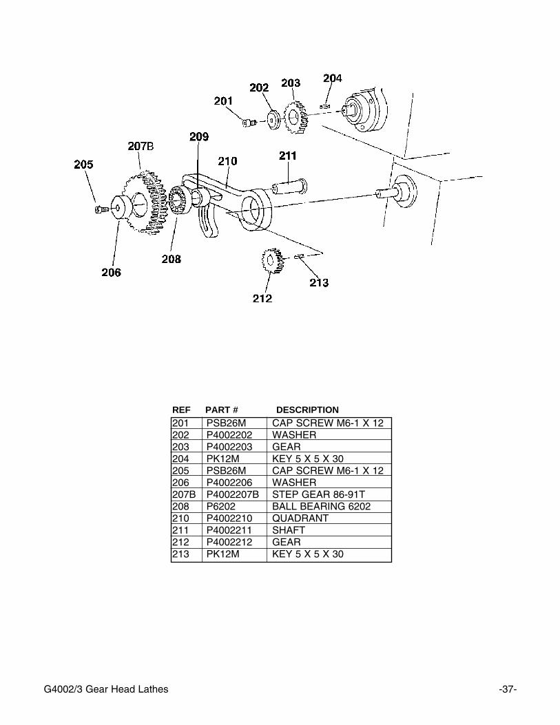
REF PART # DESCRIPTION201 PSB26M CAP SCREW M6-1 X 12202 P4002202 WASHER203 P4002203 GEAR204 PK12M KEY 5 X 5 X 30205 PSB26M CAP SCREW M6-1 X 12206 P4002206 WASHER207B P4002207B STEP GEAR 86-91T208 P6202 BALL BEARING 6202210 P4002210 QUADRANT211 P4002211 SHAFT212 P4002212 GEAR213 PK12M KEY 5 X 5 X 30
-38- G4002/3 Gear Head Lathes

-39-G4002/3 Gear Head Lathes
REF PART # DESCRIPTION
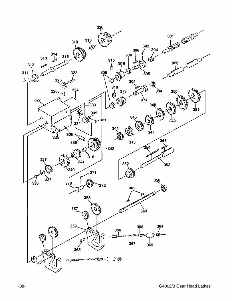
301 P4002301 LEAD SCREW302 P4002302 PIN304 P8103 BEARING 8103305 P4002305 SHAFT306 PK19M KEY 5 X 5 X 14308 P4002308 GEAR309 PN09M HEX NUT M12-1.75310 P4002310 WASHER311 P4002311 SCREW312 P4002312 COVER313 PK12M KEY 5 X 5 X 30314 PK06M KEY 5 X 5 X 10315 P4002315 SHAFT316 P4002316 BUSHING318 P4002318 GEAR320 P4002320 GEAR322 P4002322 LEVER323 P4002323 FEED ROD323A P4002323A LEAD SCREW324 P4002324 SCREW325 P4002325 BOSS326 P4002326 PIN327 P4002327 GEAR BOX327A P4002327A COMPLETE GEAR BOX328 P4002328 PLATE329 P4002329 SCREW330 P4002330 SHAFT331 PEC04M E-CLIP 13MM332 P4002332 SHIFT PIVOT333 P4002333 PIN334 P4002334 SHIFT YOKE335 PSB26M CAP SCREW M6-1 X 12336 P4002336 WASHER337 P4002337 GEAR338 P4002338 HALF NUTS339 P4002339 WORM340 P4002340 GEAR341 P4002341 GEAR
REF PART # DESCRIPTION
342 P4002342 GEAR343 P4002343 GEAR344 P4002344 GEAR345 P4002345 GEAR346 P4002346 GEAR347 P4002347 GEAR348 P4002348 GEAR349 P4002349 GEAR350 P4002350 GEAR351 P4002351 GEAR352 P4002352 GEAR353 P4002353 SHAFT354 P4002354 KEY 5 x 5 x 75355 PK02M KEY 5 X 5 X 40356 P4002356 BEARING 7000102357 P4002357 GEAR358 P4002358 GEAR359 P4002359 SHIFT LEVER362 P4002362 KEY363 P4002363 SHAFT364 PN01M HEX NUT M6-1.0365 P4002365 SHAFT366 P4002366 SHAFT367 P4002367 SPRING368 P4002368 SLEEVE369 P4002369 HOUSING370 P4002370 SHAFT371 P4002371 SCREW372 P4002372 GEAR373 P4002373 GEAR374 P4002374 SHAFT
-40- G4002/3 Gear Head Lathes

-41-G4002/3 Gear Head Lathes
REF PART # DESCRIPTION
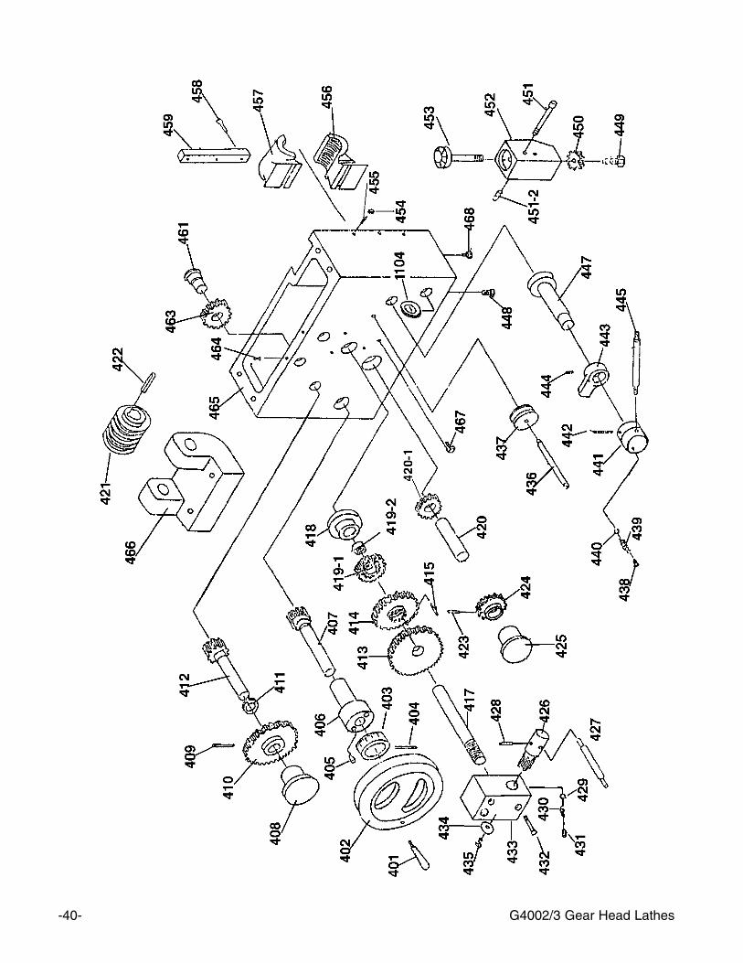
401 P4002401 HANDLE402 P4002402 HAND WHEEL403 P4002403 INDEXING RING404 P4002404 PIN405 P4002405 SCREW406 P4002406 BRACKET407 P4002407 GEAR SHAFT408 P4002408 BUSHING409 PRP05M ROLL PIN 5 X 30410 P4002410 GEAR411 P4002411 RETAINING RING412 P4002412 GEAR SHAFT413 P4002413 GEAR414 P4002414 GEAR415 P4002415 PIN417 P4002417 SHAFT418 P4002418 BUSHING419-1 P4002419-1 GEAR419-2 P4002419-2 SPACER420 P4002420 SHAFT421 P4002421 WORM422 P4002422 FLAT KEY423 PRP06M ROLL PIN 5 X 24424 P4002424 GEAR425 P4002425 BUSHING426 P4002426 GEAR SHAFT427 P4002427 LEVER428 P4002428 PIN429 P4002429 BALL430 P4002430 SPRING431 P4002431 SCREW432 P4002432 SCREW433 P4002433 BOSS434 P4002434 WASHER435 P4002435 SCREW
REF PART # DESCRIPTION
436 P4002436 SHAFT437 P4002437 SAFETY SHIFTER438 P4002438 SCREW439 P4002439 SPRING440 P4002440 BALL441 P4002441 BOSS442 P4002442 PIN443 P4002443 DOG444 P4002444 SCREW445 P4002445 LEVER447 P4002447 SHAFT448 P4002448 SCREW449 PSB28M CAP SCREW M6-1 X 15450 P4002450 GEAR451 P4002451 SCREW451-2 P4002451-2 SPACER452 P4002452 HOUSING453 P4002453 THREAD DIAL454 PN01M HEX NUT M6-1.0455 P4002455 SCREW456 P4002456 HALF NUT457 P4002457 HALF NUT HOUSING458 P4002458 SCREW459 P4002459 GIB461 P4002461 SHAFT463 P4002463 GEAR464 P4002464 SCREW465 P4002465 APRON CASE466 P4002466 WORM BRACKET467 P4002467 LIMIT BLOCK468 P4002468 SCREW
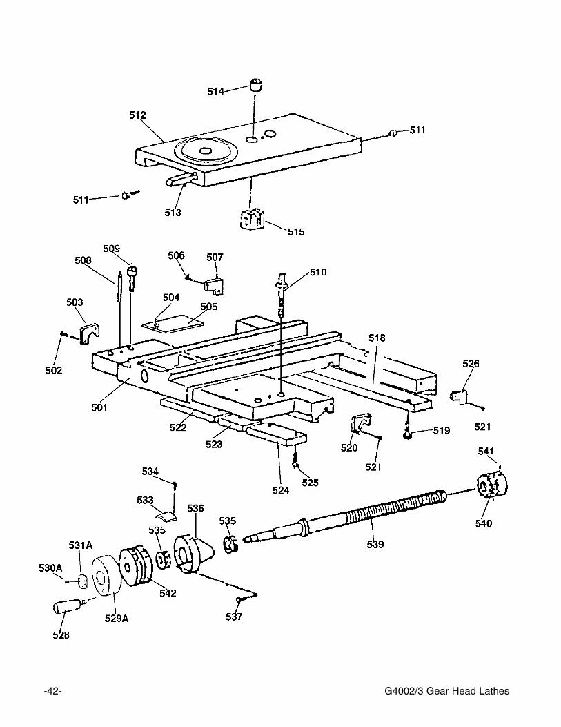
-42- G4002/3 Gear Head Lathes

G4002/3 Gear Head Lathes -43-
REF PART # DESCRIPTION
501 P4002501 SADDLE502 P4002502 SCREW503 P4002503 WIPER504 P4002504 SCREW505 P4002505 COVER506 P4002506 SCREW507 P4002507 WIPER508 P4002508 PIN509 P4002509 SCREW510 P4002510 SCREW511 P4002511 SCREW512 P4002512 CROSS SLIDE513 P4002513 GIB514 P4002514 BUSHING515 P4002515 NUT518 P4002518 SLIDE PLATE519 P4002519 SCREW520 P4002520 WIPER521 P4002521 SCREW522 P4002522 SLIDE PLATE523 P4002523 SLIDE PLATE524 P4002524 SLIDE PLATE525 PB19M HEX BOLT M8-1.25 X 24526 P4002526 WIPER527 P4002527 SCREW528 P4002528 HANDLE529A P4002529A BRACKET530A P4002530A SET SCREW531A P4002531A SPANNER NUT533 P4002533 SIGN BOARD534 P4002534 SCREW535 P8102 BEARING 8102536 P4002536 BRACKET537 PSB06M CAP SCREW M6-1 X 25539 P4002539 LEAD SCREW540 P4002540 GEAR541 P4002541 SCREW542 P4002542 DIAL543 P4002543 SCREW
-44- G4002/3 Gear Head Lathes
REF PART # DESCRIPTION
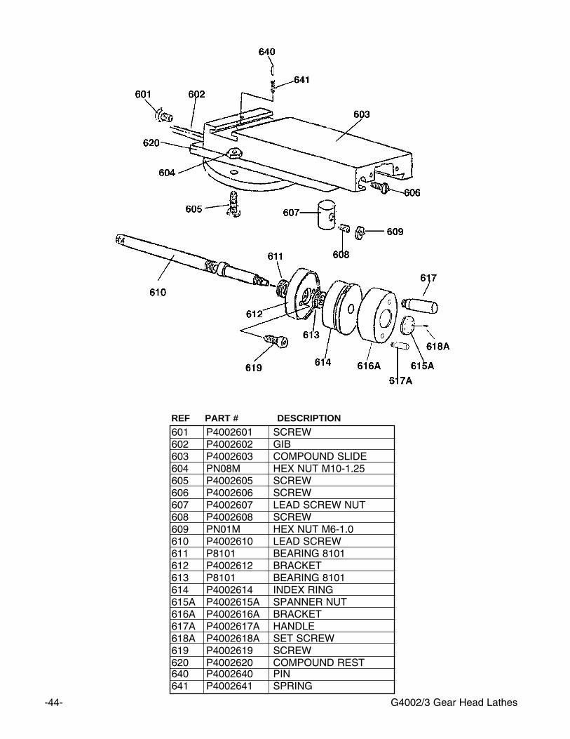
601 P4002601 SCREW602 P4002602 GIB603 P4002603 COMPOUND SLIDE604 PN08M HEX NUT M10-1.25605 P4002605 SCREW606 P4002606 SCREW607 P4002607 LEAD SCREW NUT608 P4002608 SCREW609 PN01M HEX NUT M6-1.0610 P4002610 LEAD SCREW611 P8101 BEARING 8101612 P4002612 BRACKET613 P8101 BEARING 8101614 P4002614 INDEX RING615A P4002615A SPANNER NUT616A P4002616A BRACKET617A P4002617A HANDLE618A P4002618A SET SCREW619 P4002619 SCREW620 P4002620 COMPOUND REST640 P4002640 PIN641 P4002641 SPRING
-45-G4002/3 Gear Head Lathes

-46- G4002/3 Gear Head Lathes
REF PART # DESCRIPTION
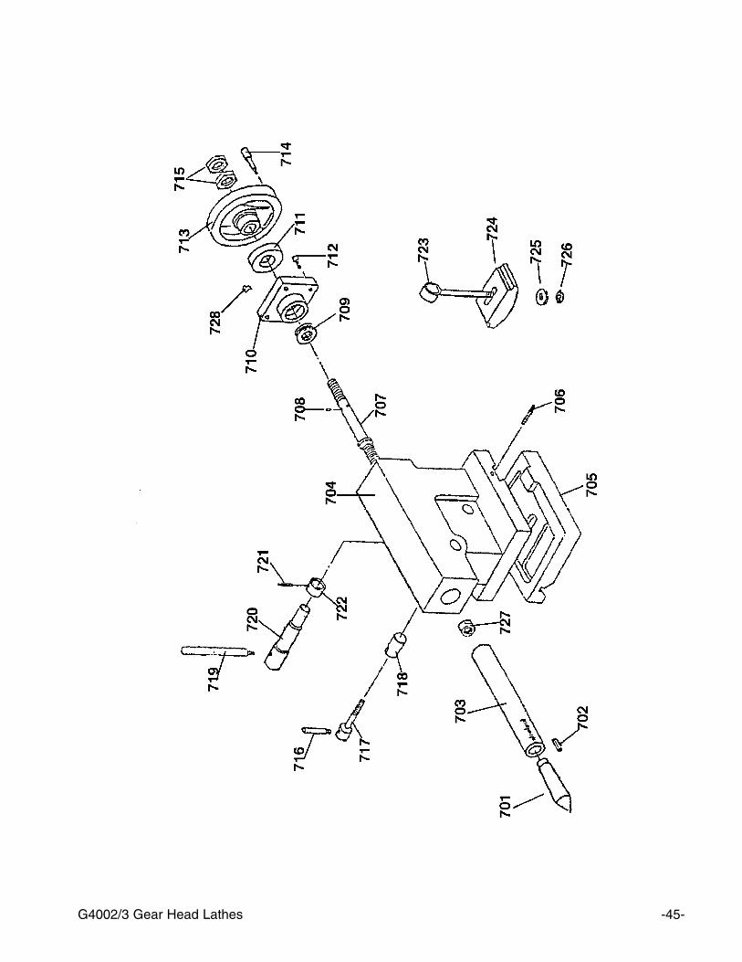
701 P4002701 CENTER702 P4002702 KEY703 P4002703 QUILL704 P4002704 TAIL STOCK705 P4002705 BASE706 P4002706 SCREW707 P4002707 SCREW708 P4002708 PIN709 P8101 BEARING 8101710 P4002710 BRACKET711 P4002711 INDEX RING712 P4002712 SCREW713 P4002713 HAND WHEEL714 P4002714 HANDLE715 PN09M HEX NUT M12-1.75716 P4002716 HANDLE717 P4002717 LOCK SCREW718 P4002718 LOCK SHAFT719 P4002719 HANDLE720 P4002720 SHAFT721 P4002721 PIN722 P4002722 COLLAR723 P4002723 SHAFT724 P4002724 BASE SHOE BLOCK725 PW06M FLAT WASHER 12MM726 PN09M HEX NUT M12-1.75727 P4002727 NUT728 P4002728 INDEX730 P4002730 HANDLE STOP
G4002/3 Gear Head Lathes -47-
REF PART # DESCRIPTION
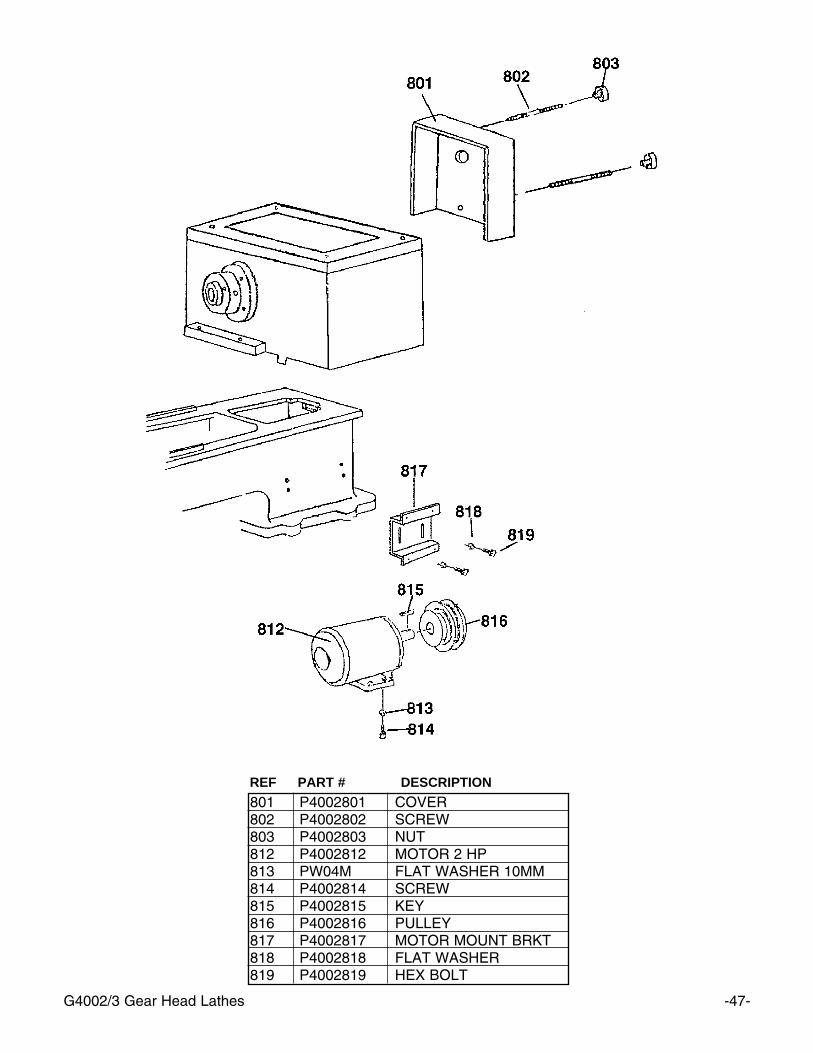
801 P4002801 COVER802 P4002802 SCREW803 P4002803 NUT812 P4002812 MOTOR 2 HP813 PW04M FLAT WASHER 10MM814 P4002814 SCREW815 P4002815 KEY816 P4002816 PULLEY817 P4002817 MOTOR MOUNT BRKT818 P4002818 FLAT WASHER819 P4002819 HEX BOLT
-48- G4002/3 Gear Head Lathes
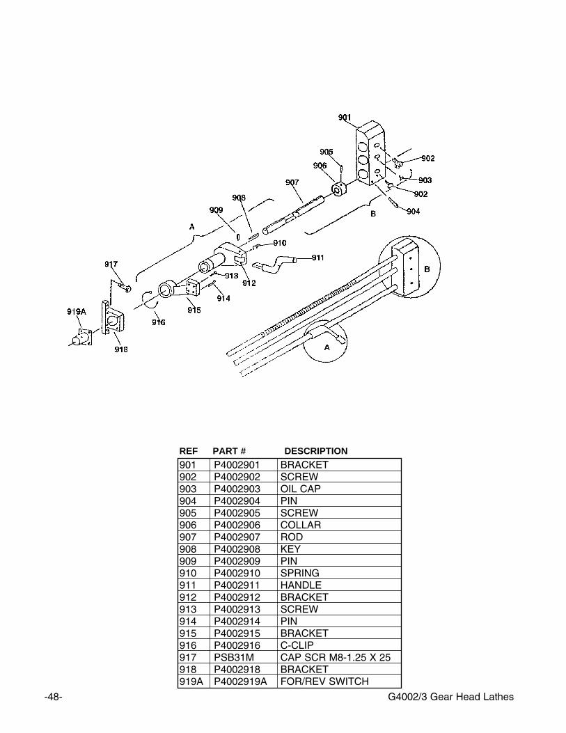
REF PART # DESCRIPTION
901 P4002901 BRACKET 902 P4002902 SCREW903 P4002903 OIL CAP904 P4002904 PIN905 P4002905 SCREW906 P4002906 COLLAR907 P4002907 ROD908 P4002908 KEY909 P4002909 PIN910 P4002910 SPRING911 P4002911 HANDLE912 P4002912 BRACKET913 P4002913 SCREW914 P4002914 PIN915 P4002915 BRACKET916 P4002916 C-CLIP917 PSB31M CAP SCR M8-1.25 X 25918 P4002918 BRACKET919A P4002919A FOR/REV SWITCH
G4002/3 Gear Head Lathes -49-
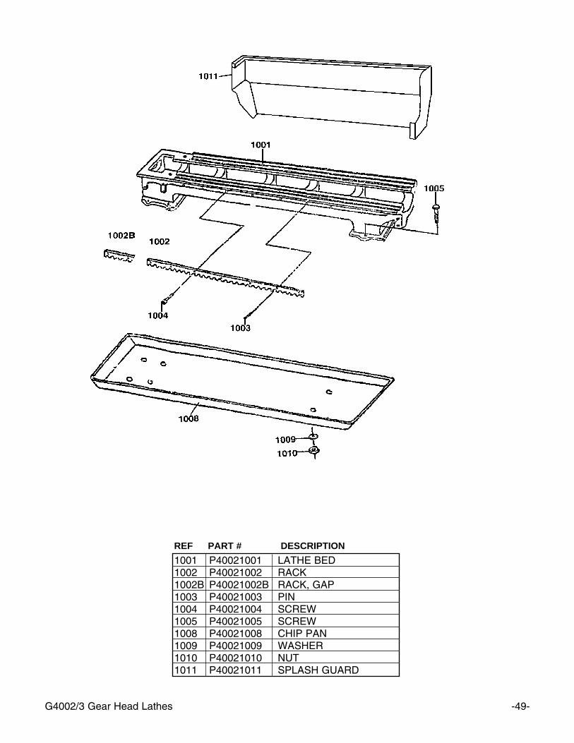
REF PART # DESCRIPTION
1001 P40021001 LATHE BED1002 P40021002 RACK1002B P40021002B RACK, GAP1003 P40021003 PIN1004 P40021004 SCREW1005 P40021005 SCREW1008 P40021008 CHIP PAN1009 P40021009 WASHER1010 P40021010 NUT1011 P40021011 SPLASH GUARD

-50- G4002/3 Gear Head Lathes
Grizzly Imports, Inc. warrants every product it sells for a period of 1 year to the original purchaser from thedate of purchase. This warranty does not apply to defects due directly or indirectly to misuse, abuse, neg-ligence, accidents, repairs or alterations or lack of maintenance. This is Grizzly’s sole written warranty andany and all warranties that may be implied by law, including any merchantability or fitness, for any particu-lar purpose, are hereby limited to the duration of this written warranty. We do not warrant or represent thatthe merchandise complies with the provisions of any law or acts unless the manufacturer so warrants. Inno event shall Grizzly’s liability under this warranty exceed the purchase price paid for the product and anylegal actions brought against Grizzly shall be tried in the State of Washington, County of Whatcom.
We shall in no event be liable for death, injuries to persons or property or for incidental, contingent, spe-cial, or consequential damages arising from the use of our products.
To take advantage of this warranty, contact us by mail or phone and give us all the details. We will thenissue you a “Return Number’’, which must be clearly posted on the outside as well as the inside of the car-ton. We will not accept any item back without this number. Proof of purchase must accompany the mer-chandise.
The manufacturers reserve the right to change specifications at any time because they constantly strive toachieve better quality equipment. We make every effort to ensure that our products meet high quality anddurability standards and we hope you never need to use this warranty.
Please feel free to write or call us if you have any questions about the machine or the manual.
Thank you again for your business and continued support. We hope to serve you again soon.
WARRANTY AND RETURNS

WARRANTY CARDNAME_______________________________________________ PHONE NUMBER___________________STREET________________________________________________________________________________CITY_______________________________STATE_________ZIP ___________________________________MODEL# _________________ INVOICE#_________________
The following information is given on a voluntary basis. This information will be used for marketing purposes to helpGrizzly develop better products. Your name will be included in our mailing list only. It will not be sold to other com-panies. of course, all information is strictly confidential.
1. How did you find out about us?
__Advertisement __Friend __Website__Catalog __Card deck __Other____________________
2. Do you think your machine represents good value? __YES __NO
3. Would you allow us to use your name as a reference for Grizzly customers in your area? __YES __NO(Note: Your name will be used a maximum of three times.)
4. To which of the following publications do you subscribe? Check all that apply.
__Home Shop Machinist __Rifle Magazine Other ________________ __Projects in Metal __Hand Loader Magazine__Modeltec __Precision Shooter__Live Steam __RC Modeler__Shotgun News __Model Airplane News
5. What is your annual household income?
__$20,000-$30,000 __$50,001-$60,000 __$80,000-$90,000__$30,001-$40,000 __$60,001-$70,000 __+$90,000__$40,001-$50,000 __$70,001-$80,000
6. To which age group do you belong?
__20-30 __41-50__61-70__31-40 __51-60__+70
7. Which of the following machines or accessories do you own? Check all that apply.
__Engine Lathe __Abrasive Cutoff __Sheet Metal Machine__Band Saw (Metal) __Arc Welder __Other _____________________________ __Band Saw (Wood) __Oxy/Ac. Outfit__Milling Machine __Air Compressor__Bench Grinder __Drill Press
8. How many of the machines you checked in Question 7 are Grizzly machines? ______________________
9. Which of the following tooling and accessories do you own? Check all that apply.
__Milling Vises __Collet Closer __Digital Readout__Indexing Head __Taper Attachment __Tool Post Grinder__Rotary Table __Boring Head __Other _________________________________________
10. In the space below, list three tools you would like Grizzly to carry.
11. Of all the mail order metalworking company’s you have purchased from, how do you rate Grizzly in terms of over-all customer satisfaction?
__The best __Above average __Average__Below average __The worst
12. Comments_________________________________________________________________________________________________________________________________________________________________________________________________________________________________________________________________________________________________________________________________________________________________________
CU
T A
LON
G D
OT
TE
D L
INE

FOLD ALONG DOTTED LINE
FOLD ALONG DOTTED LINE
GRIZZLY INDUSTRIAL, INC.P.O. BOX 2069BELLINGHAM, WA 98227-2069
PlaceStampHere
TAPE ALONG EDGES--PLEASE DO NOT STAPLE
Name_______________________________
Street_______________________________
City______________State______Zip______
Send a Grizzly Catalog to a friend: