Embed Size (px)
Citation preview

Taper Attachment for G4016 Gear Head Lathe
MODEL H0775INSTRUCTION SHEET
COPYRIGHT © AUGUST, 2004 BY GRIZZLY INDUSTRIAL, INC.WARNING: NO PORTION OF THIS MANUAL MAY BE REPRODUCED IN ANY SHAPE
OR FORM WITHOUT THE WRITTEN APPROVAL OF GRIZZLY INDUSTRIAL, INC. #EM6565 PRINTED IN CHINA
PARTS INVENTORY
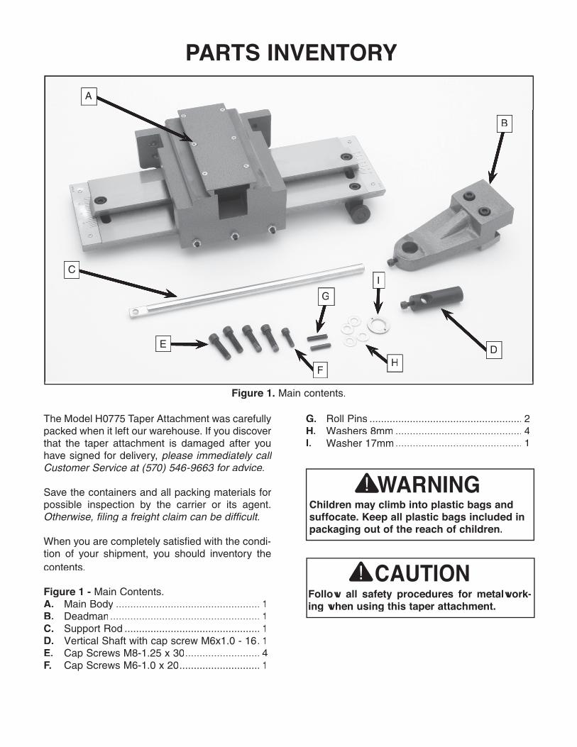
The Model H0775 Taper Attachment was carefully packed when it left our warehouse. If you discover that the taper attachment is damaged after you have signed for delivery, please immediately call Customer Service at (570) 546-9663 for advice.
Save the containers and all packing materials for possible inspection by the carrier or its agent. Otherwise, filing a freight claim can be difficult.
When you are completely satisfied with the condi-tion of your shipment, you should inventory the contents.
Figure 1 - Main Contents.A. Main Body .................................................. 1B. Deadman .................................................... 1C. Support Rod ............................................... 1D. Vertical Shaft with cap screw M6x1.0 - 16 . 1E. Cap Screws M8-1.25 x 30 .......................... 4F. Cap Screws M6-1.0 x 20 ............................ 1
Figure 1. Main contents.
Follow all safety procedures for metalwork-ing when using this taper attachment.
Children may climb into plastic bags and suffocate. Keep all plastic bags included in packaging out of the reach of children.
A
E
F
C
B
D
G
H
I
G. Roll Pins ..................................................... 2H. Washers 8mm ............................................ 4I. Washer 17mm ............................................ 1
INSTALLATION INSTRUCTIONSThe H0775 Taper Attachment mounts quickly to the back bed way of the G4016 Gear Head Lathe. Accurate tapers of up to 12" can be produced without repositioning the attachment. The H0775 features scales at both ends, reading inches-per-foot and degrees. An angle adjusting screw with fine threads achieves exacting control when set-ting tapers. Another feature is the ability to use it without disengaging the cross slide nut. This will allow it to be functional at any time by simply tightening the deadman.
The H0775 comes carefully packaged and it is coated with import grease to protect it from rust. You will need to clean all pieces thoroughly prior to installation and use. Use a solvent cleaner or citrus-based degreaser, like Grizzly's G7895 Citrus Degreaser. For optimum performance from your machine, make sure you clean all moving parts or sliding contact surfaces that are coated. Avoid chlorine-based solvents and gasoline as they may damage painted surfaces should they come in contact. Always follow the manufacturer’s instructions when using any type of cleaning product.
Installing the Taper Attachment1. Disconnect the lathe from its power
source.
2. Remove the splash guard from the back of the lathe. If the lathe must be moved to allow access to the splash guard, consult the lathe manual for safe moving information. Note: If you move the lathe, be sure to re-level it after returning the lathe to its final location.
Figure 3. Lathe component identification.
Locking NutStar
Washer
Spacer
Thrust Bearing
Bearing Dust Cover
Bearing Housing
4. Remove the spacer, bearing dust cover and thrust bearing from the end of the lead screw.
5. Remove the two cap screws that hold the bearing housing, along with the housing. Leave the remaining thrust bearing on the lead screw.
Lead Screw
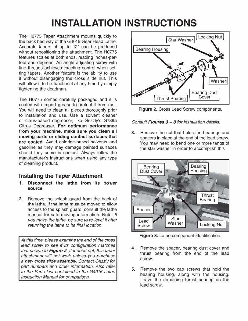
Consult Figures 3 – 8 for installation details.Figures 3 – 8 for installation details.Figures 3 – 8
3. Remove the nut that holds the bearings and spacers in place at the end of the lead screw. You may need to bend one or more tangs of the star washer in order to accomplish this
At this time, please examine the end of the cross lead screw to see if its configuration matches that shown in Figure 2. If it does not, this taper attachment will not work unless you purchase a new cross silde assembly. Contact Grizzly for part numbers and order information. Also refer to the Parts List contained in the G4016 Lathe Instruction Manual for comparison.
Figure 2. Cross Lead Screw components.
Locking NutStar Washer
Washer
Bearing Dust Cover
Bearing Housing
Thrust Bearing
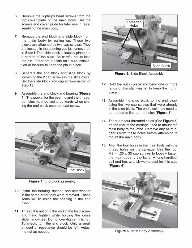
Figure 5. Slide Block Assembly.
6. Remove the 6 philips head screws from the top cover plate of the main body. Set the screws and cover aside for later use in reas-sembling the main body.
7. Remove the end block and slide block from the main body by pulling up. These two blocks are attached by two cap screws. They are located in the opening you just uncovered in Step 6.The slide block is loosely pinned to a portion of the slide. Be careful not to lose the pin. Either set it aside for future installa-tion or be sure to keep the pin in place.
8. Separate the end block and slide block by loosening the 2 cap screws in the slide block. Set the slide block and cap screws aside for step 13.
9. Assemble the end block and bearing (Figure 4). The pocket for the bearing and the thread-ed holes must be facing outwards when slid-ing the end block onto the lead screw.
10. Install the bearing, spacer, and star washer in the same order they were removed. These items will fit inside the opening in the end block.
11. Thread the nut onto the end of the lead screw and hand tighten while holding the cross slide handwheel. Do not over-tighten this nut. To check, turn the end block. Only a small amount of resistance should be felt. Adjust the nut as needed.
Slide Block
12. Hold the nut in place and bend one or more tangs of the star washer to keep the nut in place.
13. Assemble the slide block to the end block using the two cap screws that were already in the slide block. The end block may need to be rotated to line up the holes (Figure 5).
14. There are four threaded holes (See Figure 5) on the rear of the carriage used to mount the main body to the lathe. Remove any paint or debris from these holes before attemping to mount the main body.
15. Align the four holes in the main body with the thread holes on the carriage. Use the four M8 - 1.25 x 30 cap screws to loosely fasten the main body to the lathe. A long-handled, ball end hex wrench works best for this step (Figure 6).
Threaded Holes
Figure 4. End block assembly.
End Block
Figure 6. Main Body Assembly.
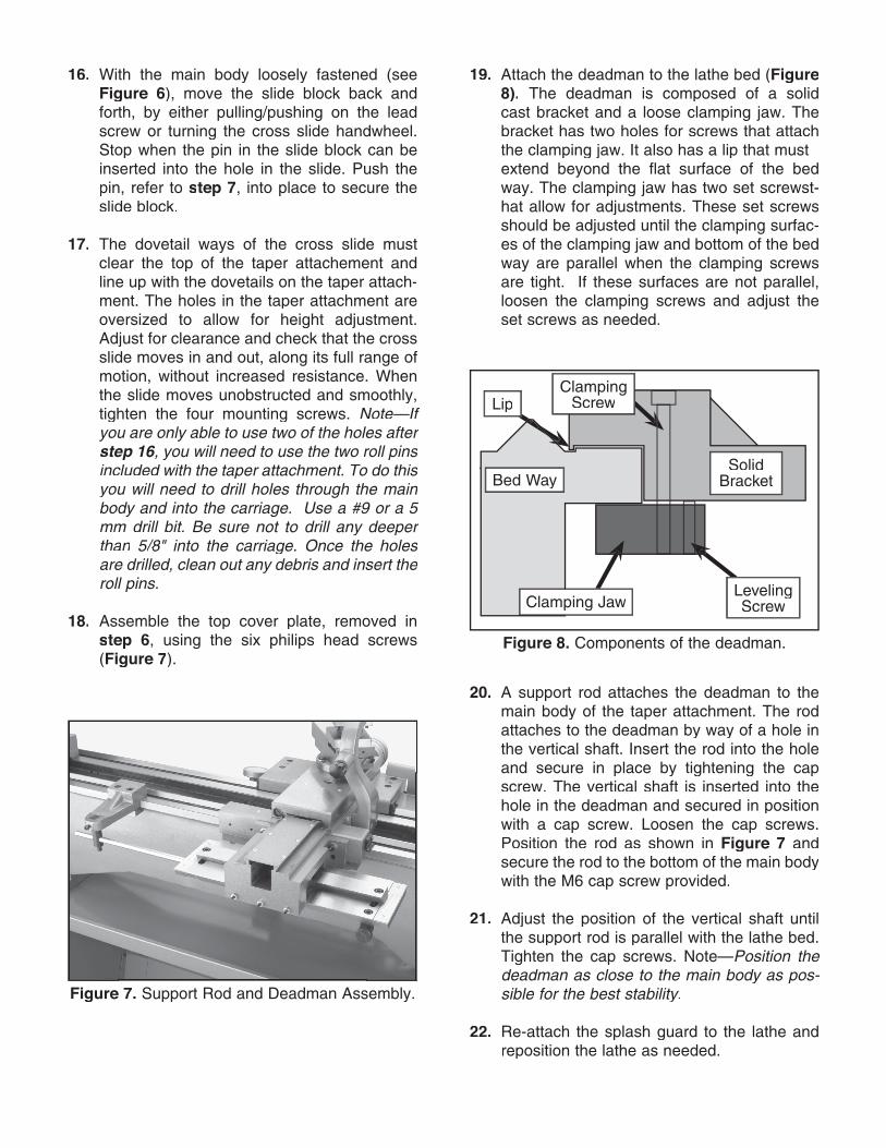
Figure 7. Support Rod and Deadman Assembly.
16. With the main body loosely fastened (see Figure 6), move the slide block back and forth, by either pulling/pushing on the lead screw or turning the cross slide handwheel. Stop when the pin in the slide block can be inserted into the hole in the slide. Push the pin, refer to step 7, into place to secure the slide block.
17. The dovetail ways of the cross slide must clear the top of the taper attachement and line up with the dovetails on the taper attach-ment. The holes in the taper attachment are oversized to allow for height adjustment. Adjust for clearance and check that the cross slide moves in and out, along its full range of motion, without increased resistance. When the slide moves unobstructed and smoothly, tighten the four mounting screws. Note—If you are only able to use two of the holes after step 16, you will need to use the two roll pins tep 16, you will need to use the two roll pins tep 16included with the taper attachment. To do this you will need to drill holes throughyou will need to drill holes throughy the main ou will need to drill holes through the main ou will need to drill holes throughbody and into the carriage. Use a arriage. Use a arr #9 or a 5 mm drill bit. Be sure not to drill any deeper than 5/5/5 8/8/ " into the carriage. Once the holes are drilled, clean out any debris and insert the roll pins.
18. Assemble the top cover plate, removed in step 6, using the six philips head screws (Figure 7).
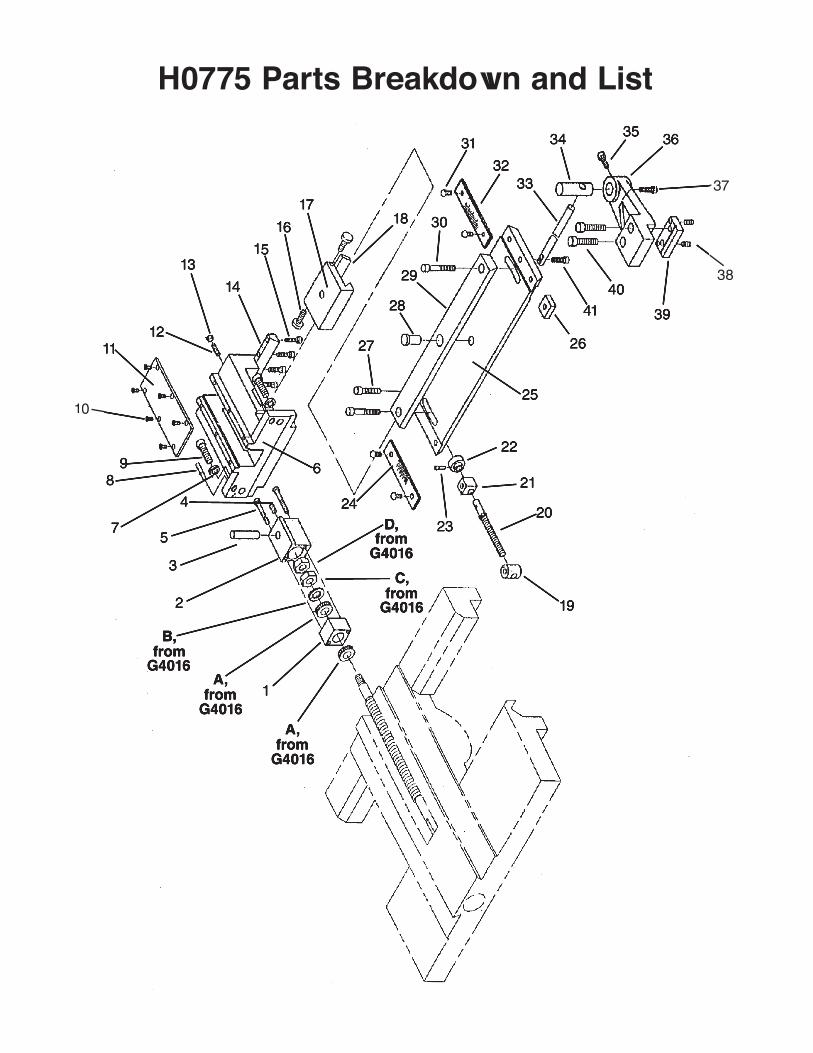
Figure 8. Components of the deadman.
Bed Way
Clamping JawLeveling Screw
Solid Bracket
LipClamping
Screw
20. A support rod attaches the deadman to the main body of the taper attachment. The rod attaches to the deadman by way of a hole in the vertical shaft. Insert the rod into the hole and secure in place by tightening the cap screw. The vertical shaft is inserted into the hole in the deadman and secured in position with a cap screw. Loosen the cap screws. Position the rod as shown in Figure 7 and secure the rod to the bottom of the main body with the M6 cap screw provided.
21. Adjust the position of the vertical shaft until the support rod is parallel with the lathe bed. Tighten the cap screws. Note—Position the deadman as close to the main body as pos-sible for the best stability.sible for the best stability.sible for the best stability
22. Re-attach the splash guard to the lathe and reposition the lathe as needed.
19. Attach the deadman to the lathe bed (Figure 8). The deadman is composed of a solid cast bracket and a loose clamping jaw. The bracket has two holes for screws that attach the clamping jaw. It also has a lip that must extend beyond the flat surface of the bed way. The clamping jaw has two set screwst-hat allow for adjustments. These set screws should be adjusted until the clamping surfac-es of the clamping jaw and bottom of the bed way are parallel when the clamping screws are tight. If these surfaces are not parallel, loosen the clamping screws and adjust the set screws as needed.

Angle AdjustmentsThe taper angle is adjusted by loosening the two cap screws at the ends of the dovetail slide on the taper attachment. The angle adjusting knob allows for fine control of the angle (Figure 9). There are two scales, one at each end of the main body. One is labeled for degrees and the other is labeled for inches-per-foot (I.P.F.). Using these scales will allow you to get close to the desired taper, but finer adjustments should be made with an indicator and test bar. Once the desired setting is met, tighten the two cap screws. Double check the setting to ensure accuracy.
OPERATION & ADJUSTMENTS
Figure 9. Taper Attachment Adjustments.
3. There are two gib screws, for making adjust-ments, located just above and behind the dovetail on the main body. To tighten the gib, loosen the gib screw on the left (as viewed from the front of the lathe) and tighten the right screw. To loosen the gib, loosen the right screw and tighten the left screw.
4. The gib is properly adjusted when the slide can be moved by hand with moderate force.
5. Do not replace the support rod at this time.
Bottom Gib AdjustmentsThe bottom gib is mounted in the back inside edge of the main body casting. Three set screws hold it in place and are secured with nuts as shown in Figure 9. If the gib is too loose, finish problems will occur. If the gib is too tight, the slide will not move smoothly.
1. Loosen the three nuts and apply tension evenly to the three set screws. Use only moderate pressure when tightening these set screws. They should be tight enough to keep the slide from rocking in the main body cast-ing. Check by rocking the slide by hand.
2. When satisfied with your results, tighten the nuts while maintaining the set screw posi-tion. Double check the slide to ensure that it moves smoothly. Re-adjust if necessary.
3. Re-attach the support rod to the main body.
Deadman OperationTo use the taper attachment, tighten the clamp-ing screws on the deadman to secure it to the lathe bed. When not in use, loosen the clamping screws. Removal of the deadman or the taper attachment is not necessary when changing from taper turning to straight turning.
Angle Adjusting Knob
Bottom Gib Screws
Angle Lock Screws
Top Gib AdjustmentsThe top gib is mounted to a slide and moves along the dovetail on the main body. The slide maintains the motion of the cross slide to produce the taper. If the gib is too loose, the angle can be affected and the finish will suffer. If the gib is too tight, the slide will not move freely.
1. To adjust the top gib, begin by removing the cap screw that holds the support rod to the main body.
2. Adjust the dovetail angle to zero.
H0775 Parts Breakdown and List
1
2
3
4
5
6
7
89
10
111112
13
14
15
16
A,from
G4016
1718
19
20
21
22
23
24
25
2627
28
29
30
31
3233
34 35 36
37
38
39
40
41
A,A,from
G4016
B,from
G4016
C,from
G4016
D,from
G4016

REF PART # DESCRIPTIONREF PART # DESCRIPTION20 PH0775020 THREADED ROD21 PH0775021 SUPPORTING BLOCK22 PH0775022 HANDLE23 PH0775023 PIN 3 X 1824 PH0775024 SIGN PLATE25 PH0775025 COPYING MODE26 PH0775026 MOVING BLOCK27 PSB13M CAP SCREW M8-1.25 X 3028 PH0775028 POSITIONING SCREW29 PH0775029 COPYING PLATE30 PSB13M CAP SCREW M8-1.25 X 3031 PH0775031 PHLP HD SCR M3-.5 X 832 PH0775032 SIGN PLATE33 PH0775033 SUPPORTING ROD34 PH0775034 VERTICAL ROD35 PSB01M CAP SCREW M6-1 X 1636 PH0775036 BRACKET37 PSB01M CAP SCREW M6-1 X 1638 PSS11M SET SCREW M6-1 X 1639 PH0775039 CLAMPING PLATE40 PSB45M CAP SCREW M8-1.25 X 4541 PSB02M CAP SCREW M6-1 X 20
A P51101 THRUST BEARING 51101B PH4016447 SPACER M12 X 8C PH4016448 STAR WASHER M12D PLN09 LOCKING NUT M12-1.251 PH0775001 END BLOCK2 PH0775002 SLIDE BLOCK3 PH0775003 PIN 12 X 504 PSS16M SET SCREW M8-1.25 X 10⁵ PH0775005 CAP SCREW M5-.8 X 456 PH0775006 MAIN BRACKET7 PW01M FLAT WASHER, 8MM8 PH0775008 PIN 5 X 259 PSB13M CAP SCREW M8-1.25 X 3010 PS07M PHLP HD SCR M4-.7 X 811 PH0775011 COVER12 PSS25M SET SCREW M6-1 X 2013 PN01M HEX NUT M6-114 PH0775014 SLANT IRON15 PSB06M CAP SCREW M6-1 X 2516 PH0775016 ADJUSTING BLOCK17 PH0775017 SLIDE18 PH0775018 GIB19 PH0775019 ROUND NUT
H0775 Parts List
A P51101 THRUST BEARING 51101B PH4016447 SPACER M12 X 8C PH4016448 STAR WASHER M12D PLN09 LOCKING NUT M12-1.251 PH0775001 END BLOCK2 PH0775002 SLIDE BLOCK3 PH0775003 PIN 12 X 504 PSS16M SET SCREW M8-1.25 X 10⁵ PH0775005 CAP SCREW M5-.8 X 456 PH0775006 MAIN BRACKET7 PW01M FLAT WASHER, 8MM8 PH0775008 PIN 5 X 259 PSB13M CAP SCREW M8-1.25 X 3010 PS07M PHLP HD SCR M4-.7 X 811 PH0775011 COVER12 PSS25M SET SCREW M6-1 X 2013 PN01M HEX NUT M6-114 PH0775014 SLANT IRON15 PSB06M CAP SCREW M6-1 X 2516 PH0775016 ADJUSTING BLOCK17 PH0775017 SLIDE18 PH0775018 GIB19 PH0775019 ROUND NUT
A P51101 THRUST BEARING 51101B PH4016447 SPACER M12 X 8C PH4016448 STAR WASHER M12D PLN09 LOCKING NUT M12-1.251 PH0775001 END BLOCK2 PH0775002 SLIDE BLOCK3 PH0775003 PIN 12 X 504 PSS16M SET SCREW M8-1.25 X 10⁵ PH0775005 CAP SCREW M5-.8 X 456 PH0775006 MAIN BRACKET7 PW01M FLAT WASHER, 8MM8 PH0775008 PIN 5 X 259 PSB13M CAP SCREW M8-1.25 X 3010 PS07M PHLP HD SCR M4-.7 X 811 PH0775011 COVER12 PSS25M SET SCREW M6-1 X 2013 PN01M HEX NUT M6-114 PH0775014 SLANT IRON15 PSB06M CAP SCREW M6-1 X 2516 PH0775016 ADJUSTING BLOCK17 PH0775017 SLIDE18 PH0775018 GIB19 PH0775019 ROUND NUT
20 PH0775020 THREADED ROD21 PH0775021 SUPPORTING BLOCK22 PH0775022 HANDLE23 PH0775023 PIN 3 X 1824 PH0775024 SIGN PLATE25 PH0775025 COPYING MODE26 PH0775026 MOVING BLOCK27 PSB13M CAP SCREW M8-1.25 X 3028 PH0775028 POSITIONING SCREW29 PH0775029 COPYING PLATE
31 PH0775031 PHLP HD SCR M3-.5 X 832 PH0775032 SIGN PLATE33 PH0775033 SUPPORTING ROD34 PH0775034 VERTICAL ROD35 PSB01M CAP SCREW M6-1 X 1636 PH0775036 BRACKET
38 PSS11M SET SCREW M6-1 X 1639 PH0775039 CLAMPING PLATE40 PSB45M CAP SCREW M8-1.25 X 4541 PSB02M CAP SCREW M6-1 X 20
20 PH0775020 THREADED ROD21 PH0775021 SUPPORTING BLOCK22 PH0775022 HANDLE23 PH0775023 PIN 3 X 1824 PH0775024 SIGN PLATE25 PH0775025 COPYING MODE26 PH0775026 MOVING BLOCK27 PSB13M CAP SCREW M8-1.25 X 3028 PH0775028 POSITIONING SCREW29 PH0775029 COPYING PLATE
PSB13M CAP SCREW M8-1.25 X 3031 PH0775031 PHLP HD SCR M3-.5 X 832 PH0775032 SIGN PLATE33 PH0775033 SUPPORTING ROD34 PH0775034 VERTICAL ROD35 PSB01M CAP SCREW M6-1 X 1636 PH0775036 BRACKET
PSB01M CAP SCREW M6-1 X 1638 PSS11M SET SCREW M6-1 X 1639 PH0775039 CLAMPING PLATE40 PSB45M CAP SCREW M8-1.25 X 4541 PSB02M CAP SCREW M6-1 X 20