Embed Size (px)
Citation preview
Answers for energy.
www.siemens.com/energy
GEAFOL Cast-Resin Transformers 100 to 16,000 kVACatalog TV1 | 2013
Contents
Transformer Technology at a Glance 4
Selection and Ordering Data 5
Connection System 10
Temperature Supervision, Forced-Air Cooling 11
Standard Housings 12
Selection of Housings 13
Special Housings, Dimensions 14
The products and systems described in this catalog are manufactured and sold according to a certified quality and environmental management system (acc. to ISO 9001, ISO 14001 and BS OHSAS 18001:2007). DNV certificate nos. 124016-2012-AHSO-GER-TGA and 130462-2013-AHSO-GER-TGA. The certificate is accepted in all IQNet countries.
Supersedes: Catalog TV1 · 2008
2
The Safe TechnologyGEAFOL Cast-Resin Transformers
Wherever distribution transformers have to assure the utmost safety in areas frequented by people, GEAFOL® cast-resin transformers are the ideal solution. With GEAFOL, the limitations of liquid-filled transformers are avoided, but the proven characteristics such as operating safety and service life are retained.
GEAFOL cast-resin trans formers comply with IEC 60076-11 or DIN EN 60076-11 and VDE 0532-76-11. However, they can also be designed to meet special national regulations or customer wishes; for example, GEAFOL transformers can be manufactured in compliance with IEEE Std C57.12.01, CAN/CSA-C22.2 No. 47-M90, and UL 1562. GEAFOL trans-formers are certified by UL, CSA, and TÜV. Even the Russian GOST standards can be met. We offer tailored solutions that meet all requirements when it comes to operating mode, low noise and loss levels, connection technology, type of cooling, as well as transport and installation.
Safety proven 100,000 times overThere are good reasons why GEAFOL cast-resin transformers are used wherever absolute safety is required. They can be found in high-rise buildings, hospitals, road and under-ground railway shafts, offshore installations, mines, wind turbines, nuclear power plants, and many other safety-critical environments. It is not surprising that the superior GEAFOL technology is produced under license by many transformer manufacturers all over the world.
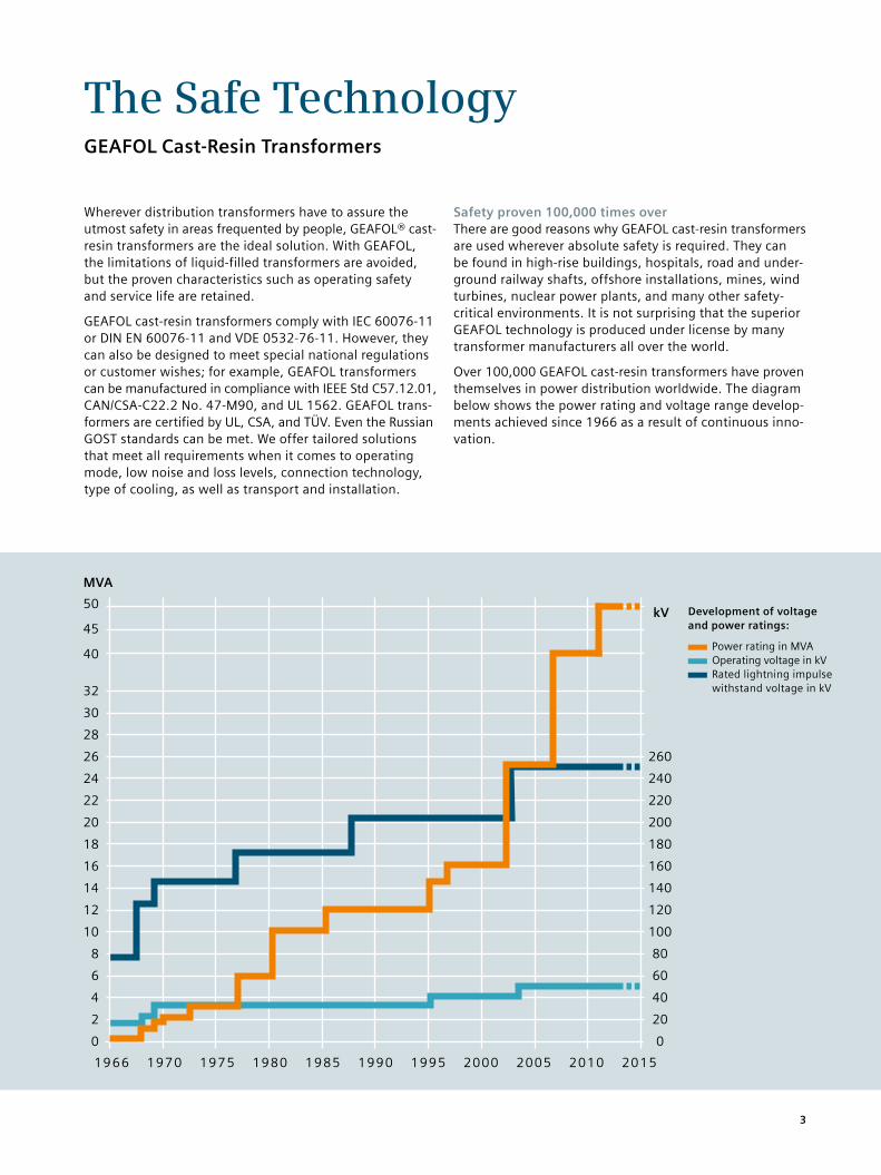
Over 100,000 GEAFOL cast-resin transformers have proven themselves in power distribution worldwide. The diagram below shows the power rating and voltage range develop-ments achieved since 1966 as a result of continuous inno-vation.
Development of voltage and power ratings:
Power rating in MVA Operating voltage in kV Rated lightning impulse withstand voltage in kV
50
45
40
32
30
28
26
24
22
20
18
16
14
12
10
8
6
4
2
0
1966 1970 1975 1980 1985 1990 1995 2000 2005 2010 2015
260
240
220
200
180
160
140
120
100
80
60
40
20
0
MVA
kV
3
Transformatorentechnik auf einen Blick
5
9
8
7
61
2
3
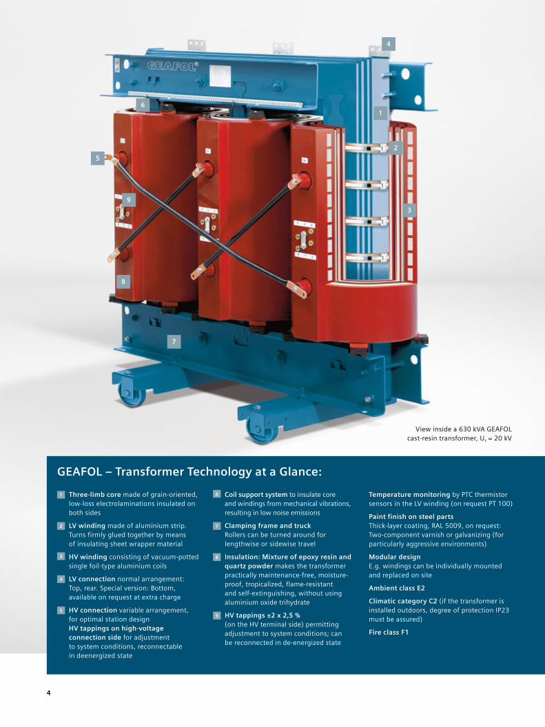
View inside a 630 kVA GEAFOL cast-resin transformer, Ur = 20 kV
4
GEAFOL – Transformer Technology at a Glance:
1 Three-limb core made of grain-oriented, low-loss electrolaminations insulated on both sides
2 LV winding made of aluminium strip. Turns firmly glued together by means of insulating sheet wrapper material
3 HV winding consisting of vacuum-potted single foil-type aluminium coils
4 LV connection normal arrangement: Top, rear. Special version: Bottom, available on request at extra charge
5 HV connection variable arrangement, for optimal station design HV tappings on high-voltage connection side for adjustment to system conditions, reconnectable in deenergized state
6 Coil support system to insulate core and windings from mechanical vibrations, resulting in low noise emissions
7 Clamping frame and truck Rollers can be turned around for lengthwise or sidewise travel
8 Insulation: Mixture of epoxy resin and quartz powder makes the transformer practically maintenance-free, moisture-proof, tropicalized, flame-resistant and self-extinguishing, without using aluminium oxide trihydrate
9 HV tappings ±2 x 2,5 % (on the HV terminal side) permitting adjustment to system conditions; can be reconnected in de-energized state
Temperature monitoring by PTC thermistor sensors in the LV winding (on request PT 100)
Paint finish on steel parts Thick-layer coating, RAL 5009, on request: Two-component varnish or galvanizing (for particularly aggressive environments)
Modular design E.g. windings can be individually mounted and replaced on site
Ambient class E2
Climatic category C2 (if the transformer is installed outdoors, degree of protection IP23 must be assured)
Fire class F1
4
1) Applies to Ur HV: 10 to 12 kV 20 to 24 kV 30 to 36 kV
2) Dimension drawing: page 15, indications are approximate values
3) Indication of 0.4 kV applies to the voltage range of 0.4–0.45 kV
4) Ratings in brackets are not standardized
Selection and Ordering DataR
ated
po
wer
Rat
ed p
rim
ary
volt
age1
) ta
pp
ing
± 2
x 2
.5 %
Rat
ed s
eco
nd
ary
vo
ltag
e3) (
no
-lo
ad)
Insu
lati
on
leve
l HV
(A
C/L
I)
Insu
lati
on
leve
l LV
(A
C/L
I)
Imp
edan
ce v
olt
age
at
rat
ed c
urr
ent
No
-lo
ad lo
sses
Load
loss
es a
t 1
20
°C
No
ise
leve
l
Order No. Tota
l wei
gh
t
Len
gth
Wid
th
Hei
gh
t
Sr
kVA
Ur HV kV
Ur LV kV
kV
kV
uzr %
Po
W
Pk120
W
LWA
dB
approx.
kg
a2)
mm
b2)
mm
h2)
mm
100 10 0.4 28/ 75 3/– 4 440 1850 59 4GB5044-3CY05-0AA2 600 1210 670 84010 0.4 28/ 75 3/– 4 320 1850 51 4GB5044-3GY05-0AA2 720 1230 675 84510 0.4 28/ 75 3/– 6 360 2000 59 4GB5044-3DY05-0AA2 570 1200 680 80510 0.4 28/ 75 3/– 6 290 2000 51 4GB5044-3HY05-0AA2 720 1280 685 89020 0.4 50/ 95 3/– 4 600 1750 59 4GB5064-3CY05-0AA2 620 1220 740 92520 0.4 50/ 95 3/– 4 400 1750 51 4GB5064-3GY05-0AA2 740 1260 745 94520 0.4 50/ 95 3/– 6 460 2050 59 4GB5064-3DY05-0AA2 610 1250 750 91520 0.4 50/ 95 3/– 6 340 2050 51 4GB5064-3HY05-0AA2 730 1280 750 94020 0.4 50/125 3/– 6 460 2050 59 4GB5067-3DY05-0AA2 720 1260 750 1145
160 10 0.4 28/ 75 3/– 4 610 2600 62 4GB5244-3CY05-0AA2 820 1270 690 102510 0.4 28/ 75 3/– 4 440 2600 54 4GB5244-3GY05-0AA2 960 1260 685 110010 0.4 28/ 75 3/– 6 500 2750 62 4GB5244-3DY05-0AA2 690 1220 685 99010 0.4 28/ 75 3/– 6 400 2750 54 4GB5244-3HY05-0AA2 850 1290 695 101020 0.4 50/ 95 3/– 4 870 2500 62 4GB5264-3CY05-0AA2 790 1280 745 106020 0.4 50/ 95 3/– 4 580 2500 54 4GB5264-3GY05-0AA2 920 1320 755 106020 0.4 50/ 95 3/– 6 650 2700 62 4GB5264-3DY05-0AA2 780 1320 760 104020 0.4 50/ 95 3/– 6 480 2700 54 4GB5264-3HY05-0AA2 860 1350 765 105020 0.4 50/125 3/– 6 650 2900 62 4GB5267-3DY05-0AA2 870 1310 720 1200
250 10 0.4 28/ 75 3/– 4 820 3200 65 4GB5444-3CY05-0AA2 1010 1330 700 105510 0.4 28/ 75 3/– 4 600 3200 57 4GB5444-3GY05-0AA2 1250 1340 700 119010 0.4 28/ 75 3/– 6 700 3300 65 4GB5444-3DY05-0AA2 960 1340 705 105510 0.4 28/ 75 3/– 6 560 3300 57 4GB5444-3HY05-0AA2 1130 1390 715 107020 0.4 50/ 95 3/– 4 1100 3200 65 4GB5464-3CY05-0AA2 1070 1370 730 111520 0.4 50/ 95 3/– 4 800 3300 57 4GB5464-3GY05-0AA2 1230 1420 740 113020 0.4 50/ 95 3/– 6 880 3400 65 4GB5464-3DY05-0AA2 1020 1390 740 110520 0.4 50/ 95 3/– 6 650 3400 57 4GB5464-3HY05-0AA2 1190 1430 745 112520 0.4 50/125 3/– 6 880 3800 65 4GB5467-3DY05-0AA2 1070 1390 740 120030 0.4 70/145 3/– 6 1280 4000 67 4GB5475-3DY05-0AA2 1190 1450 825 1365
(315)4) 10 0.4 28/ 75 3/– 4 980 3500 67 4GB5544-3CY05-0AA2 1120 1340 820 113010 0.4 28/ 75 3/– 4 730 3500 59 4GB5544-3GY05-0AA2 1400 1400 820 119510 0.4 28/ 75 3/– 6 850 3900 67 4GB5544-3DY05-0AA2 1130 1360 820 116010 0.4 28/ 75 3/– 6 670 3700 59 4GB5544-3HY05-0AA2 1260 1400 820 117020 0.4 50/ 95 3/– 4 1250 3500 67 4GB5564-3CY05-0AA2 1370 1490 835 114520 0.4 50/ 95 3/– 4 930 3500 59 4GB5564-3GY05-0AA2 1590 1520 835 120520 0.4 50/ 95 3/– 6 1000 3800 67 4GB5564-3DY05-0AA2 1350 1490 835 118020 0.4 50/ 95 3/– 6 780 3800 59 4GB5564-3HY05-0AA2 1450 1520 840 120520 0.4 50/125 3/– 6 1000 4200 67 4GB5567-3DY05-0AA2 1430 1520 840 123530 0.4 70/145 3/– 6 1450 4700 69 4GB5575-3DY05-0AA2 1460 1510 915 1445
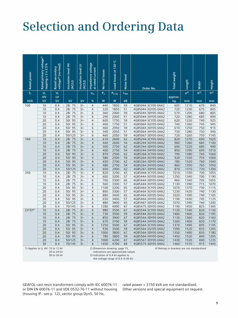
GEAFOL cast-resin transformers comply with IEC 60076-11 or DIN EN 60076-11 and VDE 0532-76-11 without housing (housing IP.. see p. 12), vector group Dyn5, 50 Hz,
rated power > 3150 kVA are not standardized. Other versions and special equipment on request.
5
1) Applies to Ur HV: 10 to 12 kV 20 to 24 kV 30 to 36 kV
2) Dimension drawing: page 15, indications are approximate values
3) Indication of 0.4 kV applies to the voltage range of 0.4–0.45 kV
4) Ratings in brackets are not standardized
Selection and Ordering DataR
ated
po
wer
Rat
ed p
rim
ary
volt
age1
) ta
pp
ing
± 2
x 2
.5 %
Rat
ed s
eco
nd
ary
vo
ltag
e3) (
no
-lo
ad)
Insu
lati
on
leve
l HV
(A
C/L
I)
Insu
lati
on
leve
l LV
(A
C/L
I)
Imp
edan
ce v
olt
age
at
rat
ed c
urr
ent
No
-lo
ad lo
sses
Load
loss
es a
t 1
20
°C
No
ise
leve
l
Order No. Tota
l wei
gh
t
Len
gth
Wid
th
Hei
gh
t
Sr
kVA
Ur HV kV
Ur LV kV
kV
kV
uzr %
Po
W
Pk120
W
LWA
dB
approx.
kg
a2)
mm
b2)
mm
h2)
mm
400 10 0.4 28/ 75 3/– 4 1150 4400 68 4GB5644-3CY05-0AA2 1290 1370 820 123010 0.4 28/ 75 3/– 4 880 4400 60 4GB5644-3GY05-0AA2 1500 1390 820 133010 0.4 28/ 75 3/– 6 1000 4900 68 4GB5644-3DY05-0AA2 1230 1400 820 121510 0.4 28/ 75 3/– 6 800 4900 60 4GB5644-3HY05-0AA2 1390 1430 820 123020 0.4 50/ 95 3/– 4 1450 3800 68 4GB5664-3CY05-0AA2 1470 1460 830 128520 0.4 50/ 95 3/– 4 1100 3800 60 4GB5664-3GY05-0AA2 1710 1520 835 130520 0.4 50/ 95 3/– 6 1200 4300 68 4GB5664-3DY05-0AA2 1380 1490 835 126020 0.4 50/ 95 3/– 6 940 4300 60 4GB5664-3HY05-0AA2 1460 1500 840 126020 0.4 50/125 3/– 6 1200 4700 68 4GB5667-3DY05-0AA2 1530 1540 845 131030 0.4 70/145 3/– 6 1650 5500 69 4GB5675-3DY05-0AA2 1590 1560 925 1500
(500)4) 10 0.4 28/ 75 3/– 4 1300 5900 69 4GB5744-3CY05-0AA0 1490 1410 820 131510 0.4 28/ 75 3/– 4 1000 5300 61 4GB5744-3GY05-0AA0 1620 1420 820 134010 0.4 28/ 75 3/– 6 1200 6400 69 4GB5744-3DY05-0AA0 1420 1450 820 124510 0.4 28/ 75 3/– 6 950 6400 61 4GB5744-3HY05-0AA0 1540 1490 820 126520 0.4 50/ 95 3/– 4 1700 4900 69 4GB5764-3CY05-0AA0 1550 1460 840 136520 0.4 50/ 95 3/– 4 1300 4900 61 4GB5764-3GY05-0AA0 1700 1490 845 137020 0.4 50/ 95 3/– 6 1400 5100 69 4GB5764-3DY05-0AA0 1500 1530 855 127520 0.4 50/ 95 3/– 6 1100 5100 61 4GB5764-3HY05-0AA0 1670 1560 860 129020 0.4 50/125 3/– 6 1400 6300 69 4GB5767-3DY05-0AA0 1610 1540 855 135530 0.4 70/145 3/– 6 1900 6000 70 4GB5775-3DY05-0AA0 1810 1560 925 161530 0.4 70/170 3/– 6 2600 6200 79 4GB5780-3DY05-0AA0 2110 1710 1005 1590
630 10 0.4 28/ 75 3/– 4 1500 7300 70 4GB5844-3CY05-0AA0 1670 1410 820 148510 0.4 28/ 75 3/– 4 1150 7300 62 4GB5844-3GY05-0AA0 1840 1440 820 148510 0.4 28/ 75 3/– 6 1370 7500 70 4GB5844-3DY05-0AA0 1710 1520 830 130510 0.4 28/ 75 3/– 6 1100 7500 62 4GB5844-3HY05-0AA0 1850 1560 835 133020 0.4 50/ 95 3/– 4 2000 6900 70 4GB5864-3CY05-0AA0 1790 1470 840 153020 0.4 50/ 95 3/– 4 1600 6900 62 4GB5864-3GY05-0AA0 1930 1520 845 156520 0.4 50/ 95 3/– 6 1650 6800 70 4GB5864-3DY05-0AA0 1750 1560 860 136520 0.4 50/ 95 3/– 6 1250 6800 62 4GB5864-3HY05-0AA0 1900 1600 865 138520 0.4 50/125 3/– 6 1650 7000 70 4GB5867-3DY05-0AA0 1830 1590 865 139530 0.4 70/145 3/– 6 2200 6600 71 4GB5875-3DY05-0AA0 2090 1620 940 1640
800 10 0.4 28/ 75 3/– 4 1800 7800 72 4GB5944-3CY05-0AA0 1970 1500 820 153510 0.4 28/ 75 3/– 4 1400 7800 64 4GB5944-3GY05-0AA0 2210 1530 825 153510 0.4 28/ 75 3/– 6 1700 8300 72 4GB5944-3DY05-0AA0 2020 1590 840 139510 0.4 28/ 75 3/– 6 1300 8300 64 4GB5944-3HY05-0AA0 2230 1620 845 139520 0.4 50/ 95 3/– 4 2400 8500 72 4GB5964-3CY05-0AA0 2020 1550 850 159520 0.4 50/ 95 3/– 4 1900 8500 64 4GB5964-3GY05-0AA0 2220 1570 855 159520 0.4 50/ 95 3/– 6 1900 8200 72 4GB5964-3DY05-0AA0 2020 1610 870 143520 0.4 50/ 95 3/– 6 1500 8200 64 4GB5964-3HY05-0AA0 2220 1650 875 145520 0.4 50/125 3/– 6 1900 9400 72 4GB5967-3DY05-0AA0 2160 1660 880 148530 0.4 70/145 3/– 6 2650 7900 72 4GB5975-3DY05-0AA0 2620 1740 965 1695
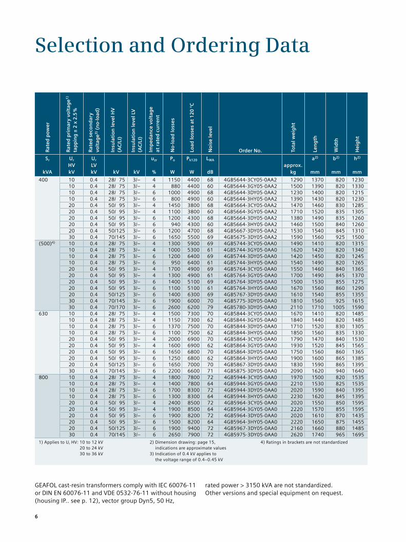
GEAFOL cast-resin transformers comply with IEC 60076-11 or DIN EN 60076-11 and VDE 0532-76-11 without housing (housing IP.. see p. 12), vector group Dyn5, 50 Hz,
rated power > 3150 kVA are not standardized. Other versions and special equipment on request.
6
1) Applies to Ur HV: 10 to 12 kV 20 to 24 kV 30 to 36 kV
2) Dimension drawing: page 15, indications are approximate values
3) Indication of 0.4 kV applies to the voltage range of 0.4–0.45 kV
4) Ratings in brackets are not standardized
Selection and Ordering DataR
ated
po
wer
Rat
ed p
rim
ary
volt
age1
) ta
pp
ing
± 2
x 2
.5 %
Rat
ed s
eco
nd
ary
vo
ltag
e3) (
no
-lo
ad)
Insu
lati
on
leve
l HV
(A
C/L
I)
Insu
lati
on
leve
l LV
(A
C/L
I)
Imp
edan
ce v
olt
age
at
rat
ed c
urr
ent
No
-lo
ad lo
sses
Load
loss
es a
t 1
20
°C
No
ise
leve
l
Order No. Tota
l wei
gh
t
Len
gth
Wid
th
Hei
gh
t
Sr
kVA
Ur HV kV
Ur LV kV
kV
kV
uzr %
Po
W
Pk120
W
LWA
dB
approx.
kg
a2)
mm
b2)
mm
h2)
mm
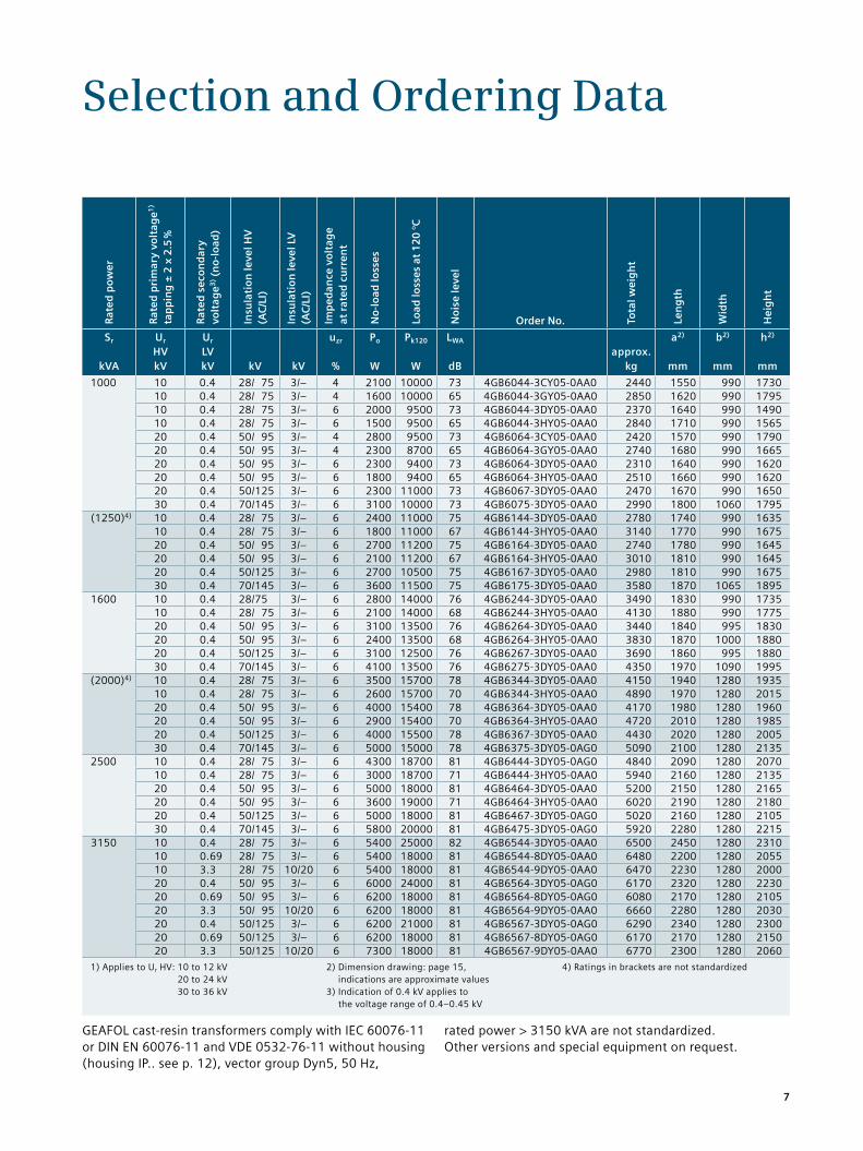
1000 10 0.4 28/ 75 3/– 4 2100 10000 73 4GB6044-3CY05-0AA0 2440 1550 990 173010 0.4 28/ 75 3/– 4 1600 10000 65 4GB6044-3GY05-0AA0 2850 1620 990 179510 0.4 28/ 75 3/– 6 2000 9500 73 4GB6044-3DY05-0AA0 2370 1640 990 149010 0.4 28/ 75 3/– 6 1500 9500 65 4GB6044-3HY05-0AA0 2840 1710 990 156520 0.4 50/ 95 3/– 4 2800 9500 73 4GB6064-3CY05-0AA0 2420 1570 990 179020 0.4 50/ 95 3/– 4 2300 8700 65 4GB6064-3GY05-0AA0 2740 1680 990 166520 0.4 50/ 95 3/– 6 2300 9400 73 4GB6064-3DY05-0AA0 2310 1640 990 162020 0.4 50/ 95 3/– 6 1800 9400 65 4GB6064-3HY05-0AA0 2510 1660 990 162020 0.4 50/125 3/– 6 2300 11000 73 4GB6067-3DY05-0AA0 2470 1670 990 165030 0.4 70/145 3/– 6 3100 10000 73 4GB6075-3DY05-0AA0 2990 1800 1060 1795
(1250)4) 10 0.4 28/ 75 3/– 6 2400 11000 75 4GB6144-3DY05-0AA0 2780 1740 990 163510 0.4 28/ 75 3/– 6 1800 11000 67 4GB6144-3HY05-0AA0 3140 1770 990 167520 0.4 50/ 95 3/– 6 2700 11200 75 4GB6164-3DY05-0AA0 2740 1780 990 164520 0.4 50/ 95 3/– 6 2100 11200 67 4GB6164-3HY05-0AA0 3010 1810 990 164520 0.4 50/125 3/– 6 2700 10500 75 4GB6167-3DY05-0AA0 2980 1810 990 167530 0.4 70/145 3/– 6 3600 11500 75 4GB6175-3DY05-0AA0 3580 1870 1065 1895
1600 10 0.4 28/75 3/– 6 2800 14000 76 4GB6244-3DY05-0AA0 3490 1830 990 173510 0.4 28/ 75 3/– 6 2100 14000 68 4GB6244-3HY05-0AA0 4130 1880 990 177520 0.4 50/ 95 3/– 6 3100 13500 76 4GB6264-3DY05-0AA0 3440 1840 995 183020 0.4 50/ 95 3/– 6 2400 13500 68 4GB6264-3HY05-0AA0 3830 1870 1000 188020 0.4 50/125 3/– 6 3100 12500 76 4GB6267-3DY05-0AA0 3690 1860 995 188030 0.4 70/145 3/– 6 4100 13500 76 4GB6275-3DY05-0AA0 4350 1970 1090 1995
(2000)4) 10 0.4 28/ 75 3/– 6 3500 15700 78 4GB6344-3DY05-0AA0 4150 1940 1280 193510 0.4 28/ 75 3/– 6 2600 15700 70 4GB6344-3HY05-0AA0 4890 1970 1280 201520 0.4 50/ 95 3/– 6 4000 15400 78 4GB6364-3DY05-0AA0 4170 1980 1280 196020 0.4 50/ 95 3/– 6 2900 15400 70 4GB6364-3HY05-0AA0 4720 2010 1280 198520 0.4 50/125 3/– 6 4000 15500 78 4GB6367-3DY05-0AA0 4430 2020 1280 200530 0.4 70/145 3/– 6 5000 15000 78 4GB6375-3DY05-0AG0 5090 2100 1280 2135
2500 10 0.4 28/ 75 3/– 6 4300 18700 81 4GB6444-3DY05-0AG0 4840 2090 1280 207010 0.4 28/ 75 3/– 6 3000 18700 71 4GB6444-3HY05-0AA0 5940 2160 1280 213520 0.4 50/ 95 3/– 6 5000 18000 81 4GB6464-3DY05-0AA0 5200 2150 1280 216520 0.4 50/ 95 3/– 6 3600 19000 71 4GB6464-3HY05-0AA0 6020 2190 1280 218020 0.4 50/125 3/– 6 5000 18000 81 4GB6467-3DY05-0AG0 5020 2160 1280 210530 0.4 70/145 3/– 6 5800 20000 81 4GB6475-3DY05-0AG0 5920 2280 1280 2215
3150 10 0.4 28/ 75 3/– 6 5400 25000 82 4GB6544-3DY05-0AA0 6500 2450 1280 231010 0.69 28/ 75 3/– 6 5400 18000 81 4GB6544-8DY05-0AA0 6480 2200 1280 205510 3.3 28/ 75 10/20 6 5400 18000 81 4GB6544-9DY05-0AA0 6470 2230 1280 200020 0.4 50/ 95 3/– 6 6000 24000 81 4GB6564-3DY05-0AG0 6170 2320 1280 223020 0.69 50/ 95 3/– 6 6200 18000 81 4GB6564-8DY05-0AG0 6080 2170 1280 210520 3.3 50/ 95 10/20 6 6200 18000 81 4GB6564-9DY05-0AA0 6660 2280 1280 203020 0.4 50/125 3/– 6 6200 21000 81 4GB6567-3DY05-0AG0 6290 2340 1280 230020 0.69 50/125 3/– 6 6200 18000 81 4GB6567-8DY05-0AG0 6170 2170 1280 215020 3.3 50/125 10/20 6 7300 18000 81 4GB6567-9DY05-0AA0 6770 2300 1280 2060
GEAFOL cast-resin transformers comply with IEC 60076-11 or DIN EN 60076-11 and VDE 0532-76-11 without housing (housing IP.. see p. 12), vector group Dyn5, 50 Hz,
rated power > 3150 kVA are not standardized. Other versions and special equipment on request.
7
Selection and Ordering Data
1) Applies to Ur HV: 10 to 12 kV 20 to 24 kV 30 to 36 kV
2) Dimension drawing: page 15, indications are approximate values
GEAFOL cast-resin transformers comply with IEC 60076-11 or DIN EN 60076-11 and VDE 0532-76-11 without housing (housing IP.. see p. 12), vector group Dyn5, 50 Hz,
rated power > 3150 kVA are not standardized. Other versions and special equipment on request.
Rat
ed p
ow
er
Rat
ed p
rim
ary
volt
age1
) ta
pp
ing
± 2
x 2
.5 %
Rat
ed s
eco
nd
ary
vo
ltag
e (n
o-l
oad
)
Insu
lati
on
leve
l HV
(A
C/L
I)
Insu
lati
on
leve
l LV
(A
C/L
I)
Imp
edan
ce v
olt
age
at
rat
ed c
urr
ent
No
-lo
ad lo
sses
Load
loss
es a
t 1
20
°C
No
ise
leve
l
Order No. Tota
l wei
gh
t
Len
gth
Wid
th
Hei
gh
t
Sr
kVA
Ur HV kV
Ur LV kV
kV
kV
uzr %
Po
W
Pk120
W
LWA
dB
approx.
kg
a2)
mm
b2)
mm
h2)
mm
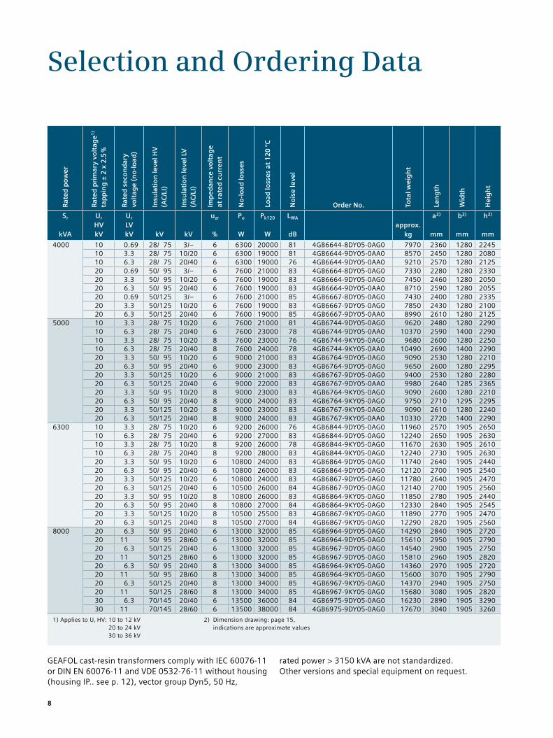
4000 10 0.69 28/ 75 3/– 6 6300 20000 81 4GB6644-8DY05-0AG0 7970 2360 1280 224510 3.3 28/ 75 10/20 6 6300 19000 81 4GB6644-9DY05-0AA0 8570 2450 1280 208010 6.3 28/ 75 20/40 6 6300 19000 76 4GB6644-9DY05-0AA0 9210 2570 1280 212520 0.69 50/ 95 3/– 6 7600 21000 83 4GB6664-8DY05-0AG0 7330 2280 1280 233020 3.3 50/ 95 10/20 6 7600 19000 83 4GB6664-9DY05-0AG0 7450 2460 1280 205020 6.3 50/ 95 20/40 6 7600 19000 83 4GB6664-9DY05-0AA0 8710 2590 1280 205520 0.69 50/125 3/– 6 7600 21000 85 4GB6667-8DY05-0AG0 7430 2400 1280 233520 3.3 50/125 10/20 6 7600 19000 83 4GB6667-9DY05-0AG0 7850 2430 1280 210020 6.3 50/125 20/40 6 7600 19000 85 4GB6667-9DY05-0AA0 8990 2610 1280 2125
5000 10 3.3 28/ 75 10/20 6 7600 21000 81 4GB6744-9DY05-0AG0 9620 2480 1280 229010 6.3 28/ 75 20/40 6 7600 23000 78 4GB6744-9DY05-0AA0 10370 2590 1400 229010 3.3 28/ 75 10/20 8 7600 23000 76 4GB6744-9KY05-0AG0 9680 2600 1280 225010 6.3 28/ 75 20/40 8 7600 24000 78 4GB6744-9KY05-0AA0 10490 2690 1400 229020 3.3 50/ 95 10/20 6 9000 21000 83 4GB6764-9DY05-0AG0 9090 2530 1280 221020 6.3 50/ 95 20/40 6 9000 23000 83 4GB6764-9DY05-0AG0 9650 2600 1280 229520 3.3 50/125 10/20 6 9000 21000 83 4GB6767-9DY05-0AG0 9400 2530 1280 228020 6.3 50/125 20/40 6 9000 22000 83 4GB6767-9DY05-0AA0 9980 2640 1285 236520 3.3 50/ 95 10/20 8 9000 23000 83 4GB6764-9KY05-0AG0 9090 2600 1280 221020 6.3 50/ 95 20/40 8 9000 24000 83 4GB6764-9KY05-0AG0 9750 2710 1295 229520 3.3 50/125 10/20 8 9000 23000 83 4GB6767-9KY05-0AG0 9090 2610 1280 224020 6.3 50/125 20/40 8 9000 24000 83 4GB6767-9KY05-0AA0 10330 2720 1400 2290
6300 10 3.3 28/ 75 10/20 6 9200 26000 76 4GB6844-9DY05-0AG0 11960 2570 1905 265010 6.3 28/ 75 20/40 6 9200 27000 83 4GB6844-9DY05-0AG0 12240 2650 1905 263010 3.3 28/ 75 10/20 8 9200 26000 78 4GB6844-9KY05-0AG0 11670 2630 1905 261010 6.3 28/ 75 20/40 8 9200 28000 83 4GB6844-9KY05-0AG0 12240 2730 1905 263020 3.3 50/ 95 10/20 6 10800 24000 83 4GB6864-9DY05-0AG0 11740 2640 1905 244020 6.3 50/ 95 20/40 6 10800 26000 83 4GB6864-9DY05-0AG0 12120 2700 1905 254020 3.3 50/125 10/20 6 10800 24000 83 4GB6867-9DY05-0AG0 11780 2640 1905 247020 6.3 50/125 20/40 6 10500 26000 84 4GB6867-9DY05-0AG0 12140 2700 1905 256020 3.3 50/ 95 10/20 8 10800 26000 83 4GB6864-9KY05-0AG0 11850 2780 1905 244020 6.3 50/ 95 20/40 8 10800 27000 84 4GB6864-9KY05-0AG0 12330 2840 1905 254520 3.3 50/125 10/20 8 10500 25500 83 4GB6867-9KY05-0AG0 11890 2770 1905 247020 6.3 50/125 20/40 8 10500 27000 84 4GB6867-9KY05-0AG0 12290 2820 1905 2560
8000 20 6.3 50/ 95 20/40 6 13000 32000 85 4GB6964-9DY05-0AG0 14290 2840 1905 272020 11 50/ 95 28/60 6 13000 32000 85 4GB6964-9DY05-0AG0 15610 2950 1905 279020 6.3 50/125 20/40 6 13000 32000 85 4GB6967-9DY05-0AG0 14540 2900 1905 275020 11 50/125 28/60 6 13000 32000 85 4GB6967-9DY05-0AG0 15810 2960 1905 282020 6.3 50/ 95 20/40 8 13000 34000 85 4GB6964-9KY05-0AG0 14360 2970 1905 272020 11 50/ 95 28/60 8 13000 34000 85 4GB6964-9KY05-0AG0 15600 3070 1905 279020 6.3 50/125 20/40 8 13000 34000 85 4GB6967-9KY05-0AG0 14370 2940 1905 275020 11 50/125 28/60 8 13000 34000 85 4GB6967-9KY05-0AG0 15680 3080 1905 282030 6.3 70/145 20/40 6 13500 36000 84 4GB6975-9DY05-0AG0 16230 2890 1905 329030 11 70/145 28/60 6 13500 38000 84 4GB6975-9DY05-0AG0 17670 3040 1905 3260
8
1) Applies to Ur HV: 20 to 24 kV 30 to 36 kV
2) Dimension drawing: page 15, indications are approximate values
Selection and Ordering Data
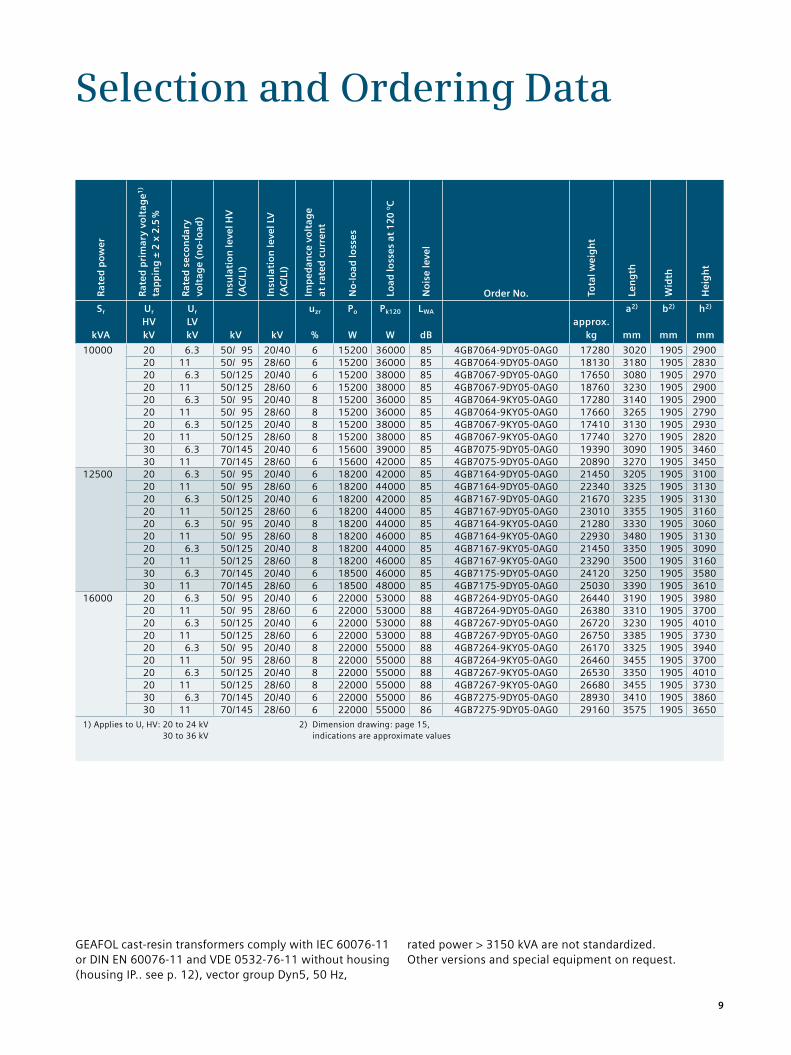
GEAFOL cast-resin transformers comply with IEC 60076-11 or DIN EN 60076-11 and VDE 0532-76-11 without housing (housing IP.. see p. 12), vector group Dyn5, 50 Hz,
rated power > 3150 kVA are not standardized. Other versions and special equipment on request.
Rat
ed p
ow
er
Rat
ed p
rim
ary
volt
age1
) ta
pp
ing
± 2
x 2
.5 %
Rat
ed s
eco
nd
ary
vo
ltag
e (n
o-l
oad
)
Insu
lati
on
leve
l HV
(A
C/L
I)
Insu
lati
on
leve
l LV
(A
C/L
I)
Imp
edan
ce v
olt
age
at
rat
ed c
urr
ent
No
-lo
ad lo
sses
Load
loss
es a
t 1
20
°C
No
ise
leve
l
Order No. Tota
l wei
gh
t
Len
gth
Wid
th
Hei
gh
t
Sr
kVA
Ur HV kV
Ur LV kV
kV
kV
uzr %
Po
W
Pk120
W
LWA
dB
approx.
kg
a2)
mm
b2)
mm
h2)
mm
10000 20 6.3 50/ 95 20/40 6 15200 36000 85 4GB7064-9DY05-0AG0 17280 3020 1905 290020 11 50/ 95 28/60 6 15200 36000 85 4GB7064-9DY05-0AG0 18130 3180 1905 283020 6.3 50/125 20/40 6 15200 38000 85 4GB7067-9DY05-0AG0 17650 3080 1905 297020 11 50/125 28/60 6 15200 38000 85 4GB7067-9DY05-0AG0 18760 3230 1905 290020 6.3 50/ 95 20/40 8 15200 36000 85 4GB7064-9KY05-0AG0 17280 3140 1905 290020 11 50/ 95 28/60 8 15200 36000 85 4GB7064-9KY05-0AG0 17660 3265 1905 279020 6.3 50/125 20/40 8 15200 38000 85 4GB7067-9KY05-0AG0 17410 3130 1905 293020 11 50/125 28/60 8 15200 38000 85 4GB7067-9KY05-0AG0 17740 3270 1905 282030 6.3 70/145 20/40 6 15600 39000 85 4GB7075-9DY05-0AG0 19390 3090 1905 346030 11 70/145 28/60 6 15600 42000 85 4GB7075-9DY05-0AG0 20890 3270 1905 3450
12500 20 6.3 50/ 95 20/40 6 18200 42000 85 4GB7164-9DY05-0AG0 21450 3205 1905 310020 11 50/ 95 28/60 6 18200 44000 85 4GB7164-9DY05-0AG0 22340 3325 1905 313020 6.3 50/125 20/40 6 18200 42000 85 4GB7167-9DY05-0AG0 21670 3235 1905 313020 11 50/125 28/60 6 18200 44000 85 4GB7167-9DY05-0AG0 23010 3355 1905 316020 6.3 50/ 95 20/40 8 18200 44000 85 4GB7164-9KY05-0AG0 21280 3330 1905 306020 11 50/ 95 28/60 8 18200 46000 85 4GB7164-9KY05-0AG0 22930 3480 1905 313020 6.3 50/125 20/40 8 18200 44000 85 4GB7167-9KY05-0AG0 21450 3350 1905 309020 11 50/125 28/60 8 18200 46000 85 4GB7167-9KY05-0AG0 23290 3500 1905 316030 6.3 70/145 20/40 6 18500 46000 85 4GB7175-9DY05-0AG0 24120 3250 1905 358030 11 70/145 28/60 6 18500 48000 85 4GB7175-9DY05-0AG0 25030 3390 1905 3610
16000 20 6.3 50/ 95 20/40 6 22000 53000 88 4GB7264-9DY05-0AG0 26440 3190 1905 398020 11 50/ 95 28/60 6 22000 53000 88 4GB7264-9DY05-0AG0 26380 3310 1905 370020 6.3 50/125 20/40 6 22000 53000 88 4GB7267-9DY05-0AG0 26720 3230 1905 401020 11 50/125 28/60 6 22000 53000 88 4GB7267-9DY05-0AG0 26750 3385 1905 373020 6.3 50/ 95 20/40 8 22000 55000 88 4GB7264-9KY05-0AG0 26170 3325 1905 394020 11 50/ 95 28/60 8 22000 55000 88 4GB7264-9KY05-0AG0 26460 3455 1905 370020 6.3 50/125 20/40 8 22000 55000 88 4GB7267-9KY05-0AG0 26530 3350 1905 401020 11 50/125 28/60 8 22000 55000 88 4GB7267-9KY05-0AG0 26680 3455 1905 373030 6.3 70/145 20/40 6 22000 55000 86 4GB7275-9DY05-0AG0 28930 3410 1905 386030 11 70/145 28/60 6 22000 55000 86 4GB7275-9DY05-0AG0 29160 3575 1905 3650
9
Connection System
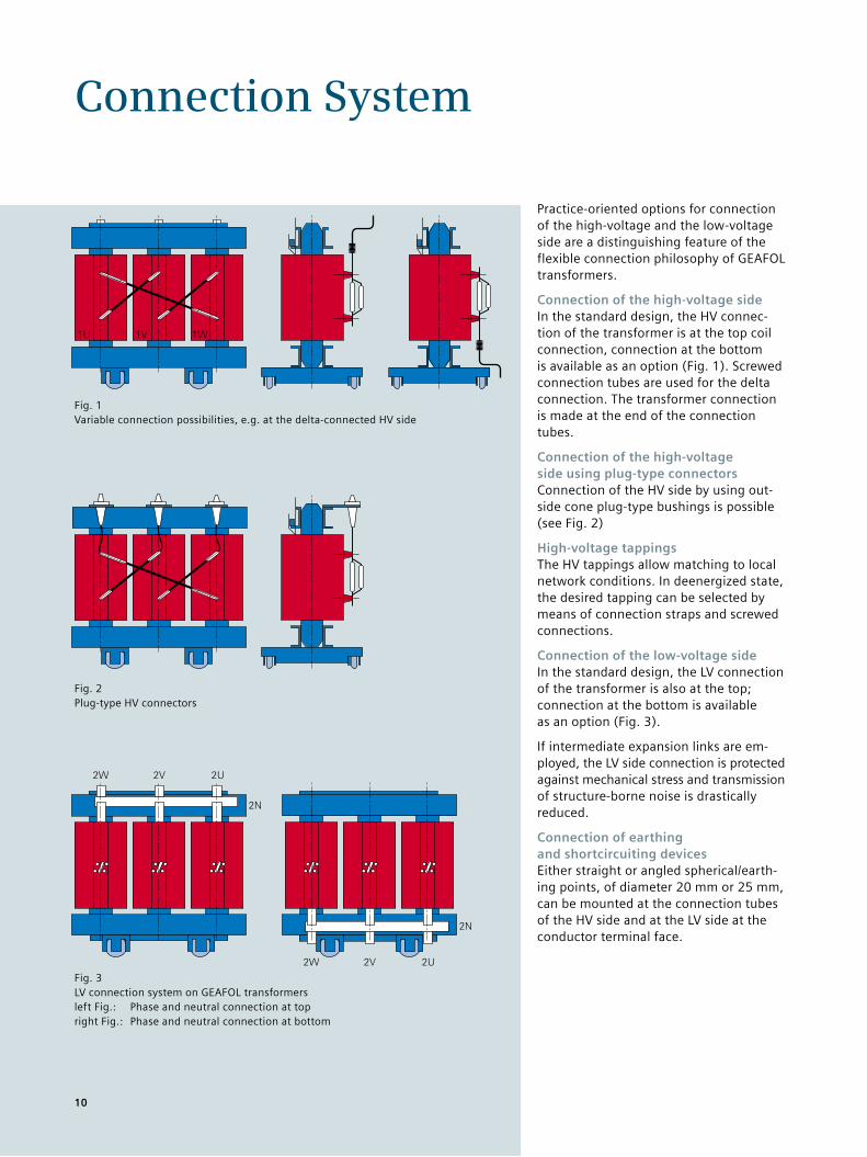
Practice-oriented options for connection of the high-voltage and the low-voltage side are a distinguishing feature of the flexible connection philosophy of GEAFOL transformers.
Connection of the high-voltage sideIn the standard design, the HV connec-tion of the transformer is at the top coil connection, connection at the bottom is available as an option (Fig. 1). Screwed connection tubes are used for the delta connection. The transformer connection is made at the end of the connection tubes.
Connection of the high-voltage side using plug-type connectors Connection of the HV side by using out-side cone plug-type bushings is possible (see Fig. 2)
High-voltage tappingsThe HV tappings allow matching to local network conditions. In deenergized state, the desired tapping can be selected by means of connection straps and screwed connections.
Connection of the low-voltage sideIn the standard design, the LV connection of the transformer is also at the top; connection at the bottom is available as an option (Fig. 3).
If intermediate expansion links are em-ployed, the LV side connection is protected against mechanical stress and transmission of structure-borne noise is drastically reduced.
Connection of earthing and shortcircuiting devicesEither straight or angled spherical/earth-ing points, of diameter 20 mm or 25 mm, can be mounted at the connection tubes of the HV side and at the LV side at the conductor terminal face.
Fig. 1 Variable connection possibilities, e.g. at the delta-connected HV side
Fig. 2 Plug-type HV connectors
Fig. 3 LV connection system on GEAFOL transformersleft Fig.: Phase and neutral connection at topright Fig.: Phase and neutral connection at bottom
10
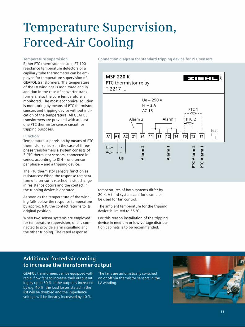
Temperature Supervision, Forced-Air CoolingTemperature supervisionEither PTC thermistor sensors, PT 100 resistance temperature detectors or a capillary tube thermometer can be em-ployed for temperature supervision of-GEAFOL transformers. The temperature of the LV windings is monitored and in addition in the case of converter trans-formers, also the core temperature is monitored. The most economical solution is monitoring by means of PTC thermistor sensors and tripping device without indi-cation of the temperature. All GEAFOL transformers are provided with at least one PTC thermistor sensor circuit for tripping purposes.
FunctionTemperature supervision by means of PTC thermistor sensors: In the case of three-phase transformers a system consists of 3 PTC thermistor sensors, connected in series, according to DIN – one sensor per phase – and a tripping device.
The PTC thermistor sensors function as resistances: When the response tempera-ture of a sensor is reached, a stepchange in resistance occurs and the contact in the tripping device is operated.
As soon as the temperature of the wind-ing falls below the response temperature by approx. 6 K, the contact returns to its original position.
When two sensor systems are employed for temperature supervision, one is con-nected to provide alarm signalling and the other tripping. The rated response
temperatures of both systems differ by 20 K. A third system can, for example, be used for fan control.
The ambient temperature for the tripping device is limited to 55 °C.
For this reason installation of the tripping device in medium or low-voltage distribu-tion cabinets is to be recommended.
Additional forced-air cooling to increase the transformer output
GEAFOL transformers can be equipped with radial-flow fans to increase their output rat-ing by up to 50 %. If the output is increased by e.g. 40 %, the load losses stated in the list will be doubled and the impedance voltage will be linearly increased by 40 %.
The fans are automatically switched on or off via thermistor sensors in the LV winding.
Connection diagram for standard tripping device for PTC sensors
MSF 220 K PTC thermistor relay T 2217 …
A1 A1 A2 21 24 11 11 12 14 T0 T2 T1
.com
Us Ala
rm 2
Ala
rm 1
PTC
Ala
rm 2
PTC
Ala
rm 1DC+
AC~- ~
Alarm 2 Alarm 1 PTC 2
PTC 1
Ue = 250 V Ie = 3 A AC 15
test
11
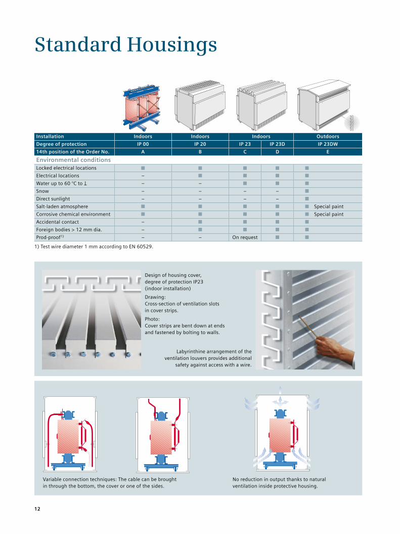
Standard Housings
Variable connection techniques: The cable can be brought in through the bottom, the cover or one of the sides.
Design of housing cover, degree of protection IP23 (indoor installation)
Drawing: Cross-section of ventilation slots in cover strips.
Photo: Cover strips are bent down at ends and fastened by bolting to walls.
Labyrinthine arrangement of the ventilation louvers provides additional
safety against access with a wire.
No reduction in output thanks to natural ventilation inside protective housing.
Installation Indoors Indoors Indoors Outdoors
Degree of protection IP 00 IP 20 IP 23 IP 23D IP 23DW
14th position of the Order No. A B C D E
Environmental conditionsLocked electrical locations ■ ■ ■ ■ ■
Electrical locations – ■ ■ ■ ■
Water up to 60 °C to l – – ■ ■ ■
Snow – – – – ■
Direct sunlight – – – – ■
Salt-laden atmosphere ■ ■ ■ ■ ■ Special paint
Corrosive chemical environment ■ ■ ■ ■ ■ Special paint
Accidental contact – ■ ■ ■ ■
Foreign bodies > 12 mm dia. – ■ ■ ■ ■
Prod-proof1) – – On request ■ ■
1) Test wire diameter 1 mm according to EN 60529.
������
����
�
12
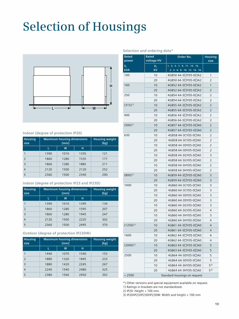
Selection of Housings
Indoor (degree of protection IP20)
Housingsize
Maximum housing dimensions [mm]
Housing weight [kg]
L W H
1 1390 1010 1335 121
2 1860 1280 1535 177
3 1860 1280 1885 211
4 2120 1500 2120 252
5 2360 1500 2340 290
Selection and ordering data*
Ratedpower
Ratedvoltage HV
Order No. Housingsize
Sr kVA
Ur kV
1. 3. 5. 7. 9. 11. 13. 15.
2. 4. 6. 8. 10. 12. 14. 16.
100 10 4GB50 44-3¨Y05-0¨A2 1
20 4GB50 64-3¨Y05-0¨A2 2
160 10 4GB52 44-3¨Y05-0¨A2 1
20 4GB52 64-3¨Y05-0¨A2 2
250 10 4GB54 44-3¨Y05-0¨A2 2
20 4GB54 64-3¨Y05-0¨A2 2
(315)1) 10 4GB55 44-3¨Y05-0¨A2 2
20 4GB55 64-3¨Y05-0¨A2 2
400 10 4GB56 44-3¨Y05-0¨A2 2
20 4GB56 64-3¨Y05-0¨A2 2
(500)1) 10 4GB57 44-3¨Y05-0¨A0 2
20 4GB57 64-3¨Y05-0¨A0 2
630 10 4GB58 44-3CY05-0¨A0 2
20 4GB58 64-3CY05-0¨A0 2
10 4GB58 44-3DY05-0¨A0 2
20 4GB58 64-3DY05-0¨A0 2
10 4GB58 44-3GY05-0¨A0 3
20 4GB58 64-3GY05-0¨A0 2
10 4GB58 44-3HY05-0¨A0 2
20 4GB58 64-3HY05-0¨A0 2
(800)1) 10 4GB59 44-3¨Y05-0¨A0 3
20 4GB59 64-3¨Y05-0¨A0 3
1000 10 4GB60 44-3CY05-0¨A0 3
20 4GB60 64-3CY05-0¨A0 3
10 4GB60 44-3DY05-0¨A0 3
20 4GB60 64-3DY05-0¨A0 3
10 4GB60 44-3GY05-0¨A0 3
20 4GB60 64-3GY05-0¨A0 4
10 4GB60 44-3HY05-0¨A0 3
20 4GB60 64-3HY05-0¨A0 4
(1250)1) 10 4GB61 44-3¨Y05-0¨A0 4
20 4GB61 64-3¨Y05-0¨A0 4
1600 10 4GB62 44-3¨Y05-0¨A0 4
20 4GB62 64-3¨Y05-0¨A0 4
(2000)1) 10 4GB63 44-3¨Y05-0¨A0 5
20 4GB63 64-3¨Y05-0¨A0 5
2500 10 4GB64 44-3DY05-0¨A0 5
20 4GB64 64-3DY05-0¨A0 5
10 4GB64 44-3HY05-0¨A0 52)
20 4GB64 64-3HY05-0¨A0 53)
> 2500 Standard housings on request
Indoor (degree of protection IP23 and IP23D)
Housingsize
Maximum housing dimensions [mm]
Housing weight [kg]
L W H
1 1390 1010 1395 134
2 1860 1280 1595 207
3 1860 1280 1945 247
4 2120 1500 2225 302
5 2360 1500 2495 370
Outdoor (degree of protection IP23DW)
Housingsize
Maximum housing dimensions [mm]
Housing weight [kg]
L W H
1 1440 1070 1540 153
2 1880 1320 1845 233
3 1880 1420 2245 267
4 2240 1540 2480 325
5 2380 1540 2950 392
*) Other versions and special equipment available on request.1) Ratings in brackets are not standardized.2) IP20: Height + 100 mm.3) IP20/IP23/IP23D/IP23DW: Width and height + 100 mm
L W
H
13
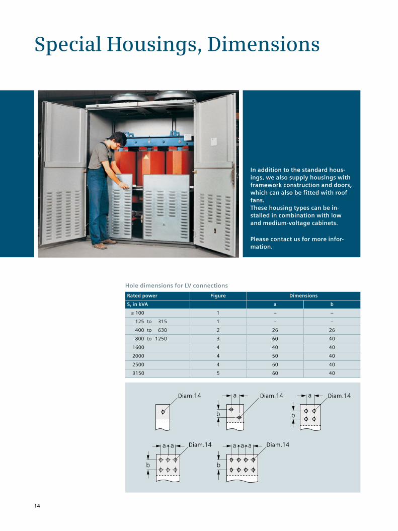
Special Housings, Dimensions
Hole dimensions for LV connections
Rated power Figure Dimensions
Sr in kVA a b
≤ 100 1 – –
125 to 315 1 – –
400 to 630 2 26 26
800 to 1250 3 60 40
1600 4 40 40
2000 4 50 40
2500 4 60 40
3150 5 60 40
In addition to the standard hous-ings, we also supply housings with framework construction and doors, which can also be fitted with roof fans. These housing types can be in-stalled in combination with low and medium-voltage cabinets.
Please contact us for more infor-mation.
14
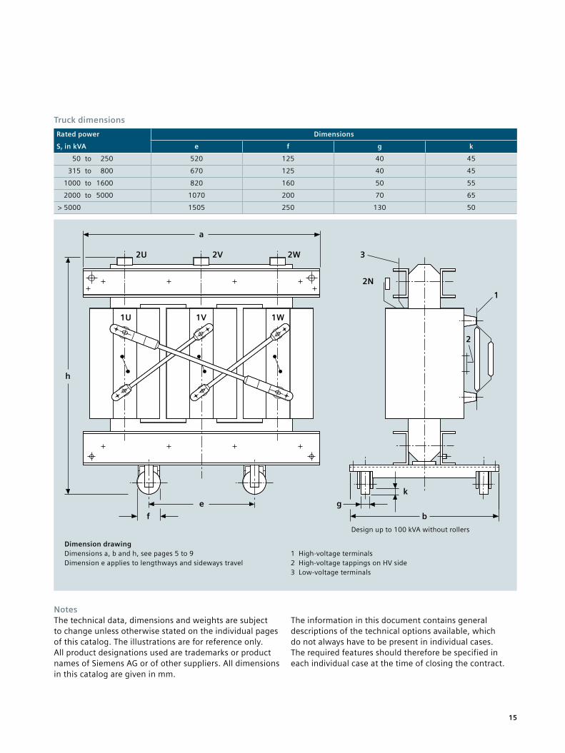
Dimension drawingDimensions a, b and h, see pages 5 to 9 Dimension e applies to lengthways and sideways travel
1 High-voltage terminals2 High-voltage tappings on HV side3 Low-voltage terminals
Truck dimensions
Rated power Dimensions
Sr in kVA e f g k
50 to 250 520 125 40 45
315 to 800 670 125 40 45
1000 to 1600 820 160 50 55
2000 to 5000 1070 200 70 65
> 5000 1505 250 130 50
NotesThe technical data, dimensions and weights are subject to change unless otherwise stated on the individual pages of this catalog. The illustrations are for reference only. All product designations used are trademarks or product names of Siemens AG or of other suppliers. All dimensions in this catalog are given in mm.
The information in this document contains general descriptions of the technical options available, which do not always have to be present in individual cases. The required features should therefore be specified in each individual case at the time of closing the contract.
15
Design up to 100 kVA without rollers
a
2U 2V 2W
1W1V1U
h
e
f
g
b
k
3
2N
1
2
Printed on elementary chlorine-free bleached paper.
All rights reserved. Trademarks mentioned in this document are the property of Siemens AG, its affiliates, or their respective owners.
Subject to change without prior notice. The information in this document contains general descriptions of the technical options available, which may not apply in all cases.The required technical options should therefore be specified in the contract.
Published by and copyright © 2013: Siemens AG Energy Sector Freyeslebenstrasse 1 91058 Erlangen, Germany
Transformatorenwerk Kirchheim/Teck Hegelstrasse 20 73230 Kirchheim/Teck, Germany Phone: +49 (0) 7021 508-0 Fax: +49 (0) 7021 508-495
Siemens Transzformátor Kft. 1214 Budapest II. Rákóczi Ferenc u.189., Hungary Phone: +36 (1) 278 5300 Fax: +36 (1) 278 5335
For more information, please contact our Customer Support Center. Phone: +49 180/524 70 00 Fax: +49 180/524 24 71 (Charges depending on provider)
E-mail: [email protected]
Power Transmission Division Order No. E50001-G640-K230-X-4A00 | Printed in Germany | Dispo 19201 | c4bs No. 7481 | TH 101-130212 | WÜ | 473320 | WS | 08132.0