Embed Size (px)
DESCRIPTION
Applied engineering in small hydropower applications seminar as presented in guyana by the GEA.
Citation preview

7/18/2019 GEA Hydro Seminar
http://slidepdf.com/reader/full/gea-hydro-seminar-569195599756d 1/160
21 st August 2015
Georgetown, Guyana
APPLIED ENGINEERING FOR
SMALL HYDROPOWER
PROJECTS
Sven HomscheidHydropower Consultant
PRACTICAL TIPS
FOR HYDROPOWER PRACTITIONERS
1
7/18/2019 GEA Hydro Seminar
http://slidepdf.com/reader/full/gea-hydro-seminar-569195599756d 2/160
! Field measurements for topographic survey of mini andsmaller hydro projects
!
Different turbine types, their technical qualities andfield of usage
!
Environmental and Social considerations of hydropowerprojects
!
Hydropower civil design options: differences,advantages and disadvantages
!
Optimizing hydropower projects: the differencebetween grid integrated and island supply
OUTLINE
2
7/18/2019 GEA Hydro Seminar
http://slidepdf.com/reader/full/gea-hydro-seminar-569195599756d 3/160
FIELD MEASUREMENTSFOR TOPOGRAPHIC
SURVEY OF MINI ANDSMALLER HYDRO
PROJECTS
3
7/18/2019 GEA Hydro Seminar
http://slidepdf.com/reader/full/gea-hydro-seminar-569195599756d 4/160
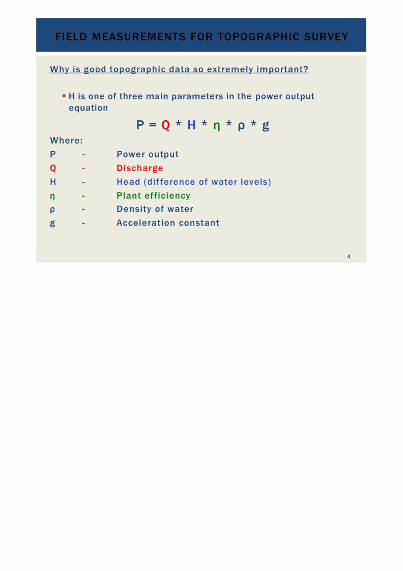
Why is good topographic data so extremely important?
! H is one of three main parameters in the power outputequation
P = Q * H * ! * " * g
Where:P - Power output
Q - Discharge
H - Head (dif ference of water levels)
! - Plant efficiency
" - Density of waterg - Acceleration constant
FIELD MEASUREMENTS FOR TOPOGRAPHIC SURVEY
4

7/18/2019 GEA Hydro Seminar
http://slidepdf.com/reader/full/gea-hydro-seminar-569195599756d 5/160
Q = flow in m3 /s
Depending on
" Geographic location
(rain forest or desert)
" Elevation above sea level
(the higher, the wetter)
" Time of the year
(rainy season or dry season)
FIELD MEASUREMENTS FOR TOPOGRAPHIC SURVEY
5

7/18/2019 GEA Hydro Seminar
http://slidepdf.com/reader/full/gea-hydro-seminar-569195599756d 6/160
Gross Head depending on" Topography - Mountain or valley
- Dam, run-off river ordiversion
Hn = net head in m
Net Head depending on" Friction losses - Pipe diameter/canal dimensions
- Pipe/canal roughness - Length of pipe/canal
" Other hydraulic losses - Trash rack - Bends - Valves
FIELD MEASUREMENTS FOR TOPOGRAPHIC SURVEY
6

7/18/2019 GEA Hydro Seminar
http://slidepdf.com/reader/full/gea-hydro-seminar-569195599756d 7/160
•
Gross Head is estimated by different means according to requiredaccuracy
• Different approaches
a)
Desktop approaches
b)
Field measurements
Some examples:
FIELD MEASUREMENTS FOR TOPOGRAPHIC SURVEY
7

7/18/2019 GEA Hydro Seminar
http://slidepdf.com/reader/full/gea-hydro-seminar-569195599756d 8/160
Desktop Approaches:Read out from Google EarthAccuracy of elevation: about 3 to 15 m depending on vegetation andrelief
FIELD MEASUREMENTS FOR TOPOGRAPHIC SURVEY
8

7/18/2019 GEA Hydro Seminar
http://slidepdf.com/reader/full/gea-hydro-seminar-569195599756d 9/160
Desktop Approaches:Read out from Google EarthAccuracy of elevation: about 3 to 15 m depending on vegetation andrelief
FIELD MEASUREMENTS FOR TOPOGRAPHIC SURVEY
9

7/18/2019 GEA Hydro Seminar
http://slidepdf.com/reader/full/gea-hydro-seminar-569195599756d 10/160
Desktop Approaches:Read out from contour lines in topographic mapsAccuracy of elevation: about one contour line interval (50 ft = 15 m)
FIELD MEASUREMENTS FOR TOPOGRAPHIC SURVEY
10

7/18/2019 GEA Hydro Seminar
http://slidepdf.com/reader/full/gea-hydro-seminar-569195599756d 11/160
Desktop Approaches:Read out from contour lines in topographic mapsAccuracy of elevation: about one contour line interval (50 ft = 15 m)
FIELD MEASUREMENTS FOR TOPOGRAPHIC SURVEY
11

7/18/2019 GEA Hydro Seminar
http://slidepdf.com/reader/full/gea-hydro-seminar-569195599756d 12/160
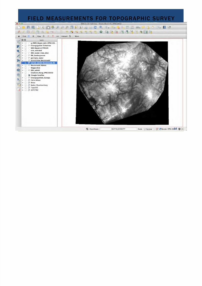
Desktop Approaches:Global Digital Elevation Models used in GIS, e.g. ASTER
•
Several products available, some free of charge, others for fees•
For example: ASTER GDEM >> https://asterweb.jpl.nasa.gov/data.asp
FIELD MEASUREMENTS FOR TOPOGRAPHIC SURVEY
12

7/18/2019 GEA Hydro Seminar
http://slidepdf.com/reader/full/gea-hydro-seminar-569195599756d 13/160
FIELD MEASUREMENTS FOR TOPOGRAPHIC SURVEY
13
7/18/2019 GEA Hydro Seminar
http://slidepdf.com/reader/full/gea-hydro-seminar-569195599756d 14/160
FIELD MEASUREMENTS FOR TOPOGRAPHIC SURVEY
14

7/18/2019 GEA Hydro Seminar
http://slidepdf.com/reader/full/gea-hydro-seminar-569195599756d 15/160
FIELD MEASUREMENTS FOR TOPOGRAPHIC SURVEY
15

7/18/2019 GEA Hydro Seminar
http://slidepdf.com/reader/full/gea-hydro-seminar-569195599756d 16/160
FIELD MEASUREMENTS FOR TOPOGRAPHIC SURVEY
16

7/18/2019 GEA Hydro Seminar
http://slidepdf.com/reader/full/gea-hydro-seminar-569195599756d 17/160
Desktop Approaches:Global Digital Elevation Models used in GIS, e.g. ASTER
•
Several products available, some free of charge, others for fee•
For example: ASTER GDEM >> https://asterweb.jpl.nasa.gov/data.asp•
Spatial Resolution: 30 x 30 m•
Vertical Accuracy: RMS Error = 8.68 m, depending on relief structure
FIELD MEASUREMENTS FOR TOPOGRAPHIC SURVEY
17

7/18/2019 GEA Hydro Seminar
http://slidepdf.com/reader/full/gea-hydro-seminar-569195599756d 18/160
Conclusion to Desktop Approaches:
(-) Vertical accuracy is quite poor(+) Data is quickly available for almost all corners of the world(+) Some data is available for free; more precise data costs money(+) Usefulness of the desktop approach for
• initial analysis of sites and site identification
•
initial analysis of high head projects where the relative error issmall compared to the overall head
(-) Method is not suitable for• analysis of low head sites where every half meter head counts•
detailed analysis of any projects(+) The desktop approach gives a quick overview on the site
(+) Allows identification of geomorthologic basics such as mountainfolding, faults etc.
FIELD MEASUREMENTS FOR TOPOGRAPHIC SURVEY
18

7/18/2019 GEA Hydro Seminar
http://slidepdf.com/reader/full/gea-hydro-seminar-569195599756d 19/160
Field Measurement Approaches:Hand held GPS
(+) Easy to handle(+) Quick results(-) Poor accuracy for elevations (<5 m at best)(+) Spatial accuracy: up to 1 m
(-) Not applicable in deep forest
FIELD MEASUREMENTS FOR TOPOGRAPHIC SURVEY
19

7/18/2019 GEA Hydro Seminar
http://slidepdf.com/reader/full/gea-hydro-seminar-569195599756d 20/160
Field Measurement Approaches:Water level bubble, line and measuring tape
FIELD MEASUREMENTS FOR TOPOGRAPHIC SURVEY
20

7/18/2019 GEA Hydro Seminar
http://slidepdf.com/reader/full/gea-hydro-seminar-569195599756d 21/160
Field Measurement Approaches:Water level bubble, line and measuring tape
(+) Very cheap tools available in hardware store(+) Relatively quick for small sites, time consuming for larger sites(-) Accuracy depends on users’ skills; generally around 1 – 2 m per
100 m longitudinal distance
(-) Accuracy of bubble reading needs thorough practice(+) Best when supplemented with aerial photos, e.g. Google Earth(+) Applicable nearly everywhere
FIELD MEASUREMENTS FOR TOPOGRAPHIC SURVEY
21

7/18/2019 GEA Hydro Seminar
http://slidepdf.com/reader/full/gea-hydro-seminar-569195599756d 22/160
Field Measurement Approaches:Hose water level and measuring tape
FIELD MEASUREMENTS FOR TOPOGRAPHIC SURVEY
22

7/18/2019 GEA Hydro Seminar
http://slidepdf.com/reader/full/gea-hydro-seminar-569195599756d 23/160
Field Measurement Approaches:Hose water level and measuring tape
FIELD MEASUREMENTS FOR TOPOGRAPHIC SURVEY
23

7/18/2019 GEA Hydro Seminar
http://slidepdf.com/reader/full/gea-hydro-seminar-569195599756d 24/160
Field Measurement Approaches:Hose water level and measuring tape
FIELD MEASUREMENTS FOR TOPOGRAPHIC SURVEY
24

7/18/2019 GEA Hydro Seminar
http://slidepdf.com/reader/full/gea-hydro-seminar-569195599756d 25/160
Field Measurement Approaches:Hose water level and measuring tape
(+) Cheap tools(+) Relatively quick for small and shallow sites, time consuming for larger
and steep sites; can only measure as far as the hose is long(-) Accuracy depends on users’ skills; generally around 0.3 – 1 m per
100 m(+) Best when supplemented with aerial photos, e.g. Google Earth(+) Applicable nearly everywhere
FIELD MEASUREMENTS FOR TOPOGRAPHIC SURVEY
25

7/18/2019 GEA Hydro Seminar
http://slidepdf.com/reader/full/gea-hydro-seminar-569195599756d 26/160
Field Measurement Approaches:Levelling machine and measuring tape
FIELD MEASUREMENTS FOR TOPOGRAPHIC SURVEY
26

7/18/2019 GEA Hydro Seminar
http://slidepdf.com/reader/full/gea-hydro-seminar-569195599756d 27/160
Field Measurement Approaches:Levelling machine and measuring tape
(+) Simple technology, needs only brief introduction(+) Relatively cheap equipment (Levelling machine: 200 USD; Tripod: 100
USD; Scale bar: 80 USD)(+) Accurate results of up to 0.001 m
(-) Relatively time consuming(+) Can measure far distances in shallow areas(-) Needs at least a team of two persons
FIELD MEASUREMENTS FOR TOPOGRAPHIC SURVEY
27

7/18/2019 GEA Hydro Seminar
http://slidepdf.com/reader/full/gea-hydro-seminar-569195599756d 28/160
Field Measurement Approaches:Tachymeter
FIELD MEASUREMENTS FOR TOPOGRAPHIC SURVEY
28
7/18/2019 GEA Hydro Seminar
http://slidepdf.com/reader/full/gea-hydro-seminar-569195599756d 29/160
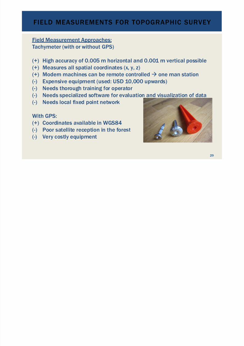
Field Measurement Approaches:Tachymeter (with or without GPS)
(+) High accuracy of 0.005 m horizontal and 0.001 m vertical possible(+) Measures all spatial coordinates (x, y, z)(+) Modern machines can be remote controlled" one man station(-) Expensive equipment (used: USD 10,000 upwards)
(-) Needs thorough training for operator(-) Needs specialized software for evaluation and visualization of data(-) Needs local fixed point network
With GPS:(+) Coordinates available in WGS84
(-) Poor satellite reception in the forest(-) Very costly equipment
FIELD MEASUREMENTS FOR TOPOGRAPHIC SURVEY
29

7/18/2019 GEA Hydro Seminar
http://slidepdf.com/reader/full/gea-hydro-seminar-569195599756d 30/160
Field Measurement Approaches:Survey Drone (= Unmanned Aerial Vehicle)
FIELD MEASUREMENTS FOR TOPOGRAPHIC SURVEY
30
Multirotor G4 Surveying Robot
e-bee of Sensefly

7/18/2019 GEA Hydro Seminar
http://slidepdf.com/reader/full/gea-hydro-seminar-569195599756d 31/160
Field Measurement Approaches:Survey Drone (= Unmanned Aerial Vehicle)
How it works:•
Remote controlled drone carries multiple sensors•
GPS/DGPS•
Photo camera resolution > 16 Mpix
•
Ground proximity•
Temperature•
Altitude• Wind velocity and direction
• Flying altitude: about 200 m
•
Photos and other data are stored on the device’s memory when flying
over the investigation area, or are transmitted real-time to a laptop onthe ground
• The data is superposed and from each two neighboring photos a
digital elevation model is produced by ortho-photogrammetry
FIELD MEASUREMENTS FOR TOPOGRAPHIC SURVEY
31

7/18/2019 GEA Hydro Seminar
http://slidepdf.com/reader/full/gea-hydro-seminar-569195599756d 32/160
Field Measurement Approaches:Survey Drone (= Unmanned Aerial Vehicle)
How it works: (continued)•
The data is evaluated with specialized software•
Terrestrially measured reference points arerequired to improve the precision
•
High density point clouds are generated from themeasured data
• One pixel is up to 1.5 cm on the ground
• Accuracy: up to 0.001 m, normally 0.03 to 0.05 m•
Was successfully applied in Ethiopia’s GrandRenaissance hydropower project
FIELD MEASUREMENTS FOR TOPOGRAPHIC SURVEY
32

7/18/2019 GEA Hydro Seminar
http://slidepdf.com/reader/full/gea-hydro-seminar-569195599756d 33/160
Field Measurement Approaches:Survey Drone (= Unmanned Aerial Vehicle)
(+) Fast field work over large areas(+) Produces ortho-photos, contour maps, digital elevation models and
other information depending on the deployed sensors(+) Various models are available and have been tested in practice
(-) Requires high-tech software for data evaluation(+) Accuracy: 0.01 m horizontal; 0.05 m vertical (if reference points avail)(-) Very expensive equipment (> USD 25,000) and software (>
USD 3,500)(-) Needs highly specialized skills(-) Not everywhere applicable without aviation license
(+) Future technology with lots of potential
FIELD MEASUREMENTS FOR TOPOGRAPHIC SURVEY
33

7/18/2019 GEA Hydro Seminar
http://slidepdf.com/reader/full/gea-hydro-seminar-569195599756d 34/160
DIFFERENT TURBINE
TYPES, THEIRTECHNICAL QUALITIESAND FIELD OF USAGE
34
7/18/2019 GEA Hydro Seminar
http://slidepdf.com/reader/full/gea-hydro-seminar-569195599756d 35/160
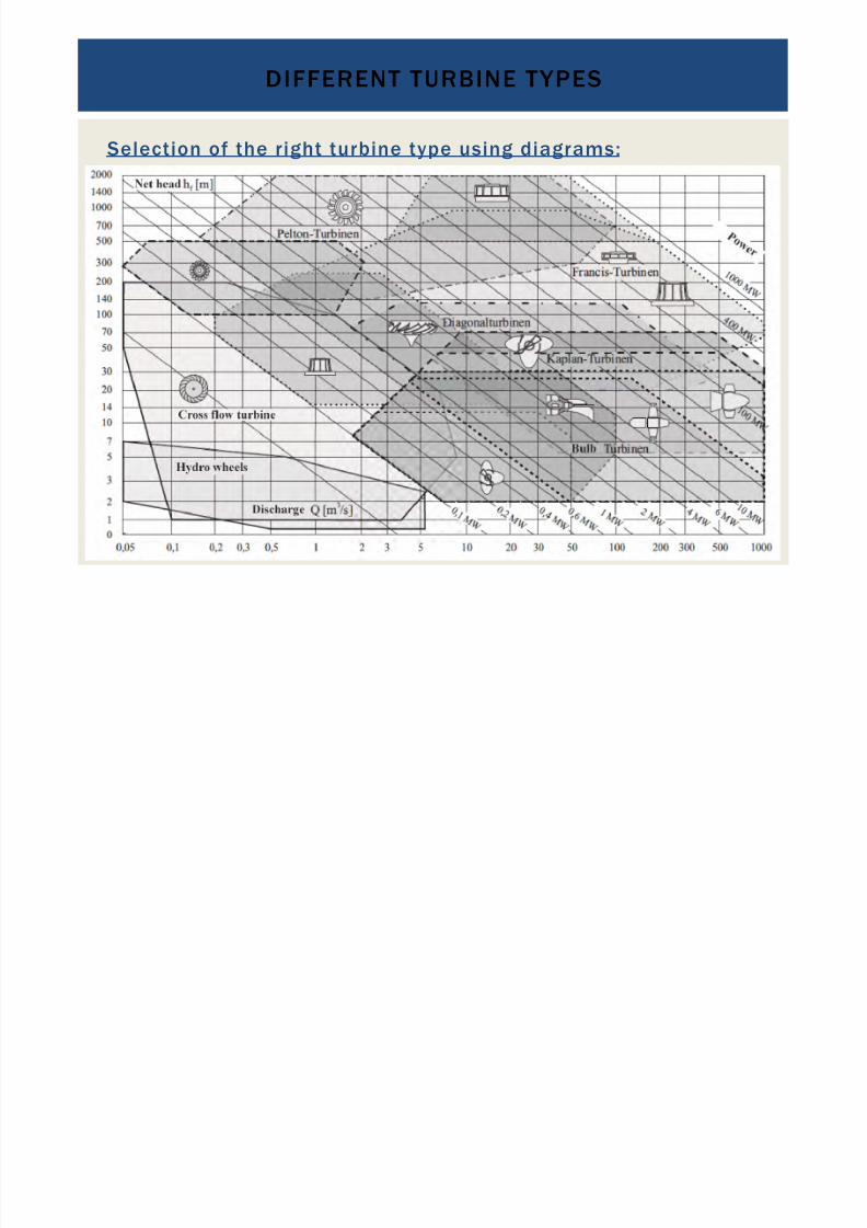
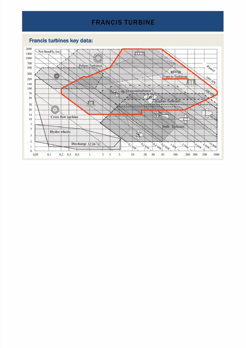
Selection of the right turbine type using diagrams:
DIFFERENT TURBINE TYPES
35
7/18/2019 GEA Hydro Seminar
http://slidepdf.com/reader/full/gea-hydro-seminar-569195599756d 36/160
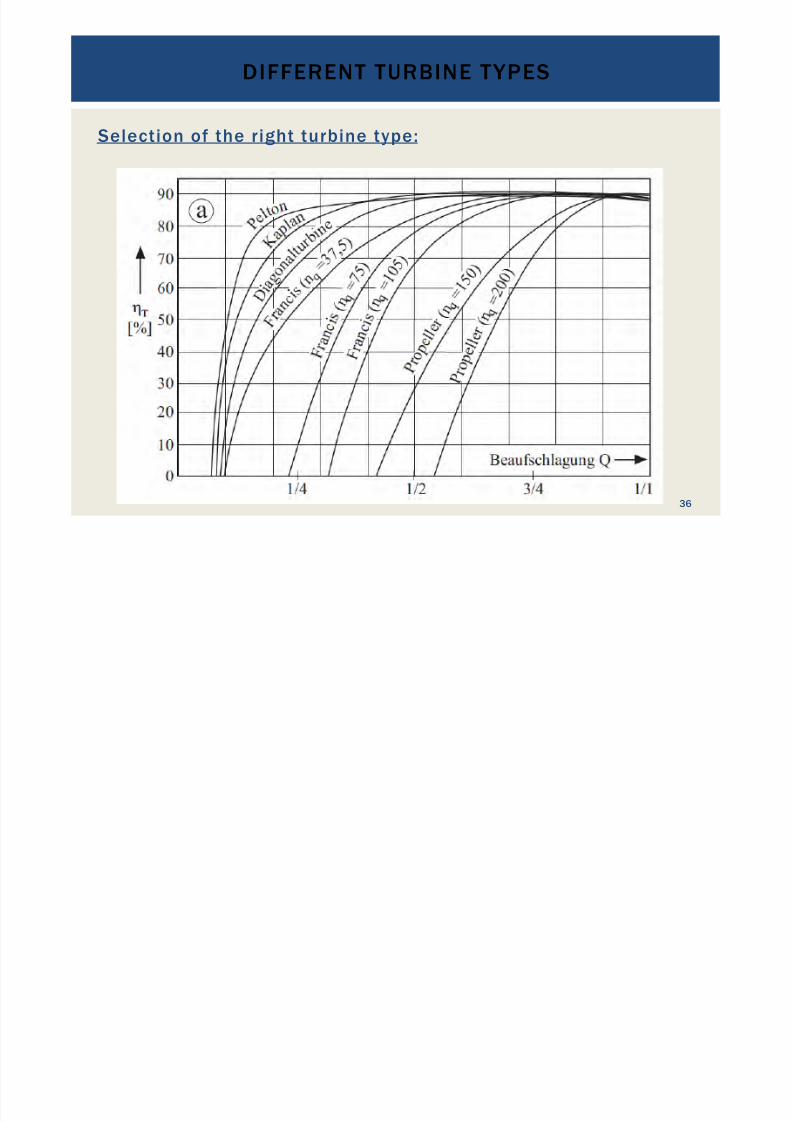
Selection of the right turbine type:
DIFFERENT TURBINE TYPES
36

7/18/2019 GEA Hydro Seminar
http://slidepdf.com/reader/full/gea-hydro-seminar-569195599756d 37/160
Pelton turbine: Impulse turbine
PELTON TURBINE
37

7/18/2019 GEA Hydro Seminar
http://slidepdf.com/reader/full/gea-hydro-seminar-569195599756d 38/160
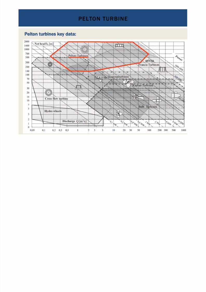
Pelton turbines key data:
•
Impulse turbine for high heads
PELTON TURBINE
38
7/18/2019 GEA Hydro Seminar
http://slidepdf.com/reader/full/gea-hydro-seminar-569195599756d 39/160
Pelton turbines key data:
•
Impulse turbine for high heads
PELTON TURBINE
39
7/18/2019 GEA Hydro Seminar
http://slidepdf.com/reader/full/gea-hydro-seminar-569195599756d 40/160
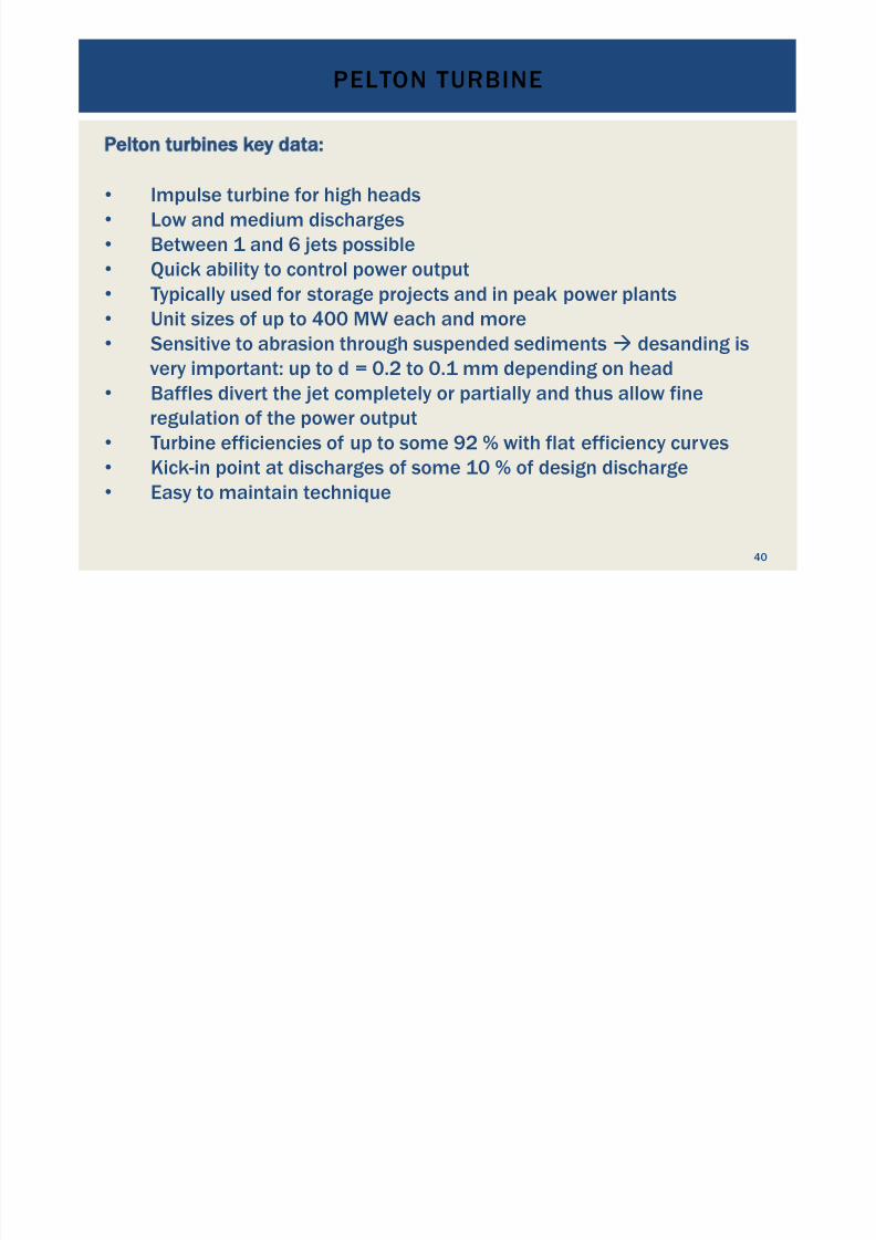
Pelton turbines key data:
•
Impulse turbine for high heads•
Low and medium discharges•
Between 1 and 6 jets possible•
Quick ability to control power output•
Typically used for storage projects and in peak power plants
•
Unit sizes of up to 400 MW each and more•
Sensitive to abrasion through suspended sediments " desanding isvery important: up to d = 0.2 to 0.1 mm depending on head
• Baffles divert the jet completely or partially and thus allow fine
regulation of the power output•
Turbine efficiencies of up to some 92 % with flat efficiency curves
•
Kick-in point at discharges of some 10 % of design discharge•
Easy to maintain technique
PELTON TURBINE
40
7/18/2019 GEA Hydro Seminar
http://slidepdf.com/reader/full/gea-hydro-seminar-569195599756d 41/160
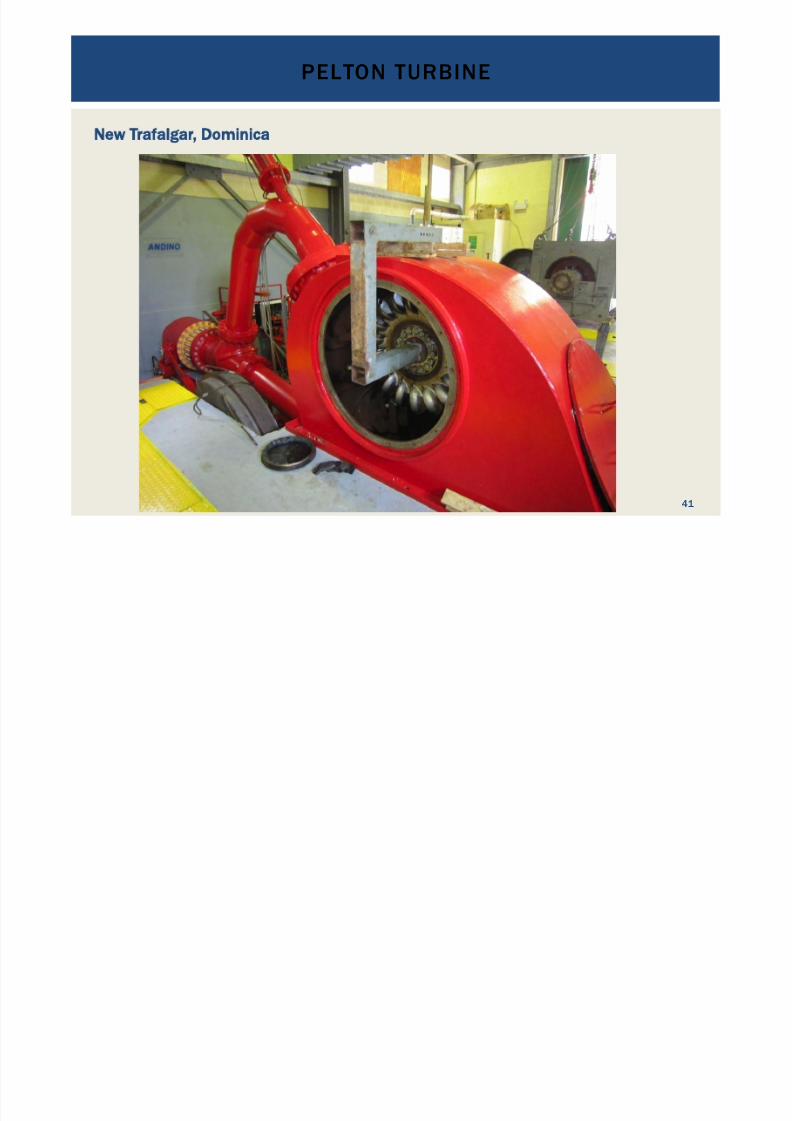
New Trafalgar, Dominica
PELTON TURBINE
41

7/18/2019 GEA Hydro Seminar
http://slidepdf.com/reader/full/gea-hydro-seminar-569195599756d 42/160
Needle valve and baffle
PELTON TURBINE
42

7/18/2019 GEA Hydro Seminar
http://slidepdf.com/reader/full/gea-hydro-seminar-569195599756d 43/160
Pelton blades: cups
PELTON TURBINE
43
7/18/2019 GEA Hydro Seminar
http://slidepdf.com/reader/full/gea-hydro-seminar-569195599756d 44/160
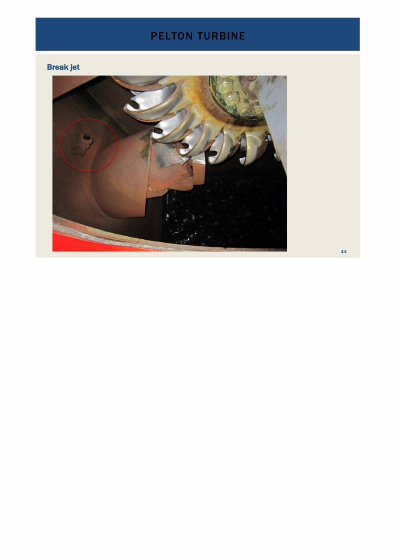
Break jet
PELTON TURBINE
44

7/18/2019 GEA Hydro Seminar
http://slidepdf.com/reader/full/gea-hydro-seminar-569195599756d 45/160
Turgo turbine: Impulse turbine
TURGO TURBINE
45

7/18/2019 GEA Hydro Seminar
http://slidepdf.com/reader/full/gea-hydro-seminar-569195599756d 46/160
Difference between Turgo and Pelton turbines
TURGO TURBINE
46
The Turgo turbine can process about twice the amount of water than Pelton turbines
7/18/2019 GEA Hydro Seminar
http://slidepdf.com/reader/full/gea-hydro-seminar-569195599756d 47/160
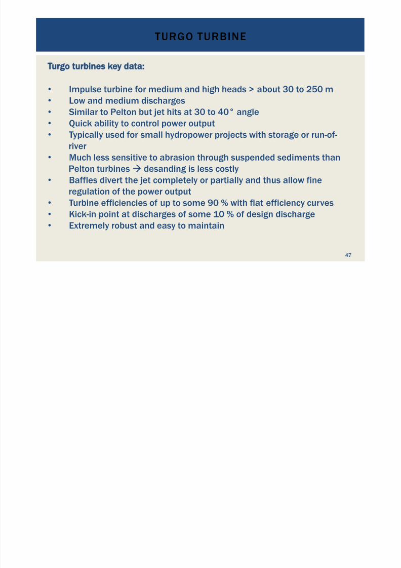
Turgo turbines key data:
•
Impulse turbine for medium and high heads > about 30 to 250 m•
Low and medium discharges•
Similar to Pelton but jet hits at 30 to 40° angle•
Quick ability to control power output•
Typically used for small hydropower projects with storage or run-of-
river•
Much less sensitive to abrasion through suspended sediments thanPelton turbines " desanding is less costly
• Baffles divert the jet completely or partially and thus allow fine
regulation of the power output•
Turbine efficiencies of up to some 90 % with flat efficiency curves
•
Kick-in point at discharges of some 10 % of design discharge•
Extremely robust and easy to maintain
TURGO TURBINE
47
7/18/2019 GEA Hydro Seminar
http://slidepdf.com/reader/full/gea-hydro-seminar-569195599756d 48/160
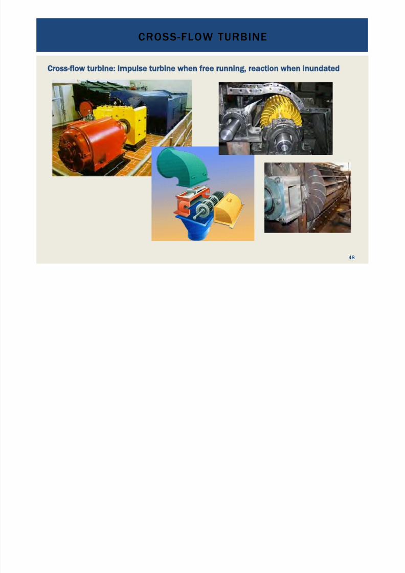
Cross-flow turbine: Impulse turbine when free running, reaction when inundated
CROSS-FLOW TURBINE
48
7/18/2019 GEA Hydro Seminar
http://slidepdf.com/reader/full/gea-hydro-seminar-569195599756d 49/160
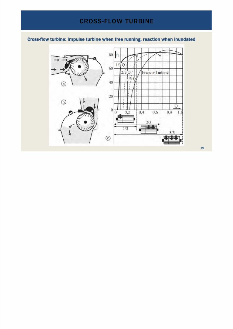
Cross-flow turbine: Impulse turbine when free running, reaction when inundated
CROSS-FLOW TURBINE
49

7/18/2019 GEA Hydro Seminar
http://slidepdf.com/reader/full/gea-hydro-seminar-569195599756d 50/160
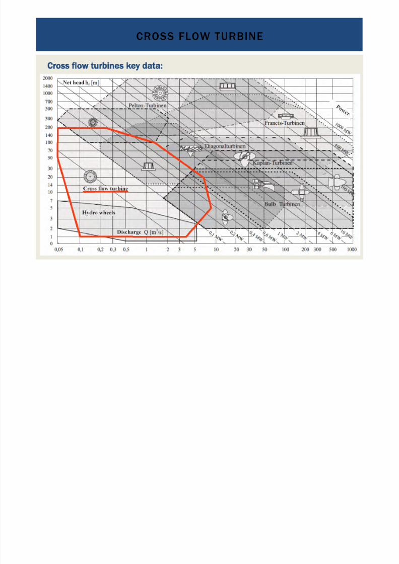
Cross flow turbines key data:
•
Impulse or reaction turbine depending on operation mode•
Low and medium heads > about 1 to 200 m•
Low discharges: 0.025 to 13 m3 /s
CROSS FLOW TURBINE
50
7/18/2019 GEA Hydro Seminar
http://slidepdf.com/reader/full/gea-hydro-seminar-569195599756d 51/160
Cross flow turbines key data:
•
Impulse or reaction turbine depending on operation mode•
Low and medium heads > about 1 to 200 m•
Low discharges
CROSS FLOW TURBINE
51
7/18/2019 GEA Hydro Seminar
http://slidepdf.com/reader/full/gea-hydro-seminar-569195599756d 52/160
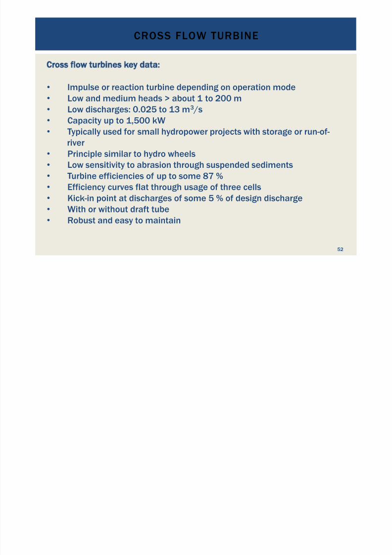
Cross flow turbines key data:
•
Impulse or reaction turbine depending on operation mode•
Low and medium heads > about 1 to 200 m•
Low discharges: 0.025 to 13 m3 /s•
Capacity up to 1,500 kW•
Typically used for small hydropower projects with storage or run-of-
river•
Principle similar to hydro wheels•
Low sensitivity to abrasion through suspended sediments•
Turbine efficiencies of up to some 87 %•
Efficiency curves flat through usage of three cells•
Kick-in point at discharges of some 5 % of design discharge
•
With or without draft tube•
Robust and easy to maintain
CROSS FLOW TURBINE
52

7/18/2019 GEA Hydro Seminar
http://slidepdf.com/reader/full/gea-hydro-seminar-569195599756d 53/160
Francis turbine: Reaction turbine
FRANCIS TURBINE
53

7/18/2019 GEA Hydro Seminar
http://slidepdf.com/reader/full/gea-hydro-seminar-569195599756d 54/160
Francis turbines key data:
•
Reaction turbine•
Medium and high heads from about 14 to 2,000 m•
Medium and high discharges: 0.2 to 1,000 m3 /s•
Capacity up to 750 kW
FRANCIS TURBINE
54
7/18/2019 GEA Hydro Seminar
http://slidepdf.com/reader/full/gea-hydro-seminar-569195599756d 55/160
Francis turbines key data:
•
Reaction turbine•
Medium and high heads > about 14 to 2,000 m•
Medium and high discharges: 0.2 to 1,000 m3 /s•
Capacity up to 750 kW
FRANCIS TURBINE
55
7/18/2019 GEA Hydro Seminar
http://slidepdf.com/reader/full/gea-hydro-seminar-569195599756d 56/160
Francis turbines key data:
•
Reaction turbine•
Medium and high heads > about 14 to 2,000 m•
Medium and high discharges: 0.2 to 1,000 m3 /s•
Capacity up to 750 kW per unit•
Typically used for small, medium and large hydropower projects
with storage or run-of-river, and as pump-turbines•
Low sensitivity to abrasion through suspended sediments•
Turbine efficiencies of up to some 94 %•
Efficiency curves rather pointy•
Kick-in point at discharges of some 30 % of design discharge•
With or without draft tube
•
With or without spiral case•
Moderate to maintain
FRANCIS TURBINE
56
7/18/2019 GEA Hydro Seminar
http://slidepdf.com/reader/full/gea-hydro-seminar-569195599756d 57/160
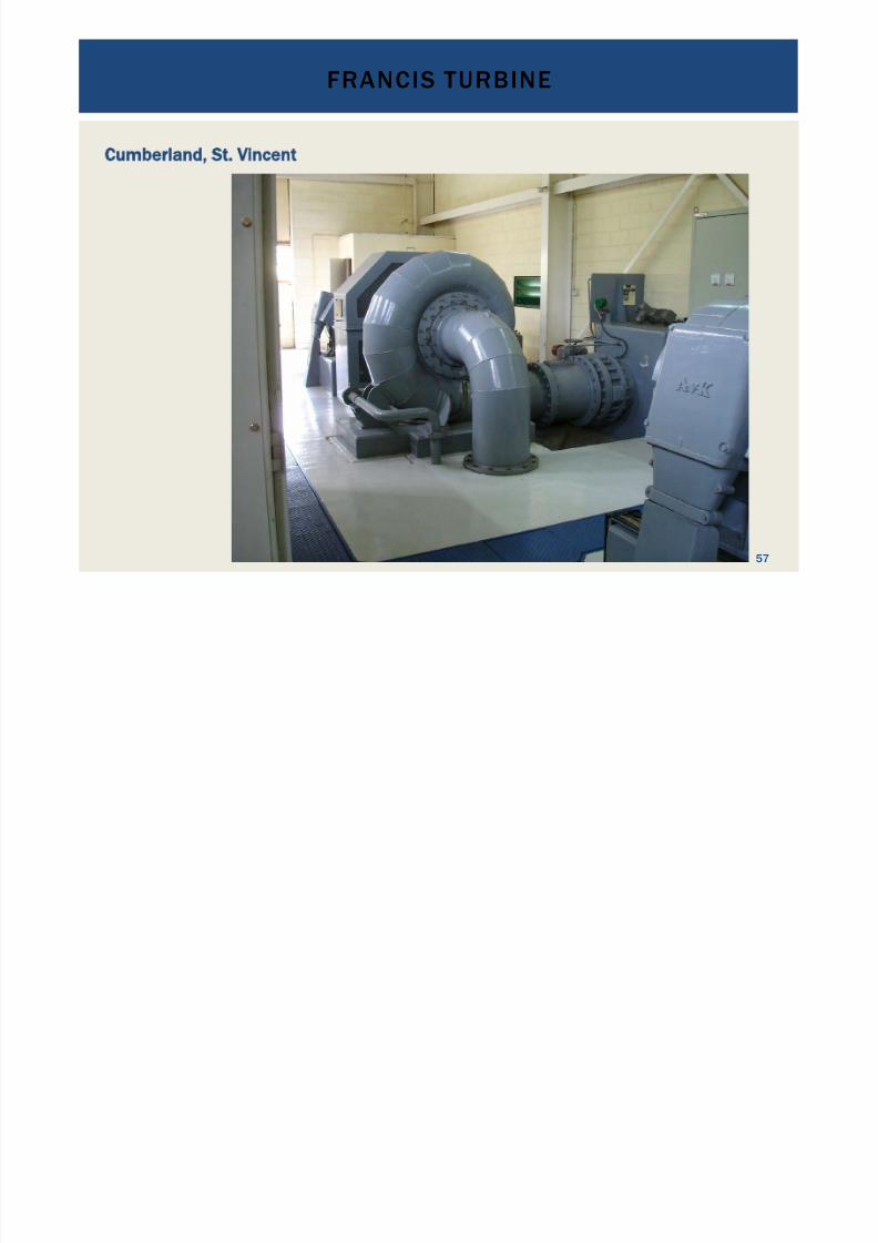
Cumberland, St. Vincent
FRANCIS TURBINE
57
7/18/2019 GEA Hydro Seminar
http://slidepdf.com/reader/full/gea-hydro-seminar-569195599756d 58/160
FRANCIS TURBINE
58
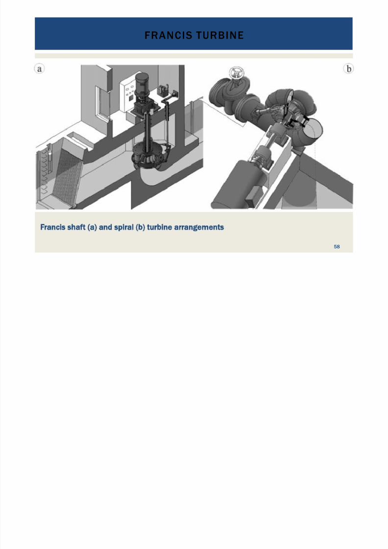
Francis shaft (a) and spiral (b) turbine arrangements
7/18/2019 GEA Hydro Seminar
http://slidepdf.com/reader/full/gea-hydro-seminar-569195599756d 59/160
FRANCIS TURBINE
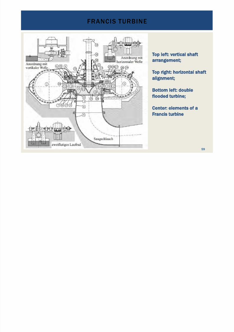
59
Top left: vertical shaft
arrangement;
Top right: horizontal shaft
alignment;
Bottom left: double
flooded turbine;
Center: elements of a
Francis turbine
7/18/2019 GEA Hydro Seminar
http://slidepdf.com/reader/full/gea-hydro-seminar-569195599756d 60/160
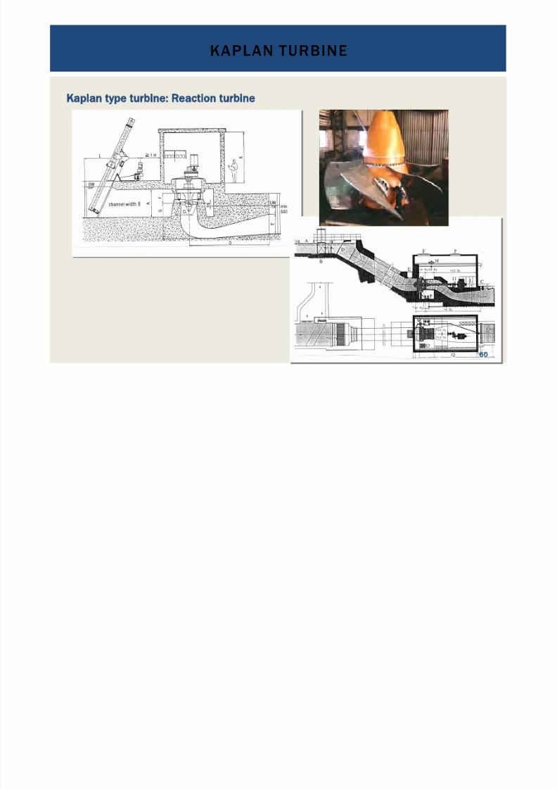
Kaplan type turbine: Reaction turbine
KAPLAN TURBINE
60

7/18/2019 GEA Hydro Seminar
http://slidepdf.com/reader/full/gea-hydro-seminar-569195599756d 61/160
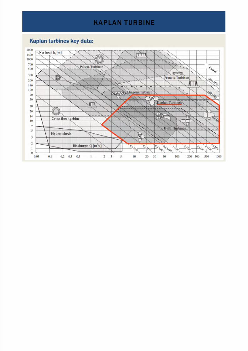
Kaplan turbines key data:
•
Reaction turbine•
Low and medium heads < about 80 m•
Medium and high discharges: 1.5 to 1,000 m3 /s•
Capacity up to 350 kW per unit
KAPLAN TURBINE
61
7/18/2019 GEA Hydro Seminar
http://slidepdf.com/reader/full/gea-hydro-seminar-569195599756d 62/160
Kaplan turbines key data:
•
Reaction turbine•
Low and medium heads < about 80 m•
Medium and high discharges: 1.5 to 1,000 m3 /s•
Capacity up to 350 kW per unit
KAPLAN TURBINE
62
7/18/2019 GEA Hydro Seminar
http://slidepdf.com/reader/full/gea-hydro-seminar-569195599756d 63/160
Kaplan turbines key data:
•
Reaction turbine•
Low and medium heads < about 80 m•
Medium and high discharges: 1.5 to 1,000 m3 /s•
Capacity up to 350 kW per unit•
Typically used for small and medium hydropower projects with
small storage or run-of-river•
Low sensitivity to abrasion through suspended sediments•
Turbine efficiencies of up to some 95 %•
Efficiency curves flat through double regulated blades/guide vanes•
Kick-in point at discharges of some 20 % of design discharge•
With or without draft tube
•
With or without spiral case•
High maintenance
KAPLAN TURBINE
63
7/18/2019 GEA Hydro Seminar
http://slidepdf.com/reader/full/gea-hydro-seminar-569195599756d 64/160
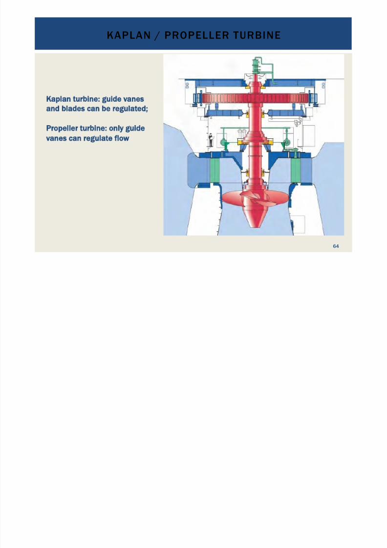
Kaplan turbine: guide vanes
and blades can be regulated;
Propeller turbine: only guide
vanes can regulate flow
KAPLAN / PROPELLER TURBINE
64
7/18/2019 GEA Hydro Seminar
http://slidepdf.com/reader/full/gea-hydro-seminar-569195599756d 65/160
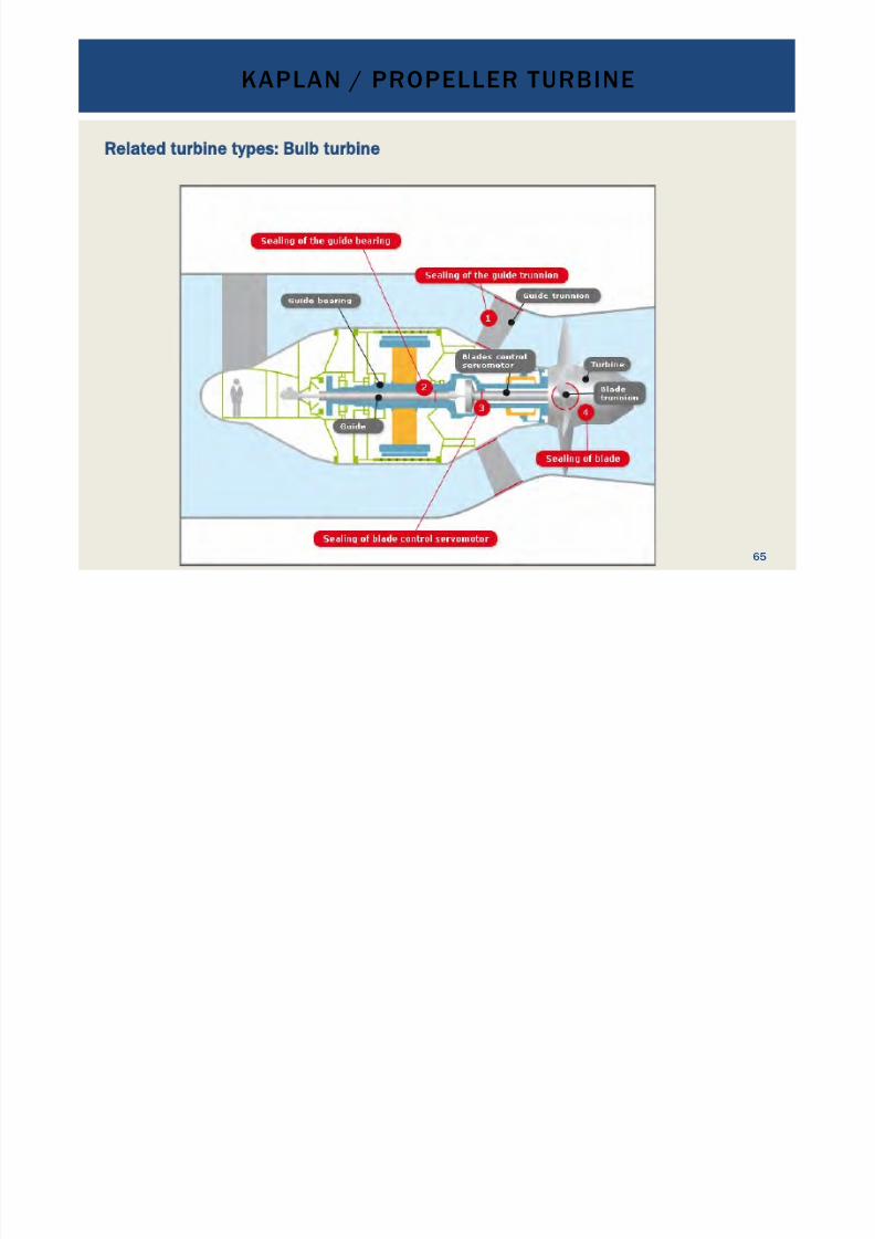
Related turbine types: Bulb turbine
KAPLAN / PROPELLER TURBINE
65
7/18/2019 GEA Hydro Seminar
http://slidepdf.com/reader/full/gea-hydro-seminar-569195599756d 66/160
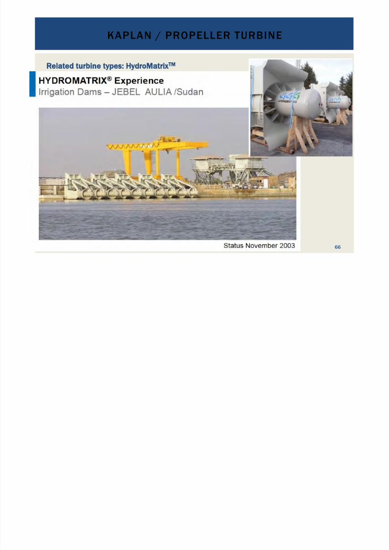
Related turbine types: HydroMatrix
TM
KAPLAN / PROPELLER TURBINE
66
7/18/2019 GEA Hydro Seminar
http://slidepdf.com/reader/full/gea-hydro-seminar-569195599756d 67/160
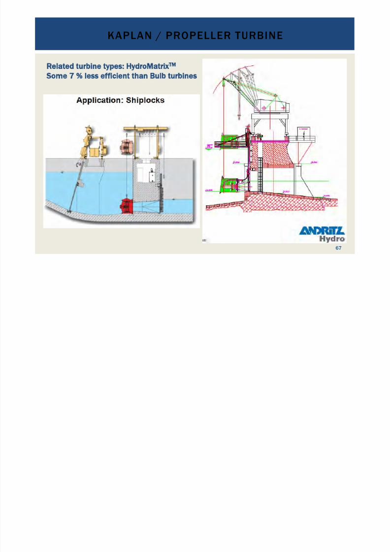
Related turbine types: HydroMatrix
TM
Some 7 less efficient than Bulb turbines
KAPLAN / PROPELLER TURBINE
67
7/18/2019 GEA Hydro Seminar
http://slidepdf.com/reader/full/gea-hydro-seminar-569195599756d 68/160
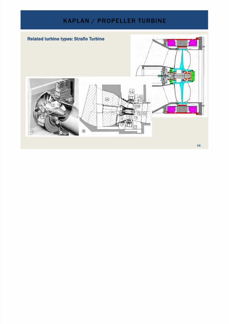
Related turbine types: Straflo Turbine
KAPLAN / PROPELLER TURBINE
68
7/18/2019 GEA Hydro Seminar
http://slidepdf.com/reader/full/gea-hydro-seminar-569195599756d 69/160
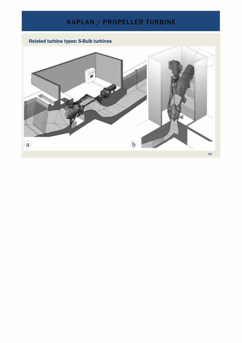
Related turbine types: S-Bulb turbines
KAPLAN / PROPELLER TURBINE
69
7/18/2019 GEA Hydro Seminar
http://slidepdf.com/reader/full/gea-hydro-seminar-569195599756d 70/160
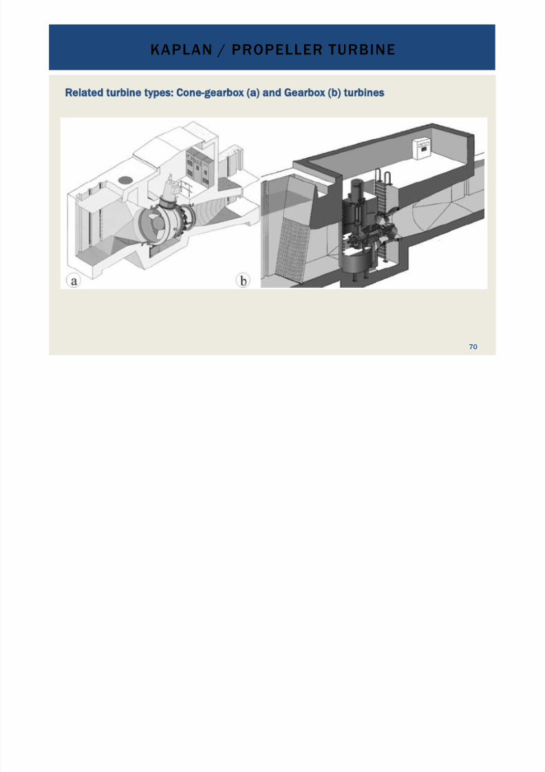
Related turbine types: Cone-gearbox (a) and Gearbox (b) turbines
KAPLAN / PROPELLER TURBINE
70

7/18/2019 GEA Hydro Seminar
http://slidepdf.com/reader/full/gea-hydro-seminar-569195599756d 71/160
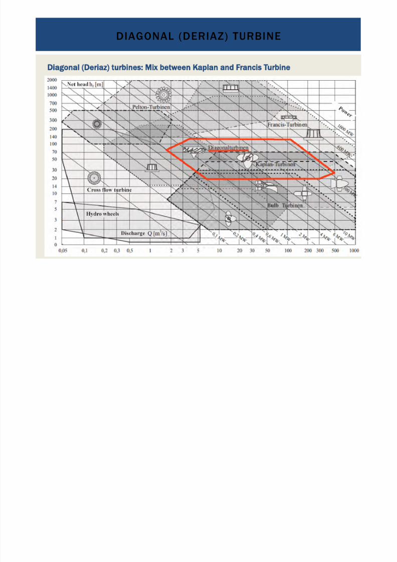
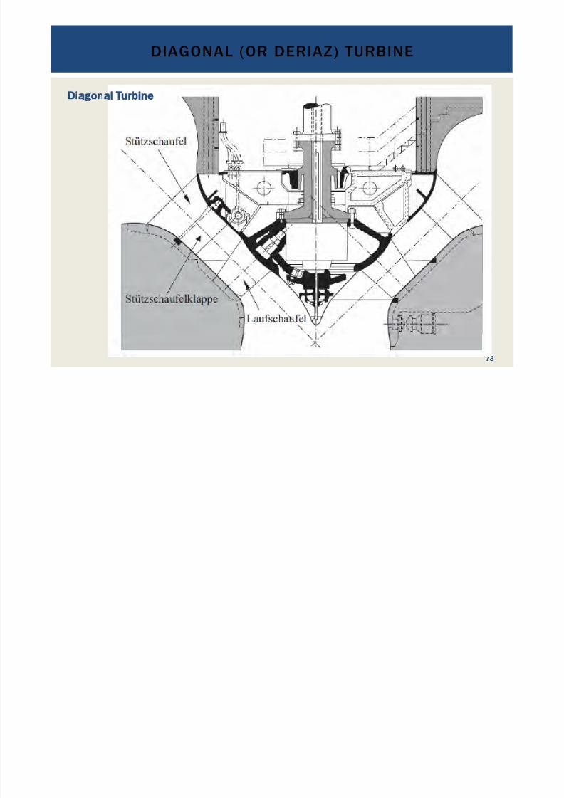
Diagonal (Deriaz) turbines: Mix between Kaplan and Francis Turbine
• Reaction turbine
•
Shape similar to Francis Turbines•
Double regulated: guide vanes and blades are adjustable•
Medium heads 20 to about 140 m•
Medium and high discharges: 1.8 to 500 m3 /s
•
Capacity up to 100 MW per unit
DIAGONAL (OR DERIAZ) TURBINE
71
7/18/2019 GEA Hydro Seminar
http://slidepdf.com/reader/full/gea-hydro-seminar-569195599756d 72/160
Diagonal (Deriaz) turbines: Mix between Kaplan and Francis Turbine
DIAGONAL (DERIAZ) TURBINE
72
7/18/2019 GEA Hydro Seminar
http://slidepdf.com/reader/full/gea-hydro-seminar-569195599756d 73/160
DIAGONAL (OR DERIAZ) TURBINE
73
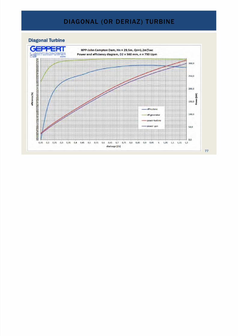
Diagonal Turbine
7/18/2019 GEA Hydro Seminar
http://slidepdf.com/reader/full/gea-hydro-seminar-569195599756d 74/160
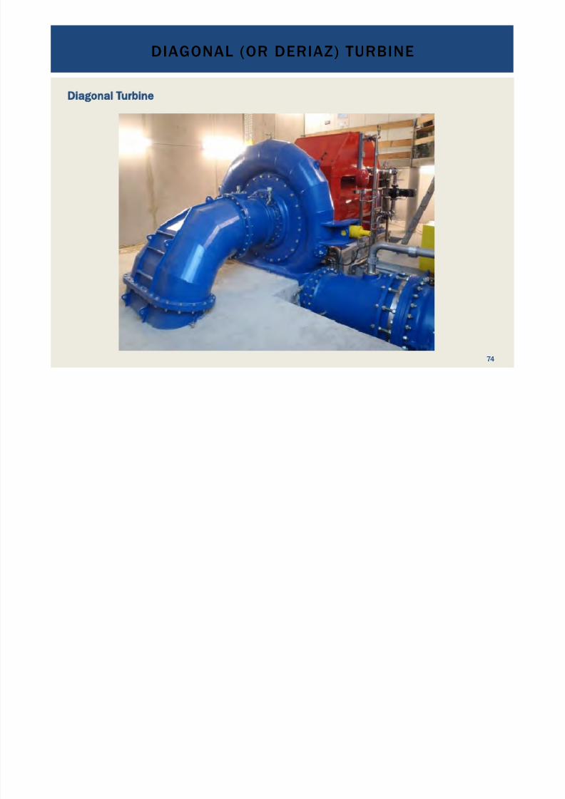
DIAGONAL (OR DERIAZ) TURBINE
74
Diagonal Turbine
7/18/2019 GEA Hydro Seminar
http://slidepdf.com/reader/full/gea-hydro-seminar-569195599756d 75/160
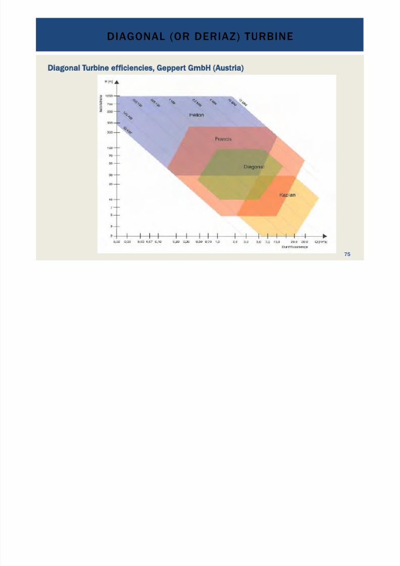
DIAGONAL (OR DERIAZ) TURBINE
75
Diagonal Turbine efficiencies, Geppert GmbH (Austria)
7/18/2019 GEA Hydro Seminar
http://slidepdf.com/reader/full/gea-hydro-seminar-569195599756d 76/160
Diagonal (Deriaz) turbines: Mix between Kaplan and Francis Turbine
• Reaction turbine
•
Shape similar to Francis Turbines•
Double regulated: guide vanes and blades are adjustable•
Medium heads 20 to about 140 m•
Medium and high discharges: 1.8 to 500 m3 /s
•
Capacity up to 100 MW per unit• Typically used for small and medium hydropower projects with storage
or run-of-river and high flow variability•
Moderate sensitivity to abrasion through suspended sediments•
Turbine efficiencies of up to some 95 %•
Efficiency curves flat through double regulated blades/guide vanes
•
High maintenance
DIAGONAL (OR DERIAZ) TURBINE
76
7/18/2019 GEA Hydro Seminar
http://slidepdf.com/reader/full/gea-hydro-seminar-569195599756d 77/160
DIAGONAL (OR DERIAZ) TURBINE
77
Diagonal Turbine

7/18/2019 GEA Hydro Seminar
http://slidepdf.com/reader/full/gea-hydro-seminar-569195599756d 78/160
DIAGONAL (OR DERIAZ) TURBINE
78
Diagonal Turbine

7/18/2019 GEA Hydro Seminar
http://slidepdf.com/reader/full/gea-hydro-seminar-569195599756d 79/160
79
HYDRO WHEELS
(a)
Breast wheel with cells
(b)
Breast wheel with blades
(c) Overshot wheel
(d) Undershot wheel

7/18/2019 GEA Hydro Seminar
http://slidepdf.com/reader/full/gea-hydro-seminar-569195599756d 80/160
80
HYDRO WHEELS
Breast shot hydro wheel

7/18/2019 GEA Hydro Seminar
http://slidepdf.com/reader/full/gea-hydro-seminar-569195599756d 81/160
81
HYDRO WHEELS
Overshot hydro wheel
7/18/2019 GEA Hydro Seminar
http://slidepdf.com/reader/full/gea-hydro-seminar-569195599756d 82/160
82
HYDRO WHEELS
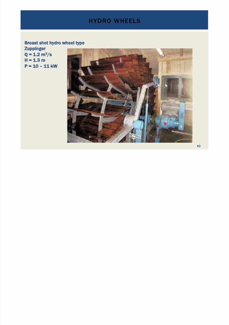
Breast shot hydro wheel type
Zuppinger
Q = 1.2 m
3
/s
H = 1.3 m
P = 10 – 11 kW
7/18/2019 GEA Hydro Seminar
http://slidepdf.com/reader/full/gea-hydro-seminar-569195599756d 83/160
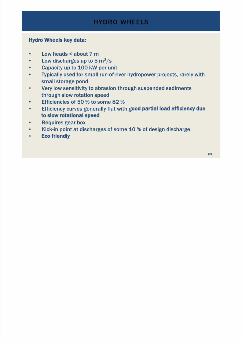
Hydro Wheels key data:
•
Low heads < about 7 m•
Low discharges up to 5 m3 /s•
Capacity up to 100 kW per unit•
Typically used for small run-of-river hydropower projects, rarely withsmall storage pond
•
Very low sensitivity to abrasion through suspended sedimentsthrough slow rotation speed
•
Efficiencies of 50 % to some 82 %•
Efficiency curves generally flat with good partial load efficiency due
to slow rotational speed
• Requires gear box
•
Kick-in point at discharges of some 10 % of design discharge• Eco friendly
HYDRO WHEELS
83
7/18/2019 GEA Hydro Seminar
http://slidepdf.com/reader/full/gea-hydro-seminar-569195599756d 84/160
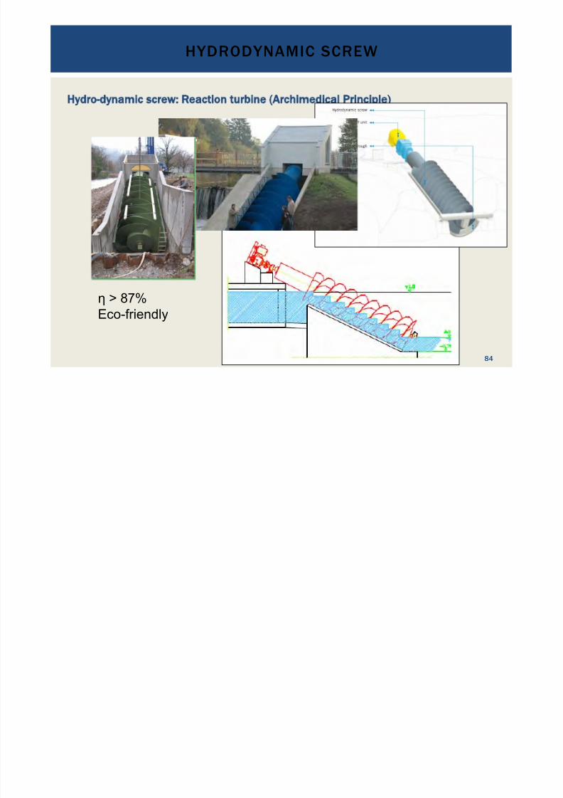
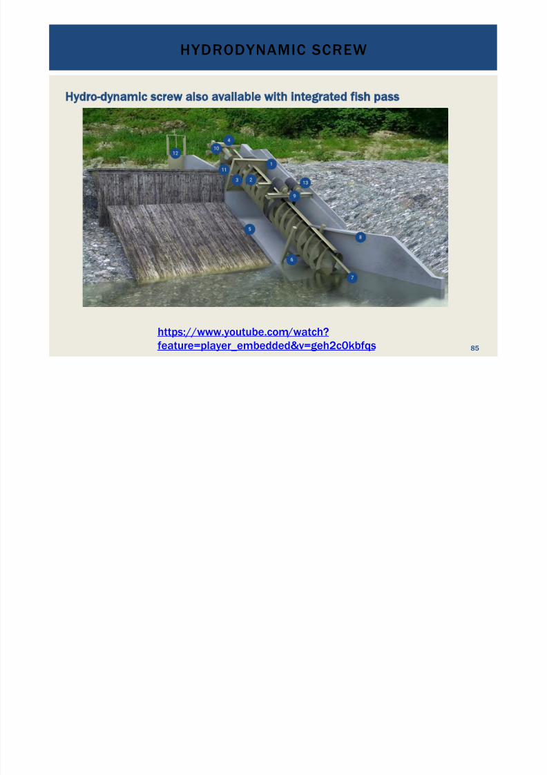
Hydro-dynamic screw: Reaction turbine (Archimedical Principle)
! > 87%Eco-friendly
HYDRODYNAMIC SCREW
84
7/18/2019 GEA Hydro Seminar
http://slidepdf.com/reader/full/gea-hydro-seminar-569195599756d 85/160
Hydro-dynamic screw also available with integrated fish pass
HYDRODYNAMIC SCREW
85
https://www.youtube.com /watch?feature=player_embedded&v=geh2c0kbfqs

7/18/2019 GEA Hydro Seminar
http://slidepdf.com/reader/full/gea-hydro-seminar-569195599756d 86/160
Hydro-dynamic screw also available with integrated fish pass
HYDRODYNAMIC SCREW
86
https://www.youtube.com /watch?feature=player_embedded&v=geh2c0kbfqs

7/18/2019 GEA Hydro Seminar
http://slidepdf.com/reader/full/gea-hydro-seminar-569195599756d 87/160
Hydrodynamic Screw key data:
•
Low heads of 1.5 to about 10 m•
Low discharges up to 5.5 m3 /s•
Capacity up to 300 kW per unit
HYDRODYNAMIC SCREW
87
7/18/2019 GEA Hydro Seminar
http://slidepdf.com/reader/full/gea-hydro-seminar-569195599756d 88/160
Hydrodynamic Screw key data:
•
Low heads < about 7 m•
Low discharges up to 5 m3 /s•
Capacity up to 100 kW per unit•
Typically used for small run-of-river hydropower projects, rarely withsmall storage pond
•
Very low sensitivity to abrasion through suspended sedimentsthrough slow rotation speed
•
Efficiencies of 50 % to some 82 %•
Efficiency curves generally flat with good partial load efficiency due
to slow rotational speed •
Kick-in point at discharges of some 10 % of design discharge
•
Breast wheel with cells, breast wheel with blades, overshot wheel or
undershot wheel
•
Eco friendly
HYDRODYNAMIC SCREW
88
7/18/2019 GEA Hydro Seminar
http://slidepdf.com/reader/full/gea-hydro-seminar-569195599756d 89/160
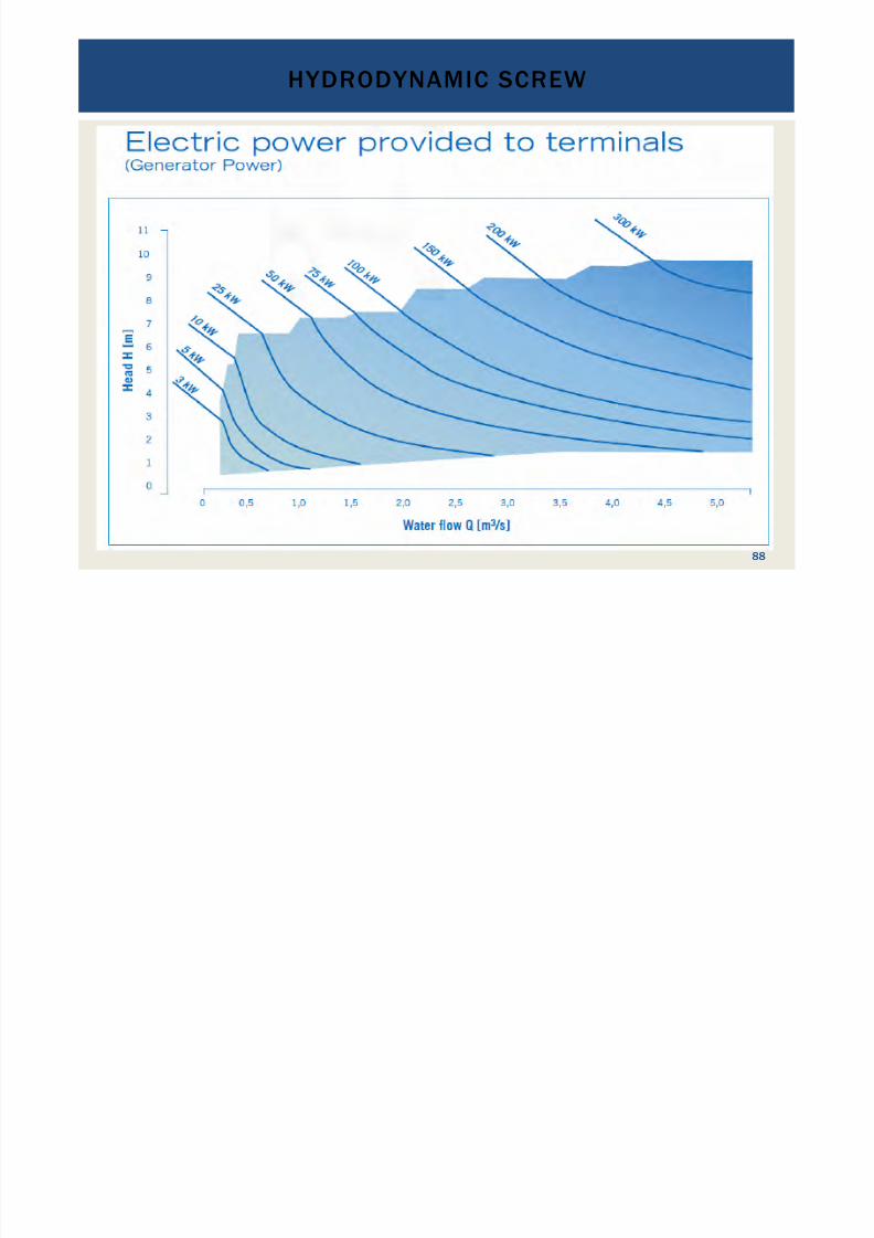
Hydrodynamic Screw key data:
•
Low heads of 1.5 to about 10 m•
Low discharges up to 5.5 m3 /s•
Capacity up to 300 kW per unit•
Typically used for small run-of-river hydropower projects•
Very low sensitivity to abrasion through suspended sediments
through slow rotation speed•
Efficiencies of up to some 87 %•
Efficiency curves generally flat with good partial load efficiency due
to slow rotational speed •
Eco friendly, optional with integrated fish lift
HYDRODYNAMIC SCREW
89
7/18/2019 GEA Hydro Seminar
http://slidepdf.com/reader/full/gea-hydro-seminar-569195599756d 90/160
PUMPS AS TURBINES
90
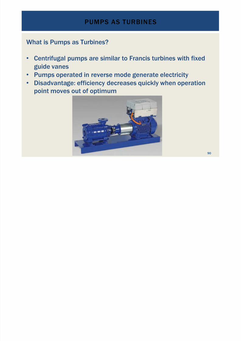
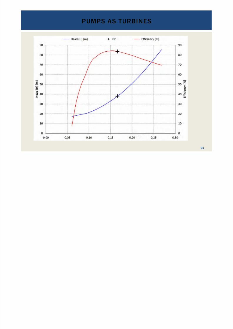
What is Pumps as Turbines?
• Centrifugal pumps are similar to Francis turbines with fixedguide vanes
• Pumps operated in reverse mode generate electricity• Disadvantage: efficiency decreases quickly when operation
point moves out of optimum
7/18/2019 GEA Hydro Seminar
http://slidepdf.com/reader/full/gea-hydro-seminar-569195599756d 91/160
PUMPS AS TURBINES
91
7/18/2019 GEA Hydro Seminar
http://slidepdf.com/reader/full/gea-hydro-seminar-569195599756d 92/160
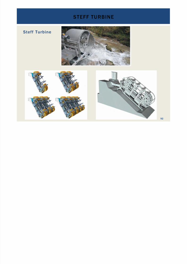
Steff Turbine
STEFF TURBINE
92
7/18/2019 GEA Hydro Seminar
http://slidepdf.com/reader/full/gea-hydro-seminar-569195599756d 93/160
DIVE TURBINE
93
7/18/2019 GEA Hydro Seminar
http://slidepdf.com/reader/full/gea-hydro-seminar-569195599756d 94/160
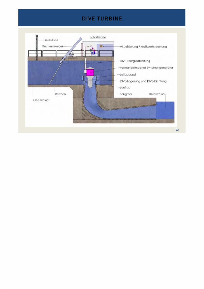
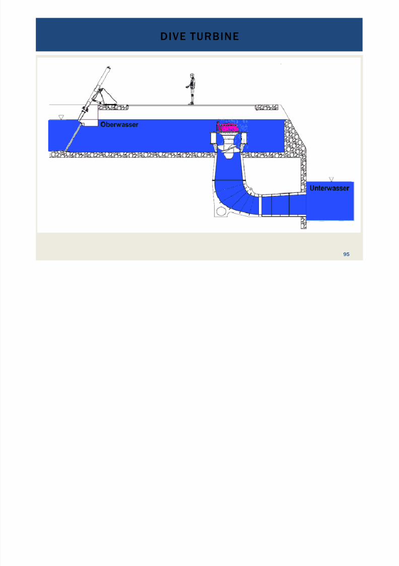
Dive Turbine key data:
•
Principle of a Kaplan Turbine•
Low heads of 2 to about 25 m•
Low to medium discharges of 0.6 to 40 m3 /s•
Capacity of 30 kW to 2 MW per unit•
Permanent magnet generator with frequency converter
•
Variable speed drive•
Typically used for small run-of-river hydropower projects•
Submersible design " no need for powerhouse•
Medium sensitivity to abrasion through suspended sediments•
Efficiencies of up to some 87 %
DIVE TURBINE
94
DIVE TURBINE
7/18/2019 GEA Hydro Seminar
http://slidepdf.com/reader/full/gea-hydro-seminar-569195599756d 95/160
Dive Turbine key data:
•
Principle of a Kaplan Turbine•
Low heads of 2 to about 25 m•
Low to medium discharges of 0.6 to 40 m3 /s•
Capacity of 30 kW to 2 MW per unit•
Typically used for small run-of-river hydropower projects
•
Submersible design " no need for powerhouse• Medium sensitivity to abrasion through suspended sediments
•
Efficiencies of up to some 87 %•
Efficiency curves generally flat with good partial load efficiency due
to slow rotational speed •
Eco friendly, optional with integrated fish lift
DIVE TURBINE
95
MICRO TURBINE COMPACT SYSTEMS

7/18/2019 GEA Hydro Seminar
http://slidepdf.com/reader/full/gea-hydro-seminar-569195599756d 96/160
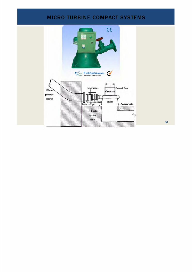
For very small projects compact turbine packages exist.
Example: Fuchun Industry from Shenzhen, China
•
Turgo and propeller type turbines•
Turgo:•
H between 12 m and 45 m;
•
Q between 0.003 and 0.120 m3
/s;• P between 0.3 and 300 kW
•
One or two nozzles•
One or three phase permanent magnet generator•
Propeller:•
H between 4 m and 11 m;
•
Q between 0.045 and 0.165 m3
/s;• P between 3.0 and 10.0 kW
•
See web-page: http://www.fuchunind.com
MICRO TURBINE COMPACT SYSTEMS
96
MICRO TURBINE COMPACT SYSTEMS
7/18/2019 GEA Hydro Seminar
http://slidepdf.com/reader/full/gea-hydro-seminar-569195599756d 97/160
MICRO TURBINE COMPACT SYSTEMS
97
MICRO TURBINE COMPACT SYSTEMS
7/18/2019 GEA Hydro Seminar
http://slidepdf.com/reader/full/gea-hydro-seminar-569195599756d 98/160
MICRO TURBINE COMPACT SYSTEMS
98
MICRO TURBINE COMPACT SYSTEMS
7/18/2019 GEA Hydro Seminar
http://slidepdf.com/reader/full/gea-hydro-seminar-569195599756d 99/160
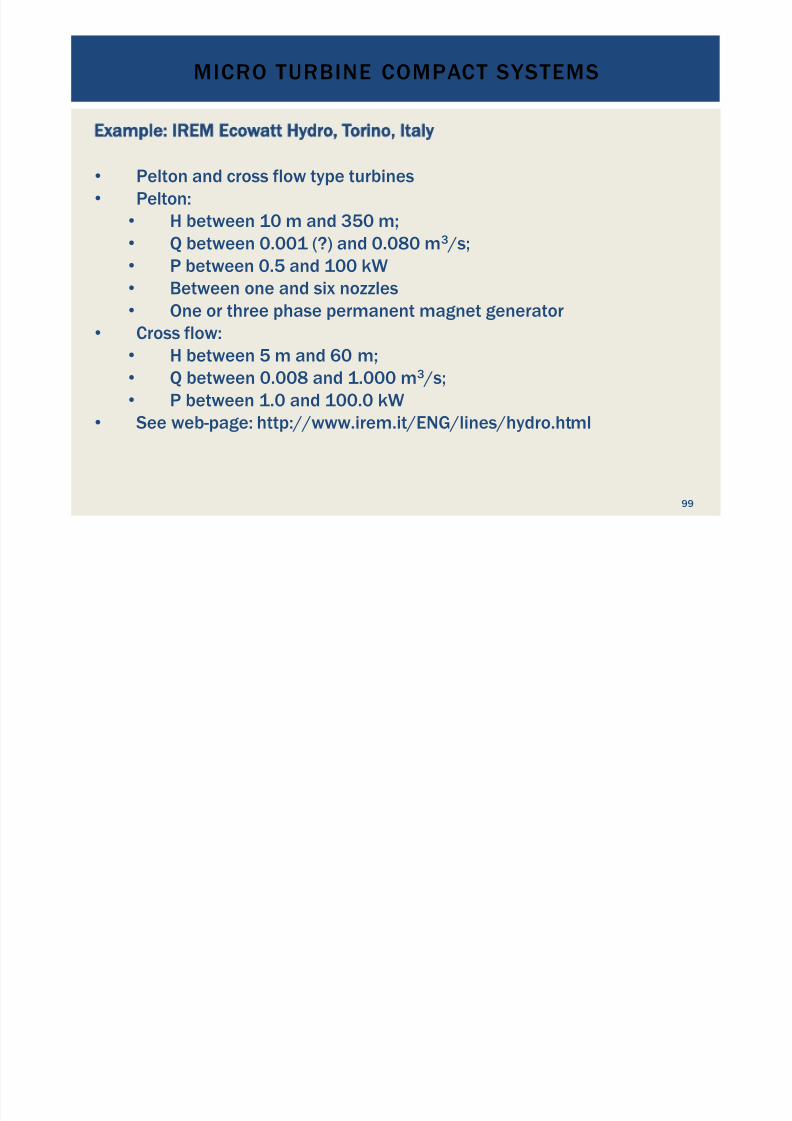
Example: IREM Ecowatt Hydro, Torino, Italy
•
Pelton and cross flow type turbines•
Pelton:•
H between 10 m and 350 m;•
Q between 0.001 (?) and 0.080 m3 /s;•
P between 0.5 and 100 kW
•
Between one and six nozzles• One or three phase permanent magnet generator
•
Cross flow:•
H between 5 m and 60 m;•
Q between 0.008 and 1.000 m3 /s;•
P between 1.0 and 100.0 kW
•
See web-page: http://www.irem.it/ENG/lines/hydro.html
MICRO TURBINE COMPACT SYSTEMS
99
MICRO TURBINE COMPACT SYSTEMS

7/18/2019 GEA Hydro Seminar
http://slidepdf.com/reader/full/gea-hydro-seminar-569195599756d 100/160
MICRO TURBINE COMPACT SYSTEMS
100
MICRO TURBINE COMPACT SYSTEMS

7/18/2019 GEA Hydro Seminar
http://slidepdf.com/reader/full/gea-hydro-seminar-569195599756d 101/160
MICRO TURBINE COMPACT SYSTEMS
101
MICRO TURBINE COMPACT SYSTEMS

7/18/2019 GEA Hydro Seminar
http://slidepdf.com/reader/full/gea-hydro-seminar-569195599756d 102/160
When ordering packaged systems:
•
Is the control system included or not?
• How much civil works are required?
• Warranty period?
•
Supply of spare parts and delivery time?
•
Labeling of the control system: English, Chinese, Italian,...?•
Easy to operate?
•
Shipping costs?
• Online or telephone support available?
MICRO TURBINE COMPACT SYSTEMS
102

7/18/2019 GEA Hydro Seminar
http://slidepdf.com/reader/full/gea-hydro-seminar-569195599756d 103/160
ENVIRONMENTAL AND
SOCIALCONSIDERATIONS
103
ENVIRONMENTAL IMPACT ASSESSMENT

7/18/2019 GEA Hydro Seminar
http://slidepdf.com/reader/full/gea-hydro-seminar-569195599756d 104/160
Importance:
!
Requirement (legal in most countries and/or forfinanciers)
! For macroeconomic cost-benefit analysis
! For microeconomic viability of the project
!
Anticipated irreversible adverse impacts on theenvironment may result in the discontinuation ofprojects!
ENVIRONMENTAL IMPACT ASSESSMENT
ENVIRONMENTAL IMPACT ASSESSMENT

7/18/2019 GEA Hydro Seminar
http://slidepdf.com/reader/full/gea-hydro-seminar-569195599756d 105/160
Main issues:
!
Loss of natural resources, habitats, biodiversity,ecosystem services
! Alteration of the natural environment and itsconsequences
!
Pollution and environmental degradation duringconstruction phase
! Noise pollution from power house (and other noisyequipment)
ENVIRONMENTAL IMPACT ASSESSMENT
ENVIRONMENTAL IMPACT ASSESSMENT
7/18/2019 GEA Hydro Seminar
http://slidepdf.com/reader/full/gea-hydro-seminar-569195599756d 106/160
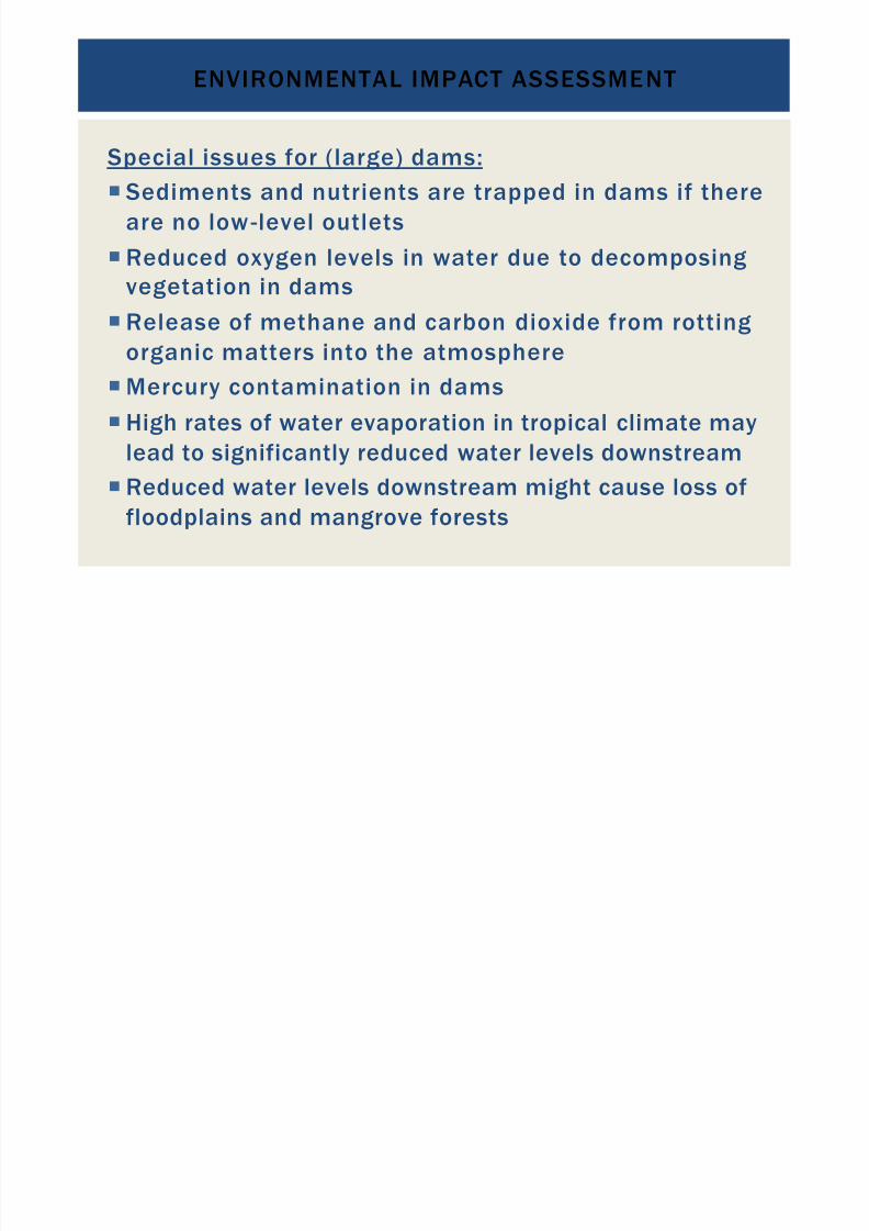
Special issues for (large) dams:
! Sediments and nutrients are trapped in dams if thereare no low-level outlets
! Reduced oxygen levels in water due to decomposingvegetation in dams
!
Release of methane and carbon dioxide from rottingorganic matters into the atmosphere
! Mercury contamination in dams
! High rates of water evaporation in tropical climate maylead to significantly reduced water levels downstream
!
Reduced water levels downstream might cause loss offloodplains and mangrove forests
ENVIRONMENTAL IMPACT ASSESSMENT
ENVIRONMENTAL IMPACT ASSESSMENT
7/18/2019 GEA Hydro Seminar
http://slidepdf.com/reader/full/gea-hydro-seminar-569195599756d 107/160
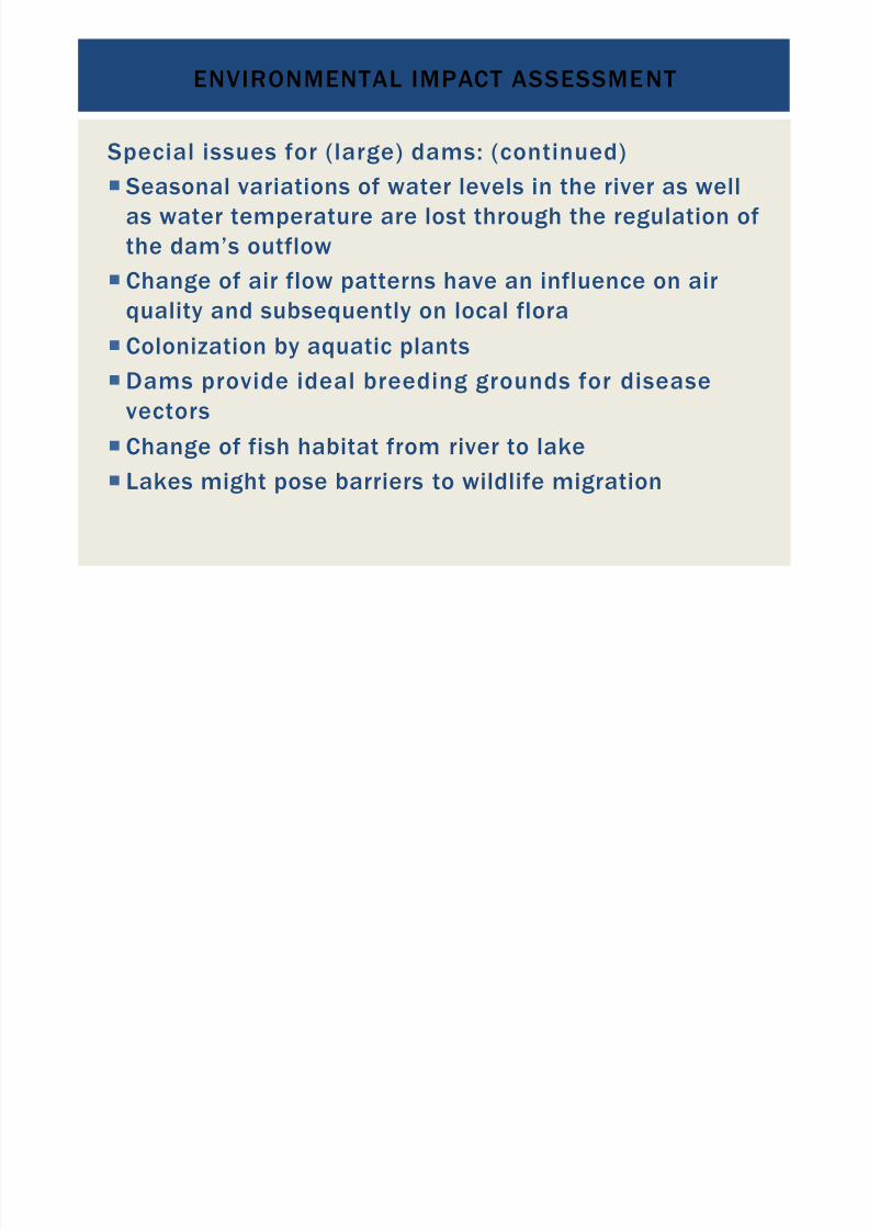
Special issues for (large) dams: (continued)
!
Seasonal variations of water levels in the river as wellas water temperature are lost through the regulation ofthe dam’s outflow
! Change of air flow patterns have an influence on air
quality and subsequently on local flora! Colonization by aquatic plants
! Dams provide ideal breeding grounds for diseasevectors
! Change of fish habitat from river to lake
!
Lakes might pose barriers to wildlife migration
ENVIRONMENTAL IMPACT ASSESSMENT
ENVIRONMENTAL IMPACT ASSESSMENT

7/18/2019 GEA Hydro Seminar
http://slidepdf.com/reader/full/gea-hydro-seminar-569195599756d 108/160
Questions to be answered by an EIA:
Are mitigation measures for all issues possible?
How much do they cost?
ENVIRONMENTAL IMPACT ASSESSMENT
SOCIAL IMPACT ASSESSMENT
7/18/2019 GEA Hydro Seminar
http://slidepdf.com/reader/full/gea-hydro-seminar-569195599756d 109/160
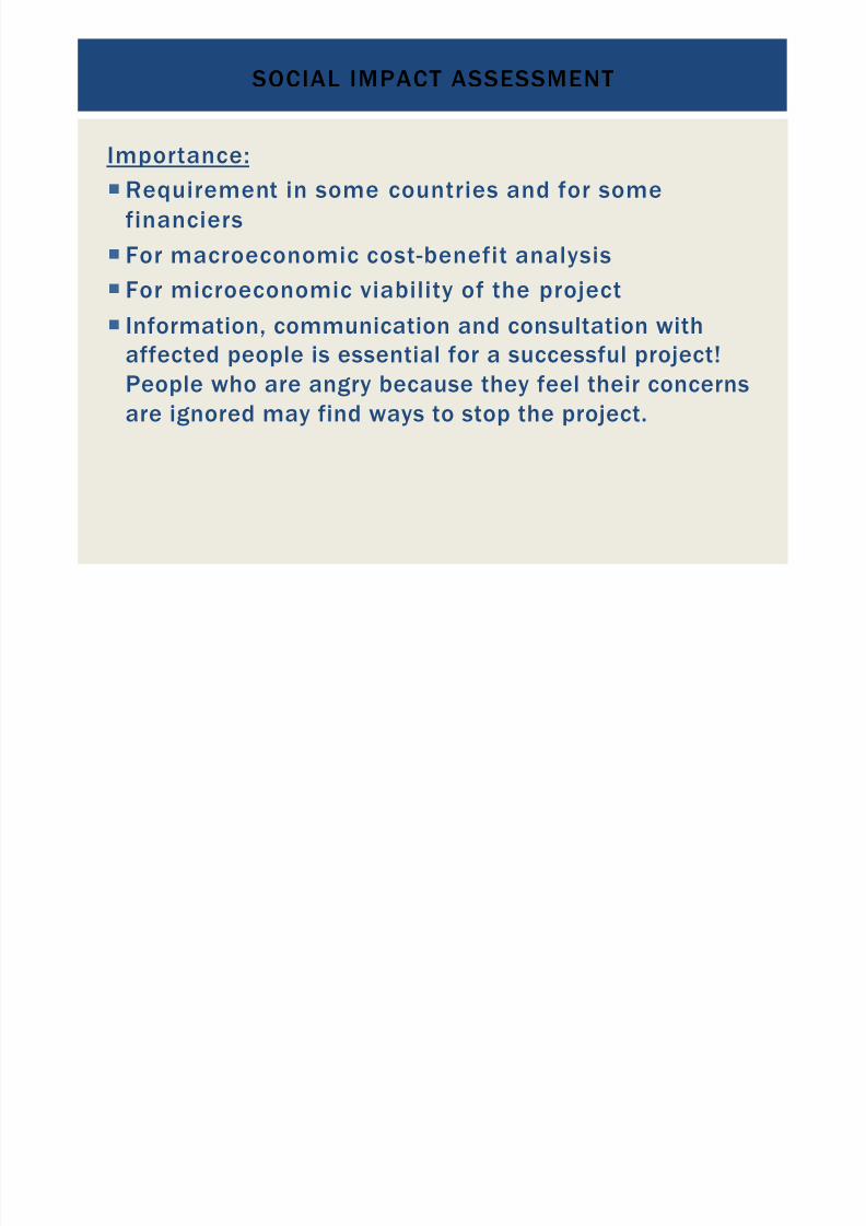
Importance:
! Requirement in some countries and for somefinanciers
! For macroeconomic cost-benefit analysis
! For microeconomic viability of the project
!
Information, communication and consultation withaffected people is essential for a successful project!People who are angry because they feel their concernsare ignored may find ways to stop the project.
SOCIAL IMPACT ASSESSMENT
SOCIAL IMPACT ASSESSMENT

7/18/2019 GEA Hydro Seminar
http://slidepdf.com/reader/full/gea-hydro-seminar-569195599756d 110/160
Main issues and mitigation measures to consider:
!
Communication, information and consultation
! Establish good communications channels with affectedpeople from the start of the project (and keep complaintsmanagement in place after construction is completed)
! Hold open information and consultation meetings for theaffected people at the beginning of the project and inregular intervals thereafter; involve the affected people inthe project planning
! Manage expectations carefully: ensure the localpopulation benefits from the project but does not create
expectations the project cannot fulfill
SOCIAL IMPACT ASSESSMENT
SOCIAL IMPACT ASSESSMENT

7/18/2019 GEA Hydro Seminar
http://slidepdf.com/reader/full/gea-hydro-seminar-569195599756d 111/160
Main issues and mitigation measures to consider:(Continued)
! Resettlement:
! Negotiate fair deals with communities that have to beresettled
!
Transparent decision-making processes and consultationswith the communities are essential
!
Pay attention to the following:! Land rights (customary and statutory land rights might be
overlapping, people might not have official land titles)
! Water rights
!
Gender equality! Indigenous people’s rights
SOCIAL IMPACT ASSESSMENT
SOCIAL IMPACT ASSESSMENT

7/18/2019 GEA Hydro Seminar
http://slidepdf.com/reader/full/gea-hydro-seminar-569195599756d 112/160
Main issues and mitigation measures to consider:(Continued)
! Compensation:
! For loss of houses and land, livelihoods, cultural/ religiousgoods and places, community services
!
Also consider communities downstream whose livelihoodsmight be endangered through changes in the ecosystems
! Might include training and initial resources for uptake ofnew livelihoods
SOCIAL IMPACT ASSESSMENT
SOCIAL IMPACT ASSESSMENT

7/18/2019 GEA Hydro Seminar
http://slidepdf.com/reader/full/gea-hydro-seminar-569195599756d 113/160
Main issues and mitigation measures to consider:(Continued)
! Health issues
! Loss of cultural heritage sites
! Noise pollution
!
Social disruptions
! Large, especially cross-border projects add politicalcomponent and issues with water rights and waterusage on a national level
SOCIAL IMPACT ASSESSMENT
SOCIAL IMPACT ASSESSMENT

7/18/2019 GEA Hydro Seminar
http://slidepdf.com/reader/full/gea-hydro-seminar-569195599756d 114/160
Positive social impacts might include:
! Development impulses through access to electricity
! Education benefits through access to electricity
! Health benefits through access to clean water
SOCIAL IMPACT ASSESSMENT
SOCIAL IMPACT ASSESSMENT

7/18/2019 GEA Hydro Seminar
http://slidepdf.com/reader/full/gea-hydro-seminar-569195599756d 115/160
The positive and negative impacts must be putin relation to one another!
SOCIAL IMPACT ASSESSMENT
SOCIAL IMPACT ASSESSMENT
7/18/2019 GEA Hydro Seminar
http://slidepdf.com/reader/full/gea-hydro-seminar-569195599756d 116/160
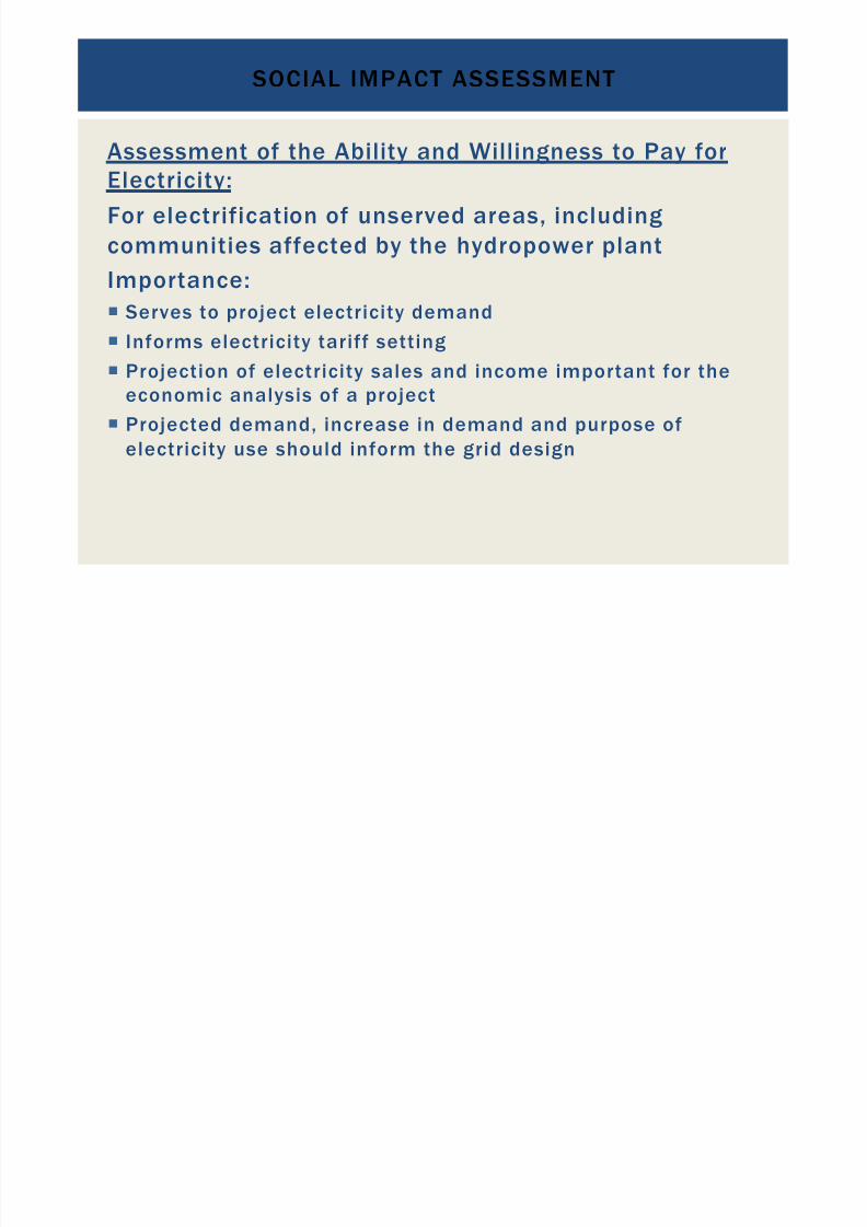
Assessment of the Ability and Willingness to Pay for
Electricity:For electrification of unserved areas, includingcommunities affected by the hydropower plant
Importance:! Serves to project electricity demand
! Informs electricity tariff setting
!
Projection of electricity sales and income important for theeconomic analysis of a project
! Projected demand, increase in demand and purpose ofelectricity use should inform the grid design
SOCIAL IMPACT ASSESSMENT
SOCIAL IMPACT ASSESSMENT
7/18/2019 GEA Hydro Seminar
http://slidepdf.com/reader/full/gea-hydro-seminar-569195599756d 117/160
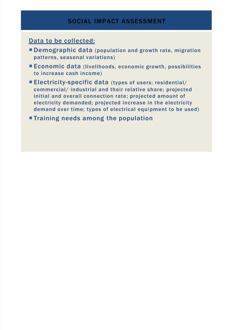
Data to be collected:
!
Demographic data (population and growth rate, migrationpatterns, seasonal variations)
! Economic data (livelihoods, economic growth, possibilitiesto increase cash income)
!
Electricity-specific data (types of users: residential/
commercial/ industrial and their relative share; projectedinitial and overall connection rate; projected amount ofelectricity demanded; projected increase in the electricitydemand over time; types of electrical equi pment to be used)
! Training needs among the population
INTERRELATION OF EIA AND SIA

7/18/2019 GEA Hydro Seminar
http://slidepdf.com/reader/full/gea-hydro-seminar-569195599756d 118/160
! Social and environmental impacts are closely
related, especially in developing countries, as peopleoften depend on the environment for their livelihoods
! People who are adversely affected by the project andfeel they do not benefit enough from the projectmight find environmental impacts as reasons to stop
the project!
! Access to electricity and clean water for communitiesaffected by the project should be ensured
ENVIRONMENTAL & SOCIAL IMPACT ASSESSMENT

7/18/2019 GEA Hydro Seminar
http://slidepdf.com/reader/full/gea-hydro-seminar-569195599756d 119/160
Conclusions:
! The importance of ESIAs must not be underestimated
! ESIAs should not be viewed as additional bureaucratichurdles to overcome, but as an instrument to inform thedebate about the costs and benefits of a proposedproject and its viability
! Impact mitigation costs must be considered in theeconomic viability analysis of a project
! Local population must participate in the benefits of theproject and not just bear the costs
ENVIRONMENTAL & SOCIAL IMPACT ASSESSMENT

7/18/2019 GEA Hydro Seminar
http://slidepdf.com/reader/full/gea-hydro-seminar-569195599756d 120/160
Conclusions (continued)
! Expectations, concerns and grievances of af fectedpopulation must be considered and managed carefully;otherwise conflicts will arise, which is very costly: angrypeople might find ways to stop projects
! High adverse environmental or social impacts may be a
reason to discontinue a project
! But: environmental and social costs should not becompared to status quo (zero development) but insteadto costs of realistic alternatives
7/18/2019 GEA Hydro Seminar
http://slidepdf.com/reader/full/gea-hydro-seminar-569195599756d 121/160
HYDROPOWER CIVILDESIGN OPTIONS:
DIFFERENCES,ADVANTAGES AND
DISADVANTAGES
121
HYDROPOWER PROJECT DESIGN

7/18/2019 GEA Hydro Seminar
http://slidepdf.com/reader/full/gea-hydro-seminar-569195599756d 122/160
122
Characteristic ciphers of hydropower projects
Development factorIs the ratio of mean river discharge and plant design discharge;
Plant FactorIs the ratio of the average power load of a plant to its rated capacity; (kW)
Capacity factorThe net capacity factor of a power plant is the ratio of its actual output over aperiod of time, to its potential output if it was possible for it to operate at fullnameplate capacity continuously over the same period of time. (kWh)
Availability factor
The availability factor of a power plant is the amount of time that it is able toproduce electricity over a certain time period.
HYDROPOWER PROJECT DESIGN

7/18/2019 GEA Hydro Seminar
http://slidepdf.com/reader/full/gea-hydro-seminar-569195599756d 123/160
123
Characteristic ciphers of hydropower projects
Load factorLoad factor for a power plant is the ratio between average load and peak load.
Operational efficiencyIs the ratio of the total electricity produced by the plant during a period of timecompared to the total potential electricity that could have been produced if theplant operated at 100 percent in the period.
HYDROPOWER PROJECT DESIGN
7/18/2019 GEA Hydro Seminar
http://slidepdf.com/reader/full/gea-hydro-seminar-569195599756d 124/160
124
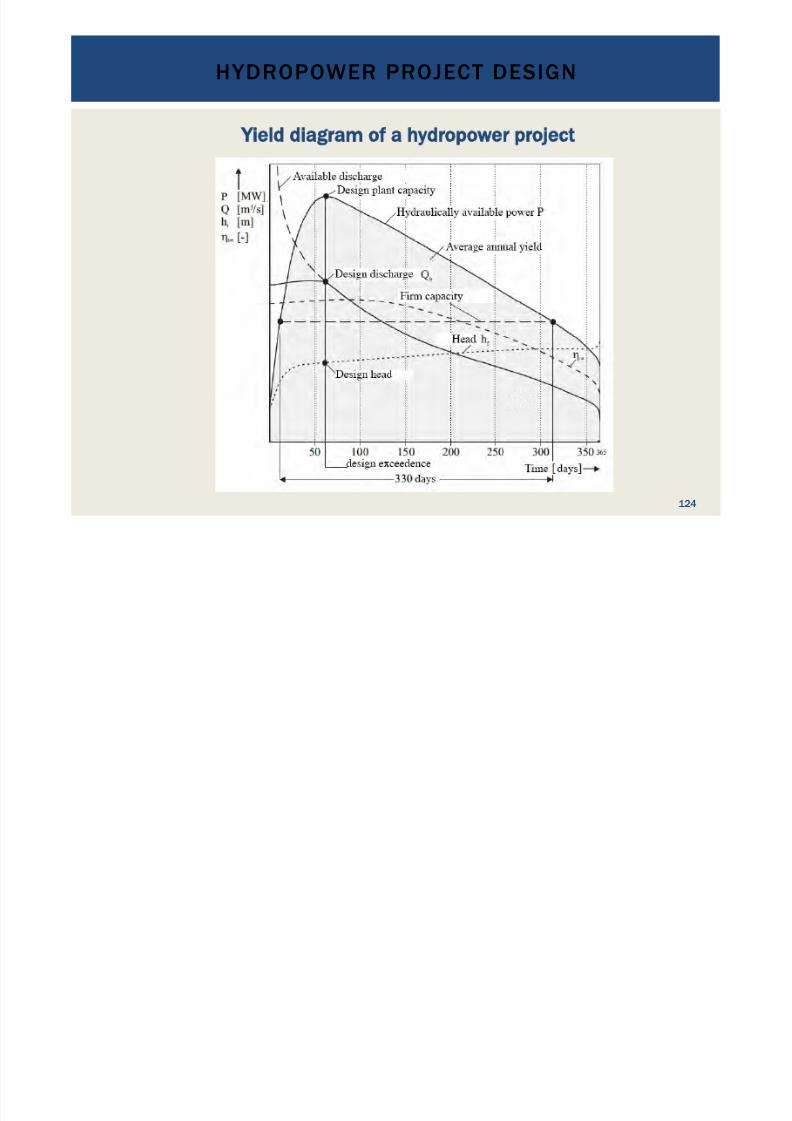
Yield diagram of a hydropower project
HYDROPOWER PROJECT DESIGN
7/18/2019 GEA Hydro Seminar
http://slidepdf.com/reader/full/gea-hydro-seminar-569195599756d 125/160
125
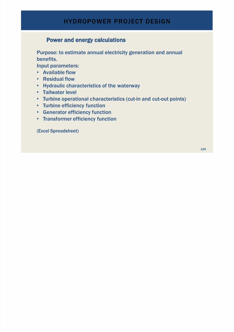
Power and energy calculations
Purpose: to estimate annual electricity generation and annualbenefits.Input parameters:•
Available flow•
Residual flow
•
Hydraulic characteristics of the waterway•
Tailwater level•
Turbine operational characteristics (cut-in and cut-out points)•
Turbine efficiency function•
Generator efficiency function•
Transformer efficiency function
(Excel Spreadsheet)
HYDROPOWER PROJECT DESIGN
7/18/2019 GEA Hydro Seminar
http://slidepdf.com/reader/full/gea-hydro-seminar-569195599756d 126/160
126
Plant optimization and design criteria
Hydropower projects can be optimized for different criteria:• Maximum power output;• Minimum electricity generation cost;• Maximum power availability and reliability;• Maximum flexibility;
• Provision of grid system services;• Pumped storage;• Other parameters that deem fit.
Depending on optimization objective the structural design will change.More details in a later session.
HYDROPOWER PROJECT DESIGN
7/18/2019 GEA Hydro Seminar
http://slidepdf.com/reader/full/gea-hydro-seminar-569195599756d 127/160
127
Plant optimization and design criteria
Each individual element of a hydropower plant is optimized usingvalue engineering criteria:
“Value engineering (VE) is systematic method to improve the "value"of goods or products and services by using an examination of
function.Value, as defined, is the ratio of function to cost. Value can thereforebe increased by either improving the function or reducing the cost.It is a primary tenet of value engineering that basic functions bepreserved and not be reduced as a consequence of pursuing valueimprovements.”(Source: Wikipedia)
HYDROPOWER PROJECT DESIGN

7/18/2019 GEA Hydro Seminar
http://slidepdf.com/reader/full/gea-hydro-seminar-569195599756d 128/160
128
Plant design criteria
For design criteria of hydraulic structures refer to:“Hydraulic Design Criteria, Volume 2” of the US Army Corps ofEngineers, 1987
• Powerhouse design criteria are mainly governed by the data
provided by the equipment manufacturer.• The electricity grid operator provides design criteria for electricalequipment.
•
Other design criteria may apply depending on the project.
PRINCIPLES OF GOOD PROJECT LAYOUT DESIGN
7/18/2019 GEA Hydro Seminar
http://slidepdf.com/reader/full/gea-hydro-seminar-569195599756d 129/160
! When visiting a site for the first time, or watching a topo map,
an initial project layout should be visualized!
Logically: Upstream = water in; Downstream = water out
!
Dam and reservoir or Run-Off River?
! Pressure head
! High head (h > 50 m)
! Medium head (15 m < h < 50 m)
! Low head (h < 15 m)
! Water availability
! General geology
! Solid rock
! Soil and rock
!
Soil and sand! Look for good geology for the various structures!
129
PRINCIPLES OF GOOD PROJECT LAYOUT DESIGN
7/18/2019 GEA Hydro Seminar
http://slidepdf.com/reader/full/gea-hydro-seminar-569195599756d 130/160
! Try to avoid areas of high population density for project design
" avoid need for resettlement and lengthy disputes!
Try to maximize the hydropower potential of each site with thelayout design. If the potential is more than the power neededfor supply, a stage wise construction can be envisaged.
! Integrate environmental considerations (fish ladders,minimum flow donation, and so on) in your design to avoid
additional cost when these items are required later in theprocess
! Consider sediment handling to be a serious aspect
! Do not omit the bottom outlet at dams and reser voirs
!
Design with realistic redundancy: black start hydropower plant
instead of diesel generators! Do not save on safety aspects
130
WATERWAY HYDRAULICS
7/18/2019 GEA Hydro Seminar
http://slidepdf.com/reader/full/gea-hydro-seminar-569195599756d 131/160
131
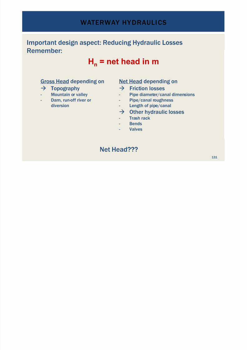
Gross Head depending on
! Topography - Mountain or valley
- Dam, run-off river or
diversion
Hn = net head in m
Net Head depending on
! Friction losses - Pipe diameter/canal dimensions
- Pipe/canal roughness
- Length of pipe/canal
! Other hydraulic losses - Trash rack
- Bends
- Valves
Important design aspect: Reducing Hydraulic Losses
Remember:
Net Head???
WATERWAY HYDRAULICS
7/18/2019 GEA Hydro Seminar
http://slidepdf.com/reader/full/gea-hydro-seminar-569195599756d 132/160
132
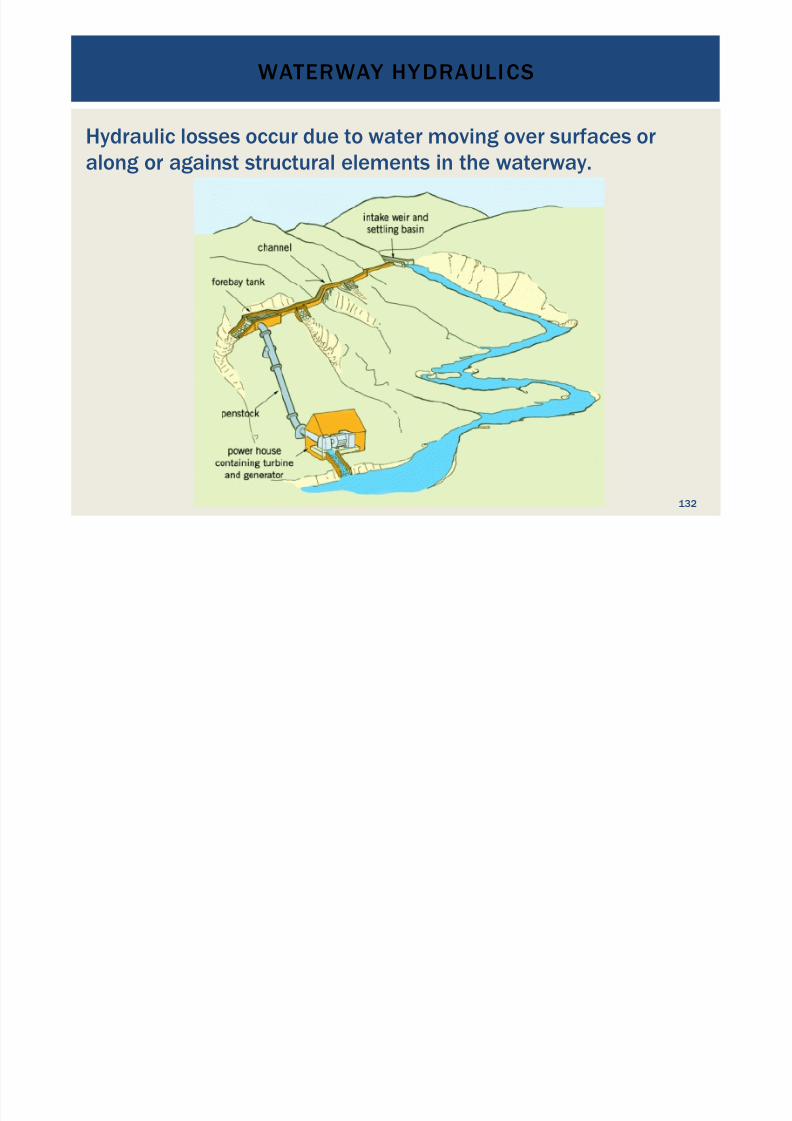
Hydraulic losses occur due to water moving over surfaces or
along or against structural elements in the waterway.
WATERWAY HYDRAULICS
7/18/2019 GEA Hydro Seminar
http://slidepdf.com/reader/full/gea-hydro-seminar-569195599756d 133/160
133
Losses are caused mainly by the water’s viscosity.
Inner friction converts loss energy into
•
heat,• turbulence, and• sound energy
WATERWAY HYDRAULICS
7/18/2019 GEA Hydro Seminar
http://slidepdf.com/reader/full/gea-hydro-seminar-569195599756d 134/160
134
Hydraulic losses typically originate from:
• Water intake• Trash rack• Friction losses in open channels• Desilting chamber due to deceleration of water velocity• Pipeline intake, forebay• Friction losses in pipelines• Valves and other fittings• Bends in pipes and channels• Changes in cross section size• Bifurcations and merging y-pieces and similar• Losses in the turbine itself; these are usually included in the
turbine efficiency• Draft tube• Tailrace channel turbulence
WATERWAY HYDRAULICS
7/18/2019 GEA Hydro Seminar
http://slidepdf.com/reader/full/gea-hydro-seminar-569195599756d 135/160
135
• Calculation of the hydraulic losses " hydromechanics
principles• Main sources of hydraulic losses: friction losses in open
channels and pipelines, bend losses and valve losses• Poorly designed structures: also desilting basin losses and
changes in cross section area are significant
" good understanding of the hydraulic principles is importantto establish good hydropower designs
WATERWAY HYDRAULICS
7/18/2019 GEA Hydro Seminar
http://slidepdf.com/reader/full/gea-hydro-seminar-569195599756d 136/160
136
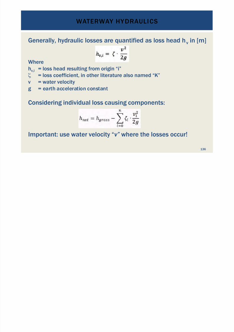
Generally, hydraulic losses are quantified as loss head hv in [m]
Wherehv,i = loss head resulting from origin “i”! = loss coefficient, in other literature also named “K”v = water velocity
g = earth acceleration constant
Considering individual loss causing components:
Important: use water velocity “v” where the losses occur!
WATERWAY HYDRAULICS
7/18/2019 GEA Hydro Seminar
http://slidepdf.com/reader/full/gea-hydro-seminar-569195599756d 137/160
137
Where to get loss coefficients from?
" Established from physical experiments for a multitude offittings, intake shapes and surfaces
" Good practical guide is “Internal Flow Systems” by D.S.Miller(Volume 5 in the BHRA Fluid Engineering Series)
The loss head depends on the discharge through the waterwayand is proportional to the square of the discharge.
Remember: Q = v * A " v = Q/A and v2 = Q2 /A2
WATERWAY HYDRAULICS
7/18/2019 GEA Hydro Seminar
http://slidepdf.com/reader/full/gea-hydro-seminar-569195599756d 138/160
138
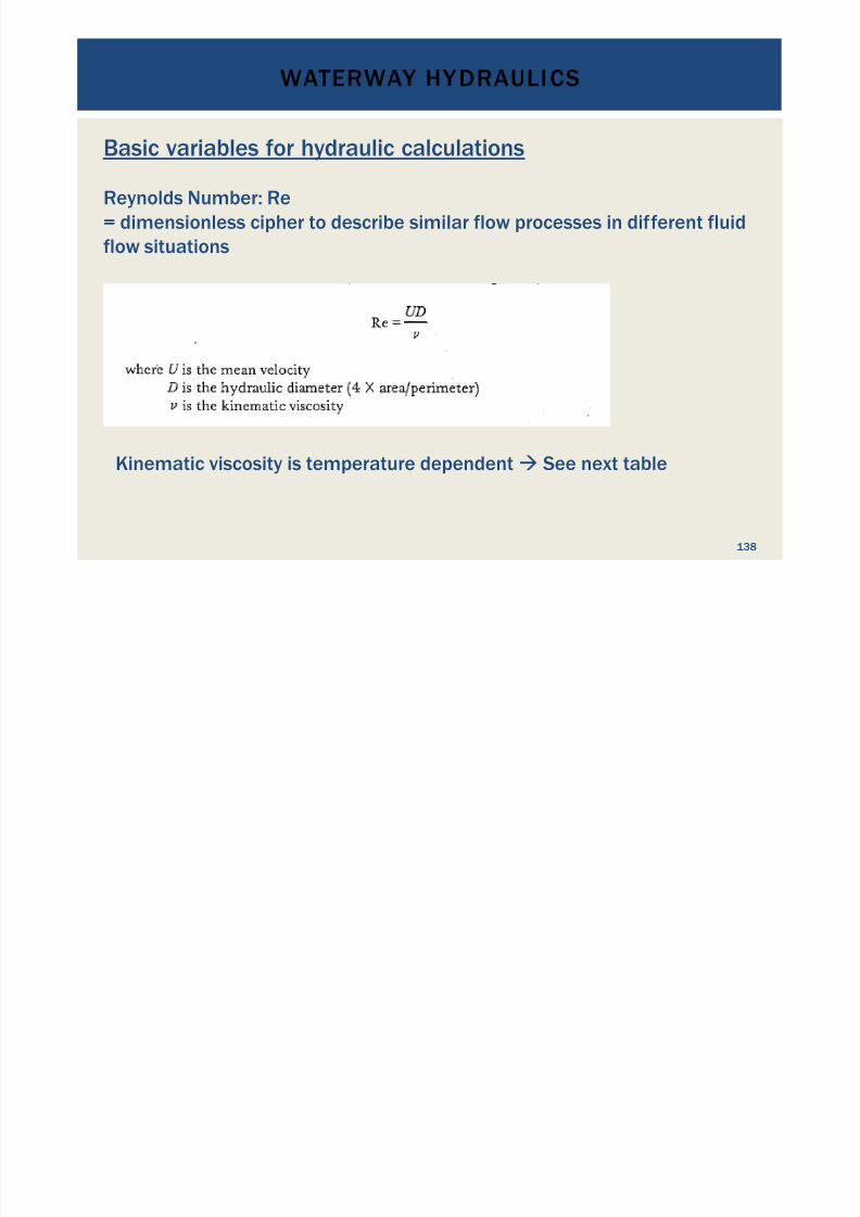
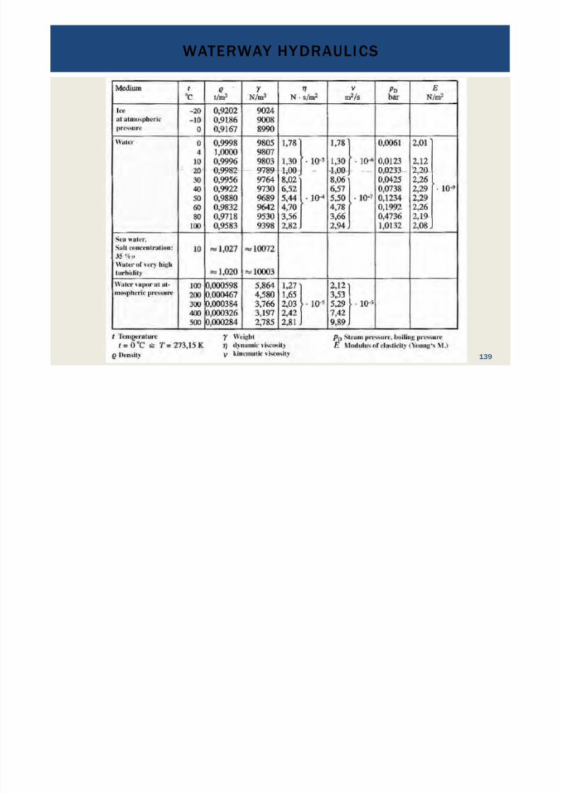
Basic variables for hydraulic calculations
Reynolds Number: Re= dimensionless cipher to describe similar flow processes in different fluidflow situations
Kinematic viscosity is temperature dependent " See next table
WATERWAY HYDRAULICS
7/18/2019 GEA Hydro Seminar
http://slidepdf.com/reader/full/gea-hydro-seminar-569195599756d 139/160
139
WATERWAY HYDRAULICS
7/18/2019 GEA Hydro Seminar
http://slidepdf.com/reader/full/gea-hydro-seminar-569195599756d 140/160
140
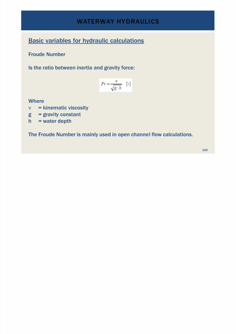
Basic variables for hydraulic calculations
Froude Number
Is the ratio between inertia and gravity force:
Where" = kinematic viscosityg = gravity constanth = water depth
The Froude Number is mainly used in open channel flow calculations.
WATERWAY HYDRAULICS

7/18/2019 GEA Hydro Seminar
http://slidepdf.com/reader/full/gea-hydro-seminar-569195599756d 141/160
141
Pipe losses
WATERWAY HYDRAULICS
7/18/2019 GEA Hydro Seminar
http://slidepdf.com/reader/full/gea-hydro-seminar-569195599756d 142/160
142
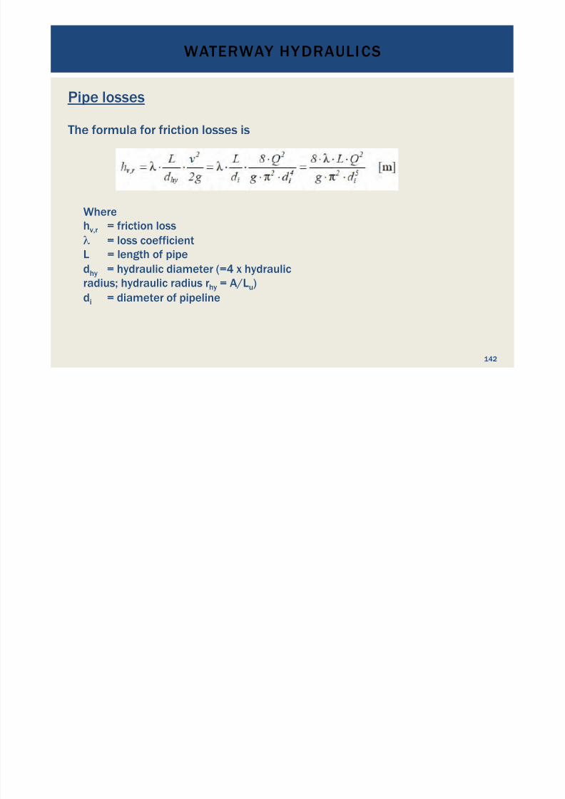
Pipe losses
The formula for friction losses is
Wherehv,r = friction loss# = loss coefficientL = length of pipedhy = hydraulic diameter (=4 x hydraulicradius; hydraulic radius rhy = A/Lu)di = diameter of pipeline
WATERWAY HYDRAULICS
7/18/2019 GEA Hydro Seminar
http://slidepdf.com/reader/full/gea-hydro-seminar-569195599756d 143/160
143
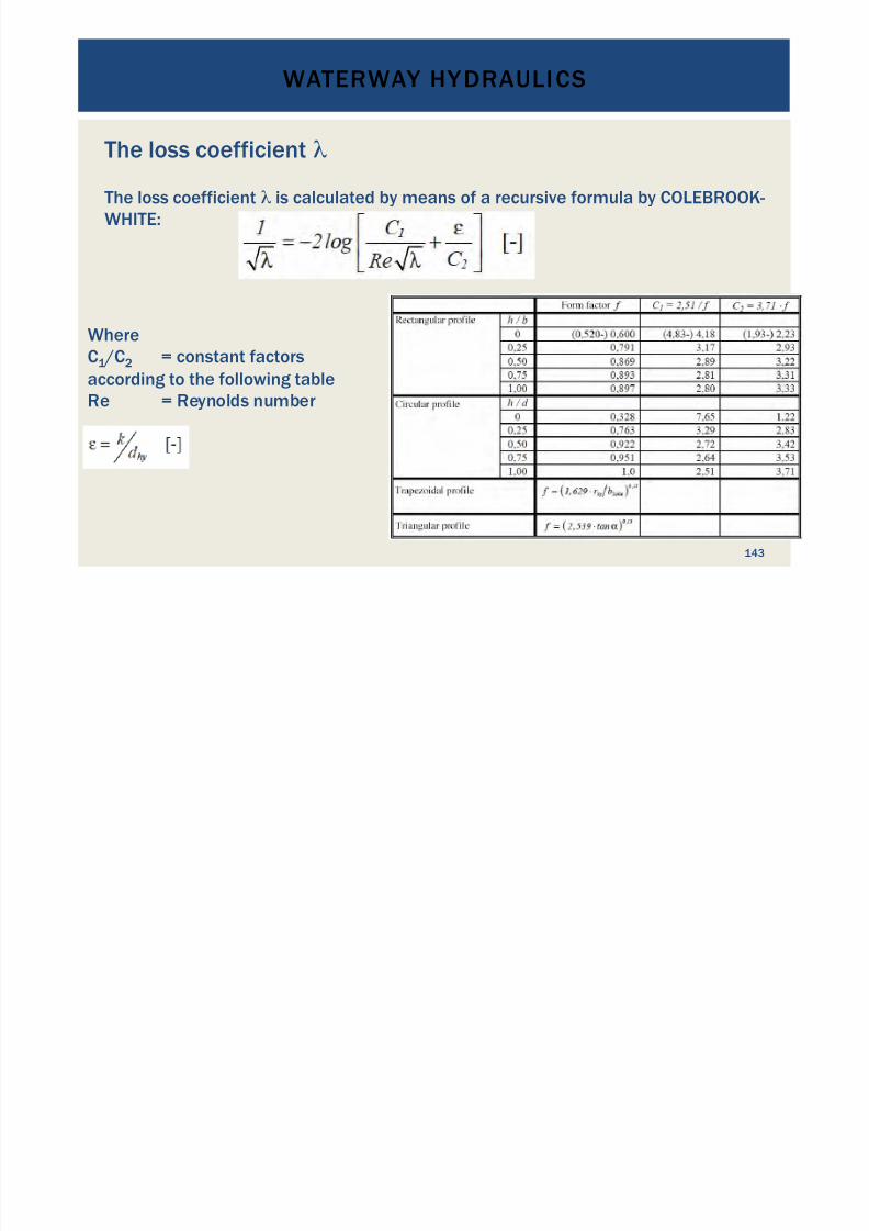
The loss coefficient #
The loss coefficient # is calculated by means of a recursive formula by COLEBROOK-WHITE:
WhereC1 /C2 = constant factorsaccording to the following tableRe = Reynolds number
WATERWAY HYDRAULICS

7/18/2019 GEA Hydro Seminar
http://slidepdf.com/reader/full/gea-hydro-seminar-569195599756d 144/160
144
The loss coefficient #
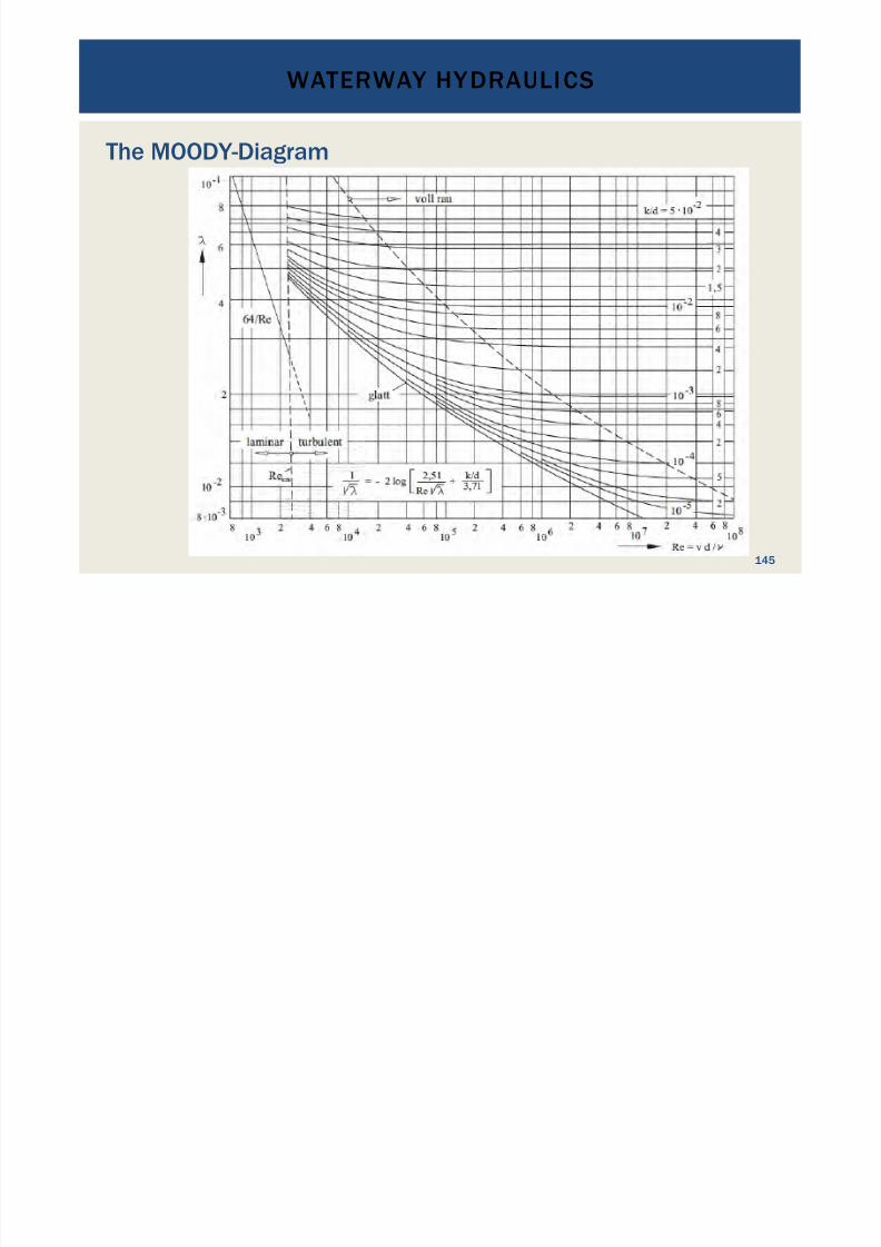
For completely filled circular pipelines the loss coefficient # is calculated by
Wherek = hydraulic roughness in mmdhy = hydraulic diameter in mm (!)
For simplicity, $ can be obtained from the MOODY-Diagram:
WATERWAY HYDRAULICS
7/18/2019 GEA Hydro Seminar
http://slidepdf.com/reader/full/gea-hydro-seminar-569195599756d 145/160
145
The MOODY-Diagram
WATERWAY HYDRAULICS
7/18/2019 GEA Hydro Seminar
http://slidepdf.com/reader/full/gea-hydro-seminar-569195599756d 146/160
146
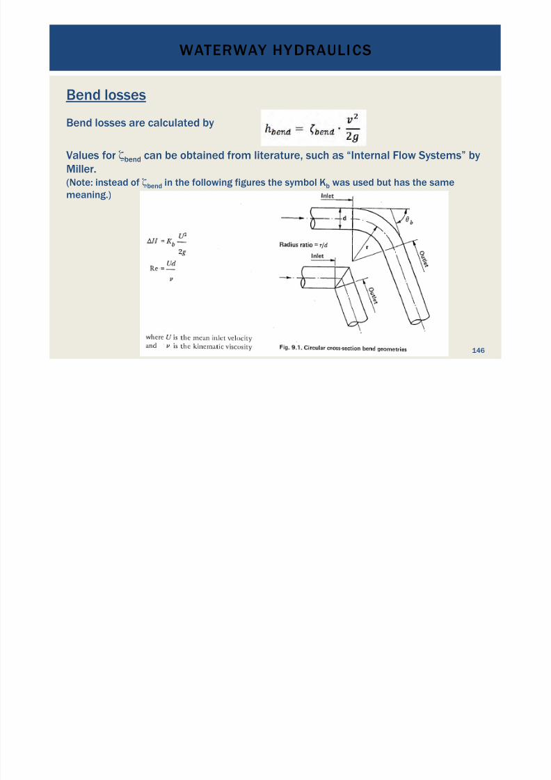
Bend losses
Bend losses are calculated by
Values for !bend can be obtained from literature, such as “Internal Flow Systems” byMiller.(Note: instead of !bend in the following figures the symbol Kb was used but has the samemeaning.)
WATERWAY HYDRAULICS
7/18/2019 GEA Hydro Seminar
http://slidepdf.com/reader/full/gea-hydro-seminar-569195599756d 147/160
147
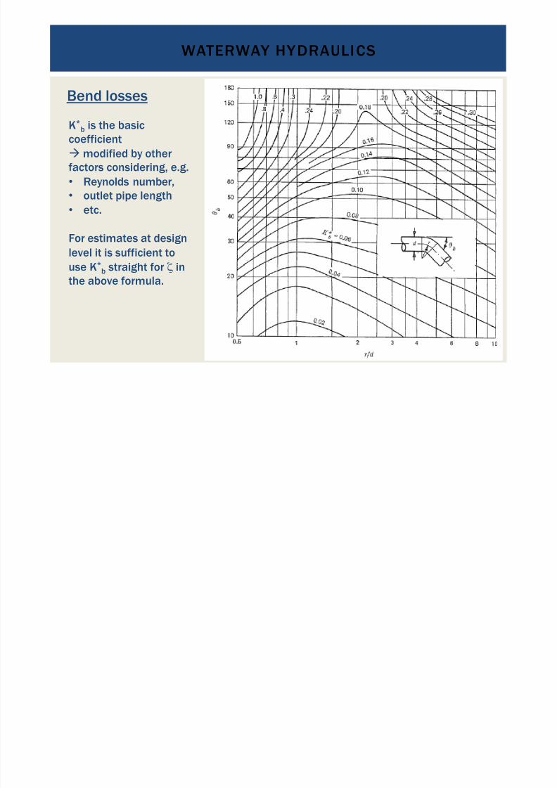
Bend losses
K*b is the basic
coefficient" modified by otherfactors considering, e.g.• Reynolds number,• outlet pipe length
•
etc.
For estimates at designlevel it is sufficient touse K*
b straight for ! inthe above formula.
WATERWAY HYDRAULICS
7/18/2019 GEA Hydro Seminar
http://slidepdf.com/reader/full/gea-hydro-seminar-569195599756d 148/160
148
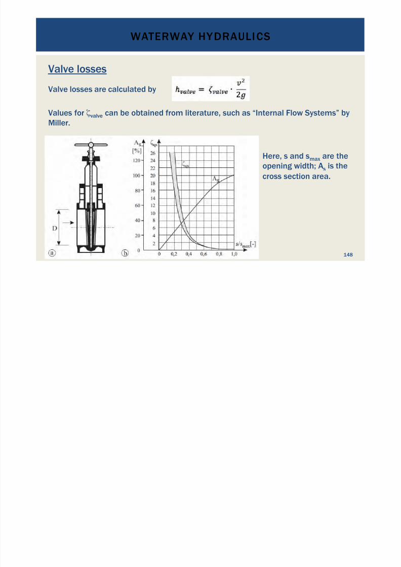
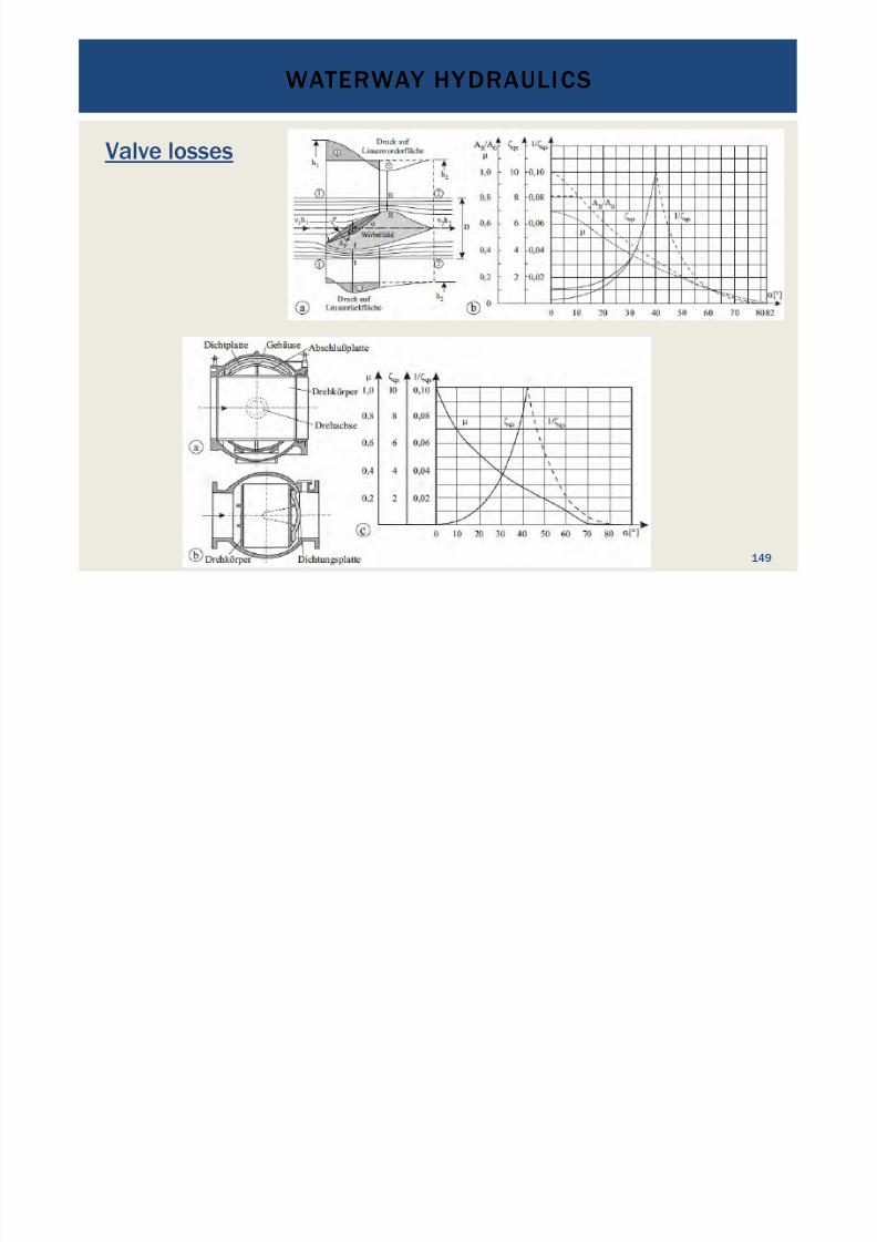
Valve losses
Valve losses are calculated by
Values for !valve can be obtained from literature, such as “Internal Flow Systems” byMiller.
Here, s and smax are theopening width; As is thecross section area.
WATERWAY HYDRAULICS
7/18/2019 GEA Hydro Seminar
http://slidepdf.com/reader/full/gea-hydro-seminar-569195599756d 149/160
149
Valve losses
WATERWAY HYDRAULICS
7/18/2019 GEA Hydro Seminar
http://slidepdf.com/reader/full/gea-hydro-seminar-569195599756d 150/160
150
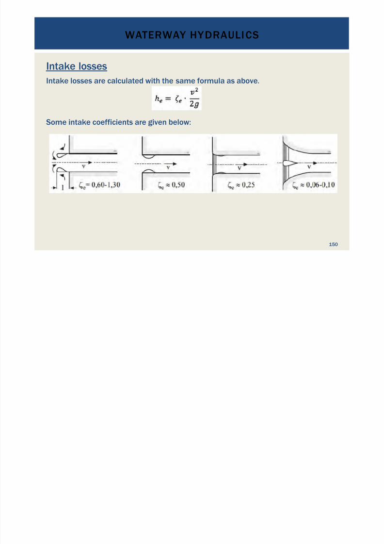
Intake losses
Intake losses are calculated with the same formula as above.
Some intake coefficients are given below:
WATERWAY HYDRAULICS
7/18/2019 GEA Hydro Seminar
http://slidepdf.com/reader/full/gea-hydro-seminar-569195599756d 151/160
151
Hydraulic Transients - Water Hammer Effect
•
Water has a mass m = % * VWherem = mass% = densityV = volume
•
Closing or opening a valve causes change of velocity
•
Change of velocity causes an impulse with impulse force•
The impulse force shows as pressure change (up or down)• The resulting transient process is known as “Water Hammer”
•
The magnitude of pressure rise depends on the time it takes to close avalve
• Generally speaking, it depends on the deceleration rate %v/%t
WATERWAY HYDRAULICS

7/18/2019 GEA Hydro Seminar
http://slidepdf.com/reader/full/gea-hydro-seminar-569195599756d 152/160
152
Hydraulic Transients - Water Hammer Effect
The magnitude of pressure variation in the pipe depends on:
•
Density of the water or liquid;•
Length of the pipeline;•
Diameter of the pipeline, which defines the water velocity;•
Modulus of elasticity of the pipe wall or tunnel wall;
•
Difference between initial and final velocity;• Time to reduce the speed from its initial to its final value.
• Generally: softer pipe walls " lower sound propagation speed in water" slower propagation of the pressure waves.
•
Higher water velocities " greater pressure modifications
WATERWAY HYDRAULICS
7/18/2019 GEA Hydro Seminar
http://slidepdf.com/reader/full/gea-hydro-seminar-569195599756d 153/160
153
Hydraulic Transients - Water Hammer Effect
To calculate the pressure rise, various methodologies are applied:
•
Finite element and finite difference methods;•
“Characteristics method” using simple differential equations•
Theory of elastic water column•
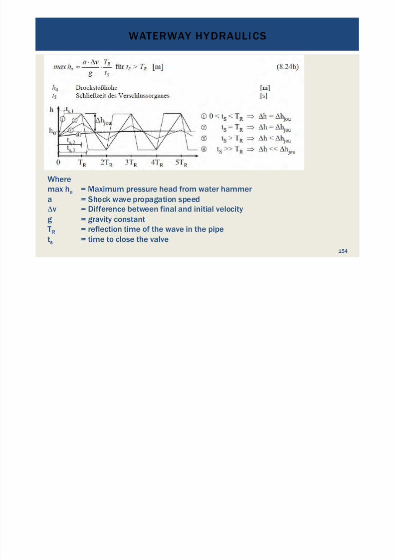
For rough estimates the formula according to Joukowsky is commonly
used:
WATERWAY HYDRAULICS
7/18/2019 GEA Hydro Seminar
http://slidepdf.com/reader/full/gea-hydro-seminar-569195599756d 154/160
154
Wheremax ha = Maximum pressure head from water hammera = Shock wave propagation speed&v = Difference between final and initial velocity
g = gravity constantTR = reflection time of the wave in the pipets = time to close the valve
WATERWAY HYDRAULICS
7/18/2019 GEA Hydro Seminar
http://slidepdf.com/reader/full/gea-hydro-seminar-569195599756d 155/160
155
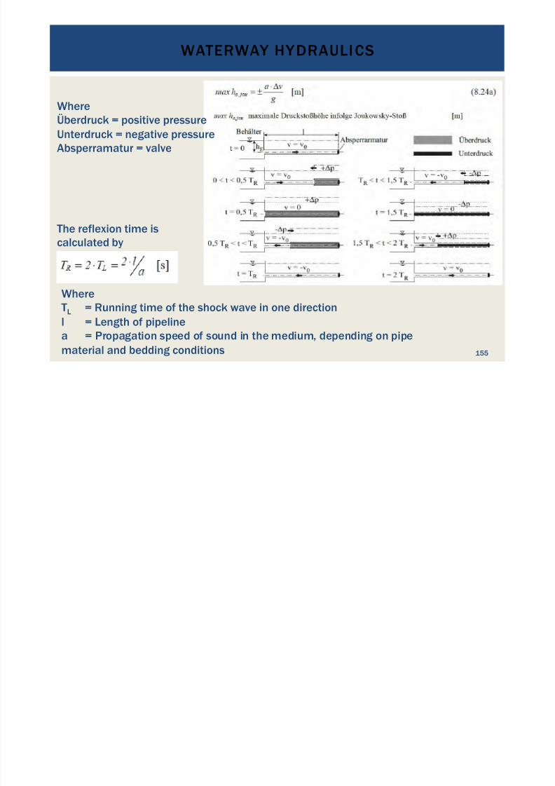
Where
Überdruck = positive pressureUnterdruck = negative pressureAbsperramatur = valve
The reflexion time iscalculated by
Where
TL = Running time of the shock wave in one directionl = Length of pipelinea = Propagation speed of sound in the medium, depending on pipematerial and bedding conditions
WATERWAY HYDRAULICS
7/18/2019 GEA Hydro Seminar
http://slidepdf.com/reader/full/gea-hydro-seminar-569195599756d 156/160
156
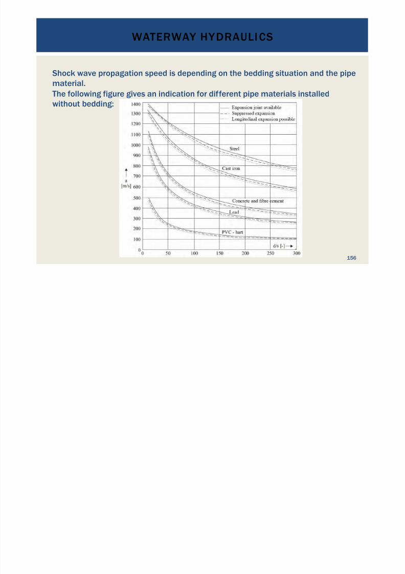
Shock wave propagation speed is depending on the bedding situation and the pipe
material.The following figure gives an indication for different pipe materials installedwithout bedding:
WATERWAY HYDRAULICS
7/18/2019 GEA Hydro Seminar
http://slidepdf.com/reader/full/gea-hydro-seminar-569195599756d 157/160
157
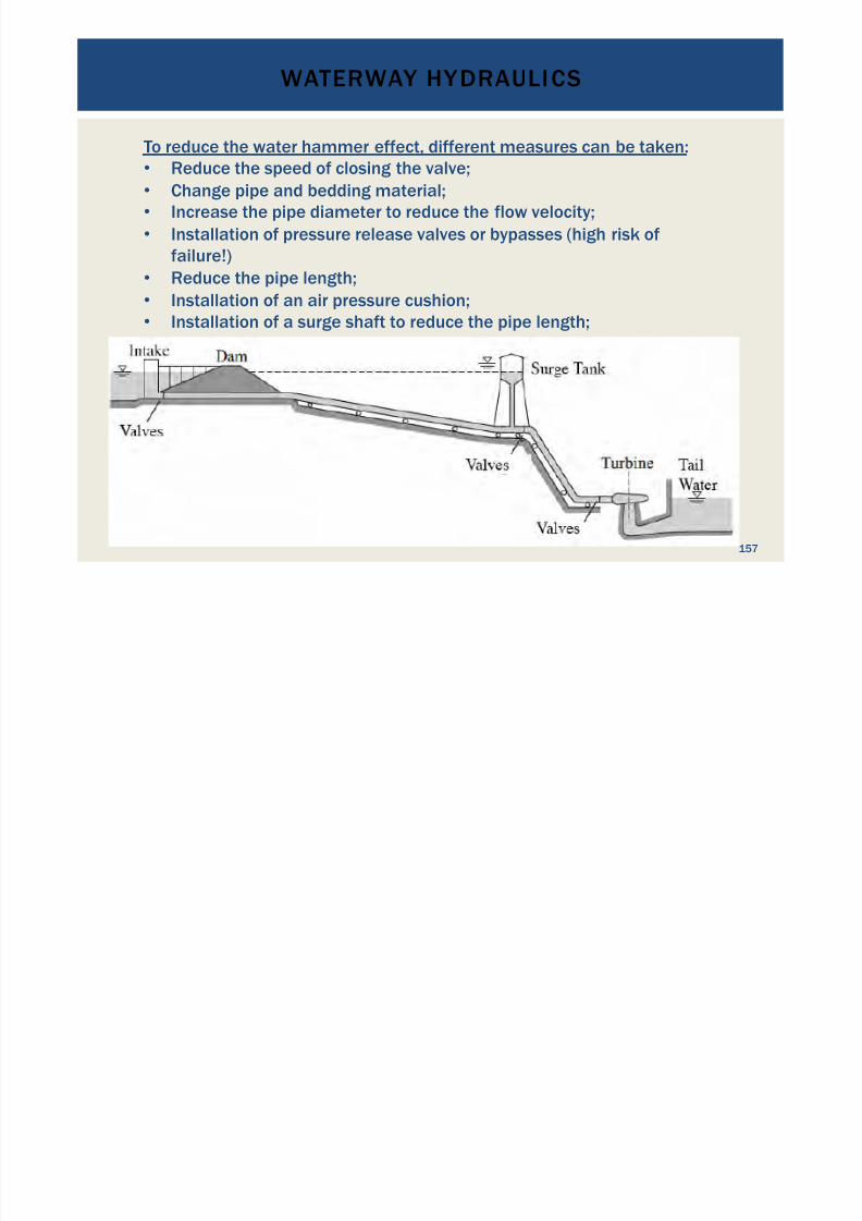
To reduce the water hammer effect, different measures can be taken:• Reduce the speed of closing the valve;•
Change pipe and bedding material;• Increase the pipe diameter to reduce the flow velocity;• Installation of pressure release valves or bypasses (high risk of
failure!)• Reduce the pipe length;• Installation of an air pressure cushion;
•
Installation of a surge shaft to reduce the pipe length;
DRAWING CONCLUSIONS FROM THE RESULTS,QUESTION AND ANSWER SESSION

7/18/2019 GEA Hydro Seminar
http://slidepdf.com/reader/full/gea-hydro-seminar-569195599756d 158/160
186
Questions? Comments?

7/18/2019 GEA Hydro Seminar
http://slidepdf.com/reader/full/gea-hydro-seminar-569195599756d 159/160
CONTACT
E-mail: [email protected]: http://www.sven-homscheid.com
THANK YOU FOR YOURATTENTION!
187
REFERENCES

7/18/2019 GEA Hydro Seminar
http://slidepdf.com/reader/full/gea-hydro-seminar-569195599756d 160/160
! Magazine „Hydro Review Worldwide, edition July-August 2015“
!
https://www.sensefly.com/drones/ebee-rtk.html! www.wikipedia.com
!
„Wasserkraftanlagen“; Giesecke; Mosonyi; 2003; ISBN3-540-44391-6
! „Hydraulik fuer Bauingenieure“; Heinemann/Paul; ISBN3-519-05082-x
!
http://www.hydroconnect.at
!
http://www.wasserradfabrik.de/wasserkraftraeder.html
!
http://goecke.de/Produkte/