Embed Size (px)
Citation preview

GE Sensing & Inspection Technologies
DigitalFlow™ GS868Panametrics Steam Ultrasonic Mass Flowmeter
Service Manual (1 and 2-Channel)

GE Sensing & Inspection Technologies
DigitalFlow™ GS868Panametrics Steam Ultrasonic Mass Flowmeter
Service Manual (1 and 2-Channel)910-190SD1March 2008
The DigitalFlow GS868 is a GE Panametrics product. GE Panametrics has joined other GE high-technology businesses under a new name—GE Sensing & Inspection Technologies.

March 2008
Warranty Each instrument manufactured by GE Sensing, Inc. is warranted to be free from defects in material and workmanship. Liability under this warranty is limited to restoring the instrument to normal operation or replacing the instrument, at the sole discretion of GE. Fuses and batteries are specifically excluded from any liability. This warranty is effective from the date of delivery to the original purchaser. If GE determines that the equipment was defective, the warranty period is:
• one year for general electronic failures of the instrument
• one year for mechanical failures of the sensor
If GE determines that the equipment was damaged by misuse, improper installation, the use of unauthorized replacement parts, or operating conditions outside the guidelines specified by GE, the repairs are not covered under this warranty.
The warranties set forth herein are exclusive and are in lieu ofall other warranties whether statutory, express or implied(including warranties of merchantability and fitness for aparticular purpose, and warranties arising from course ofdealing or usage or trade).
Return Policy If a GE Sensing, Inc. instrument malfunctions within the warranty period, the following procedure must be completed:
1. Notify GE, giving full details of the problem, and provide the model number and serial number of the instrument. If the nature of the problem indicates the need for factory service, GE will issue a RETURN AUTHORIZATION number (RA), and shipping instructions for the return of the instrument to a service center will be provided.
2. If GE instructs you to send your instrument to a service center, it must be shipped prepaid to the authorized repair station indicated in the shipping instructions.
3. Upon receipt, GE will evaluate the instrument to determine the cause of the malfunction.
Then, one of the following courses of action will then be taken:
• If the damage is covered under the terms of the warranty, the instrument will be repaired at no cost to the owner and returned.
• If GE determines that the damage is not covered under the terms of the warranty, or if the warranty has expired, an estimate for the cost of the repairs at standard rates will be provided. Upon receipt of the owner’s approval to proceed, the instrument will be repaired and returned.
iii

March 2008
Table of Contents
Chapter 1: Calibration
Introduction. . . . . . . . . . . . . . . . . . . . . . . . . . . . . . . . . . . . . . . . . . . . . . . . . . . . . . . . . . . . . . . . . . . . . . . . . . . . 1-1Menu Map . . . . . . . . . . . . . . . . . . . . . . . . . . . . . . . . . . . . . . . . . . . . . . . . . . . . . . . . . . . . . . . . . . . . . . . . . . . . . 1-1Calibrating the Analog Outputs . . . . . . . . . . . . . . . . . . . . . . . . . . . . . . . . . . . . . . . . . . . . . . . . . . . . . . . . . 1-2
Accessing the Calibration Menu . . . . . . . . . . . . . . . . . . . . . . . . . . . . . . . . . . . . . . . . . . . . . . . . . . . . . 1-3Calibrating the Low Endof the Output Range . . . . . . . . . . . . . . . . . . . . . . . . . . . . . . . . . . . . . . . . . . . . . . . . . . . . . . . . . . . . . . . . 1-3Calibrating the High End of the Output Range. . . . . . . . . . . . . . . . . . . . . . . . . . . . . . . . . . . . . . . . 1-4Testing the Analog Output Linearity . . . . . . . . . . . . . . . . . . . . . . . . . . . . . . . . . . . . . . . . . . . . . . . . . 1-4
Calibrating the Analog Inputs . . . . . . . . . . . . . . . . . . . . . . . . . . . . . . . . . . . . . . . . . . . . . . . . . . . . . . . . . . . 1-6Accessing the Calibration Menu . . . . . . . . . . . . . . . . . . . . . . . . . . . . . . . . . . . . . . . . . . . . . . . . . . . . . 1-7aLOW Option = [F1] . . . . . . . . . . . . . . . . . . . . . . . . . . . . . . . . . . . . . . . . . . . . . . . . . . . . . . . . . . . . . . . . . 1-8aHIGH Option = [F2] . . . . . . . . . . . . . . . . . . . . . . . . . . . . . . . . . . . . . . . . . . . . . . . . . . . . . . . . . . . . . . . . 1-84 mA Option = [F3] . . . . . . . . . . . . . . . . . . . . . . . . . . . . . . . . . . . . . . . . . . . . . . . . . . . . . . . . . . . . . . . . . . 1-820 mA Option = [F4]. . . . . . . . . . . . . . . . . . . . . . . . . . . . . . . . . . . . . . . . . . . . . . . . . . . . . . . . . . . . . . . . . 1-8
Calibrating the RTD Inputs . . . . . . . . . . . . . . . . . . . . . . . . . . . . . . . . . . . . . . . . . . . . . . . . . . . . . . . . . . . . . . 1-9Accessing the Calibration Menu . . . . . . . . . . . . . . . . . . . . . . . . . . . . . . . . . . . . . . . . . . . . . . . . . . . . . 1-9Probe Option = [F1] . . . . . . . . . . . . . . . . . . . . . . . . . . . . . . . . . . . . . . . . . . . . . . . . . . . . . . . . . . . . . . . . . 1-9Numer Option = [F2] . . . . . . . . . . . . . . . . . . . . . . . . . . . . . . . . . . . . . . . . . . . . . . . . . . . . . . . . . . . . . . . 1-10
Testing the Alarm Relays. . . . . . . . . . . . . . . . . . . . . . . . . . . . . . . . . . . . . . . . . . . . . . . . . . . . . . . . . . . . . . . 1-11Accessing the Calibration Menu . . . . . . . . . . . . . . . . . . . . . . . . . . . . . . . . . . . . . . . . . . . . . . . . . . . . 1-11
Testing the Totalizer/Frequency Outputs. . . . . . . . . . . . . . . . . . . . . . . . . . . . . . . . . . . . . . . . . . . . . . . . 1-13Accessing the Calibration Menu . . . . . . . . . . . . . . . . . . . . . . . . . . . . . . . . . . . . . . . . . . . . . . . . . . . . 1-13Entering Frequency . . . . . . . . . . . . . . . . . . . . . . . . . . . . . . . . . . . . . . . . . . . . . . . . . . . . . . . . . . . . . . . . 1-13Entering Pulse Number . . . . . . . . . . . . . . . . . . . . . . . . . . . . . . . . . . . . . . . . . . . . . . . . . . . . . . . . . . . . 1-14
Chapter 2: Error Codes and Screen Messages
Introduction. . . . . . . . . . . . . . . . . . . . . . . . . . . . . . . . . . . . . . . . . . . . . . . . . . . . . . . . . . . . . . . . . . . . . . . . . . . . 2-1E0: No Error . . . . . . . . . . . . . . . . . . . . . . . . . . . . . . . . . . . . . . . . . . . . . . . . . . . . . . . . . . . . . . . . . . . . . . . . . . . . 2-2E1: Low Signal. . . . . . . . . . . . . . . . . . . . . . . . . . . . . . . . . . . . . . . . . . . . . . . . . . . . . . . . . . . . . . . . . . . . . . . . . . 2-2E2: Sound Speed Error . . . . . . . . . . . . . . . . . . . . . . . . . . . . . . . . . . . . . . . . . . . . . . . . . . . . . . . . . . . . . . . . . . 2-2E3: Velocity Range . . . . . . . . . . . . . . . . . . . . . . . . . . . . . . . . . . . . . . . . . . . . . . . . . . . . . . . . . . . . . . . . . . . . . . 2-2E4: Signal Quality . . . . . . . . . . . . . . . . . . . . . . . . . . . . . . . . . . . . . . . . . . . . . . . . . . . . . . . . . . . . . . . . . . . . . . . 2-3E5: Amplitude Error . . . . . . . . . . . . . . . . . . . . . . . . . . . . . . . . . . . . . . . . . . . . . . . . . . . . . . . . . . . . . . . . . . . . . 2-3E6: Cycle Skip, Accel. . . . . . . . . . . . . . . . . . . . . . . . . . . . . . . . . . . . . . . . . . . . . . . . . . . . . . . . . . . . . . . . . . . . . 2-3E7: Analog Out Error . . . . . . . . . . . . . . . . . . . . . . . . . . . . . . . . . . . . . . . . . . . . . . . . . . . . . . . . . . . . . . . . . . . . 2-3E8: Temp In . . . . . . . . . . . . . . . . . . . . . . . . . . . . . . . . . . . . . . . . . . . . . . . . . . . . . . . . . . . . . . . . . . . . . . . . . . . . 2-4E9: Press In. . . . . . . . . . . . . . . . . . . . . . . . . . . . . . . . . . . . . . . . . . . . . . . . . . . . . . . . . . . . . . . . . . . . . . . . . . . . . 2-4E10: Special Input . . . . . . . . . . . . . . . . . . . . . . . . . . . . . . . . . . . . . . . . . . . . . . . . . . . . . . . . . . . . . . . . . . . . . . 2-4E11: Super Saturated . . . . . . . . . . . . . . . . . . . . . . . . . . . . . . . . . . . . . . . . . . . . . . . . . . . . . . . . . . . . . . . . . . . 2-4E12: Low Pressure . . . . . . . . . . . . . . . . . . . . . . . . . . . . . . . . . . . . . . . . . . . . . . . . . . . . . . . . . . . . . . . . . . . . . . 2-4E13: Over Range. . . . . . . . . . . . . . . . . . . . . . . . . . . . . . . . . . . . . . . . . . . . . . . . . . . . . . . . . . . . . . . . . . . . . . . . 2-5E14: Totals Overflow . . . . . . . . . . . . . . . . . . . . . . . . . . . . . . . . . . . . . . . . . . . . . . . . . . . . . . . . . . . . . . . . . . . . 2-5E15: Equation Limit . . . . . . . . . . . . . . . . . . . . . . . . . . . . . . . . . . . . . . . . . . . . . . . . . . . . . . . . . . . . . . . . . . . . . 2-5Screen Messages. . . . . . . . . . . . . . . . . . . . . . . . . . . . . . . . . . . . . . . . . . . . . . . . . . . . . . . . . . . . . . . . . . . . . . . 2-6
v

March 2008
Table of Contents (cont.)
Chapter 3: Diagnostics
Introduction . . . . . . . . . . . . . . . . . . . . . . . . . . . . . . . . . . . . . . . . . . . . . . . . . . . . . . . . . . . . . . . . . . . . . . . . . . . 3-1Displaying Diagnostic Parameters . . . . . . . . . . . . . . . . . . . . . . . . . . . . . . . . . . . . . . . . . . . . . . . . . . . . . . 3-1Diagnostic Record. . . . . . . . . . . . . . . . . . . . . . . . . . . . . . . . . . . . . . . . . . . . . . . . . . . . . . . . . . . . . . . . . . . . . . 3-4Flowcell Problems . . . . . . . . . . . . . . . . . . . . . . . . . . . . . . . . . . . . . . . . . . . . . . . . . . . . . . . . . . . . . . . . . . . . . . 3-4
Gas Problems . . . . . . . . . . . . . . . . . . . . . . . . . . . . . . . . . . . . . . . . . . . . . . . . . . . . . . . . . . . . . . . . . . . . . . 3-4Pipe Problems. . . . . . . . . . . . . . . . . . . . . . . . . . . . . . . . . . . . . . . . . . . . . . . . . . . . . . . . . . . . . . . . . . . . . . 3-5
Transducer Problems. . . . . . . . . . . . . . . . . . . . . . . . . . . . . . . . . . . . . . . . . . . . . . . . . . . . . . . . . . . . . . . . . . . 3-6
Chapter 4: Parts Replacement
Introduction . . . . . . . . . . . . . . . . . . . . . . . . . . . . . . . . . . . . . . . . . . . . . . . . . . . . . . . . . . . . . . . . . . . . . . . . . . . 4-1Fuse Replacement . . . . . . . . . . . . . . . . . . . . . . . . . . . . . . . . . . . . . . . . . . . . . . . . . . . . . . . . . . . . . . . . . . . . . 4-2Removing the Printed Circuit Board . . . . . . . . . . . . . . . . . . . . . . . . . . . . . . . . . . . . . . . . . . . . . . . . . . . . . 4-3Replacing the EPROM . . . . . . . . . . . . . . . . . . . . . . . . . . . . . . . . . . . . . . . . . . . . . . . . . . . . . . . . . . . . . . . . . . 4-4Installing an Option Card . . . . . . . . . . . . . . . . . . . . . . . . . . . . . . . . . . . . . . . . . . . . . . . . . . . . . . . . . . . . . . . 4-5Replacing the LCD Display . . . . . . . . . . . . . . . . . . . . . . . . . . . . . . . . . . . . . . . . . . . . . . . . . . . . . . . . . . . . . . 4-6Installing the Printed Circuit Board . . . . . . . . . . . . . . . . . . . . . . . . . . . . . . . . . . . . . . . . . . . . . . . . . . . . . . 4-7Spare Parts . . . . . . . . . . . . . . . . . . . . . . . . . . . . . . . . . . . . . . . . . . . . . . . . . . . . . . . . . . . . . . . . . . . . . . . . . . . . 4-9
Appendix A: Service Record
Introduction . . . . . . . . . . . . . . . . . . . . . . . . . . . . . . . . . . . . . . . . . . . . . . . . . . . . . . . . . . . . . . . . . . . . . . . . . . . A-1Data Entry . . . . . . . . . . . . . . . . . . . . . . . . . . . . . . . . . . . . . . . . . . . . . . . . . . . . . . . . . . . . . . . . . . . . . . . . . . . . . A-1Diagnostic Parameters . . . . . . . . . . . . . . . . . . . . . . . . . . . . . . . . . . . . . . . . . . . . . . . . . . . . . . . . . . . . . . . . . A-3
Appendix B: Optional Enclosures
Introduction . . . . . . . . . . . . . . . . . . . . . . . . . . . . . . . . . . . . . . . . . . . . . . . . . . . . . . . . . . . . . . . . . . . . . . . . . . . B-1Rack Mount Enclosure . . . . . . . . . . . . . . . . . . . . . . . . . . . . . . . . . . . . . . . . . . . . . . . . . . . . . . . . . . . . . . . . . . B-1Rack Mount Fuse Replacement . . . . . . . . . . . . . . . . . . . . . . . . . . . . . . . . . . . . . . . . . . . . . . . . . . . . . . . . . B-2Rack Mount Option Card Installation . . . . . . . . . . . . . . . . . . . . . . . . . . . . . . . . . . . . . . . . . . . . . . . . . . . . B-3Rack Mount EPROM Replacement . . . . . . . . . . . . . . . . . . . . . . . . . . . . . . . . . . . . . . . . . . . . . . . . . . . . . . . B-5Rack Mount LCD Display Replacement . . . . . . . . . . . . . . . . . . . . . . . . . . . . . . . . . . . . . . . . . . . . . . . . . . B-6Rack Mount Printed Circuit Board Replacement. . . . . . . . . . . . . . . . . . . . . . . . . . . . . . . . . . . . . . . . . . B-8
Circuit Board Removal . . . . . . . . . . . . . . . . . . . . . . . . . . . . . . . . . . . . . . . . . . . . . . . . . . . . . . . . . . . . . . B-8Circuit Board Installation. . . . . . . . . . . . . . . . . . . . . . . . . . . . . . . . . . . . . . . . . . . . . . . . . . . . . . . . . . . . B-9
vi

Chapter 1

Calibration
Introduction. . . . . . . . . . . . . . . . . . . . . . . . . . . . . . . . . . . . . . . . . . . . . . . . . . . . 1-1
Menu Map . . . . . . . . . . . . . . . . . . . . . . . . . . . . . . . . . . . . . . . . . . . . . . . . . . . . . 1-1
Calibrating the Analog Outputs . . . . . . . . . . . . . . . . . . . . . . . . . . . . . . . . . . 1-2
Calibrating the Analog Inputs . . . . . . . . . . . . . . . . . . . . . . . . . . . . . . . . . . . . 1-6
Calibrating the RTD Inputs. . . . . . . . . . . . . . . . . . . . . . . . . . . . . . . . . . . . . . . 1-9
Testing the Alarm Relays . . . . . . . . . . . . . . . . . . . . . . . . . . . . . . . . . . . . . . . 1-11
Testing the Totalizer/Frequency Outputs . . . . . . . . . . . . . . . . . . . . . . . . . 1-13

March 2008
Introduction Calibrating the Model GS868’s analog outputs and inputs is explained in this chapter. In addition, testing the optional totalizer/frequency and alarm relay outputs is discussed. The following specific topics are included:
• calibrating Slot 0-6 analog outputs
• calibrating Slot 1-6 analog inputs
• calibrating Slot 1-6 RTD inputs
• testing Slot 1-6 alarm relays
• testing Slot 1-6 totalizer/frequency outputs.
The Model GS868 electronics console includes six expansion slots for the installation of option cards. These slots are numbered 1-6, from right to left. In addition, every Model GS868 flowmeter includes two built-in analog outputs (A and B) at terminal block I/O, which is designated as Slot 0.
Note: Convention in this manual identifies any expansion slot as Slot x, where x is a number from 0-6.
See Chapter 1, Installation, of the Startup Guide for a complete description of the available option cards and the procedures for wiring them.
Menu Map The Calibration Menu is accessed by pressing the [CAL] key on the keypad. Use this menu to calibrate and test the Slot 0 analog outputs, as well as to calibrate and test any option cards that are installed in the expansion slots. Refer to the menu map in Figure 1-6 on page 1-15 as a guide in following the calibration instructions.
Note: The instructions on the next page apply to both the 1-Channel and 2-Channel versions of the Model GS868 flowmeter.
The following discussion assumes that the left screen pane is active. If the right screen pane is active, only the function key designations change. That is, replace [F1]-[F4] with [F5]-[F8]. Proceed to the appropriate sections of this chapter to calibrate and test all of the installed inputs and/or outputs.
Note: While in the Calibration Menu, if there is no keypad activity for two minutes, the Model GS868 will automatically reboot and return to measurement mode.
Calibration 1-1

March 2008
Calibrating the Analog Outputs
Every Model GS868 flowmeter includes two built-in analog outputs (A and B) at terminal block I/O, which is designated as Slot 0. Additional analog outputs may be added to the Model GS868 by installing an Analog Outputs Option Card in one (or more) of the six expansion slots. Each option card contains four analog outputs, which are designated as A, B, C and D. Both the zero-point and full-scale values for each output must be calibrated. After calibrating the outputs, which have a resolution of 5.0 μA (0.03% full scale), their linearity should be tested.
Note: The zero point of the analog output may be set for either 0 mA or 4 mA. However, the calibration procedure always uses the 4 mA point, as the meter will extrapolate this value to obtain the 0 mA point.
Prepare for the calibration procedure by connecting an ammeter to the desired analog output of Slot X, as shown in Figure 1-1 below and Figure 1-2 on the next page. Refer to the menu map in Figure 1-6 on page 1-15.
Figure 1-1: Ammeter Connection for Slot 0 (Output A)
Terminal Block I/O (Slot 0)
BRTN
BSIG
ARTN
ASIG
4 1
+-
Ammeter
1-2 Calibration

March 2008
Calibrating the Analog Outputs (cont.)
Figure 1-2: Ammeter Connection for Slots 1-6 (Output A)
Accessing the Calibration Menu
1. Press the [CAL] key to enter the Calibration Program.
2. Press [Fx] to calibrate the desired slot. (The option bar will include a slot listing for each installed option card.)
3. Press [Fx] to select the desired output.
IMPORTANT: The procedure for calibrating all the outputs is the same. However, when calibrating a different output, be sure to reconnect the ammeter to the appropriate pins on terminal block I/O. See Figure 1-1 on page 1-2 or Figure 1-2 above for the correct pin numbers.
Calibrating the Low Endof the Output Range
1. Press [F1] to calibrate the low end of the output range.
2. Press [F1] or [F2] to adjust the ammeter reading UP or DOWN, until a 4 mA reading is achieved. If you press [F3], Numer, enter a numeric value for the calibration point and press [ENT].
3. Press [F4] to STORE the setting, or press and [F1] to ABORT the calibration.
Note: If the ammeter reading cannot be adjusted within 5.0 μA of the 4 mA setting, contact the factory for assistance.
Terminal Block (Option Card)
ASIG
ARTN
BSIG
BRTN
DSIG
DRTN
CSIG
CRTN
+
-Ammeter
1
8
Calibration 1-3

March 2008
Calibrating the High End of the Output Range
1. Press [F2] to calibrate the high end of the output range.
2. Press [F1] or [F2] to adjust the ammeter reading UP or DOWN, until a 20 mA reading is achieved. If you press [F3], Numer, enter a numeric value for the calibration point and press [ENT].
Note: If the ammeter reading cannot be adjusted within 5.0 μA of the 20 mA setting, contact the factory for assistance.
3. Press [F4] to STORE the setting, or press and [F1] to ABORT the calibration.
Note: Skip the next section if the linearity test will not be performed at this time. Go to Procedure Options on page 1-5.
Testing the Analog Output Linearity
Note: If you exited this menu and are returning, follow steps 1 through 3 in Accessing the Calibration Menu on page 1-3.
1. Press [F3] to TEST the linearity of the currently selected analog output.
2. Check the ammeter reading at the 50% output level.
3. Then, enter a different output level (0-100%) and press [ENT].
4. Check the ammeter reading at this setting and press [ENT] when done.
Table 1-1 on the next page lists the expected ammeter readings at various % Full Scale settings, for both 4-20 mA and 0-20 mA scales. Refer to this table to verify the accuracy of the ammeter readings taken above.
1-4 Calibration

March 2008
Testing the Analog Output Linearity (cont.)
If the linearity test readings are not within 5 μA of the values listed in Table 1-1 above, check the accuracy and wiring of the ammeter. Then, repeat the low and high end calibrations. If the analog output still does not pass the linearity test, contact the factory for assistance.
Procedure Options You have completed calibration of the analog output. Do one of the following:
• To calibrate or test another output, press [F4] (EXIT) and return to Step 3 in Accessing the Calibration Menu on page 1-3.
• To calibrate/test additional slots, press [F4] (EXIT) twice and proceed to the appropriate section.
• To leave the Calibration Menu, press [F4] (EXIT) three times.
Table 1-1: Expected Ammeter Readings
% Full Scale 4-20 mA Scale* 0-20 mA Scale*0 4.000 0.000
10 5.600 2.00020 7.200 4.00030 8.800 6.00040 10.400 8.00050 12.000 10.00060 13.600 12.00070 15.200 14.00080 16.800 16.00090 18.400 18.000
100 20.000 20.000* All ammeter readings should be ±0.005 mA
Calibration 1-5

March 2008
Calibrating the Analog Inputs
Analog inputs may be added to the Model GS868 flowmeter by installing an Analog Inputs Option Card in one (or more) of the six expansion slots. The option card contains two analog inputs, which are designated as A and B. Each of the inputs, which may be either a 0/4-20 mA input or an RTD input, must be calibrated at both the zero-point and full-scale values. After calibrating the inputs, their linearity should be tested.
Calibration of the analog inputs requires the use of a calibrated current source. If an independent calibrated current source is not available, one of the Slot 0 analog outputs may be used for the calibration. During the analog input calibration, the Slot 0 analog output will supply the low reference, high reference, 4 mA and 20 mA signals at the appropriate times.
Note: If a Slot 0 analog output will be used to calibrate the analog inputs, make sure that the Slot 0 analog output calibration procedure has already been completed.
Connect the Slot 0 analog output(s) (or an independent calibrated current source) to the analog input(s) on the option card, as shown in Figure 1-3 below. Refer to the menu map in Figure 1-6 on page 1-15 as a guide.
Figure 1-3: Analog Input Calibration Connections
Analog Input Option Card
AINHI
A+24V
ARTN
AINLO
BRTN
BINLO
BINHI
B+24V
1
8
RTN
4
Terminal Block I/O (Slot 0)
RTNSIGB B
SIGAA
1
1-6 Calibration

March 2008
Analog Inputs Option Card (cont.)
For this discussion, assume that the option card has been installed in Slot x.
Note: The zero point of the analog input may be set for either 0 mA or 4 mA. However, the calibration procedure always uses the 4 mA point, as the meter will extrapolate this value to obtain the 0 mA point.
Accessing the Calibration Menu
1. Press the [CAL] key to enter the Calibration Program.
2. Press [Fx] to calibrate the desired slot. (The option bar will include a slot listing for each installed option card.)
3. Press [Fx] to select the desired input.
The procedure for calibrating Input A is identical to that for calibrating Input B. However, when calibrating Input B, be sure a calibrated current source is connected to the appropriate pins on the terminal block. See Figure 1-3 on the previous page for the correct pin numbers. To calibrate a 0/4-20 mA input card, see the section below.
Note: To calibrate an RTD input card, refer to page 1-9.
4. Press [F1]-[F4] to select the reference point to be calibrated.
Do one of the following:
• If you selected [F1] (aLOW), proceed to aLOW Option on page 1-8.
• If you selected [F2] (aHIGH), proceed to aHIGH Option on page 1-8.
• If you selected [F3] (4 mA), proceed to 4 mA Option on page 1-8.
• If you selected [F4] (20 mA), proceed to 20 mA Option on page 1-8.
Calibration 1-7

March 2008
aLOW Option = [F1] 1. Enter the low reference value and press the [ENT] key.
2. Press [F1] to store the current low reference value or press [F2] to cancel the entry. In either case, the ANALOG INPUT prompt will reappear.
3. Press [F2] to proceed to the next section.
aHIGH Option = [F2] 1. Enter the high reference value and press the [ENT] key.
2. Press [F1] to store the current high reference value or press [F2] to cancel the entry. In either case, the ANALOG INPUT prompt will reappear.
3. Go to Procedure Options below.
4 mA Option = [F3] 1. Connect the 4 mA current source to the currently selected analog input, as shown in Figure 1-3 on page 1-6.
2. Press [F1] to store the current 4 mA value or press [F2] to cancel the entry. In either case, the ANALOG INPUT prompt reappears.
3. Press [F4] to proceed to the next section.
20 mA Option = [F4] 1. Connect the 20 mA current source to the currently selected analog input, as shown in Figure 1-3 on page 1-6.
2. Press [F1] to store the current 20 mA value or press [F2] to cancel the entry. In either case, the ANALOG INPUT prompt reappears.
3. Go to Procedure Options below.
Procedure Options You have completed calibration of the analog output. Do one of the following:
• To calibrate another input, return to Step 3 in Accessing the Calibration Menu on the previous page.
• To calibrate/test additional slots, press [F4] (EXIT) and proceed to the appropriate section.
• To leave the Calibration Menu, press [F4] (EXIT) twice.
1-8 Calibration

March 2008
Calibrating the RTD Inputs
Calibrating an RTD option card involves a different procedure than for other analog input cards. However, you access the card in the same manner as other cards.
Accessing the Calibration Menu
1. Press the [CAL] key to enter the Calibration Program.
2. Press [Fx] to calibrate the desired slot. (The option bar will include a slot listing for each installed option card.)
If you have installed an RTD option card, the following screen appears:
The Probe option allows the meter to calculate the temperature vs. resistance curve, based on input from the RTD in a temperature bath or from an RTD calibrator. The Numer option forces the user to calculate and input the curve values numerically.
IMPORTANT: Use only one option for RTD calibration. Do not try to calibrate with both options.
Probe Option = [F1] 3. Press [F1] to select Input A, or [F2] to select Input B.
Set Point Temperature 4. Press [F1] to enter the set point temperature.
5. Enter the desired set point temperature, and press [ENT]. This temperature should be at the low end of your expected operating range.
6. Press [F1] to STORE the entered temperature, or [F2] to ABORT the calibration. In either case, the screen returns to the ANALOG INPUT prompt.
Slope Point Temperature 7. Press [F2] to enter the slope point temperature. This temperature should be as far from your set point as your temperature bath will allow, within the range -100° to +350°C.
8. Enter the desired slope point temperature, and press [ENT].
9. Press [F1] to STORE the entered temperature, or [F2] to ABORT the calibration. In either case, the screen returns to the ANALOG INPUT prompt.
10.Go to Procedure Options on page 1-10.
CALIBRATION Press [F1] to select the Probe method of calibration, or [F2] to select the numeric method.
Slot x Inputscurrent input selected
RTD CALIBRATlast option selectedProbe Numer
Calibration 1-9

March 2008
Numer Option = [F2] The Numer option forces the user to calculate the temperature vs. resistance information. To do this, the user must first collect data using the RTDs option in the PRINT menu (discussed in Chapter 5 of the Programming Guide). The RTDs option allows you to know what point value the GS868 is reading at a given temperature. With this information, the Numer option enables you to enter the Set Temperature and the slope of the RTD input in points/degree, allowing absolute control over RTD calibration. Before attempting this step, follow the instructions in Chapter 4 of the Programming Manual (“Printing RTD Data”) to obtain point values at your set point and slope point.
1. Press [F1] to select Input A, or [F2] to select Input B.
Set Number 2. Press [F1] to enter the set number (formerly known as the zero point).
3. Enter the set point temperature, and press [ENT].
4. The program then asks for the set point number. Enter the points measured at the set temperature, and press [ENT].
Slope Number 5. Press [F2] to enter the slope number. Calculate the slope number with the formula:
Slope=Slope points - set points slope temp - set temp
6. Enter the RTD slope number and press [ENT].
Procedure Options You have completed calibration of the RTD input. Do one of the following:
• To calibrate another input, press [EXIT].
• To calibrate additional slots, press [EXIT] and then [F4] (EXIT) and proceed to the appropriate section.
• To leave the Calibration Menu, press [F4] (EXIT) twice.
1-10 Calibration

March 2008
Testing the Alarm Relays Alarm relays may be added to the Model GS868 by installing an Alarms Option Card in one (or more) of the six expansion slots. Each option card includes three alarm relays, which are designated as A, B, and C. To test the alarm relays, connect an ohmmeter to the option card terminal block as shown in Figure 1-4 below. Refer to the menu map in Figure 1-6 on page 1-15 as a guide.
Figure 1-4: Typical Ohmmeter Connections
For this discussion, assume that the option card has been installed in Slot x.
Accessing the Calibration Menu
1. Press the [CAL] key to enter the Calibration Program.
2. Press [Fx] to calibrate the desired slot. (The option bar will include a slot listing for each installed option card.)
3. Press [F1]-[F3] to select alarm relay A, B or C, respectively.
Terminal Block (Option Card)
ACOM
A
B
A
NO
C
C
B
B
-
+Ohmmeter
1
9
C
NC
COM
COM
NO
NC
NO
NC
Calibration 1-11

March 2008
Testing the Alarm Relays (cont.)
Note: The procedure for testing Alarm Relay A is identical to that for testing Alarm Relays B and C. However, make sure that the ohmmeter is connected to the desired normally-open or normally-closed contact of the currently selected relay. See Figure 1-4 on the previous page for the correct pin numbers on the option card terminal block.
4. Pressing [F1] (CLOSE) should yield an ohmmeter reading of about zero. Pressing [F2] (OPEN) should yield an infinite ohmmeter reading.
5. Press [F3] to EXIT.
6. Repeat the above procedure until both the normally-open and normally-closed contacts for all three alarm relays have been tested. Then go to Procedure Options below.
Procedure Options You have completed testing the alarm relays. Do one of the following:
• To calibrate/test additional slots, press [F4] (EXIT) and proceed to the appropriate section.
• To leave the Calibration Menu, press [F4] (EXIT) twice.
1-12 Calibration

March 2008
Testing the Totalizer/Frequency Outputs
Totalizer/Frequency outputs may be added to the Model GS868 by installing a Totalizer/Frequency Option Card in one (or more) of the six expansion slots. Each option card includes four outputs, which are designated as A, B, C and D. To test the outputs, connect a frequency counter to the card’s terminal block as shown in Figure 1-5 below. Refer to the menu map in Figure 1-6 on page 1-15 as a guide.
Figure 1-5: Frequency Counter Connections
For this discussion, assume that the option card has been installed in Slot x.
Accessing the Calibration Menu
1. Press the [CAL] key to enter the Calibration Program.
2. Press [Fx] to calibrate the desired slot. (The option bar will include a slot listing for each installed option card.)
3. Press [F1]-[F4] to select output A, B, C or D, respectively.
Entering Frequency 4. Enter a new frequency in the range of 1-10,000 Hz and press the [ENT] key. Verify that the frequency counter reads the correct value.
Terminal Block (Option Card)
ANO
ACOM
B
B
D
D
C
C
Frequency
1
8
Counter
IN
COM
COM
NO
COM
NO
COM
NO
Calibration 1-13
March 2008
Entering Pulse Number 5. Enter the number of pulses desired (between 1 and 10,000) and press the [ENT] key. That number of pulses will then be output at the specified frequency.
6. Repeat Steps 3, 4 and 5 to test all four of the frequency/totalizer outputs. If any of the outputs fails to pass the test, contact the factory for assistance.
Procedure Options You have completed testing the totalizer/frequency outputs. Do one of the following:
• To calibrate/test additional slots, press [F4] (EXIT) and proceed to the appropriate section.
• To leave the Calibration Menu, press [F4] (EXIT) twice.
1-14 Calibration

March 2008
1-15
NOTE: Plain text represents prompt area messages and boxed text represents option bar choices. Fx represent function keys to select option bar choices.
5 SLOT6
F32
F4 F1
A EXIT
F2
F2
RT
log Inputs)
BRATING
e Number
F1 F3
A C
Slot x Outputs
ALARMS
(Alarms)
F2
B
F1 F3
CLOSE EXIT
F2
OPEN
F1 F3A C
Slot x Outputs
FREQUENCY
(Freq./Total.)
F2B
F4D
PULSES Figu
re 1
-6: C
alib
ratio
n M
enu
Map
Calibration
CAL
F3 F4
TEST EXIT
Cal
F4 F1F3
SLOT2
F2F1
(Option Card)
F1 F2
4 mA 20 mA
F3 F4Numer STORE
F1 F2
A B
Slot 0 Outputs
ANALOG OUTPUT
SLOT0 SLOT1 SLOT3 SLOT4 SLOT
F
Slot x
F1 F2UP DOWN
F1
ABORT
(TB I/O)
% Full Scale
Numeric
CALIBRATING
F3 F4
TEST EXIT
F1 F2
4 mA 20 mA
F3 F4
Numer STORE
F1 F2
A B
Slot x Outputs
ANALOG OUTPUT
F1 F2
UP DOWN
F1
ABORT
(Analog Outputs)
% Full Scale
Numeric
CALIBRATING
F3 F4
C D
20 m
F1 F3
aLOW 4 mA
F1
STORE
F1
A B
Slot x Inputs
ANALOG INPUT
ABO
(Ana
LOW REF
F2
aHIGH
F1
STORE
F2
ABORT
HIGH REF CALI
F1 F2
A B
F1 F2
Set# Slop#
F1 F2Probe Numer
Slot x Inputs
F1 F2
SetPt Slope
(RTD Inputs)
Set #
(Probe) (Numer)
F1 F2
STORE ABORT
Set Point Slope Point Set Point SlopTemp

Chapter 2

Error Codes and Screen Messages
Introduction. . . . . . . . . . . . . . . . . . . . . . . . . . . . . . . . . . . . . . . . . . . . . . . . . . . . 2-1
E0: No Error . . . . . . . . . . . . . . . . . . . . . . . . . . . . . . . . . . . . . . . . . . . . . . . . . . . . 2-2
E1: Low Signal . . . . . . . . . . . . . . . . . . . . . . . . . . . . . . . . . . . . . . . . . . . . . . . . . . 2-2
E2: Sound Speed Error . . . . . . . . . . . . . . . . . . . . . . . . . . . . . . . . . . . . . . . . . . . 2-2
E3: Velocity Range . . . . . . . . . . . . . . . . . . . . . . . . . . . . . . . . . . . . . . . . . . . . . . 2-2
E4: Signal Quality . . . . . . . . . . . . . . . . . . . . . . . . . . . . . . . . . . . . . . . . . . . . . . . 2-3
E5: Amplitude Error . . . . . . . . . . . . . . . . . . . . . . . . . . . . . . . . . . . . . . . . . . . . . 2-3
E6: Cycle Skip, Accel. . . . . . . . . . . . . . . . . . . . . . . . . . . . . . . . . . . . . . . . . . . . . 2-3
E7: Analog Out Error . . . . . . . . . . . . . . . . . . . . . . . . . . . . . . . . . . . . . . . . . . . . 2-3
E8: Temp In. . . . . . . . . . . . . . . . . . . . . . . . . . . . . . . . . . . . . . . . . . . . . . . . . . . . . 2-4
E9: Press In. . . . . . . . . . . . . . . . . . . . . . . . . . . . . . . . . . . . . . . . . . . . . . . . . . . . . 2-4
E10: Special Input . . . . . . . . . . . . . . . . . . . . . . . . . . . . . . . . . . . . . . . . . . . . . . . 2-4
E11: Super Saturated. . . . . . . . . . . . . . . . . . . . . . . . . . . . . . . . . . . . . . . . . . . . 2-4
E12: Low Pressure. . . . . . . . . . . . . . . . . . . . . . . . . . . . . . . . . . . . . . . . . . . . . . . 2-4
E13: Over Range . . . . . . . . . . . . . . . . . . . . . . . . . . . . . . . . . . . . . . . . . . . . . . . . 2-5
E14: Totals Overflow . . . . . . . . . . . . . . . . . . . . . . . . . . . . . . . . . . . . . . . . . . . . 2-5
E15: Equation Limit . . . . . . . . . . . . . . . . . . . . . . . . . . . . . . . . . . . . . . . . . . . . . 2-5
Screen Messages . . . . . . . . . . . . . . . . . . . . . . . . . . . . . . . . . . . . . . . . . . . . . . . 2-6

March 2008
Introduction The Model GS868 ultrasonic flowmeter is a reliable, easy to maintain instrument. When properly installed and operated, as described in the Startup Guide, the meter provides accurate flow rate measurements with minimal user intervention. However, if a problem should arise with the electronics console, the transducers or the flowcell, a built-in error code message system greatly simplifies the troubleshooting process.
All of the possible Model GS868 error code messages are discussed in this chapter, along with the possible causes and the recommended actions. When an error code is generated, it will appear on the active pane of the display screen in the location shown in Figure 2-1 below.
Figure 2-1: A Typical Display Screen
Note: For a 2-Channel Model GS868, the channel number is displayed in front of the error message. Only the error message appears with a 1-Channel Model GS868.
If an error message appears on the display screen during operation of the Model GS868, refer to the appropriate section of this chapter for instructions on how to proceed.
Velocity Ft/s
6.95Ch1 E1: Low Signal
Error MessageOption Bar
Pointer
Prompt AreaLocator Bar
Error Codes and Screen Messages 2-1

March 2008
E0: No Error Problem: No error condition currently exists.
Cause: This message appears briefly to confirm that the response to another error message has corrected the problem.
Action: No action is required.
E1: Low Signal Problem: Poor ultrasonic signal strength or the signal exceeds the limits entered via the User Program.
Cause: Poor signal strength may be caused by a defective cable, a flowcell problem, a defective transducer or a problem in the electronics console. A signal that exceeds the programmed limits is probably caused by the entry of an improper value in the SETUP-SIGNL submenu of the User Program.
Action: Using the procedures in Chapter 3, Diagnostics, check the components listed above. Also, check the value entered into the SETUP-SIGNL submenu in Chapter 1, Programming Site Data, of the Programming Manual.
E2: Sound Speed Error Problem: The sound speed exceeds the limits programmed in the SETUP-SIGNL submenu of the User Program.
Cause: The error may be caused by incorrect programming, poor flow conditions or poor transducer orientation.
Action: Compare the measured sound speed to tabulated nominal values for the fluid being used and correct any programming errors. Refer to Chapter 3, Diagnostics, to correct any flowcell and/or transducer problems.
E3: Velocity Range Problem: The velocity exceeds the limits programmed in the SETUP submenu of the User Program.
Cause: This error may be caused by the entry of improper programming data or by poor flow conditions and/or excessive turbulence.
Action: Make sure the actual flow rate is within ±75 ft/sec (±23 m/sec) of the programmed limits. See the Programming Manual for details. Refer to Chapter 3, Diagnostics, to correct any flowcell and/or transducer problems.
2-2 Error Codes and Screen Messages

March 2008
E4: Signal Quality Problem: The signal quality is outside the limits programmed in the SETUP submenu of the User Program.
Cause: The peak of the upstream or downstream correlation signals has fallen below the correlation peak limit, as set in the SIGNL submenu. This may be caused by a flowcell or electrical problem.
Action: Check for sources of electrical interference and verify the integrity of the electronics console by temporarily substituting a test flowcell that is known to be good. Check the transducers and relocate them, if necessary. See Chapter 3, Diagnostics, for instructions.
E5: Amplitude Error Problem: The signal amplitude exceeds the limits programmed in the SETUP submenu of the User Program.
Cause: Excessive levels of an attenuating gas, such as CO2, are present in the flowcell. Solid or liquid particulates may be present in the flowcell.
Action: Refer to Chapter 3, Diagnostics, to correct any flowcell problems.
E6: Cycle Skip, Accel. Problem: The acceleration exceeds the limits programmed in the SETUP submenu of the User Program.
Cause: This condition is usually caused by poor flow conditions or improper transducer alignment.
Action: Refer to Chapter 3, Diagnostics, to correct any flowcell and/or transducer problems.
E7: Analog Out Error Problem: The current in the analog output circuit exceeds the limits for the analog output port.
Cause: The output load exceeds the specified limits for the analog output port.
Action: Make sure the output load is <550 ohms for the Slot 0 analog outputs or is <1000 ohms for an analog outputs option card.
Error Codes and Screen Messages 2-3

March 2008
E8: Temp In Problem: This message indicates a temperature input error.
Cause: The temperature exceeds the specified limits for the analog inputs option card or no input device is connected.
Action: Check the temperature transmitter and the connecting cable. Refer to Chapter 1, Calibration, and recalibrate the analog inputs on the option card.
E9: Press In Problem: This message indicates a pressure input error.
Cause: The pressure exceeds the specified limits for the analog inputs option card or no input device is connected.
Action: Check the pressure transmitter and the connecting cable. Refer to Chapter 1, Calibration, and recalibrate the analog inputs on the option card.
E10: Special Input Problem: This message indicates a special input error.
Cause: The special input exceeds the specified limits for the analog inputs option card.
Action: Check the special transmitter and the connecting cable. Refer to Chapter 1, Calibration, and recalibrate the analog inputs on the option card.
E11: Super Saturated Problem: This message indicates that, based on the temperature and pressure readings, the steam is super saturated and may become two-phase.
Cause: Low temperature in the system.
Action: Raise the system temperature or lower the system pressure until all the water vaporizes.
E12: Low Pressure Problem: This message indicates the pressure reading has dropped below the programmed PRESSURE LIMIT.
Cause: System shutdown or a faulty pressure transmitter.
Action: Bring the steam system back online, or check and recalibrate the pressure transmitter.
2-4 Error Codes and Screen Messages

March 2008
E13: Over Range Problem: This error code message indicates that the present measurement exceeds the capacity of the meter.
Cause: A internal mathematical overflow has occurred in either the volumetric or mass flow calculations.
Action: Select larger measurement units or a shorter time interval for the current measurement parameter. For example, choose KSCF/M instead of SCF/M in the SYSTM menu. See Chapter 2, Initial Setup, of the Startup Guide for instructions.
E14: Totals Overflow Problem: The totalizers are unable to keep up with the total flow signals.
Cause: The programmed units/pulse value is too small.
Action: Select a larger number of units/pulse value.
E15: Equation Limit Problem: The meter cannot determine if the steam measurement is within 1% accuracy.
Cause: The temperature or pressure reading is outside the accuracy specification of the GS868 steam equations. (This error usually appears when the meter is running at a low temperature or the process has not come up to speed.)
Action: Adjust the pressure reading to within the range of 139.9685 kPa to 2242.9435 kPa, or the temperature reading to within the range of 373.1500K to 810.9278K.
Error Codes and Screen Messages 2-5

March 2008
Screen Messages A variety of messages may appear on the display screen during the performance of a task. Since the error codes have already been discussed in this chapter and the locator bar messages are discussed in detail in Chapter 3, Operation, of the Startup Guide, they will not be repeated here. All other messages are listed in Table 2-1 below.
Table 2-1: Screen Messages
Message MeaningPower Up Messages
Backup Battery FAIL The backup battery that powers the non-volatile RAM has failed. Contact the factory.
Backup Battery OK The backup battery that powers the non-volatile RAM has passed. DSP Processor OK The DSP processor has passed.
DSP RAM Failed The DSP RAM has failed. Contact the factory.DSP RAM OK The DSP RAM has passed.
EPROM sum = XXXX Record the EPROM sum at initial power up and periodically thereafter.FRIGID_INIT Executed The NVR was automatically initialized due to a memory fault.
Contact the factory.NVR FAIL The non-volatile RAM has failed. Contact the factory.NVR OK The non-volatile RAM has passed.
Measurement Mode MessagesAll Logs Cleared!
hit keyThis message may appear during one of the following tasks:1. clearing a log - there are no more logs to clear2. logging data - user has hit [ENT] instead of selecting an old log or entering
a new name3. printing a log - there are no logs to print4. displaying a log - there are no logs to displayHit any key to resume taking measurements.
All Sites Cleared!hit key
This message may appear during one of the following tasks:1. saving a new site - a new site name was not entered or overwrite existing
site was not selected2. recalling a site - there are no site files to recall3. clearing a site - there are no sites to delete4. printing a site - there are no sites to print5. displaying a site - there are no sites to displayHit any key to resume taking measurements.
Do you want to SAVE?
This message appears upon exiting the User Program, if the new site data has not been saved. Failure to save will result in loss of the new data next time the site data is changed or recalled.
Duplicate name. Enter another.
The site file or log name is already in use. Enter a different name.
2-6 Error Codes and Screen Messages

March 2008
End Time must exceed Start Time
by 5 min.
This message appears when in the LOG menu. Enter an end time that is at least five minutes later than the start time.
Header invalid An option card error indicating a programming failure or a loss of memory. Contact the factory.
Log Active, END onlyhit any key
When in the LOG menu, this message indicates that the log is still compiling data. Only the End Time may be edited.
Log DONE, to inspecthit any key
When in the LOG menu, this message indicates that the log is complete. Hit any key to display the log.
Log hasn’t started! hit key
When in the LOG menu, this message indicates that the log has not yet started.
Outside limits, value rejected.
When in the CAL menu, this message indicates that the calibration of the analog output is invalid. Hit any key to clear the message, and the GS868 will default to the last valid calibration. The message will also appear if there is no ammeter connected to the analog output during calibration.
Overflow The display value overflowed. Reduce the number of decimal places or change the units.
??P<L Enter L again. The entered path length (P) is less than the axial dimension (L). Enter a new value for L.
range is X.XX to X.XX When in the User Program, this message indicates that the entered number is unacceptable. Hit any key and enter a number within the allowable range.
Review calibration An option card error indicating a programming failure or a loss of memory. Contact the factory.
Review parameters An option card error indicating a programming failure or a loss of memory. Contact the factory.
Staring time must exceed current time
This message appears when in the LOG menu STD option. Enter a start time that is later than the current time.
Write error. An option card error indicating a programming failure or a loss of memory. Contact the factory.
Table 2-1: Screen Messages (Continued)
Message Meaning
Error Codes and Screen Messages 2-7

Chapter 3

Diagnostics
Introduction. . . . . . . . . . . . . . . . . . . . . . . . . . . . . . . . . . . . . . . . . . . . . . . . . . . . 3-1
Displaying Diagnostic Parameters. . . . . . . . . . . . . . . . . . . . . . . . . . . . . . . . 3-1
Diagnostic Record . . . . . . . . . . . . . . . . . . . . . . . . . . . . . . . . . . . . . . . . . . . . . . 3-4
Flowcell Problems. . . . . . . . . . . . . . . . . . . . . . . . . . . . . . . . . . . . . . . . . . . . . . . 3-4
Transducer Problems . . . . . . . . . . . . . . . . . . . . . . . . . . . . . . . . . . . . . . . . . . . 3-6

March 2008
Introduction This chapter explains how to troubleshoot the Model GS868 if problems arise with the electronics console, the flowcell, or the transducers. Indications of a possible problem include:
• display of an error message on the active display screen
• erratic flow readings
• readings of doubtful accuracy (i.e., readings that are not consistent with readings from another flow measuring device connected to the same process).
If any of the above conditions occurs, proceed with the instructions presented in this chapter.
Displaying Diagnostic Parameters
The Model GS868 has a built-in Diagnostics Menu to aid in the troubleshooting of flowcell, transducer and/or electrical problems. The Diagnostics Menu may only be entered from the Big or Dual measurement mode display. See Chapter 2, Displaying Data, in the Programming Manual for instructions on setting the display screen to the desired format, and enter the Diagnostics Menu as shown below.
Note: For a 1-Channel meter, the above prompt does not appear, and the following prompt is the initial screen.
Note: Ch1 (or Ch2), which is shown in parentheses above, appears in the locator bar only with a 2-Channel Model GS868.
For example, pressing [F1] displays the Tdown parameter, as shown in the following prompt.
Ch1 label gSITE Press the [←] or [→] keys until the desired channel option appears on the option bar. Press the appropriate [Fx] key to select this option.
Ch1 Velocity Ft/s
6.95(error codes appear here)
CH1 CH2 SUM DIF
(Ch1) label gSITE Press the [←] or [→] keys until DIAG appears on the option bar. Press the appropriate [Fx] key to select this option.
Velocity Ft/s
6.95(error codes appear here)
TIME DIAG
Diagnostics 3-1

March 2008
Displaying Diagnostic Parameters (cont.)
Table 3-1 below lists the available diagnostic parameters for the Model GS868. The first column in the table shows the parameter as it appears on the option bar, while the second column shows the parameter as it appears in the prompt area after it has been selected.
Ch1 label gSITE Press the [←] and [→] keys and the appropriate [Fx] key to display a different diagnostic parameter or to EXIT the Diagnostics Menu.
Ch1 DN Transit usec
519.7(error codes appear here)Tdown DELTA PEAK% Qup
Table 3-1: Available Diagnostic Parameters
Option Bar Screen Display Description Good BadSS up UP Sig Strength Displays the signal strength for the
upstream transducer.50–75 <50 or >75
SS do DN Sig Strength Displays the signal strength for the downstream transducer.
50–75 <50 or >75
SNDSP Soundspeed Ft/s Displays the measured sound speed of the fluid.
N.A. N.A.
Tup UP Transit S usec Displays the upstream transit time of the ultrasonic signal in microseconds.
N.A. N.A.
Tdown DN Transit usec Displays the downstream transit time of the ultrasonic signal in microseconds.
N.A. N.A.
DELTA DeltaT usec Displays the difference in µsec between upstream and downstream transit times.
N.A. >10,000 µsec
PEAK% PEAK% Displays the percentage of peak (set to +50 by default).
N.A. N.A.
Qup UP Signal Q Displays the signal quality for the upstream transducer.
≥ 1200 –400 to +400
Qdown DN Signal Q Displays the signal quality for the downstream transducer.
≥ 1200 –400 to +400
AMPup UP Amp Discrim Displays the value for the amplitude discriminator of upstream transducer.
24 ± 5 <19 or >29
AMPdn DN Amp Discrim Displays the value for the amplitude discriminator of downstream transducer.
24 ± 5 <19 or >29
CNTup UP DAC Counts Displays the AGC DAC count for upstream gain setting.
N.A. N.A.
CNTdn DN DAC Counts Displays the AGC DAC count for downstream gain setting.
N.A. N.A.
P#up UP +- Peak Displays signal peaks for the upstream transducer.
100-2300 <100 or>2300
P#dn DN +- Peak Displays signal peaks for the downstream transducer.
100-2300 <100 or>2300
3-2 Diagnostics

March 2008
TEMP Temperature deg F Displays the gas temperature (4-20 mA input).
N.A. N.A.
PRES Pressure psia Displays the gas pressure (4-20 mA input).
N.A. N.A.
Mw Molecular Wt. Displays the average molecular weight of the gas.
N.A. N.A.
z Compress Displays calculated correction factor of the superheated steam density at the operating pressure.
N.A. N.A.
AcVOL Act Vol. KACF/MIN Displays actual volumetric flow. N.A. N.A.
StVOL Std Vol. KSCF/MIN Displays standard volumetric flow, if STANDARD equation is used.
N.A. N.A.
Tu S* UP Transit S usec Displays Skan Tup. N.A. N.A.
Td S* DN Transit S usec Displays Skan Tdn. N.A. N.A.
DT S* DeltaT S usec Displays Skan DELTA N.A. N.A.
Tu M* UP Transit M usec Displays Measure Tup N.A. N.A.
Td M* DN Transit M usec Displays Measure Tdn N.A. N.A.
DT M* DeltaT M usec Displays Measure Delta N.A. N.A.
Vinst Vinst. Ft/s Displays the instantaneous velocity for comparison with Vel without averaging.
N.A. N.A.
Tsat T Saturat deg K Displays the saturation temperature of steam for the operating pressure of the flow system.
N.A. N.A.
Tsupr T Superht deg K Displays the operating temperature of the system minus the saturation temperature for the operating pressure.
N.A. N.A.
Rho Fluid Dens kg/m^3 Displays steam density calculated from the operating pressure and temperature.
N.A. N.A.
Kelvn T Kelvin Displays the operating temperature in degrees Kelvin.
N.A. N.A.
kPa Press kiloPascals Displays operating pressure in kiloPascals.
N.A. N.A.
QUAL Steam Quality Displays the ratio of gas to liquid in the system for calculating density. A quality of 1 = 100% gas, while a quality of 0 = 100% liquid. The value can be programmed with a default value or used with a 4-20 mA input.
N.A. N.A.
EXIT last parameter Leave the Diagnostics Menu N.A. N.A.
* These options are available only in the Skan/Measure mode.
Table 3-1: Available Diagnostic Parameters (Continued)
Option Bar Screen Display Description Good Bad
Diagnostics 3-3

March 2008
Diagnostic Record Upon leaving the Diagnostic Menu via the [EXIT] key or the EXIT option on the option bar, the display screen will continue to show the last diagnostic parameter that was selected. To return to normal measurement mode, select a channel to display (for a 2-Channel meter only) and then select the desired display parameter. See Chapter 3, Operation, of the Startup Guide for detailed instructions.
The values for the diagnostic parameters immediately after initial installation of the meter and verification of proper operation should be entered in Table A-2 in Appendix A, Service Record. These values can then be compared to future values to help diagnose any future malfunction of the system.
Flowcell Problems If preliminary troubleshooting with the Error Code Messages and/or the Diagnostic Menu indicates a possible flowcell problem, proceed with this section. Flowcell problems fall into two categories:
• gas problems
• pipe problems.
Read the following sections carefully to determine if the problem is indeed related to the flowcell. If the instructions in this section fail to resolve the problem, contact the factory for assistance.
Gas Problems Most gas-related problems result from a failure to observe the flowmeter system installation instructions, as described in the Startup Guide. Refer to Chapter 1, Installation, of the Startup Guide to correct any installation problems.
If the physical installation of the system meets the recommended specifications, it is possible that the gas itself may be preventing accurate flow rate measurements. The gas being measured must meet the following requirements:
1. The gas must be homogeneous, single-phase and relatively clean. Although a low level of entrained particles may have little effect on the operation of the Model GS868, excessive amounts of solid or liquid particles will absorb or disperse the ultrasound signals. This interference with the ultrasound transmissions through the gas will cause inaccurate flow rate measurements. In addition, temperature gradients in the gas flow may result in erratic or inaccurate flow rate readings.
2. The gas must not excessively attenuate ultrasound signals.Some gases (i.e., high-purity carbon dioxide, hydrogen, nitrogen, etc.) readily absorb ultrasound energy. In such a case, an E1 error code message will appear on the display screen to indicate that the ultrasonic signal strength is insufficient for reliable measurements.
3-4 Diagnostics

March 2008
Gas Problems (cont.) 3. The gas sound speed must not vary excessively.The Model GS868 will tolerate relatively large changes in the gas sound speed, as may be caused by variations in gas composition and/or temperature. However, such changes must occur slowly. Rapid fluctuations in the gas sound speed, to a value that is considerably different from that programmed into the Model GS868, will result in erratic or inaccurate flow rate readings. Refer to Chapter 2, Initial Setup, of the Startup Guide and make sure that the appropriate sound speed is programmed into the meter.
Pipe Problems Pipe-related problems may result either from a failure to observe the installation instructions, as described in the Startup Guide, or from improper programming of the meter. By far, the most common pipe problems are the following:
1. The collection of material at the transducer location(s).Accumulated debris at the transducer location(s) will interfere with transmission of the ultrasound signals. As a result, accurate flow rate measurements are not possible. Realignment of the flowcell or transducers often cures such problems, and in some cases, transducers that protrude into the flow stream may be used. Refer to Chapter 1, Installation, of the Startup Guide for more details on proper installation practices.
2. Inaccurate pipe measurements.The accuracy of the flow rate measurements is no better than the accuracy of the programmed pipe dimensions. For a flowcell supplied by GE, the correct data will be included in the documentation. For other flowcells, measure the pipe wall thickness and diameter with the same accuracy desired in the flow rate readings. Also, check the pipe for dents, eccentricity, weld deformity, straightness and other factors that may cause inaccurate readings. Refer to Chapter 2, Initial Setup, of the Startup Guide for instructions on programming the pipe data.
In addition to the actual pipe dimensions, the path length (P) and the axial dimension (L), based on the actual transducer mounting locations, must be accurately programmed into the flowmeter. For a GE flowcell, this data will be included with the documentation for the system. If the transducers are mounted onto an existing pipe, these dimensions must be precisely measured. See Appendix D, Measuring P and L Dimensions, of the Startup Guide for a thorough discussion of this topic.
Diagnostics 3-5

March 2008
Transducer Problems Ultrasonic transducers are rugged, reliable devices. However, they are subject to physical damage from mishandling and chemical attack. The most common transducer problems are listed below:
1. LEAKS: Leaks may occur around the transducer and/or the flowcell fittings. Repair such leaks immediately. If the leaking gas is corrosive, carefully check the transducer and cables for damage, after the leak has been repaired.
2. CORROSION DAMAGE: If the transducer material was not properly chosen for the intended application, the transducers may suffer corrosion damage. The damage usually occurs either at the electrical connector or on the transducer surface. If corrosion is suspected, remove the transducer from the flowcell and carefully inspect the electrical connector and the transducer surface for roughness and/or pitting. Any transducer damaged in this manner must be replaced. Contact the factory for information on transducers in materials suitable for the application.
3. INTERNAL DAMAGE: An ultrasonic transducer consists of a ceramic crystal bonded to the transducer case. The bond between the crystal and the case or the crystal itself may be damaged by extreme mechanical shock and/or temperature extremes. Also, the internal wiring can be corroded or shorted if contaminants enter the transducer housing.
4. PHYSICAL DAMAGE: Transducers may be physically damaged by dropping them onto a hard surface or striking them against another object. The transducer connector is the most fragile part and is the one most subject to damage. Minor damage may be repaired by carefully bending the connector back into shape. If the connector cannot be repaired, the transducers must be replaced.
Note: Transducers must be replaced in pairs. Refer to Chapter 2, Initial Setup, of the Startup Guide to program the replacement transducer data into the meter.
If the instructions in this section fail to resolve the problem, contact the factory for assistance.
3-6 Diagnostics

Chapter 4

Parts Replacement
Introduction. . . . . . . . . . . . . . . . . . . . . . . . . . . . . . . . . . . . . . . . . . . . . . . . . . . . 4-1
Fuse Replacement . . . . . . . . . . . . . . . . . . . . . . . . . . . . . . . . . . . . . . . . . . . . . . 4-2
Removing the Printed Circuit Board . . . . . . . . . . . . . . . . . . . . . . . . . . . . . . 4-3
Replacing the EPROM . . . . . . . . . . . . . . . . . . . . . . . . . . . . . . . . . . . . . . . . . . . 4-4
Installing an Option Card . . . . . . . . . . . . . . . . . . . . . . . . . . . . . . . . . . . . . . . . 4-5
Replacing the LCD Display . . . . . . . . . . . . . . . . . . . . . . . . . . . . . . . . . . . . . . . 4-6
Installing the Printed Circuit Board . . . . . . . . . . . . . . . . . . . . . . . . . . . . . . . 4-7
Spare Parts . . . . . . . . . . . . . . . . . . . . . . . . . . . . . . . . . . . . . . . . . . . . . . . . . . . . 4-9

March 2008
Introduction The Model GS868 has been designed to permit easy on-site upgrades and parts replacement. See Figure 4-1 on page 4-11 and Figure 4-2 on page 4-12 for details of the standard GS868 electronics console assembly. The instructions in this chapter, along with a few common tools and replacement parts, are all that is required to perform the following tasks:
• fuse replacement
• printed circuit board (PCB) removal and installation
• EPROM replacement
• option card installation
• LCD display replacement
IMPORTANT: For meters supplied in any of the optional enclosure types, see Appendix B, Optional Enclosures, for instructions specific to that unit.
!WARNING!Prior to performing any maintenance procedures, be sure
to disconnect the main power from the unit.
Note: For compliance with the European Union’s Low Voltage Directive (73/23/EEC), this unit requires an external power disconnect device such as a switch or circuit breaker. The disconnect device must be marked as such, clearly visible, directly accessible, and located within 1.8 m (6 ft) of the Model GS868.
An aluminum shroud with a wiring diagram label is located over the main printed circuit board. All of the procedures discussed in this chapter, except for fuse replacement, require removal of this shroud.
Note: For compliance with the European Union’s Low Voltage Directive (73/23/EEC), a transparent plastic shroud protects the electrical connections. The shroud must remain in place, except while wiring the unit. Reinstall the shroud after the wiring has been completed.
Use the foldout drawings at the end of this chapter to locate the relevant components, while completing the following procedures.
IMPORTANT: Keep a detailed record of all parts replacements performed on the Model GS868 in Appendix A, Service Record. This service history may prove very helpful in diagnosing any future problems.
Parts Replacement 4-1

March 2008
Fuse Replacement Complete the following steps to replace the fuse in the Model GS868 flowmeter:
!WARNING!The main power to the Model GS868 must be disconnected
before proceeding.
1. Open the cover on the electronics console. For LVD compliant units, remove the two mounting screws and lift the clear plastic shroud out of the electronics console.
2. Locate the black plastic fuse holder that is mounted on the printed circuit board between the power terminal block (TB1) and the RS232 terminal block. As shown in Figure 4-1 on page 4-11, the fuse holder extends below the main aluminum shroud, and the fuse holder cap is located on the bottom of the fuse holder.
3. Using a small standard screwdriver, turn the fuse holder cap counterclockwise about 1/4 turn. The fuse holder cap, with the captive fuse, will be ejected from the fuse holder.
4. Replace the defective fuse with a new one of the same rating and type. Use only 1-1/4” x 1/4” Slo-Blo fuses, having a rating as indicated in Table 4-1 below and on the wiring diagram label.
5. Press the new fuse into the fuse holder cap and insert the fuse into the fuse holder. While applying a slight pressure with the screwdriver, twist the fuse holder cap 1/4” turn clockwise.
6. For LVD compliant units, place the clear plastic shroud over the standoffs in the electronics console and secure it in place with its two mounting screws. Close the cover on the electronics console.
The Model GS868 flowmeter may now be placed back into service. Reconnect the main power and resume taking measurements.
Note: Be sure to record the fuse replacement in Appendix A, Service Record.
Table 4-1: Line Voltages & Fuse Ratings
Line Voltage Fuse Rating100-120 VAC 1.0 A, Slo-Blo220-240 VAC 0.5 A, Slo-Blo
12-28 VDC 3.0 A, Slo-Blo
4-2 Parts Replacement
March 2008
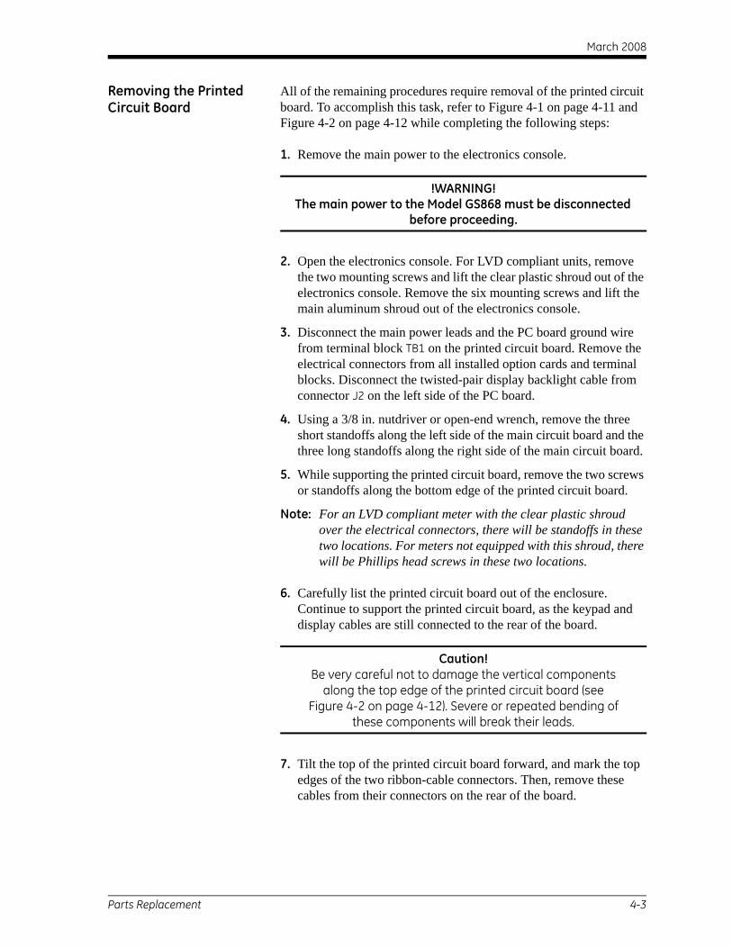
Removing the Printed Circuit Board
All of the remaining procedures require removal of the printed circuit board. To accomplish this task, refer to Figure 4-1 on page 4-11 and Figure 4-2 on page 4-12 while completing the following steps:
1. Remove the main power to the electronics console.
!WARNING!The main power to the Model GS868 must be disconnected
before proceeding.
2. Open the electronics console. For LVD compliant units, remove the two mounting screws and lift the clear plastic shroud out of the electronics console. Remove the six mounting screws and lift the main aluminum shroud out of the electronics console.
3. Disconnect the main power leads and the PC board ground wire from terminal block TB1 on the printed circuit board. Remove the electrical connectors from all installed option cards and terminal blocks. Disconnect the twisted-pair display backlight cable from connector J2 on the left side of the PC board.
4. Using a 3/8 in. nutdriver or open-end wrench, remove the three short standoffs along the left side of the main circuit board and the three long standoffs along the right side of the main circuit board.
5. While supporting the printed circuit board, remove the two screws or standoffs along the bottom edge of the printed circuit board.
Note: For an LVD compliant meter with the clear plastic shroud over the electrical connectors, there will be standoffs in these two locations. For meters not equipped with this shroud, there will be Phillips head screws in these two locations.
6. Carefully list the printed circuit board out of the enclosure. Continue to support the printed circuit board, as the keypad and display cables are still connected to the rear of the board.
Caution!Be very careful not to damage the vertical components
along the top edge of the printed circuit board (see Figure 4-2 on page 4-12). Severe or repeated bending of
these components will break their leads.
7. Tilt the top of the printed circuit board forward, and mark the top edges of the two ribbon-cable connectors. Then, remove these cables from their connectors on the rear of the board.
Parts Replacement 4-3

March 2008
Removing the Printed Circuit Board (cont.)
8. The printed circuit board is now free and may be removed to a clean work area.
If the printed circuit board is being replaced, proceed to the section on Installing the Printed Circuit Board (page 4-7) now. Otherwise, refer to the appropriate section for instructions on Installing an Option Card (page 4-5), Replacing the EPROM (below) or Replacing the LCD Display (page 4-6).
Replacing the EPROM The Model GS868’s User Program is stored on an erasable programmable read only memory (EPROM) chip. The EPROM, which is designated as component U4, is located in the top left corner of the rear of the printed circuit board. See Figure 4-2 on page 4-12 for a rear view of the printed circuit board.
EPROM replacement may be required to replace a defective chip or to upgrade to a newer software version. To replace the EPROM, complete the following steps:
1. Remove the printed circuit board, as described in a previous section of this chapter.
2. Place the printed circuit board face down on a clean, flat surface. Locate the EPROM socket in the top left corner of the board.
3. Using a chip puller, remove the EPROM from its socket. If a chip puller is unavailable, a straightened paper clip may be used in the notches at the upper right and lower left corners of the socket. Gently pry the EPROM up, a little at a time, at each notch until it comes free.
Caution!The EPROM is easily damaged by static electricity. Before handling the new chip, touch a grounded metal object to
discharge any built-up static electricity and avoid touching the leads on the side of the chip.
4. Make sure that the beveled corner on the new EPROM is aligned with the beveled corner of the socket and place the EPROM into the socket.
5. By applying equal pressure on all four corners, gently press the EPROM into the socket until it is fully seated. Do not strike the EPROM or apply excessive force during this procedure.
To complete the EPROM replacement, proceed to Installing the Printed Circuit Board on page 4-7.
4-4 Parts Replacement

March 2008
Installing an Option Card The Model GS868 flowmeter can accommodate up to six option cards. The option cards are installed into sockets on the rear of the printed circuit board, and they are held in place with a metal bracket. A single metal bracket is used to secure all the installed option cards.
Note: If the Model GS868 presently has no option cards installed, be sure to purchase the metal mounting bracket along with the first option card.
To install an option card, refer to Figure 4-2 on page 4-12 and complete the following steps:
1. Remove the printed circuit board, as described in a previous section of this chapter.
2. If one or more option cards are already installed, remove the four fasteners that secure the metal bracket to the printed circuit board. Lift the metal bracket straight up and away from the printed circuit board.
Note: The fasteners may be either plastic snap rivets or metal hardware (in some older meters). In either case, they may be discarded, as new plastic snap rivets will be provided.
3. There are six 32-pin option card sockets (J41–J46) on the rear of the printed circuit board. To install an option card, insert its 32-pin connector into any available option card socket and gently press the card into place. Make sure that the pins in the connector are straight and properly aligned with the socket and that the connector is positioned on the right side of the option card.
Caution!Do not force the option card into the socket. If the card
does not enter the socket easily, check for and straighten any bent pins in the connector and try again.
4. Repeat step 3 to install any additional option cards.
5. Place the metal bracket over the option cards, making sure that all option cards are aligned with the plastic card guides in the bracket. Secure the metal bracket to the printed circuit board with the plastic snap rivets provided. Refer to the installed assembly in Figure 4-1 on page 4-11.
To complete the option card installation, proceed to Installing the Printed Circuit Board on page 4-7.
Parts Replacement 4-5

March 2008
Replacing the LCD Display
The Model GS868’s measurements are displayed on a a two-pane LCD graphic display panel. The LCD display normally provides years of dependable service, but it is easily field-replaceable when necessary. To replace the LCD display, see Figure 4-1 on page 4-11 for the component locations, and complete the following steps:
1. Remove the printed circuit board, as described in a previous section of this chapter.
2. Using a 3/16 in. nutdriver, remove the four nut/washer sets that secure the display shroud to the inside of the console cover. Lift the display shroud off its mounting studs.
3. Using a 1/4” nutdriver, remove the four standoffs that secure the LCD display assembly to the console cover. Lift the LCD display assembly off its mounting studs.
4. Place the new LCD display assembly over the mounting studs on the console cover and fasten it in place with the four standoffs. Make sure that the LCD display assembly is oriented as shown in Figure 4-2 on page 4-12.
Caution!Do not overtighten the standoffs or the display assembly
may be damaged.
5. Position the LCD display cables between the two right side mounting studs, and install the display shroud over the mounting studs. The top and bottom edges of the shroud are bent at a 90° angle to the main surface, and these edges must face inwards toward the display assembly.
Note: One edge of the display shroud is covered with a piece of black electrical tape. This side of the shroud should be on the right, to protect the cables against abrasion.
6. Fasten the display shroud to the console cover with the four sets of nuts/washers.
Caution!Do not overtighten the nuts or damage to the mounting
threads may occur.
To complete the LCD Display replacement, proceed to Installing the Printed Circuit Board on page 4-7.
4-6 Parts Replacement

March 2008
Installing the Printed Circuit Board
Whether the printed circuit board was removed for replacement or for one of the other procedures discussed in this chapter, reinstallation of the printed circuit board is the final step in the process. Refer to Figure 4-1 on page 4-11 and complete the following steps:
1. Position the printed circuit board within the electronics console with the top edge tilted forward. Insert the display ribbon cable and keypad ribbon cable connectors into their sockets on the rear of the printed circuit board. See Figure 4-1 on page 4-11 and Figure 4-2 on page 4-12 to identify the cables and sockets. Note that the keypad cable connects to the upper socket and the display cable connects to the lower socket.
IMPORTANT: The ribbon cables must be installed with the edges that were marked during removal oriented toward the top of the printed circuit board.
2. Carefully position the printed circuit board up against the eight standoffs in the enclosure. Do not damage the transformers and any installed option cards as they are maneuvered between the standoffs.
Caution!During this procedure, be very careful not to damage the
upright components along the top edge of the printed circuit board (see Figure 4-2 on page 4-12). Severe or
repeated bending of these components will break their leads.
3. Loosely install the three long standoffs on the right side of the printed circuit board and the two standoffs (or screws) on the bottom edge of the printed circuit board. Then, install only the top and bottom short standoffs on the left side of the printed circuit board.
4. Insert the free end of the green grounding strap between the printed circuit board and the middle standoff beneath the left side of the board. Making sure to capture the grounding strap lug between the printed circuit board and the standoff beneath it, install the remaining short standoff on the left side of the printed circuit board. Securely tighten all eight standoffs and/or screws.
IMPORTANT: Correctly installing the grounding strap may require some patience, but resist the temptation to place the grounding strap on top of the printed circuit board.
Parts Replacement 4-7

March 2008
Installing the Printed Circuit Board (cont.)
5. Connect the twisted-pair backlight cable to socket J2 on the left edge of the printed circuit board. This plug is polarized so that it can only be installed in the proper orientation, with the black wire above the red wire.
6. Check for and remove any loose hardware that may have fallen into the electronics console during the maintenance procedure.
7. Place the main shroud over the six upper standoffs on the printed circuit board. Making sure that the shroud is oriented with the wiring diagram label upright, fasten the shroud to the standoffs with the six sets of screws and washers.
8. Reconnect the power line wires and the PC board ground wire to terminal block TB1 on the printed circuit board. Plug all other electrical connectors into the appropriate sockets on the printed circuit board and option cards. See Chapter 1, Installation, of the Startup Guide for instructions on proper wiring of the Model GS868.
Note: For an LVD compliant meter with the clear plastic shroud over the electrical connectors, there will be standoffs in the two mounting locations along the bottom edge of the printed circuit board. For meters not equipped with this shroud, there will be Phillips head screws in these two locations.
9. For LVD compliant units, position the clear plastic LVD shroud over the electrical connections so that the two holes in the shroud align with the standoffs on the printed circuit board. Secure the shroud to the standoffs with the two sets of screws and washers.
10. After carefully checking for and removing any loose hardware in the enclosure, close the electronics console and reconnect the main power to the Model GS868.
Note: For compliance with the European Union’s Low Voltage Directive (73/23/EEC), this unit requires an external power disconnect device such as a switch or circuit breaker. The disconnect device must be marked as such, clearly visible, directly accessible, and located within 1.8 m (6 ft) of the Model GS868.
Before taking measurements with the Model GS868, refer to Chapter 2, Initial Setup, of the Startup Guide and Chapter 1, Calibration, of the Service Manual for instructions on properly setting up the meter for accurate flow rate measurements.
Note: Be sure to enter a complete and detailed account of any parts replacement performed on the Model GS868 in Appendix A, Service Record.
4-8 Parts Replacement

March 2008
Spare Parts All of the necessary components to upgrade or repair the Model GS868 flowmeter are readily available from the factory. As a convenient reference, some of the more common spare parts are listed in Table 4-2 below.
To purchase the parts listed in Table 4-2 above or any items not listed in the table, contact the factory for assistance. To make sure the proper components are obtained, be sure to specify the serial number of the Model GS868 at the time of purchase.
Table 4-2: Spare Parts List
Part Number Description703-1127-02 Option Card - Alarms, Hermetically Sealed703-1127-03 Option Card - Alarms, General Purpose703-1145-02 Option Card - Analog Inputs703-1126-02 Option Card - Analog Outputs703-1145-03 Option Card - RTD Inputs703-1144-02 Option Card - Totalizer/Frequency Outputs
421-703 Card Cage (Metal Bracket)417-027 Card Guide, Nylon
703-1247 Printed Circuit Board705-671 LCD Display Assembly147-744 EPROM421-700 Conduit Plate, 1/2”421-701 Conduit Plate, 3/4”421-702 Conduit Plate, Blank421-946 LVD Plastic Shroud421-686 Main Aluminum Shroud442-484 Label, Wiring Diagram
Parts Replacement 4-9

March 2008
4-11
racket
Main Shroud
Option Card Socket
Metal Bracket
Fasteners
Option Card
Standoffs (typ.)
LVD Shroud
Screw8 places
PC Board
Standoffs
LCD Display
Display Shroud
Nuts & Washers
Side View
D Shroud
Figu
re 4
-1: S
tand
ard
Mod
el G
S868
- El
ectr
onic
s Co
nsol
e As
sem
bly
Parts Replacement
WARNING
ALARMS ANALOG OUT ANALOG IN TOTL/FREQ RTD IN
CHAN 2SIG N
TR
NTR
GSI
RS 232
T TTR
TS NR
XXC D R
UPDNANALOG OUT
DNCHAN 1
GIS
GN N
SI
RT
RT
UP
XDCRS
B− ++ −
A
TWIND
RWIND
RCV
GATE
DRTN
Nuts & Washers4 places
Display Shroud
Display Cable
Keypad Cable
Backlight Cable
Mounting Screw 8 places Main Shroud
Option Cards
Fuse Holder Cap
Card Guide Metal B
Bottom View
Front View
LV
Fuse HolderPowerConnector
PC BoardGround Wire
Internal GroundConnection
CoverGround Wire
G N/L2 L1 ACG – + DC

March 2008
4-12
ndoffes
Metal Bracket Option Card Connectors
Fasteners (typ.)
Display Connector (J52)
Keypad Connector (J50)
EPROM (U4)
BeveledCorner
Rear View
Figu
re 4
-2: S
tand
ard
Mod
el G
S868
- Pr
inte
d C
ircu
it Bo
ard
Asse
mbl
y
Parts Replacement
1
14
REDBLACK
Display Cable
LCD Display
Backlight Cable
Keypad Cable
J2 Connector
PC Board Ground Wire Screws or Standoffs
Short Standoff 3 places
Vertical Components
Long Sta 3 plac
Front View
G N/L2 L1 ACG – + DC

Appendix A

Service Record
Introduction. . . . . . . . . . . . . . . . . . . . . . . . . . . . . . . . . . . . . . . . . . . . . . . . . . . . A-1
Data Entry . . . . . . . . . . . . . . . . . . . . . . . . . . . . . . . . . . . . . . . . . . . . . . . . . . . . . A-1
Diagnostic Parameters . . . . . . . . . . . . . . . . . . . . . . . . . . . . . . . . . . . . . . . . . . A-3

March 2008
Introduction Whenever any service procedure is performed on the Model GS868 flowmeter, the details of the service should be recorded in this appendix. An accurate service history of the meter can prove very helpful in troubleshooting any future problems.
Data Entry Record complete and detailed service data for the Model GS868 in Table A-1 below. Make additional copies of the table as needed.
Table A-1: Service Record
Date Description of Service Performed By
Service Record A-1

March 2008
Table A-1: Service Record (Continued)
Date Description of Service Performed By
A-2 Service Record

March 2008
Diagnostic Parameters After a successful initial installation of the Model GS868 and whenever any system malfunction is noticed, the values for the diagnostic parameters should be entered in Table A-2 below.
Table A-2: Diagnostic Parameters
Parameter Initial Current Parameter Initial CurrentSS up MwSS do z
SNDSP AcVOLTup StVOL
Tdown Tu S*DELTA Td S*
PEAK% DT S*Qup Tu M*
Qdown Td M*AMPup DT M*AMPdn VinstCNTup TsatCNTdn TsuprP#up RhoP#dn KelvnTEMP kPaPRES QUAL
* These parameters are available only in the Skan/Measure mode.
Service Record A-3

Appendix B

Optional Enclosures
Introduction. . . . . . . . . . . . . . . . . . . . . . . . . . . . . . . . . . . . . . . . . . . . . . . . . . . . B-1
Rack Mount Enclosure. . . . . . . . . . . . . . . . . . . . . . . . . . . . . . . . . . . . . . . . . . . B-1
Rack Mount Fuse Replacement . . . . . . . . . . . . . . . . . . . . . . . . . . . . . . . . . . . B-2
Rack Mount Option Card Installation . . . . . . . . . . . . . . . . . . . . . . . . . . . . . B-3
Rack Mount EPROM Replacement . . . . . . . . . . . . . . . . . . . . . . . . . . . . . . . . B-5
Rack Mount LCD Display Replacement . . . . . . . . . . . . . . . . . . . . . . . . . . . . B-6
Rack Mount Printed Circuit Board Replacement. . . . . . . . . . . . . . . . . . . . B-8

March 2008
Introduction The Model GS868 is available in optional enclosure types, each of which has been designed to permit easy on-site upgrades and parts replacement. See the foldout drawings at the end of this appendix for details of the applicable GS868 electronics console assembly. The instructions in this appendix, along with a few common tools, are all that is required to perform the following tasks:
• fuse replacement
• option card installation
• EPROM replacement
• LCD display replacement
• printed circuit board (PCB) replacement
IMPORTANT: For meters supplied in the standard Type-4X enclosure, see Chapter 4, Parts Replacement, for instructions specific to that unit.
!WARNING!Prior to performing any maintenance procedures,
disconnect the main power from the unit.
Note: For compliance with the European Union’s Low Voltage Directive (73/23/EEC), this unit requires an external power disconnect device such as a switch or circuit breaker. The disconnect device must be marked as such, clearly visible, directly accessible, and located within 1.8 m (6 ft) of the Model GS868.
Rack Mount Enclosure Refer to Figure B-1 on page B-11 and Figure B-2 on page B-12 for the location of the relevant components, while completing the following procedures. If the top panel of the meter is accessible, service may be performed without removing the meter from the rack. Otherwise, disconnect all rear panel electrical connections and remove the meter from the rack before proceeding.
IMPORTANT: Keep a detailed record of all service procedures in Appendix A, Service Record. This record may prove very helpful in diagnosing any future problems.
Optional Enclosures B-1

March 2008
Rack Mount Fuse Replacement
If it has been determined that the fuse in the Model GS868 requires replacement, refer to Figure B-1 on page B-11 and Figure B-2 on page B-12, and complete the following steps:
1. On the rear panel of the meter, set the power switch to the OFF position and pull the power cord out of its receptacle.
!WARNING!The main power to the Model GS868 must be disconnected
before proceeding.
2. Locate the black plastic fuse cover on the back panel at the bottom of the power cord receptacle and pull it straight out.
3. Replace the defective fuse with a new one of the same rating and type. Use only 5 x 20 mm Slo-Blo fuses, having a rating as indicated in Table B-1 below and on the rear panel label.
4. Reinstall the black plastic fuse cover and insert the power cord back into the receptacle. Then, position the power switch in the ON position.
The Model GS868 flowmeter may now be placed back into service. Reconnect the main power and resume taking measurements.
Note: Be sure to record the fuse replacement in Appendix A, Service Record.
Table B-1: Line Voltages & Fuse Ratings
Line Voltage Fuse Rating100-120 VAC 1.0 A, Slo-Blo220-240 VAC 0.5 A, Slo-Blo
12-28 VDC 3.0 A, Slo-Blo
B-2 Optional Enclosures

March 2008
Rack Mount Option Card Installation
The Model GS868 flowmeter can accommodate up to six option cards in a manner similar to that used in a PC. The option cards are installed into sockets on the printed circuit board, and they are held in place with a metal bracket. A single metal bracket is used to secure all the installed option cards.
Note: If the Model GS868 presently has no option cards installed, be sure to purchase the metal mounting bracket along with the first option card.
Refer to Figure B-2 on page B-12 and complete the following steps:
1. After disconnecting the main power to the meter, remove the top panel from the enclosure by removing the four screws indicated.
!WARNING!The main power to the Model GS868 must be disconnected
before proceeding.
2. If one or more option cards are already installed, remove the four fasteners that secure the metal bracket to the printed circuit board. Lift the metal bracket straight up and away from the printed circuit board.
Note: The fasteners may be either plastic snap rivets or metal hardware (in some older meters). In either case, they may be discarded, as new plastic snap rivets will be provided.
3. There are six 32-pin option card sockets (J41–J46) on the rear of the printed circuit board. By removing the screw on the rear panel, remove the appropriate option slot cover to make room for the external connector on the new option card.
4. To install the option card, insert its 32-pin connector into the chosen option card socket and gently press the card into place. Make sure that the pins in the connector are straight and properly aligned with the socket and that the option card is oriented with its external connector positioned in the opening on the rear panel.
Caution!Do not force the option card into the socket. If the card
does not enter the socket easily, check for and straighten any bent pins in the connector and try again.
5. Repeat steps 3 and 4 to install any additional option cards.
Optional Enclosures B-3

March 2008
Rack Mount Option Card Installation (cont.)
6. Place the metal bracket over the option cards, making sure that all installed option cards are inserted into the plastic card guides in the bracket. The bracket must be oriented so that the six card guides are directly above the six sockets on the printed circuit board (do not install the bracket rotated 180° out of position). Secure the metal bracket to the printed circuit board with the four plastic snap rivets provided.
7. After checking for any loose hardware that may have fallen into the enclosure, reinstall the top panel on the meter and secure the panel in place with the four screws previously removed.
The Model GS868 flowmeter may now be placed back into service. Reconnect the main power and refer to Appendix C, Optional Enclosures, of the Startup Guide for instructions on wiring the new option card(s).
Note: Be sure to record the option card installation in Appendix A, Service Record.
B-4 Optional Enclosures

March 2008
Rack Mount EPROM Replacement
The Model GS868’s User Program is stored on an erasable programmable read only memory (EPROM) chip. The EPROM, which is designated as component U4, is located on the corner of the printed circuit board just behind the keypad on the front panel.
EPROM replacement may be required to replace a defective chip or to upgrade to a newer software version. To replace the EPROM, refer to Figure B-2 on page B-12 and complete the following steps:
1. After disconnecting the main power to the meter, remove the top panel from the enclosure by removing the four screws indicated.
!WARNING!The main power to the Model GS868 must be disconnected
before proceeding.
2. Using a chip puller, remove the EPROM from its socket. If a chip puller is unavailable, a straightened paper clip may be used in the notches at opposite corners of the socket. Gently pry the EPROM up, a little at a time, at each notch until it comes free.
Caution!The EPROM is easily damaged by static electricity. Before handling the new chip, touch a grounded metal object to
discharge any built-up static electricity and avoid touching the leads on the side of the chip.
3. Make sure that the beveled corner on the new EPROM is aligned with the beveled corner of the socket and place the EPROM into the socket.
4. By applying equal pressure on all four corners, gently press the EPROM into the socket until it is fully seated. Do not strike the EPROM or apply excessive force during this procedure.
5. After checking for any loose hardware that may have fallen into the enclosure, reinstall the top panel on the meter and secure the panel in place with the four screws previously removed.
The Model GS868 flowmeter may now be placed back into service. Reconnect the main power and resume taking measurements.
Note: Be sure to record the EPROM replacement in Appendix A, Service Record.
Optional Enclosures B-5

March 2008
Rack Mount LCD Display Replacement
The Model GS868 measurements are displayed on a a two-pane LCD graphic display panel. The LCD display normally provides years of dependable service, but it is field-replaceable when necessary.
To replace the LCD display, refer to Figure B-2 on page B-12 and complete the following steps:
1. After disconnecting the main power to the meter, remove the top panel from the enclosure by removing the four screws indicated.
!WARNING!The main power to the Model GS868 must be disconnected
before proceeding.
2. Using a 3/16 in. nutdriver, remove the four nut/washer sets that secure the display shroud to the inside of the front panel. Pull the display shroud off its mounting studs.
3. Using a 1/4” nutdriver, remove the four standoffs that secure the LCD display assembly to the front panel. Pull the LCD display assembly off its mounting studs.
4. Place the new display in the enclosure and replace the circuit board connections of the data and power cables of the old display with those of the new display. Be sure to orient the new cables in the same way as the old ones, when making the connections to the printed circuit board. Remove and discard the old LCD display.
5. Place the new LCD display assembly over the mounting studs on the front panel and fasten it in place with the four standoffs. Make sure that the LCD display assembly is oriented with the cables pointing toward the left side (away from the keypad) of the meter.
Caution!Do not overtighten the standoffs or the display assembly
may be damaged.
6. Position the LCD display cables between the two mounting studs, and install the display shroud over the mounting studs. The top and bottom edges of the shroud are bent at a 90° angle to the main surface, and these edges must face inwards toward the display assembly.
Note: One edge of the display shroud is covered with a piece of black electrical tape. This side of the shroud should be over the cables to protect them against abrasion.
B-6 Optional Enclosures

March 2008
Rack Mount LCD Display Replacement (cont.)
7. Fasten the display shroud to the front panel with the four sets of nuts/washers.
Caution!Do not overtighten the nuts or damage to the mounting
threads may occur.
8. After checking for any loose hardware that may have fallen into the enclosure, reinstall the top panel on the meter and secure the panel in place with the four screws previously removed.
The Model GS868 flowmeter may now be placed back into service. Reconnect the main power and resume taking measurements.
Note: Be sure to record the LCD Display replacement in Appendix A, Service Record.
Optional Enclosures B-7

March 2008
Rack Mount Printed Circuit Board Replacement
If troubleshooting procedures have indicated a defective printed circuit board, follow the instructions in this section to replace the defective board with a new one.
Circuit Board Removal Refer to Figure B-2 on page B-12 and complete the following steps:
1. After disconnecting the main power to the meter, remove the top panel from the enclosure by removing the four screws indicated.
!WARNING!The main power to the Model GS868 must be disconnected
before proceeding.
2. Disconnect all external option card connectors at the rear panel of the meter. Then, remove all installed option cards from the printed circuit board, as described earlier in this chapter.
3. Disconnect the main POWER LEADS from the screw terminals at the rear of the printed circuit board. Make a sketch of the terminal block and the locations of the black, white and green power leads to assist in reinstallation on the new circuit board.
4. Remove the RS232, ANALOG OUT and TRANSDUCER connectors from the printed circuit board. Use a marker to identify pin #1 on the right side (keypad side) of these connectors.
Note: These connectors should be pulled straight up and off the printed circuit board. DO NOT remove the leads from the screw terminals.
5. Remove the flat KEYPAD CABLE connector from terminal J50 near the front of the printed circuit board. Mark pin #1 of the cable connector, which is located nearer the rear of the enclosure.
6. Disconnect the twisted-pair DISPLAY BACKLIGHT cable from connector J2 beneath the left side of the printed circuit board. Although this connector is polarized, it will help to note that the red wire is closer to the rear of the enclosure.
7. Remove the flat LCD DISPLAY CABLE connector from terminal J52 near the option card sockets. Mark pin #1 of the cable connector, which is located nearer the front of the enclosure.
8. Using a slotted screwdriver, remove the three mounting screws along each side of the printed circuit board. Carefully lift the printed circuit board out of the enclosure.
Proceed to the next section for instructions on installing the new printed circuit board.
B-8 Optional Enclosures

March 2008
Circuit Board Installation Refer to Figure B-2 on page B-12 and complete the following steps:
1. Position the new printed circuit board within the electronics console so that it rests on the six standoffs in the base of the enclosure and the option card sockets are located near the rear of the enclosure. Secure the circuit board in place with the six screws previously removed.
2. Connect the flat LCD DISPLAY CABLE connector to terminal J52 near the option card sockets. Make sure the marked pin #1 side of the cable connector is located nearer the front of the enclosure.
3. Connect the twisted-pair DISPLAY BACKLIGHT cable to connector J2 beneath the left side of the printed circuit board. This connector is polarized and can only be installed with the red wire closer to the rear of the enclosure.
4. Connect the flat KEYPAD CABLE connector to terminal J50 near the front of the printed circuit board. Make sure the marked pin #1 side of the cable connector is located nearer the rear of the enclosure.
5. Install the RS232, ANALOG OUT and TRANSDUCER connectors onto the printed circuit board at the locations indicated in Figure B-2 on page B-12. Make sure the marked pin #1 sides of the connectors face the right side (keypad side) of the enclosure.
Note: If any leads have come loose from the screw terminals on these connectors, refer to Appendix C, Optional Enclosures, of the Startup Guide for wiring instructions.
6. Reconnect the main POWER LEADS to the screw terminals at the rear of the printed circuit board. When properly installed, the lead colors should be green, white and black, from left to right (as viewed from the front of the enclosure).
7. Reinstall all option cards, as described earlier in this chapter. Insert all external option card connectors at the rear panel of the meter.
8. After checking for any loose hardware that may have fallen into the enclosure, reinstall the top panel on the meter and secure the panel in place with the four screws previously removed.
The Model GS868 flowmeter may now be placed back into service. Reconnect the main power and refer to Chapter 2, Initial Setup, of the Startup Guide and Chapter 1, Calibration, of this Service Manual for instructions on properly setting up the meter for accurate flow rate measurements.
Note: Be sure to record the printed circuit board replacement in Appendix A, Service Record.
Optional Enclosures B-9

March 2008
B-11
2.25 (57) 5.22(133)
11.82(300) 13.13
(333)
Figu
re B
-1: M
odel
GS8
68 R
ack
Mou
nt E
nclo
sure
Dim
ensi
ons
- (re
f. dw
g #
712-
1078
)
Optional Enclosures
GS868
19.00 (483)
18.25 (464)
11.37(289)
4.19 (106)
15.70 (399)3.31 (84)
14.83 (377)
16.99 (432)
A / OUT ALARMSA / INRTD IN
Fuse

March 2008
B-12
Nut & Washers (typ.)
Standoff (typ.)
alog Output Connector
CH1 Transducer Connector
CH2 Transducer Connector
EPROM (U4)
PCB Mounting Screw (typ.)
Option Card Bracket
Card Slot Cover
Snap Rivets (typ.)
Top Panel Mounting Hole4 places
Figu
re B
-2: M
odel
GS8
68 R
ack
Mou
nt C
onso
le A
ssem
bly
- (re
f. dw
g #
705-
849)
Optional Enclosures
Pin 1
Display ShroudLCD DisplayKeypad Cable
Backlight Cable
Black Lead
Red Lead
Display Cable
An
Printed Circuit Board
Option Card Socket(typ.)
RS232 Connector
Ground Lead (Green)
Option
Beveled Corner
Power Terminal Block
Line Lead (Black)
Neutral Lead (White)
Fuse

March 2008
Index
AAcceleration Error - E6 . . . . . . . . . . . . . . . . . 2-3Alarms Option Card, Testing . . . . . . . . . . . . 1-11Amplitude Error - E5 . . . . . . . . . . . . . . . . . . . 2-3Analog Inputs Option Card, Calibrating . . . . 1-6Analog Output Error - E7. . . . . . . . . . . . . . . . 2-3Analog Outputs (Slot 0)
As Calibrated Current Source . . . . . . . . . . 1-6Calibrating . . . . . . . . . . . . . . . . . . . . . . . . . 1-2Linearity . . . . . . . . . . . . . . . . . . . . . . . . . . . 1-2Resolution . . . . . . . . . . . . . . . . . . . . . . . . . 1-2
Analog Outputs Option CardCalibrating . . . . . . . . . . . . . . . . . . . . . . . . . 1-2Linearity . . . . . . . . . . . . . . . . . . . . . . . . . . . 1-2Resolution . . . . . . . . . . . . . . . . . . . . . . . . . 1-2
BBracket, Option Card . . . . . . . . . . . . . . . . . . . 4-5
CCable
Backlight . . . . . . . . . . . . . . . . . . . . . . 4-3, 4-8Display . . . . . . . . . . . . . . . . . . . . . . . . 4-3, 4-6Keypad . . . . . . . . . . . . . . . . . . . . . . . . . . . . 4-3
CalibratingSee Parameter Name
Calibration Menu, Entering . . . . . . . . . . . . . . 1-1Circuit Board
See Printed Circuit BoardContamination, Gas . . . . . . . . . . . . . . . . . . . . 3-4Corrosion, Transducers . . . . . . . . . . . . . . . . . 3-6
DDiagnostic Parameters
Initial Values . . . . . . . . . . . . . . . . . . . . . . . .3-4Table . . . . . . . . . . . . . . . . . . . . . . . . . . . . . .3-2Table of Values . . . . . . . . . . . . . . . . . . . . . A-3
Diagnostics MenuEntering. . . . . . . . . . . . . . . . . . . . . . . . . . . .3-1Exiting. . . . . . . . . . . . . . . . . . . . . . . . . . . . .3-4
DisplayCable . . . . . . . . . . . . . . . . . . . . . . . . . . . . . .4-3LCD. . . . . . . . . . . . . . . . . . . . . . . . . . . . . . .4-6Replacing . . . . . . . . . . . . . . . . . . . . . . . . . .4-6
Display Screen . . . . . . . . . . . . . . . . . . . . . . . .2-1
EEPROM
Replacing . . . . . . . . . . . . . . . . . . . . . . . . . .4-4User Program . . . . . . . . . . . . . . . . . . . . . . .4-4
Error Codes . . . . . . . . . . . . . . . .2-2, 2-3, 2-4, 2-5Error Message, Display Screen. . . . . . . . . . . .2-1Expansion Slots. . . . . . . . . . . . . . . . . . . . . . . .1-1
FFlowcell Problems
Gas . . . . . . . . . . . . . . . . . . . . . . . . . . . . . . .3-4Pipe . . . . . . . . . . . . . . . . . . . . . . . . . . . . . . .3-5
FuseHolder . . . . . . . . . . . . . . . . . . . . . . . . . . . . .4-2Rating . . . . . . . . . . . . . . . . . . . . . . . . . . . . .4-2Replacing . . . . . . . . . . . . . . . . . . . . . . . . . .4-2Size . . . . . . . . . . . . . . . . . . . . . . . . . . . . . . .4-2Type. . . . . . . . . . . . . . . . . . . . . . . . . . . . . . .4-2
GGas
Contamination. . . . . . . . . . . . . . . . . . . . . . .3-4Physical Requirements . . . . . . . . . . . . . . . .3-4Problems . . . . . . . . . . . . . . . . . . . . . . . . . . .3-4Soundspeed . . . . . . . . . . . . . . . . . . . . . . . . .3-5
Grounding Strap . . . . . . . . . . . . . . . . . . . . . . .4-7Guides, Option Card . . . . . . . . . . . . . . . . . . . .4-5
Index 1

March 2008
Index (cont.)
KKeypad, Cable. . . . . . . . . . . . . . . . . . . . . . . . . 4-3
LLCD Display. . . . . . . . . . . . . . . . . . . . . . . . . . 4-6Leaks, Transducers . . . . . . . . . . . . . . . . . . . . . 3-6Low Pressure Error - E12 . . . . . . . . . . . . . . . . 2-4Low Signal Error - E1. . . . . . . . . . . . . . . . . . . 2-2LVD Statement . . . . . . . . . . . . . . . . . . . . . . . . 4-1
NNo Error - E0 . . . . . . . . . . . . . . . . . . . . . . . . . 2-2Numer Option
for RTD Option Card . . . . . . . . . . . . . . . . 1-10
OOption Card
Analog Outputs . . . . . . . . . . . . . . . . . . . . . . 1-2Bracket . . . . . . . . . . . . . . . . . . . . . . . . . . . . 4-5Expansion Slots . . . . . . . . . . . . . . . . . . . . . 1-1Guides . . . . . . . . . . . . . . . . . . . . . . . . . . . . . 4-5Installing . . . . . . . . . . . . . . . . . . . . . . . . . . . 4-5Sockets . . . . . . . . . . . . . . . . . . . . . . . . . . . . 4-5
Over Range Error - E13 . . . . . . . . . . . . . . . . . 2-5
PPipe
Measurements . . . . . . . . . . . . . . . . . . . . . . . 3-5Problems . . . . . . . . . . . . . . . . . . . . . . . . . . . 3-5
Pressure Input Error - E9 . . . . . . . . . . . . . . . . 2-4Printed Circuit Board
EPROM. . . . . . . . . . . . . . . . . . . . . . . . . . . . 4-4Replacing . . . . . . . . . . . . . . . . . . . . . . . . . . 4-3
PROBE Optionfor RTD Option Card . . . . . . . . . . . . . . . . . 1-9
Problems, Transducers . . . . . . . . . . . . . . . . . . 3-6
RReboot, Automatic . . . . . . . . . . . . . . . . . . . . . 1-1Replacing
See Part Name
SScreen Messages, Table. . . . . . . . . . . . . . . . . 2-6Service Record. . . . . . . . . . . . . . . . . . . . . . . . A-1Shroud
Aluminum . . . . . . . . . . . . . . . . . . . . . .4-1, 4-8LCD Display . . . . . . . . . . . . . . . . . . . . . . . 4-6LVD . . . . . . . . . . . . . . . . . . . . . . . . . . . . . . 4-8Plastic . . . . . . . . . . . . . . . . . . . . . . . . . . . . 4-8
Signal Quality Error - E4. . . . . . . . . . . . . . . . 2-3Sockets, Option Card. . . . . . . . . . . . . . . . . . . 4-5Soundspeed
Error - E2 . . . . . . . . . . . . . . . . . . . . . . . . . . 2-2Gas . . . . . . . . . . . . . . . . . . . . . . . . . . . . . . . 3-5
Spare Parts List . . . . . . . . . . . . . . . . . . . . . . . 4-9Special Input Error - E10. . . . . . . . . . . . . . . . 2-4Super Saturated Error - E11. . . . . . . . . . . . . . 2-4
TTemperature Input Error - E8 . . . . . . . . . . . . 2-4Totalizer/Frequency Option Card, Testing . 1-13Totals Overflow Error - E14 . . . . . . . . . . . . . 2-5Transducers
Corrosion . . . . . . . . . . . . . . . . . . . . . . . . . . 3-6Internal Damage . . . . . . . . . . . . . . . . . . . . 3-6Leaks . . . . . . . . . . . . . . . . . . . . . . . . . . . . . 3-6Physical Damage . . . . . . . . . . . . . . . . . . . . 3-6Placement . . . . . . . . . . . . . . . . . . . . . . . . . 3-5Problems . . . . . . . . . . . . . . . . . . . . . . . . . . 3-6Replacement . . . . . . . . . . . . . . . . . . . . . . . 3-6
UUser Program
EPROM . . . . . . . . . . . . . . . . . . . . . . . . . . . 4-4Upgrading . . . . . . . . . . . . . . . . . . . . . . . . . 4-4
VVelocity Range Error - E3 . . . . . . . . . . . . . . . 2-2
2 Index

GE Sensing
DECLARATIONOF
CONFORMITY
CERT-DOC-H4 August 2004
TÜV ESSENISO 9001
U.S.
TÜV
We, Panametrics Limited Shannon Industrial Estate
Shannon, County Clare Ireland
declare under our sole responsibility that the
DF868 Liquid Ultrasonic FlowmeterGF868 Flare Gas Ultrasonic Flowmeter
GM868 Multi-Purpose Gas Ultrasonic FlowmeterGN868 Natural Gas Ultrasonic FlowmeterGS868 Steam Mass Ultrasonic Flowmeter
to which this declaration relates, are in conformity with the following standards:
• EN 61326:1998, Class A, Annex A, Continuous Unmonitored Operation
• EN 61010-1:1993 + A2:1995, Overvoltage Category II, Pollution Degree 2
following the provisions of the 89/336/EEC EMC Directive and the 73/23/EEC Low Voltage Directive.
The units listed above and any transducers supplied with them (spoolpieces are addressed under a separate declaration of conformity) do not bear CE marking for the Pressure Equipment Directive, as they are supplied in accordance with Article 3, Section 3 (sound engineering practices and codes of good workmanship) of the Pressure Equipment Directive 97/23/EC for DN<25.
Shannon - June 1, 2002Mr. James Gibson
GENERAL MANAGER

GESensing
DECLARATIONDE
CONFORMITE
CERT-DOC-H4 August 2004
TÜV ESSENISO 9001
U.S.
TÜV
Nous, Panametrics Limited Shannon Industrial Estate
Shannon, County Clare Ireland
déclarons sous notre propre responsabilité que les
DF868 Liquid Ultrasonic FlowmeterGF868 Flare Gas Ultrasonic Flowmeter
GM868 Multi-Purpose Gas Ultrasonic FlowmeterGN868 Natural Gas Ultrasonic FlowmeterGS868 Steam Mass Ultrasonic Flowmeter
rélatif á cette déclaration, sont en conformité avec les documents suivants:
• EN 61326:1998, Class A, Annex A, Continuous Unmonitored Operation
• EN 61010-1:1993 + A2:1995, Overvoltage Category II, Pollution Degree 2
suivant les régles de la Directive de Compatibilité Electromagnétique 89/336/EEC et de la Directive Basse Tension 73/23/EEC.
Les matériels listés ci-dessus ainsi que les transducteurs pouvant être livrés avec (les manchettes faisant l'objet d'une déclaration de conformité séparée) ne portent pas le marquage CE de la directive des équipements sous pression, car ils sont fournis en accord avec la directive 97/23/EC des équipements sous pression pour les DN<25, Article 3, section 3 qui concerne les pratiques et les codes de bonne fabrication pour l'ingénierie du son.
Shannon - June 1, 2002Mr. James Gibson
DIRECTEUR GÉNÉRAL

GE Sensing KONFORMITÄTS-
ERKLÄRUNG
CERT-DOC-H4 August 2004
TÜV ESSENISO 9001
U.S.
TÜV
Wir, Panametrics Limited Shannon Industrial Estate
Shannon, County Clare Ireland
erklären, in alleiniger Verantwortung, daß die Produkte
DF868 Liquid Ultrasonic FlowmeterGF868 Flare Gas Ultrasonic Flowmeter
GM868 Multi-Purpose Gas Ultrasonic FlowmeterGN868 Natural Gas Ultrasonic FlowmeterGS868 Steam Mass Ultrasonic Flowmeter
folgende Normen erfüllen:
• EN 61326:1998, Class A, Annex A, Continuous Unmonitored Operation
• EN 61010-1:1993 + A2:1995, Overvoltage Category II, Pollution Degree 2
gemäß den Europäischen Richtlinien, Niederspannungsrichtlinie Nr.: 73/23/EG und EMV-RichtlinieNr.: 89/336/EG.
Die oben aufgeführten Geräte und zugehörige, mitgelieferte Schallwandler (Messrohre werden in einer separaten Konformitätserklärung behandelt) tragen keine CE-Kennzeichnung gemäß der Druckgeräte-Richtlinie, da sie in Übereinstimmung mit Artikel 3, Absatz 3 (gute Ingenieurpraxis) der Druckgeräte-Richtlinie 97/23/EG für DN<25 geliefert werden.
Shannon - June 1, 2002Mr. James Gibson
GENERALDIREKTOR

USA
1100 Technology Park DriveBillerica, MA 01821-4111Web: www.gesensing.com
Ireland
Sensing HouseShannon Free Zone EastShannon, County ClareIreland