Embed Size (px)
Citation preview

GESensing & Inspection Technologies
Moisture Monitor™ Series 3Panametrics Hygrometer
Startup Guide

GESensing & Inspection Technologies
Moisture Monitor™ Series 3Panametrics Hygrometer
Startup Guide910-110UCMarch 2008
The Moisture Monitor™ Series 3 Hygrometer is a GE Panametrics product. GE Panametrics has joined other GE high-technology sensing businesses under a new name—GE Sensing & Inspection Technologies.
March 2008
Warranty Each instrument manufactured by GE Sensing, Inc. is warranted to be free from defects in material and workmanship. Liability under this warranty is limited to restoring the instrument to normal operation or replacing the instrument, at the sole discretion of GE. Fuses and batteries are specifically excluded from any liability. This warranty is effective from the date of delivery to the original purchaser. If GE determines that the equipment was defective, the warranty period is:
• one year for general electronic failures of the instrument
• one year for mechanical failures of the sensor
If GE determines that the equipment was damaged by misuse, improper installation, the use of unauthorized replacement parts, or operating conditions outside the guidelines specified by GE, the repairs are not covered under this warranty.
The warranties set forth herein are exclusive and are in lieu ofall other warranties whether statutory, express or implied(including warranties of merchantability and fitness for aparticular purpose, and warranties arising from course ofdealing or usage or trade).
Return Policy If a GE Sensing, Inc. instrument malfunctions within the warranty period, the following procedure must be completed:
1. Notify GE, giving full details of the problem, and provide the model number and serial number of the instrument. If the nature of the problem indicates the need for factory service, GE will issue a RETURN AUTHORIZATION number (RA), and shipping instructions for the return of the instrument to a service center will be provided.
2. If GE instructs you to send your instrument to a service center, it must be shipped prepaid to the authorized repair station indicated in the shipping instructions.
3. Upon receipt, GE will evaluate the instrument to determine the cause of the malfunction.
Then, one of the following courses of action will then be taken:
• If the damage is covered under the terms of the warranty, the instrument will be repaired at no cost to the owner and returned.
• If GE determines that the damage is not covered under the terms of the warranty, or if the warranty has expired, an estimate for the cost of the repairs at standard rates will be provided. Upon receipt of the owner’s approval to proceed, the instrument will be repaired and returned.
iii

March 2008
Table of Contents
Chapter 1: Installation
Introduction. . . . . . . . . . . . . . . . . . . . . . . . . . . . . . . . . . . . . . . . . . . . . . . . . . . . . . . . . . . . . . . . . . . . . . . . . . . . 1-1Unpacking the MMS-3 . . . . . . . . . . . . . . . . . . . . . . . . . . . . . . . . . . . . . . . . . . . . . . . . . . . . . . . . . . . . . . . . . . 1-1Checking the Delta F Oxygen Cell for Leakage . . . . . . . . . . . . . . . . . . . . . . . . . . . . . . . . . . . . . . . . . . . 1-2Choosing a Site. . . . . . . . . . . . . . . . . . . . . . . . . . . . . . . . . . . . . . . . . . . . . . . . . . . . . . . . . . . . . . . . . . . . . . . . . 1-4Grounding the MMS-3 . . . . . . . . . . . . . . . . . . . . . . . . . . . . . . . . . . . . . . . . . . . . . . . . . . . . . . . . . . . . . . . . . . 1-5Moisture/Temperature Probe Considerations . . . . . . . . . . . . . . . . . . . . . . . . . . . . . . . . . . . . . . . . . . . . 1-6
Temperature Range . . . . . . . . . . . . . . . . . . . . . . . . . . . . . . . . . . . . . . . . . . . . . . . . . . . . . . . . . . . . . . . . 1-6Moisture Condensation . . . . . . . . . . . . . . . . . . . . . . . . . . . . . . . . . . . . . . . . . . . . . . . . . . . . . . . . . . . . . 1-6Static or Dynamic Use . . . . . . . . . . . . . . . . . . . . . . . . . . . . . . . . . . . . . . . . . . . . . . . . . . . . . . . . . . . . . . 1-7Pressure . . . . . . . . . . . . . . . . . . . . . . . . . . . . . . . . . . . . . . . . . . . . . . . . . . . . . . . . . . . . . . . . . . . . . . . . . . . 1-7Long-Term Storage & Operational Stability. . . . . . . . . . . . . . . . . . . . . . . . . . . . . . . . . . . . . . . . . . . 1-7Freedom from Interference . . . . . . . . . . . . . . . . . . . . . . . . . . . . . . . . . . . . . . . . . . . . . . . . . . . . . . . . . 1-7Corrosive Materials . . . . . . . . . . . . . . . . . . . . . . . . . . . . . . . . . . . . . . . . . . . . . . . . . . . . . . . . . . . . . . . . . 1-7
Sample System Guidelines . . . . . . . . . . . . . . . . . . . . . . . . . . . . . . . . . . . . . . . . . . . . . . . . . . . . . . . . . . . . . . 1-8Moisture Sample Systems. . . . . . . . . . . . . . . . . . . . . . . . . . . . . . . . . . . . . . . . . . . . . . . . . . . . . . . . . . . 1-8Oxygen Sample Systems . . . . . . . . . . . . . . . . . . . . . . . . . . . . . . . . . . . . . . . . . . . . . . . . . . . . . . . . . . . 1-10
Mounting the Hygrometer System. . . . . . . . . . . . . . . . . . . . . . . . . . . . . . . . . . . . . . . . . . . . . . . . . . . . . . 1-12Mounting the Electronics Unit . . . . . . . . . . . . . . . . . . . . . . . . . . . . . . . . . . . . . . . . . . . . . . . . . . . . . . 1-12Mounting the Sample System . . . . . . . . . . . . . . . . . . . . . . . . . . . . . . . . . . . . . . . . . . . . . . . . . . . . . . 1-12Mounting the Oxygen Cell Assembly . . . . . . . . . . . . . . . . . . . . . . . . . . . . . . . . . . . . . . . . . . . . . . . . 1-12
Installing the Probes . . . . . . . . . . . . . . . . . . . . . . . . . . . . . . . . . . . . . . . . . . . . . . . . . . . . . . . . . . . . . . . . . . . 1-13Moisture Probes . . . . . . . . . . . . . . . . . . . . . . . . . . . . . . . . . . . . . . . . . . . . . . . . . . . . . . . . . . . . . . . . . . . 1-13Pressure Sensor . . . . . . . . . . . . . . . . . . . . . . . . . . . . . . . . . . . . . . . . . . . . . . . . . . . . . . . . . . . . . . . . . . . 1-14Delta F Oxygen Cell . . . . . . . . . . . . . . . . . . . . . . . . . . . . . . . . . . . . . . . . . . . . . . . . . . . . . . . . . . . . . . . . 1-15
Making Electrical Connections . . . . . . . . . . . . . . . . . . . . . . . . . . . . . . . . . . . . . . . . . . . . . . . . . . . . . . . . . 1-18Making Channel Connections . . . . . . . . . . . . . . . . . . . . . . . . . . . . . . . . . . . . . . . . . . . . . . . . . . . . . . 1-18Connecting the Power . . . . . . . . . . . . . . . . . . . . . . . . . . . . . . . . . . . . . . . . . . . . . . . . . . . . . . . . . . . . . 1-19Connecting Moisture Probes . . . . . . . . . . . . . . . . . . . . . . . . . . . . . . . . . . . . . . . . . . . . . . . . . . . . . . . 1-20Connecting the Delta F Oxygen Cell . . . . . . . . . . . . . . . . . . . . . . . . . . . . . . . . . . . . . . . . . . . . . . . . 1-25
Establishing a Gas Flow Through the Oxygen Cell . . . . . . . . . . . . . . . . . . . . . . . . . . . . . . . . . . . . . . . 1-30
Chapter 2: Initial Setup
Startup Procedure . . . . . . . . . . . . . . . . . . . . . . . . . . . . . . . . . . . . . . . . . . . . . . . . . . . . . . . . . . . . . . . . . . . . . . 2-1Powering Up . . . . . . . . . . . . . . . . . . . . . . . . . . . . . . . . . . . . . . . . . . . . . . . . . . . . . . . . . . . . . . . . . . . . . . . 2-1Using the Keypad and Passcode . . . . . . . . . . . . . . . . . . . . . . . . . . . . . . . . . . . . . . . . . . . . . . . . . . . . 2-2
Displaying Measurements . . . . . . . . . . . . . . . . . . . . . . . . . . . . . . . . . . . . . . . . . . . . . . . . . . . . . . . . . . . . . . 2-3Displaying Measurement Mode and Units. . . . . . . . . . . . . . . . . . . . . . . . . . . . . . . . . . . . . . . . . . . . 2-3
Adjusting the Screen Contrast. . . . . . . . . . . . . . . . . . . . . . . . . . . . . . . . . . . . . . . . . . . . . . . . . . . . . . . . . . . 2-6
v
March 2008
Table of Contents (cont.)
Chapter 3: Specifications
Overall Specifications . . . . . . . . . . . . . . . . . . . . . . . . . . . . . . . . . . . . . . . . . . . . . . . . . . . . . . . . . . . . . . . . . . 3-1Moisture Measurement . . . . . . . . . . . . . . . . . . . . . . . . . . . . . . . . . . . . . . . . . . . . . . . . . . . . . . . . . . . . . . . . . 3-2Pressure Measurement . . . . . . . . . . . . . . . . . . . . . . . . . . . . . . . . . . . . . . . . . . . . . . . . . . . . . . . . . . . . . . . . . 3-3Temperature . . . . . . . . . . . . . . . . . . . . . . . . . . . . . . . . . . . . . . . . . . . . . . . . . . . . . . . . . . . . . . . . . . . . . . . . . . . 3-3Oxygen Measurement . . . . . . . . . . . . . . . . . . . . . . . . . . . . . . . . . . . . . . . . . . . . . . . . . . . . . . . . . . . . . . . . . . 3-3Electronics . . . . . . . . . . . . . . . . . . . . . . . . . . . . . . . . . . . . . . . . . . . . . . . . . . . . . . . . . . . . . . . . . . . . . . . . . . . . . 3-4Outputs. . . . . . . . . . . . . . . . . . . . . . . . . . . . . . . . . . . . . . . . . . . . . . . . . . . . . . . . . . . . . . . . . . . . . . . . . . . . . . . . 3-5Inputs . . . . . . . . . . . . . . . . . . . . . . . . . . . . . . . . . . . . . . . . . . . . . . . . . . . . . . . . . . . . . . . . . . . . . . . . . . . . . . . . . 3-6Probes . . . . . . . . . . . . . . . . . . . . . . . . . . . . . . . . . . . . . . . . . . . . . . . . . . . . . . . . . . . . . . . . . . . . . . . . . . . . . . . . . 3-7
M Series Probe . . . . . . . . . . . . . . . . . . . . . . . . . . . . . . . . . . . . . . . . . . . . . . . . . . . . . . . . . . . . . . . . . . . . . 3-7TF Series Probe . . . . . . . . . . . . . . . . . . . . . . . . . . . . . . . . . . . . . . . . . . . . . . . . . . . . . . . . . . . . . . . . . . . . . 3-8
Delta F Oxygen Cell. . . . . . . . . . . . . . . . . . . . . . . . . . . . . . . . . . . . . . . . . . . . . . . . . . . . . . . . . . . . . . . . . . . . . 3-9
vi

Chapter 1

Installation
Introduction. . . . . . . . . . . . . . . . . . . . . . . . . . . . . . . . . . . . . . . . . . . . . . . . . . . . 1-1
Unpacking the Series 3 . . . . . . . . . . . . . . . . . . . . . . . . . . . . . . . . . . . . . . . . . . 1-1
Checking the Delta F Oxygen Cell for Leakage . . . . . . . . . . . . . . . . . . . . . 1-2
Choosing a Site . . . . . . . . . . . . . . . . . . . . . . . . . . . . . . . . . . . . . . . . . . . . . . . . . 1-4
Grounding the Series 3 . . . . . . . . . . . . . . . . . . . . . . . . . . . . . . . . . . . . . . . . . . 1-5
Moisture/Temperature Probe Considerations . . . . . . . . . . . . . . . . . . . . . . 1-6
Sample System Guidelines . . . . . . . . . . . . . . . . . . . . . . . . . . . . . . . . . . . . . . . 1-8
Mounting the Hygrometer System . . . . . . . . . . . . . . . . . . . . . . . . . . . . . . . 1-12
Installing the Probes . . . . . . . . . . . . . . . . . . . . . . . . . . . . . . . . . . . . . . . . . . . 1-13
Making Electrical Connections . . . . . . . . . . . . . . . . . . . . . . . . . . . . . . . . . . 1-18
Establishing a Gas Flow Through the Oxygen Cell . . . . . . . . . . . . . . . . . 1-30
March 2008
Introduction Users typically install the MMS-3 as part of a complex process system, which includes components such as filters, pumps, and pressure regulators. In such an environment, probes and other parts of the system may be subjected to environmental hazards, such as high temperature, pressure extremes, corrosive elements, and mechanical vibrations.
This chapter contains information and instructions for installing the MMS-3 into a process system, taking into account all of the above factors. The following chapter describes how to set up and connect the MMS-3.
If you have questions about applications or installation, call one of our applications engineers. The toll-free phone number within the USA is 1-800-833-9438. Call (978) 437-1000 outside the USA.
!WARNING! To ensure the safe operation of this unit, you must install and operate the MMS-3 as described in this Startup Guide.
In addition, be sure to follow all applicable safety codes and regulations for installing electrical equipment in your
area.
Unpacking the MMS-3 Before beginning the installation, unpack the unit and make sure all the parts and documentation listed on the packing slip are included.
The packing slip may not list the Calibration Data Sheet(s), which are usually packed in the plastic storage case with the moisture, oxygen, and pressure probes. You may also find the Calibration Data Sheets in an envelope taped to the MMS-3. There should be one Calibration Data Sheet for each probe.
Be sure to inspect each piece of equipment, including the sample system, for evidence of mishandling. If anything has been damaged, report this to the carrier and to GE Sensing immediately. You should leave the plastic caps on the probes and the pressure transmitters when they are not installed in the process stream.
If anything is missing, contact GE Sensing immediately.
Installation 1-1
March 2008
Checking the Delta F Oxygen Cell for Leakage
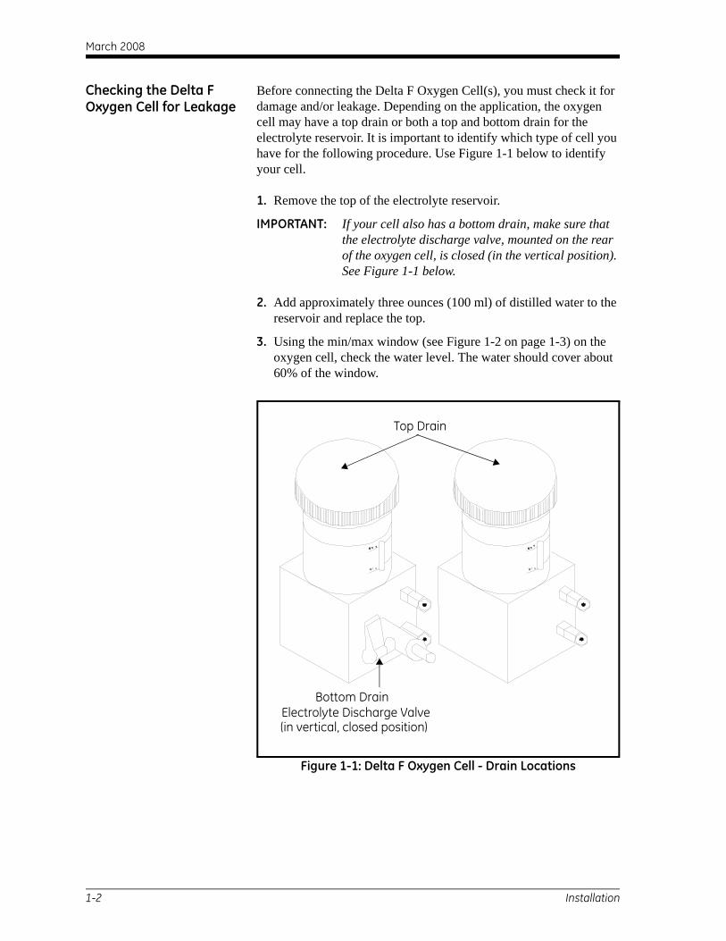
Before connecting the Delta F Oxygen Cell(s), you must check it for damage and/or leakage. Depending on the application, the oxygen cell may have a top drain or both a top and bottom drain for the electrolyte reservoir. It is important to identify which type of cell you have for the following procedure. Use Figure 1-1 below to identify your cell.
1. Remove the top of the electrolyte reservoir.
IMPORTANT: If your cell also has a bottom drain, make sure that the electrolyte discharge valve, mounted on the rear of the oxygen cell, is closed (in the vertical position). See Figure 1-1 below.
2. Add approximately three ounces (100 ml) of distilled water to the reservoir and replace the top.
3. Using the min/max window (see Figure 1-2 on page 1-3) on the oxygen cell, check the water level. The water should cover about 60% of the window.
Figure 1-1: Delta F Oxygen Cell - Drain Locations
M a xM a x
M i n
M ax
M ax
M i n
Top Drain
Bottom DrainElectrolyte Discharge Valve(in vertical, closed position)
1-2 Installation
March 2008
Checking the Delta F Oxygen Cell for Leakage (cont.)
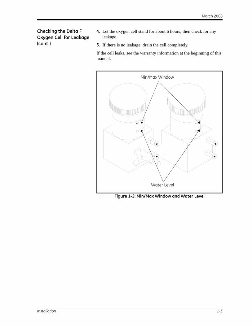
4. Let the oxygen cell stand for about 6 hours; then check for any leakage.
5. If there is no leakage, drain the cell completely.
If the cell leaks, see the warranty information at the beginning of this manual.
Figure 1-2: Min/Max Window and Water Level
M a xM a x
M i n
M ax
M ax
M i n
Min/Max Window
Water Level
Installation 1-3
March 2008
Choosing a Site You should have discussed environmental and installation factors with an applications engineer or field sales person by the time you receive the MMS-3. The equipment should be suited to the application and installation site.
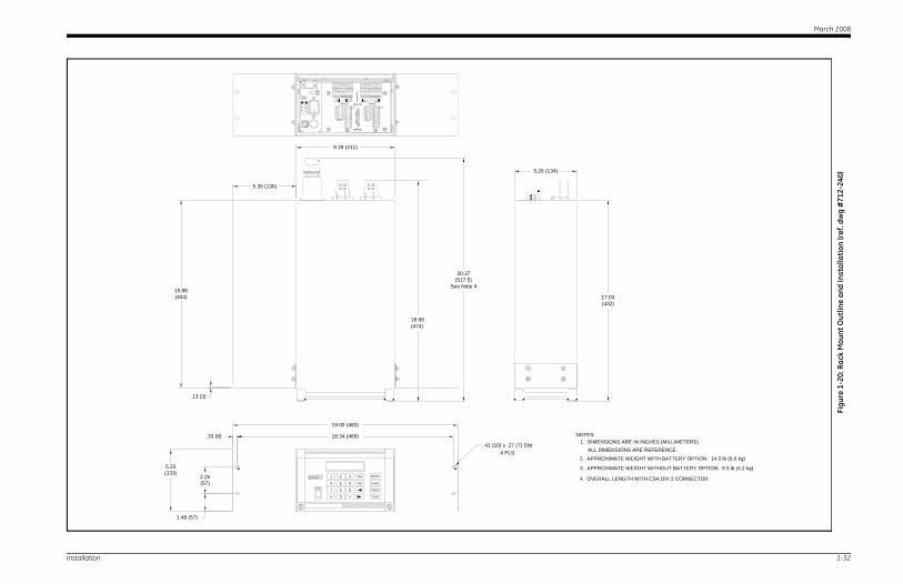
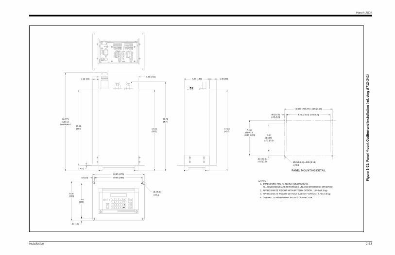
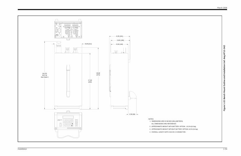
The MMS-3 is available in rack, bench or panel mounts that are suitable for most indoor installations. See the drawings at the end of this chapter for an example of each enclosure.
Before installing the unit, read the guidelines below to verify that you have selected the best installation site.
IMPORTANT: For compliance with the EU’s Low Voltage Directive (IEC 1010), this unit requires an external power disconnect device. The disconnect device for this unit is its power cord.
!WARNING! Division 2 applications may require special installation. Consult the National Electric Code and/or the Canadian
Electrical Code for proper installation requirements.The analyzer must be configured in a suitable
equipment enclosure and installed according to the sections of the National Electric Code, Article 500, and
Canadian Electrical Code, Section 18, that pertain to the hazardous environment classification in which the
electronics will be used.
• Choose an installation site for the probes and sample systems that is as close to the process line as possible. Avoid long lengths of connecting tubing. If long distances are unavoidable, a fast sampling by-pass loop is recommended. Do not install any other components, such as filters, ahead of the probes or sample system unless instructed by GE Sensing to do so.
• Observe all normal safety precautions. Use probes within their maximum pressure and temperature ratings.
• Although the MMS-3 may not need to be accessed during normal operation, install the electronics unit at a convenient location for programming, testing and servicing. A control room or instrument shed are typical locations.
1-4 Installation
March 2008
Choosing a Site (cont.) • Locate the electronics unit away from high temperatures, strong electrical transients, mechanical vibrations, corrosive atmospheres, and any other conditions that could damage or interfere with the MMS-3 operation. See Chapter 3, Specifications, for limits.
• Protect the probe cables from excessive physical strain (bending, pulling, twisting, etc.). In addition, do not subject the cables to temperatures above 65°C (149°F) or below –50°C (–58°F).
• Observe the proper cable restrictions for the probes as follows:
• The M Series and TF Series probes require specially shielded cable. You can locate the M and TF probes up to 600 m (2,000 ft) from the MMS-3. If you are measuring pressure with a TF probe, the cable length should not exceed 152 m (500 ft).
• The Delta-F Oxygen Cell uses a four-wire shielded cable (22 AWG). Cells with a range from 0 to 1/10/100 ppmv or 0 to 0.5/5/50 ppmv can be located up to 15 m (50 ft) away. All other cells can be located up to 91 m (300 ft) away.
Consult GE Sensing for remote location of the oxygen cell and cable restrictions for other sensors.
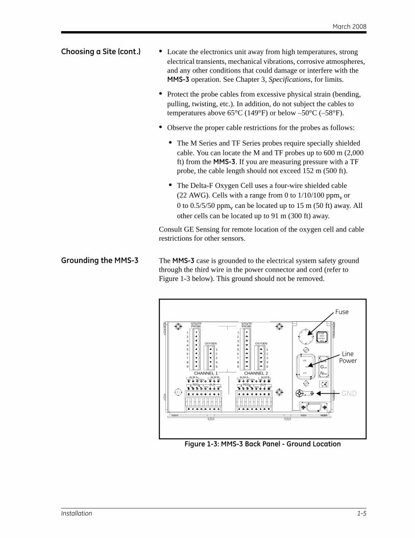
Grounding the MMS-3 The MMS-3 case is grounded to the electrical system safety ground through the third wire in the power connector and cord (refer to Figure 1-3 below). This ground should not be removed.
Figure 1-3: MMS-3 Back Panel - Ground Location
ALM BALM AC
RECA
NO
RTNB
RTNNC
+24V1 2
NO C
AUX
NCALM BALM A
RTN
BA REC
CNO NC
1 2RTN
NO C
AUX+24V
NC
OXYGEN
7
98
6543
3
54
12
7
98
6543
OXYGEN
3
54
12
STD/TFPROBE
12
12
STD/TFPROBE
SLO-BLO3AG
ine
eut
GN
Lnd
1/2 AMP250V
CHANNEL 1 CHANNEL 2
Fuse
LinePower
GND
Installation 1-5
March 2008
Moisture/Temperature Probe Considerations
The M Series and TF Series probes consist of an aluminum oxide sensor mounted on a connector head. Standard probe mounts include a protective stainless-steel shield.
The probe sensor materials and housing maximize durability and insure a minimum of water-adsorbing surfaces in the vicinity of the aluminum oxide surface. A sintered stainless-steel shield is used to protect the sensor from high flow rates and particulate matter. The shield should not be removed except upon advice from GE Sensing.
The sensor has been designed to withstand normal shock and vibration. You should make sure that the active sensor surface is never touched or allowed to come into direct contact with foreign objects, since this may adversely affect performance.
Observing these few simple precautions will result in a long and useful probe life. GE Sensing recommends that probe calibration be checked routinely, at 6-month intervals, or as recommended by our applications engineers for your particular application.
The probe will measure the water vapor pressure in its immediate vicinity; therefore, readings will be influenced by its proximity to the system walls, materials of construction, and other environmental factors. The sensor can be operated under vacuum or pressure, flowing or static conditions.
Observe the following environmental precautions.
Temperature Range The standard probe is operable from –110°C to +70°C (–166°F to 158°F).
Moisture Condensation Be sure the temperature is at least 10°C (18°F) higher than the dew/frost point temperature. If this condition is not maintained, moisture condensation could occur on the sensor or in the sample system, which will cause reading errors. If this happens, dry out the probe following the procedures outlined in Appendix A, Application of the Hygrometer, in the Service Manual.
1-6 Installation
March 2008
Static or Dynamic Use The sensor performs equally well in still air or where considerable flow occurs. Its small size makes it ideal for measuring moisture conditions within completely sealed containers or dry boxes. It will also perform well under gas flow conditions as high as 10,000 cm/sec and liquid flow conditions to 10 cm/sec. Refer to Appendix A, Application of the Hygrometer, in the Service Manual, for maximum flow rates in gases and liquids.
Pressure The moisture probe always senses the correct water vapor pressure regardless of total ambient pressure. The moisture sensor measures water vapor under vacuum or high pressure conditions from as little as 5 µm Hg to as high as 5,000 psi total pressure.
Long-Term Storage & Operational Stability
Sensors are not affected by continuous abrupt humidity changes or damaged by exposure to saturation conditions even when stored. However, you should store probes in their original shipping container in a clean, dry location. If the probe is saturated during storage, refer to Moisture Condensation on page 1-6 before installing the probe. For best performance, do not store probes longer than one to two years from their calibration date.
Freedom from Interference
The sensor is completely unaffected by the presence of a wide variety of gases or organic liquids. Large concentrations of hydrocarbon gases, Freon®, ozone, carbon dioxide, carbon monoxide, and hydrogen have no effect on sensor water vapor indications. The sensor will operate properly in a multitude of gaseous or non-conductive liquid environments.
Corrosive Materials Avoid all materials that are corrosive or otherwise damaging to aluminum or aluminum oxide. These include strongly acidic or basic materials and primary amines.
Installation 1-7
March 2008
Sample System Guidelines
A sample system is required for oxygen measurement and, although not mandatory, is highly recommended for moisture measurement. The purpose of a sample system is to condition or control a sample stream to within the specifications of a probe. The application requirements determine the design of the sample system. GE Sensing applications engineers will make recommendations based on the following general guidelines.
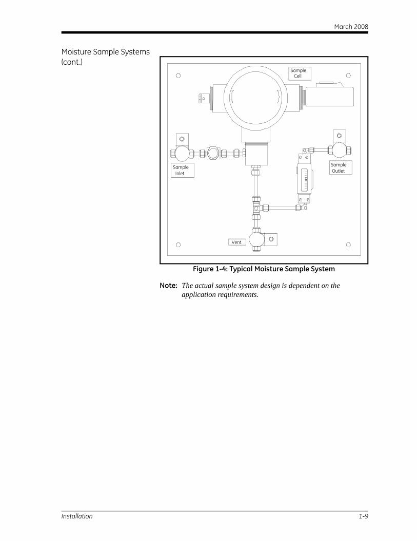
Moisture Sample Systems Typically, sample systems should be kept very simple. They should contain as few components as possible and all or most of those components should be located downstream of the measurement probe. Figure 1-4 on page 1-9 shows an example of a basic sample system consisting of an explosion-proof housing with a sample cell, a filter, a flow meter, a vent valve and two-shut off valves, one at the inlet and one at the outlet.
The sample system components should not be made of any material that will affect measurements. A sample system may include a filter to remove particulates from the sample stream or a pressure regulator to reduce or control the pressure of the stream. However, most common filters and pressure regulators are not suitable for sample systems because they have wetted parts that may absorb or release components (such as moisture) into the sample stream. They may also allow ambient contamination to enter the sample stream. In general, you should use stainless steel material for all wetted parts.
Contact GE Sensing for further instructions.
1-8 Installation
March 2008
Moisture Sample Systems (cont.)
Figure 1-4: Typical Moisture Sample System
Note: The actual sample system design is dependent on the application requirements.
Sample Cell
Sample Inlet
Sample Outlet
Vent
Installation 1-9

March 2008
Oxygen Sample Systems Oxygen sample systems are required. Sample systems can be ordered from GE Sensing for bench or wall mounting. You can also build your own sample system by using the following guidelines.
IMPORTANT: The GE Sensing warranty will be voided, if the sample system does not have a relief valve.
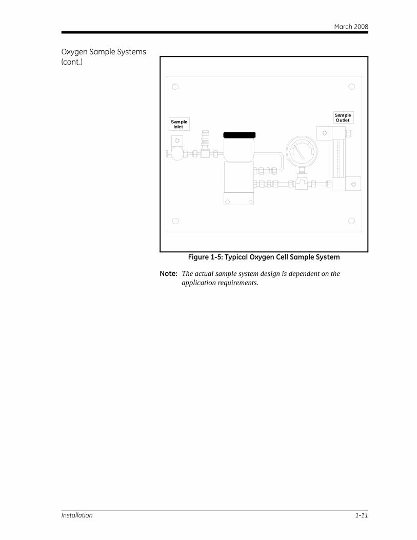
The basic sample system requirements are as follows (see Figure 1-5 on page 1-11):
1. The oxygen cell requires a sample gas flow of 2.0 to 2.5 SCFH.
2. The sample gas pressure in the cell must be between 0.0 and 1.0 psig. The pressure must not exceed 1.0 psig.
3. A 10 psig pressure relief valve installed upstream of the oxygen cell is required to prevent over-pressure.
4. A flow meter is required to measure the flow.
5. A pressure gauge is required to measure the pressure.
6. A flow regulating or needle valve is required to regulate flow and should be located upstream of the cell.
7. A pressure regulator is required for sample gas supplies of 50 psig or greater.
If a sample pump is required to draw a sample to the oxygen cell, the pump should be installed downstream of the oxygen cell. This will also require you to install a vacuum relief valve set at 1.0 psig between the oxygen cell and the pump.
1-10 Installation
March 2008
Oxygen Sample Systems (cont.)
Figure 1-5: Typical Oxygen Cell Sample System
Note: The actual sample system design is dependent on the application requirements.
Sample Inlet
Sample Outlet
Installation 1-11
March 2008
Mounting the Hygrometer System
Mounting the hygrometer system consists of mounting the electronics unit, the probes, and the sample system(s).
Mounting the Electronics Unit
Use the outline and dimension drawings at the end of this chapter to mount the MMS-3. These drawings provide clearance and other mounting dimensions needed to prepare the site for mounting.
IMPORTANT: For compliance with the EU’s Low Voltage Directive (IEC 1010), this unit requires an external power disconnect device such as a switch or circuit breaker. The disconnect device must be marked as such, clearly visible, directly accessible, and located within 1.8 m (6 ft) of the MMS-3. The power cord is the main disconnect device.
Be sure to follow the guidelines outlined in Choosing a Site on page 1-4 before mounting the enclosure.
Note: You may want to make probe, Delta F Oxygen Cell, recorder, and alarm connections before mounting the enclosure, if the installation location does not provide enough room for these connections to be made easily after installation.
Mounting the Sample System
The sample system is normally fastened to a metal plate that has four mounting holes. GE Sensing also provides the sample system in an enclosure if requested. In either case, mount the sample system plate or enclosure with four bolts — one in each corner. If you ordered sample system outline and dimensions drawings, they will be included in your shipment.
Connect the sample system inlet, outlet to the process, and return using the appropriate fittings or an appropriate NPT adapter.
Caution!Do not start a flow through the system until allprobes and transmitters are properly installed.
Mounting the Oxygen Cell Assembly
If your oxygen cell is not mounted into a sample system, refer to Figure 1-19 on page 1-31 to mount the cell.
1-12 Installation
March 2008
Installing the Probes After you mount the sample system you must insert moisture probes into the sample cells. In addition, you must check, prepare, and connect oxygen cells (if used) to the gas line.
Moisture Probes GE Sensing M Series and TF Series moisture probes have 3/4-16 straight threads with an o-ring to secure probes into the sample system or directly into the process line. Other fittings are available for special applications.
Caution! If you are mounting the moisture probes directly into
the process line, you must consult GE Sensing forproper installation instructions and precautions.
Moisture probes are usually installed into a sample system. The sample system protects the probes from coming into contact with damaging elements in the process. Moisture probes are installed into a cylindrical shaped container, called the sample cell, that is included as part of your sample system. (The sample cell is labeled on the sample system plate.)
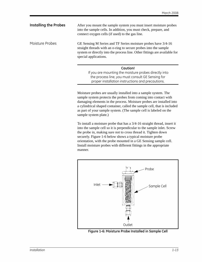
To install a moisture probe that has a 3/4-16 straight thread, insert it into the sample cell so it is perpendicular to the sample inlet. Screw the probe in, making sure not to cross thread it. Tighten down securely. Figure 1-6 below shows a typical moisture probe orientation, with the probe mounted in a GE Sensing sample cell. Install moisture probes with different fittings in the appropriate manner.
Figure 1-6: Moisture Probe Installed in Sample Cell
Inlet
Outlet
Sample Cell
Probe
Installation 1-13
March 2008
Moisture Probes (cont.) Note: Standard moisture probes have a sintered stainless-steel shield that protects the aluminum oxide sensor. Leave the shield in place for maximum protection.
It is important to eliminate all leaks (whether in gas or liquid applications, for safety reasons) and to be sure that measurements are not affected by ambient contamination. For gas applications, you should check for leaks using a soap bubble solution.
Pressure Sensor If a pressure measurement is required, and for some reason the TF probe pressure option is not used, you can connect a separate pressure sensor to an auxiliary input.
The MMS-3 uses any type of 0/4 to 20 mA or a 0 to 2 V pressure transducer or transmitter. GE Sensing offers two types of pressure transmitters: the P40 and P40X. The P40 has a 1/4-inch threaded NPTM fitting and the P40X has a 1/2-inch threaded NPTF fitting for mounting directly into the process line or into a sample system.
Caution!If you are mounting the pressure transmitters directly into the process line, consult GE Sensing for proper installation
instructions and precautions.
Always mount the pressure transmitter directly downstream of the moisture probe in order to measure the pressure at the point of the moisture measurement.
1-14 Installation
March 2008
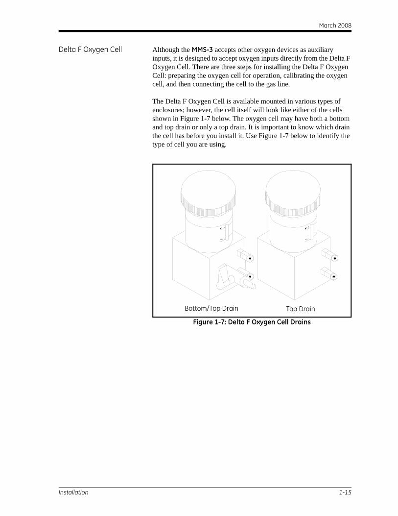
Delta F Oxygen Cell Although the MMS-3 accepts other oxygen devices as auxiliary inputs, it is designed to accept oxygen inputs directly from the Delta F Oxygen Cell. There are three steps for installing the Delta F Oxygen Cell: preparing the oxygen cell for operation, calibrating the oxygen cell, and then connecting the cell to the gas line.
The Delta F Oxygen Cell is available mounted in various types of enclosures; however, the cell itself will look like either of the cells shown in Figure 1-7 below. The oxygen cell may have both a bottom and top drain or only a top drain. It is important to know which drain the cell has before you install it. Use Figure 1-7 below to identify the type of cell you are using.
Figure 1-7: Delta F Oxygen Cell Drains
M a xM a x
M i n
M ax
M ax
M i n
Bottom/Top Drain Top Drain
Installation 1-15
March 2008
Preparing the Oxygen Cell To prepare the oxygen cell for operation, you must fill it with the electrolyte that has been supplied in a plastic bottle.
!WARNING! The electrolyte contains Potassium Hydroxide that is
harmful if it comes in contact with eyes or skin.Consult your company safety personnel forproper procedures for handling electrolyte.
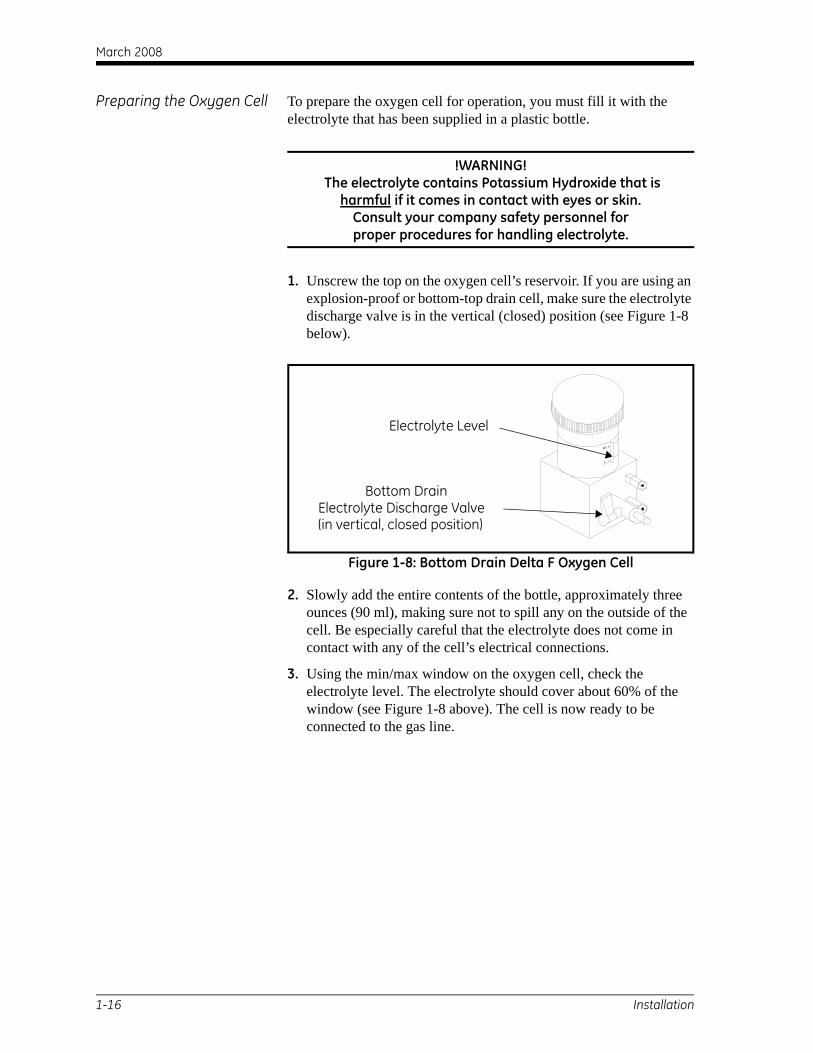
1. Unscrew the top on the oxygen cell’s reservoir. If you are using an explosion-proof or bottom-top drain cell, make sure the electrolyte discharge valve is in the vertical (closed) position (see Figure 1-8 below).
Figure 1-8: Bottom Drain Delta F Oxygen Cell
2. Slowly add the entire contents of the bottle, approximately three ounces (90 ml), making sure not to spill any on the outside of the cell. Be especially careful that the electrolyte does not come in contact with any of the cell’s electrical connections.
3. Using the min/max window on the oxygen cell, check the electrolyte level. The electrolyte should cover about 60% of the window (see Figure 1-8 above). The cell is now ready to be connected to the gas line.
Ma x
Ma x
M i n
Electrolyte Level
Bottom DrainElectrolyte Discharge Valve(in vertical, closed position)
1-16 Installation
March 2008
Preparing the Oxygen Cell (cont.)
4. Replace the top of the oxygen cell.
Note: Once you add the electrolyte, DO NOT add additional electrolyte to the reservoir. If the level falls below the minimum level, refer to Checking and Replenishing the Electrolyte in the Delta F Oxygen Cell in Chapter 2 of the Service Manual to replenish the cell.
5. Calibrate the oxygen cell as described in Calibrating the Delta F Oxygen Cell in Chapter 2 of the Service Manual. After you calibrate the cell, connect it to the gas line as described in the following section.
Note: Oxygen cells are calibrated using nitrogen. If you plan to use your cell with a gas other than nitrogen, you must enter a current multiplier as described in Delta F Oxygen Cell Background Gas Correction Factors in Chapter 2 of the Service Manual.
Connecting the Oxygen Sample System to the Gas Line
To connect the oxygen sample system to the process line, attach a 1/8” O.D. (outside diameter) tube to the 1/8” sample gas inlet fitting using a Swagelok® or equivalent mating connector. Avoid using plastic and rubber in any tubing or fittings that are included in the inlet gas lines.
Caution!Do not connect the oxygen cell outlet to flow-restricting
devices, pressure lines, or vacuum lines.Pressure differentials across the cell sensorin excess of 1 psig could damage the cell.
If the gas being monitored does not create a safety hazard, vent it to atmosphere at the sample system outlet. If venting the gas to atmosphere causes a safety hazard, vent the gas to a safe location. Make sure the venting system does not create a back pressure to the oxygen cell.
The vented sample will not be corrosive if you install and operate the cell properly.
Installation 1-17
March 2008
Making Electrical Connections
!WARNING!To ensure the safe operation of this unit, you must install and operate the MMS-3 as described in this startup guide.
Also, be sure to follow all applicable safety codes and regulations for installing electrical equipment in your area.
!WARNING!Turn off the MMS-3 before making any connections.
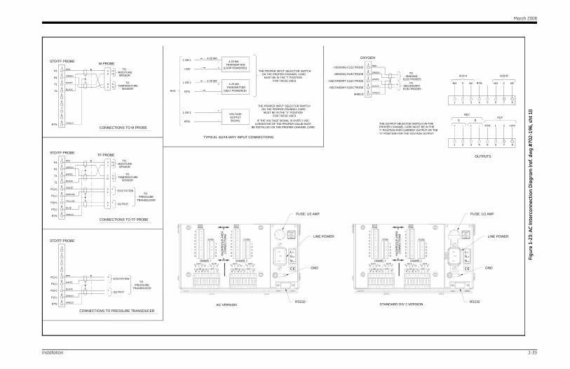
Make all connections to the back of the meter (refer to Figure 1-9 on page 1-19). The larger panel is separated into two sections, one for each channel.
Making Channel Connections
Make connections by placing the press lock lever into the desired terminal. One press lock lever is supplied with each terminal block. Press and hold the lever against the terminal block and insert the stripped and tinned portion of the wire into the terminal. Release the lever to secure the connection.
IMPORTANT: To maintain good contact at each terminal block and to avoid damaging the pins on the connector, pull the connector straight off (not at an angle), make cable connections while the connector is away from the unit, and push the connector straight on (not at an angle) when the wiring is complete.
Proper connections and cabling are extremely important to accurate measurement. Be sure to use the correct cable type for each probe, and make sure that the cables are not damaged during installation. If you are not using a GE Sensing-supplied cable, or you are using a modified cable, read the following section carefully.
1-18 Installation
March 2008
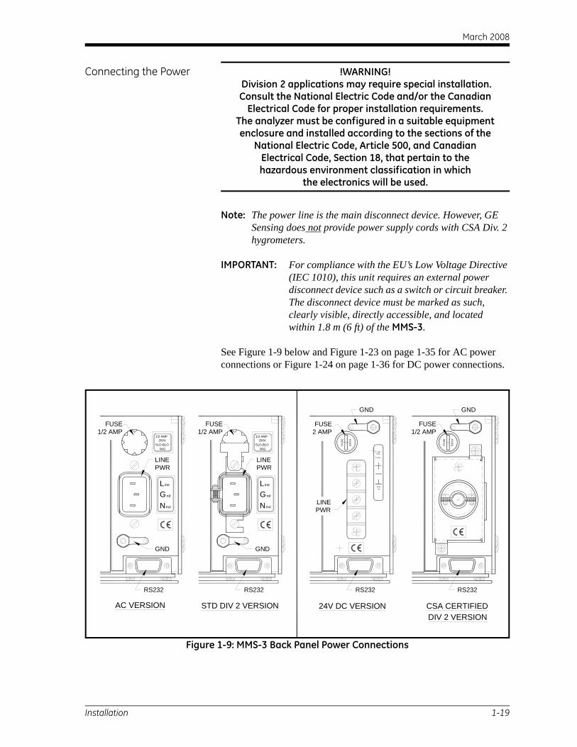
Connecting the Power !WARNING! Division 2 applications may require special installation. Consult the National Electric Code and/or the Canadian
Electrical Code for proper installation requirements.The analyzer must be configured in a suitable equipment enclosure and installed according to the sections of the
National Electric Code, Article 500, and CanadianElectrical Code, Section 18, that pertain to thehazardous environment classification in which
the electronics will be used.
Note: The power line is the main disconnect device. However, GE Sensing does not provide power supply cords with CSA Div. 2 hygrometers.
IMPORTANT: For compliance with the EU’s Low Voltage Directive (IEC 1010), this unit requires an external power disconnect device such as a switch or circuit breaker. The disconnect device must be marked as such, clearly visible, directly accessible, and located within 1.8 m (6 ft) of the MMS-3.
See Figure 1-9 below and Figure 1-23 on page 1-35 for AC power connections or Figure 1-24 on page 1-36 for DC power connections.
Figure 1-9: MMS-3 Back Panel Power Connections
SLO-BLO
Neut
Gnd
Line
3AG
250V1/2 AMP
ndGNeut
L ine
SLO-BLO3AG
250V1/2 AMP
STD DIV 2 VERSIONAC VERSION
2 AMP FUSE
24 VDC
FS
EU
FUS
E UE
SF E
SUF
24V DC VERSION CSA CERTIFIED
LINEPWR
LINEPWR
FUSE2 AMP
FUSE1/2 AMP
GND GND
GND GND
LINEPWR
RS232 RS232 RS232 RS232
FUSE1/2 AMP
FUSE1/2 AMP
DIV 2 VERSION
Installation 1-19
March 2008
Connecting Moisture Probes
GE Sensing manufactures a variety of moisture probes for the MMS-3. The most commonly used are the M Series and TF Series.
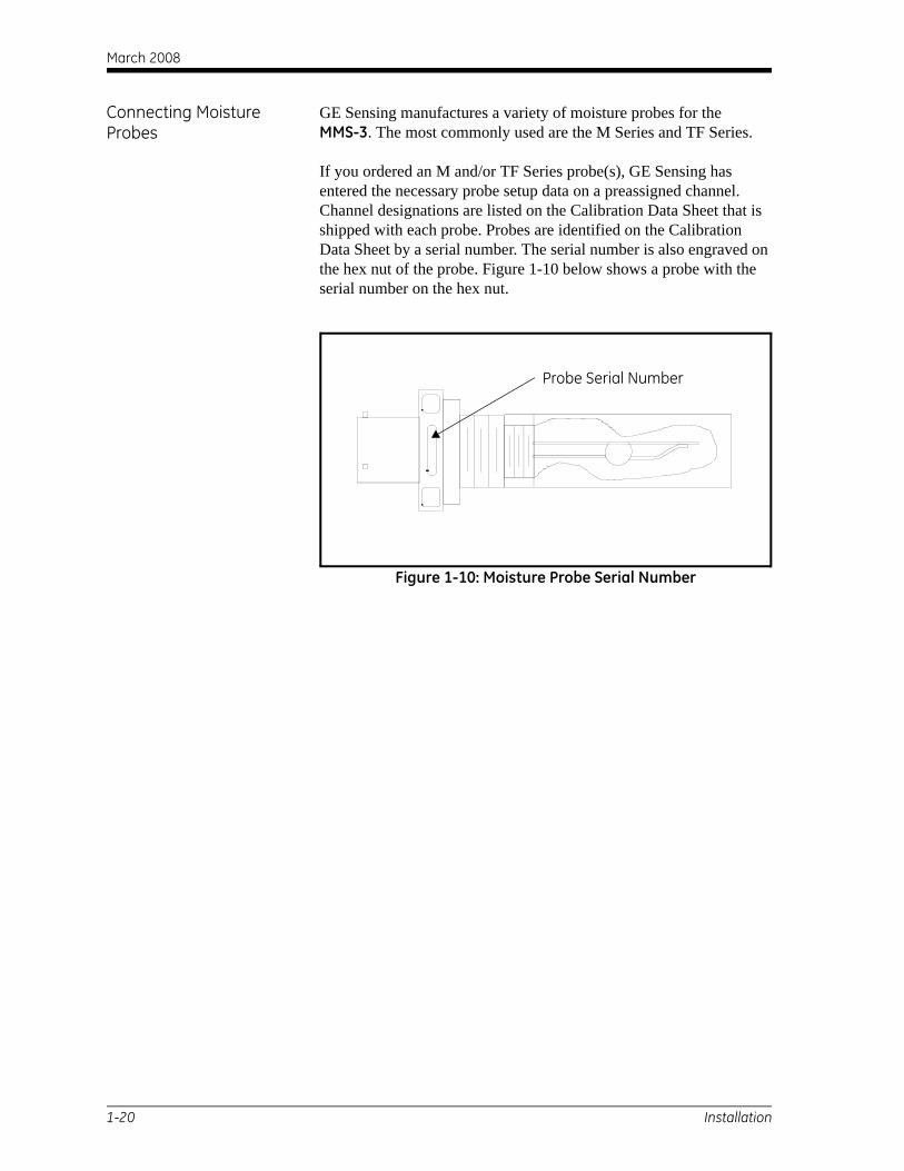
If you ordered an M and/or TF Series probe(s), GE Sensing has entered the necessary probe setup data on a preassigned channel. Channel designations are listed on the Calibration Data Sheet that is shipped with each probe. Probes are identified on the Calibration Data Sheet by a serial number. The serial number is also engraved on the hex nut of the probe. Figure 1-10 below shows a probe with the serial number on the hex nut.
Figure 1-10: Moisture Probe Serial Number
Probe Serial Number
1-20 Installation

March 2008
M Series Probe M Series probes are primarily used for moisture measurement, but can be ordered to measure temperature as well. If ordered, an optional temperature thermistor is included in the moisture probe and requires an additional connection.
You should connect the M Series Probe to the electronics unit with a four-wire shielded cable with a bayonet-type connector. The M Series Probe may be located up to 600 m (2000 ft) from the MMS-3. Consult GE Sensing for longer cable lengths.
Before making electrical connections, connect the cable to the probe by inserting the bayonet-type connector onto the probe and twisting the shell clockwise until it snaps into a locked position (approximately 1/8 of a turn). If you are not using a GE Sensing- supplied cable, refer to Figure 1-11 below to make proper pin connections to a bayonet-type connector.
Figure 1-11: M Series Probe Cable Assembly
NOTICE FOR BASEEFA CERTIFICATION The M Series probe may not be capable of withstanding
the 500 V insulation test required by clause 5.7 of EN50 020 when installed in the process media. This must be taken into
account in any installation in which it is used. (See Cert. #Ex95C2002X in its entirety.) Copies of official BASEEFA
documentation (certificates of compliance, licenses, etc.)are to be made in their entirety.
9
8
7
6
5
4
3
2
1H1
H2
T1
T2
RTN Shield
White
Black
Green
Red
A
B
D
C
T2
H2
T1
H1
STD ProbeTerminal Block
M Series Probe
ToMoistureSensor
SensorTemp.
To
PinsConnectorBayonet
Installation 1-21
March 2008
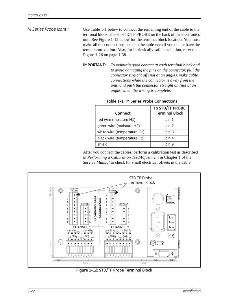
M Series Probe (cont.) Use Table 1-1 below to connect the remaining end of the cable to the terminal block labeled STD/TF PROBE on the back of the electronics unit. See Figure 1-12 below for the terminal block location. You must make all the connections listed in the table even if you do not have the temperature option. Also, for intrinsically safe installation, refer to Figure 1-26 on page 1-38.
IMPORTANT: To maintain good contact at each terminal block and to avoid damaging the pins on the connector, pull the connector straight off (not at an angle), make cable connections while the connector is away from the unit, and push the connector straight on (not at an angle) when the wiring is complete.
After you connect the cables, perform a calibration test as described in Performing a Calibration Test/Adjustment in Chapter 1 of the Service Manual to check for small electrical offsets in the cable.
Figure 1-12: STD/TF Probe Terminal Block
Table 1-1: M Series Probe Connections
Connect:To STD/TF PROBE
Terminal Blockred wire (moisture H1) pin 1green wire (moisture H2) pin 2white wire (temperature T1) pin 3black wire (temperature T2) pin 4shield pin 9
ALM BALM AC
RECA
NO
RTNB
RTNNC
+24V1 2
NO C
AUX
NCALM BALM A
RTN
BA REC
CNO NC
1 2RTN
NO C
AUX+24V
NC
OXYGEN
7
98
6543
3
54
12
7
98
6543
OXYGEN
3
54
12
STD/TFPROBE
12
12
STD/TFPROBE
SLO-BLO3AG
ine
eut
GN
Lnd
1/2 AMP250V
CHANNEL 1 CHANNEL 2
HA
ZAR
DO
US
AR
EAC
ON
NEC
TIO
NS
STD TF ProbeTerminal Block
1-22 Installation
March 2008
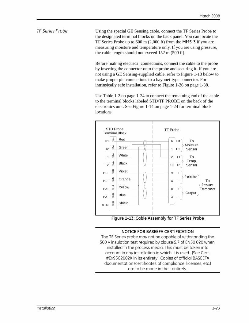
TF Series Probe Using the special GE Sensing cable, connect the TF Series Probe to the designated terminal blocks on the back panel. You can locate the TF Series Probe up to 600 m (2,000 ft) from the MMS-3 if you are measuring moisture and temperature only. If you are using pressure, the cable length should not exceed 152 m (500 ft).
Before making electrical connections, connect the cable to the probe by inserting the connector onto the probe and securing it. If you are not using a GE Sensing-supplied cable, refer to Figure 1-13 below to make proper pin connections to a bayonet-type connector. For intrinsically safe installation, refer to Figure 1-26 on page 1-38.
Use Table 1-2 on page 1-24 to connect the remaining end of the cable to the terminal blocks labeled STD/TF PROBE on the back of the electronics unit. See Figure 1-14 on page 1-24 for terminal block locations.
Figure 1-13: Cable Assembly for TF Series Probe
NOTICE FOR BASEEFA CERTIFICATIONThe TF Series probe may not be capable of withstanding the
500 V insulation test required by clause 5.7 of EN50 020 when installed in the process media. This must be taken into
account in any installation in which it is used. (See Cert. #Ex95C2002X in its entirety.) Copies of official BASEEFA
documentation (certificates of compliance, licenses, etc.)are to be made in their entirety.
9
8
7
6
5
4
3
2
1H1
H2
T1
T2
RTN Shield
Black
White
Green
Red
10
2
1
6
T2
H2
T1
H1
STD ProbeTerminal Block
TF Probe
ToMoistureSensor
SensorTemp.
To
8
3
4
9
+
–
–
+
Output
Excitation
TransducerPressure
To
Blue
Yellow
Orange
Violet
P2+
P2–
P1–
P1+
Installation 1-23
March 2008
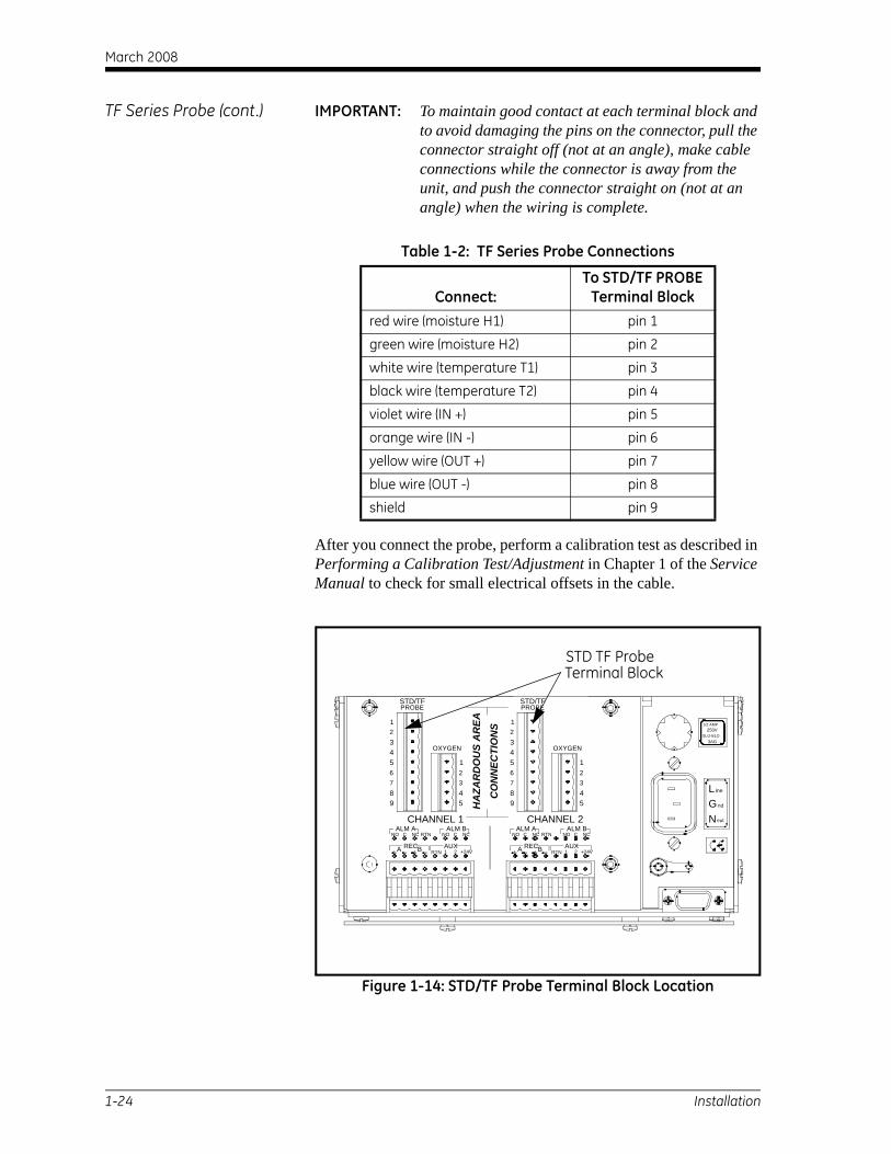
TF Series Probe (cont.) IMPORTANT: To maintain good contact at each terminal block and to avoid damaging the pins on the connector, pull the connector straight off (not at an angle), make cable connections while the connector is away from the unit, and push the connector straight on (not at an angle) when the wiring is complete.
After you connect the probe, perform a calibration test as described in Performing a Calibration Test/Adjustment in Chapter 1 of the Service Manual to check for small electrical offsets in the cable.
Figure 1-14: STD/TF Probe Terminal Block Location
Table 1-2: TF Series Probe Connections
Connect:To STD/TF PROBE
Terminal Blockred wire (moisture H1) pin 1
green wire (moisture H2) pin 2
white wire (temperature T1) pin 3
black wire (temperature T2) pin 4
violet wire (IN +) pin 5
orange wire (IN -) pin 6
yellow wire (OUT +) pin 7
blue wire (OUT -) pin 8
shield pin 9
ALM BALM AC
RECA
NO
RTNB
RTNNC
+24V1 2
NO C
AUX
NCALM BALM A
RTN
BA REC
CNO NC
1 2RTN
NO C
AUX+24V
NC
OXYGEN
7
98
6543
3
54
12
7
98
6543
OXYGEN
3
54
12
STD/TFPROBE
12
12
STD/TFPROBE
SLO-BLO3AG
ine
eut
GN
Lnd
1/2 AMP250V
CHANNEL 1 CHANNEL 2
HA
ZAR
DO
US
AR
EA
CO
NN
ECTI
ON
S
STD TF ProbeTerminal Block
1-24 Installation
March 2008
Connecting the Delta F Oxygen Cell
The Delta F Oxygen Cell is available in a general purpose model with standard or VCR® fittings. The oxygen cell can also be mounted in a weatherproof enclosure (R4) for outdoor applications or an explosion-proof enclosure (R7) for hazardous areas.
Caution!Do not power up your MMS-3 without establishing a flow
through the Delta F Oxygen Cell (see page 1-30).
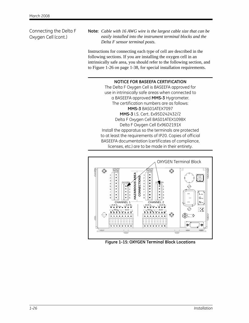
Each model of the oxygen cell has a set of sensing and secondary electrodes. Make connections from the electrodes on the cell to the terminal block labeled OXYGEN on the back of the electronics unit (see Figure 1-15 on page 1-26).
IMPORTANT: To maintain good contact at each terminal block and to avoid damaging the pins on the connector, pull the connector straight off (not at an angle), make cable connections while the connector is away from the unit, and push the connector straight on (not at an angle) when the wiring is complete.
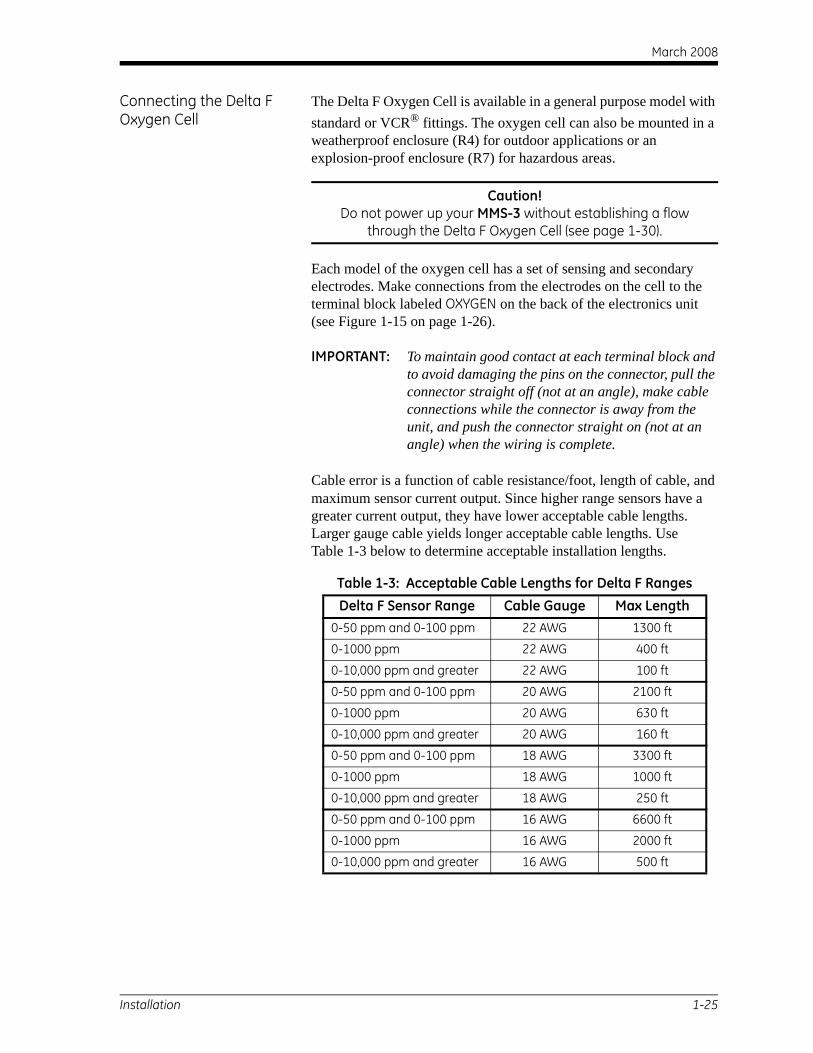
Cable error is a function of cable resistance/foot, length of cable, and maximum sensor current output. Since higher range sensors have a greater current output, they have lower acceptable cable lengths. Larger gauge cable yields longer acceptable cable lengths. Use Table 1-3 below to determine acceptable installation lengths.
Table 1-3: Acceptable Cable Lengths for Delta F RangesDelta F Sensor Range Cable Gauge Max Length
0-50 ppm and 0-100 ppm 22 AWG 1300 ft
0-1000 ppm 22 AWG 400 ft
0-10,000 ppm and greater 22 AWG 100 ft
0-50 ppm and 0-100 ppm 20 AWG 2100 ft
0-1000 ppm 20 AWG 630 ft
0-10,000 ppm and greater 20 AWG 160 ft
0-50 ppm and 0-100 ppm 18 AWG 3300 ft
0-1000 ppm 18 AWG 1000 ft
0-10,000 ppm and greater 18 AWG 250 ft
0-50 ppm and 0-100 ppm 16 AWG 6600 ft
0-1000 ppm 16 AWG 2000 ft
0-10,000 ppm and greater 16 AWG 500 ft
Installation 1-25
March 2008
Connecting the Delta F Oxygen Cell (cont.)
Note: Cable with 16 AWG wire is the largest cable size that can be easily installed into the instrument terminal blocks and the Delta F sensor terminal posts.
Instructions for connecting each type of cell are described in the following sections. If you are installing the oxygen cell in an intrinsically safe area, you should refer to the following section, and to Figure 1-26 on page 1-38, for special installation requirements.
NOTICE FOR BASEEFA CERTIFICATIONThe Delta F Oxygen Cell is BASEEFA approved foruse in intrinsically safe areas when connected to
a BASEEFA approved MMS-3 Hygrometer.The certification numbers are as follows:
MMS-3 BAS01ATEX7097MMS-3 I.S. Cert. Ex95D242432/2
Delta F Oxygen Cell BAS01ATEX1098XDelta F Oxygen Cell Ex96D2191X
Install the apparatus so the terminals are protectedto at least the requirements of IP20. Copies of official BASEEFA documentation (certificates of compliance,
licenses, etc.) are to be made in their entirety.
Figure 1-15: OXYGEN Terminal Block Locations
ALM BALM AC
RECA
NO
RTNB
RTNNC
+24V1 2
NO C
AUX
NCALM BALM A
RTN
BA REC
CNO NC
1 2RTN
NO C
AUX+24V
NC
OXYGEN
7
98
6543
3
54
12
7
98
6543
OXYGEN
3
54
12
STD/TFPROBE
12
12
STD/TFPROBE
SLO-BLO3AG
ine
eut
GN
Lnd
1/2 AMP250V
CHANNEL 1 CHANNEL 2
HA
ZAR
DO
US
AR
EAC
ON
NEC
TIO
NS
OXYGEN Terminal Block
1-26 Installation
March 2008
Standard Delta-F Oxygen Cells and Cells with VCR Fittings
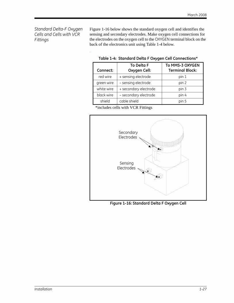
Figure 1-16 below shows the standard oxygen cell and identifies the sensing and secondary electrodes. Make oxygen cell connections for the electrodes on the oxygen cell to the OXYGEN terminal block on the back of the electronics unit using Table 1-4 below..
Figure 1-16: Standard Delta F Oxygen Cell
Table 1-4: Standard Delta F Oxygen Cell Connections*
Connect:To Delta F
Oxygen Cell:To MMS-3 OXYGEN
Terminal Block:red wire + sensing electrode pin 1
green wire – sensing electrode pin 2
white wire + secondary electrode pin 3
black wire – secondary electrode pin 4
shield cable shield pin 5
*includes cells with VCR Fittings
SecondaryElectrodes
SensingElectrodes
Installation 1-27
March 2008
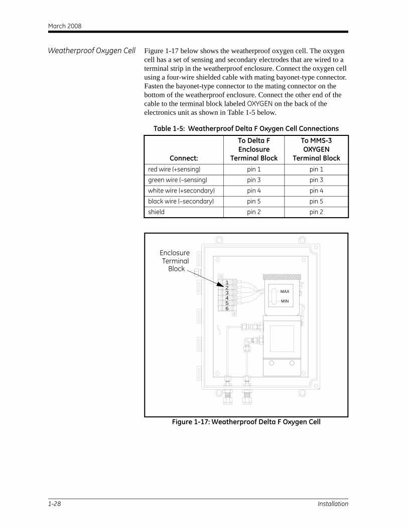
Weatherproof Oxygen Cell Figure 1-17 below shows the weatherproof oxygen cell. The oxygen cell has a set of sensing and secondary electrodes that are wired to a terminal strip in the weatherproof enclosure. Connect the oxygen cell using a four-wire shielded cable with mating bayonet-type connector. Fasten the bayonet-type connector to the mating connector on the bottom of the weatherproof enclosure. Connect the other end of the cable to the terminal block labeled OXYGEN on the back of the electronics unit as shown in Table 1-5 below.
Figure 1-17: Weatherproof Delta F Oxygen Cell
Table 1-5: Weatherproof Delta F Oxygen Cell Connections
Connect:
To Delta F Enclosure
Terminal Block
To MMS-3 OXYGEN
Terminal Blockred wire (+sensing) pin 1 pin 1
green wire (–sensing) pin 3 pin 3
white wire (+secondary) pin 4 pin 4
black wire (–secondary) pin 5 pin 5
shield pin 2 pin 2
MAX
MIN
123456
EnclosureTerminal
Block
1-28 Installation
March 2008
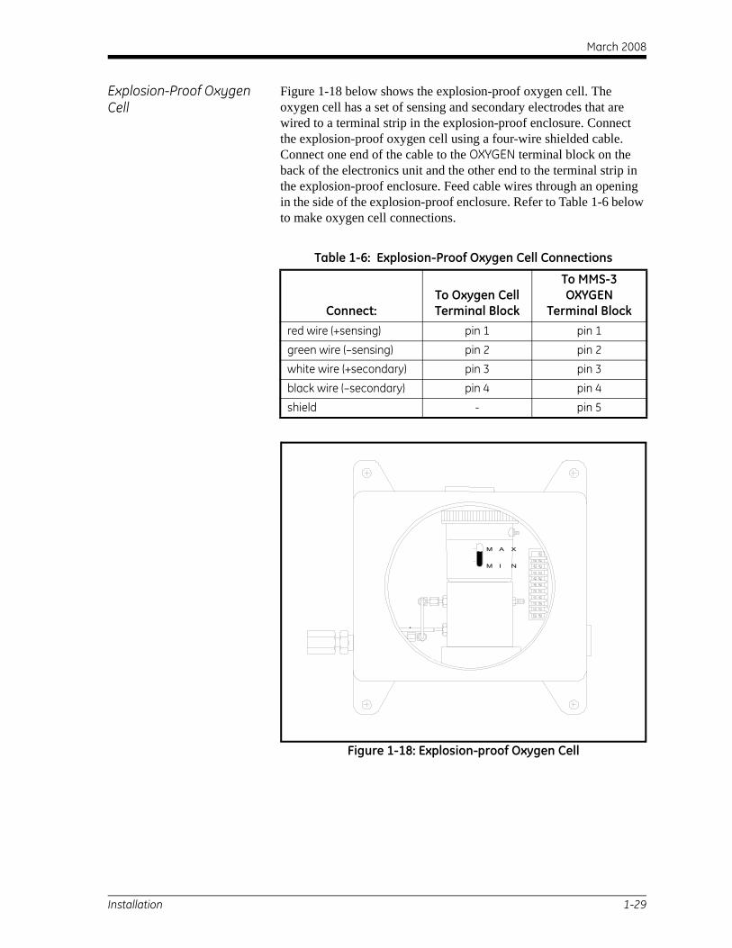
Explosion-Proof Oxygen Cell
Figure 1-18 below shows the explosion-proof oxygen cell. The oxygen cell has a set of sensing and secondary electrodes that are wired to a terminal strip in the explosion-proof enclosure. Connect the explosion-proof oxygen cell using a four-wire shielded cable. Connect one end of the cable to the OXYGEN terminal block on the back of the electronics unit and the other end to the terminal strip in the explosion-proof enclosure. Feed cable wires through an opening in the side of the explosion-proof enclosure. Refer to Table 1-6 below to make oxygen cell connections.
Figure 1-18: Explosion-proof Oxygen Cell
Table 1-6: Explosion-Proof Oxygen Cell Connections
Connect:To Oxygen Cell Terminal Block
To MMS-3 OXYGEN
Terminal Blockred wire (+sensing) pin 1 pin 1
green wire (–sensing) pin 2 pin 2
white wire (+secondary) pin 3 pin 3
black wire (–secondary) pin 4 pin 4
shield - pin 5
M A X
M I N
Installation 1-29
March 2008
Establishing a Gas Flow Through the Oxygen Cell
Caution!Establish a gas sample flow before you power up,
or damage may occur to the oxygen cell.
If you are using an oxygen cell, you must establish a gas flow through the cell before powering up. If you are not using an oxygen cell, proceed to Chapter 2, Initial Setup.
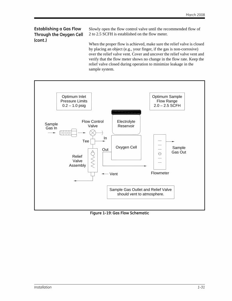
The oxygen cell requires a flow rate of 2 to 2.5 SCFH through the cell. Oxygen cell inlet pressure should be between 0.2 to 1.0 psig. Refer to Figure 1-19 on page 1-31 when establishing a gas sample flow.
Caution!Do not operate the Delta F oxygen cell for extended
periods of time at oxygen concentrations that are over range. Trace and low percent range sensors may be
damaged if exposed to high levels of oxygen, such as air, for long periods (>1 hour) while the MMS-3 is on.
If exposure is unavoidable, either disconnect the oxygen cell from the MMS-3 or equip the sample system with a valve that allows the cell to be switched to purge gas.
Close the flow control valve and adjust the upstream pressure as required. GE Sensing recommends about 2 to 10 psig upstream of the flow control valve, depending on which valve is installed in the sample system.
To safeguard against over-pressurizing the oxygen cell, install a relief valve rated at 10 psig into the gas flow system. If the pressure exceeds 10 psig, the relief valve will open; therefore, there should be no restrictions downstream of the oxygen cell. Use 1/4-inch tubing or larger on the oxygen cell outlet and relief valve outlet. Both outlets should vent to atmosphere if possible.
Caution!Do not tie the relief valve and oxygen cell outlet to a
common outlet line smaller than 1/4 inch. This pressure restriction will damage the oxygen cell. In addition, a relief
valve should be installed in the oxygen sample system.If either of these conditions are not met,
the Delta F Oxygen Cell warranty will be voided.
1-30 Installation
March 2008
Establishing a Gas Flow Through the Oxygen Cell (cont.)
Slowly open the flow control valve until the recommended flow of 2 to 2.5 SCFH is established on the flow meter.
When the proper flow is achieved, make sure the relief valve is closed by placing an object (e.g., your finger, if the gas is non-corrosive) over the relief valve vent. Cover and uncover the relief valve vent and verify that the flow meter shows no change in the flow rate. Keep the relief valve closed during operation to minimize leakage in the sample system.
Figure 1-19: Gas Flow Schematic
Optimum InletPressure Limits0.2 – 1.0 psig
Optimum SampleFlow Range
2.0 – 2.5 SCFH
should vent to atmosphere.Sample Gas Outlet and Relief Valve
Vent
Oxygen Cell
ElectrolyteReservoirSample
Gas In
In
Out
Tee
ReliefValve
Assembly
Flow ControlValve
Flowmeter
SampleGas Out
Installation 1-31
March 2008
1-32
ALL DIMENSIONS ARE REFERENCE.
17.03(432)
6 (134)
3. APPROXIMATE WEIGHT WITHOUT BATTERY OPTION: 9.3 lb (4.2 kg)
NOTES:
2. APPROXIMATE WEIGHT WITH BATTERY OPTION: 14.5 lb (6.6 kg)
1. DIMENSIONS ARE IN INCHES (MILLIMETERS).
4. OVERALL LENGTH WITH CSA DIV 2 CONNECTOR.
Figu
re 1
-20:
Rac
k M
ount
Out
line
and
Inst
alla
tion
(ref
. dw
g #
712-
240)
Installation
ine
nd
eut
GN
L
3AGSLO-BLO
250V1/2 AMP
.13 (3)
15.88(403)
5.22(133)
1.48 (57)
2.25(57)
.33 (8)
19.00 (483)
18.34 (466)
5.2
4 PLS.41 (10) x .27 (7) Slot
MODE
PROG
CHAN
RUN
YES31 2
NO
97 8
0
4 5 6SERIES 3
POWER
MOISTURE MONITOR
18.68
20.37(517.5)
See Note 4
5.35 (136)
8.29 (211)
(474)
March 2008
1-33
ALL DIMENSIONS ARE REFERENCE UNLESS OTHERWISE SPECIFIED.1. DIMENSIONS ARE IN INCHES (MILLIMETERS).
2. APPROXIMATE WEIGHT WITH BATTERY OPTION: 13.9 lb (6.3 kg)
NOTES:
7.450(189.23)
±.005 (0.13) 5.85(148.6)
±.02 (0.5)
.80 (20.3)±.02 (0.5)
9.25 (235.0) ±.02 (0.5).40 (10.2)±.02 (0.5)
10.050 (255.27) ±.005 (0.13)
PANEL MOUNTING DETAIL
Ø.250 (6.4) ±.005 (0.13)4 PLS
3. APPROXIMATE WEIGHT WITHOUT BATTERY OPTION: 8.7 lb (3.9 kg)
4. OVERALL LENGTH WITH CSA DIV 2 CONNECTOR..
Figu
re 1
-21:
Pan
el M
ount
Out
line
and
Inst
alla
tion
(ref
. dw
g #
712-
241)
Installation
18.68(474)
8.25(210)
MOISTURE MONITOR
.40 (10) 10.05 (255)
10.85 (276)
7.45(189)
.40 (10)
15.88(403)
.13 (3)
17.03(432)
1.29 (33) 1.49 (38)5.26 (134)
17.03(432)
Ø.25 (6)4 PLS
eut
nd
ine
8.29 (211)
20.375(517.5)
See Note 4
March 2008
1-34
3. APPROXIMATE WEIGHT WITHOUT BATTERY OPTION: 8.0 lb (3.6 kg)
NOTES:
2. APPROXIMATE WEIGHT WITH BATTERY OPTION: 13.2 lb (6.0 kg)
1. DIMENSIONS ARE IN INCHES (MILLIMETERS).
ALL DIMENSIONS ARE REFERENCE.
4. OVERALL LENGTH WITH CSA DIV 2 CONNECTOR.
Figu
re 1
-22:
Ben
ch M
ount
Out
line
and
Inst
alla
tion
(ref.
dwg
#71
2-24
2)
Installation
2.50 (64)
17.03(432)
6.35 (161)
5.26 (134)
5.85 (149)
MOISTURE MONITOR
ine
eut
nd
18.68(474)
20.375(517.5)
See Note 4
8.29 (211)
March 2008
1-35
RS232
ndGNeut
L ine
GND
LINE POWERSLO-BLO3AG
250V1/2 AMP
FUSE: 1/2 AMP
STANDARD DIV 2 VERSION
ING ELECTRODE
ING ELECTRODE
"V" POSITION FOR THE VOLTAGE OUTPUT"I" POSITION FOR CURRENT OUTPUT OR THEPROPER CHANNEL CARD MUST BE IN THETHE OUTPUT SELECTOR SWITCH ON THE
OXYGEN
ELECTRODESSECONDARY
TO+-
-+
SHIELD
BLACK
WHITE
GREEN
RED
ELECTRODESSENSING
TO
5
4
3
2
1
ARY ELECTRODE
ARY ELECTRODE
SHIELD
OUTPUTS
+
1
- + - RTN 1 2 +24V
A
2 3 4 5 6 7 8
B
RECAUX
1 2 3 4 5 6 7 8
NO C NC RTN
ALM A
NO NCC
ALM B
Figu
re 1
-23:
AC
Inte
rcon
nect
ion
Dia
gram
(ref
. dw
g #
702-
196,
sht
1))
Installation
FUSE: 1/2 AMP
LINE POWER
GND
RS232
SLO-BLO
Neut
G nd
Line
3AG
250V1/2 AMP
AC VERSION
M PROBE
T2T1
H2H1
AB
DC
GREEN
FOR THESE USES
H2-SENS
+SENS
RTN
RTN
TYPICAL AUXILIARY INPUT CONNECTIONS
1 OR 2
1 OR 2 4-20 MA
4-20 MA
BE INSTALLED ON THE PROPER CHANNEL CARDA RESISTOR OF THE PROPER VALUE MUST
IF THE VOLTAGE SIGNAL IS OVER 2 VDC
THE PROPER INPUT SELECTOR SWITCHON THE PROPER CHANNEL CARD
4-20 MATRANSMITTER
MUST BE IN THE "V" POSITION
FOR THESE USESMUST BE IN THE "I" POSITION
ON THE PROPER CHANNEL CARDTHE PROPER INPUT SELECTOR SWITCH
AUX
SIGNALOUTPUTVOLTAGE
(SELF POWERED)
(LOOP POWERED)TRANSMITTER
4-20 MA
+24V
1 OR 2STD/TF PROBE
T2
T1
H1
SENSORTEMPERATURE
TO
SENSORMOISTURE
TO1
2
3
4
5
6
RED
WHITE
BLACK
SHIELD
+SECOND
-SECOND
-
+
-
+
-
+
RTN
8
9
7
H2
ORANGE
YELLOW
BLUE
SHIELD
BLACK
WHITE
P1(-)
P2(+)
P2(-)
RTN9
8
7
P1(+)6
5 VIOLET
T1
T24
3
GREEN
STD/TF PROBE
H12
1 RED
TRANSDUCER
3
94
8 OUTPUT
EXCITATION
-
+
+
-
PRESSURETO
TF PROBE
102
16 TO
MOISTURESENSOR
TEMPERATURESENSOR
T1T2
H1H2
TO
CONNECTIONS TO M PROBE
CONNECTIONS TO TF PROBE
CONNECTIONS TO PRESSURE TRANSDUCER
RTN SHIELD9
8
7
6
5
4
3
STD/TF PROBE
2
1
RED
WHITE
GREEN
BLACKOUTPUT-
+
EXCITATION+-
PRESSURETRANSDUCER
TO
P2(-)
P2(+)
P1(-)
P1(+)

March 2008
1-36
ING ELECTRODE
ING ELECTRODE
"V" POSITION FOR THE VOLTAGE OUTPUT"I" POSITION FOR CURRENT OUTPUT OR THEPROPER CHANNEL CARD MUST BE IN THETHE OUTPUT SELECTOR SWITCH ON THE
OXYGEN
ELECTRODESSECONDARY
TO+-
-+
SHIELD
BLACK
WHITE
GREEN
RED
ELECTRODESSENSING
TO
5
4
3
2
1
RY ELECTRODE
RY ELECTRODE
SHIELD
OUTPUTS
+
1
- + - RTN 1 2 +24V
A
2 3 4 5 6 7 8
B
RECAUX
1 2 3 4 5 6 7 8
NO C NC RTN
ALM A
NO NCC
ALM B
RS232
GND
FUSE: 1/2 AMP
UE
SF E
SUF
CSA CERTIFIED DIV 2 VERSION
NEUT
GND GROUND
NEUTRAL
LINE POWER - CSA CERTIFIED DIV 2
LINE LINE
Figu
re 1
-24:
DC
Inte
rcon
nect
ion
Dia
gram
(ref
. dw
g #
702-
196,
sht
2)
Installation
M PROBE
T2T1
H2H1
AB
DC
GREEN
FOR THESE USES
H2-SENS
+SENS
RTN
RTN
TYPICAL AUXILIARY INPUT CONNECTIONS
1 OR 2
1 OR 2 4-20 MA
4-20 MA
BE INSTALLED ON THE PROPER CHANNEL CARDA RESISTOR OF THE PROPER VALUE MUST
IF THE VOLTAGE SIGNAL IS OVER 2 VDC
THE PROPER INPUT SELECTOR SWITCHON THE PROPER CHANNEL CARD
4-20 MATRANSMITTER
MUST BE IN THE "V" POSITION
FOR THESE USESMUST BE IN THE "I" POSITION
ON THE PROPER CHANNEL CARDTHE PROPER INPUT SELECTOR SWITCH
AUX
SIGNALOUTPUTVOLTAGE
(SELF POWERED)
(LOOP POWERED)TRANSMITTER
4-20 MA
+24V
1 OR 2STD/TF PROBE
T2
T1
H1
SENSORTEMPERATURE
TO
SENSORMOISTURE
TO1
2
3
4
5
6
RED
WHITE
BLACK
SHIELD
+SECONDA
-SECONDA
-
+
-
+
-
+
FUSE: 2 AMP
LINE POWER
GND
RS232
RTN
8
9
7
H2
ORANGE
YELLOW
BLUE
SHIELD
BLACK
WHITE
P1(-)
P2(+)
P2(-)
RTN9
8
7
P1(+)6
5 VIOLET
T1
T24
3
GREEN
STD/TF PROBE
H12
1 RED
TRANSDUCER
3
94
8 OUTPUT
EXCITATION
-
+
+
-
PRESSURETO
TF PROBE
102
16 TO
MOISTURESENSOR
TEMPERATURESENSOR
T1T2
H1H2
TO
CONNECTIONS TO M PROBE
CONNECTIONS TO TF PROBE
CONNECTIONS TO PRESSURE TRANSDUCER
RTN SHIELD9
8
7
6
5
4
3
STD/TF PROBE
2
1
RED
WHITE
GREEN
BLACKOUTPUT-
+
EXCITATION+-
PRESSURETRANSDUCER
TO
P2(-)
P2(+)
P1(-)
P1(+)
2 AMP FUSE
24 VDC
FS
EU
FUS
E
24V DC VERSION
-
GROUND
24V DC NEG.
LINE POWER - 24V DC
+ 24V DC POS.
March 2008
1-37
MAX
MIN
(149.9)5.90
2.80 (71.1)
proximatelyas shown
CERTIFICATION LABEL DETAILSCALE: 2/1
Locatefication label
(DWG. NO. 442-732)
ed onSEEFA.
1.00(24.5)
2.63 (66.8)
O
O
(R3.3)
C Exi US
R
C Exi US
RO
O
1.05 (26.7)
4.91(124.7)
Figu
re 1
-25:
Del
ta F
Oxy
gen
Cell
(ref
. dw
g #
752-
064)
Installation
MIN
MAX
Electrolytelevel window
Electrolytereservoir
Sample
gas outletSample
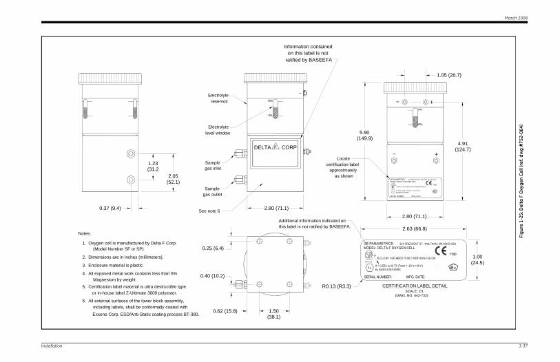
Notes:
1. Oxygen cell is manufactured by Delta F Corp.(Model Number SF or SP)
2. Dimensions are in inches (millimeters).
DELTA CORPF
apgas inlet
3. Enclosure material is plastic.
4. All exposed metal work contains less than 6%Magnesium by weight.
5. Certification label material is ultra destructible type
Information containedon this label is not
ratified by BASEEFA
certi
Additional information indicatthis label is not ratified by BA
or in-house label Z-Ultimate 3000 polyester.R0.13
See note 6
6. All external surfaces of the lower block assembly,including labels, shall be conformally coated withExxene Corp. ESD/Anti-Static coating process BT-380.
0.25 (6.4)
0.40 (10.2)
2.80 (71.1)
0.62 (15.8) 1.50(38.1)
0.37 (9.4)
1.23(31.2
2.05(52.1)
March 2008
1-38
ES 9, 10, 11, 13, 14
MMS 3
SEE NOTE 1
Figu
re 1
-26:
Moi
stur
e M
onit
or M
MS-
3 In
trin
sica
lly S
afe
Dia
gram
(ref
. dw
g #
752-
138,
sht
3)
Installation
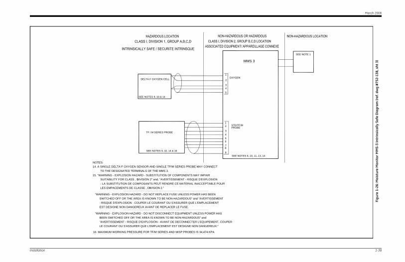
TF / M SERIES PROBE
LE COURANT OU S'ASSURER QUE L'EMPLACEMENT EST DESIGNE NON DANGEREUX.""AVERTISSEMENT - RISQUE D'EXPLOSION - AVANT DE DECONNECTER L'EQUIPEMENT, COUPER
"WARNING - EXPLOSION HAZARD - DO NOT DISCONNECT EQUIPMENT UNLESS POWER HAS BEEN SWITCHED OFF OR THE AREA IS KNOWN TO BE NON-HAZARDOUS" and
SWITCHED OFF OR THE AREA IS KNOWN TO BE NON-HAZARDOUS" and "AVERTISSEMENT "WARNING - EXPLOSION HAZARD - DO NOT REPLACE FUSE UNLESS POWER HAS BEEN
- RISQUE D'EXPLOSION - COUPER LE COURANT OU S'ASSURER QUE L'EMPLACEMENT EST DESIGNE NON DANGEREUX AVANT DE REPLACER LE FUSE.
LES EMPACEMENTS DE CLASSE , DIVISION 2."- LA SUBSTITUTION DE COMPOSANTS PEUT RENDRE CE MATERIAL INACCEPTABLE POUR
15. "WARNING - EXPLOSION HAZARD - SUBSTITUTION OF COMPONENTS MAY IMPAIRSUITABILITY FOR CLASS , DIVISION 2" and, "AVERTISSEMENT - RISQUE D'EXPLOSION
TO THE DESIGNATED TERMINALS OF THE MMS 3.14. A SINGLE DELTA F OXYGEN SENSOR AND SINGLE TF/M SERIES PROBE MAY CONNECT NOTES:
I
I
SEE NOT
STD/TF/MPROBE
7
9
8
65
2
34
1
DELTA F OXYGEN CELL
SEE NOTES 9, 10 & 14
OXYGEN
543
2
1
SEE NOTES 9, 10, 14 & 16
16. MAXIMUM WORKING PRESSURE FOR TF/M SERIES AND MISP PROBES IS 34,474 KPA

Chapter 2
Initial Setup
Startup Procedure . . . . . . . . . . . . . . . . . . . . . . . . . . . . . . . . . . . . . . . . . . . . . . 2-1
Displaying Measurements . . . . . . . . . . . . . . . . . . . . . . . . . . . . . . . . . . . . . . . 2-3
Adjusting the Screen Contrast . . . . . . . . . . . . . . . . . . . . . . . . . . . . . . . . . . . 2-6
March 2008
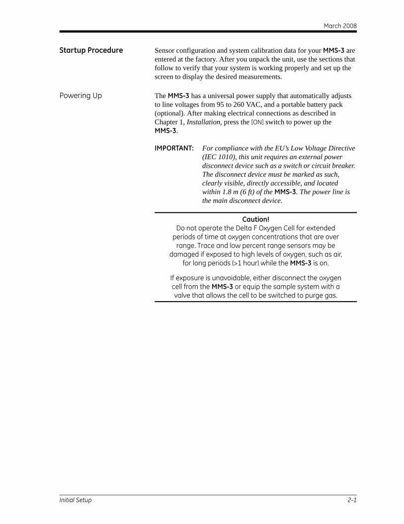
Startup Procedure Sensor configuration and system calibration data for your MMS-3 are entered at the factory. After you unpack the unit, use the sections that follow to verify that your system is working properly and set up the screen to display the desired measurements.
Powering Up The MMS-3 has a universal power supply that automatically adjusts to line voltages from 95 to 260 VAC, and a portable battery pack (optional). After making electrical connections as described in Chapter 1, Installation, press the [ON] switch to power up the MMS-3.
IMPORTANT: For compliance with the EU’s Low Voltage Directive (IEC 1010), this unit requires an external power disconnect device such as a switch or circuit breaker. The disconnect device must be marked as such, clearly visible, directly accessible, and located within 1.8 m (6 ft) of the MMS-3. The power line is the main disconnect device.
Caution!Do not operate the Delta F Oxygen Cell for extended
periods of time at oxygen concentrations that are over range. Trace and low percent range sensors may be
damaged if exposed to high levels of oxygen, such as air, for long periods (>1 hour) while the MMS-3 is on.
If exposure is unavoidable, either disconnect the oxygen cell from the MMS-3 or equip the sample system with a valve that allows the cell to be switched to purge gas.
Initial Setup 2-1
March 2008
Using the Keypad and Passcode
Use the following sections to become familiar with the key functions and discover the passcode number you will need to access the user program.
Key Functions The function keys to the right of the keypad are used in the following manner:
• [MODE] - modifies or selects the measurement mode to display.
• [CHAN] - toggles between channels (only works with units that have two channels installed).
• [PROG] - accesses the user program.
• [RUN] - exits the Modify Display Mode or the user program (except during numeric entry) and returns to displaying measurements.
The keypad beneath the MMS-3 screen consists of 16 keys, including the [.] and [–] symbols, two arrow keys, and two response keys, ([YES] and [NO]). The numeric keys are for numeric entry only; however, the arrow and response keys have more than one function.
The arrow keys perform three functions:
• arrow keys - scroll through the screen selections by moving the brackets forward or backward to the desired location.
• left arrow key - moves backward and erases during numeric entry.
• right arrow key - moves the cursor to the desired location during numeric entry and accepts a change at the present location.
The response keys perform three functions:
• [YES] or [NO] - respond to questions and/or exit a screen.
• [YES] - confirms an entry or retrieves a previously erased number.
• [NO] - moves backward through the menu.
IMPORTANT: After pressing a key, wait for the unit to perform the desired function before executing another key function.
Passcode To enter the user program you must enter a passcode. The passcode prevents unauthorized users from changing data. When entering the user program, the MMS-3 prompts for the passcode. Refer to the end of this chapter for your default passcode.
2-2 Initial Setup
March 2008
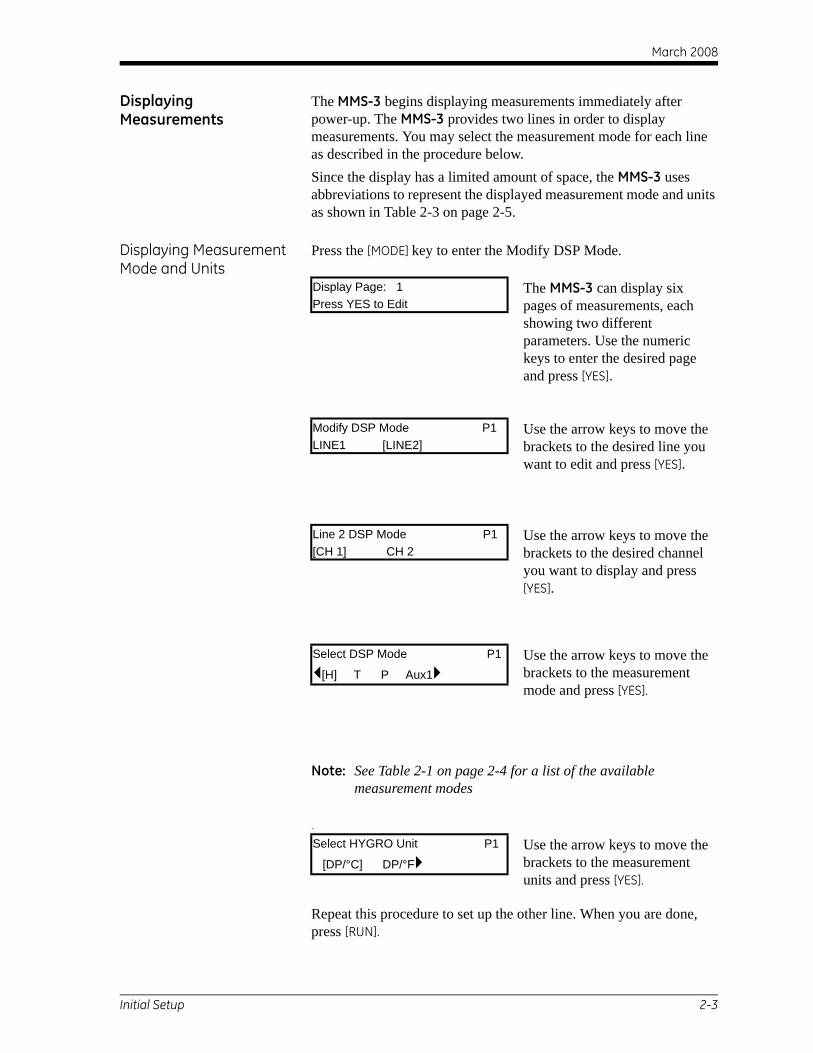
Displaying Measurements
The MMS-3 begins displaying measurements immediately after power-up. The MMS-3 provides two lines in order to display measurements. You may select the measurement mode for each line as described in the procedure below.Since the display has a limited amount of space, the MMS-3 uses abbreviations to represent the displayed measurement mode and units as shown in Table 2-3 on page 2-5.
Displaying Measurement Mode and Units
Press the [MODE] key to enter the Modify DSP Mode.
Note: See Table 2-1 on page 2-4 for a list of the available measurement modes
.
Repeat this procedure to set up the other line. When you are done, press [RUN].
Display Page: 1 The MMS-3 can display six pages of measurements, each showing two different parameters. Use the numeric keys to enter the desired page and press [YES].
Press YES to Edit
Modify DSP Mode P1 Use the arrow keys to move the brackets to the desired line you want to edit and press [YES].
LINE1 [LINE2]
Line 2 DSP Mode P1 Use the arrow keys to move the brackets to the desired channel you want to display and press [YES].
[CH 1] CH 2
Select DSP Mode P1 Use the arrow keys to move the brackets to the measurement mode and press [YES].
[H] T P Aux1
Select HYGRO Unit P1 Use the arrow keys to move the brackets to the measurement units and press [YES].
[DP/°C] DP/°F
Initial Setup 2-3
March 2008
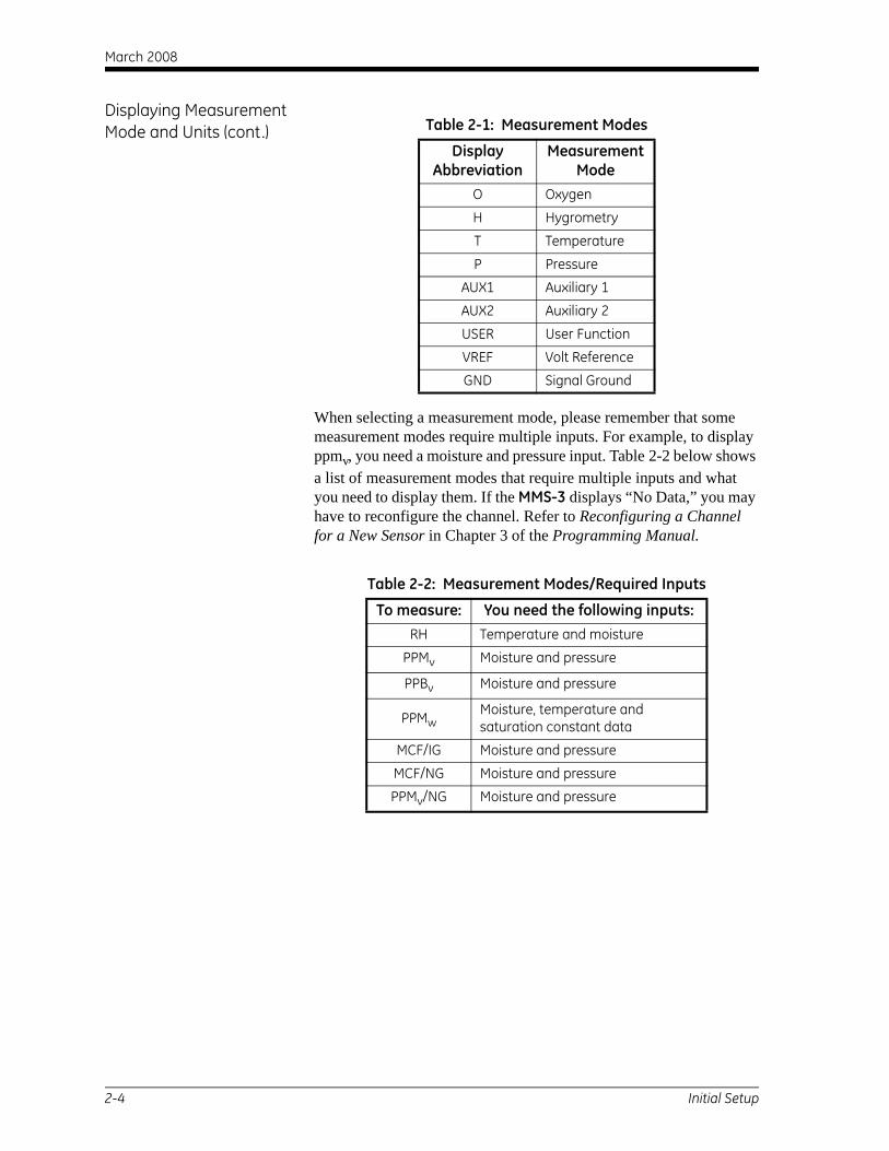
Displaying Measurement Mode and Units (cont.)
When selecting a measurement mode, please remember that some measurement modes require multiple inputs. For example, to display ppmv, you need a moisture and pressure input. Table 2-2 below shows a list of measurement modes that require multiple inputs and what you need to display them. If the MMS-3 displays “No Data,” you may have to reconfigure the channel. Refer to Reconfiguring a Channel for a New Sensor in Chapter 3 of the Programming Manual.
Table 2-1: Measurement Modes
Display Abbreviation
Measurement Mode
O Oxygen
H Hygrometry
T Temperature
P Pressure
AUX1 Auxiliary 1
AUX2 Auxiliary 2
USER User Function
VREF Volt Reference
GND Signal Ground
Table 2-2: Measurement Modes/Required Inputs
To measure: You need the following inputs:RH Temperature and moisture
PPMv Moisture and pressure
PPBv Moisture and pressure
PPMwMoisture, temperature andsaturation constant data
MCF/IG Moisture and pressure
MCF/NG Moisture and pressure
PPMv/NG Moisture and pressure
2-4 Initial Setup
March 2008
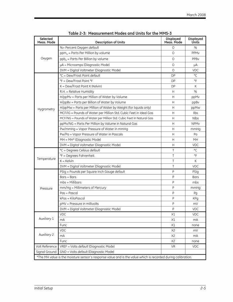
Table 2-3: Measurement Modes and Units for the MMS-3Selected
Meas. Mode Description of UnitsDisplayed
Meas. ModeDisplayed
Units
Oxygen
%= Percent Oxygen default O %ppmv = Parts Per Million by volume O PPMv
ppbv = Parts Per Billion by volume O PPBv
µA = Microamps (Diagnostic Mode) O µA
DVM = Digital Voltmeter (Diagnostic Mode) O VDC
Hygrometry
°C = Dew/Frost Point default DP °C°F = Dew/Frost Point °F DP °F
K = Dew/Frost Point K (Kelvin) DP KR.H. = Relative Humidity H %H/ppMv = Parts per Million of Water by Volume H ppMv
H/ppBv = Parts per Billion of Water by Volume H ppBvH/ppMw = Parts per Million of Water by Weight (for liquids only) H ppMwMCF/IG = Pounds of Water per Million Std. Cubic Feet in Ideal Gas H IlbsMCF/NG = Pounds of Water per Million Std. Cubic Feet in Natural Gas H NlbsppMv/NG = Parts Per Million by Volume in Natural Gas H NPMvPw/mmHg = Vapor Pressure of Water in mmHg H mmHg
Pw/Pa = Vapor Pressure of Water in Pascals H PaMH = MH* (Diagnostic Mode) H MHDVM = Digital Voltmeter (Diagnostic Mode) H VDC
Temperature
°C = Degrees Celsius default T °C°F = Degrees Fahrenheit T °FK = Kelvin T K
DVM = Digital Voltmeter (Diagnostic Mode) T VDC
Pressure
PSIg = Pounds per Square Inch Gauge default P PSIgBars = Bars P Bars
mbs = Millibars P mbsmm/Hg = Millimeters of Mercury P mmHgPas = Pascal P Pg
kPas = KiloPascal P KPgpMV = Pressure in millivolts P mVDVM = Digital Voltmeter (Diagnostic Mode) P VDC
Auxiliary 1VDC X1 VDCmA X1 mA Func X1 none
Auxiliary 2VDC X2 mVmA X2 mAFunc X2 none
Volt Reference VREF = Volts default (Diagnostic Mode) VR VDCSignal Ground GND = Volts default (Diagnostic Mode)
*The MH value is the moisture sensor’s response value and is the value which is recorded during calibration.
Initial Setup 2-5
March 2008
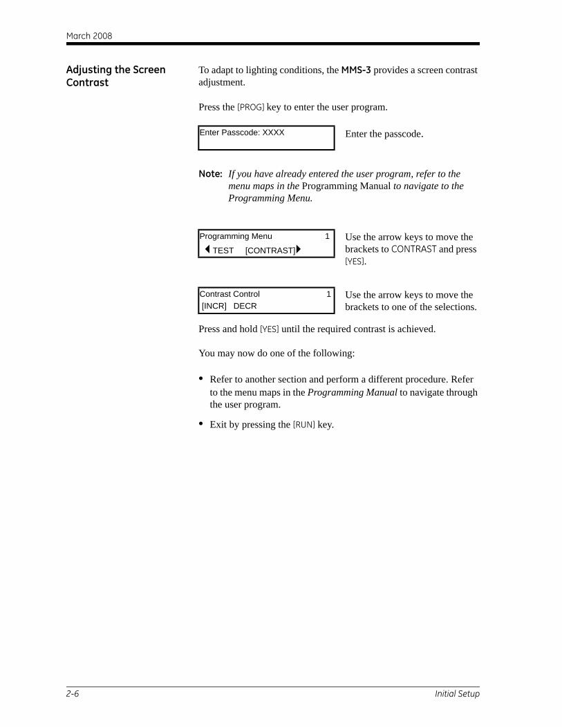
Adjusting the Screen Contrast
To adapt to lighting conditions, the MMS-3 provides a screen contrast adjustment.
Press the [PROG] key to enter the user program.
Note: If you have already entered the user program, refer to the menu maps in the Programming Manual to navigate to the Programming Menu.
Press and hold [YES] until the required contrast is achieved.
You may now do one of the following:
• Refer to another section and perform a different procedure. Refer to the menu maps in the Programming Manual to navigate through the user program.
• Exit by pressing the [RUN] key.
Enter Passcode: XXXX Enter the passcode.
Programming Menu 1 Use the arrow keys to move the brackets to CONTRAST and press [YES].
TEST [CONTRAST]
Contrast Control 1 Use the arrow keys to move the brackets to one of the selections. [INCR] DECR
2-6 Initial Setup

Your passcode is 2719.
Please remove this page and put it in a safe place for future reference.

Chapter 3
Specifications
Overall Specifications . . . . . . . . . . . . . . . . . . . . . . . . . . . . . . . . . . . . . . . . . . . 3-1
Moisture Measurement. . . . . . . . . . . . . . . . . . . . . . . . . . . . . . . . . . . . . . . . . . 3-2
Pressure Measurement . . . . . . . . . . . . . . . . . . . . . . . . . . . . . . . . . . . . . . . . . . 3-3
Temperature . . . . . . . . . . . . . . . . . . . . . . . . . . . . . . . . . . . . . . . . . . . . . . . . . . . 3-3
Oxygen Measurement . . . . . . . . . . . . . . . . . . . . . . . . . . . . . . . . . . . . . . . . . . . 3-3
Electronics . . . . . . . . . . . . . . . . . . . . . . . . . . . . . . . . . . . . . . . . . . . . . . . . . . . . . 3-4
Outputs. . . . . . . . . . . . . . . . . . . . . . . . . . . . . . . . . . . . . . . . . . . . . . . . . . . . . . . . 3-5
Inputs . . . . . . . . . . . . . . . . . . . . . . . . . . . . . . . . . . . . . . . . . . . . . . . . . . . . . . . . . 3-6
Probes . . . . . . . . . . . . . . . . . . . . . . . . . . . . . . . . . . . . . . . . . . . . . . . . . . . . . . . . . 3-7
Delta F Oxygen Cell . . . . . . . . . . . . . . . . . . . . . . . . . . . . . . . . . . . . . . . . . . . . . 3-9
March 2008
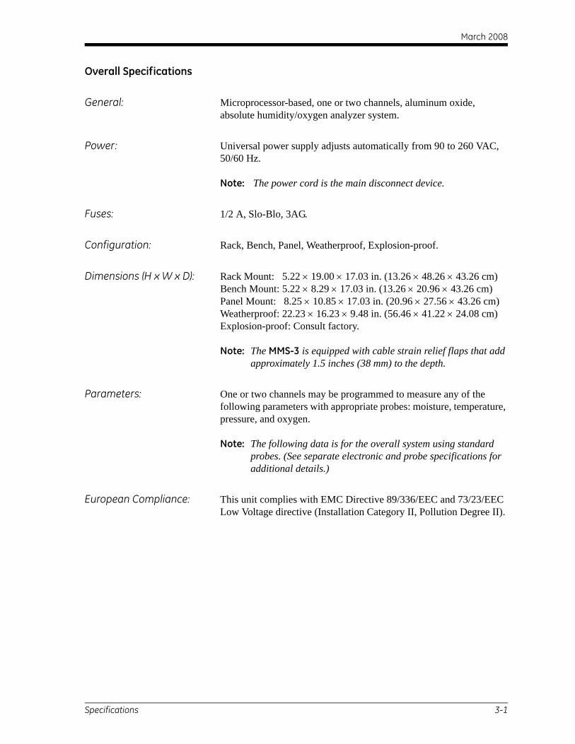
Overall Specifications
General: Microprocessor-based, one or two channels, aluminum oxide, absolute humidity/oxygen analyzer system.
Power: Universal power supply adjusts automatically from 90 to 260 VAC, 50/60 Hz.
Note: The power cord is the main disconnect device.
Fuses: 1/2 A, Slo-Blo, 3AG.
Configuration: Rack, Bench, Panel, Weatherproof, Explosion-proof.
Dimensions (H x W x D): Rack Mount: 5.22 × 19.00 × 17.03 in. (13.26 × 48.26 × 43.26 cm)Bench Mount: 5.22 × 8.29 × 17.03 in. (13.26 × 20.96 × 43.26 cm)Panel Mount: 8.25 × 10.85 × 17.03 in. (20.96 × 27.56 × 43.26 cm)Weatherproof: 22.23 × 16.23 × 9.48 in. (56.46 × 41.22 × 24.08 cm)Explosion-proof: Consult factory.
Note: The MMS-3 is equipped with cable strain relief flaps that add approximately 1.5 inches (38 mm) to the depth.
Parameters: One or two channels may be programmed to measure any of the following parameters with appropriate probes: moisture, temperature, pressure, and oxygen.
Note: The following data is for the overall system using standard probes. (See separate electronic and probe specifications for additional details.)
European Compliance: This unit complies with EMC Directive 89/336/EEC and 73/23/EEC Low Voltage directive (Installation Category II, Pollution Degree II).
Specifications 3-1
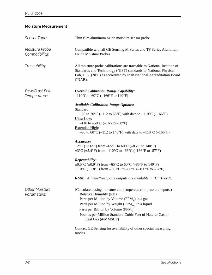
March 2008
Moisture Measurement
Sensor Type: Thin film aluminum oxide moisture sensor probe.
Moisture Probe Compatibility:
Compatible with all GE Sensing M Series and TF Series Aluminum Oxide Moisture Probes.
Traceability: All moisture probe calibrations are traceable to National Institute of Standards and Technology (NIST) standards or National Physical Lab, U.K. (NPL) as accredited by Irish National Accreditation Board (INAB).
Dew/Frost Point Temperature:
Overall Calibration Range Capability:–110°C to 60°C (–166°F to 140°F)
Available Calibration Range Options:Standard: –80 to 20°C (–112 to 68°F) with data to –110°C (–166°F)Ultra-Low: –110 to –50°C (–166 to –58°F)Extended High: –80 to 60°C (–112 to 140°F) with data to –110°C (–166°F)
Accuracy:±2°C (±3.6°F) from –65°C to 60°C (–85°F to 140°F) ±3°C (±5.4°F) from –110°C to –66°C (–166°F to -87°F)
Repeatability:±0.5°C (±0.9°F) from –65°C to 60°C (–85°F to 140°F) ±1.0°C (±1.8°F) from –110°C to –66°C (–166°F to –87°F)
Note: All dew/frost point outputs are available in °C, °F or K.
Other Moisture Parameters:
(Calculated using moisture and temperature or pressure inputs.) Relative Humidity (RH) Parts per Million by Volume (PPMv) in a gas Parts per Million by Weight (PPMw) in a liquid
Parts per Billion by Volume (PPMv) Pounds per Million Standard Cubic Feet of Natural Gas or Ideal Gas (#/MMSCF)
Contact GE Sensing for availability of other special measuring modes.
3-2 Specifications
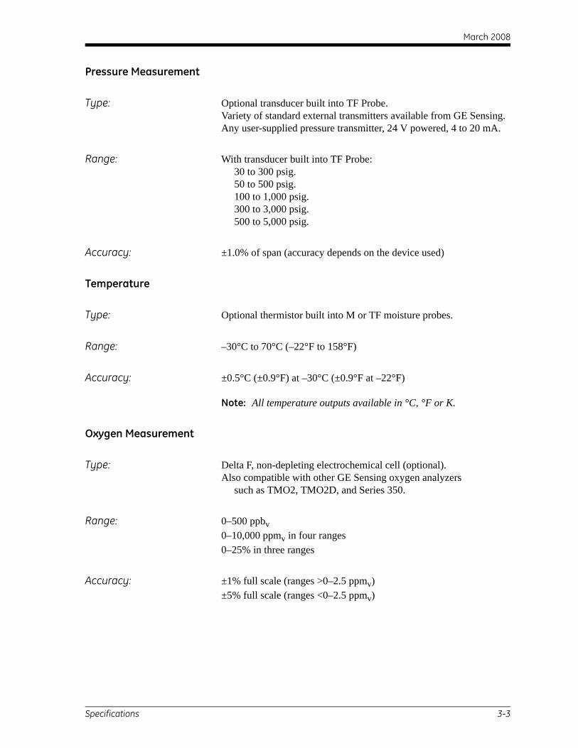
March 2008
Pressure Measurement
Type: Optional transducer built into TF Probe.Variety of standard external transmitters available from GE Sensing.Any user-supplied pressure transmitter, 24 V powered, 4 to 20 mA.
Range: With transducer built into TF Probe: 30 to 300 psig. 50 to 500 psig. 100 to 1,000 psig. 300 to 3,000 psig. 500 to 5,000 psig.
Accuracy: ±1.0% of span (accuracy depends on the device used)
Temperature
Type: Optional thermistor built into M or TF moisture probes.
Range: –30°C to 70°C (–22°F to 158°F)
Accuracy: ±0.5°C (±0.9°F) at –30°C (±0.9°F at –22°F)
Note: All temperature outputs available in °C, °F or K.
Oxygen Measurement
Type: Delta F, non-depleting electrochemical cell (optional).Also compatible with other GE Sensing oxygen analyzers such as TMO2, TMO2D, and Series 350.
Range: 0–500 ppbv0–10,000 ppmv in four ranges0–25% in three ranges
Accuracy: ±1% full scale (ranges >0–2.5 ppmv) ±5% full scale (ranges <0–2.5 ppmv)
Specifications 3-3
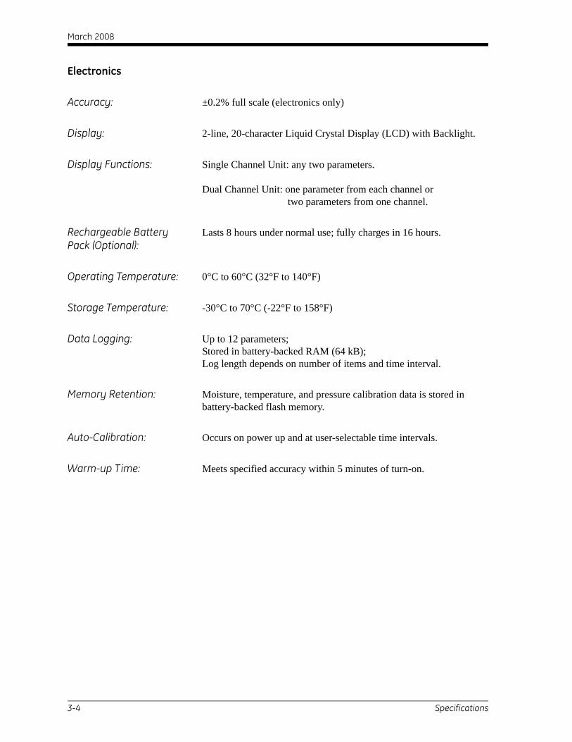
March 2008
Electronics
Accuracy: ±0.2% full scale (electronics only)
Display: 2-line, 20-character Liquid Crystal Display (LCD) with Backlight.
Display Functions: Single Channel Unit: any two parameters.
Dual Channel Unit: one parameter from each channel ortwo parameters from one channel.
Rechargeable Battery Pack (Optional):
Lasts 8 hours under normal use; fully charges in 16 hours.
Operating Temperature: 0°C to 60°C (32°F to 140°F)
Storage Temperature: -30°C to 70°C (-22°F to 158°F)
Data Logging: Up to 12 parameters;Stored in battery-backed RAM (64 kB);Log length depends on number of items and time interval.
Memory Retention: Moisture, temperature, and pressure calibration data is stored in battery-backed flash memory.
Auto-Calibration: Occurs on power up and at user-selectable time intervals.
Warm-up Time: Meets specified accuracy within 5 minutes of turn-on.
3-4 Specifications
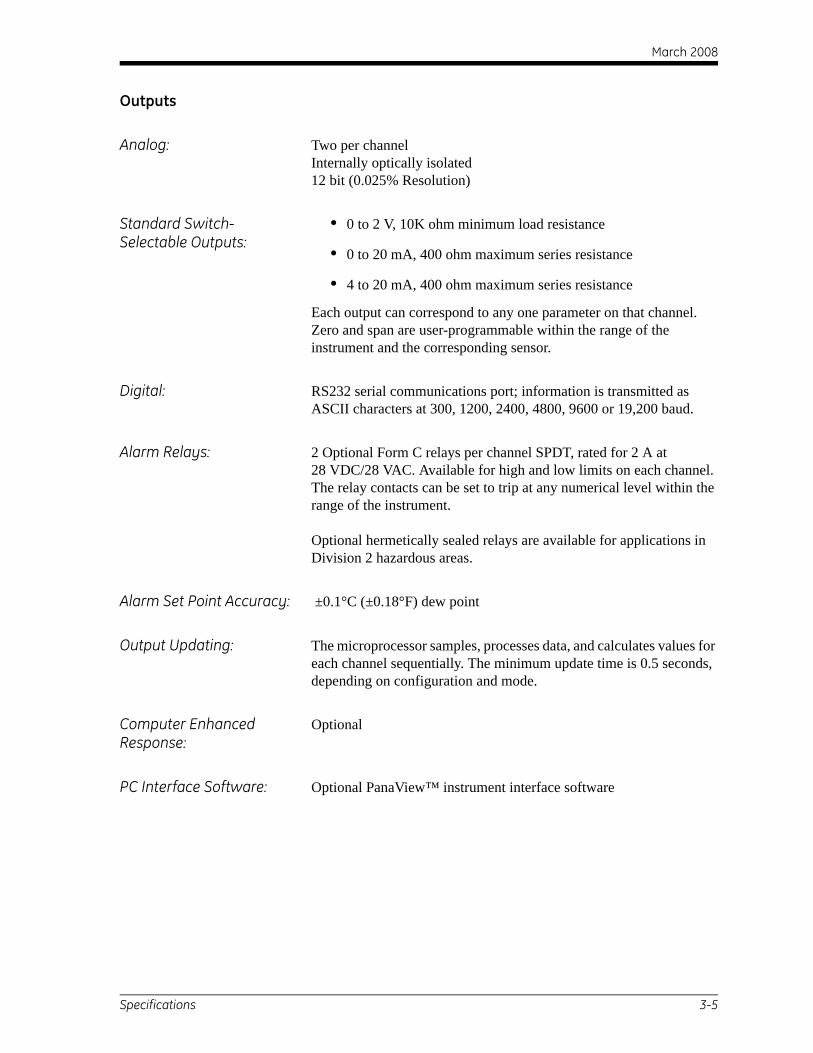
March 2008
Outputs
Analog: Two per channel Internally optically isolated12 bit (0.025% Resolution)
Standard Switch-Selectable Outputs:
• 0 to 2 V, 10K ohm minimum load resistance
• 0 to 20 mA, 400 ohm maximum series resistance
• 4 to 20 mA, 400 ohm maximum series resistance
Each output can correspond to any one parameter on that channel. Zero and span are user-programmable within the range of the instrument and the corresponding sensor.
Digital: RS232 serial communications port; information is transmitted as ASCII characters at 300, 1200, 2400, 4800, 9600 or 19,200 baud.
Alarm Relays: 2 Optional Form C relays per channel SPDT, rated for 2 A at28 VDC/28 VAC. Available for high and low limits on each channel. The relay contacts can be set to trip at any numerical level within the range of the instrument.
Optional hermetically sealed relays are available for applications in Division 2 hazardous areas.
Alarm Set Point Accuracy: ±0.1°C (±0.18°F) dew point
Output Updating: The microprocessor samples, processes data, and calculates values for each channel sequentially. The minimum update time is 0.5 seconds, depending on configuration and mode.
Computer Enhanced Response:
Optional
PC Interface Software: Optional PanaView™ instrument interface software
Specifications 3-5
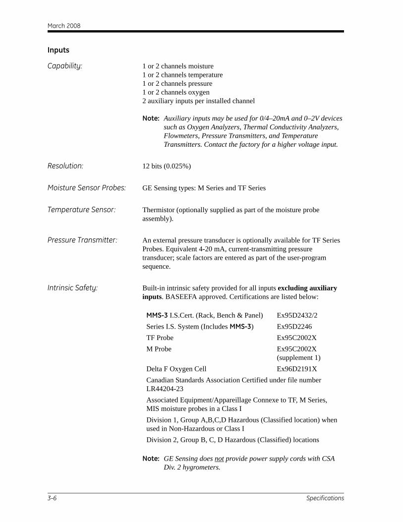
March 2008
Inputs
Capability: 1 or 2 channels moisture1 or 2 channels temperature1 or 2 channels pressure1 or 2 channels oxygen2 auxiliary inputs per installed channel
Note: Auxiliary inputs may be used for 0/4–20mA and 0–2V devices such as Oxygen Analyzers, Thermal Conductivity Analyzers, Flowmeters, Pressure Transmitters, and Temperature Transmitters. Contact the factory for a higher voltage input.
Resolution: 12 bits (0.025%)
Moisture Sensor Probes: GE Sensing types: M Series and TF Series
Temperature Sensor: Thermistor (optionally supplied as part of the moisture probe assembly).
Pressure Transmitter: An external pressure transducer is optionally available for TF Series Probes. Equivalent 4-20 mA, current-transmitting pressure transducer; scale factors are entered as part of the user-program sequence.
Intrinsic Safety: Built-in intrinsic safety provided for all inputs excluding auxiliary inputs. BASEEFA approved. Certifications are listed below:
Note: GE Sensing does not provide power supply cords with CSA Div. 2 hygrometers.
MMS-3 I.S.Cert. (Rack, Bench & Panel) Ex95D2432/2Series I.S. System (Includes MMS-3) Ex95D2246TF Probe Ex95C2002XM Probe Ex95C2002X
(supplement 1)Delta F Oxygen Cell Ex96D2191XCanadian Standards Association Certified under file number LR44204-23Associated Equipment/Appareillage Connexe to TF, M Series, MIS moisture probes in a Class IDivision 1, Group A,B,C,D Hazardous (Classified location) when used in Non-Hazardous or Class IDivision 2, Group B, C, D Hazardous (Classified) locations
3-6 Specifications
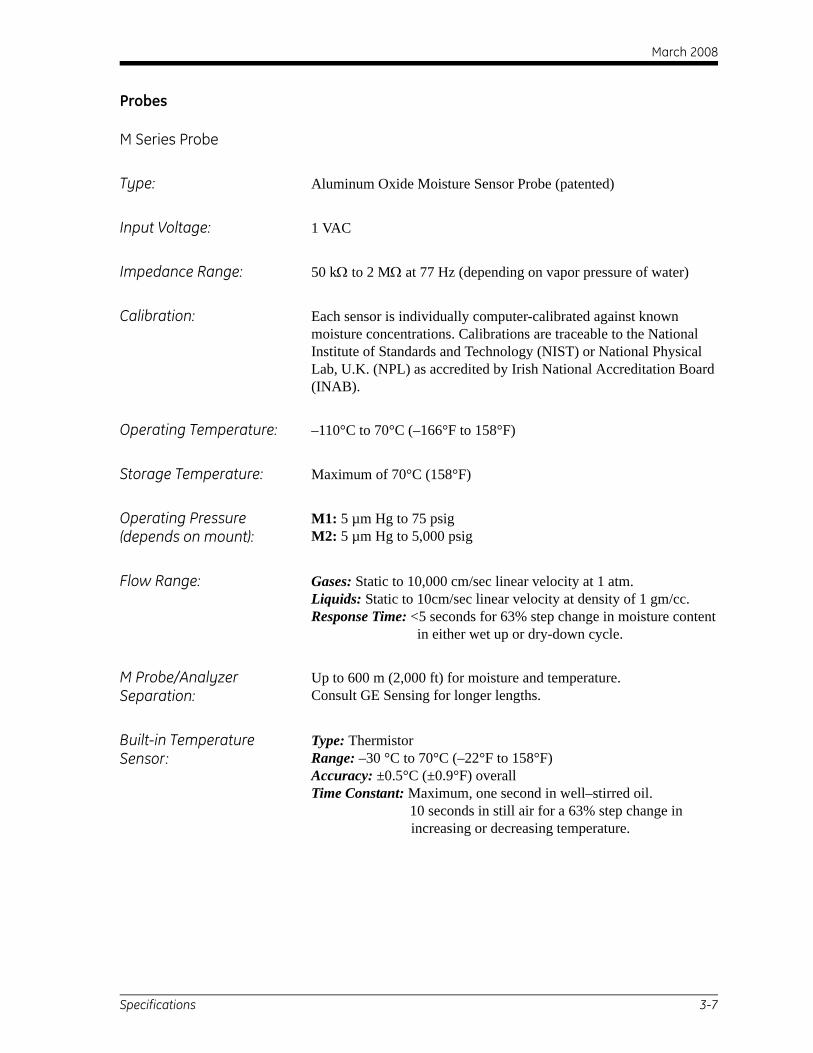
March 2008
Probes
M Series Probe
Type: Aluminum Oxide Moisture Sensor Probe (patented)
Input Voltage: 1 VAC
Impedance Range: 50 kΩ to 2 MΩ at 77 Hz (depending on vapor pressure of water)
Calibration: Each sensor is individually computer-calibrated against known moisture concentrations. Calibrations are traceable to the National Institute of Standards and Technology (NIST) or National Physical Lab, U.K. (NPL) as accredited by Irish National Accreditation Board (INAB).
Operating Temperature: –110°C to 70°C (–166°F to 158°F)
Storage Temperature: Maximum of 70°C (158°F)
Operating Pressure (depends on mount):
M1: 5 µm Hg to 75 psigM2: 5 µm Hg to 5,000 psig
Flow Range: Gases: Static to 10,000 cm/sec linear velocity at 1 atm. Liquids: Static to 10cm/sec linear velocity at density of 1 gm/cc. Response Time: <5 seconds for 63% step change in moisture content in either wet up or dry-down cycle.
M Probe/Analyzer Separation:
Up to 600 m (2,000 ft) for moisture and temperature.Consult GE Sensing for longer lengths.
Built-in Temperature Sensor:
Type: ThermistorRange: –30 °C to 70°C (–22°F to 158°F)Accuracy: ±0.5°C (±0.9°F) overallTime Constant: Maximum, one second in well–stirred oil. 10 seconds in still air for a 63% step change in
increasing or decreasing temperature.
Specifications 3-7
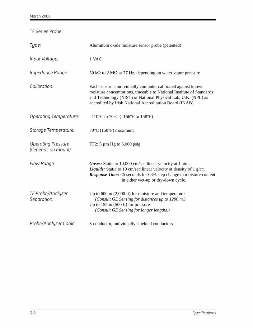
March 2008
TF Series Probe
Type: Aluminum oxide moisture sensor probe (patented)
Input Voltage: 1 VAC
Impedance Range: 50 kΩ to 2 MΩ at 77 Hz, depending on water vapor pressure
Calibration: Each sensor is individually computer calibrated against known moisture concentrations, traceable to National Institute of Standards and Technology (NIST) or National Physical Lab, U.K. (NPL) as accredited by Irish National Accreditation Board (INAB).
Operating Temperature: –110°C to 70°C (–166°F to 158°F)
Storage Temperature: 70°C (158°F) maximum
Operating Pressure (depends on mount):
TF2: 5 µm Hg to 5,000 psig
Flow Range: Gases: Static to 10,000 cm/sec linear velocity at 1 atm.Liquids: Static to 10 cm/sec linear velocity at density of 1 g/cc.Response Time: <5 seconds for 63% step change in moisture content
in either wet-up or dry-down cycle.
TF Probe/Analyzer Separation:
Up to 600 m (2,000 ft) for moisture and temperature (Consult GE Sensing for distances up to 1200 m.)Up to 152 m (500 ft) for pressure (Consult GE Sensing for longer lengths.)
Probe/Analyzer Cable: 8-conductor, individually shielded conductors
3-8 Specifications
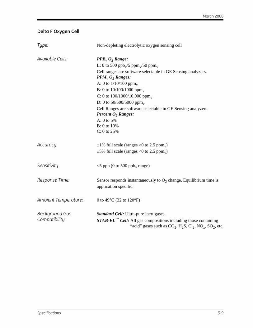
March 2008
Delta F Oxygen Cell
Type: Non-depleting electrolytic oxygen sensing cell
Available Cells: PPBv O2 Range:L: 0 to 500 ppbv/5 ppmv/50 ppmvCell ranges are software selectable in GE Sensing analyzers.PPMv O2 Ranges:A: 0 to 1/10/100 ppmvB: 0 to 10/100/1000 ppmvC: 0 to 100/1000/10,000 ppmvD: 0 to 50/500/5000 ppmvCell Ranges are software selectable in GE Sensing analyzers.Percent O2 Ranges:A: 0 to 5%B: 0 to 10%C: 0 to 25%
Accuracy: ±1% full scale (ranges >0 to 2.5 ppmv)±5% full scale (ranges <0 to 2.5 ppmv)
Sensitivity: <5 ppb (0 to 500 ppbv range)
Response Time: Sensor responds instantaneously to O2 change. Equilibrium time is application specific.
Ambient Temperature: 0 to 49°C (32 to 120°F)
Background Gas Compatibility:
Standard Cell: Ultra-pure inert gases.STAB-EL™ Cell: All gas compositions including those containing “acid” gases such as CO2, H2S, Cl2, NOx, SO2, etc.
Specifications 3-9
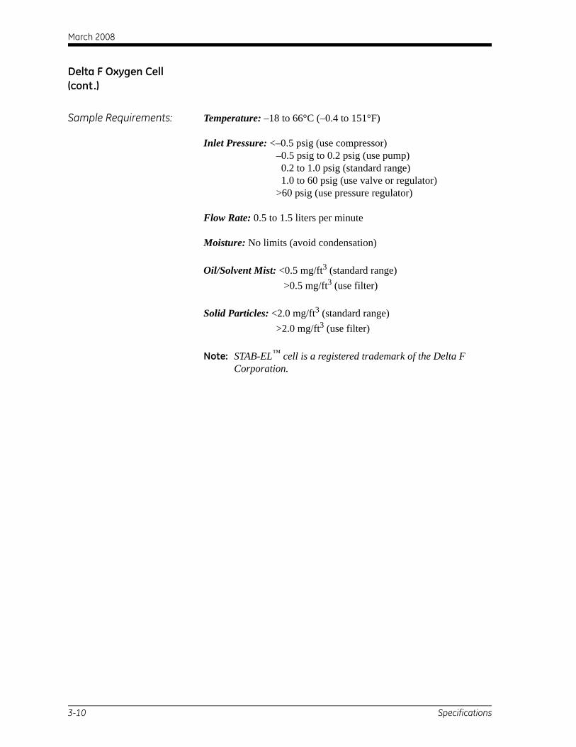
March 2008
Delta F Oxygen Cell (cont.)
Sample Requirements: Temperature: –18 to 66°C (–0.4 to 151°F)
Inlet Pressure: <–0.5 psig (use compressor) –0.5 psig to 0.2 psig (use pump) 0.2 to 1.0 psig (standard range) 1.0 to 60 psig (use valve or regulator) >60 psig (use pressure regulator)
Flow Rate: 0.5 to 1.5 liters per minute
Moisture: No limits (avoid condensation)
Oil/Solvent Mist: <0.5 mg/ft3 (standard range) >0.5 mg/ft3 (use filter)
Solid Particles: <2.0 mg/ft3 (standard range) >2.0 mg/ft3 (use filter)
Note: STAB-EL™ cell is a registered trademark of the Delta F Corporation.
3-10 Specifications
March 2008
Index
AAdjusting Screen Contrast . . . . . . . . . . . . . . . 2-6Arrow Key Functions. . . . . . . . . . . . . . . . . . . 2-2
CCables
Acceptable Lengths for . . . . . . . . . . . . . . 1-25Error . . . . . . . . . . . . . . . . . . . . . . . . . . . . . 1-25
ConnectionsElectrical . . . . . . . . . . . . . . . . . . . . . . . . . 1-18
Contrast, Adjusting . . . . . . . . . . . . . . . . . . . . 2-6
DDelta F Oxygen Cell Specifications. . . . . . . . 3-9Displaying Measurements . . . . . . . . . . . . . . . 2-3
EElectrical Connections . . . . . . . . . . . . . . . . . 1-18
M Series Probe . . . . . . . . . . . . . . . . . . . . . 1-21Oxygen Cell . . . . . . . . . . . . . . . . . . . . . . . 1-25TF Series Probe . . . . . . . . . . . . . . . . . . . . 1-23
Electrolyte, in Oxygen Cell . . . . . . . . 1-16, 1-17Electronics Specifications . . . . . . . . . . . . . . . 3-4Electronics Unit, Mounting . . . . . . . . . . . . . 1-12
GGas Flow for Oxygen Cell . . . . . . . . . . . . . . 1-30Getting Started . . . . . . . . . . . . . . . . . . . . . . . . 2-1
IInputs Specifications . . . . . . . . . . . . . . . . . . . 3-6Installation
Electronics Unit . . . . . . . . . . . . . . . . . . . . 1-12Gas Flow for Oxygen Cell . . . . . . . . . . . . 1-30Moisture Probes . . . . . . . . . . . . . . . . . . . . . 1-6Oxygen Cell into Sample System . . . . . . 1-15Pressure Transmitter. . . . . . . . . . . . . . . . . 1-14Probes into Sample System . . . . . . . . . . . 1-13Sample System . . . . . . . . . . . . . . . . . 1-8, 1-12Site Selection . . . . . . . . . . . . . . . . . . . . . . . 1-4
KKeypad
Arrow Keys . . . . . . . . . . . . . . . . . . . . . . . . .2-2Response Keys . . . . . . . . . . . . . . . . . . . . . .2-2YES and NO Keys . . . . . . . . . . . . . . . . . . .2-2
MM Series Probe
Connecting . . . . . . . . . . . . . . . . . . . 1-20, 1-21Installation into Sample System . . . . . . . .1-13Specifications . . . . . . . . . . . . . . . . . . . . . . .3-7
Measurements, Displaying . . . . . . . . . . . . . . .2-3Moisture Measurement Specifications . . . . . .3-2Moisture Probes
Installation. . . . . . . . . . . . . . . . . . . . . . . . . .1-6Installation into Sample System . . . . . . . .1-13Sample System . . . . . . . . . . . . . . . . . . . . . .1-8
MountingElectronics Unit . . . . . . . . . . . . . . . . . . . .1-12Sample System . . . . . . . . . . . . . . . . . . . . .1-12
NNO Key Functions . . . . . . . . . . . . . . . . . . . . .2-2
OOutputs Specifications . . . . . . . . . . . . . . . . . .3-5Oxygen Cell
Adding Electrolyte . . . . . . . . . . . . . 1-16, 1-17Connecting . . . . . . . . . . . . . . . . . . . . . . . .1-25Establishing a Gas Flow . . . . . . . . . . . . . .1-30Initial Checkout. . . . . . . . . . . . . . . . . . . . . .1-2Installation into Sample System . . . . . . . .1-15Preparing . . . . . . . . . . . . . . . . . . . . . 1-16, 1-17Sample System . . . . . . . . . . . . . . . . . . . . . .1-8
Oxygen Measurement Specifications . . . . . . .3-3
PPasscode . . . . . . . . . . . . . . . . . . . . . . . . . . . . .2-2Pressure Measurement Specifications. . . . . . .3-3Pressure Transmitter
Installation into Sample System . . . . . . . .1-14Probes
Installation into Sample System . . . . . . . .1-13Installing Pressure Transmitter . . . . . . . . .1-14Specifications . . . . . . . . . . . . . . . . . . . . . . .3-7
Index 1

March 2008
Index (cont.)
RResponse Key Functions. . . . . . . . . . . . . . . . . 2-2
SSafety, Initial Checkout . . . . . . . . . . . . . . . . . 1-2Sample System
Description . . . . . . . . . . . . . . . . . . . . . . . . . 1-8Installing Oxygen Cell . . . . . . . . . . . . . . . 1-15Installing Pressure Transmitter . . . . . . . . . 1-14Installing Probes . . . . . . . . . . . . . . . . . . . . 1-13Mounting. . . . . . . . . . . . . . . . . . . . . . . . . . 1-12
Screen, Adjusting Contrast . . . . . . . . . . . . . . . 2-6Site Selection . . . . . . . . . . . . . . . . . . . . . . . . . 1-4Specifications
Delta F Oxygen Cell . . . . . . . . . . . . . . . . . . 3-9Electronics . . . . . . . . . . . . . . . . . . . . . . . . . 3-4Inputs . . . . . . . . . . . . . . . . . . . . . . . . . . . . . 3-6M Series Probe . . . . . . . . . . . . . . . . . . . . . . 3-7Moisture Measurement . . . . . . . . . . . . . . . . 3-2Outputs . . . . . . . . . . . . . . . . . . . . . . . . . . . . 3-5Overall . . . . . . . . . . . . . . . . . . . . . . . . . . . . 3-1Oxygen Measurement . . . . . . . . . . . . . . . . . 3-3Pressure Measurement . . . . . . . . . . . . . . . . 3-3Probes . . . . . . . . . . . . . . . . . . . . . . . . . . . . . 3-7Temperature . . . . . . . . . . . . . . . . . . . . . . . . 3-3TF Series Probe. . . . . . . . . . . . . . . . . . . . . . 3-8
TTemperature Specifications . . . . . . . . . . . . . . 3-3TF Series Probe
Connecting . . . . . . . . . . . . . . . . . . . . . . . . 1-23Installation into Sample System . . . . . . . . 1-13Specifications . . . . . . . . . . . . . . . . . . . . . . . 3-8
UUnpacking. . . . . . . . . . . . . . . . . . . . . . . . . . . . 1-1
YYES Key Functions . . . . . . . . . . . . . . . . . . . . 2-2
2 Index

CERT-ATEX-D (Rev. August 2004)
GE InfrastructureSensing ATEX COMPLIANCE
We, GE Infrastructure Sensing, Inc. 1100 Technology Park Drive
Billerica, MA 01821-4111 U.S.A.
as the manufacturer, declare under our sole responsibility that the product
Moisture Monitor Series 3 Analyzer
to which this document relates, in accordance with the provisions of ATEX Directive 94/9/EC Annex II, meets the following specifications:
Furthermore, the following additional requirements and specifications apply to the product:
• Having been designed in accordance with EN 50014 and EN 50020, the product meets the fault tolerance requirements of electrical apparatus for category “ia”.
• The product is an electrical apparatus and must be installed in the hazardous area in accordance with the requirements of the EC Type Examination Certificate. The installation must be carried out in accordance with all appropriate international, national and local standard codes and practices and site regulations for flameproof apparatus and in accordance with the instructions contained in the manual. Access to the circuitry must not be made during operation.
• Only trained, competent personnel may install, operate and maintain the equipment.
• The product has been designed so that the protection afforded will not be reduced due to the effects of corrosion of materials, electrical conductivity, impact strength, aging resistance or the effects of temperature variations.
• The product cannot be repaired by the user; it must be replaced by an equivalent certified product. Repairs should only be carried out by the manufacturer or by an approved repairer.
• The product must not be subjected to mechanical or thermal stresses in excess of those permitted in the certification documentation and the instruction manual.
• The product contains no exposed parts which produce surface temperature infrared, electromagnetic ionizing, or non-electrical dangers.
1180
II 1 G EEx ia IIC (-20°C to +50°C)BAS01ATEX7097

GE InfrastructureSensing
DECLARATIONOF
CONFORMITY
CERT-DOC-H2 August 2004
TÜV ESSENISO 9001
U.S.
TÜV
We, Panametrics Limited Shannon Industrial Estate
Shannon, County Clare Ireland
declare under our sole responsibility that the
Moisture Image Series 1 AnalyzerMoisture Image Series 2 Analyzer
Moisture Monitor Series 3 Analyzer
to which this declaration relates, are in conformity with the following standards:
• EN 50014:1997+A1+A2:1999
• EN 50020:1994
• II (1) G [EEx ia] IICBAS01ATEX7097Baseefa (2001) Ltd/EECS, Buxton SK17 9JN, UK
• EN 61326:1998, Class A, Annex A, Continuous Unmonitored Operation
• EN 61010-1:1993+A2:1995, Overvoltage Category II, Pollution Degree 2
following the provisions of the 89/336/EEC EMC Directive, the 73/23/EEC Low Voltage Directive and the 94/9/EC ATEX Directive.
The units listed above and any sensors and ancillary sample handling systems supplied with them do not bear CE marking for the Pressure Equipment Directive, as they are supplied in accordance with Article 3, Section 3 (sound engineering practices and codes of good workmanship) of the Pressure Equipment Directive 97/23/EC for DN<25.
Shannon - July 1, 2003Mr. James Gibson
GENERAL MANAGER

GE InfrastructureSensing
DECLARATIONDE
CONFORMITE
CERT-DOC-H2 August 2004
TÜV ESSENISO 9001
U.S.
TÜV
Nous, Panametrics Limited Shannon Industrial Estate
Shannon, County Clare Ireland
déclarons sous notre propre responsabilité que les
Moisture Image Series 1 AnalyzerMoisture Image Series 2 Analyzer
Moisture Monitor Series 3 Analyzer
rélatif á cette déclaration, sont en conformité avec les documents suivants:
• EN 50014:1997+A1+A2:1999
• EN 50020:1994
• II (1) G [EEx ia] IICBAS01ATEX7097Baseefa (2001) Ltd/EECS, Buxton SK17 9JN, UK
• EN 61326:1998, Class A, Annex A, Continuous Unmonitored Operation
• EN 61010-1:1993+A2:1995, Overvoltage Category II, Pollution Degree 2
suivant les régles de la Directive de Compatibilité Electromagnétique 89/336/EEC, de la Directive Basse Tension73/23/EEC et d’ATEX 94/9/EC.
Les matériels listés ci-dessus, ainsi que les capteurs et les systèmes d'échantillonnages pouvant être livrés avec ne portent pas le marquage CE de la directive des équipements sous pression, car ils sont fournis en accord avec la directive 97/23/EC des équipements sous pression pour les DN<25, Article 3, section 3 qui concerne les pratiques et les codes de bonne fabrication pour l'ingénierie du son.
Shannon - July 1, 2003Mr. James Gibson
DIRECTEUR GÉNÉRAL

GE InfrastructureSensing KONFORMITÄTS-
ERKLÄRUNG
CERT-DOC-H2 August 2004
TÜV ESSENISO 9001
U.S.
TÜV
Wir, Panametrics Limited Shannon Industrial Estate
Shannon, County Clare Ireland
erklären, in alleiniger Verantwortung, daß die Produkte
Moisture Image Series 1 AnalyzerMoisture Image Series 2 Analyzer
Moisture Monitor Series 3 Analyzer
folgende Normen erfüllen:
• EN 50014:1997+A1+A2:1999
• EN 50020:1994
• II (1) G [EEx ia] IICBAS01ATEX7097Baseefa (2001) Ltd/EECS, Buxton SK17 9JN, UK
• EN 61326:1998, Class A, Annex A, Continuous Unmonitored Operation
• EN 61010-1:1993+A2:1995, Overvoltage Category II, Pollution Degree 2
gemäß den Europäischen Richtlinien, Niederspannungsrichtlinie Nr.: 73/23/EG, EMV-Richtlinie Nr.: 89/336/EG und ATEX Richtlinie Nr. 94/9/EG.
Die oben aufgeführten Geräte und zugehörige, mitgelieferte Sensoren und Handhabungssysteme tragen keineCE-Kennzeichnung gemäß der Druckgeräte-Richtlinie, da sie in Übereinstimmung mit Artikel 3, Absatz 3 (gute Ingenieurpraxis) der Druckgeräte-Richtlinie 97/23/EG für DN<25 geliefert werden.
Shannon - July 1, 2003Mr. James Gibson
GENERALDIREKTOR

USA
1100 Technology Park DriveBillerica, MA 01821-4111Web: www.gesensing.com
Ireland
Sensing HouseShannon Free Zone EastShannon, Co. ClareIreland