Embed Size (px)
Citation preview
RSTi Industrial I/O
3.74 GE Intelligent Platforms Control Systems Solutions www.ge-ip.com
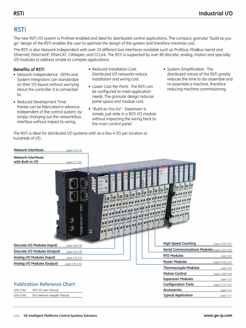
RSTiThe new RSTi I/O system is Profinet enabled and ideal for distributed control applications. The compact, granular “build as you go” design of the RSTi enables the user to optimize the design of the system and therefore minimize cost.
The RSTi is also Network Independent with over 10 different bus interfaces available such as Profibus, Modbus (serial and Ethernet), EthernetIP, EtherCAT, CANopen, and CCLink. The RSTi is supported by over 80 discrete, analog, motion and specialty I/O modules to address simple to complex applications.
Benefits of RSTi • NetworkIndependence:OEMsand
System Integrators can standardize on their I/O layout without worrying about the controller it is connected to.
• ReducedDevelopmentTime: Panels can be fabricated in advance, independent of the control system, by simply changing out the network/bus interface without impact to wiring.
• ReducedInstallationCost:Distributed I/O networks reduce installation and wiring cost.
• LowerCostPerPoint:TheRSTicanbe configured to meet application needs. The granular design reduces panel space and module cost.
• “BuildasYouGo”:Expansionissimple; just slide in a RSTi I/O module without impacting the wiring back to the main control panel.
• SystemSimplification:The distributed nature of the RSTi greatly reduces the time to dis-assemble and re-assemble a machine, therefore reducing machine commissioning.
Publication Reference ChartGFK-2745 RSTi I/O User Manual
GFK-2746 RSTi Network Adapter Manual
The RSTi is ideal for distributed I/O systems with as a few 4 I/O per location or hundreds of I/O.
Network Interfaces pages 3.75-3.76
Network Interfaces with Built-in I/O pages 3.77-3.87
Discrete I/O Modules (Input) pages 3.88-3.90
Discrete I/O Modules (Output) pages 3.94-3.98
Analog I/O Modules (Input) pages 3.91-3.93
Analog I/O Modules (Output) pages 3.99-3.101
High Speed Counting pages 3.106-3.107
Serial Communications Modules pages 3.104-3.105
RTD Modules page 3.102
Power Modules pages 3.110-3.112
Thermocouple Modules page 3.103
Motion Control pages 3.108-3.109
Expansion Modules page 3.113
Configuration Tools pages 3.114-3.115
Accessories page 3.116
Typical Application page 3.117
RSTiIndustrial I/O
3.75www.ge-ip.com GE Intelligent Platforms Control Systems Solutions
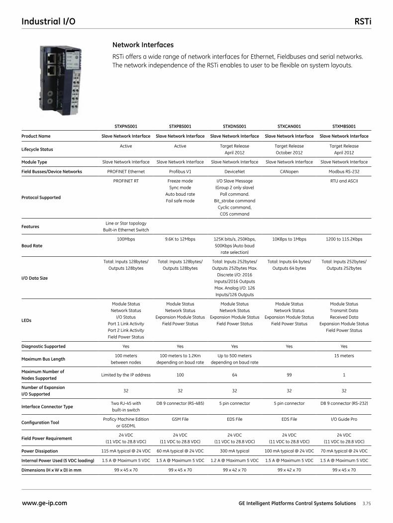
RSTi offers a wide range of network interfaces for Ethernet, Fieldbuses and serial networks. The network independence of the RSTi enables to user to be flexible on system layouts.
Network Interfaces
STXPNS001 STXPBS001 STXDNS001 STXCAN001 STXMBS001
Product Name Slave Network Interface Slave Network Interface Slave Network Interface Slave Network Interface Slave Network Interface
Lifecycle StatusActive Active Target Release
April 2012Target Release October 2012
Target Release April 2012
Module Type Slave Network Interface Slave Network Interface Slave Network Interface Slave Network Interface Slave Network Interface
Field Busses/Device Networks PROFINET Ethernet Profibus V1 DeviceNet CANopen Modbus RS-232
Protocol Supported
PROFINET RT Freeze mode Sync mode
Auto baud rate Fail safe mode
I/O Slave Message (Group 2 only slave)
Poll command. Bit_strobe command
Cyclic command, COS command
RTU and ASCII
FeaturesLine or Star topology
Built-in Ethernet Switch
Baud Rate100Mbps 9.6K to 12Mbps 125K bits/s, 250Kbps,
500Kbps (Auto baud rate selection)
10KBps to 1Mbps 1200 to 115.2Kbps
I/O Data Size
Total: Inputs 128bytes/Outputs 128bytes
Total: Inputs 128bytes/Outputs 128bytes
Total: Inputs 252bytes/Outputs 252bytes Max.
Discrete I/O: 2016 Inputs/2016 Outputs Max. Analog I/O: 126 Inputs/126 Outputs
Total: Inputs 64 bytes/ Outputs 64 bytes
Total: Inputs 252bytes/Outputs 252bytes
LEDs
Module Status Network Status
I/O Status Port 1 Link Activity Port 2 Link Activity Field Power Status
Module Status Network Status
Expansion Module Status Field Power Status
Module Status Network Status
Expansion Module Status Field Power Status
Module Status Network Status
Expansion Module Status Field Power Status
Module Status Transmit Data Received Data
Expansion Module Status Field Power Status
Diagnostic Supported Yes Yes Yes Yes Yes
Maximum Bus Length100 meters
between nodes100 meters to 1.2Km
depending on baud rateUp to 500 meters
depending on baud rate15 meters
Maximum Number of Nodes Supported
Limited by the IP address 100 64 99 1
Number of Expansion I/O Supported
32 32 32 32 32
Interface Connector TypeTwo RJ-45 with built-in switch
DB 9 connector (RS-485) 5 pin connector 5 pin connector DB 9 connector (RS-232)
Configuration ToolProficy Machine Edition
or GSDMLGSM File EDS File EDS File I/O Guide Pro
Field Power Requirement24 VDC
(11 VDC to 28.8 VDC) 24 VDC
(11 VDC to 28.8 VDC) 24 VDC
(11 VDC to 28.8 VDC)24 VDC
(11 VDC to 28.8 VDC) 24 VDC
(11 VDC to 28.8 VDC)
Power Dissipation 115 mA typical @ 24 VDC 60 mA typical @ 24 VDC 300 mA typical 100 mA typical @ 24 VDC 70 mA typical @ 24 VDC
Internal Power Used (5 VDC loading) 1.5 A @ Maximum 5 VDC 1.5 A @ Maximum 5 VDC 1.2 A @ Maximum 5 VDC 1.5 A @ Maximum 5 VDC 1.5 A @ Maximum 5 VDC
Dimensions (H x W x D) in mm 99 x 45 x 70 99 x 45 x 70 99 x 42 x 70 99 x 42 x 70 99 x 45 x 70
RSTi Industrial I/O
3.76 GE Intelligent Platforms Control Systems Solutions www.ge-ip.com
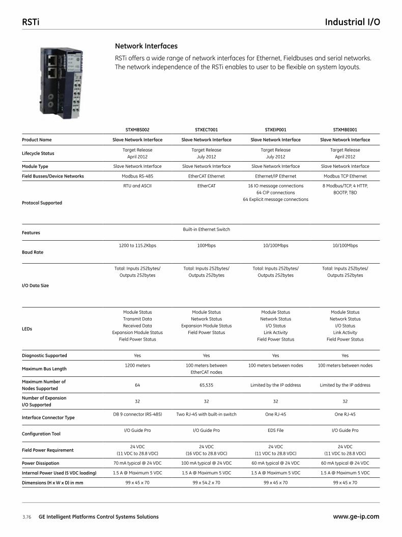
RSTi offers a wide range of network interfaces for Ethernet, Fieldbuses and serial networks. The network independence of the RSTi enables to user to be flexible on system layouts.
Network Interfaces
STXMBS002 STXECT001 STXEIP001 STXMBE001
Product Name Slave Network Interface Slave Network Interface Slave Network Interface Slave Network Interface
Lifecycle StatusTarget Release
April 2012Target Release
July 2012Target Release
July 2012Target Release
April 2012
Module Type Slave Network Interface Slave Network Interface Slave Network Interface Slave Network Interface
Field Busses/Device Networks Modbus RS-485 EtherCAT Ethernet Ethernet/IP Ethernet Modbus TCP Ethernet
Protocol Supported
RTU and ASCII EtherCAT 16 IO message connections 64 CIP connections
64 Explicit message connections
8 Modbus/TCP, 4 HTTP, BOOTP, TBD
FeaturesBuilt-in Ethernet Switch
Baud Rate1200 to 115.2Kbps 100Mbps 10/100Mbps 10/100Mbps
I/O Data Size
Total: Inputs 252bytes/ Outputs 252bytes
Total: Inputs 252bytes/ Outputs 252bytes
Total: Inputs 252bytes/ Outputs 252bytes
Total: Inputs 252bytes/ Outputs 252bytes
LEDs
Module Status Transmit Data Received Data
Expansion Module Status Field Power Status
Module Status Network Status
Expansion Module Status Field Power Status
Module Status Network Status
I/O Status Link Activity
Field Power Status
Module Status Network Status
I/O Status Link Activity
Field Power Status
Diagnostic Supported Yes Yes Yes Yes
Maximum Bus Length1200 meters 100 meters between
EtherCAT nodes100 meters between nodes 100 meters between nodes
Maximum Number of Nodes Supported
64 65,535 Limited by the IP address Limited by the IP address
Number of Expansion I/O Supported
32 32 32 32
Interface Connector TypeDB 9 connector (RS-485) Two RJ-45 with built-in switch One RJ-45 One RJ-45
Configuration ToolI/O Guide Pro I/O Guide Pro EDS File I/O Guide Pro
Field Power Requirement24 VDC
(11 VDC to 28.8 VDC) 24 VDC
(16 VDC to 28.8 VDC) 24 VDC
(11 VDC to 28.8 VDC) 24 VDC
(11 VDC to 28.8 VDC)
Power Dissipation 70 mA typical @ 24 VDC 100 mA typical @ 24 VDC 60 mA typical @ 24 VDC 60 mA typical @ 24 VDC
Internal Power Used (5 VDC loading) 1.5 A @ Maximum 5 VDC 1.5 A @ Maximum 5 VDC 1.5 A @ Maximum 5 VDC 1.5 A @ Maximum 5 VDC
Dimensions (H x W x D) in mm 99 x 45 x 70 99 x 54.2 x 70 99 x 45 x 70 99 x 45 x 70
RSTiIndustrial I/O
3.77www.ge-ip.com GE Intelligent Platforms Control Systems Solutions
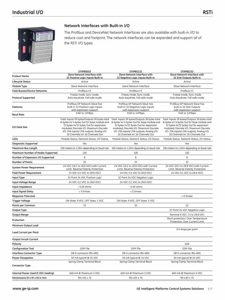
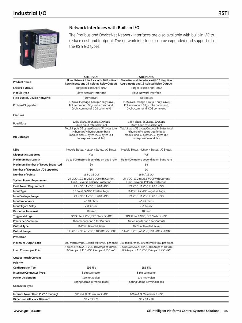
The Profibus and DeviceNet Network Interfaces are also available with built-in I/O to reduce cost and footprint. The network interfaces can be expanded and support all of the RSTi I/O types.
Network Interfaces with Built-in I/O
STXPBS032 STXPBS132 STXPBS232
Product Name Slave Network Interface with 32 Positive Logic Inputs Built-in
Slave Network Interface with 32 Negative Logic Inputs Built-in
Slave Network Interface with 32 Sink Outputs Built-in
Lifecycle Status Active Active Active
Module Type Slave Network Interface Slave Network Interface Slave Network Interface
Field Busses/Device Networks Profibus V1 Profibus V1 Profibus V1
Protocol SupportedFreeze mode, Sync mode,
Auto baudrate, Fail safe modeFreeze mode, Sync mode,
Auto baudrate, Fail safe modeFreeze mode, Sync mode
Auto baudrate, Fail safe mode
FeaturesProfibus DP Network Slave has built-in 32 Positive Logic Inputs
with expansion support
Profibus DP Network Slave has built-in 32 Negative Logic Inputs
with expansion support
Profibus DP Network Slave has built-in 32 Sink Outputs with expansion support
Baud Rate 9.6K to 12Mbps 9.6K to 12Mbps 9.6K to 12Mbps
I/O Data Size
Total: Inputs 36 bytes/Outputs 36 bytes total (4 bytes In/ 4 bytes Out for base module and
32 bytes In/32 bytes Out for expansion modules); Discrete I/O: Maximum Discrete I/O: 256 inputs/ 256 outputs; Analog I/O:
16 Channels In/ 16 Channels Out
Total: Inputs 36 bytes/Outputs 36 bytes total (4 bytes In/ 4 bytes Out for base module and
32 bytes In/32 bytes Out for expansion modules); Discrete I/O: Maximum Discrete I/O: 256 inputs/ 256 outputs; Analog I/O:
16 Channels In/ 16 Channels Out
Total: Inputs 36 bytes/Outputs 36 bytes total (4 bytes In/ 4 bytes Out for base module and
32 bytes In/32 bytes Out for expansion modules); Discrete I/O: Maximum Discrete I/O: 256 inputs/ 256 outputs; Analog I/O:
16 Channels In/ 16 Channels Out
LEDs Module Status, Network Status, I/O Status Module Status, Network Status, I/O Status Module Status, Network Status, I/O Status
Diagnostic Supported Yes Yes Yes
Maximum Bus Length 100 meters to 1.2Km depending on baud rate 100 meters to 1.2Km depending on baud rate 100 meters to 1.2Km depending on baud rate
Maximum Number of Nodes Supported 100 100 100
Number of Expansion I/O Supported 8 8 8
Number of Points 32 32 32
System Power Requirement 24 VDC (19.2 to 28.8 VDC) with Current Limit, Reverse Polarity Protection
24 VDC (19.2 to 28.8 VDC) with Current Limit, Reverse Polarity Protection
24 VDC (19.2 to 28.8 VDC) with Current Limit, Reverse Polarity Protection
Field Power Requirement 24 VDC (11 VDC to 28.8 VDC) 24 VDC (11 VDC to 28.8 VDC) 24 VDC (11 VDC to 28.8 VDC)
Input Type 32 Point 24 VDC Positive Logic 32 Point 24 VDC Negative Logic
Input Voltage Range 24 VDC (11 VDC to 28.8 VDC) 24 VDC (11 VDC to 28.8 VDC)
Input Impedance ~5.4K ohms ~5.4K ohms
Input Signal Delay < 0.5msec < 0.5msec
Response Time (ms) < 0.3msec
Trigger Voltage ON State: 9 VDC, OFF State: 5 VDC ON State: 9 VDC, OFF State: 5 VDC
Points per Common 32 32 32
Output Type 32 Point 24 VDC Negative Logic
Output Range Nominal 0 VDC; 11 to 28.8 VDC
Protection Short protection, Over Temperature Protection, Over Current Limit
Minimum Output Load
Load Current per Point0.5 Amps per point
Output Inrush Current
Polarity Sink
Configuration Tool GSM File GSM File GSM File
Interface Connector Type DB 9 connector (RS-485) DB 9 connector (RS-485) DB 9 connector (RS-485)
Power Dissipation 50 mA typical @ 24 VDC 50 mA typical @ 24 VDC 50 mA typical @ 24 VDC
Connector TypeSpring Clamp Terminal Block Spring Clamp Terminal Block Spring Clamp Terminal Block
Internal Power Used (5 VDC loading) 400 mA @ Maximum 5 VDC 400 mA @ Maximum 5 VDC 400 mA @ Maximum 5 VDC
Dimensions (H x W x D) in mm 99 x 83 x 70 99 x 83 x 70 99 x 83 x 70
RSTi Industrial I/O
3.78 GE Intelligent Platforms Control Systems Solutions www.ge-ip.com
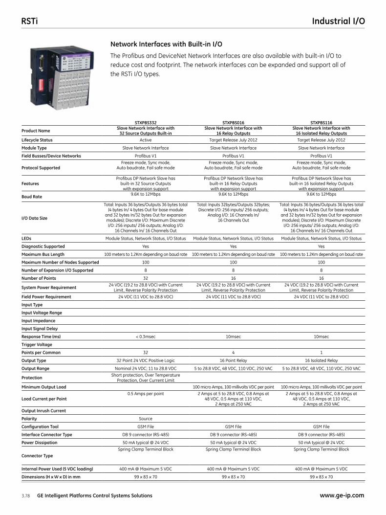
The Profibus and DeviceNet Network Interfaces are also available with built-in I/O to reduce cost and footprint. The network interfaces can be expanded and support all of the RSTi I/O types.
Network Interfaces with Built-in I/O
STXPBS332 STXPBS016 STXPBS116
Product Name Slave Network Interface with 32 Source Outputs Built-in
Slave Network Interface with 16 Relay Outputs
Slave Network Interface with 16 Isolated Relay Outputs
Lifecycle Status Active Target Release July 2012 Target Release July 2012
Module Type Slave Network Interface Slave Network Interface Slave Network Interface
Field Busses/Device Networks Profibus V1 Profibus V1 Profibus V1
Protocol SupportedFreeze mode, Sync mode,
Auto baudrate, Fail safe modeFreeze mode, Sync mode,
Auto baudrate, Fail safe modeFreeze mode, Sync mode,
Auto baudrate, Fail safe mode
FeaturesProfibus DP Network Slave has
built-in 32 Source Outputs with expansion support
Profibus DP Network Slave has built-in 16 Relay Outputs with expansion support
Profibus DP Network Slave has built-in 16 Isolated Relay Outputs
with expansion support
Baud Rate 9.6K to 12Mbps 9.6K to 12Mbps 9.6K to 12Mbps
I/O Data Size
Total: Inputs 36 bytes/Outputs 36 bytes total (4 bytes In/ 4 bytes Out for base module
and 32 bytes In/32 bytes Out for expansion modules); Discrete I/O: Maximum Discrete I/O: 256 inputs/ 256 outputs; Analog I/O:
16 Channels In/ 16 Channels Out
Total: Inputs 32bytes/Outputs 32bytes; Discrete I/O: 256 inputs/ 256 outputs;
Analog I/O: 16 Channels In/ 16 Channels Out
Total: Inputs 36 bytes/Outputs 36 bytes total (4 bytes In/ 4 bytes Out for base module
and 32 bytes In/32 bytes Out for expansion modules); Discrete I/O: Maximum Discrete I/O: 256 inputs/ 256 outputs; Analog I/O:
16 Channels In/ 16 Channels Out
LEDs Module Status, Network Status, I/O Status Module Status, Network Status, I/O Status Module Status, Network Status, I/O Status
Diagnostic Supported Yes Yes Yes
Maximum Bus Length 100 meters to 1.2Km depending on baud rate 100 meters to 1.2Km depending on baud rate 100 meters to 1.2Km depending on baud rate
Maximum Number of Nodes Supported 100 100 100
Number of Expansion I/O Supported 8 8 8
Number of Points 32 16 16
System Power Requirement 24 VDC (19.2 to 28.8 VDC) with Current Limit, Reverse Polarity Protection
24 VDC (19.2 to 28.8 VDC) with Current Limit, Reverse Polarity Protection
24 VDC (19.2 to 28.8 VDC) with Current Limit, Reverse Polarity Protection
Field Power Requirement 24 VDC (11 VDC to 28.8 VDC) 24 VDC (11 VDC to 28.8 VDC) 24 VDC (11 VDC to 28.8 VDC)
Input Type
Input Voltage Range
Input Impedance
Input Signal Delay
Response Time (ms) < 0.3msec 10msec 10msec
Trigger Voltage
Points per Common 32 4 1
Output Type 32 Point 24 VDC Positive Logic 16 Point Relay 16 Isolated Relay
Output Range Nominal 24 VDC; 11 to 28.8 VDC 5 to 28.8 VDC, 48 VDC, 110 VDC, 250 VAC 5 to 28.8 VDC, 48 VDC, 110 VDC, 250 VAC
Protection Short protection, Over Temperature Protection, Over Current Limit
Minimum Output Load 100 micro Amps, 100 millivolts VDC per point 100 micro Amps, 100 millivolts VDC per point
Load Current per Point0.5 Amps per point 2 Amps at 5 to 28.8 VDC, 0.8 Amps at
48 VDC, 0.5 Amps at 110 VDC, 2 Amps at 250 VAC
2 Amps at 5 to 28.8 VDC, 0.8 Amps at 48 VDC, 0.5 Amps at 110 VDC,
2 Amps at 250 VAC
Output Inrush Current
Polarity Source
Configuration Tool GSM File GSM File GSM File
Interface Connector Type DB 9 connector (RS-485) DB 9 connector (RS-485) DB 9 connector (RS-485)
Power Dissipation 50 mA typical @ 24 VDC 50 mA typical @ 24 VDC 50 mA typical @ 24 VDC
Connector TypeSpring Clamp Terminal Block Spring Clamp Terminal Block Spring Clamp Terminal Block
Internal Power Used (5 VDC loading) 400 mA @ Maximum 5 VDC 400 mA @ Maximum 5 VDC 400 mA @ Maximum 5 VDC
Dimensions (H x W x D) in mm 99 x 83 x 70 99 x 83 x 70 99 x 83 x 70
RSTiIndustrial I/O
3.79www.ge-ip.com GE Intelligent Platforms Control Systems Solutions
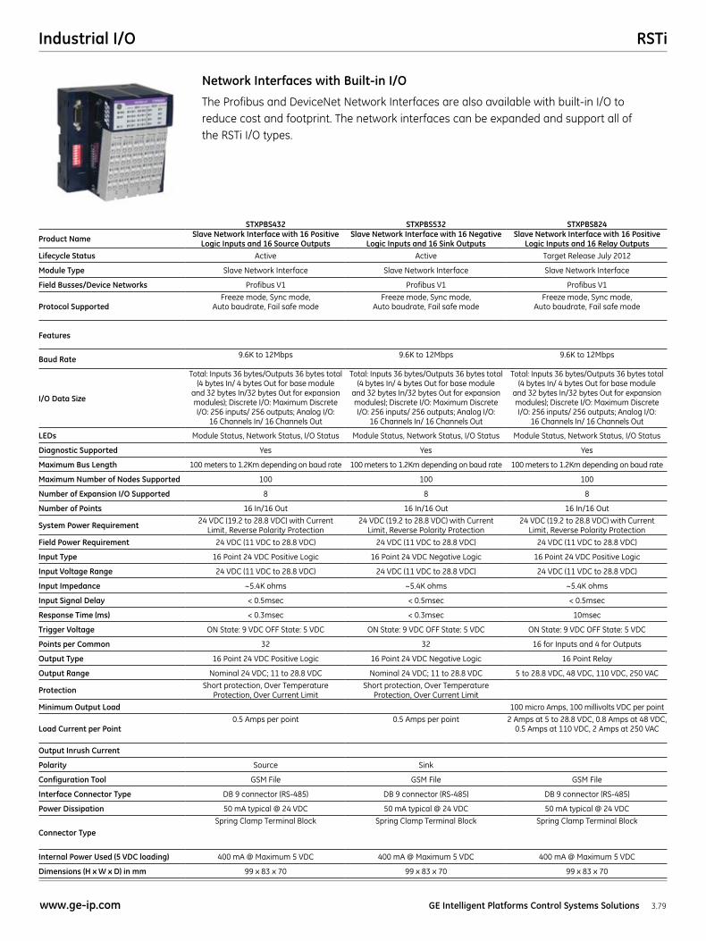
The Profibus and DeviceNet Network Interfaces are also available with built-in I/O to reduce cost and footprint. The network interfaces can be expanded and support all of the RSTi I/O types.
Network Interfaces with Built-in I/O
STXPBS432 STXPBS532 STXPBS824
Product Name Slave Network Interface with 16 Positive Logic Inputs and 16 Source Outputs
Slave Network Interface with 16 Negative Logic Inputs and 16 Sink Outputs
Slave Network Interface with 16 Positive Logic Inputs and 16 Relay Outputs
Lifecycle Status Active Active Target Release July 2012
Module Type Slave Network Interface Slave Network Interface Slave Network Interface
Field Busses/Device Networks Profibus V1 Profibus V1 Profibus V1
Protocol SupportedFreeze mode, Sync mode,
Auto baudrate, Fail safe modeFreeze mode, Sync mode,
Auto baudrate, Fail safe modeFreeze mode, Sync mode,
Auto baudrate, Fail safe mode
Features
Baud Rate 9.6K to 12Mbps 9.6K to 12Mbps 9.6K to 12Mbps
I/O Data Size
Total: Inputs 36 bytes/Outputs 36 bytes total (4 bytes In/ 4 bytes Out for base module
and 32 bytes In/32 bytes Out for expansion modules); Discrete I/O: Maximum Discrete I/O: 256 inputs/ 256 outputs; Analog I/O:
16 Channels In/ 16 Channels Out
Total: Inputs 36 bytes/Outputs 36 bytes total (4 bytes In/ 4 bytes Out for base module
and 32 bytes In/32 bytes Out for expansion modules); Discrete I/O: Maximum Discrete I/O: 256 inputs/ 256 outputs; Analog I/O:
16 Channels In/ 16 Channels Out
Total: Inputs 36 bytes/Outputs 36 bytes total (4 bytes In/ 4 bytes Out for base module
and 32 bytes In/32 bytes Out for expansion modules); Discrete I/O: Maximum Discrete I/O: 256 inputs/ 256 outputs; Analog I/O:
16 Channels In/ 16 Channels Out
LEDs Module Status, Network Status, I/O Status Module Status, Network Status, I/O Status Module Status, Network Status, I/O Status
Diagnostic Supported Yes Yes Yes
Maximum Bus Length 100 meters to 1.2Km depending on baud rate 100 meters to 1.2Km depending on baud rate 100 meters to 1.2Km depending on baud rate
Maximum Number of Nodes Supported 100 100 100
Number of Expansion I/O Supported 8 8 8
Number of Points 16 In/16 Out 16 In/16 Out 16 In/16 Out
System Power Requirement 24 VDC (19.2 to 28.8 VDC) with Current Limit, Reverse Polarity Protection
24 VDC (19.2 to 28.8 VDC) with Current Limit, Reverse Polarity Protection
24 VDC (19.2 to 28.8 VDC) with Current Limit, Reverse Polarity Protection
Field Power Requirement 24 VDC (11 VDC to 28.8 VDC) 24 VDC (11 VDC to 28.8 VDC) 24 VDC (11 VDC to 28.8 VDC)
Input Type 16 Point 24 VDC Positive Logic 16 Point 24 VDC Negative Logic 16 Point 24 VDC Positive Logic
Input Voltage Range 24 VDC (11 VDC to 28.8 VDC) 24 VDC (11 VDC to 28.8 VDC) 24 VDC (11 VDC to 28.8 VDC)
Input Impedance ~5.4K ohms ~5.4K ohms ~5.4K ohms
Input Signal Delay < 0.5msec < 0.5msec < 0.5msec
Response Time (ms) < 0.3msec < 0.3msec 10msec
Trigger Voltage ON State: 9 VDC OFF State: 5 VDC ON State: 9 VDC OFF State: 5 VDC ON State: 9 VDC OFF State: 5 VDC
Points per Common 32 32 16 for Inputs and 4 for Outputs
Output Type 16 Point 24 VDC Positive Logic 16 Point 24 VDC Negative Logic 16 Point Relay
Output Range Nominal 24 VDC; 11 to 28.8 VDC Nominal 24 VDC; 11 to 28.8 VDC 5 to 28.8 VDC, 48 VDC, 110 VDC, 250 VAC
Protection Short protection, Over Temperature Protection, Over Current Limit
Short protection, Over Temperature Protection, Over Current Limit
Minimum Output Load 100 micro Amps, 100 millivolts VDC per point
Load Current per Point0.5 Amps per point 0.5 Amps per point 2 Amps at 5 to 28.8 VDC, 0.8 Amps at 48 VDC,
0.5 Amps at 110 VDC, 2 Amps at 250 VAC
Output Inrush Current
Polarity Source Sink
Configuration Tool GSM File GSM File GSM File
Interface Connector Type DB 9 connector (RS-485) DB 9 connector (RS-485) DB 9 connector (RS-485)
Power Dissipation 50 mA typical @ 24 VDC 50 mA typical @ 24 VDC 50 mA typical @ 24 VDC
Connector TypeSpring Clamp Terminal Block Spring Clamp Terminal Block Spring Clamp Terminal Block
Internal Power Used (5 VDC loading) 400 mA @ Maximum 5 VDC 400 mA @ Maximum 5 VDC 400 mA @ Maximum 5 VDC
Dimensions (H x W x D) in mm 99 x 83 x 70 99 x 83 x 70 99 x 83 x 70
RSTi Industrial I/O
3.80 GE Intelligent Platforms Control Systems Solutions www.ge-ip.com
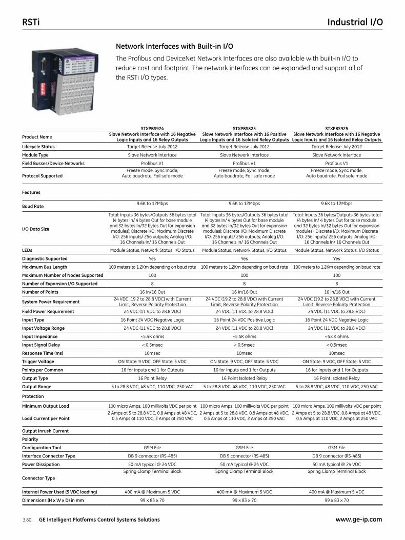
The Profibus and DeviceNet Network Interfaces are also available with built-in I/O to reduce cost and footprint. The network interfaces can be expanded and support all of the RSTi I/O types.
Network Interfaces with Built-in I/O
STXPBS924 STXPBS825 STXPBS925
Product Name Slave Network Interface with 16 Negative Logic Inputs and 16 Relay Outputs
Slave Network Interface with 16 Positive Logic Inputs and 16 Isolated Relay Outputs
Slave Network Interface with 16 Negative Logic Inputs and 16 Isolated Relay Outputs
Lifecycle Status Target Release July 2012 Target Release July 2012 Target Release July 2012
Module Type Slave Network Interface Slave Network Interface Slave Network Interface
Field Busses/Device Networks Profibus V1 Profibus V1 Profibus V1
Protocol SupportedFreeze mode, Sync mode,
Auto baudrate, Fail safe modeFreeze mode, Sync mode,
Auto baudrate, Fail safe modeFreeze mode, Sync mode,
Auto baudrate, Fail safe mode
Features
Baud Rate9.6K to 12Mbps 9.6K to 12Mbps 9.6K to 12Mbps
I/O Data Size
Total: Inputs 36 bytes/Outputs 36 bytes total (4 bytes In/ 4 bytes Out for base module
and 32 bytes In/32 bytes Out for expansion modules); Discrete I/O: Maximum Discrete I/O: 256 inputs/ 256 outputs; Analog I/O:
16 Channels In/ 16 Channels Out
Total: Inputs 36 bytes/Outputs 36 bytes total (4 bytes In/ 4 bytes Out for base module
and 32 bytes In/32 bytes Out for expansion modules); Discrete I/O: Maximum Discrete I/O: 256 inputs/ 256 outputs; Analog I/O:
16 Channels In/ 16 Channels Out
Total: Inputs 36 bytes/Outputs 36 bytes total (4 bytes In/ 4 bytes Out for base module
and 32 bytes In/32 bytes Out for expansion modules); Discrete I/O: Maximum Discrete I/O: 256 inputs/ 256 outputs; Analog I/O:
16 Channels In/ 16 Channels Out
LEDs Module Status, Network Status, I/O Status Module Status, Network Status, I/O Status Module Status, Network Status, I/O Status
Diagnostic Supported Yes Yes Yes
Maximum Bus Length 100 meters to 1.2Km depending on baud rate 100 meters to 1.2Km depending on baud rate 100 meters to 1.2Km depending on baud rate
Maximum Number of Nodes Supported 100 100 100
Number of Expansion I/O Supported 8 8 8
Number of Points 16 In/16 Out 16 In/16 Out 16 In/16 Out
System Power Requirement 24 VDC (19.2 to 28.8 VDC) with Current Limit, Reverse Polarity Protection
24 VDC (19.2 to 28.8 VDC) with Current Limit, Reverse Polarity Protection
24 VDC (19.2 to 28.8 VDC) with Current Limit, Reverse Polarity Protection
Field Power Requirement 24 VDC (11 VDC to 28.8 VDC) 24 VDC (11 VDC to 28.8 VDC) 24 VDC (11 VDC to 28.8 VDC)
Input Type 16 Point 24 VDC Negative Logic 16 Point 24 VDC Positive Logic 16 Point 24 VDC Negative Logic
Input Voltage Range 24 VDC (11 VDC to 28.8 VDC) 24 VDC (11 VDC to 28.8 VDC) 24 VDC (11 VDC to 28.8 VDC)
Input Impedance ~5.4K ohms ~5.4K ohms ~5.4K ohms
Input Signal Delay < 0.5msec < 0.5msec < 0.5msec
Response Time (ms) 10msec 10msec 10msec
Trigger Voltage ON State: 9 VDC, OFF State: 5 VDC ON State: 9 VDC, OFF State: 5 VDC ON State: 9 VDC, OFF State: 5 VDC
Points per Common 16 for Inputs and 1 for Outputs 16 for Inputs and 1 for Outputs 16 for Inputs and 1 for Outputs
Output Type 16 Point Relay 16 Point Isolated Relay 16 Point Isolated Relay
Output Range 5 to 28.8 VDC, 48 VDC, 110 VDC, 250 VAC 5 to 28.8 VDC, 48 VDC, 110 VDC, 250 VAC 5 to 28.8 VDC, 48 VDC, 110 VDC, 250 VAC
Protection
Minimum Output Load 100 micro Amps, 100 millivolts VDC per point 100 micro Amps, 100 millivolts VDC per point 100 micro Amps, 100 millivolts VDC per point
Load Current per Point2 Amps at 5 to 28.8 VDC, 0.8 Amps at 48 VDC,
0.5 Amps at 110 VDC, 2 Amps at 250 VAC2 Amps at 5 to 28.8 VDC, 0.8 Amps at 48 VDC,
0.5 Amps at 110 VDC, 2 Amps at 250 VAC2 Amps at 5 to 28.8 VDC, 0.8 Amps at 48 VDC,
0.5 Amps at 110 VDC, 2 Amps at 250 VAC
Output Inrush Current
Polarity
Configuration Tool GSM File GSM File GSM File
Interface Connector Type DB 9 connector (RS-485) DB 9 connector (RS-485) DB 9 connector (RS-485)
Power Dissipation 50 mA typical @ 24 VDC 50 mA typical @ 24 VDC 50 mA typical @ 24 VDC
Connector TypeSpring Clamp Terminal Block Spring Clamp Terminal Block Spring Clamp Terminal Block
Internal Power Used (5 VDC loading) 400 mA @ Maximum 5 VDC 400 mA @ Maximum 5 VDC 400 mA @ Maximum 5 VDC
Dimensions (H x W x D) in mm 99 x 83 x 70 99 x 83 x 70 99 x 83 x 70
RSTiIndustrial I/O
3.81www.ge-ip.com GE Intelligent Platforms Control Systems Solutions
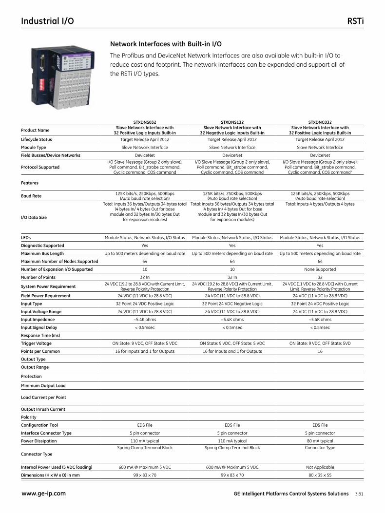
STXDNS032 STXDNS132 STXDNC032
Product Name Slave Network Interface with 32 Positive Logic Inputs Built-in
Slave Network Interface with 32 Negative Logic Inputs Built-in
Slave Network Interface with 32 Positive Logic Inputs Built-in
Lifecycle Status Target Release April 2012 Target Release April 2012 Target Release April 2012
Module Type Slave Network Interface Slave Network Interface Slave Network Interface
Field Busses/Device Networks DeviceNet DeviceNet DeviceNet
Protocol SupportedI/O Slave Message (Group 2 only slave), Poll command. Bit_strobe command,
Cyclic command, COS command
I/O Slave Message (Group 2 only slave), Poll command. Bit_strobe command,
Cyclic command, COS command
I/O Slave Message (Group 2 only slave), Poll command. Bit_strobe command,
Cyclic command, COS command”
Features
Baud Rate 125K bits/s, 250Kbps, 500Kbps (Auto baud rate selection)
125K bits/s, 250Kbps, 500Kbps (Auto baud rate selection)
125K bits/s, 250Kbps, 500Kbps (Auto baud rate selection)
I/O Data Size
Total: Inputs 36 bytes/Outputs 34 bytes total (4 bytes In/ 4 bytes Out for base
module and 32 bytes In/30 bytes Out for expansion modules)
Total: Inputs 36 bytes/Outputs 34 bytes total (4 bytes In/ 4 bytes Out for base
module and 32 bytes In/30 bytes Out for expansion modules)
Total: Inputs 4 bytes/Outputs 4 bytes
LEDs Module Status, Network Status, I/O Status Module Status, Network Status, I/O Status Module Status, Network Status, I/O Status
Diagnostic Supported Yes Yes Yes
Maximum Bus Length Up to 500 meters depending on baud rate Up to 500 meters depending on baud rate Up to 500 meters depending on baud rate
Maximum Number of Nodes Supported 64 64 64
Number of Expansion I/O Supported 10 10 None Supported
Number of Points 32 In 32 In 32
System Power Requirement 24 VDC (19.2 to 28.8 VDC) with Current Limit, Reverse Polarity Protection
24 VDC (19.2 to 28.8 VDC) with Current Limit, Reverse Polarity Protection
24 VDC (11 VDC to 28.8 VDC) with Current Limit, Reverse Polarity Protection
Field Power Requirement 24 VDC (11 VDC to 28.8 VDC) 24 VDC (11 VDC to 28.8 VDC) 24 VDC (11 VDC to 28.8 VDC)
Input Type 32 Point 24 VDC Positive Logic 32 Point 24 VDC Negative Logic 32 Point 24 VDC Positive Logic
Input Voltage Range 24 VDC (11 VDC to 28.8 VDC) 24 VDC (11 VDC to 28.8 VDC) 24 VDC (11 VDC to 28.8 VDC)
Input Impedance ~5.4K ohms ~5.4K ohms ~5.4K ohms
Input Signal Delay < 0.5msec < 0.5msec < 0.5msec
Response Time (ms)
Trigger Voltage ON State: 9 VDC, OFF State: 5 VDC ON State: 9 VDC, OFF State: 5 VDC ON State: 9 VDC, OFF State: 5VD
Points per Common 16 for Inputs and 1 for Outputs 16 for Inputs and 1 for Outputs 16
Output Type
Output Range
Protection
Minimum Output Load
Load Current per Point
Output Inrush Current
Polarity
Configuration Tool EDS File EDS File EDS File
Interface Connector Type 5 pin connector 5 pin connector 5 pin connector
Power Dissipation 110 mA typical 110 mA typical 80 mA typical
Connector TypeSpring Clamp Terminal Block Spring Clamp Terminal Block Connector Type
Internal Power Used (5 VDC loading) 600 mA @ Maximum 5 VDC 600 mA @ Maximum 5 VDC Not Applicable
Dimensions (H x W x D) in mm 99 x 83 x 70 99 x 83 x 70 80 x 35 x 55
The Profibus and DeviceNet Network Interfaces are also available with built-in I/O to reduce cost and footprint. The network interfaces can be expanded and support all of the RSTi I/O types.
Network Interfaces with Built-in I/O
RSTi Industrial I/O
3.82 GE Intelligent Platforms Control Systems Solutions www.ge-ip.com
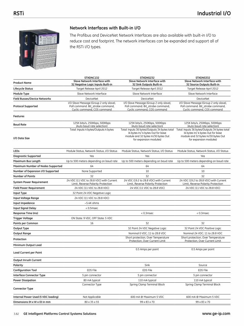
STXDNC132 STXDNS232 STXDNS332
Product Name Slave Network Interface with 32 Negative Logic Inputs Built-in
Slave Network Interface with 32 Sink Outputs Built-in
Slave Network Interface with 32 Source Outputs Built-in
Lifecycle Status Target Release April 2012 Target Release April 2012 Target Release April 2012
Module Type Slave Network Interface Slave Network Interface Slave Network Interface
Field Busses/Device Networks DeviceNet DeviceNet DeviceNet
Protocol SupportedI/O Slave Message (Group 2 only slave), Poll command. Bit_strobe command,
Cyclic command, COS command
I/O Slave Message (Group 2 only slave), Poll command. Bit_strobe command,
Cyclic command, COS command
I/O Slave Message (Group 2 only slave), Poll command. Bit_strobe command,
Cyclic command, COS command
Features
Baud Rate 125K bits/s, 250Kbps, 500Kbps (Auto baud rate selection)
125K bits/s, 250Kbps, 500Kbps (Auto baud rate selection)
125K bits/s, 250Kbps, 500Kbps (Auto baud rate selection)
I/O Data Size
Total: Inputs 4 bytes/Outputs 4 bytes Total: Inputs 36 bytes/Outputs 34 bytes total (4 bytes In/ 4 bytes Out for base
module and 32 bytes In/30 bytes Out for expansion modules)
Total: Inputs 36 bytes/Outputs 34 bytes total (4 bytes In/ 4 bytes Out for base
module and 32 bytes In/30 bytes Out for expansion modules)
LEDs Module Status, Network Status, I/O Status Module Status, Network Status, I/O Status Module Status, Network Status, I/O Status
Diagnostic Supported Yes Yes Yes
Maximum Bus Length Up to 500 meters depending on baud rate Up to 500 meters depending on baud rate Up to 500 meters depending on baud rate
Maximum Number of Nodes Supported 64 64 64
Number of Expansion I/O Supported None Supported 10 10
Number of Points 32 32 32
System Power Requirement 24 VDC (11 VDC to 28.8 VDC) with Current Limit, Reverse Polarity Protection
24 VDC (19.2 to 28.8 VDC) with Current Limit, Reverse Polarity Protection
24 VDC (19.2 to 28.8 VDC) with Current Limit, Reverse Polarity Protection
Field Power Requirement 24 VDC (11 VDC to 28.8 VDC) 24 VDC (11 VDC to 28.8 VDC) 24 VDC (11 VDC to 28.8 VDC)
Input Type 32 Point 24 VDC Negative Logic
Input Voltage Range 24 VDC (11 VDC to 28.8 VDC)
Input Impedance ~5.4K ohms
Input Signal Delay < 0.5msec
Response Time (ms) < 0.3msec < 0.3msec
Trigger Voltage ON State: 9 VDC, OFF State: 5 VDC
Points per Common 16 32 32
Output Type 32 Point 24 VDC Negative Logic 32 Point 24 VDC Positive Logic
Output Range Nominal 0 VDC; 11 to 28.8 VDC Nominal 24 VDC; 11 to 28.8 VDC
Protection Short protection, Over Temperature Protection, Over Current Limit
Short protection, Over Temperature Protection, Over Current Limit
Minimum Output Load
Load Current per Point0.5 Amps per point 0.5 Amps per point
Output Inrush Current
Polarity Sink Source
Configuration Tool EDS File EDS File EDS File
Interface Connector Type 5 pin connector 5 pin connector 5 pin connector
Power Dissipation 80 mA typical 110 mA typical 110 mA typical
Connector TypeConnector Type Spring Clamp Terminal Block Spring Clamp Terminal Block
Internal Power Used (5 VDC loading) Not Applicable 600 mA @ Maximum 5 VDC 600 mA @ Maximum 5 VDC
Dimensions (H x W x D) in mm 80 x 35 x 55 99 x 83 x 70 99 x 83 x 70
The Profibus and DeviceNet Network Interfaces are also available with built-in I/O to reduce cost and footprint. The network interfaces can be expanded and support all of the RSTi I/O types.
Network Interfaces with Built-in I/O
RSTiIndustrial I/O
3.83www.ge-ip.com GE Intelligent Platforms Control Systems Solutions
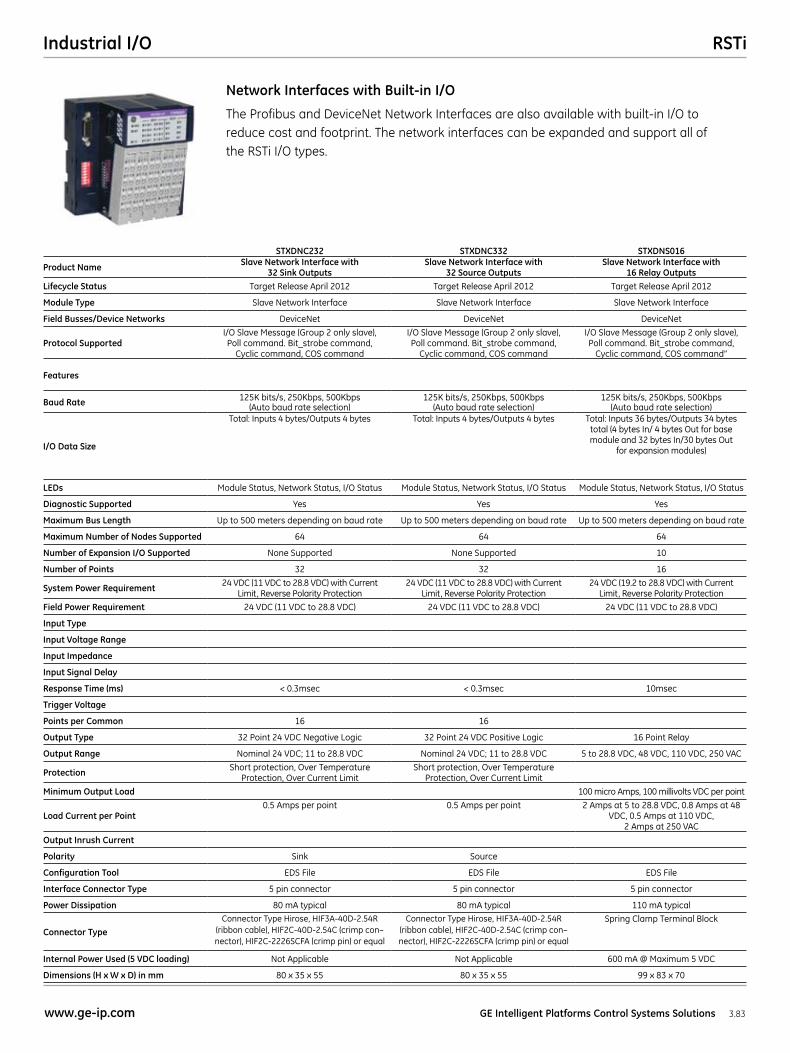
STXDNC232 STXDNC332 STXDNS016
Product Name Slave Network Interface with 32 Sink Outputs
Slave Network Interface with 32 Source Outputs
Slave Network Interface with 16 Relay Outputs
Lifecycle Status Target Release April 2012 Target Release April 2012 Target Release April 2012
Module Type Slave Network Interface Slave Network Interface Slave Network Interface
Field Busses/Device Networks DeviceNet DeviceNet DeviceNet
Protocol SupportedI/O Slave Message (Group 2 only slave), Poll command. Bit_strobe command,
Cyclic command, COS command
I/O Slave Message (Group 2 only slave), Poll command. Bit_strobe command,
Cyclic command, COS command
I/O Slave Message (Group 2 only slave), Poll command. Bit_strobe command,
Cyclic command, COS command”
Features
Baud Rate 125K bits/s, 250Kbps, 500Kbps (Auto baud rate selection)
125K bits/s, 250Kbps, 500Kbps (Auto baud rate selection)
125K bits/s, 250Kbps, 500Kbps (Auto baud rate selection)
I/O Data Size
Total: Inputs 4 bytes/Outputs 4 bytes Total: Inputs 4 bytes/Outputs 4 bytes Total: Inputs 36 bytes/Outputs 34 bytes total (4 bytes In/ 4 bytes Out for base module and 32 bytes In/30 bytes Out
for expansion modules)
LEDs Module Status, Network Status, I/O Status Module Status, Network Status, I/O Status Module Status, Network Status, I/O Status
Diagnostic Supported Yes Yes Yes
Maximum Bus Length Up to 500 meters depending on baud rate Up to 500 meters depending on baud rate Up to 500 meters depending on baud rate
Maximum Number of Nodes Supported 64 64 64
Number of Expansion I/O Supported None Supported None Supported 10
Number of Points 32 32 16
System Power Requirement 24 VDC (11 VDC to 28.8 VDC) with Current Limit, Reverse Polarity Protection
24 VDC (11 VDC to 28.8 VDC) with Current Limit, Reverse Polarity Protection
24 VDC (19.2 to 28.8 VDC) with Current Limit, Reverse Polarity Protection
Field Power Requirement 24 VDC (11 VDC to 28.8 VDC) 24 VDC (11 VDC to 28.8 VDC) 24 VDC (11 VDC to 28.8 VDC)
Input Type
Input Voltage Range
Input Impedance
Input Signal Delay
Response Time (ms) < 0.3msec < 0.3msec 10msec
Trigger Voltage
Points per Common 16 16
Output Type 32 Point 24 VDC Negative Logic 32 Point 24 VDC Positive Logic 16 Point Relay
Output Range Nominal 24 VDC; 11 to 28.8 VDC Nominal 24 VDC; 11 to 28.8 VDC 5 to 28.8 VDC, 48 VDC, 110 VDC, 250 VAC
Protection Short protection, Over Temperature Protection, Over Current Limit
Short protection, Over Temperature Protection, Over Current Limit
Minimum Output Load 100 micro Amps, 100 millivolts VDC per point
Load Current per Point0.5 Amps per point 0.5 Amps per point 2 Amps at 5 to 28.8 VDC, 0.8 Amps at 48
VDC, 0.5 Amps at 110 VDC, 2 Amps at 250 VAC
Output Inrush Current
Polarity Sink Source
Configuration Tool EDS File EDS File EDS File
Interface Connector Type 5 pin connector 5 pin connector 5 pin connector
Power Dissipation 80 mA typical 80 mA typical 110 mA typical
Connector Type
Connector Type Hirose, HIF3A-40D-2.54R (ribbon cable), HIF2C-40D-2.54C (crimp con–nector), HIF2C-2226SCFA (crimp pin) or equal
Connector Type Hirose, HIF3A-40D-2.54R (ribbon cable), HIF2C-40D-2.54C (crimp con–nector), HIF2C-2226SCFA (crimp pin) or equal
Spring Clamp Terminal Block
Internal Power Used (5 VDC loading) Not Applicable Not Applicable 600 mA @ Maximum 5 VDC
Dimensions (H x W x D) in mm 80 x 35 x 55 80 x 35 x 55 99 x 83 x 70
The Profibus and DeviceNet Network Interfaces are also available with built-in I/O to reduce cost and footprint. The network interfaces can be expanded and support all of the RSTi I/O types.
Network Interfaces with Built-in I/O
RSTi Industrial I/O
3.84 GE Intelligent Platforms Control Systems Solutions www.ge-ip.com
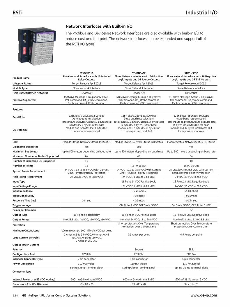
STXDNS116 STXDNS432 STXDNS532
Product Name Slave Network Interface with 16 Isolated Relay Outputs
Slave Network Interface with 16 Positive Logic Inputs and 16 Source Outputs
Slave Network Interface with 16 Negative Logic Inputs and 16 Sink Outputs
Lifecycle Status Target Release April 2012 Target Release April 2012 Target Release April 2012
Module Type Slave Network Interface Slave Network Interface Slave Network Interface
Field Busses/Device Networks DeviceNet DeviceNet DeviceNet
Protocol SupportedI/O Slave Message (Group 2 only slave), Poll command. Bit_strobe command,
Cyclic command, COS command
I/O Slave Message (Group 2 only slave), Poll command. Bit_strobe command,
Cyclic command, COS command
I/O Slave Message (Group 2 only slave), Poll command. Bit_strobe command,
Cyclic command, COS command”
Features
Baud Rate 125K bits/s, 250Kbps, 500Kbps (Auto baud rate selection)
125K bits/s, 250Kbps, 500Kbps (Auto baud rate selection)
125K bits/s, 250Kbps, 500Kbps (Auto baud rate selection)
I/O Data Size
Total: Inputs 36 bytes/Outputs 34 bytes total (4 bytes In/ 4 bytes Out for base
module and 32 bytes In/30 bytes Out for expansion modules)
Total: Inputs 36 bytes/Outputs 34 bytes total (4 bytes In/ 4 bytes Out for base
module and 32 bytes In/30 bytes Out for expansion modules)
Total: Inputs 36 bytes/Outputs 34 bytes total (4 bytes In/ 4 bytes Out for base
module and 32 bytes In/30 bytes Out for expansion modules)
LEDs Module Status, Network Status, I/O Status Module Status, Network Status, I/O Status Module Status, Network Status, I/O Status
Diagnostic Supported Yes Yes Yes
Maximum Bus Length Up to 500 meters depending on baud rate Up to 500 meters depending on baud rate Up to 500 meters depending on baud rate
Maximum Number of Nodes Supported 64 64 64
Number of Expansion I/O Supported 10 10 10
Number of Points 16 16 In/ 16 Out 16 In/ 16 Out
System Power Requirement 24 VDC (19.2 to 28.8 VDC) with Current Limit, Reverse Polarity Protection
24 VDC (19.2 to 28.8 VDC) with Current Limit, Reverse Polarity Protection
24 VDC (19.2 to 28.8 VDC) with Current Limit, Reverse Polarity Protection
Field Power Requirement 24 VDC (11 VDC to 28.8 VDC) 24 VDC (11 VDC to 28.8 VDC) 24 VDC (11 VDC to 28.8 VDC)
Input Type 16 Point 24 VDC Positive Logic 16 Point 24 VDC Negative Logic
Input Voltage Range 24 VDC (11 VDC to 28.8 VDC) 24 VDC (11 VDC to 28.8 VDC)
Input Impedance ~5.4K ohms ~5.4K ohms
Input Signal Delay < 0.5msec < 0.5msec
Response Time (ms) 10msec < 0.3msec < 0.3msec
Trigger Voltage ON State: 9 VDC, OFF State: 5 VDC ON State: 9 VDC, OFF State: 5 VDC
Points per Common 32 32
Output Type 16 Point Isolated Relay 16 Point 24 VDC Positive Logic 16 Point 24 VDC Negative Logic
Output Range 5 to 28.8 VDC, 48 VDC, 110 VDC, 250 VAC Nominal 24 VDC; 11 to 28.8 VDC Nominal 24 VDC; 11 to 28.8 VDC
Protection Short protection, Over Temperature Protection, Over Current Limit
Short protection, Over Temperature Protection, Over Current Limit
Minimum Output Load 100 micro Amps, 100 millivolts VDC per point
Load Current per Point2 Amps at 5 to 28.8 VDC, 0.8 Amps at 48
VDC, 0.5 Amps at 110 VDC, 2 Amps at 250 VAC
0.5 Amps per point 0.5 Amps per point
Output Inrush Current
Polarity Source Sink
Configuration Tool EDS File EDS File EDS File
Interface Connector Type 5 pin connector 5 pin connector 5 pin connector
Power Dissipation 110 mA typical 110 mA typical 110 mA typical
Connector TypeSpring Clamp Terminal Block Spring Clamp Terminal Block Spring Clamp Terminal Block
Internal Power Used (5 VDC loading) 600 mA @ Maximum 5 VDC 600 mA @ Maximum 5 VDC 600 mA @ Maximum 5 VDC
Dimensions (H x W x D) in mm 99 x 83 x 70 99 x 83 x 70 99 x 83 x 70
The Profibus and DeviceNet Network Interfaces are also available with built-in I/O to reduce cost and footprint. The network interfaces can be expanded and support all of the RSTi I/O types.
Network Interfaces with Built-in I/O
RSTiIndustrial I/O
3.85www.ge-ip.com GE Intelligent Platforms Control Systems Solutions
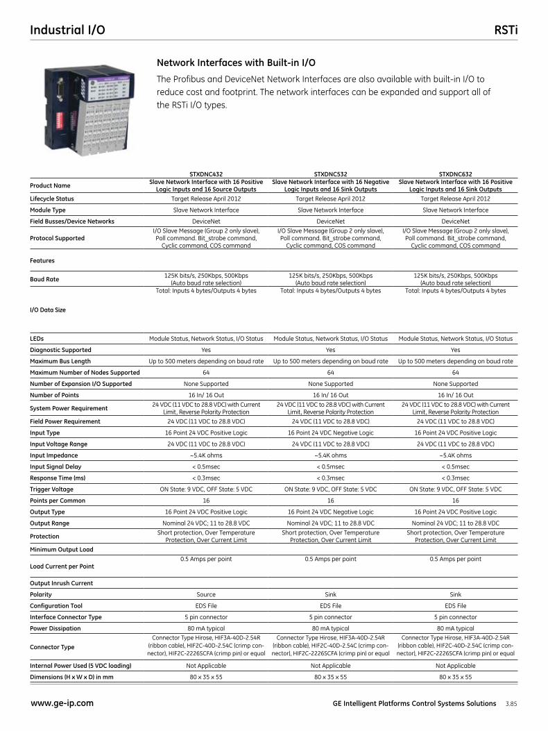
STXDNC432 STXDNC532 STXDNC632
Product Name Slave Network Interface with 16 Positive Logic Inputs and 16 Source Outputs
Slave Network Interface with 16 Negative Logic Inputs and 16 Sink Outputs
Slave Network Interface with 16 Positive Logic Inputs and 16 Sink Outputs
Lifecycle Status Target Release April 2012 Target Release April 2012 Target Release April 2012
Module Type Slave Network Interface Slave Network Interface Slave Network Interface
Field Busses/Device Networks DeviceNet DeviceNet DeviceNet
Protocol SupportedI/O Slave Message (Group 2 only slave), Poll command. Bit_strobe command,
Cyclic command, COS command
I/O Slave Message (Group 2 only slave), Poll command. Bit_strobe command,
Cyclic command, COS command
I/O Slave Message (Group 2 only slave), Poll command. Bit_strobe command,
Cyclic command, COS command
Features
Baud Rate 125K bits/s, 250Kbps, 500Kbps (Auto baud rate selection)
125K bits/s, 250Kbps, 500Kbps (Auto baud rate selection)
125K bits/s, 250Kbps, 500Kbps (Auto baud rate selection)
I/O Data Size
Total: Inputs 4 bytes/Outputs 4 bytes Total: Inputs 4 bytes/Outputs 4 bytes Total: Inputs 4 bytes/Outputs 4 bytes
LEDs Module Status, Network Status, I/O Status Module Status, Network Status, I/O Status Module Status, Network Status, I/O Status
Diagnostic Supported Yes Yes Yes
Maximum Bus Length Up to 500 meters depending on baud rate Up to 500 meters depending on baud rate Up to 500 meters depending on baud rate
Maximum Number of Nodes Supported 64 64 64
Number of Expansion I/O Supported None Supported None Supported None Supported
Number of Points 16 In/ 16 Out 16 In/ 16 Out 16 In/ 16 Out
System Power Requirement 24 VDC (11 VDC to 28.8 VDC) with Current Limit, Reverse Polarity Protection
24 VDC (11 VDC to 28.8 VDC) with Current Limit, Reverse Polarity Protection
24 VDC (11 VDC to 28.8 VDC) with Current Limit, Reverse Polarity Protection
Field Power Requirement 24 VDC (11 VDC to 28.8 VDC) 24 VDC (11 VDC to 28.8 VDC) 24 VDC (11 VDC to 28.8 VDC)
Input Type 16 Point 24 VDC Positive Logic 16 Point 24 VDC Negative Logic 16 Point 24 VDC Positive Logic
Input Voltage Range 24 VDC (11 VDC to 28.8 VDC) 24 VDC (11 VDC to 28.8 VDC) 24 VDC (11 VDC to 28.8 VDC)
Input Impedance ~5.4K ohms ~5.4K ohms ~5.4K ohms
Input Signal Delay < 0.5msec < 0.5msec < 0.5msec
Response Time (ms) < 0.3msec < 0.3msec < 0.3msec
Trigger Voltage ON State: 9 VDC, OFF State: 5 VDC ON State: 9 VDC, OFF State: 5 VDC ON State: 9 VDC, OFF State: 5 VDC
Points per Common 16 16 16
Output Type 16 Point 24 VDC Positive Logic 16 Point 24 VDC Negative Logic 16 Point 24 VDC Positive Logic
Output Range Nominal 24 VDC; 11 to 28.8 VDC Nominal 24 VDC; 11 to 28.8 VDC Nominal 24 VDC; 11 to 28.8 VDC
Protection Short protection, Over Temperature Protection, Over Current Limit
Short protection, Over Temperature Protection, Over Current Limit
Short protection, Over Temperature Protection, Over Current Limit
Minimum Output Load
Load Current per Point0.5 Amps per point 0.5 Amps per point 0.5 Amps per point
Output Inrush Current
Polarity Source Sink Sink
Configuration Tool EDS File EDS File EDS File
Interface Connector Type 5 pin connector 5 pin connector 5 pin connector
Power Dissipation 80 mA typical 80 mA typical 80 mA typical
Connector Type
Connector Type Hirose, HIF3A-40D-2.54R (ribbon cable), HIF2C-40D-2.54C (crimp con-nector), HIF2C-2226SCFA (crimp pin) or equal
Connector Type Hirose, HIF3A-40D-2.54R (ribbon cable), HIF2C-40D-2.54C (crimp con-nector), HIF2C-2226SCFA (crimp pin) or equal
Connector Type Hirose, HIF3A-40D-2.54R (ribbon cable), HIF2C-40D-2.54C (crimp con-nector), HIF2C-2226SCFA (crimp pin) or equal
Internal Power Used (5 VDC loading) Not Applicable Not Applicable Not Applicable
Dimensions (H x W x D) in mm 80 x 35 x 55 80 x 35 x 55 80 x 35 x 55
The Profibus and DeviceNet Network Interfaces are also available with built-in I/O to reduce cost and footprint. The network interfaces can be expanded and support all of the RSTi I/O types.
Network Interfaces with Built-in I/O
RSTi Industrial I/O
3.86 GE Intelligent Platforms Control Systems Solutions www.ge-ip.com
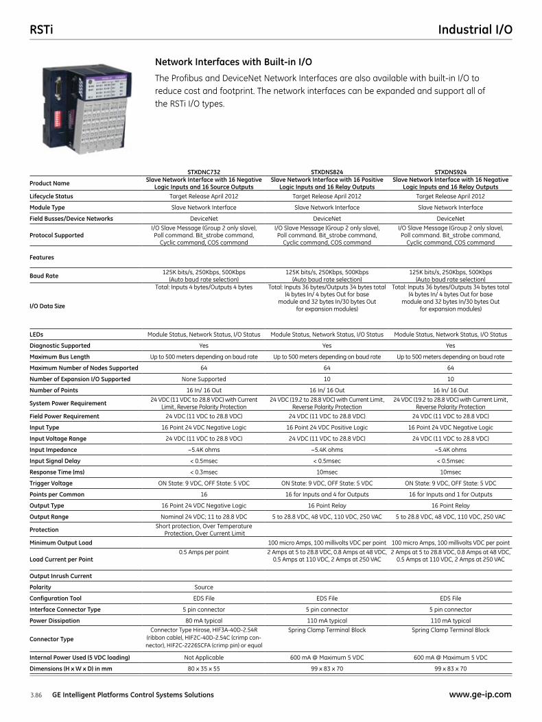
STXDNC732 STXDNS824 STXDNS924
Product Name Slave Network Interface with 16 Negative Logic Inputs and 16 Source Outputs
Slave Network Interface with 16 Positive Logic Inputs and 16 Relay Outputs
Slave Network Interface with 16 Negative Logic Inputs and 16 Relay Outputs
Lifecycle Status Target Release April 2012 Target Release April 2012 Target Release April 2012
Module Type Slave Network Interface Slave Network Interface Slave Network Interface
Field Busses/Device Networks DeviceNet DeviceNet DeviceNet
Protocol SupportedI/O Slave Message (Group 2 only slave), Poll command. Bit_strobe command,
Cyclic command, COS command
I/O Slave Message (Group 2 only slave), Poll command. Bit_strobe command,
Cyclic command, COS command
I/O Slave Message (Group 2 only slave), Poll command. Bit_strobe command,
Cyclic command, COS command
Features
Baud Rate 125K bits/s, 250Kbps, 500Kbps (Auto baud rate selection)
125K bits/s, 250Kbps, 500Kbps (Auto baud rate selection)
125K bits/s, 250Kbps, 500Kbps (Auto baud rate selection)
I/O Data Size
Total: Inputs 4 bytes/Outputs 4 bytes Total: Inputs 36 bytes/Outputs 34 bytes total (4 bytes In/ 4 bytes Out for base
module and 32 bytes In/30 bytes Out for expansion modules)
Total: Inputs 36 bytes/Outputs 34 bytes total (4 bytes In/ 4 bytes Out for base
module and 32 bytes In/30 bytes Out for expansion modules)
LEDs Module Status, Network Status, I/O Status Module Status, Network Status, I/O Status Module Status, Network Status, I/O Status
Diagnostic Supported Yes Yes Yes
Maximum Bus Length Up to 500 meters depending on baud rate Up to 500 meters depending on baud rate Up to 500 meters depending on baud rate
Maximum Number of Nodes Supported 64 64 64
Number of Expansion I/O Supported None Supported 10 10
Number of Points 16 In/ 16 Out 16 In/ 16 Out 16 In/ 16 Out
System Power Requirement 24 VDC (11 VDC to 28.8 VDC) with Current Limit, Reverse Polarity Protection
24 VDC (19.2 to 28.8 VDC) with Current Limit, Reverse Polarity Protection
24 VDC (19.2 to 28.8 VDC) with Current Limit, Reverse Polarity Protection
Field Power Requirement 24 VDC (11 VDC to 28.8 VDC) 24 VDC (11 VDC to 28.8 VDC) 24 VDC (11 VDC to 28.8 VDC)
Input Type 16 Point 24 VDC Negative Logic 16 Point 24 VDC Positive Logic 16 Point 24 VDC Negative Logic
Input Voltage Range 24 VDC (11 VDC to 28.8 VDC) 24 VDC (11 VDC to 28.8 VDC) 24 VDC (11 VDC to 28.8 VDC)
Input Impedance ~5.4K ohms ~5.4K ohms ~5.4K ohms
Input Signal Delay < 0.5msec < 0.5msec < 0.5msec
Response Time (ms) < 0.3msec 10msec 10msec
Trigger Voltage ON State: 9 VDC, OFF State: 5 VDC ON State: 9 VDC, OFF State: 5 VDC ON State: 9 VDC, OFF State: 5 VDC
Points per Common 16 16 for Inputs and 4 for Outputs 16 for Inputs and 1 for Outputs
Output Type 16 Point 24 VDC Negative Logic 16 Point Relay 16 Point Relay
Output Range Nominal 24 VDC; 11 to 28.8 VDC 5 to 28.8 VDC, 48 VDC, 110 VDC, 250 VAC 5 to 28.8 VDC, 48 VDC, 110 VDC, 250 VAC
Protection Short protection, Over Temperature Protection, Over Current Limit
Minimum Output Load 100 micro Amps, 100 millivolts VDC per point 100 micro Amps, 100 millivolts VDC per point
Load Current per Point0.5 Amps per point 2 Amps at 5 to 28.8 VDC, 0.8 Amps at 48 VDC,
0.5 Amps at 110 VDC, 2 Amps at 250 VAC2 Amps at 5 to 28.8 VDC, 0.8 Amps at 48 VDC,
0.5 Amps at 110 VDC, 2 Amps at 250 VAC
Output Inrush Current
Polarity Source
Configuration Tool EDS File EDS File EDS File
Interface Connector Type 5 pin connector 5 pin connector 5 pin connector
Power Dissipation 80 mA typical 110 mA typical 110 mA typical
Connector Type
Connector Type Hirose, HIF3A-40D-2.54R (ribbon cable), HIF2C-40D-2.54C (crimp con-nector), HIF2C-2226SCFA (crimp pin) or equal
Spring Clamp Terminal Block Spring Clamp Terminal Block
Internal Power Used (5 VDC loading) Not Applicable 600 mA @ Maximum 5 VDC 600 mA @ Maximum 5 VDC
Dimensions (H x W x D) in mm 80 x 35 x 55 99 x 83 x 70 99 x 83 x 70
The Profibus and DeviceNet Network Interfaces are also available with built-in I/O to reduce cost and footprint. The network interfaces can be expanded and support all of the RSTi I/O types.
Network Interfaces with Built-in I/O
RSTiIndustrial I/O
3.87www.ge-ip.com GE Intelligent Platforms Control Systems Solutions
STXDNS825 STXDNS925
Product Name Slave Network Interface with 16 Positive Logic Inputs and 16 Isolated Relay Outputs
Slave Network Interface with 16 Negative Logic Inputs and 16 Isolated Relay Outputs
Lifecycle Status Target Release April 2012 Target Release April 2012
Module Type Slave Network Interface Slave Network Interface
Field Busses/Device Networks DeviceNet DeviceNet
Protocol SupportedI/O Slave Message (Group 2 only slave), Poll command. Bit_strobe command,
Cyclic command, COS command
I/O Slave Message (Group 2 only slave), Poll command. Bit_strobe command,
Cyclic command, COS command
Features
Baud Rate 125K bits/s, 250Kbps, 500Kbps (Auto baud rate selection)
125K bits/s, 250Kbps, 500Kbps (Auto baud rate selection)
I/O Data Size
Total: Inputs 36 bytes/Outputs 34 bytes total (4 bytes In/ 4 bytes Out for base
module and 32 bytes In/30 bytes Out for expansion modules)
Total: Inputs 36 bytes/Outputs 34 bytes total (4 bytes In/ 4 bytes Out for base
module and 32 bytes In/30 bytes Out for expansion modules)
LEDs Module Status, Network Status, I/O Status Module Status, Network Status, I/O Status
Diagnostic Supported Yes Yes
Maximum Bus Length Up to 500 meters depending on baud rate Up to 500 meters depending on baud rate
Maximum Number of Nodes Supported 64 64
Number of Expansion I/O Supported 10 10
Number of Points 16 In/ 16 Out 16 In/ 16 Out
System Power Requirement 24 VDC (19.2 to 28.8 VDC) with Current Limit, Reverse Polarity Protection
24 VDC (19.2 to 28.8 VDC) with Current Limit, Reverse Polarity Protection
Field Power Requirement 24 VDC (11 VDC to 28.8 VDC) 24 VDC (11 VDC to 28.8 VDC)
Input Type 16 Point 24 VDC Positive Logic 16 Point 24 VDC Negative Logic
Input Voltage Range 24 VDC (11 VDC to 28.8 VDC) 24 VDC (11 VDC to 28.8 VDC)
Input Impedance ~5.4K ohms ~5.4K ohms
Input Signal Delay < 0.5msec < 0.5msec
Response Time (ms) 10msec 10msec
Trigger Voltage ON State: 9 VDC, OFF State: 5 VDC ON State: 9 VDC, OFF State: 5 VDC
Points per Common 16 for Inputs and 1 for Outputs 16 for Inputs and 1 for Outputs
Output Type 16 Point Isolated Relay 16 Point Isolated Relay
Output Range 5 to 28.8 VDC, 48 VDC, 110 VDC, 250 VAC 5 to 28.8 VDC, 48 VDC, 110 VDC, 250 VAC
Protection
Minimum Output Load 100 micro Amps, 100 millivolts VDC per point 100 micro Amps, 100 millivolts VDC per point
Load Current per Point2 Amps at 5 to 28.8 VDC, 0.8 Amps at 48 VDC,
0.5 Amps at 110 VDC, 2 Amps at 250 VAC2 Amps at 5 to 28.8 VDC, 0.8 Amps at 48 VDC,
0.5 Amps at 110 VDC, 2 Amps at 250 VAC
Output Inrush Current
Polarity
Configuration Tool EDS File EDS File
Interface Connector Type 5 pin connector 5 pin connector
Power Dissipation 110 mA typical 110 mA typical
Connector TypeSpring Clamp Terminal Block Spring Clamp Terminal Block
Internal Power Used (5 VDC loading) 600 mA @ Maximum 5 VDC 600 mA @ Maximum 5 VDC
Dimensions (H x W x D) in mm 99 x 83 x 70 99 x 83 x 70
The Profibus and DeviceNet Network Interfaces are also available with built-in I/O to reduce cost and footprint. The network interfaces can be expanded and support all of the RSTi I/O types.
Network Interfaces with Built-in I/O
RSTi Industrial I/O
3.88 GE Intelligent Platforms Control Systems Solutions www.ge-ip.com
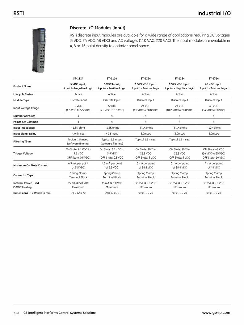
RSTi discrete input modules are available for a wide range of applications requiring DC voltages (5 VDC, 24 VDC, 48 VDC) and AC voltages (110 VAC, 220 VAC). The input modules are available in 4, 8 or 16 point density to optimize panel space.
Discrete I/O Modules (Input)
ST-1124 ST-1114 ST-1214 ST-1224 ST-1314
Product Name5 VDC Input,
4 points Negative Logic5 VDC Input,
4 points Positive Logic12/24 VDC Input,
4 points Positive Logic12/24 VDC Input,
4 points Negative Logic48 VDC Input,
4 points Positive Logic
Lifecycle Status Active Active Active Active Active
Module Type Discrete Input Discrete Input Discrete Input Discrete Input Discrete Input
Input Voltage Range5 VDC
(4.5 VDC to 5.5 VDC)5 VDC
(4.5 VDC to 5.5 VDC)24 VDC
(11 VDC to 28.8 VDC)24 VDC
(10.2 VDC to 28.8 VDC)48 VDC
(34 VDC to 60 VDC)
Number of Points 4 4 4 4 4
Points per Common 4 4 4 4 4
Input Impedance ~1.3K ohms ~1.3K ohms ~5.1K ohms ~5.1K ohms ~12K ohms
Input Signal Delay < 0.5msec < 0.5msec 3.0msec 3.0msec 3.0msec
Filtering TimeTypical 1.5 msec.
(software filtering)Typical 1.5 msec.
(software filtering)Typical 1.5 msec. Typical 1.5 msec.
Trigger VoltageOn State: 2.4 VDC to
5.5 VDC OFF State: 0.8 VDC
On State: 2.4 VDC to 5.5 VDC
OFF State: 0.8 VDC
ON State: 10.2 to 28.8 VDC
OFF State: 5 VDC
ON State: 10.2 to 28.8 VDC
OFF State: 5 VDC
ON State: 48 VDC (34 VDC to 60 VDC) OFF State: 10 VDC
Maximum On State Current4.5 mA per point
at 5.5 VDC4.5 mA per point
at 5.5 VDC6 mA per point
at 28.8 VDC6 mA per point
at 28.8 VDC4 mA per point
at 48 VDC
Connector TypeSpring Clamp
Terminal BlockSpring Clamp
Terminal BlockSpring Clamp
Terminal BlockSpring Clamp
Terminal BlockSpring Clamp
Terminal Block
Internal Power Used (5 VDC loading)
35 mA @ 5.0 VDC Maximum
35 mA @ 5.0 VDC Maximum
35 mA @ 5.0 VDC Maximum
35 mA @ 5.0 VDC Maximum
35 mA @ 5.0 VDC Maximum
Dimensions (H x W x D) in mm 99 x 12 x 70 99 x 12 x 70 99 x 12 x 70 99 x 12 x 70 99 x 12 x 70
RSTiIndustrial I/O
3.89www.ge-ip.com GE Intelligent Platforms Control Systems Solutions
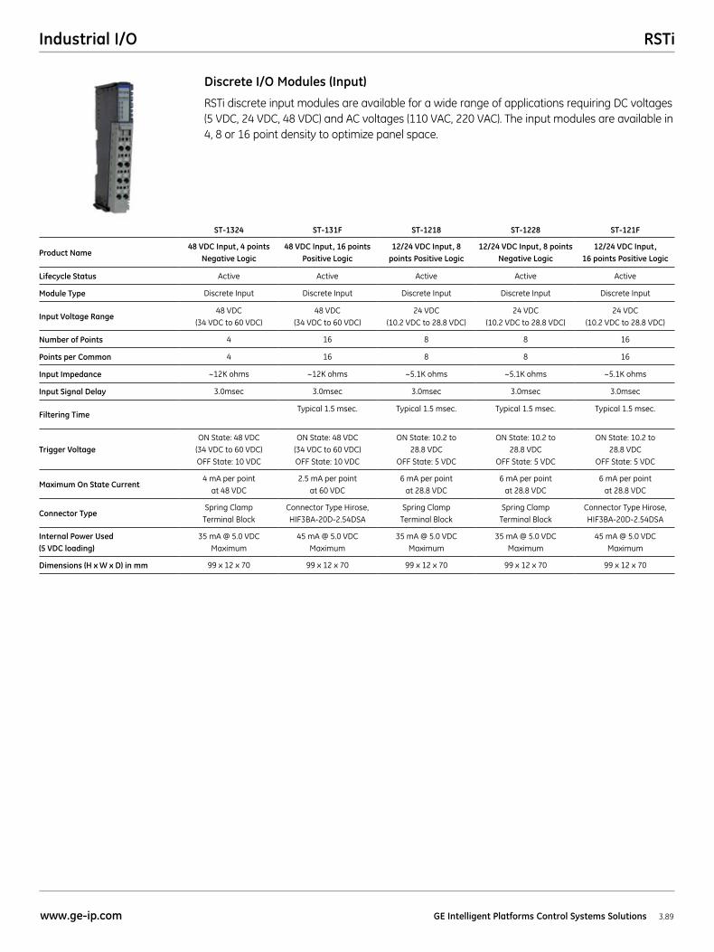
RSTi discrete input modules are available for a wide range of applications requiring DC voltages (5 VDC, 24 VDC, 48 VDC) and AC voltages (110 VAC, 220 VAC). The input modules are available in 4, 8 or 16 point density to optimize panel space.
Discrete I/O Modules (Input)
ST-1324 ST-131F ST-1218 ST-1228 ST-121F
Product Name48 VDC Input, 4 points
Negative Logic48 VDC Input, 16 points
Positive Logic12/24 VDC Input, 8
points Positive Logic12/24 VDC Input, 8 points
Negative Logic12/24 VDC Input,
16 points Positive Logic
Lifecycle Status Active Active Active Active Active
Module Type Discrete Input Discrete Input Discrete Input Discrete Input Discrete Input
Input Voltage Range48 VDC
(34 VDC to 60 VDC)48 VDC
(34 VDC to 60 VDC)24 VDC
(10.2 VDC to 28.8 VDC)24 VDC
(10.2 VDC to 28.8 VDC)24 VDC
(10.2 VDC to 28.8 VDC)
Number of Points 4 16 8 8 16
Points per Common 4 16 8 8 16
Input Impedance ~12K ohms ~12K ohms ~5.1K ohms ~5.1K ohms ~5.1K ohms
Input Signal Delay 3.0msec 3.0msec 3.0msec 3.0msec 3.0msec
Filtering TimeTypical 1.5 msec. Typical 1.5 msec. Typical 1.5 msec. Typical 1.5 msec.
Trigger VoltageON State: 48 VDC
(34 VDC to 60 VDC) OFF State: 10 VDC
ON State: 48 VDC (34 VDC to 60 VDC) OFF State: 10 VDC
ON State: 10.2 to 28.8 VDC
OFF State: 5 VDC
ON State: 10.2 to 28.8 VDC
OFF State: 5 VDC
ON State: 10.2 to 28.8 VDC
OFF State: 5 VDC
Maximum On State Current4 mA per point
at 48 VDC2.5 mA per point
at 60 VDC6 mA per point
at 28.8 VDC6 mA per point
at 28.8 VDC6 mA per point
at 28.8 VDC
Connector TypeSpring Clamp
Terminal BlockConnector Type Hirose, HIF3BA-20D-2.54DSA
Spring Clamp Terminal Block
Spring Clamp Terminal Block
Connector Type Hirose, HIF3BA-20D-2.54DSA
Internal Power Used (5 VDC loading)
35 mA @ 5.0 VDC Maximum
45 mA @ 5.0 VDC Maximum
35 mA @ 5.0 VDC Maximum
35 mA @ 5.0 VDC Maximum
45 mA @ 5.0 VDC Maximum
Dimensions (H x W x D) in mm 99 x 12 x 70 99 x 12 x 70 99 x 12 x 70 99 x 12 x 70 99 x 12 x 70
RSTi Industrial I/O
3.90 GE Intelligent Platforms Control Systems Solutions www.ge-ip.com
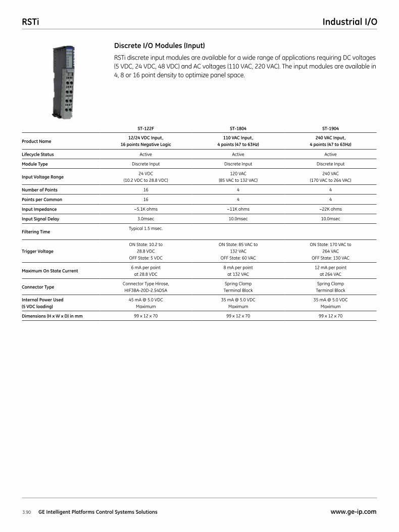
RSTi discrete input modules are available for a wide range of applications requiring DC voltages (5 VDC, 24 VDC, 48 VDC) and AC voltages (110 VAC, 220 VAC). The input modules are available in 4, 8 or 16 point density to optimize panel space.
Discrete I/O Modules (Input)
ST-122F ST-1804 ST-1904
Product Name12/24 VDC Input,
16 points Negative Logic110 VAC Input,
4 points (47 to 63Hz)240 VAC Input,
4 points (47 to 63Hz)
Lifecycle Status Active Active Active
Module Type Discrete Input Discrete Input Discrete Input
Input Voltage Range24 VDC
(10.2 VDC to 28.8 VDC)120 VAC
(85 VAC to 132 VAC)240 VAC
(170 VAC to 264 VAC)
Number of Points 16 4 4
Points per Common 16 4 4
Input Impedance ~5.1K ohms ~11K ohms ~22K ohms
Input Signal Delay 3.0msec 10.0msec 10.0msec
Filtering TimeTypical 1.5 msec.
Trigger VoltageON State: 10.2 to
28.8 VDC OFF State: 5 VDC
ON State: 85 VAC to 132 VAC
OFF State: 60 VAC
ON State: 170 VAC to 264 VAC
OFF State: 130 VAC
Maximum On State Current6 mA per point
at 28.8 VDC8 mA per point
at 132 VAC12 mA per point
at 264 VAC
Connector TypeConnector Type Hirose, HIF3BA-20D-2.54DSA
Spring Clamp Terminal Block
Spring Clamp Terminal Block
Internal Power Used (5 VDC loading)
45 mA @ 5.0 VDC Maximum
35 mA @ 5.0 VDC Maximum
35 mA @ 5.0 VDC Maximum
Dimensions (H x W x D) in mm 99 x 12 x 70 99 x 12 x 70 99 x 12 x 70
RSTiIndustrial I/O
3.91www.ge-ip.com GE Intelligent Platforms Control Systems Solutions
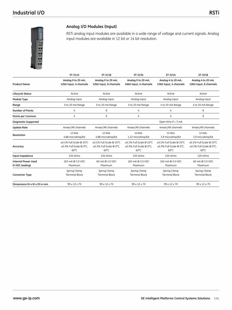
RSTi analog input modules are available in a wide range of voltage and current signals. Analog input modules are available in 12 bit or 14 bit resolution.
Analog I/O Modules (Input)
ST-3114 ST-3118 ST-3134 ST-3214 ST-3218
Product NameAnalog 0 to 20 mA,
12bit Input, 4 channelsAnalog 0 to 20 mA,
12bit Input, 8 channelsAnalog 0 to 20 mA,
14bit Input, 4 channelsAnalog 4 to 20 mA,
12bit Input, 4 channelsAnalog 4 to 20 mA,
12bit Input, 8 channels
Lifecycle Status Active Active Active Active Active
Module Type Analog Input Analog Input Analog Input Analog Input Analog Input
Range 0 to 20 mA Range 0 to 20 mA Range 0 to 20 mA Range 4 to 20 mA Range 4 to 20 mA Range
Number of Points 4 8 4 4 8
Points per Common 4 8 4 4 8
Diagnostic Supported Open Wire if < 3 mA
Update Rate 4msec/All channels 4msec/All channels 4msec/All channels 4msec/All channels 4msec/All channels
Resolution12 bits:
4.88 microAmp/bit12 bits:
4.88 microAmp/bit14 bits:
1.22 microAmp/bit12 bits:
3.9 microAmp/bit12 bits:
3.9 microAmp/bit
Accuracy±0.1% Full Scale @ 25°C ±0.3% Full Scale @ 0°C,
60°C
±0.1% Full Scale @ 25°C ±0.3% Full Scale @ 0°C,
60°C
±0.1% Full Scale @ 25°C ±0.3% Full Scale @ 0°C,
60°C
±0.1% Full Scale @ 25°C ±0.3% Full Scale @ 0°C,
60°C
±0.1% Full Scale @ 25°C ±0.3% Full Scale @ 0°C,
60°C
Input Impedance 120 ohms 120 ohms 120 ohms 120 ohms 120 ohms
Internal Power Used (5 VDC loading)
165 mA @ 5.0 VDC Maximum
60 mA @ 5.0 VDC Maximum
165 mA @ 5.0 VDC Maximum
165 mA @ 5.0 VDC Maximum
60 mA @ 5.0 VDC Maximum
Connector TypeSpring Clamp
Terminal BlockSpring Clamp
Terminal BlockSpring Clamp
Terminal BlockSpring Clamp
Terminal BlockSpring Clamp
Terminal Block
Dimensions (H x W x D) in mm 99 x 12 x 70 99 x 12 x 70 99 x 12 x 70 99 x 12 x 70 99 x 12 x 70
RSTi Industrial I/O
3.92 GE Intelligent Platforms Control Systems Solutions www.ge-ip.com
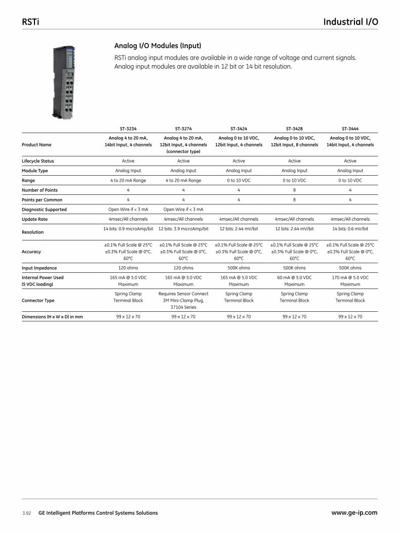
RSTi analog input modules are available in a wide range of voltage and current signals. Analog input modules are available in 12 bit or 14 bit resolution.
Analog I/O Modules (Input)
ST-3234 ST-3274 ST-3424 ST-3428 ST-3444
Product NameAnalog 4 to 20 mA,
14bit Input, 4 channelsAnalog 4 to 20 mA,
12bit Input, 4 channels (connector type)
Analog 0 to 10 VDC, 12bit Input, 4 channels
Analog 0 to 10 VDC, 12bit Input, 8 channels
Analog 0 to 10 VDC, 14bit Input, 4 channels
Lifecycle Status Active Active Active Active Active
Module Type Analog Input Analog Input Analog Input Analog Input Analog Input
Range 4 to 20 mA Range 4 to 20 mA Range 0 to 10 VDC 0 to 10 VDC 0 to 10 VDC
Number of Points 4 4 4 8 4
Points per Common 4 4 4 8 4
Diagnostic Supported Open Wire if < 3 mA Open Wire if < 3 mA
Update Rate 4msec/All channels 4msec/All channels 4msec/All channels 4msec/All channels 4msec/All channels
Resolution14 bits: 0.9 microAmp/bit 12 bits: 3.9 microAmp/bit 12 bits: 2.44 mV/bit 12 bits: 2.44 mV/bit 14 bits: 0.6 mV/bit
Accuracy±0.1% Full Scale @ 25°C ±0.3% Full Scale @ 0°C,
60°C
±0.1% Full Scale @ 25°C ±0.3% Full Scale @ 0°C,
60°C
±0.1% Full Scale @ 25°C ±0.3% Full Scale @ 0°C,
60°C
±0.1% Full Scale @ 25°C ±0.3% Full Scale @ 0°C,
60°C
±0.1% Full Scale @ 25°C ±0.3% Full Scale @ 0°C,
60°C
Input Impedance 120 ohms 120 ohms 500K ohms 500K ohms 500K ohms
Internal Power Used (5 VDC loading)
165 mA @ 5.0 VDC Maximum
165 mA @ 5.0 VDC Maximum
165 mA @ 5.0 VDC Maximum
60 mA @ 5.0 VDC Maximum
170 mA @ 5.0 VDC Maximum
Connector TypeSpring Clamp
Terminal BlockRequires Sensor Connect
3M Mini-Clamp Plug, 37104 Series
Spring Clamp Terminal Block
Spring Clamp Terminal Block
Spring Clamp Terminal Block
Dimensions (H x W x D) in mm 99 x 12 x 70 99 x 12 x 70 99 x 12 x 70 99 x 12 x 70 99 x 12 x 70
RSTiIndustrial I/O
3.93www.ge-ip.com GE Intelligent Platforms Control Systems Solutions
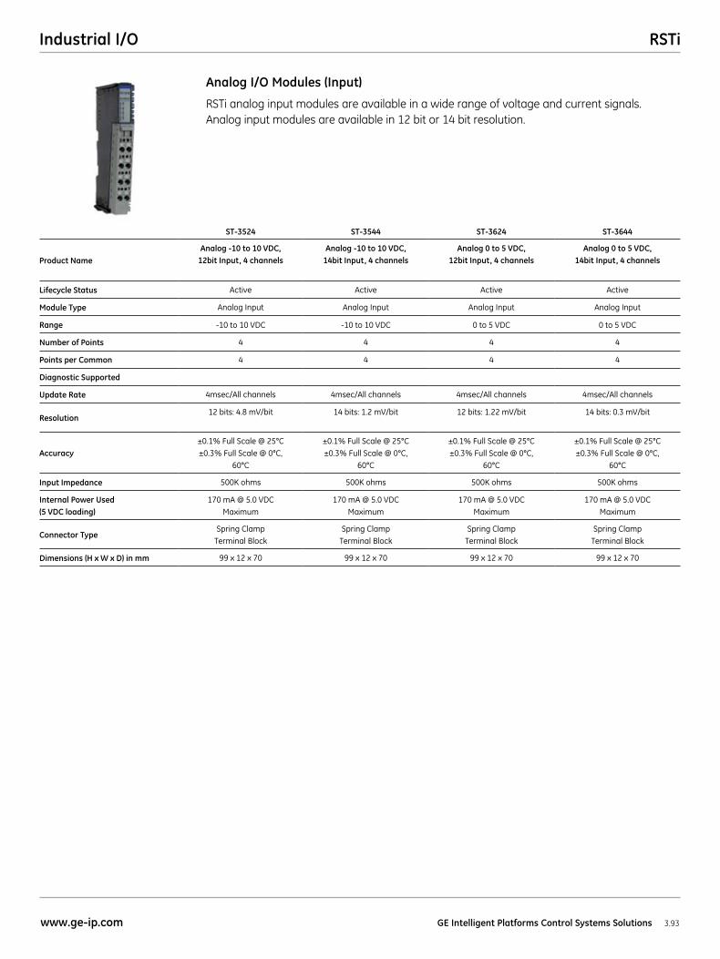
RSTi analog input modules are available in a wide range of voltage and current signals. Analog input modules are available in 12 bit or 14 bit resolution.
Analog I/O Modules (Input)
ST-3524 ST-3544 ST-3624 ST-3644
Product NameAnalog -10 to 10 VDC,
12bit Input, 4 channelsAnalog -10 to 10 VDC,
14bit Input, 4 channelsAnalog 0 to 5 VDC,
12bit Input, 4 channelsAnalog 0 to 5 VDC,
14bit Input, 4 channels
Lifecycle Status Active Active Active Active
Module Type Analog Input Analog Input Analog Input Analog Input
Range -10 to 10 VDC -10 to 10 VDC 0 to 5 VDC 0 to 5 VDC
Number of Points 4 4 4 4
Points per Common 4 4 4 4
Diagnostic Supported
Update Rate 4msec/All channels 4msec/All channels 4msec/All channels 4msec/All channels
Resolution12 bits: 4.8 mV/bit 14 bits: 1.2 mV/bit 12 bits: 1.22 mV/bit 14 bits: 0.3 mV/bit
Accuracy±0.1% Full Scale @ 25°C ±0.3% Full Scale @ 0°C,
60°C
±0.1% Full Scale @ 25°C ±0.3% Full Scale @ 0°C,
60°C
±0.1% Full Scale @ 25°C ±0.3% Full Scale @ 0°C,
60°C
±0.1% Full Scale @ 25°C ±0.3% Full Scale @ 0°C,
60°C
Input Impedance 500K ohms 500K ohms 500K ohms 500K ohms
Internal Power Used (5 VDC loading)
170 mA @ 5.0 VDC Maximum
170 mA @ 5.0 VDC Maximum
170 mA @ 5.0 VDC Maximum
170 mA @ 5.0 VDC Maximum
Connector TypeSpring Clamp
Terminal BlockSpring Clamp
Terminal BlockSpring Clamp
Terminal BlockSpring Clamp
Terminal Block
Dimensions (H x W x D) in mm 99 x 12 x 70 99 x 12 x 70 99 x 12 x 70 99 x 12 x 70
RSTi Industrial I/O
3.94 GE Intelligent Platforms Control Systems Solutions www.ge-ip.com
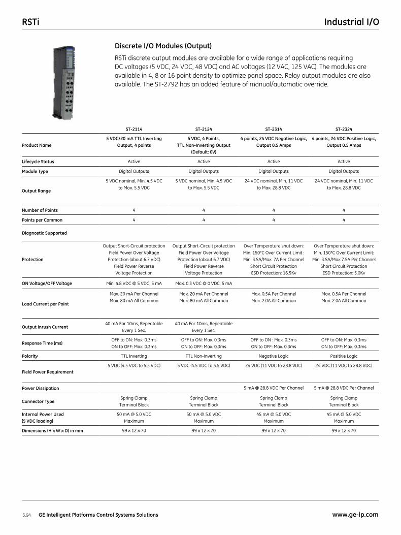
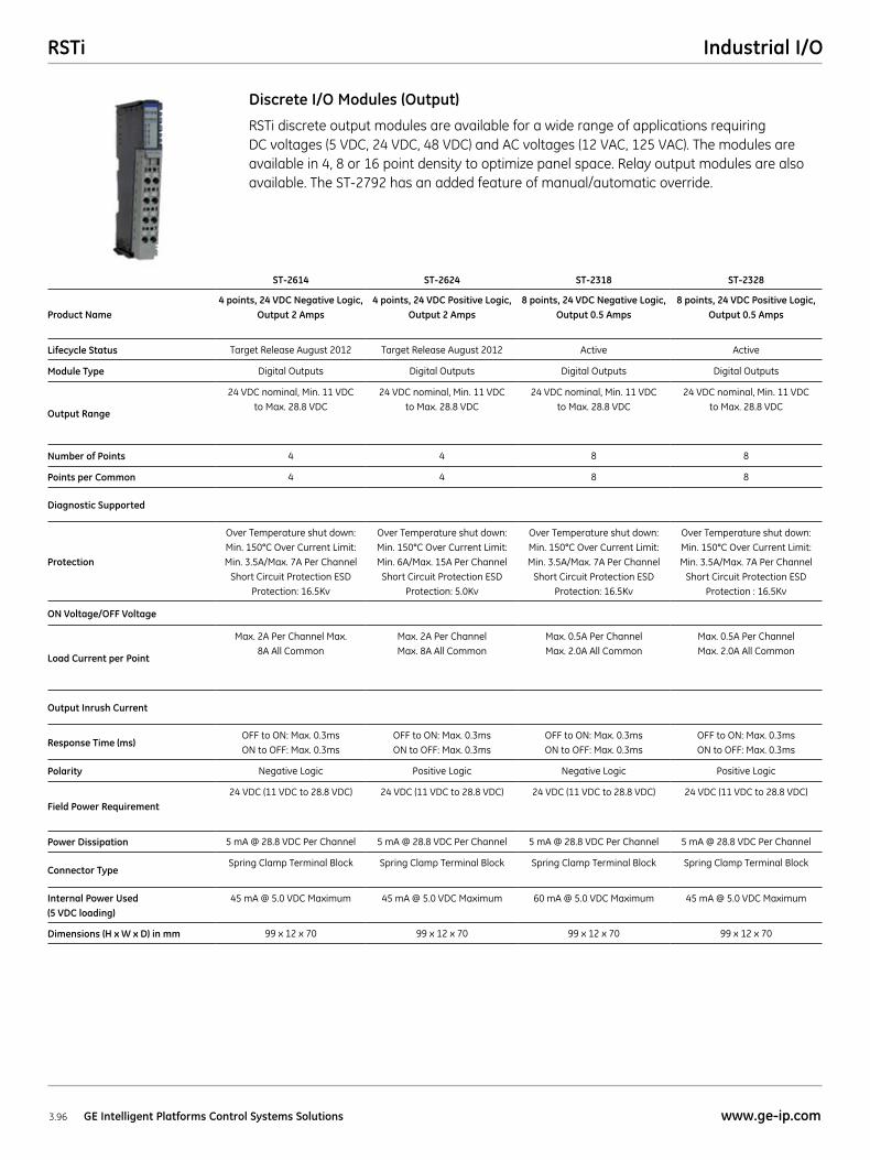
RSTi discrete output modules are available for a wide range of applications requiring DC voltages (5 VDC, 24 VDC, 48 VDC) and AC voltages (12 VAC, 125 VAC). The modules are available in 4, 8 or 16 point density to optimize panel space. Relay output modules are also available. The ST-2792 has an added feature of manual/automatic override.
Discrete I/O Modules (Output)
ST-2114 ST-2124 ST-2314 ST-2324
Product Name5 VDC/20 mA TTL Inverting
Output, 4 points5 VDC, 4 Points,
TTL Non-Inverting Output (Default: 0V)
4 points, 24 VDC Negative Logic, Output 0.5 Amps
4 points, 24 VDC Positive Logic, Output 0.5 Amps
Lifecycle Status Active Active Active Active
Module Type Digital Outputs Digital Outputs Digital Outputs Digital Outputs
Output Range
5 VDC nominal, Min. 4.5 VDC to Max. 5.5 VDC
5 VDC nominal, Min. 4.5 VDC to Max. 5.5 VDC
24 VDC nominal, Min. 11 VDC to Max. 28.8 VDC
24 VDC nominal, Min. 11 VDC to Max. 28.8 VDC
Number of Points 4 4 4 4
Points per Common 4 4 4 4
Diagnostic Supported
Protection
Output Short-Circuit protection Field Power Over Voltage
Protection (about 6.7 VDC) Field Power Reverse Voltage Protection
Output Short-Circuit protection Field Power Over Voltage
Protection (about 6.7 VDC) Field Power Reverse Voltage Protection
Over Temperature shut down: Min. 150°C Over Current Limit : Min. 3.5A/Max. 7A Per Channel
Short Circuit Protection ESD Protection: 16.5Kv
Over Temperature shut down: Min. 150°C Over Current Limit:
Min. 3.5A/Max.7.5A Per Channel Short Circuit Protection ESD Protection: 5.0Kv
ON Voltage/OFF Voltage Min. 4.8 VDC @ 5 VDC, 5 mA Max. 0.3 VDC @ 0 VDC, 5 mA
Load Current per Point
Max. 20 mA Per Channel Max. 80 mA All Common
Max. 20 mA Per Channel Max. 80 mA All Common
Max. 0.5A Per Channel Max. 2.0A All Common
Max. 0.5A Per Channel Max. 2.0A All Common
Output Inrush Current40 mA For 10ms, Repeatable
Every 1 Sec.40 mA For 10ms, Repeatable
Every 1 Sec.
Response Time (ms)OFF to ON: Max. 0.3ms ON to OFF: Max. 0.3ms
OFF to ON: Max. 0.3ms ON to OFF: Max. 0.3ms
OFF to ON : Max. 0.3ms ON to OFF: Max. 0.3ms
OFF to ON: Max. 0.3ms ON to OFF: Max. 0.3ms
Polarity TTL Inverting TTL Non-Inverting Negative Logic Positive Logic
Field Power Requirement5 VDC (4.5 VDC to 5.5 VDC) 5 VDC (4.5 VDC to 5.5 VDC) 24 VDC (11 VDC to 28.8 VDC) 24 VDC (11 VDC to 28.8 VDC)
Power Dissipation 5 mA @ 28.8 VDC Per Channel 5 mA @ 28.8 VDC Per Channel
Connector TypeSpring Clamp
Terminal BlockSpring Clamp
Terminal BlockSpring Clamp
Terminal BlockSpring Clamp
Terminal Block
Internal Power Used (5 VDC loading)
50 mA @ 5.0 VDC Maximum
50 mA @ 5.0 VDC Maximum
45 mA @ 5.0 VDC Maximum
45 mA @ 5.0 VDC Maximum
Dimensions (H x W x D) in mm 99 x 12 x 70 99 x 12 x 70 99 x 12 x 70 99 x 12 x 70

RSTiIndustrial I/O
3.95www.ge-ip.com GE Intelligent Platforms Control Systems Solutions
RSTi discrete output modules are available for a wide range of applications requiring DC voltages (5 VDC, 24 VDC, 48 VDC) and AC voltages (12 VAC, 125 VAC). The modules are available in 4, 8 or 16 point density to optimize panel space. Relay output modules are also available. The ST-2792 has an added feature of manual/automatic override.
Discrete I/O Modules (Output)
ST-2414 ST-2424 ST-2514 ST-2524
Product Name4 points, 24 VDC Negative
Logic, Output 0.5 Amps with Diagnostics
4 points, 24 VDC Positive Logic, Output 0.5 Amps with
Diagnostics
4 points, 24 VDC Negative Logic, Output 2 Amps with
Diagnostics
4 points, 24 VDC Positive Logic, Output 2 Amps with
Diagnostics
Lifecycle Status Active Active Active Active
Module Type Digital Outputs Digital Outputs Digital Outputs Digital Outputs
Output Range
24 VDC nominal, Min. 11 VDC to Max. 28.8 VDC
24 VDC nominal, Min. 11 VDC to Max. 28.8 VDC
24 VDC nominal, Min. 11 VDC to Max. 28.8 VDC
24 VDC nominal, Min. 11 VDC to Max. 28.8 VDC
Number of Points 4 4 4 4
Points per Common 4 4 4 4
Diagnostic SupportedPoint Fault Reported to
Network InterfacePoint Fault Reported to
Network InterfacePoint Fault Reported to
Network InterfacePoint Fault Reported to
Network Interface
Protection
Over Temperature shut down: Min. 150°C Over Current Limit: Min. 3.5A/Max. 7A Per Channel
Short Circuit Protection ESD Protection: 16.5Kv
Over Temperature shut down: Min. 150°C Over Current Limit:
Min. 3.5A/Max.7.5A Per Channel Short Circuit Protection ESD Protection: 5.0Kv
Over Temperature shut down: Min. 150°C Over Current Limit: Min. 3.5A/Max. 7A Per Channel
Short Circuit Protection ESD Protection: 16.5Kv
Over Temperature shut down: Min. 150°C Over Current Limit: Min. 6A/Max. 15A Per Channel
Short Circuit Protection ESD Protection: 5.0Kv
ON Voltage/OFF Voltage
Load Current per Point
Max. 0.5A Per Channel Max. 2.0A All Common
Max. 0.5A Per Channel Max. 2.0A All Common
Max. 2A Per Channel Max. 8A All Common
Max. 2A Per Channel Max. 8A All Common
Output Inrush Current
Response Time (ms)OFF to ON: Max. 0.3ms ON to OFF: Max. 0.3ms
OFF to ON: Max. 0.3ms ON to OFF: Max. 0.3ms
OFF to ON: Max. 0.3ms ON to OFF: Max. 0.3ms
OFF to ON : Max. 0.3ms ON to OFF: Max. 0.3ms
Polarity Negative Logic Positive Logic Negative Logic Positive Logic
Field Power Requirement24 VDC (11 VDC to 28.8 VDC) 24 VDC (11 VDC to 28.8 VDC) 24 VDC (11 VDC to 28.8 VDC) 24 VDC (11 VDC to 28.8 VDC)
Power Dissipation 5 mA @ 28.8 VDC Per Channel 5 mA @ 28.8 VDC Per Channel 5 mA @ 28.8 VDC Per Channel 5 mA @ 28.8 VDC Per Channel
Connector TypeSpring Clamp
Terminal BlockSpring Clamp
Terminal BlockSpring Clamp
Terminal BlockSpring Clamp
Terminal Block
Internal Power Used (5 VDC loading)
45 mA @ 5.0 VDC Maximum
45 mA @ 5.0 VDC Maximum
45 mA @ 5.0 VDC Maximum
45 mA @ 5.0 VDC Maximum
Dimensions (H x W x D) in mm 99 x 12 x 70 99 x 12 x 70 99 x 12 x 70 99 x 12 x 70
RSTi Industrial I/O
3.96 GE Intelligent Platforms Control Systems Solutions www.ge-ip.com
RSTi discrete output modules are available for a wide range of applications requiring DC voltages (5 VDC, 24 VDC, 48 VDC) and AC voltages (12 VAC, 125 VAC). The modules are available in 4, 8 or 16 point density to optimize panel space. Relay output modules are also available. The ST-2792 has an added feature of manual/automatic override.
Discrete I/O Modules (Output)
ST-2614 ST-2624 ST-2318 ST-2328
Product Name4 points, 24 VDC Negative Logic,
Output 2 Amps 4 points, 24 VDC Positive Logic,
Output 2 Amps 8 points, 24 VDC Negative Logic,
Output 0.5 Amps8 points, 24 VDC Positive Logic,
Output 0.5 Amps
Lifecycle Status Target Release August 2012 Target Release August 2012 Active Active
Module Type Digital Outputs Digital Outputs Digital Outputs Digital Outputs
Output Range
24 VDC nominal, Min. 11 VDC to Max. 28.8 VDC
24 VDC nominal, Min. 11 VDC to Max. 28.8 VDC
24 VDC nominal, Min. 11 VDC to Max. 28.8 VDC
24 VDC nominal, Min. 11 VDC to Max. 28.8 VDC
Number of Points 4 4 8 8
Points per Common 4 4 8 8
Diagnostic Supported
Protection
Over Temperature shut down: Min. 150°C Over Current Limit: Min. 3.5A/Max. 7A Per Channel
Short Circuit Protection ESD Protection: 16.5Kv
Over Temperature shut down: Min. 150°C Over Current Limit: Min. 6A/Max. 15A Per Channel
Short Circuit Protection ESD Protection: 5.0Kv
Over Temperature shut down: Min. 150°C Over Current Limit: Min. 3.5A/Max. 7A Per Channel
Short Circuit Protection ESD Protection: 16.5Kv
Over Temperature shut down: Min. 150°C Over Current Limit: Min. 3.5A/Max. 7A Per Channel
Short Circuit Protection ESD Protection : 16.5Kv
ON Voltage/OFF Voltage
Load Current per Point
Max. 2A Per Channel Max. 8A All Common
Max. 2A Per Channel Max. 8A All Common
Max. 0.5A Per Channel Max. 2.0A All Common
Max. 0.5A Per Channel Max. 2.0A All Common
Output Inrush Current
Response Time (ms)OFF to ON: Max. 0.3ms ON to OFF: Max. 0.3ms
OFF to ON: Max. 0.3ms ON to OFF: Max. 0.3ms
OFF to ON: Max. 0.3ms ON to OFF: Max. 0.3ms
OFF to ON: Max. 0.3ms ON to OFF: Max. 0.3ms
Polarity Negative Logic Positive Logic Negative Logic Positive Logic
Field Power Requirement24 VDC (11 VDC to 28.8 VDC) 24 VDC (11 VDC to 28.8 VDC) 24 VDC (11 VDC to 28.8 VDC) 24 VDC (11 VDC to 28.8 VDC)
Power Dissipation 5 mA @ 28.8 VDC Per Channel 5 mA @ 28.8 VDC Per Channel 5 mA @ 28.8 VDC Per Channel 5 mA @ 28.8 VDC Per Channel
Connector TypeSpring Clamp Terminal Block Spring Clamp Terminal Block Spring Clamp Terminal Block Spring Clamp Terminal Block
Internal Power Used (5 VDC loading)
45 mA @ 5.0 VDC Maximum 45 mA @ 5.0 VDC Maximum 60 mA @ 5.0 VDC Maximum 45 mA @ 5.0 VDC Maximum
Dimensions (H x W x D) in mm 99 x 12 x 70 99 x 12 x 70 99 x 12 x 70 99 x 12 x 70
RSTiIndustrial I/O
3.97www.ge-ip.com GE Intelligent Platforms Control Systems Solutions
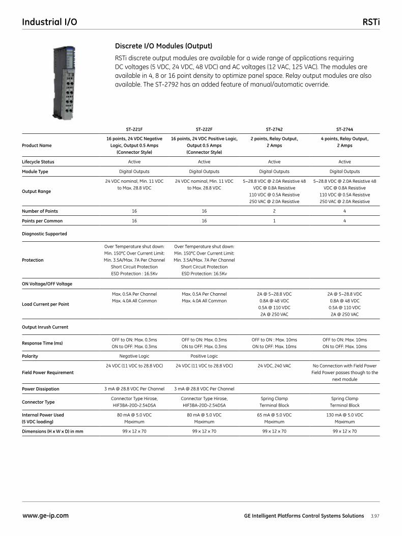
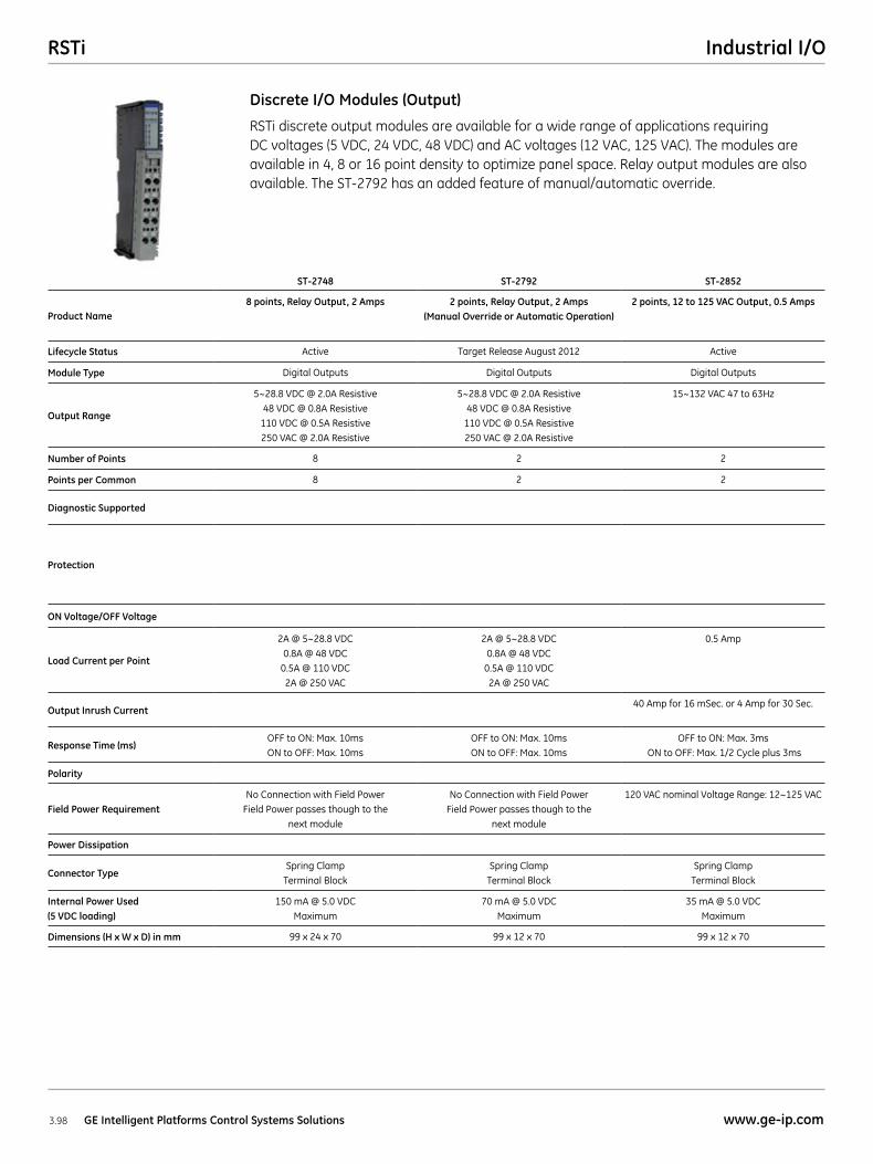
RSTi discrete output modules are available for a wide range of applications requiring DC voltages (5 VDC, 24 VDC, 48 VDC) and AC voltages (12 VAC, 125 VAC). The modules are available in 4, 8 or 16 point density to optimize panel space. Relay output modules are also available. The ST-2792 has an added feature of manual/automatic override.
ST-221F ST-222F ST-2742 ST-2744
Product Name16 points, 24 VDC Negative
Logic, Output 0.5 Amps (Connector Style)
16 points, 24 VDC Positive Logic, Output 0.5 Amps (Connector Style)
2 points, Relay Output, 2 Amps
4 points, Relay Output, 2 Amps
Lifecycle Status Active Active Active Active
Module Type Digital Outputs Digital Outputs Digital Outputs Digital Outputs
Output Range
24 VDC nominal, Min. 11 VDC to Max. 28.8 VDC
24 VDC nominal, Min. 11 VDC to Max. 28.8 VDC
5~28.8 VDC @ 2.0A Resistive 48 VDC @ 0.8A Resistive
110 VDC @ 0.5A Resistive 250 VAC @ 2.0A Resistive
5~28.8 VDC @ 2.0A Resistive 48 VDC @ 0.8A Resistive
110 VDC @ 0.5A Resistive 250 VAC @ 2.0A Resistive
Number of Points 16 16 2 4
Points per Common 16 16 1 4
Diagnostic Supported
Protection
Over Temperature shut down: Min. 150°C Over Current Limit: Min. 3.5A/Max. 7A Per Channel
Short Circuit Protection ESD Protection : 16.5Kv
Over Temperature shut down: Min. 150°C Over Current Limit: Min. 3.5A/Max. 7A Per Channel
Short Circuit Protection ESD Protection: 16.5Kv
ON Voltage/OFF Voltage
Load Current per Point
Max. 0.5A Per Channel Max. 4.0A All Common
Max. 0.5A Per Channel Max. 4.0A All Common
2A @ 5~28.8 VDC 0.8A @ 48 VDC
0.5A @ 110 VDC 2A @ 250 VAC
2A @ 5~28.8 VDC 0.8A @ 48 VDC
0.5A @ 110 VDC 2A @ 250 VAC
Output Inrush Current
Response Time (ms)OFF to ON: Max. 0.3ms ON to OFF: Max. 0.3ms
OFF to ON: Max. 0.3ms ON to OFF: Max. 0.3ms
OFF to ON : Max. 10ms ON to OFF: Max. 10ms
OFF to ON: Max. 10ms ON to OFF: Max. 10ms
Polarity Negative Logic Positive Logic
Field Power Requirement24 VDC (11 VDC to 28.8 VDC) 24 VDC (11 VDC to 28.8 VDC) 24 VDC, 240 VAC No Connection with Field Power
Field Power passes though to the next module
Power Dissipation 3 mA @ 28.8 VDC Per Channel 3 mA @ 28.8 VDC Per Channel
Connector TypeConnector Type Hirose, HIF3BA-20D-2.54DSA
Connector Type Hirose, HIF3BA-20D-2.54DSA
Spring Clamp Terminal Block
Spring Clamp Terminal Block
Internal Power Used (5 VDC loading)
80 mA @ 5.0 VDC Maximum
80 mA @ 5.0 VDC Maximum
65 mA @ 5.0 VDC Maximum
130 mA @ 5.0 VDC Maximum
Dimensions (H x W x D) in mm 99 x 12 x 70 99 x 12 x 70 99 x 12 x 70 99 x 12 x 70
Discrete I/O Modules (Output)
RSTi Industrial I/O
3.98 GE Intelligent Platforms Control Systems Solutions www.ge-ip.com
RSTi discrete output modules are available for a wide range of applications requiring DC voltages (5 VDC, 24 VDC, 48 VDC) and AC voltages (12 VAC, 125 VAC). The modules are available in 4, 8 or 16 point density to optimize panel space. Relay output modules are also available. The ST-2792 has an added feature of manual/automatic override.
ST-2748 ST-2792 ST-2852
Product Name8 points, Relay Output, 2 Amps 2 points, Relay Output, 2 Amps
(Manual Override or Automatic Operation)2 points, 12 to 125 VAC Output, 0.5 Amps
Lifecycle Status Active Target Release August 2012 Active
Module Type Digital Outputs Digital Outputs Digital Outputs
Output Range
5~28.8 VDC @ 2.0A Resistive 48 VDC @ 0.8A Resistive
110 VDC @ 0.5A Resistive 250 VAC @ 2.0A Resistive
5~28.8 VDC @ 2.0A Resistive 48 VDC @ 0.8A Resistive
110 VDC @ 0.5A Resistive 250 VAC @ 2.0A Resistive
15~132 VAC 47 to 63Hz
Number of Points 8 2 2
Points per Common 8 2 2
Diagnostic Supported
Protection
ON Voltage/OFF Voltage
Load Current per Point
2A @ 5~28.8 VDC 0.8A @ 48 VDC
0.5A @ 110 VDC 2A @ 250 VAC
2A @ 5~28.8 VDC 0.8A @ 48 VDC
0.5A @ 110 VDC 2A @ 250 VAC
0.5 Amp
Output Inrush Current40 Amp for 16 mSec. or 4 Amp for 30 Sec.
Response Time (ms)OFF to ON: Max. 10ms ON to OFF: Max. 10ms
OFF to ON: Max. 10ms ON to OFF: Max. 10ms
OFF to ON: Max. 3ms ON to OFF: Max. 1/2 Cycle plus 3ms
Polarity
Field Power RequirementNo Connection with Field Power
Field Power passes though to the next module
No Connection with Field Power Field Power passes though to the
next module
120 VAC nominal Voltage Range: 12~125 VAC
Power Dissipation
Connector TypeSpring Clamp
Terminal BlockSpring Clamp
Terminal BlockSpring Clamp
Terminal Block
Internal Power Used (5 VDC loading)
150 mA @ 5.0 VDC Maximum
70 mA @ 5.0 VDC Maximum
35 mA @ 5.0 VDC Maximum
Dimensions (H x W x D) in mm 99 x 24 x 70 99 x 12 x 70 99 x 12 x 70
Discrete I/O Modules (Output)
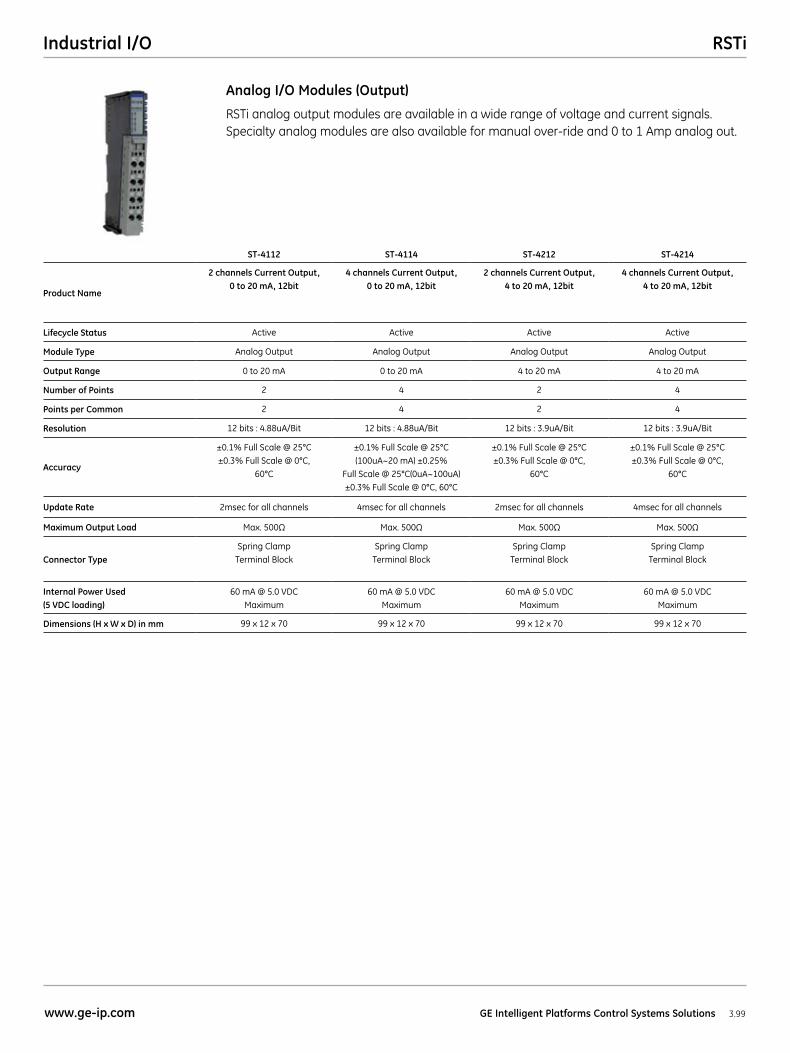
RSTiIndustrial I/O
3.99www.ge-ip.com GE Intelligent Platforms Control Systems Solutions
RSTi analog output modules are available in a wide range of voltage and current signals. Specialty analog modules are also available for manual over-ride and 0 to 1 Amp analog out.
Analog I/O Modules (Output)
ST-4112 ST-4114 ST-4212 ST-4214
Product Name
2 channels Current Output, 0 to 20 mA, 12bit
4 channels Current Output, 0 to 20 mA, 12bit
2 channels Current Output, 4 to 20 mA, 12bit
4 channels Current Output, 4 to 20 mA, 12bit
Lifecycle Status Active Active Active Active
Module Type Analog Output Analog Output Analog Output Analog Output
Output Range 0 to 20 mA 0 to 20 mA 4 to 20 mA 4 to 20 mA
Number of Points 2 4 2 4
Points per Common 2 4 2 4
Resolution 12 bits : 4.88uA/Bit 12 bits : 4.88uA/Bit 12 bits : 3.9uA/Bit 12 bits : 3.9uA/Bit
Accuracy
±0.1% Full Scale @ 25°C ±0.3% Full Scale @ 0°C,
60°C
±0.1% Full Scale @ 25°C (100uA~20 mA) ±0.25%
Full Scale @ 25°C(0uA~100uA) ±0.3% Full Scale @ 0°C, 60°C
±0.1% Full Scale @ 25°C ±0.3% Full Scale @ 0°C,
60°C
±0.1% Full Scale @ 25°C ±0.3% Full Scale @ 0°C,
60°C
Update Rate 2msec for all channels 4msec for all channels 2msec for all channels 4msec for all channels
Maximum Output Load Max. 500Ω Max. 500Ω Max. 500Ω Max. 500Ω
Connector TypeSpring Clamp
Terminal BlockSpring Clamp
Terminal BlockSpring Clamp
Terminal BlockSpring Clamp
Terminal Block
Internal Power Used (5 VDC loading)
60 mA @ 5.0 VDC Maximum
60 mA @ 5.0 VDC Maximum
60 mA @ 5.0 VDC Maximum
60 mA @ 5.0 VDC Maximum
Dimensions (H x W x D) in mm 99 x 12 x 70 99 x 12 x 70 99 x 12 x 70 99 x 12 x 70
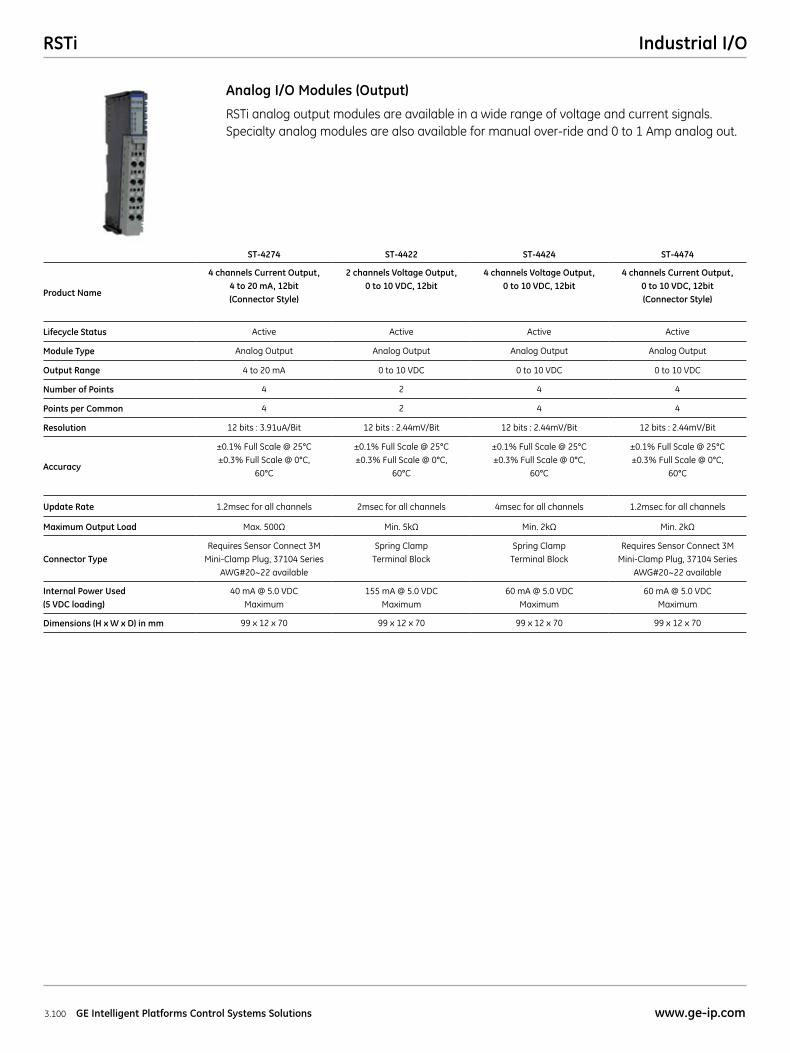
RSTi Industrial I/O
3.100 GE Intelligent Platforms Control Systems Solutions www.ge-ip.com
ST-4274 ST-4422 ST-4424 ST-4474
Product Name
4 channels Current Output, 4 to 20 mA, 12bit (Connector Style)
2 channels Voltage Output, 0 to 10 VDC, 12bit
4 channels Voltage Output, 0 to 10 VDC, 12bit
4 channels Current Output, 0 to 10 VDC, 12bit (Connector Style)
Lifecycle Status Active Active Active Active
Module Type Analog Output Analog Output Analog Output Analog Output
Output Range 4 to 20 mA 0 to 10 VDC 0 to 10 VDC 0 to 10 VDC
Number of Points 4 2 4 4
Points per Common 4 2 4 4
Resolution 12 bits : 3.91uA/Bit 12 bits : 2.44mV/Bit 12 bits : 2.44mV/Bit 12 bits : 2.44mV/Bit
Accuracy
±0.1% Full Scale @ 25°C ±0.3% Full Scale @ 0°C,
60°C
±0.1% Full Scale @ 25°C ±0.3% Full Scale @ 0°C,
60°C
±0.1% Full Scale @ 25°C ±0.3% Full Scale @ 0°C,
60°C
±0.1% Full Scale @ 25°C ±0.3% Full Scale @ 0°C,
60°C
Update Rate 1.2msec for all channels 2msec for all channels 4msec for all channels 1.2msec for all channels
Maximum Output Load Max. 500Ω Min. 5kΩ Min. 2kΩ Min. 2kΩ
Connector TypeRequires Sensor Connect 3M
Mini-Clamp Plug, 37104 Series AWG#20~22 available
Spring Clamp Terminal Block
Spring Clamp Terminal Block
Requires Sensor Connect 3M Mini-Clamp Plug, 37104 Series
AWG#20~22 available
Internal Power Used (5 VDC loading)
40 mA @ 5.0 VDC Maximum
155 mA @ 5.0 VDC Maximum
60 mA @ 5.0 VDC Maximum
60 mA @ 5.0 VDC Maximum
Dimensions (H x W x D) in mm 99 x 12 x 70 99 x 12 x 70 99 x 12 x 70 99 x 12 x 70
RSTi analog output modules are available in a wide range of voltage and current signals. Specialty analog modules are also available for manual over-ride and 0 to 1 Amp analog out.
Analog I/O Modules (Output)
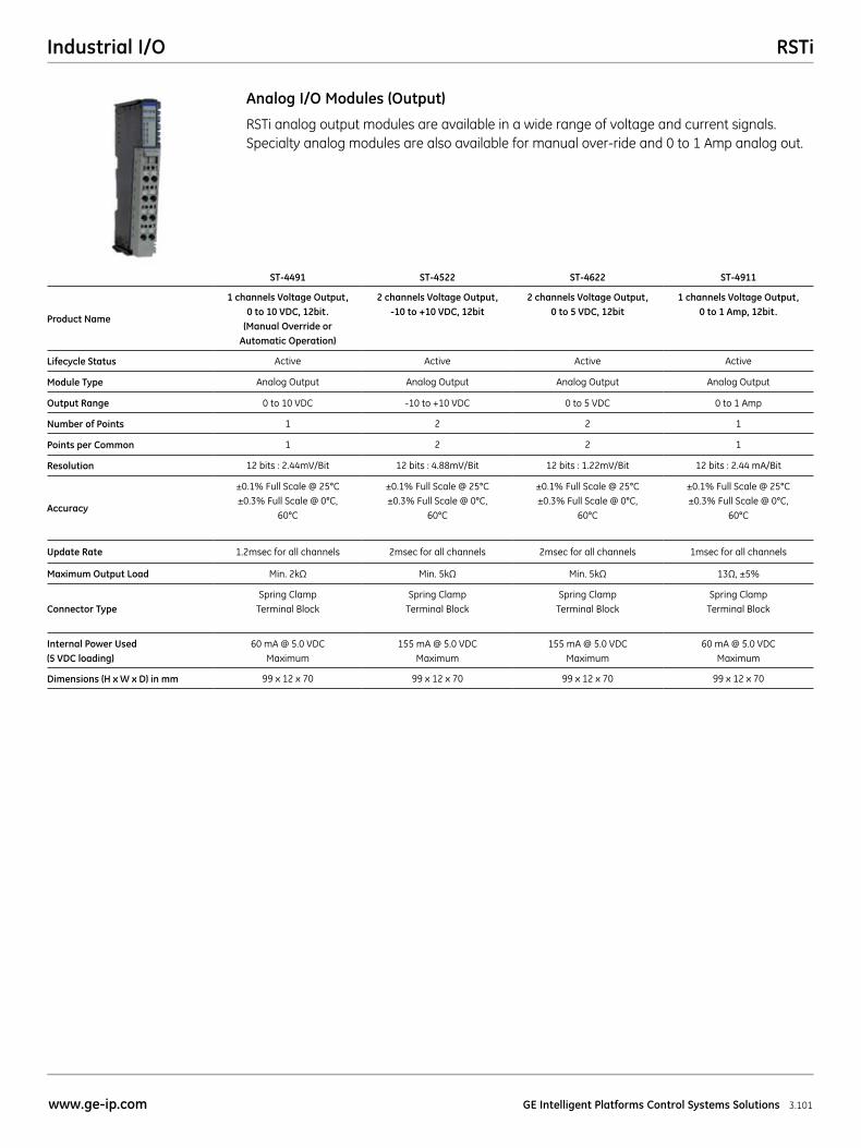
RSTiIndustrial I/O
3.101www.ge-ip.com GE Intelligent Platforms Control Systems Solutions
ST-4491 ST-4522 ST-4622 ST-4911
Product Name
1 channels Voltage Output, 0 to 10 VDC, 12bit.
(Manual Override or Automatic Operation)
2 channels Voltage Output, -10 to +10 VDC, 12bit
2 channels Voltage Output, 0 to 5 VDC, 12bit
1 channels Voltage Output, 0 to 1 Amp, 12bit.
Lifecycle Status Active Active Active Active
Module Type Analog Output Analog Output Analog Output Analog Output
Output Range 0 to 10 VDC -10 to +10 VDC 0 to 5 VDC 0 to 1 Amp
Number of Points 1 2 2 1
Points per Common 1 2 2 1
Resolution 12 bits : 2.44mV/Bit 12 bits : 4.88mV/Bit 12 bits : 1.22mV/Bit 12 bits : 2.44 mA/Bit
Accuracy
±0.1% Full Scale @ 25°C ±0.3% Full Scale @ 0°C,
60°C
±0.1% Full Scale @ 25°C ±0.3% Full Scale @ 0°C,
60°C
±0.1% Full Scale @ 25°C ±0.3% Full Scale @ 0°C,
60°C
±0.1% Full Scale @ 25°C ±0.3% Full Scale @ 0°C,
60°C
Update Rate 1.2msec for all channels 2msec for all channels 2msec for all channels 1msec for all channels
Maximum Output Load Min. 2kΩ Min. 5kΩ Min. 5kΩ 13Ω, ±5%
Connector TypeSpring Clamp
Terminal BlockSpring Clamp
Terminal BlockSpring Clamp
Terminal BlockSpring Clamp
Terminal Block
Internal Power Used (5 VDC loading)
60 mA @ 5.0 VDC Maximum
155 mA @ 5.0 VDC Maximum
155 mA @ 5.0 VDC Maximum
60 mA @ 5.0 VDC Maximum
Dimensions (H x W x D) in mm 99 x 12 x 70 99 x 12 x 70 99 x 12 x 70 99 x 12 x 70
RSTi analog output modules are available in a wide range of voltage and current signals. Specialty analog modules are also available for manual over-ride and 0 to 1 Amp analog out.
Analog I/O Modules (Output)
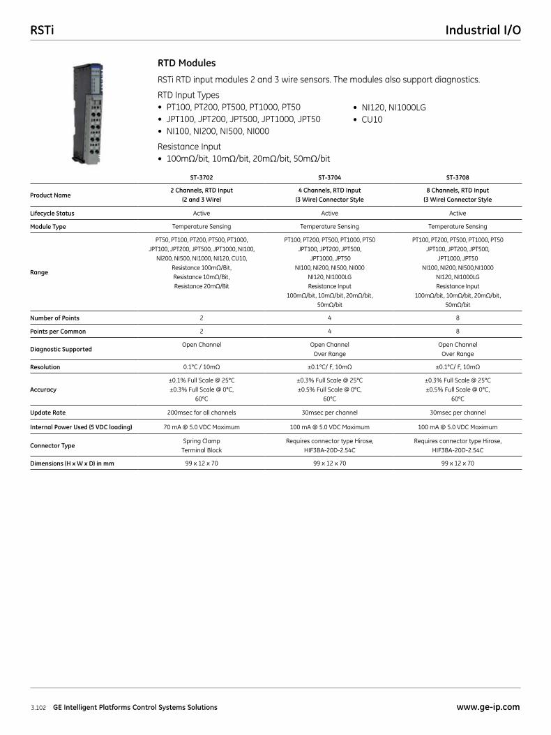
RSTi Industrial I/O
3.102 GE Intelligent Platforms Control Systems Solutions www.ge-ip.com
RSTi RTD input modules 2 and 3 wire sensors. The modules also support diagnostics.
RTD Input Types• PT100,PT200,PT500,PT1000,PT50• JPT100,JPT200,JPT500,JPT1000,JPT50• NI100,NI200,NI500,NI000
Resistance Input• 100mΩ/bit, 10mΩ/bit, 20mΩ/bit, 50mΩ/bit
RTD Modules
• NI120,NI1000LG• CU10
ST-3702 ST-3704 ST-3708
Product Name2 Channels, RTD Input
(2 and 3 Wire)4 Channels, RTD Input
(3 Wire) Connector Style8 Channels, RTD Input
(3 Wire) Connector Style
Lifecycle Status Active Active Active
Module Type Temperature Sensing Temperature Sensing Temperature Sensing
Range
PT50, PT100, PT200, PT500, PT1000, JPT100, JPT200, JPT500, JPT1000, NI100,
Nl200, NI500, NI1000, NI120, CU10, Resistance 100mΩ/Bit, Resistance 10mΩ/Bit, Resistance 20mΩ/Bit
PT100, PT200, PT500, PT1000, PT50 JPT100, JPT200, JPT500,
JPT1000, JPT50 NI100, NI200, NI500, NI000
NI120, NI1000LG Resistance Input
100mΩ/bit, 10mΩ/bit, 20mΩ/bit, 50mΩ/bit
PT100, PT200, PT500, PT1000, PT50 JPT100, JPT200, JPT500,
JPT1000, JPT50 NI100, NI200, NI500,NI1000
NI120, NI1000LG Resistance Input
100mΩ/bit, 10mΩ/bit, 20mΩ/bit, 50mΩ/bit
Number of Points 2 4 8
Points per Common 2 4 8
Diagnostic SupportedOpen Channel Open Channel
Over RangeOpen Channel
Over Range
Resolution 0.1°C / 10mΩ ±0.1°C/ F, 10mΩ ±0.1°C/ F, 10mΩ
Accuracy±0.1% Full Scale @ 25°C ±0.3% Full Scale @ 0°C,
60°C
±0.3% Full Scale @ 25°C ±0.5% Full Scale @ 0°C,
60°C
±0.3% Full Scale @ 25°C ±0.5% Full Scale @ 0°C,
60°C
Update Rate 200msec for all channels 30msec per channel 30msec per channel
Internal Power Used (5 VDC loading) 70 mA @ 5.0 VDC Maximum 100 mA @ 5.0 VDC Maximum 100 mA @ 5.0 VDC Maximum
Connector TypeSpring Clamp
Terminal BlockRequires connector type Hirose,
HIF3BA-20D-2.54CRequires connector type Hirose,
HIF3BA-20D-2.54C
Dimensions (H x W x D) in mm 99 x 12 x 70 99 x 12 x 70 99 x 12 x 70
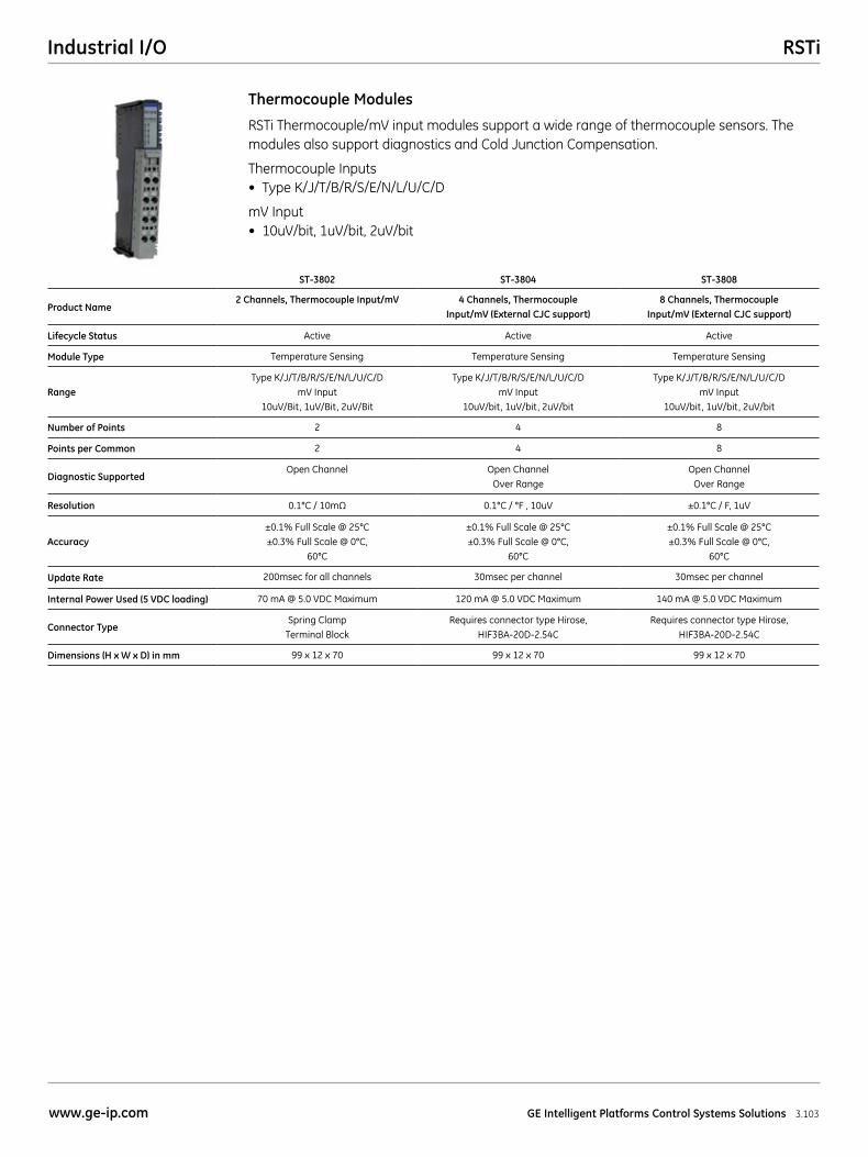
RSTiIndustrial I/O
3.103www.ge-ip.com GE Intelligent Platforms Control Systems Solutions
RSTi Thermocouple/mV input modules support a wide range of thermocouple sensors. The modules also support diagnostics and Cold Junction Compensation.
Thermocouple Inputs• TypeK/J/T/B/R/S/E/N/L/U/C/D
mV Input• 10uV/bit,1uV/bit,2uV/bit
Thermocouple Modules
ST-3802 ST-3804 ST-3808
Product Name2 Channels, Thermocouple Input/mV 4 Channels, Thermocouple
Input/mV (External CJC support)8 Channels, Thermocouple
Input/mV (External CJC support)
Lifecycle Status Active Active Active
Module Type Temperature Sensing Temperature Sensing Temperature Sensing
Range Type K/J/T/B/R/S/E/N/L/U/C/D
mV Input 10uV/Bit, 1uV/Bit, 2uV/Bit
Type K/J/T/B/R/S/E/N/L/U/C/D mV Input
10uV/bit, 1uV/bit, 2uV/bit
Type K/J/T/B/R/S/E/N/L/U/C/D mV Input
10uV/bit, 1uV/bit, 2uV/bit
Number of Points 2 4 8
Points per Common 2 4 8
Diagnostic SupportedOpen Channel Open Channel
Over RangeOpen Channel
Over Range
Resolution 0.1°C / 10mΩ 0.1°C / °F , 10uV ±0.1°C / F, 1uV
Accuracy±0.1% Full Scale @ 25°C ±0.3% Full Scale @ 0°C,
60°C
±0.1% Full Scale @ 25°C ±0.3% Full Scale @ 0°C,
60°C
±0.1% Full Scale @ 25°C ±0.3% Full Scale @ 0°C,
60°C
Update Rate 200msec for all channels 30msec per channel 30msec per channel
Internal Power Used (5 VDC loading) 70 mA @ 5.0 VDC Maximum 120 mA @ 5.0 VDC Maximum 140 mA @ 5.0 VDC Maximum
Connector TypeSpring Clamp
Terminal BlockRequires connector type Hirose,
HIF3BA-20D-2.54CRequires connector type Hirose,
HIF3BA-20D-2.54C
Dimensions (H x W x D) in mm 99 x 12 x 70 99 x 12 x 70 99 x 12 x 70
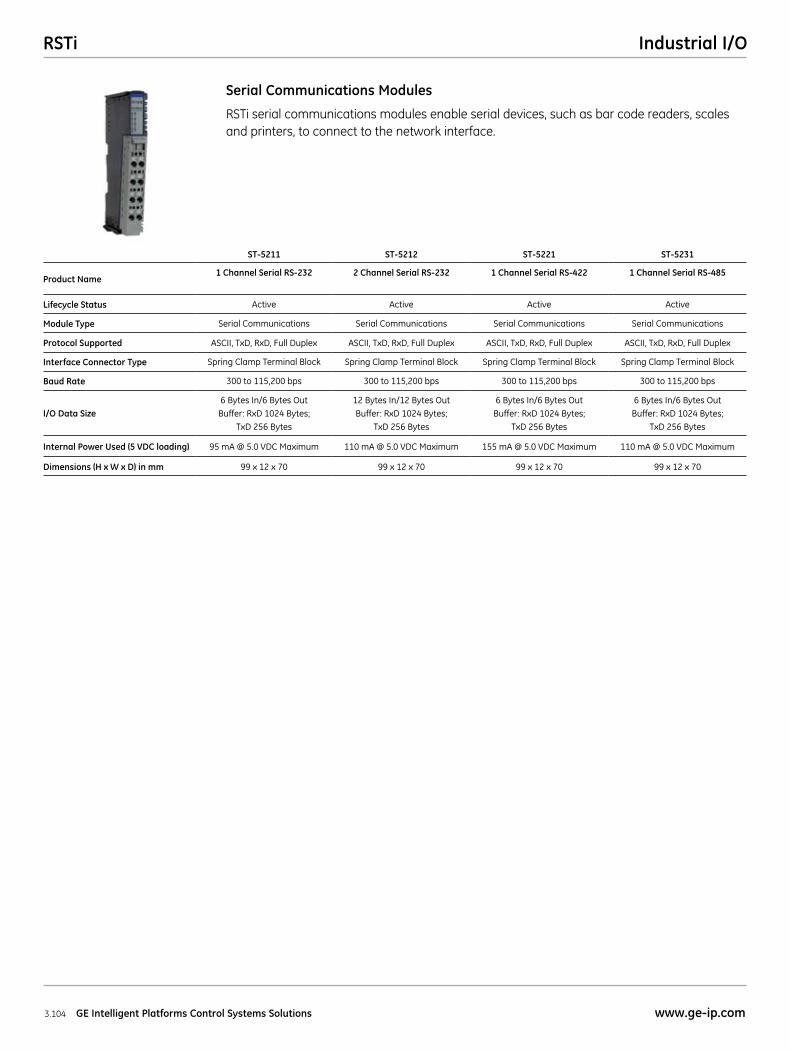
RSTi Industrial I/O
3.104 GE Intelligent Platforms Control Systems Solutions www.ge-ip.com
RSTi serial communications modules enable serial devices, such as bar code readers, scales and printers, to connect to the network interface.
Serial Communications Modules
ST-5211 ST-5212 ST-5221 ST-5231
Product Name1 Channel Serial RS-232 2 Channel Serial RS-232 1 Channel Serial RS-422 1 Channel Serial RS-485
Lifecycle Status Active Active Active Active
Module Type Serial Communications Serial Communications Serial Communications Serial Communications
Protocol Supported ASCII, TxD, RxD, Full Duplex ASCII, TxD, RxD, Full Duplex ASCII, TxD, RxD, Full Duplex ASCII, TxD, RxD, Full Duplex
Interface Connector Type Spring Clamp Terminal Block Spring Clamp Terminal Block Spring Clamp Terminal Block Spring Clamp Terminal Block
Baud Rate 300 to 115,200 bps 300 to 115,200 bps 300 to 115,200 bps 300 to 115,200 bps
I/O Data Size6 Bytes In/6 Bytes Out
Buffer: RxD 1024 Bytes; TxD 256 Bytes
12 Bytes In/12 Bytes Out Buffer: RxD 1024 Bytes;
TxD 256 Bytes
6 Bytes In/6 Bytes Out Buffer: RxD 1024 Bytes;
TxD 256 Bytes
6 Bytes In/6 Bytes Out Buffer: RxD 1024 Bytes;
TxD 256 Bytes
Internal Power Used (5 VDC loading) 95 mA @ 5.0 VDC Maximum 110 mA @ 5.0 VDC Maximum 155 mA @ 5.0 VDC Maximum 110 mA @ 5.0 VDC Maximum
Dimensions (H x W x D) in mm 99 x 12 x 70 99 x 12 x 70 99 x 12 x 70 99 x 12 x 70
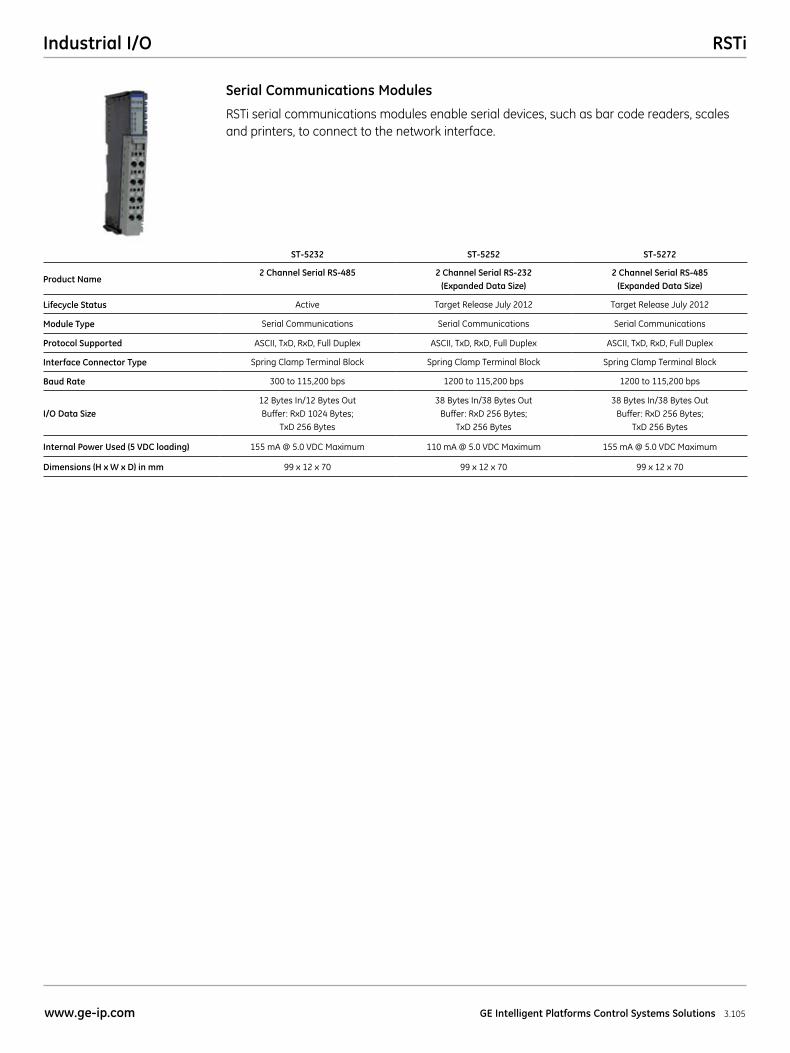
RSTiIndustrial I/O
3.105www.ge-ip.com GE Intelligent Platforms Control Systems Solutions
RSTi serial communications modules enable serial devices, such as bar code readers, scales and printers, to connect to the network interface.
Serial Communications Modules
ST-5232 ST-5252 ST-5272
Product Name2 Channel Serial RS-485 2 Channel Serial RS-232
(Expanded Data Size)2 Channel Serial RS-485
(Expanded Data Size)
Lifecycle Status Active Target Release July 2012 Target Release July 2012
Module Type Serial Communications Serial Communications Serial Communications
Protocol Supported ASCII, TxD, RxD, Full Duplex ASCII, TxD, RxD, Full Duplex ASCII, TxD, RxD, Full Duplex
Interface Connector Type Spring Clamp Terminal Block Spring Clamp Terminal Block Spring Clamp Terminal Block
Baud Rate 300 to 115,200 bps 1200 to 115,200 bps 1200 to 115,200 bps
I/O Data Size12 Bytes In/12 Bytes Out Buffer: RxD 1024 Bytes;
TxD 256 Bytes
38 Bytes In/38 Bytes Out Buffer: RxD 256 Bytes;
TxD 256 Bytes
38 Bytes In/38 Bytes Out Buffer: RxD 256 Bytes;
TxD 256 Bytes
Internal Power Used (5 VDC loading) 155 mA @ 5.0 VDC Maximum 110 mA @ 5.0 VDC Maximum 155 mA @ 5.0 VDC Maximum
Dimensions (H x W x D) in mm 99 x 12 x 70 99 x 12 x 70 99 x 12 x 70
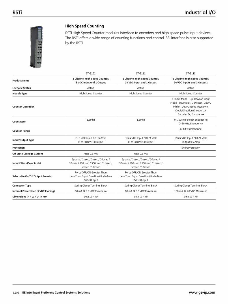
RSTi Industrial I/O
3.106 GE Intelligent Platforms Control Systems Solutions www.ge-ip.com
RSTi High Speed Counter modules interface to encoders and high speed pulse input devices. The RSTi offers a wide range of counting functions and control. SSI interface is also supported by the RSTi.
High Speed Counting
ST-5101 ST-5111 ST-5112
Product Name1 Channel High Speed Counter,
5 VDC Input and 1 Output1 Channel High Speed Counter,
24 VDC Input and 1 Output2 Channel High Speed Counter, 24 VDC Inputs and 2 Outputs
Lifecycle Status Active Active Active
Module Type High Speed Counter High Speed Counter High Speed Counter
Counter Operation
1-Input Mode - Up, Down 2-Input Mode - Up/Inhibit, Up/Reset, Down/
Inhibit, Down/Reset, Up/Down, Clock/Direction Encoder 1x,
Encoder 2x, Encoder 4x
Count Rate1.5Mhz 1.5Mhz 0~100KHz except Encoder 4x
0~50KHz, Encoder 4x
Counter Range32 bit wide/channel
Input/Output Type(1) 5 VDC Input / (1) 24 VDC
(5 to 28.8 VDC) Output(1) 24 VDC Input / (1) 24 VDC
(5 to 28.8 VDC) Output(2) 24 VDC Input / (2) 24 VDC
Output 0.5 Amp
Protection Short Protection
Off State Leakage Current Max. 0.5 mA Max. 0.5 mA
Input Filters (Selectable)Bypass / 1usec / 5usec / 10usec /
50usec / 100usec / 500usec / 1msec / 5msec / 10msec
Bypass / 1usec / 5usec / 10usec / 50usec / 100usec / 500usec / 1msec /
5msec / 10msec
Selectable On/Off Output PresetsForce OFF/ON Greater Than
Less Than Equal Overflow/Underflow PWM Output
Force OFF/ON Greater Than Less Than Equal Overflow/Underflow
PWM Output
Connector Type Spring Clamp Terminal Block Spring Clamp Terminal Block Spring Clamp Terminal Block
Internal Power Used (5 VDC loading) 80 mA @ 5.0 VDC Maximum 80 mA @ 5.0 VDC Maximum 160 mA @ 5.0 VDC Maximum
Dimensions (H x W x D) in mm 99 x 12 x 70 99 x 12 x 70 99 x 12 x 70
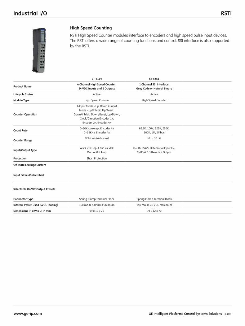
RSTiIndustrial I/O
3.107www.ge-ip.com GE Intelligent Platforms Control Systems Solutions
RSTi High Speed Counter modules interface to encoders and high speed pulse input devices. The RSTi offers a wide range of counting functions and control. SSI interface is also supported by the RSTi.
High Speed Counting
ST-5114 ST-5351
Product Name4 Channel High Speed Counter, 24 VDC Inputs and 2 Outputs
1 Channel SSI Interface. Gray Code or Natural Binary
Lifecycle Status Active Active
Module Type High Speed Counter High Speed Counter
Counter Operation
1-Input Mode - Up, Down 2-Input Mode - Up/Inhibit, Up/Reset,
Down/Inhibit, Down/Reset, Up/Down, Clock/Direction Encoder 1x,
Encoder 2x, Encoder 4x
Count Rate0~50KHz except Encoder 4x
0~25KHz, Encoder 4x62.5K, 100K, 125K, 250K,
500K, 1M, 2Mbps
Counter Range32 bit wide/channel Max. 30 bit
Input/Output Type(4) 24 VDC Input / (2) 24 VDC
Output 0.5 AmpD+, D- RS422 Differential Input C+,
C- RS422 Differential Output
Protection Short Protection
Off State Leakage Current
Input Filters (Selectable)
Selectable On/Off Output Presets
Connector Type Spring Clamp Terminal Block Spring Clamp Terminal Block
Internal Power Used (5VDC loading) 160 mA @ 5.0 VDC Maximum 150 mA @ 5.0 VDC Maximum
Dimensions (H x W x D) in mm 99 x 12 x 70 99 x 12 x 70
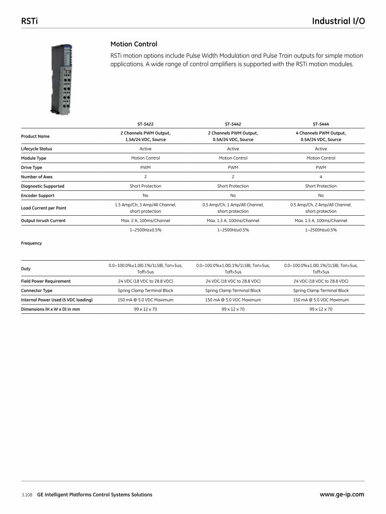
RSTi Industrial I/O
3.108 GE Intelligent Platforms Control Systems Solutions www.ge-ip.com
RSTi motion options include Pulse Width Modulation and Pulse Train outputs for simple motion applications. A wide range of control amplifiers is supported with the RSTi motion modules.
Motion Control
ST-5422 ST-5442 ST-5444
Product Name2 Channels PWM Output,
1.5A/24 VDC, Source2 Channels PWM Output,
0.5A/24 VDC, Source4 Channels PWM Output,
0.5A/24 VDC, Source
Lifecycle Status Active Active Active
Module Type Motion Control Motion Control Motion Control
Drive Type PWM PWM PWM
Number of Axes 2 2 4
Diagnostic Supported Short Protection Short Protection Short Protection
Encoder Support No No No
Load Current per Point1.5 Amp/Ch, 3 Amp/All Channel,
short protection0.5 Amp/Ch, 1 Amp/All Channel,
short protection0.5 Amp/Ch, 2 Amp/All Channel,
short protection
Output Inrush Current Max. 2 A, 100ms/Channel Max. 1.5 A, 100ms/Channel Max. 1.5 A, 100ms/Channel
Frequency
1~2500Hz±0.5% 1~2500Hz±0.5% 1~2500Hz±0.5%
Duty0.0~100.0%±1.0(0.1%/1LSB), Ton>5us,
Toff>5us0.0~100.0%±1.0(0.1%/1LSB), Ton>5us,
Toff>5us0.0~100.0%±1.0(0.1%/1LSB), Ton>5us,
Toff>5us
Field Power Requirement 24 VDC (18 VDC to 28.8 VDC) 24 VDC (18 VDC to 28.8 VDC) 24 VDC (18 VDC to 28.8 VDC)
Connector Type Spring Clamp Terminal Block Spring Clamp Terminal Block Spring Clamp Terminal Block
Internal Power Used (5 VDC loading) 150 mA @ 5.0 VDC Maximum 150 mA @ 5.0 VDC Maximum 150 mA @ 5.0 VDC Maximum
Dimensions (H x W x D) in mm 99 x 12 x 70 99 x 12 x 70 99 x 12 x 70
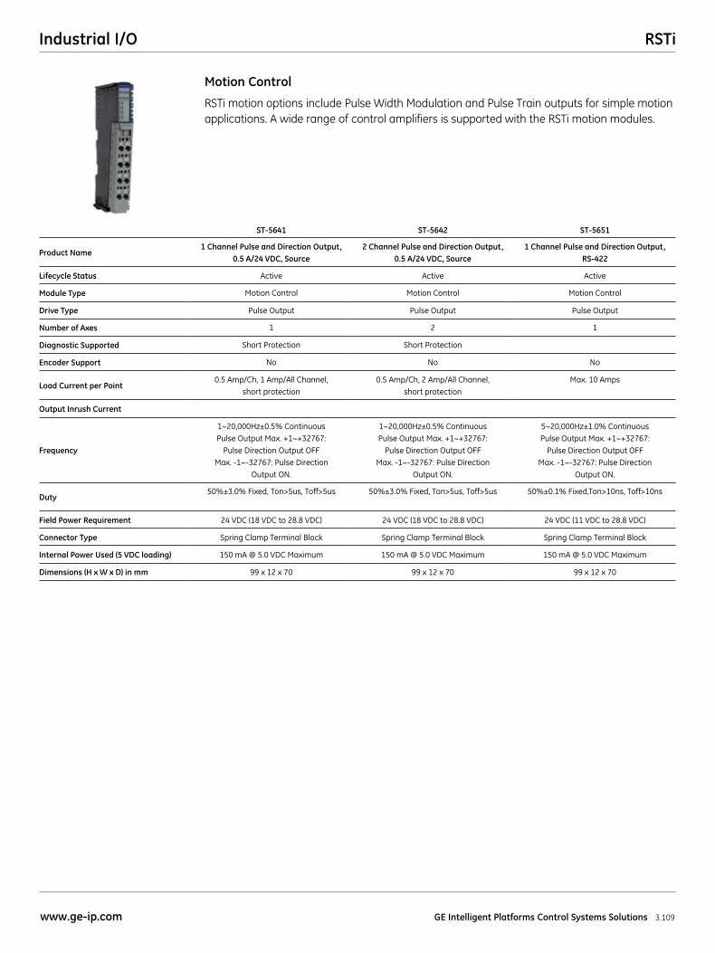
RSTiIndustrial I/O
3.109www.ge-ip.com GE Intelligent Platforms Control Systems Solutions
RSTi motion options include Pulse Width Modulation and Pulse Train outputs for simple motion applications. A wide range of control amplifiers is supported with the RSTi motion modules.
Motion Control
ST-5641 ST-5642 ST-5651
Product Name1 Channel Pulse and Direction Output,
0.5 A/24 VDC, Source2 Channel Pulse and Direction Output,
0.5 A/24 VDC, Source1 Channel Pulse and Direction Output,
RS-422
Lifecycle Status Active Active Active
Module Type Motion Control Motion Control Motion Control
Drive Type Pulse Output Pulse Output Pulse Output
Number of Axes 1 2 1
Diagnostic Supported Short Protection Short Protection
Encoder Support No No No
Load Current per Point0.5 Amp/Ch, 1 Amp/All Channel,
short protection0.5 Amp/Ch, 2 Amp/All Channel,
short protectionMax. 10 Amps
Output Inrush Current
Frequency
1~20,000Hz±0.5% Continuous Pulse Output Max. +1~+32767:
Pulse Direction Output OFF Max. -1~-32767: Pulse Direction
Output ON.
1~20,000Hz±0.5% Continuous Pulse Output Max. +1~+32767:
Pulse Direction Output OFF Max. -1~-32767: Pulse Direction
Output ON.
5~20,000Hz±1.0% Continuous Pulse Output Max. +1~+32767:
Pulse Direction Output OFF Max. -1~-32767: Pulse Direction
Output ON.
Duty50%±3.0% Fixed, Ton>5us, Toff>5us 50%±3.0% Fixed, Ton>5us, Toff>5us 50%±0.1% Fixed,Ton>10ns, Toff>10ns
Field Power Requirement 24 VDC (18 VDC to 28.8 VDC) 24 VDC (18 VDC to 28.8 VDC) 24 VDC (11 VDC to 28.8 VDC)
Connector Type Spring Clamp Terminal Block Spring Clamp Terminal Block Spring Clamp Terminal Block
Internal Power Used (5 VDC loading) 150 mA @ 5.0 VDC Maximum 150 mA @ 5.0 VDC Maximum 150 mA @ 5.0 VDC Maximum
Dimensions (H x W x D) in mm 99 x 12 x 70 99 x 12 x 70 99 x 12 x 70
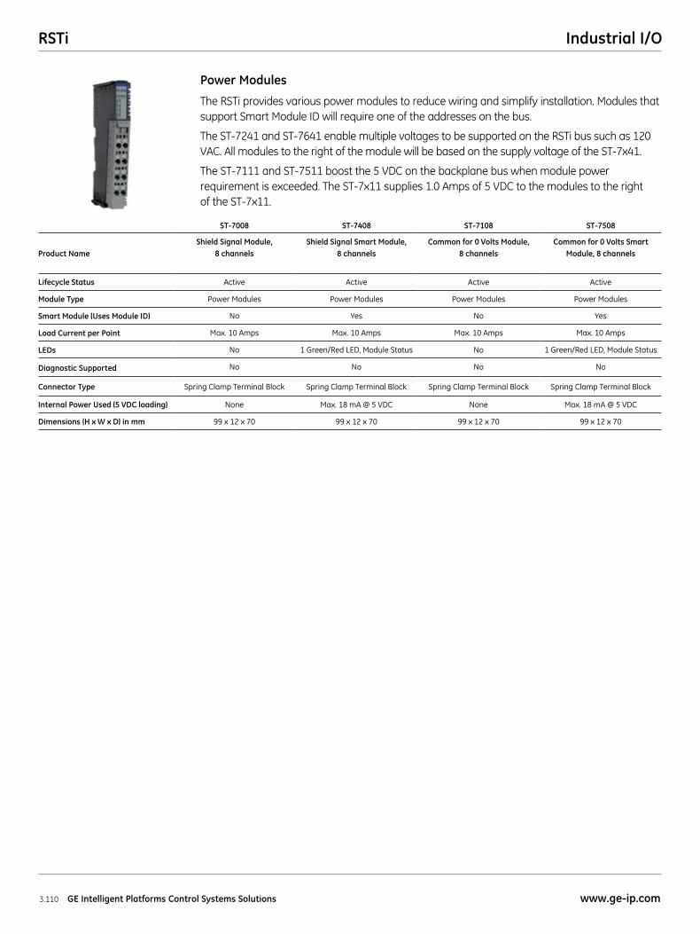
RSTi Industrial I/O
3.110 GE Intelligent Platforms Control Systems Solutions www.ge-ip.com
The RSTi provides various power modules to reduce wiring and simplify installation. Modules that support Smart Module ID will require one of the addresses on the bus.
The ST-7241 and ST-7641 enable multiple voltages to be supported on the RSTi bus such as 120 VAC. All modules to the right of the module will be based on the supply voltage of the ST-7x41.
The ST-7111 and ST-7511 boost the 5 VDC on the backplane bus when module power requirement is exceeded. The ST-7x11 supplies 1.0 Amps of 5 VDC to the modules to the right of the ST-7x11.
Power Modules
ST-7008 ST-7408 ST-7108 ST-7508
Product NameShield Signal Module,
8 channelsShield Signal Smart Module,
8 channelsCommon for 0 Volts Module,
8 channelsCommon for 0 Volts Smart
Module, 8 channels
Lifecycle Status Active Active Active Active
Module Type Power Modules Power Modules Power Modules Power Modules
Smart Module (Uses Module ID) No Yes No Yes
Load Current per Point Max. 10 Amps Max. 10 Amps Max. 10 Amps Max. 10 Amps
LEDs No 1 Green/Red LED, Module Status No 1 Green/Red LED, Module Status
Diagnostic Supported No No No No
Connector Type Spring Clamp Terminal Block Spring Clamp Terminal Block Spring Clamp Terminal Block Spring Clamp Terminal Block
Internal Power Used (5 VDC loading) None Max. 18 mA @ 5 VDC None Max. 18 mA @ 5 VDC
Dimensions (H x W x D) in mm 99 x 12 x 70 99 x 12 x 70 99 x 12 x 70 99 x 12 x 70
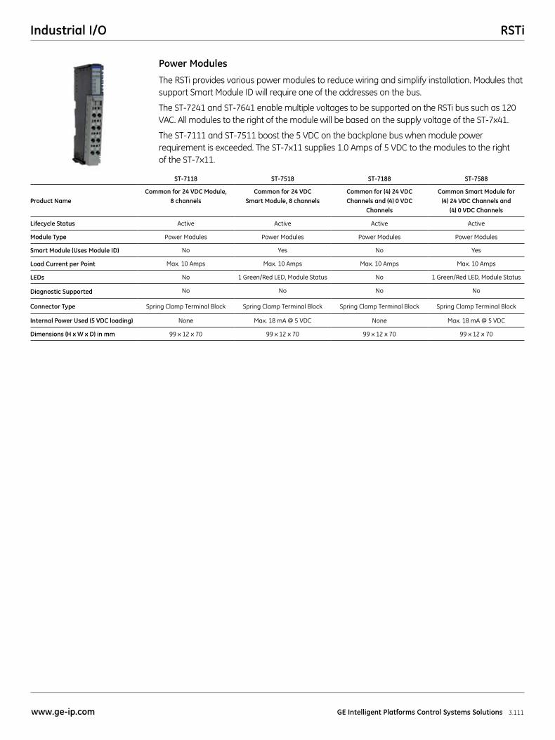
RSTiIndustrial I/O
3.111www.ge-ip.com GE Intelligent Platforms Control Systems Solutions
The RSTi provides various power modules to reduce wiring and simplify installation. Modules that support Smart Module ID will require one of the addresses on the bus.
The ST-7241 and ST-7641 enable multiple voltages to be supported on the RSTi bus such as 120 VAC. All modules to the right of the module will be based on the supply voltage of the ST-7x41.
The ST-7111 and ST-7511 boost the 5 VDC on the backplane bus when module power requirement is exceeded. The ST-7x11 supplies 1.0 Amps of 5 VDC to the modules to the right of the ST-7x11.
Power Modules
ST-7118 ST-7518 ST-7188 ST-7588
Product NameCommon for 24 VDC Module,
8 channelsCommon for 24 VDC
Smart Module, 8 channelsCommon for (4) 24 VDC Channels and (4) 0 VDC
Channels
Common Smart Module for (4) 24 VDC Channels and
(4) 0 VDC Channels
Lifecycle Status Active Active Active Active
Module Type Power Modules Power Modules Power Modules Power Modules
Smart Module (Uses Module ID) No Yes No Yes
Load Current per Point Max. 10 Amps Max. 10 Amps Max. 10 Amps Max. 10 Amps
LEDs No 1 Green/Red LED, Module Status No 1 Green/Red LED, Module Status
Diagnostic Supported No No No No
Connector Type Spring Clamp Terminal Block Spring Clamp Terminal Block Spring Clamp Terminal Block Spring Clamp Terminal Block
Internal Power Used (5 VDC loading) None Max. 18 mA @ 5 VDC None Max. 18 mA @ 5 VDC
Dimensions (H x W x D) in mm 99 x 12 x 70 99 x 12 x 70 99 x 12 x 70 99 x 12 x 70
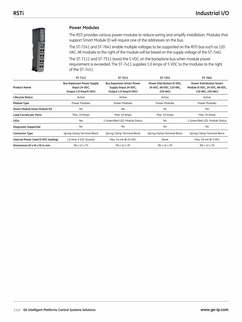
RSTi Industrial I/O
3.112 GE Intelligent Platforms Control Systems Solutions www.ge-ip.com
The RSTi provides various power modules to reduce wiring and simplify installation. Modules that support Smart Module ID will require one of the addresses on the bus.
The ST-7241 and ST-7641 enable multiple voltages to be supported on the RSTi bus such as 120 VAC. All modules to the right of the module will be based on the supply voltage of the ST-7x41.
The ST-7111 and ST-7511 boost the 5 VDC on the backplane bus when module power requirement is exceeded. The ST-7x11 supplies 1.0 Amps of 5 VDC to the modules to the right of the ST-7x11.
Power Modules
ST-7111 ST-7511 ST-7241 ST-7641
Product NameBus Expansion Power Supply
(Input 24 VDC, Output 1.0 Amp/5 VDC)
Bus Expansion Smart Power Supply (Input 24 VDC,
Output 1.0 Amp/5 VDC)
Power Distribution (5 VDC, 24 VDC, 48 VDC, 110 VAC,
220 VAC)
Power Distribution Smart Module (5 VDC, 24 VDC, 48 VDC,
110 VAC, 220 VAC)
Lifecycle Status Active Active Active Active
Module Type Power Modules Power Modules Power Modules Power Modules
Smart Module (Uses Module ID) No Yes No Yes
Load Current per Point Max. 10 Amps Max. 10 Amps Max. 10 Amps Max. 10 Amps
LEDs Yes 1 Green/Red LED, Module Status No 1 Green/Red LED, Module Status
Diagnostic Supported No No No No
Connector Type Spring Clamp Terminal Block Spring Clamp Terminal Block Spring Clamp Terminal Block Spring Clamp Terminal Block
Internal Power Used (5 VDC loading) 1.0 Amp 5 VDC booster Max. 14 mA @ 24 VDC None Max. 18 mA @ 5 VDC
Dimensions (H x W x D) in mm 99 x 12 x 70 99 x 12 x 70 99 x 12 x 70 99 x 12 x 70
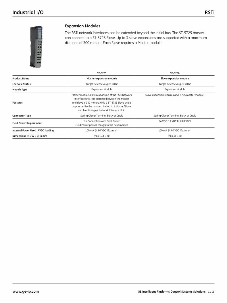
RSTiIndustrial I/O
3.113www.ge-ip.com GE Intelligent Platforms Control Systems Solutions
The RSTi network interfaces can be extended beyond the initial bus. The ST-5725 master can connect to a ST-5726 Slave. Up to 3 slave expansions are supported with a maximum distance of 300 meters. Each Slave requires a Master module.
Expansion Modules
ST-5725 ST-5726
Product Name Master expansion module Slave expansion module
Lifecycle Status Target Release August 2012 Target Release August 2012
Module Type Expansion Module Expansion Module
Features
Master module allows expansion of the RSTi Network Interface unit. The distance between the master
and slave is 300 meters. Only 1 ST-5726 Slave unit is supported by the master. Limited to 3 Master/Slave
combinations per Network Interface Unit.
Slave expansion requires a ST-5725 master module.
Connector Type Spring Clamp Terminal Block or Cable Spring Clamp Terminal Block or Cable
Field Power RequirementNo Connection with Field Power
Field Power passes though to the next module24 VDC (11 VDC to 28.8 VDC)
Internal Power Used (5 VDC loading) 100 mA @ 5.0 VDC Maximum 160 mA @ 5.0 VDC Maximum
Dimensions (H x W x D) in mm 99 x 19.1 x 70 99 x 31 x 70
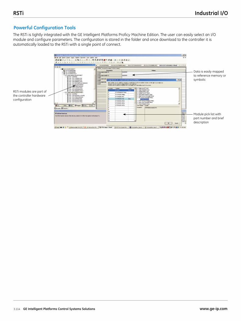
RSTi Industrial I/O
3.114 GE Intelligent Platforms Control Systems Solutions www.ge-ip.com
Powerful Configuration ToolsThe RSTi is tightly integrated with the GE Intelligent Platforms Proficy Machine Edition. The user can easily select an I/O module and configure parameters. The configuration is stored in the folder and once download to the controller it is automatically loaded to the RSTi with a single point of connect.
RSTi modules are part of the controller hardware configuration
Data is easily mapped to reference memory or symbolic
Module pick list with part number and brief description
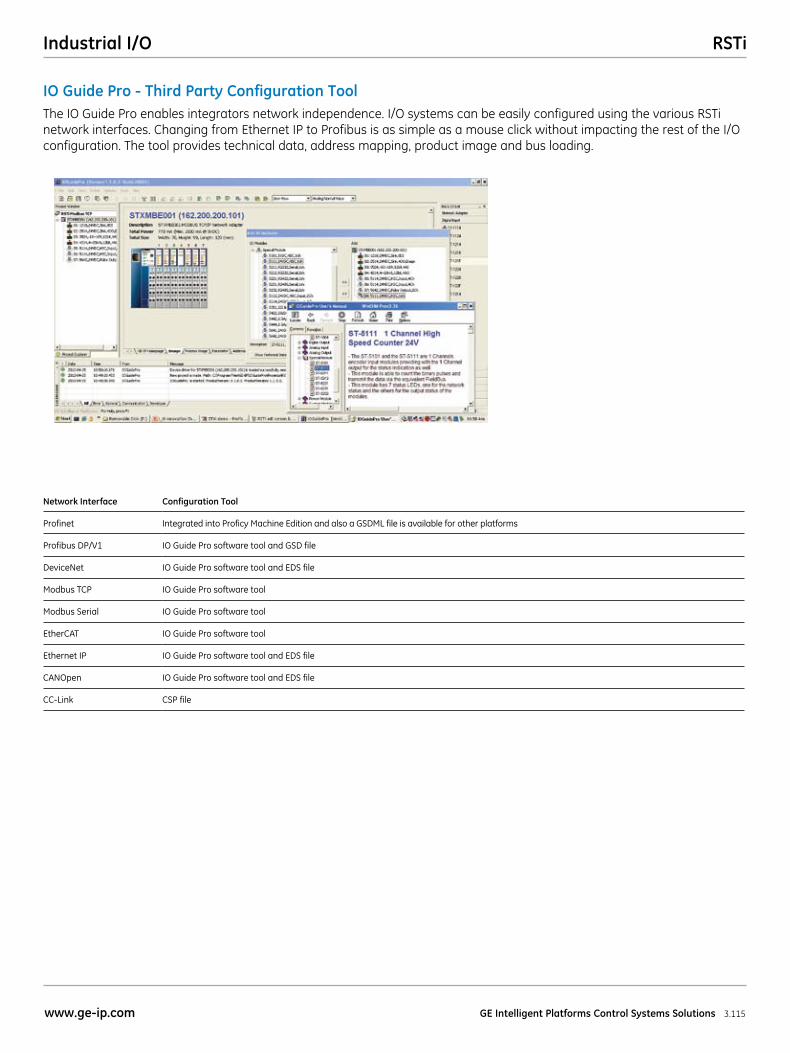
RSTiIndustrial I/O
3.115www.ge-ip.com GE Intelligent Platforms Control Systems Solutions
IO Guide Pro - Third Party Configuration Tool The IO Guide Pro enables integrators network independence. I/O systems can be easily configured using the various RSTi network interfaces. Changing from Ethernet IP to Profibus is as simple as a mouse click without impacting the rest of the I/O configuration. The tool provides technical data, address mapping, product image and bus loading.
Network Interface Configuration Tool
Profinet Integrated into Proficy Machine Edition and also a GSDML file is available for other platforms
Profibus DP/V1 IO Guide Pro software tool and GSD file
DeviceNet IO Guide Pro software tool and EDS file
Modbus TCP IO Guide Pro software tool
Modbus Serial IO Guide Pro software tool
EtherCAT IO Guide Pro software tool
Ethernet IP IO Guide Pro software tool and EDS file
CANOpen IO Guide Pro software tool and EDS file
CC-Link CSP file
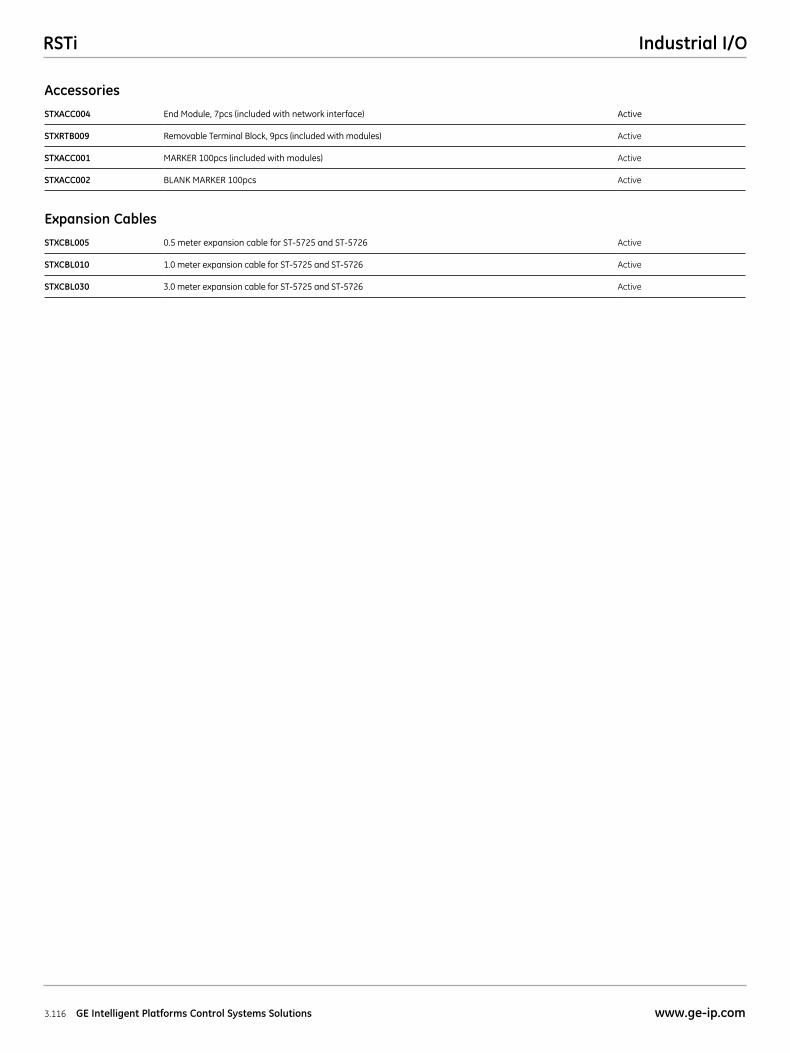
RSTi Industrial I/O
3.116 GE Intelligent Platforms Control Systems Solutions www.ge-ip.com
STXACC004 End Module, 7pcs (included with network interface) Active
STXRTB009 Removable Terminal Block, 9pcs (included with modules) Active
STXACC001 MARKER 100pcs (included with modules) Active
STXACC002 BLANK MARKER 100pcs Active
STXCBL005 0.5 meter expansion cable for ST-5725 and ST-5726 Active
STXCBL010 1.0 meter expansion cable for ST-5725 and ST-5726 Active
STXCBL030 3.0 meter expansion cable for ST-5725 and ST-5726 Active
Accessories
Expansion Cables
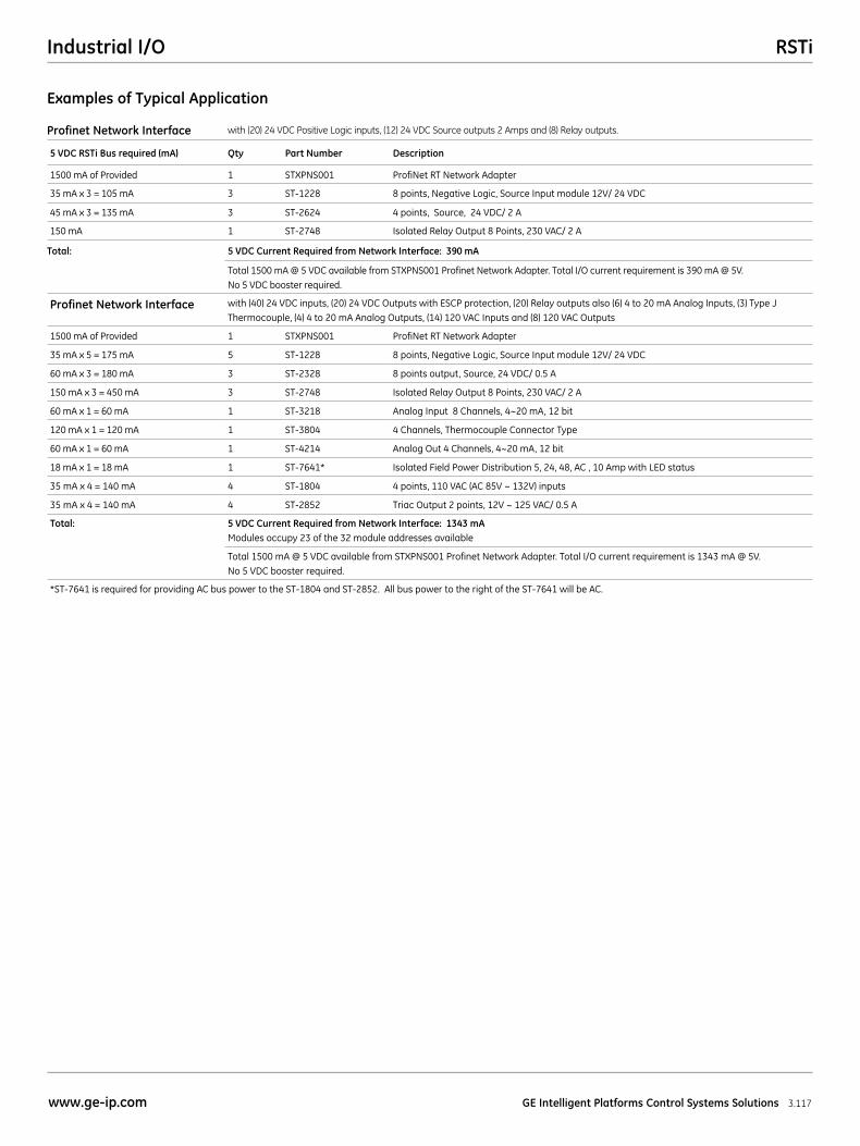
RSTiIndustrial I/O
3.117www.ge-ip.com GE Intelligent Platforms Control Systems Solutions
Profinet Network Interface with (20) 24 VDC Positive Logic inputs, (12) 24 VDC Source outputs 2 Amps and (8) Relay outputs.
5 VDC RSTi Bus required (mA) Qty Part Number Description
1500 mA of Provided 1 STXPNS001 ProfiNet RT Network Adapter
35 mA x 3 = 105 mA 3 ST-1228 8 points, Negative Logic, Source Input module 12V/ 24 VDC
45 mA x 3 = 135 mA 3 ST-2624 4 points, Source, 24 VDC/ 2 A
150 mA 1 ST-2748 Isolated Relay Output 8 Points, 230 VAC/ 2 A
Total: 5 VDC Current Required from Network Interface: 390 mA
Total 1500 mA @ 5 VDC available from STXPNS001 Profinet Network Adapter. Total I/O current requirement is 390 mA @ 5V. No 5 VDC booster required.
Profinet Network Interface with (40) 24 VDC inputs, (20) 24 VDC Outputs with ESCP protection, (20) Relay outputs also (6) 4 to 20 mA Analog Inputs, (3) Type J Thermocouple, (4) 4 to 20 mA Analog Outputs, (14) 120 VAC Inputs and (8) 120 VAC Outputs
1500 mA of Provided 1 STXPNS001 ProfiNet RT Network Adapter
35 mA x 5 = 175 mA 5 ST-1228 8 points, Negative Logic, Source Input module 12V/ 24 VDC
60 mA x 3 = 180 mA 3 ST-2328 8 points output, Source, 24 VDC/ 0.5 A
150 mA x 3 = 450 mA 3 ST-2748 Isolated Relay Output 8 Points, 230 VAC/ 2 A
60 mA x 1 = 60 mA 1 ST-3218 Analog Input 8 Channels, 4~20 mA, 12 bit
120 mA x 1 = 120 mA 1 ST-3804 4 Channels, Thermocouple Connector Type
60 mA x 1 = 60 mA 1 ST-4214 Analog Out 4 Channels, 4~20 mA, 12 bit
18 mA x 1 = 18 mA 1 ST-7641* Isolated Field Power Distribution 5, 24, 48, AC , 10 Amp with LED status
35 mA x 4 = 140 mA 4 ST-1804 4 points, 110 VAC (AC 85V ~ 132V) inputs
35 mA x 4 = 140 mA 4 ST-2852 Triac Output 2 points, 12V ~ 125 VAC/ 0.5 A
Total: 5 VDC Current Required from Network Interface: 1343 mA Modules occupy 23 of the 32 module addresses available
Total 1500 mA @ 5 VDC available from STXPNS001 Profinet Network Adapter. Total I/O current requirement is 1343 mA @ 5V. No 5 VDC booster required.
*ST-7641 is required for providing AC bus power to the ST-1804 and ST-2852. All bus power to the right of the ST-7641 will be AC.
Examples of Typical Application