Embed Size (px)
Citation preview
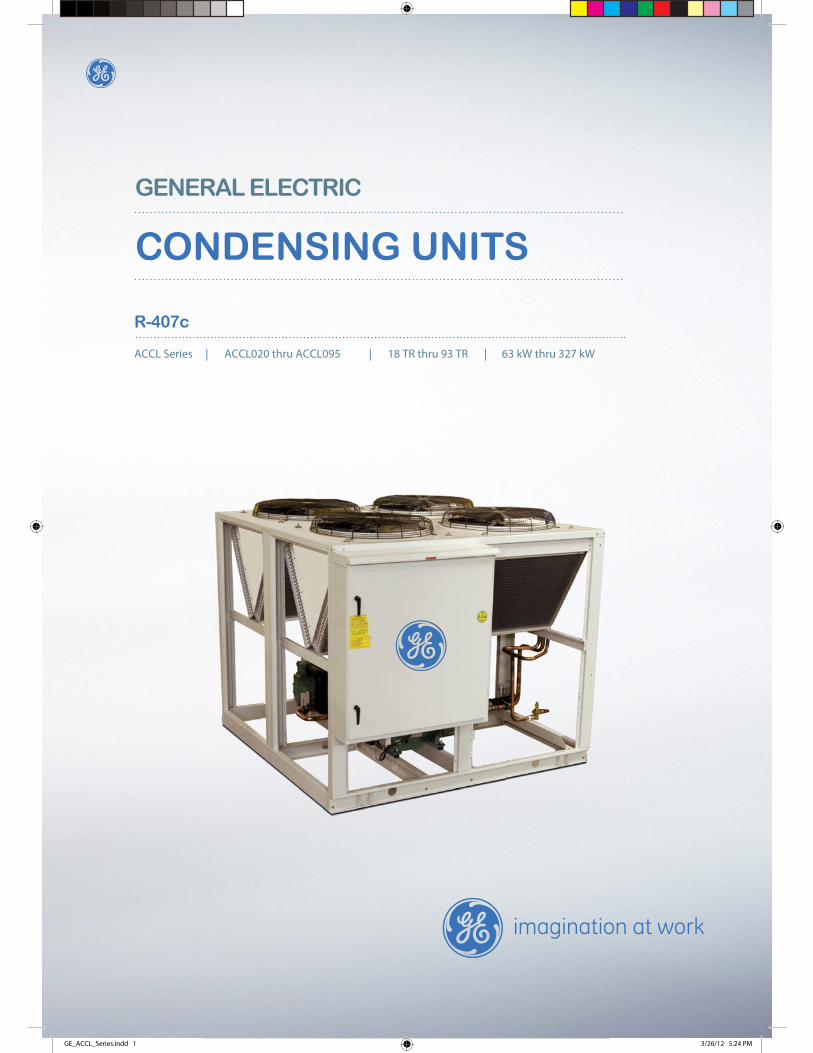
R-407c
ACCL Series | ACCL020 thru ACCL095 | 18 TR thru 93 TR | 63 kW thru 327 kW
GENERAL ELECTRIC
CONDENSING UNITS
GE_ACCL_Series.indd 1 3/26/12 5:24 PM

GE_ACCL_Series.indd 2 3/26/12 5:24 PM
1
Model decoding . . . . . . . . . . . . . . . . . . . . . . . . . . . . . . . . . . . . . . . . . . . . . . . . . . . . . . . . . . . . . . . . . . . . . . . . . . . . 2
Introduction . . . . . . . . . . . . . . . . . . . . . . . . . . . . . . . . . . . . . . . . . . . . . . . . . . . . . . . . . . . . . . . . . . . . . . . . . . . . . 3-5
Standard specifi cations . . . . . . . . . . . . . . . . . . . . . . . . . . . . . . . . . . . . . . . . . . . . . . . . . . . . . . . . . . . . . . . . . . . 6-7
Options & accessories . . . . . . . . . . . . . . . . . . . . . . . . . . . . . . . . . . . . . . . . . . . . . . . . . . . . . . . . . . . . . . . . . . . . 8-9
Physical data . . . . . . . . . . . . . . . . . . . . . . . . . . . . . . . . . . . . . . . . . . . . . . . . . . . . . . . . . . . . . . . . . . . . . . . . . . . . . 10
Selection procedure . . . . . . . . . . . . . . . . . . . . . . . . . . . . . . . . . . . . . . . . . . . . . . . . . . . . . . . . . . . . . . . . . . . . . . . 11
Performance data . . . . . . . . . . . . . . . . . . . . . . . . . . . . . . . . . . . . . . . . . . . . . . . . . . . . . . . . . . . . . . . . . . . . . . . 12-13
Electrical data . . . . . . . . . . . . . . . . . . . . . . . . . . . . . . . . . . . . . . . . . . . . . . . . . . . . . . . . . . . . . . . . . . . . . . . . . . . . 14
Dimensions . . . . . . . . . . . . . . . . . . . . . . . . . . . . . . . . . . . . . . . . . . . . . . . . . . . . . . . . . . . . . . . . . . . . . . . . . . . . 15-16
Typical schematic wiring diagram . . . . . . . . . . . . . . . . . . . . . . . . . . . . . . . . . . . . . . . . . . . . . . . . . . . . . . . . . 17-19
Rigging instructions . . . . . . . . . . . . . . . . . . . . . . . . . . . . . . . . . . . . . . . . . . . . . . . . . . . . . . . . . . . . . . . . . . . . . . 20
Installation clearance . . . . . . . . . . . . . . . . . . . . . . . . . . . . . . . . . . . . . . . . . . . . . . . . . . . . . . . . . . . . . . . . . . . . . . 21
Mounting location . . . . . . . . . . . . . . . . . . . . . . . . . . . . . . . . . . . . . . . . . . . . . . . . . . . . . . . . . . . . . . . . . . . . . . . . . 22
Load distribution . . . . . . . . . . . . . . . . . . . . . . . . . . . . . . . . . . . . . . . . . . . . . . . . . . . . . . . . . . . . . . . . . . . . . . . . . . 23
Installation instructions . . . . . . . . . . . . . . . . . . . . . . . . . . . . . . . . . . . . . . . . . . . . . . . . . . . . . . . . . . . . . . . . . . . 24
Electrical . . . . . . . . . . . . . . . . . . . . . . . . . . . . . . . . . . . . . . . . . . . . . . . . . . . . . . . . . . . . . . . . . . . . . . . . . . . . . . . . . 25
System design . . . . . . . . . . . . . . . . . . . . . . . . . . . . . . . . . . . . . . . . . . . . . . . . . . . . . . . . . . . . . . . . . . . . . . . . . . . . 25
Continuing research results in steady improvements. Therefore, these specifi cations are subject to change without notice
CONTENTS
GE_ACCL_Series.indd 1 3/26/12 5:24 PM
2
MODEL DECODING
GE_ACCL_Series.indd 2 3/26/12 5:24 PM
1, 2
, 3 &
4B
ASI
C5,
6 &
7NO
MIN
AL C
OO
LING
CAPA
CITY
(TO
NS)
9R
EFR
IGER
ATIO
NC
IRC
UIT
TYP
E
8EL
ECTR
ICA
LSU
PPLY
(V-P
h-H
z)
10EL
ECTR
ICA
L K
ITS
OPT
ION
AC
CL
CON
DEN
SIN
GU
NIT
(R-4
07c)
020
025
030
035
040
050
055
065
080
095
S:D
UA
L SC
ROLL
* H
:DU
AL
SEM
I-HER
MET
IC
REC
IPRO
CA
TIN
G **
L:D
UA
L SE
MI-H
ERM
ETIC
RECI
PRO
CATI
NG
WIT
H
UN
LOA
DER
**(L
EAD
C
OM
PRES
SOR)
L:3
80/4
15-3
-50
(
4 W
IRE)
11C
ON
DEN
SER
CO
IL
A :A
LUM
INU
M F
IN
B :
CO
ATE
D A
LUM
INU
M
FIN
C :
CO
PPER
FIN
D :
ALU
MIN
UM
FIN
WIT
HRe
sisT
ec C
OA
TIN
G
E :C
OPP
ER F
IN W
ITH
Resi
sTec
CO
ATI
NG
A:S
TAN
DA
RD O
PTIO
NS +
M:R
EPLA
CEA
BLE
CORE
FIL
TER
DRI
ER
& S
HU
T-O
FF V
ALV
E
P:P
RESS
URE
GA
UG
ES (S
UC
TIO
N &
D
ISC
HA
RGE)
O:P
RESS
URE
GA
UG
ES (S
UC
TIO
N,
DIS
CH
ARG
E &
OIL
) ++
H:H
OT
GA
S BY
PASS
VA
LVE
R:C
ON
DEN
SER
PRES
SURE
REL
IEF
VA
LVE
J: M
& P
CO
MBO
K: M
& O
CO
MBO
N: M
& H
CO
MBO
Q: M
& R
CO
MBO
S: M
, H &
R C
OM
BO
T: M
, H &
P C
OM
BO
U: M
, H &
O C
OM
BO
V: A
, H &
R C
OM
BO
F: A
, H &
P C
OM
BO
G: A
, H &
O C
OM
BO
L: A
, H, P
& R
CO
MBO
B: M
, H, O
& R
CO
MBO13
MEC
HA
NIC
AL
KIT
S O
PTIO
NS
NO
TES:
*–
Dua
l scr
oll c
ompr
esso
rs a
re a
vaila
ble
up to
mod
els
AC
CL0
55 o
nly
.
**–
Dua
l sem
i-her
met
ic c
ompr
esso
rs a
re a
vaila
ble
for m
odel
s A
CC
L065
- A
CC
L095
onl
y.
***
–A
com
bina
tion
of v
olt f
ree
cont
act o
ptio
n: 1
. Uni
t ON
indi
catio
n, 2
. Com
pres
sor R
UN
/TRI
P, 3
. Uni
t trip
indi
catio
n.+
–S
tand
ard
optio
ns (f
or m
odel
s up
to A
CC
L055
onl
y) c
onta
in s
eale
d ty
pe fi
lter d
rier,
fixed
low
& h
igh
pres
sure
sw
itche
s.St
anda
rd o
ptio
ns (f
or m
odel
s A
CC
L065
- A
CC
L095
onl
y) c
onta
in re
plac
eabl
e fil
ter d
rier,
ball
valv
e, s
ight
gla
ss, m
uffler
and
wit
hout
spr
ing
isol
ator
.++
–O
il pr
essu
re g
auge
is a
pplic
able
for s
emi-h
erm
etic
com
pres
sors
onl
y.++
+–
Sou
nd a
tten
uato
r is
appl
icab
le fo
r sem
i-her
met
ic c
ompr
esso
rs o
nly.
A:S
TAN
DA
RD O
PTIO
NS +
K:F
AN
CYC
LIN
G A
ND
AD
JUST
ABL
E H
IGH
&
LOW
PRE
SSU
RESW
ITC
HES
V:V
OLT
FRE
E CO
NTA
CTS **
* C
:CO
MPR
ESSO
R C
IRC
UIT
BREA
KER
P:P
UM
PDO
WN
SO
LEN
OID
VALV
E
B: K
& V
CO
MBO
E: K
& C
CO
MBO
G: K
& P
CO
MBO
T: K
, V &
C C
OM
BO
M: K
, V &
P C
OM
BO
N: V
, C
& P
CO
MBO
L: K
, V,
C &
P C
OM
BO
12 UN
ITEN
CLO
SUR
E
A :S
TAN
DA
RD
G :C
OIL
GU
ARD
F :U
NIT
GU
ARD
C :
COM
PRES
SOR
ENCL
OSU
RE(S
OU
ND
ATTE
NU
A-TO
R) ++
+E
: G &
C C
OM
BO
J: F
& C
CO
MBO
14R
EFR
IGER
AN
TC
HA
RG
ING
(R-4
07c)
H :
HO
LDIN
GCH
ARG
E
F :F
ULL
YCH
ARG
E
3
INTRODUCTION
The ACCL series air cooled condensing units from GE Air Conditioners are designed to provide engineering excellence in comfort air conditioning and industrial cooling with a superior combination of energy saving, performance, application fl ex-ibility, ease of service & maintenance and ability to withstand extreme ambient temperatures. These units can be combined with a wide variety of evaporator coils and blower packages to provide quite and dependable comfort. These units can be installed on a roof tops or at ground level.
The ACCL series are designed to use environmental friendly HFC R-407c refrigerant. HFC R-407c has zero ozone depletion zeotropic blends of HFC refrigerants. It closely matches the properties of R-22 and used in many air conditioning applications.
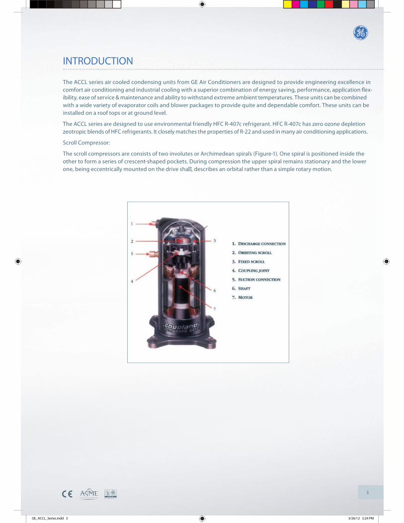
Scroll Compressor:
The scroll compressors are consists of two involutes or Archimedean spirals (Figure-1). One spiral is positioned inside the other to form a series of crescent-shaped pockets. During compression the upper spiral remains stationary and the lower one, being eccentrically mounted on the drive sha� , describes an orbital rather than a simple rotary motion.
GE_ACCL_Series.indd 3 3/26/12 5:24 PM
4
INTRODUCTION
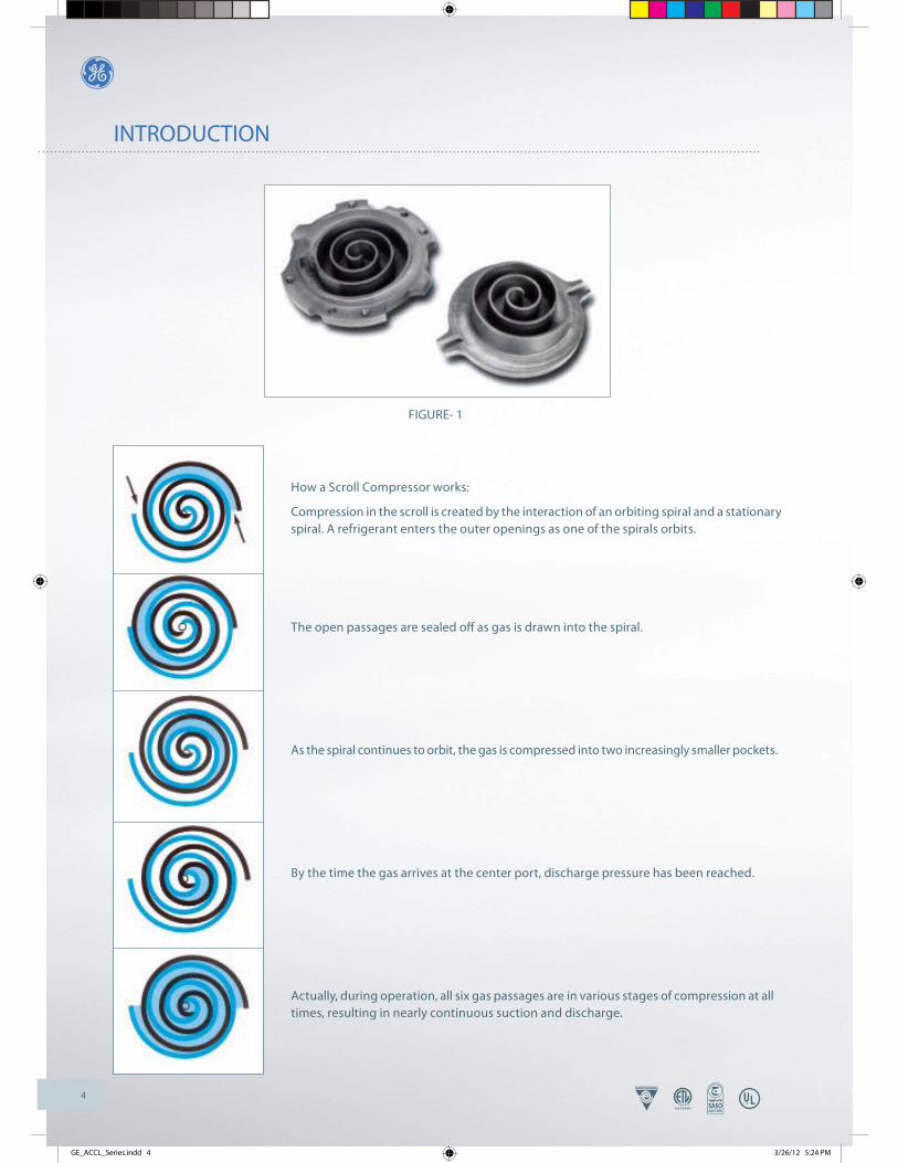
How a Scroll Compressor works:
Compression in the scroll is created by the interaction of an orbiting spiral and a stationary spiral. A refrigerant enters the outer openings as one of the spirals orbits.
The open passages are sealed off as gas is drawn into the spiral.
As the spiral continues to orbit, the gas is compressed into two increasingly smaller pockets.
By the time the gas arrives at the center port, discharge pressure has been reached.
Actually, during operation, all six gas passages are in various stages of compression at all times, resulting in nearly continuous suction and discharge.
FIGURE- 1
GE_ACCL_Series.indd 4 3/26/12 5:24 PM
5
INTRODUCTION
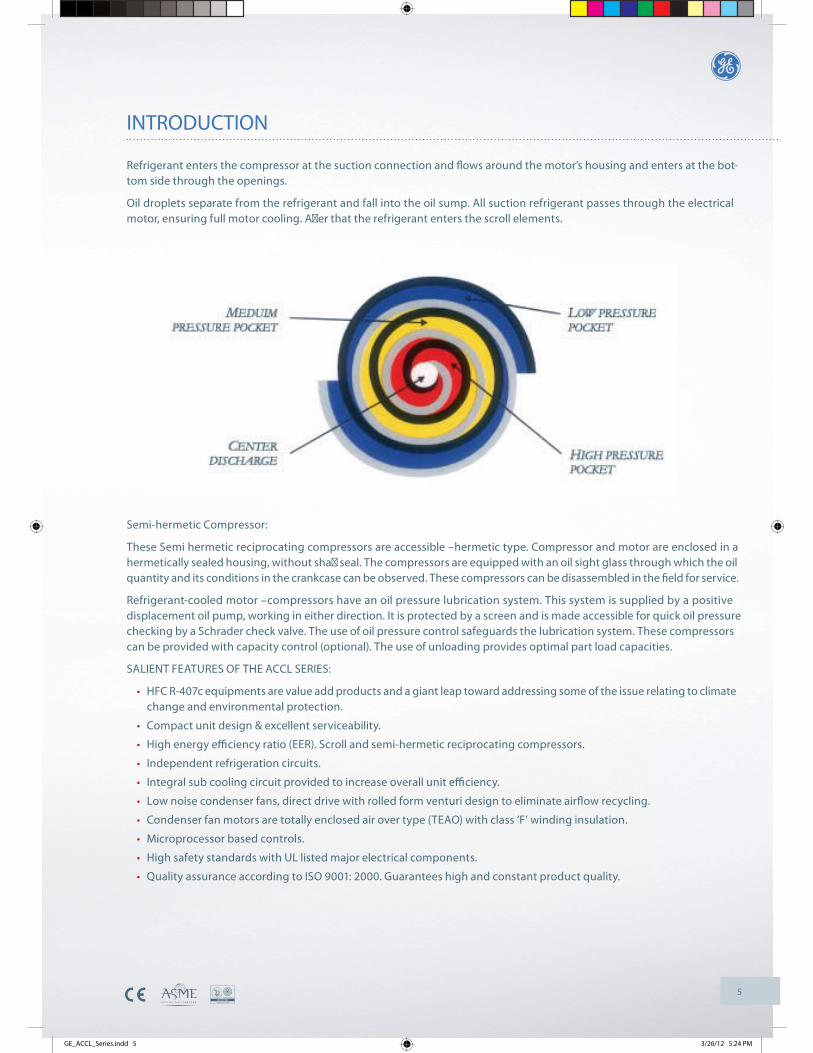
Refrigerant enters the compressor at the suction connection and fl ows around the motor’s housing and enters at the bot-tom side through the openings.
Oil droplets separate from the refrigerant and fall into the oil sump. All suction refrigerant passes through the electrical motor, ensuring full motor cooling. A� er that the refrigerant enters the scroll elements.
Semi-hermetic Compressor:
These Semi hermetic reciprocating compressors are accessible –hermetic type. Compressor and motor are enclosed in a hermetically sealed housing, without sha� seal. The compressors are equipped with an oil sight glass through which the oil quantity and its conditions in the crankcase can be observed. These compressors can be disassembled in the fi eld for service.
Refrigerant-cooled motor –compressors have an oil pressure lubrication system. This system is supplied by a positive displacement oil pump, working in either direction. It is protected by a screen and is made accessible for quick oil pressure checking by a Schrader check valve. The use of oil pressure control safeguards the lubrication system. These compressors can be provided with capacity control (optional). The use of unloading provides optimal part load capacities.
SALIENT FEATURES OF THE ACCL SERIES:
HFC R-407c equipments are value add products and a giant leap toward addressing some of the issue relating to climate change and environmental protection.
Compact unit design & excellent serviceability.
High energy efficiency ratio (EER). Scroll and semi-hermetic reciprocating compressors.
Independent refrigeration circuits.
Integral sub cooling circuit provided to increase overall unit efficiency.
Low noise condenser fans, direct drive with rolled form venturi design to eliminate airflow recycling.
Condenser fan motors are totally enclosed air over type (TEAO) with class ‘F’ winding insulation.
Microprocessor based controls.
High safety standards with UL listed major electrical components.
Quality assurance according to ISO 9001: 2000. Guarantees high and constant product quality.
GE_ACCL_Series.indd 5 3/26/12 5:24 PM
6
STANDARD SPECIFICATIONS
A. UNIT CASING & CONSTRUCTION
Unit casing shall be fabricated of heavy gauge (G-90) galvanized steel. Steel sheet panels are zinc coated and galvanized by the hot dip process of lock forming quality conforming to ASTM A 653 commercial weight G-90 followed by backed on electrostatic polyester dry powder coat.
Condensing unit consists of dual or quadruple refrigeration compressors, condenser coil, propeller fans, control wiring and interconnecting piping completely factory assembled. The whole unit is mounted on pressed steel or ‘C’ channel base rail with liffi ing holes. The unit is provided with an integral weather resistant control panel suitable for remote thermostat control, ready for fi eld connection.
B. COMPRESSOR
Scroll compressors are used as standard for models ACCL020-ACCL055 and semi-hermetic reciprocating compressors are standard for models ACCL065 - ACCL095. All the compressors are conforming to ARI 540 standard. The compressors are equipped with internal motor protection, factory installed crankcase heaters and rubber vibration isolators for quiet and effi cient operation. As an option, semi-hermetic compressor can be fi xed on anti-vibration mounting (spring type) along with suction & discharge line vibration eliminators. Oil pressure control is provided on units with semi-hermetic compressor only. Each compressor has lock-out devices to protect it from short cycling when tripped by safety controls. Each compressor has separate condenser coil with safety controls. Sight glass and fi lter drier are standard for all models.
C. CONDENSER COILS
V & W -confi gurations condenser coils are of the enhanced louvered fi n-and-tube type, constructed of seamless 3/8” dia. & 0.014” (0.35mm) inner grooved copper tubes, mechanically bonded to aluminum fi ns for maximum heat transfer effi ciency. As an option, corrugated copper fi ns or acrylic coated aluminum fi ns or other coated coils may be provided. The fi ns have full self spacing collars which completely cover each tube. The staggered tube design improves the thermal effi ciency. End plates support sheets are heavy gauge galvanized steel with extruded collars for better tube support, formed to provide structural strength. Each coil is pressure tested in the factory at not less than 450 psi air pressure.
D. CONDENSER FANS
Condenser fans are constructed of die cast aluminum blades/hubs with direct driven motors. All fans are statically and dy-namically balanced to operate at minimum noise and vibration. Fan blades are designed with appropriate pitch angle which result in maximum airfl ow through the condenser coil.
E. CONDENSER FAN MOTOR
Condenser fans, the impeller and motors are so constructed to form an integral unit. All fan motors shall be three phase with class ‘F’ winding insulation and ball bearings for high ambient application. These fan motors are of totally enclosed air over type (TEAO) with inherent thermal protection of automatic reset type & specially designed for outdoor applications.
F. SERVICE VALVES
Both suction and liquid service valves are brass, back seating type with sweat connections. Valves are externally located so refrigerant piping connections can be made quickly and easily.
G. CONTROL PANEL
The control panel design is equivalent to NEMA-4 standard with hinged door for easy access ensuring dust and weather- proof construction. Internal power and control wiring is neatly routed, properly anchored and all wires are identifi ed with cable markers as per NEC standard applicable to HVAC units.
The electrical controls used in the control panel are UL approved, which are reliable in operation at high ambient conditions for a long period.
GE_ACCL_Series.indd 6 3/26/12 5:24 PM
7
STANDARD SPECIFICATIONS, OPTIONS & ACCESSORIES
H. MICROPROCESSOR CONTROLLER
These condensing units are provided with a microprocessor control board incorporating the following features:
BALANCE LOADING OF COMPRESSORS : The unit’s electronic control automatically operates lead/lag sequence of compressors. This is to load the compressors evenly over long periods of operation. If required however, compressor 1 can also be set to always lead. In this case, compressor 1 always starts first and stops last. (Selectable through dip switch setting on control board).
PUMP DOWN FUNCTION: In units equipped with pump down system, the controller provides the time delay between solenoid’s opening and compressor starting to equalize the pressure in the system necessary for compressor to startup. (Selectable through dip switch setting on control board).
COMPRESSOR ANTI-RECYCLING PROTECTION: The controller has a built-in 3 minutes minimum off timer for com-pressor. This is for compressor protection in case of accidental manual re-set or immediate re-cycling of thermostat due to load demand.
COMPRESSOR LOCK-OUT FUNCTION: If any of the unit’s safety control trips due to abnormal conditions, the electronic controls locks out the compressor after a pre-determined timing preventing a re-start unless attended by a qualified service technician. The unit can be re-started through thermostat re-set after ensuring safe system conditions.
FAULT DIAGNOSTICS: In case of system fault, LED’s on the board emits a flashing signal indicating where the fault is. This is to guide the service technician in identifying the fault.
DIGITAL I/O’s: The unit’s control board is compatible to operate with a DDC controller or any standard 24V A.C. ther-mostat commercially available.
SEQUENTIAL CONTROL: With input signals from the thermostat, the motors in the equipment is started in sequential order: supply fan – condenser fan – compressor; at a pre-determined timings.
I. COMPRESSOR OVER LOAD PROTECTOR
The compressors has built-in thermal protector for its protection against high winding temperatures. Motor starter control is equipped with an external overload relay as an additional protection against overload.
J. UNDER VOLTAGE MONITOR (UVM)
This device protects the motors in the unit from faults such as; under or over voltage, unbalance & phase reversal of the power supply. When the device sensed such faults, it will cut-off the supply in the control circuit thereby cutting off power to the motors. The voltage monitor will re-set automatically when power is brought back to it’s normal conditions.
K. CRANKCASE HEATERS
Each compressor has crankcase heater. The compressor crankcase heater is always on when the compressor is de- energized. This protects the system against refrigerant migration, oil dilution and potential compressor failure.
L. FILTER DRIER
Refrigerant circuits are kept free of harmful moisture, sludge, acids and oil contaminating particles by the fi lter drier. Cartridge (sealed type) is standard for model ACCL020 - ACCL055 and for all other models replaceable core fi lter drier is provided.
M. SIGHT GLASS
Moisture indicating sight glass (supplied loose) to be installed in liquid line in the fi eld. Easy to read color indicator shows moisture contents and provides a mean for checking the system refrigerant charge.
LINE VOLTAGERANGE UNDER VOLTAGE
TRIP
90%190 - 480 VAC
TRIP & RE-SET VOLTAGE (% OF SET POINT)OVER VOLTAGE PHASE IMBALANCE
RE-SET
93%
TRIP
110%
RE-SET
107%
TRIP
6%
RE-SE T
4.5%
GE_ACCL_Series.indd 7 3/26/12 5:24 PM
8
OPTIONS & ACCESSORIES
A. CAPACITY CONTROL
On semi-hermetic compressors, capacity control is achieved by cycling compressors on /off and cylinder unloading. The use of unloading provides good part load capacities.
B. HOT GAS BYPASS CONTROL
Hot gas bypass is available as an option on the lead circuit to permit operation of the system down to 80% of its unloaded capacity. Under low ambient condition, it controls temperature by eliminating the need to cycle the compressor on and off , ensuring narrow temperature swing and lengthen the life span of the compressor.
C. ADVANCE MICROPROCESSOR
Advance microprocessor control can be off ered to achieve precise control and safety functions of the condensing units. Microprocessor is simple to use, push button keyboard allows to access the operating conditions, control set points and alarm history clearly displayed on a multi-line backed illuminated LCD panel. Also it’s compatible with building manage- ment system and adoptable to LON protocol.
D. FAN CYCLE SWITCH HEAD PRESSURE CONTROL (FCS)
The capacity of air-cooled condensers varies with the diff erence between condensing temperature and condenser entering air temperate (ambient temperature). It increases as this diff erence increases. For a given capacity, a drop in the ambient temperature will lower the condensing temperatures and if the ambient temperature drops below a given limit, head pres-sure control is required.
Control shall be set for a minimum of 95°F (35°C) saturated refrigerant condensing temperature, or to suit the specifi ed application.
E. PUMP DOWN SOLENOID VALVE (PDS)
A pump down solenoid valve may be installed in the liquid line. When the room thermostat is satisfi ed, the valve closes and the compressor continues to run until a substantial portion of the refrigerant has been pumped out from the evaporator. The low-pressure switch will cycle off the compressor at a predetermined evaporator pressure.
F. ADJUSTABLE HIGH PRESSURE SWITCH (HPS)
Field adjustable high pressure switch provides safety protection in the case of excessive discharge pressure. Typical factory pressure settings are shown in table below.
G. ADJUSTABLE LOW PRESSURE SWITCH (LPS)
Field adjustable low pressure switch provides safety protection in the case of low suction pressure and loss of refrigerant charge. Typical factory pressure settings are shown in table below.
H. CIRCUIT BREAKER
Protect against compressor & condenser fans branch circuit fault. When tripped (Manually or automatically), the breaker opens the power supply to the compressor and control circuit through auxiliary contacts.
I. PRESSURE GAUGES
Suction, discharge and oil (semi hermetic compressor only) pressure gauges.
J. DISCHARGE LINE MUFFLERS
Discharge line muffl ers are installed to eliminate noise due to refrigerant pulsation.
ESOLCNEPO
450 ± 10 Psig 360 ± 15 Psig
ESOLCNEPO25 ± 5 Psi g 50 ± 5 Psig
GE_ACCL_Series.indd 8 3/26/12 5:24 PM
9
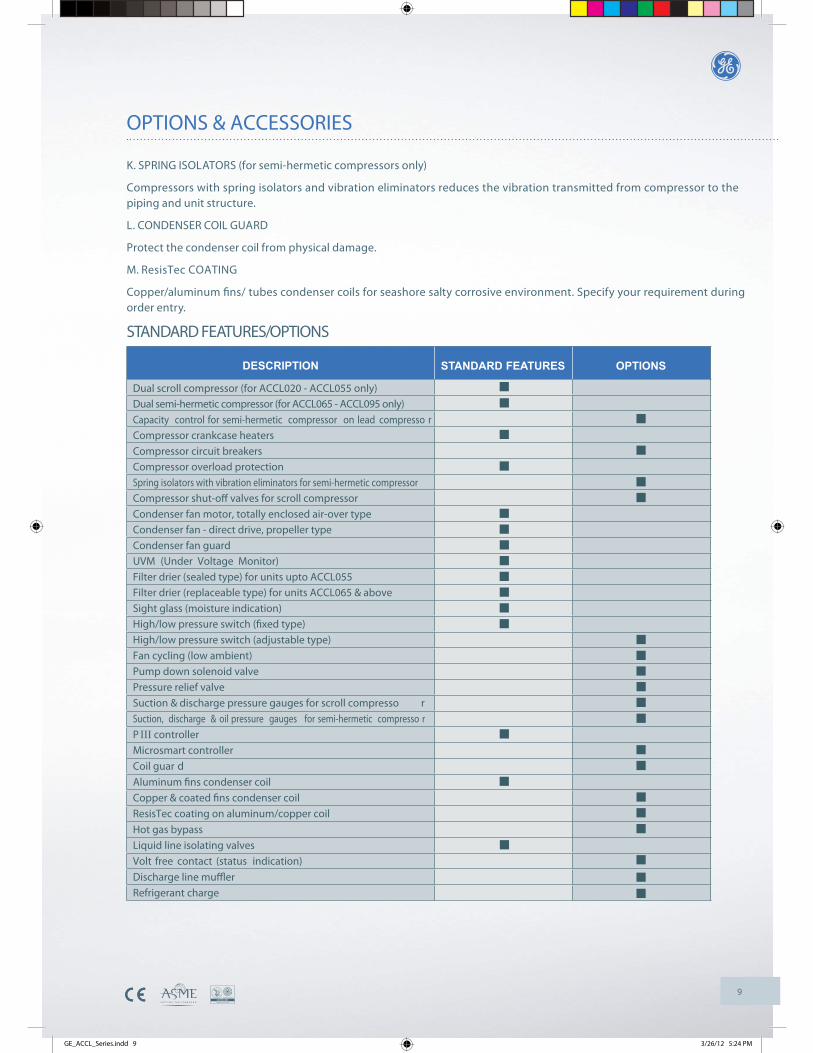
OPTIONS & ACCESSORIES
DESCRIPTION OPTIONS
Dual scroll compressor (for ACCL020 - ACCL055 only)Dual semi-hermetic compressor (for ACCL065 - ACCL095 only)Capacity control for semi-hermetic compressor on lead compresso rCompressor crankcase heatersCompressor circuit breakersCompressor overload protectionSpring isolators with vibration eliminators for semi-hermetic compressorCompressor shut-off valves for scroll compressorCondenser fan motor, totally enclosed air-over typeCondenser fan - direct drive, propeller typeCondenser fan guardUVM (Under Voltage Monitor)Filter drier (sealed type) for units upto ACCL055Filter drier (replaceable type) for units ACCL065 & aboveSight glass (moisture indication)High/low pressure switch (fixed type)High/low pressure switch (adjustable type)Fan cycling (low ambient)Pump down solenoid valvePressure relief valveSuction & discharge pressure gauges for scroll compresso rSuction, discharge & oil pressure gauges for semi-hermetic compresso rP III controllerMicrosmart controllerCoil guar dAluminum fins condenser coilCopper & coated fins condenser coilResisTec coating on aluminum/copper coilHot gas bypassLiquid line isolating valvesVolt free contact (status indication)Discharge line mufflerRefrigerant charge
STANDARD FEATURES
K. SPRING ISOLATORS (for semi-hermetic compressors only)
Compressors with spring isolators and vibration eliminators reduces the vibration transmitted from compressor to the piping and unit structure.
L. CONDENSER COIL GUARD
Protect the condenser coil from physical damage.
M. ResisTec COATING
Copper/aluminum fi ns/ tubes condenser coils for seashore salty corrosive environment. Specify your requirement during order entry.
STANDARD FEATURES/OPTIONS
GE_ACCL_Series.indd 9 3/26/12 5:24 PM
10
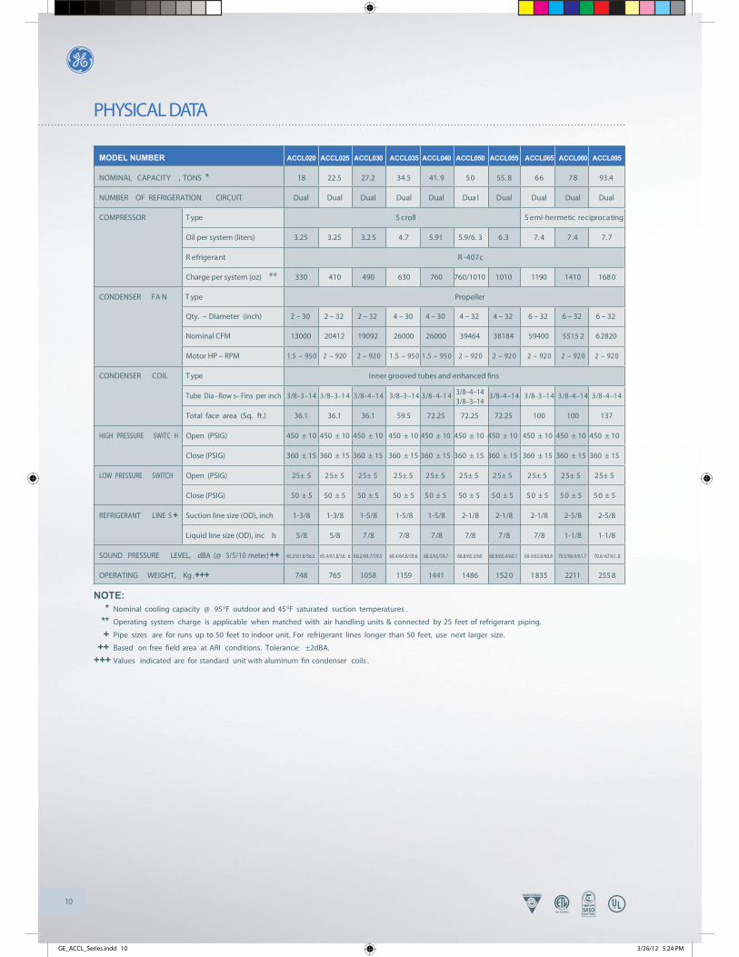
PHYSICAL DATA
NOTE:* Nominal cooling capacity @ 95 0F outdoor and 450F saturated suction temperatures .
** Operating system charge is applicable when matched with air handling units & connected by 25 feet of refrigerant piping.
+ Pipe sizes are for runs up to 50 feet to indoor unit. For refrigerant lines longer than 50 feet, use next larger size.
++ Based on free field area at ARI conditions. Tolerance: ±2dBA.
+++ Values indicated are for standard unit with aluminum fin condenser coils .
590LCC080LCC560LCC550LCC050LCC040LCC530LCC030LCC520LCC020LCCREBMUN LEDOM
NOMINAL CAPACITY , TONS * 18 22.5 27.2 34.5 41. 9 50 55. 8 66 78 93.4
NUMBER OF REFRIGERATION CIRCUIT Dual Dual Dual Dual Dual Dua l Dual Dual Dual Dual
COMPRESSOR epyT gnitacorpicer citemreh-imeS llorcS
Oil per system (liters) 3.25 3.25 3.2 5 4.7 5.91 5.9/6. 3 6.3 7. 4 7.4 7. 7
c704-RtnaregirfeR
Charge per system (oz) ** 330 410 490 630 760 760/1010 1010 1190 1410 168 0
CONDENSER FA N T ype Propeller
Qty. – Diameter (inch) 2 – 30 2 – 32 2 – 32 4 – 30 4 – 30 4 – 32 4 – 32 6 – 32 6 – 32 6 – 32
Nominal CFM 13000 20412 19092 26000 26000 39464 38184 59400 5515 2 62820
Motor HP – RPM 1.5 – 950 2 – 920 2 – 920 1.5 – 950 1.5 – 950 2 – 920 2 – 920 2 – 920 2 – 920 2 – 920
CONDENSER COIL IepyT nner grooved tubes and enhanced fins
Tube Dia –Row s– Fins per inch 3/8–3–14 3/8–3–1 4 3/8–4–14 3/8–3–14 3/8–4–1 4 3/8–4–14 3/8–3–14 3/8–4–14 3/8–4–14
Total face area (Sq. ft.) 36.1 36.1 36.1 59.5 72.25 72.25 72.25 100 100 137
HIGH PRESSURE SWITC H Open (PSIG) 450 ± 10 450 ± 10 450 ± 10 450 ± 10 450 ± 10 450 ± 10 450 ± 10 450 ± 10 450 ± 10 450 ± 10
Close (PSIG) 360 ± 15 360 ± 15 360 ± 15 360 ± 15 360 ± 15 360 ± 15 360 ± 15 360 ± 15 360 ± 15 360 ± 15
LOW PRESSURE SWITCH Open (PSIG) 25± 5 25± 5 25± 5 25± 5 25± 5 25± 5 25± 5 25± 5 25± 5 25± 5
Close (PSIG) 50 ± 5 50 ± 5 50 ± 5 50 ± 5 50 ± 5 50 ± 5 50 ± 5 50 ± 5 50 ± 5 50 ± 5
REFRIGERANT LINE S + Suction line size (OD), inch 1-3/8 1-3/8 1-5/8 1-5/8 1-5/8 2-1/8 2-1/8 2-1/8 2-5/8 2-5/8
Liquid line size (OD), inc h 5/8 5/8 7/8 7/8 7/8 7/8 7/8 7/8 1-1/8 1-1/8
SOUND PRESSURE LEVEL, dBA (@ 3/5/10 meter)++ 65.3/61.8/56.5 65.4/61.8/56. 6 68.2/64.7/59.5 68.4/64.8/59.6 68.5/65/59.7 68.8/65.3/60 68.9/65.4/60.1 69.4/65.8/60.8 70.5/66.9/61.7 70.6/ 67/61. 8
OPERATING WEIGHT, Kg .+++ 748 765 1058 1159 1441 1486 152 0 1835 2211 255 8
3/8–4–143/8–3–14
A A A A AAAAAA
GE_ACCL_Series.indd 10 3/26/12 5:24 PM
11
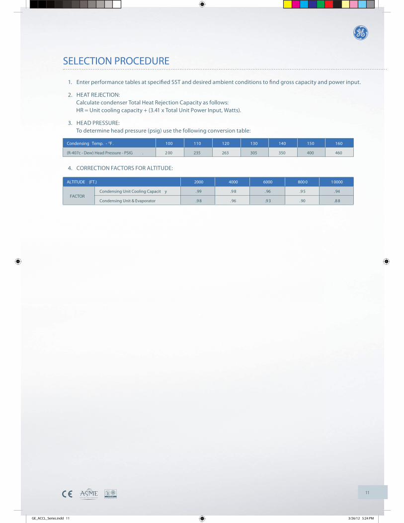
SELECTION PROCEDURE
1. Enter performance tables at specified SST and desired ambient conditions to find gross capacity and power input.
2. HEAT REJECTION: Calculate condenser Total Heat Rejection Capacity as follows: HR = Unit cooling capacity + (3.41 x Total Unit Power Input, Watts).
3. HEAD PRESSURE: To determine head pressure (psig) use the following conversion table:
4. CORRECTION FACTORS FOR ALTITUDE:
ALTITUDE (FT.) 2000 4000 6000 800 0 10000
Condensing Unit Cooling Capacit y .99 .9 8 . 96 .9 5 . 94
Condensing Unit & Evaporator .9 8 . 96 .9 3 . 90 .8 8FACTOR
Condensing Temp. - 0 061051041031021011001.F
(R-407c - Dew) Head Pressure - PSIG . 2 00 235 263 305 350 400 460
GE_ACCL_Series.indd 11 3/26/12 5:24 PM
12
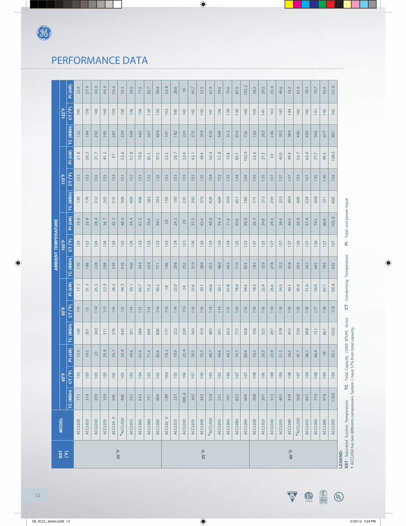
PERFORMANCE DATAA
CC
L020
171
105
15.9
160
114
17.7
150
124
19.6
139
133
21.
81
3214
023
.4
AC
CL0
2521
41
0319
.520
112
21.5
188
122
23.8
174
132
26.
21
6413
82
7.9
AC
CL0
3025
91
0523
243
114
25.5
228
124
28.4
212
133
31.7
202
140
34.
3
AC
CL0
3533
01
0529
.831
111
53
2.9
288
124
36.7
263
133
41.2
243
140
44.
9
AC
CL0
40
395
105
34.7
376
114
38.2
349
124
42.3
315
133
47
287
139
50.
6
*AC
CL0
5046
610
339
.84
4311
344
.34
1012
248
.63
6813
15
2.6
334
138
55.3
AC
CL0
5553
11
0544
.650
111
450
.14
6012
454
.44
0913
25
7.8
368
138
59.6
AC
CL0
6563
31
0461
.658
811
364
.754
31
2267
.54
9613
17
0.0
462
138
71.5
AC
CL0
8075
11
0571
.469
511
475
.263
91
2378
.458
51
3281
.154
71
3982
.7
AC
CL0
9590
41
0585
.683
811
490
.277
11
2394
.170
31
3297
.565
41
3999
.4
AC
CL0
20
189
106
16.
21
7711
61
81
6612
52
01
5513
52
2.2
147
142
23.
8
AC
CL0
2523
71
0519
.922
211
422
.020
81
2424
.21
9313
32
6.7
182
140
28.6
AC
CL0
3028
6..4
106
23.4
269
116
26
252
125
29
235
135
32.
422
414
235
AC
CL0
3536
51
0730
.534
311
633
.631
91
2637
.52
9213
54
2.1
272
142
45.7
AC
CL0
4043
51
0635
.541
011
639
.138
91
2643
.437
01
3548
.435
91
4252
.5
*AC
CL0
5051
61
0540
.748
511
444
.645
51
2449
.84
2813
45
6.4
410
141
61.9
AC
CL0
5553
11
0544
.650
111
450
.146
01
2454
.44
0913
25
7.8
368
138
59.6
AC
CL0
6570
11
0664
.265
311
567
.860
31
2471
.055
01
3373
.851
21
3975
.6
AC
CL0
8083
21
0774
.777
111
678
.971
01
2582
.665
11
3485
.761
01
4087
.5
AC
CL0
9599
91
0789
.492
811
694
.585
51
2599
.07
8013
410
2.9
726
140
105
.2
AC
CL0
2020
81
0816
.519
611
818
.318
31
2720
.31
7113
62
2.6
163
143
24.3
AC
CL0
2526
11
0620
.322
511
622
.422
91
2524
.821
31
3527
.320
21
4129
.2
AC
CL0
3031
51
0823
.929
711
826
.627
81
2729
.62
5913
73
32
4614
33
5.6
AC
CL0
3540
11
0931
.237
811
834
.535
21
2738
.432
31
3743
.030
21
4346
.6
AC
CL0
4047
81
0836
.545
211
840
.142
81
2744
.440
41
3749
.438
91
4453
.3
*AC
CL0
5056
81
0741
.753
611
645
.950
31
2650
.94
6913
55
6.7
446
142
61.4
AC
CL0
5564
71
0946
.760
811
851
.656
71
2757
.65
2413
76
4.6
493
143
70.1
AC
CL0
6577
41
0866
.972
111
770
.966
51
2674
.560
81
3577
.756
61
4179
.7
AC
CL0
8091
81
0978
851
118
82.7
785
127
86.8
721
136
90.3
677
142
92.4
AC
CL0
9511
00
109
93.1
1022
118
98.
89
4212
710
3.8
860
136
108
.380
114
211
1.0
350 F
SST
(0 F)M
OD
EL A
MB
IEN
T TE
MPE
RAT
UR
E
TC (M
BH
)
300 F
CT
(0 F)PI
(kW
)
400 F
850 F
TC (M
BH
)C
T (0 F)
PI (k
W)
950 F
TC (M
BH
)C
T (0 F)
PI (k
W)
1050 F
TC (M
BH
)C
T (0 F)
PI (k
W)
1150 F
TC (M
BH
)12
20 F
LEG
END
:SS
T-
Satu
rate
d Su
ctio
n Te
mpe
ratu
re
TC -
Tota
l C
apac
ity (
1000
BTU
H)
Gro
ss
C
T -
Con
dens
ing
Tem
pera
ture
PI
- To
tal
unit
pow
er in
put
*AC
CL0
50 h
as tw
o di
ffer
ent c
ompr
esso
rs. S
yste
m 1
hav
e 57
% fr
om to
tal c
apac
ity.
CT
(0 F)PI
(kW
)
GE_ACCL_Series.indd 12 3/26/12 5:24 PM
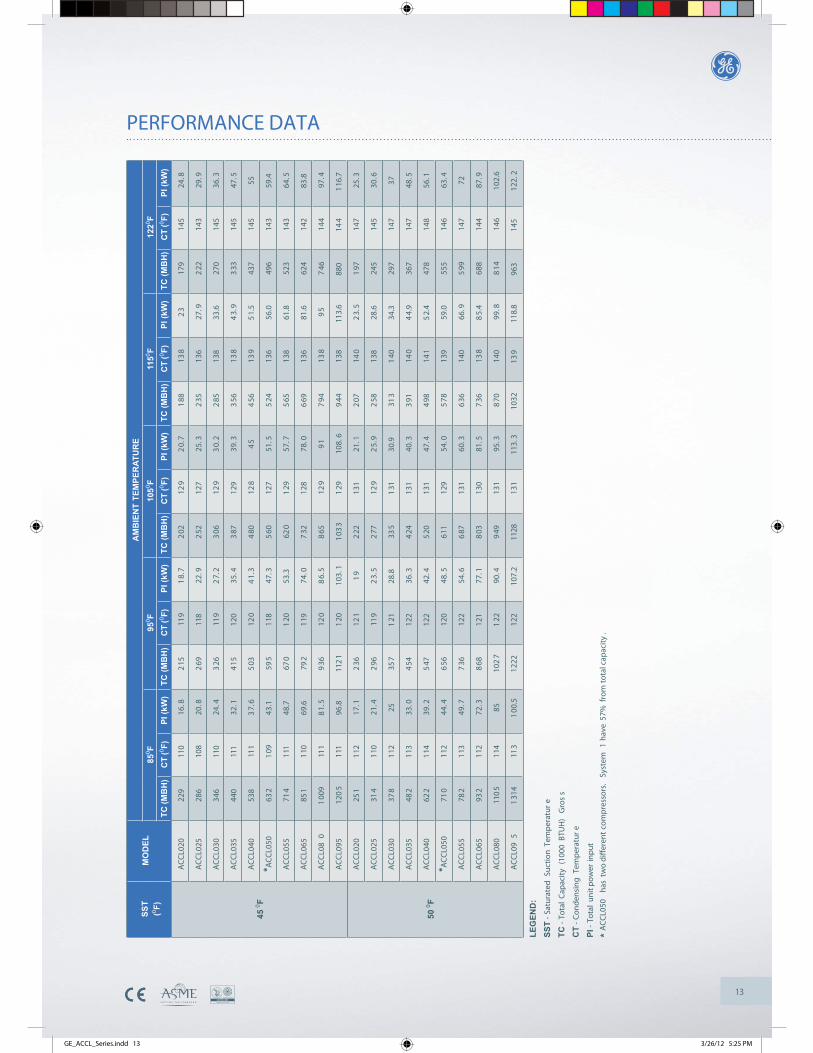
13
PERFORMANCE DATA
AC
CL0
2022
911
016
.82
1511
91
8.7
202
129
20.
71
8813
82
317
914
524
.8
AC
CL0
2528
610
820
.82
6911
822
.92
5212
725
.32
3513
627
.92
2214
329
.9
AC
CL0
3034
611
024
.43
2611
92
7.2
306
129
30.
22
8513
833
.627
014
536
.3
AC
CL0
3544
011
132
.14
1512
035
.43
8712
939
.33
5613
84
3.9
333
145
47.5
AC
CL0
4053
811
13
7.6
503
120
41.
34
8012
84
54
5613
95
1.5
437
145
55
*AC
CL0
5063
21
0943
.159
511
847
.35
6012
751
.55
2413
656
.049
614
359
.4
AC
CL0
5571
411
148
.767
01
2053
.362
01
2957
.75
6513
861
.852
314
364
.5
AC
CL0
6585
111
069
.679
211
974
.07
3212
878
.06
6913
681
.662
414
283
.8
AC
CL0
80
100
911
18
1.5
936
120
86.
58
6512
99
17
9413
89
57
4614
497
.4
AC
CL0
9512
05
111
96.8
112
11
2010
3.1
103
31
2910
8.6
944
138
113.
688
014
41
16.7
AC
CL0
2025
111
217
.12
3612
11
92
2213
121
.12
0714
02
3.5
197
147
25.3
AC
CL0
2531
411
021
.42
9611
92
3.5
277
129
25.
92
5813
828
.624
514
530
.6
AC
CL0
3037
811
225
357
121
28.8
335
131
30.9
313
140
34.3
297
147
37
AC
CL0
3548
211
333
.04
5412
236
.34
2413
140
.33
9114
04
4.9
367
147
48.5
AC
CL0
4062
211
439
.25
4712
242
.45
2013
147
.44
9814
15
2.4
478
148
56.1
*AC
CL0
5071
011
244
.46
5612
048
.561
112
954
.05
7813
959
.055
514
663
.4
AC
CL0
5578
211
349
.77
3612
254
.66
8713
160
.36
3614
066
.95
9914
772
AC
CL0
6593
211
272
.38
6812
177
.18
0313
081
.57
3613
88
5.4
688
144
87.9
AC
CL0
8011
05
114
8510
27
122
90.4
949
131
95.3
870
140
99.8
814
146
102.
6
AC
CL0
95
131
411
31
00.5
1222
122
107.
211
2813
111
3.3
1032
139
118.
896
314
512
2.2
500 F
SST
(0 F)M
OD
EL A
MB
IEN
T TE
MPE
RAT
UR
E
TC (M
BH
)
450 F
CT
(0 F)PI
(kW
)85
0 FTC
(MB
H)
CT
(0 F)PI
(kW
)95
0 FTC
(MB
H)
CT
(0 F)PI
(kW
)10
50 FTC
(MB
H)
CT
(0 F)PI
(kW
)11
50 F
LEG
END
:SS
T- S
atur
ated
Suc
tion
Tem
pera
tur
e
TC-
Tota
l C
apac
ity (
1000
BTU
H)
Gro
ss
CT
- Con
dens
ing
Tem
pera
tur
e
PI-
Tota
l un
it po
wer
inpu
t
*AC
CL0
50
has
two
diff
eren
t co
mpr
esso
rs.
Syst
em 1
hav
e 57
% f
rom
tot
al c
apac
ity.
TC (M
BH
)12
20 FC
T (0 F)
PI (k
W)
GE_ACCL_Series.indd 13 3/26/12 5:25 PM
14
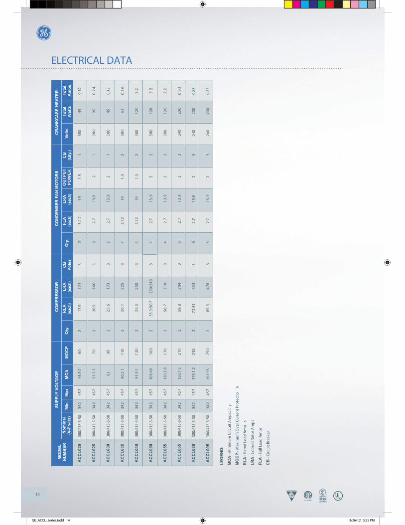
ELECTRICAL DATA
AC
CL0
20
AC
CL0
25
AC
CL0
30
AC
CL0
35
AC
CL0
40
AC
CL0
50
AC
CL0
55
AC
CL0
65
AC
CL0
80
AC
CL0
95
CR
AN
KC
ASE
HEA
TER
Volts
CB
(Qty
.)O
UTP
UT
POW
ERLR
A(e
ach)
FLA
(eac
h)Q
ty.
CB
Pole
sLR
A(e
ach)
RLA
(eac
h)
380/
415-
3-50
380/
415-
3-50
380/
415-
3-50
380/
415-
3-50
380/
415-
3-50
380/
415-
3-50
380/
415-
3-50
380/
415-
3-50
380/
415-
3-50
380/
415-
3-50
MO
DEL
NU
MB
ER
SR
OTO
M N
AF RES
NED
NO
CR
OSSERP
MO
CE
GATL
OV YLPPUS
MO
CP
MC
AM
ax.
Min
.N
omin
al(V
-Ph-
Hz)
342
342
342
342
342
342
342
342
342
342
457
457
457
457
457
457
457
457
457
457
Qty
.
46.5
26
02
17.9
125
32
3.1
21
91
.51
380
450.
12
51.5
37
02
20.5
140
32
2.7
13.9
21
380
90
0.2
4
6390
22
5.6
173
32
2.7
13.9
21
380
450.
12
80.2
111
02
30.
12
253
43.
1219
1.5
238
06
10
.16
91.9
11
202
35.
32
503
43.
1219
1.5
238
012
03
.2
109.
4816
02
35.3
/50.
725
0/31
03
42.
713
.92
23
8012
03.
2
130.
28
170
250
.73
103
42.
71
3.9
22
380
120
3.2
150.
75
210
259
.83
043
62.
71
3.9
23
240
200
0.8
3
179.
12
250
27
2.41
393
36
2.7
13.9
23
240
200
0.83
191.
9329
02
85.3
476
36
2.7
13.9
23
240
200
0.83
LEG
END
:
MC
A - M
inim
um C
ircui
t Am
paci
ty
MO
CP
- Max
imum
Ove
r Cur
rent
Pro
tect
ion
RLA
- Ra
ted
Load
Am
ps
LRA
- Lo
cked
Rot
or A
mps
FLA
- Fu
ll Lo
ad A
mps
CB
- C
ircui
t Bre
aker
Tota
lW
atts
Tota
lA
mps
GE_ACCL_Series.indd 14 3/26/12 5:25 PM
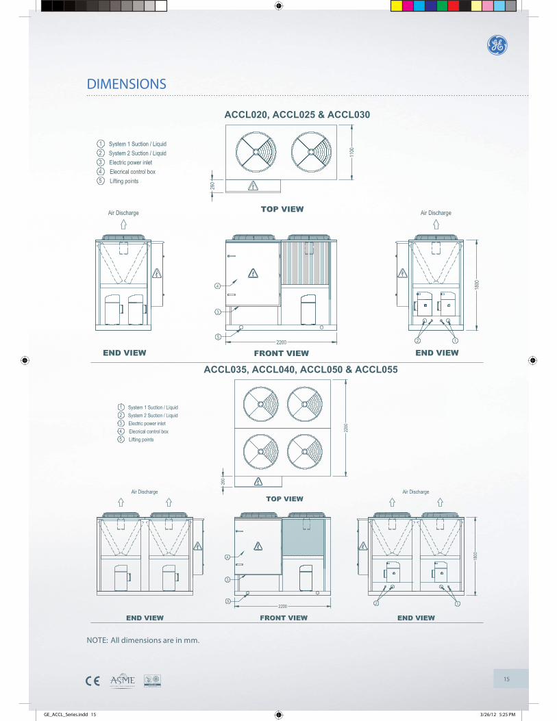
15
DIMENSIONS
NOTE: All dimensions are in mm.
ACCL020, ACCL025 & ACCL030
ACCL035, ACCL040, ACCL050 & ACCL055
GE_ACCL_Series.indd 15 3/26/12 5:25 PM
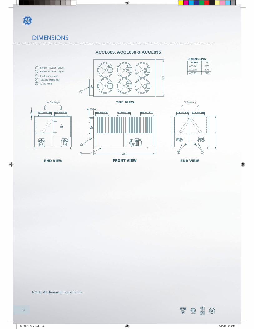
16
DIMENSIONS
NOTE: All dimensions are in mm.
ACCL065, ACCL080 & ACCL095
MODEL HACCL065 2075
ACCL080 2075
ACCL095 2405
DIMENSIONS
GE_ACCL_Series.indd 16 3/26/12 5:25 PM
17
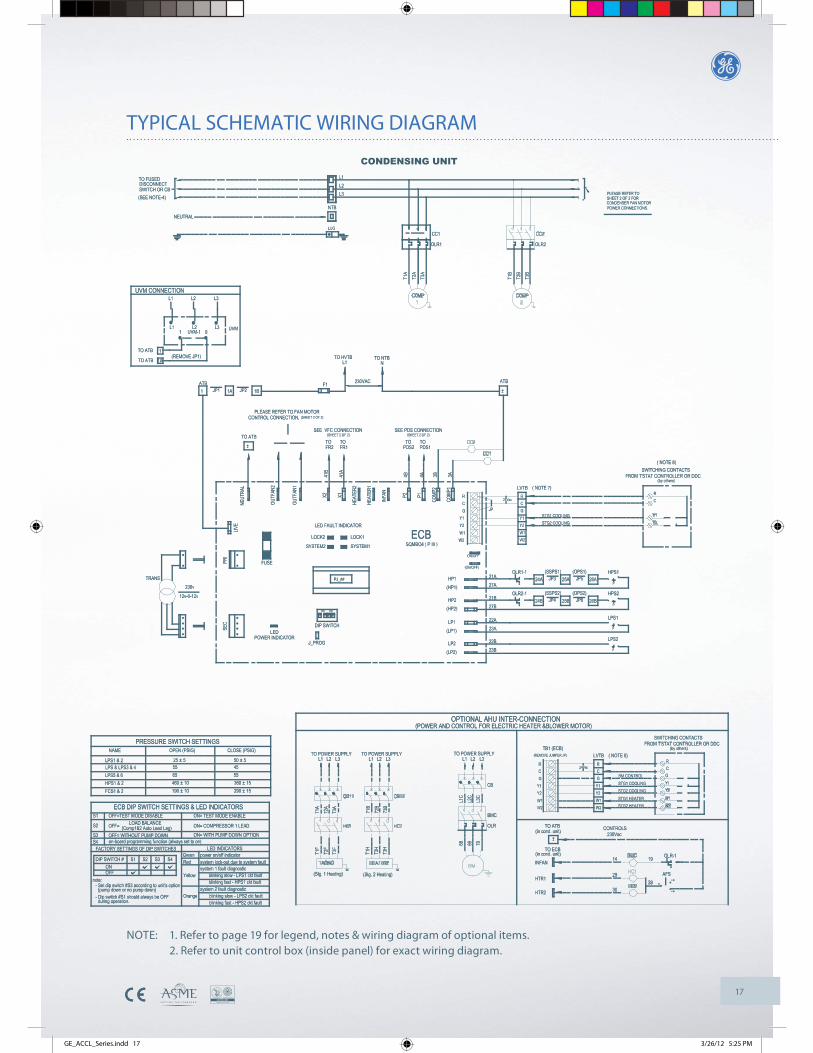
TYPICAL SCHEMATIC WIRING DIAGRAM
CONDENSING UNIT
NOTE: 1. Refer to page 19 for legend, notes & wiring diagram of optional items. 2. Refer to unit control box (inside panel) for exact wiring diagram.
GE_ACCL_Series.indd 17 3/26/12 5:25 PM
18
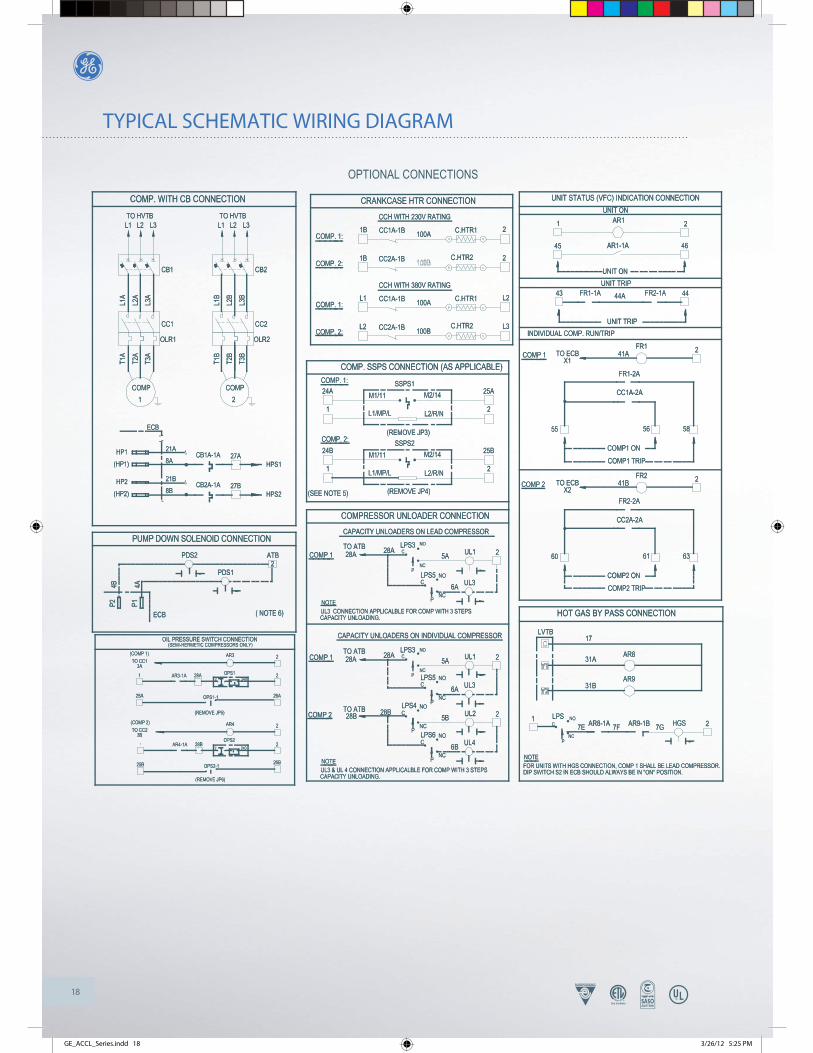
TYPICAL SCHEMATIC WIRING DIAGRAM
OPTIONAL CONNECTIONS
GE_ACCL_Series.indd 18 3/26/12 5:25 PM
19
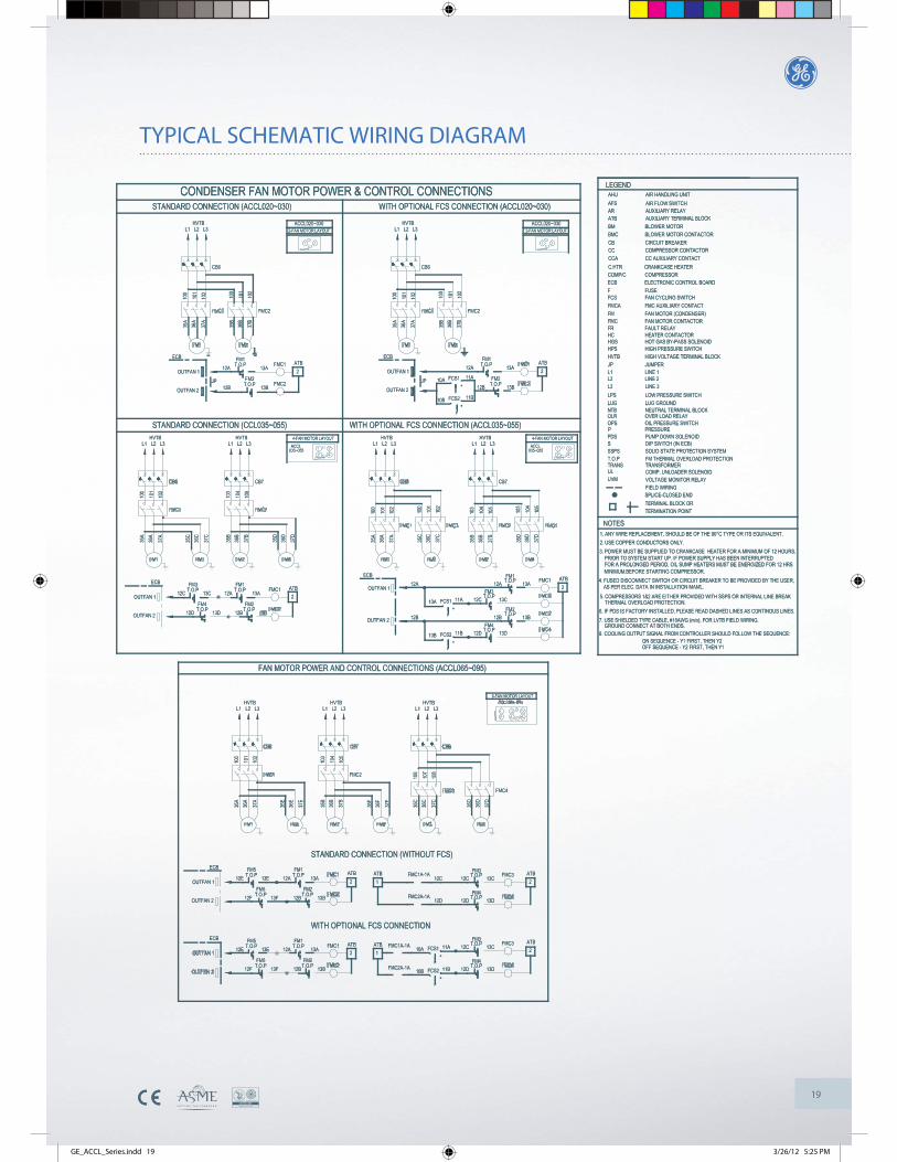
TYPICAL SCHEMATIC WIRING DIAGRAM
GE_ACCL_Series.indd 19 3/26/12 5:25 PM
20
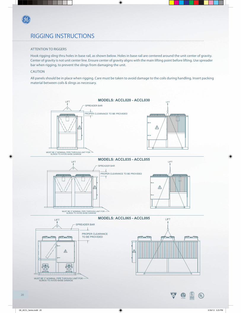
RIGGING INSTRUCTIONS
ATTENTION TO RIGGERS
Hook rigging sling thru holes in base rail, as shown below. Holes in base rail are centered around the unit center of gravity. Center of gravity is not unit center line. Ensure center of gravity aligns with the main lifting point before lifting. Use spreader bar when rigging, to prevent the slings from damaging the unit.
CAUTION
All panels should be in place when rigging. Care must be taken to avoid damage to the coils during handling. Insert packing material between coils & slings as necessary.
LIFT
SPREADER BAR
LIFT
PROPER CLEARANCE TO BE PROVIDED
MUST BE 3" NOMINAL PIPE THROUGH UNIT FOR
SPREADER BAR
PROPER CLEARANCETO BE PROVIDED
MODELS: ACCL020 - ACCL030
MODELS: ACCL035 - ACCL055
MODELS: ACCL065 - ACCL095
GE_ACCL_Series.indd 20 3/26/12 5:25 PM
21
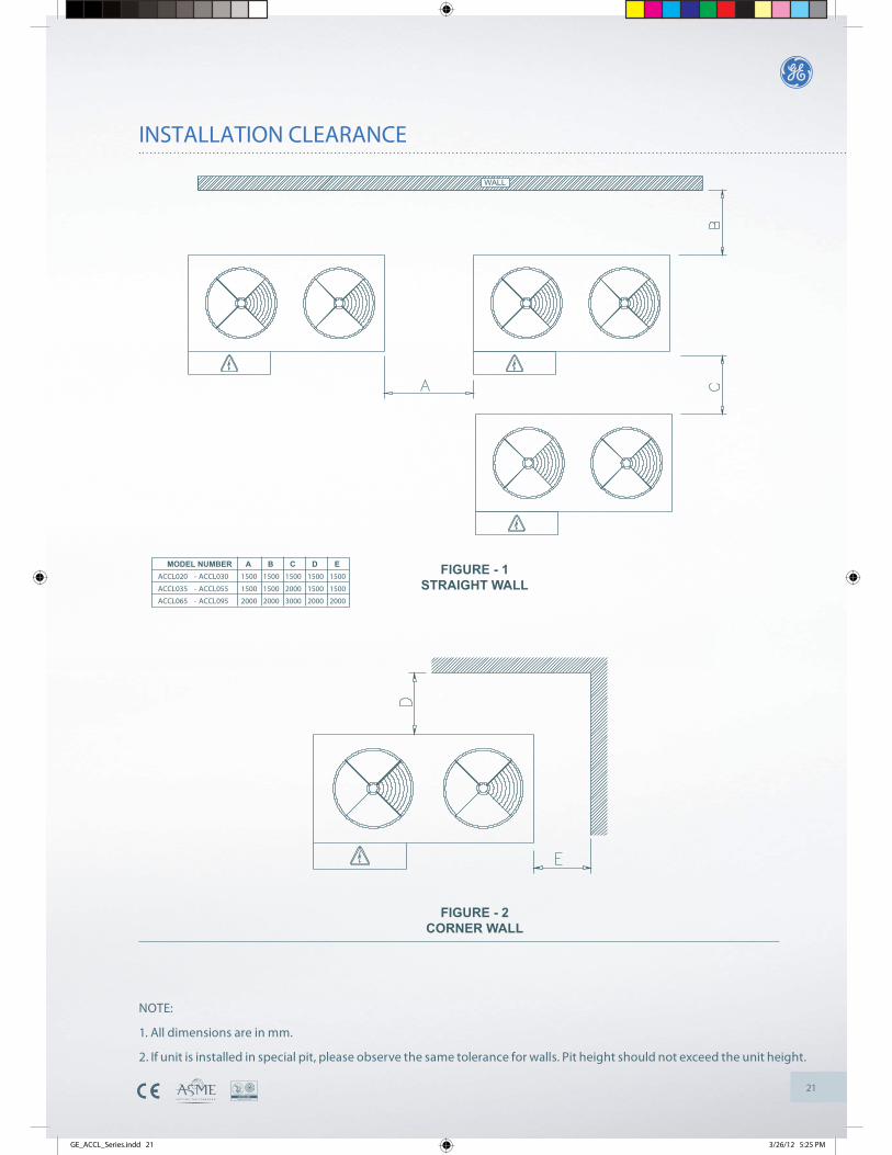
INSTALLATION CLEARANCE
WALL
FIGURE - 2CORNER WALL
FIGURE - 1STRAIGHT WALL
MODEL NUMBER A B C D EACCL020 - ACCL030 1500 1500 1500 1500 1500
ACCL035 - ACCL055 1500 1500 2000 1500 1500
ACCL065 - ACCL095 2000 2000 3000 2000 2000
NOTE:
1. All dimensions are in mm.
2. If unit is installed in special pit, please observe the same tolerance for walls. Pit height should not exceed the unit height.
GE_ACCL_Series.indd 21 3/26/12 5:25 PM
22
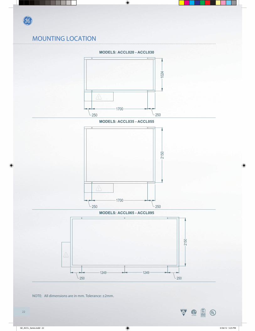
MOUNTING LOCATION
NOTE: All dimensions are in mm. Tolerance: ±2mm.
MODELS: ACCL020 - ACCL030
MODELS: ACCL035 - ACCL055
MODELS: ACCL065 - ACCL095
GE_ACCL_Series.indd 22 3/26/12 5:25 PM
23
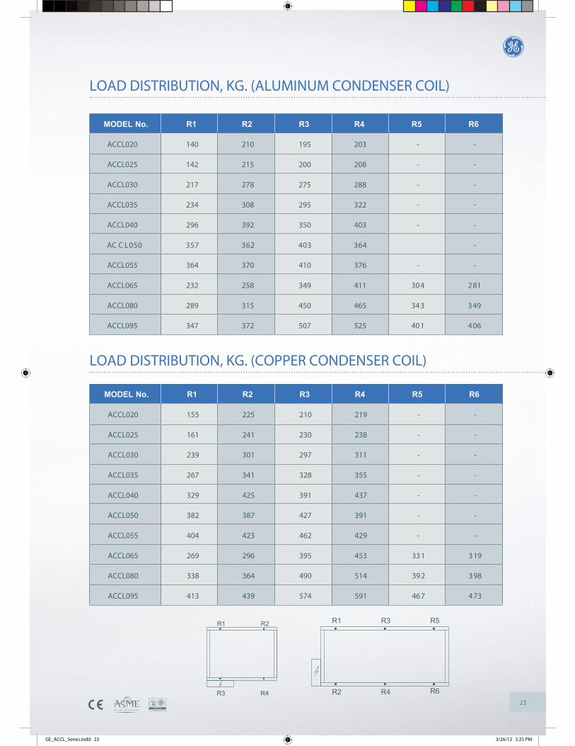
LOAD DISTRIBUTION, KG. (ALUMINUM CONDENSER COIL)
MODEL No. R1 R2 R3 R4 R5 R6
ACCL020 140 210 195 203 - -
ACCL025 142 215 200 208 - -
ACCL030 217 278 275 288 - -
ACCL035 234 308 295 322 - -
ACCL040 296 392 350 403 - -
-463304263753050LCAC
ACCL055 364 370 410 376 - -
ACCL065 232 258 349 411 304 281
ACCL080 289 315 450 465 343 349
ACCL095 347 372 507 525 401 406
R1 R2
R4R3 R2 R4 R6
R1 R3 R5
LOAD DISTRIBUTION, KG. (COPPER CONDENSER COIL)
MODEL No. R1 R2 R3 R4 R5 R6
ACCL020 155 225 210 219 - -
ACCL025 161 241 230 238 - -
ACCL030 239 301 297 311 - -
ACCL035 267 341 328 355 - -
ACCL040 329 425 391 437 - -
ACCL050 382 387 427 391 - -
ACCL055 404 423 462 429 - -
ACCL065 269 296 395 453 331 319
ACCL080 338 364 490 514 392 398
ACCL095 413 439 574 591 467 473
GE_ACCL_Series.indd 23 3/26/12 5:25 PM
24
INSTALLATION & START-UP INSTRUCTIONS
SAFETY CONSIDERATIONS
Improper installation, service, maintenance or use can cause explosion, fi re, electrical shock or other conditions which may cause personal injury or property damage. Check with your nearest GE dealer/sales offi ce for information or assistance. Warning: Before installation or servicing the system, always turn off main power supply. Electrical shock can cause personal injury or death.
SCROLL COMPRESSOR ROTATION
Scroll compressors are designed to operate in single direction only. Hence, care has to be taken to ensure correct rotation when the system is operated. Verifi cation of correct rotation is by observing that the suction pressure drops and discharge pressure rises when compressor run. Reverse rotation results in abnormal sound, as well as, substantially low current draw and by interchanging power supply wire L1 & L3 will correct this problem.
INSTALLATIONSTEP-1: Check equipment and job site
Unpack unit and move to fi nal location taking care not to damage the unit. Remove screws holding the unit to wooden pallet and a� er removing wooden pallet, refi x the screws.
STEP- 2: Installation on a solid, level mounting pad
When installing, allow suffi cient space for airfl ow clearance, wiring, refrigerant piping and service. Allow proper clearance (refer to installation clearance diagram) all around and no obstruction above unit for proper airfl ow. Double the service access when multiple units are installed at one location. On roo� op applications, locate unit at least 6” (152 mm) above roof surface. Place unit above a load-bearing wall, isolate unit and piping set from structure. Use 4”x4”x1” thick rubber/cork mounting pads. Arrange supporting members to adequately support unit and minimize transmission of vibration to building.
STEP-3: Piping connections
Outdoor units should be connected to indoor units using fi eld-supplied piping of refrigerant grade and correct size. The liquid and suction line diameters can be determined from the physical data table. For piping requirements beyond 50 � (15.24 m), obtain information from your nearest GE dealer/sales offi ce.
It is advisable to size piping according to recommended ASHRAE methods. Install piping according to refrigeration standard practice. Run refrigerant pipes as directly as possible, avoiding unnecessary turns and bends. Install refrigerant pipes care-fully to prevent damaging the suction pipe insulation and vibration transmission to the structure.
Compressors are already charged with the required amount of lubricant. There is no need to charge in the fi eld. Make sure that no air & moisture enter the system as easter oil are hygroscopic in nature. The whole system should be leak tested and evacuated before charging the refrigerant.
Outdoor unit connected to factory matched indoor unit
Outdoor unit contains holding charge only. The correct system refrigerant charge for operation is given in the unit name-plate & physical data table when connected with up to 25 � (7.62 m) of fi eld-supplied piping. Check refrigerant charge for maximum effi ciency.
Sweat connection
Use refrigerant grade piping. Service valves are closed from factory when shipped and ready for brazing. A� er wrapping the service valve with a wet cloth, the piping set can be brazed to service valve using either silver rod or silfos rod brazing material. When brazing completed, refrigerant piping and indoor coil are now ready for leak testing. This check should also include all fi eld and factory brazed joints.
Warning: Relieve all pressure before refrigerant system repair or fi nal unit disposal to avoid personal injury or death. Use service ports and open all valves.
GE_ACCL_Series.indd 24 3/26/12 5:25 PM
25
STEP 1: INSTALLATION
A) Please ensure power supply to the unit is as per unit nameplate (Volts/Ph/Hz) requirements.
Caution: Operation of the unit on improper power supply will result in damage to the unit.
Note: Use copper wires of proper rating for all fi eld wiring.
Warning: Before servicing or installation of the unit, always TURN OFF all power to the unit. There may be more than one disconnect switch. Ensure all of them are turned off . Electrical shock can cause personal injury or death.
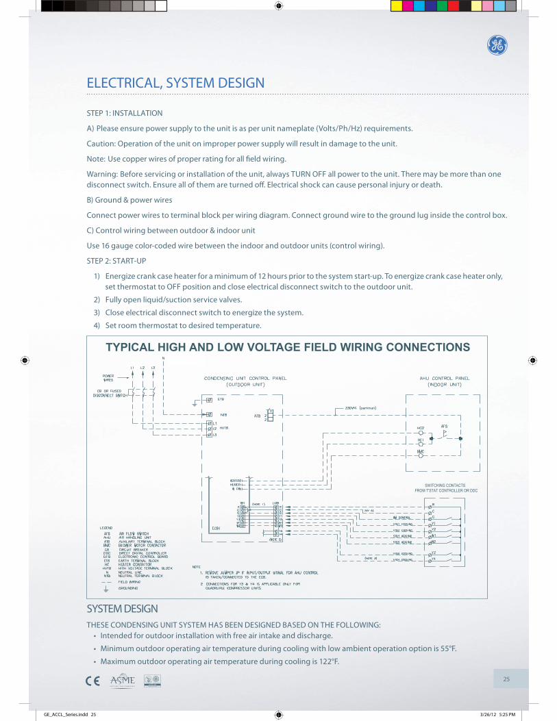
B) Ground & power wires
Connect power wires to terminal block per wiring diagram. Connect ground wire to the ground lug inside the control box.
C) Control wiring between outdoor & indoor unit
Use 16 gauge color-coded wire between the indoor and outdoor units (control wiring).
STEP 2: START-UP
1) Energize crank case heater for a minimum of 12 hours prior to the system start-up. To energize crank case heater only, set thermostat to OFF position and close electrical disconnect switch to the outdoor unit.
2) Fully open liquid/suction service valves.
3) Close electrical disconnect switch to energize the system.
4) Set room thermostat to desired temperature.
SYSTEM DESIGNTHESE CONDENSING UNIT SYSTEM HAS BEEN DESIGNED BASED ON THE FOLLOWING:
Intended for outdoor installation with free air intake and discharge.
Minimum outdoor operating air temperature during cooling with low ambient operation option is 55°F.
Maximum outdoor operating air temperature during cooling is 122°F.
FROM T'STAT CONTROLLER OR DDCSWITCHING CONTACTS
TYPICAL HIGH AND LOW VOLTAGE FIELD WIRING CONNECTIONS
ELECTRICAL, SYSTEM DESIGN
GE_ACCL_Series.indd 25 3/26/12 5:25 PM
Middle East Air Conditioners Co. Ltd.
Middle East Air Conditioners Co. Ltd.P.O. Box 14346 Dammam 31424 KSA
Kingdom of Saudi Arabia| Tel: +966 3 847 2688 Fax: +966 3 847 2931
GE_ACCL_Series.indd 26 3/26/12 5:25 PM