Embed Size (px)
Citation preview

Nahonal Aerwuhcs and Space Adrmn~stration
DESIGN STUDY OF A HIGH
POWER ROTAHi TRANSFORMER
CR- 1 6 8 0 1 2 2
GE-82SDS4222
S. M. WEINBERGER
GENERAL ELECTRIC COMPANY
SPACE D I V I S I U N
P. 0. BOX 8 5 5 5
PHILADELPHIA, PENNSYLVANIA 191 0 1 \.
(NASA-Cd-16@012) D E S I G N S l U D Y OF A H I G H N83- 16630 POWER E O I A R Y TRANSFOEHER (General Electric Co.) 59 p flC AOU/HP A01 CSCL 09C
Un cl as G3/33 08246
PREPARED FOR
NATIONAL AERUNAUTICS & SPACE ADMINISTRATION
NASA-LEWIS RESEARCH CENTER
CONTRACT NAS 3 -23155
https://ntrs.nasa.gov/search.jsp?R=19830008359 2018-07-29T05:47:19+00:00Z

I
General E l e c t r i c Company Space D iv i s ion Val 1 ey Forge, PA
A design study was made on a ~ o t a r y transformer for t ranr fer r i .ng e. lectr ica1 power across a r o t a t i n g spacecraft interface.. The analys is was performed f o r a 100 KW, 20 KHz u n i t having a "pancake" geometry. The r o t a r y trans- former had a r a d i a l ( v e r t i c a l ) gap and consisted of 4-25 KW modules. It was assumed t h a t the power cond i t ion ing comprised o f a Schwarz resonant c i r c u i t w i th a 20 KHz swi tching frequency. The study covered the r o t a r y transformer, mechanical and s t r u c t u r a l design, heat r e j e c t i o n system and d r i v e mechanism provid ing a complete power t rans fe r device. The r o t a r y transformer losses, e f f i c iency , weight and s ize were ccmpared w i t h an ax i a1 (ax ia l symmetric) gap transformer having the same performance require- ments and input cha rac te r i s t i cs which had been designed as p a r t o f a previous program. The "pancake" geometry r e s u l t s i n a h e w i e r r o t a r y transformer p r i m a r i l y because o f i n e f f i c i e n t use o f the core mater ia l . The present r tudy shows t h a t the r a d i a l gap r o t a r y transformer i s a feas ib le approach f o r the t ransfer o f e l e c t r i c a l power across a r o t a t i n g i n te r face and can be implemented using present ly avai lab1 e technology.
i t
j i , I
k. a i -. ?
1. R W Na 2. Ganmmrnt No. CR-168012 .
4. Title and Subtitle
Design Study o f a High Power Rotary Transformer
7. Author(sl
S. M. Weinberger ,
9. kfarming Orgmintion Nuns nd Adba 4
11. Convvt or 08nt No.
NAS-3023155 13. T v ~ of R l p o n nd Priod Covrd
12. Sponsoring Agency Name n d Addrat
Nii t ional Aeronautics & Space Admi ni.s trat i .on Lewis Research Center
17. K ~ ~ W W ~ S (S~ggrrted by Authw(s) I 18. Distribution Statement I ContactlessElectricalPowerTransfer
3. Ruipiwn's Camlog No.
I Report Dln J u l y 1982
6. PIltormimg or@zltion Codr
8. Forfarming Orgnirotion RIpat No.
82SDS4222 10. work unit No.
Contractor Report 14. wvwiq A- codr
I
19. SICur~ty Uamf. (of thts report) 3). k u r ~ t v Clarut. (of thas
1 T i
Cleveland, Ohio 44135 15. Sum1ury No-
Rctary Transformers ; Radial Gap Rotar;~ l ' r~nsfonner; Axia l Gap Rotary Transformer; S l i p Rings
i I .. . ,
Unc lass i f ied - Unl imi ted
- - -
V-30s For sale by the N a l l o ~ l Techn~cal lnformat~on Servlce. Springfield. V ~ r g ~ n ~ a 22161
I Unclassified Unclassi f i e a 1

TABLE OF CONTENTS
TITLE SECTION PAGE NO.
INTRODUCTION
REQUIREMENTS
ROTARY TRANSFORMER DESIGN
3.1 Core Design 3.2 Windings 3.3 Leads 3.4 St ruc tu re 3.5 Adhesives 3.6 Thermal Design 3.7 D r i v e Mechanism 3.8 Power Cond i t ion ing E lec t ron i cs
RESULTS
4.1 Weight 4.2 S ize 4.3 Losses
COMPARISON OF RADIAL AND AXIAL GAP ROTARY TRANSFORMERS
5.1 Weight Comparison 5.2 Comparison o f Losses and E f f i c i e n c y 5.3 S ize Comparison 5.4 D r i ve Mechanism Comparicon 5.5 R e l i a b i l i t y Comparison
RECOMMENDATIONS
CONCLUSIONS
REFERENCES
DISTRIBUTION LIST

LIST OF FIGURES
FIGURE NO.
3-1
TITLE
100 KW Rotary Transformer, Concentric Drive, Four 25 KW Modules
Primary and Secondary Cores
Assembly, Primary, 25 KW Rotary Transformer Module
Assembly, Secondary, 25 KW Rotary Transformer Module
25 KW Module Deta i l Rotary Transformer
Assembly Detai 1 Transformer Modules
Modular Heat Pipe Concept
Integral , Structural/Heat Pipe Csncept
Prel iminary - Configuration #1 1 OOKW Rotary Transformer, Offset Drive, Four 25 KW Modules
Prel iminary - Configuration t 2 100 KW Rotary Transformer, Offset Drive, Four 25 KW Modules
25 KW Modul e-Resonant Converter
LIST OF TABLES
TABLE NO.
Material Selection C r i t e r i a
Transformer Module Magnetic Parameters
Transformer Module Winding Design
Transformer Module Temperature Characterist ics
PAGE NO.
9

. SUmARY
A study was made of a 100 KW rot>.-y power transformer for transferring electrical
power across a rotating spacecraft interface between solar arrays and the spacecraft
body. The rotary transformer had a "pancake" geometry, i.e., a large diameter and
short length. This was accomplished by utilizing a 4-25 KW transfomr modules,
with the modules having radial (vertical gaps) and arranged concentrical ly, one
inside-another. The study covered the rotary transformer, mechanical design,
strictural design, heat rejection system, aid drive mechanism. A comparison was
made of the axial jap (axial symmetric) rotary transformer and power transfer device
designed as part of "Preliminary Design Development of 100 KW Power Transfer Device",
Report NASA-CR 165431.
This study showed that a 100 KW radial gap rotary transformer having a "pancake"
geometry is feasible. The radial gap transformer is heavier than the axial gap,
weighing 75.7 lbs. as compared with 46.4 Ibs., principally due to the less efficient
use of the core material in the modules. Some weight reduction could be attained
by a more detailed design analysis or by application of advanced materials. The
weight of the rotary power transfer device with attendant equipment for the radial
gap configuration is 225.4 lbs., while that of the comparable axial gap device is
191.8 lbs. The rotary transformer assembly weighs approximately one-half of the weight
of the complete power transfer device and the rotary transformer contributes about
one-third of the total weight. The size of the radial gap transformer is 17.3 inches
diameter a ~ d 2.625 inches long; and that of the rotary transformer assembly i: 17.3
inches diameter and 6.6 inches long.
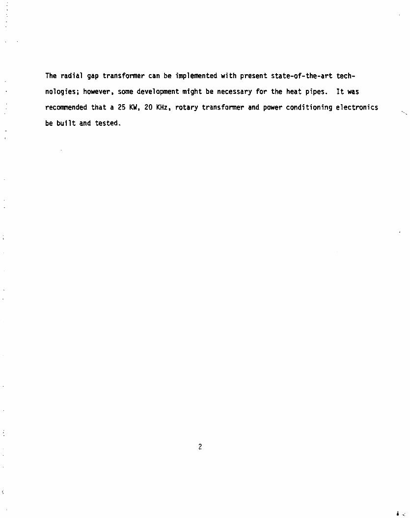
The radial gap transformer can be implemented with present state-of-the-art tech-
nologies; however, some development might be necessary fo r the heat pipes. I t was
recomnended that a 25 KW, 20 KHz, rotary transformer and power conditioning electronics
be b u i l t and tested.

1.0 INTROMCTION - The power requirements f o r fu tu re spacecraft appear t o he i n the magnitude o f 100 KW
t o 1 MU. Spacecraft which have sun-oriented arrays requ i re a means of t r a n s f e r r i n g
the power across the r o t a t i n g in te r face between the so la r arrays and the spacecraf t
body. In present day spacecraft where the power requirements are several k i lowat ts ,
the power t ransfer i s accomplished by brushes r i d i n g on s l i p r i ngs . Techniques other
than brushes and s l i p r i n g s have been addressed t o meet the needs fo r h igher power
as we l l as the necessi ty f o r h igher voltages and long operat ional l i f e . Typ i ca l l y
advanced a p p l i c a t i o r s f o r r o t a r y j o i n t s w i l l r equ i re a 10 year i i f e t ime and work
through 50,000 cyc les .
A study of non-contacting , a1 te rna t i ng cur ren t power t r a n s f e r devices was perfomled
i n the "Pre l iminary Design Development o f 100 KW Rotary Power Transfer Device",
Report NASA CR-165431 under Contract NAS 3-22266. This study showed t h a t a r o t a r y
transformer was a feas ib le concept f o r the t r a n s f e r o f e l e c t r i c a l power. As p a r t
of the study, a 100 KW r o t a r y power t r a n s f e r device was designed. The power t rans-
f e r device consisted o f a r o t a r y transformer, power cond i t ion ing e: ect ronics, d r i v e
mechanism and heat r e j e c t i o n system. The r o t a r y transformer had an a x i a l gap ( a x i a l
symnetric) and u t i l i z e d 4-25 KW modules placed along the sha f t ax is . Although t h i s
approach i s q u i t e feasib le, i t s inherent geometry i s one o f r e l a t i v e l y long length
and small diameter.
This study was undertaken t o i nves t i ga te a r a d i a l gap ( v e r t i c a l gap) r o t a r y t rans-
former and t o compare i t s cha rac te r i s t i cs w i t h t h a t o f the a x i a l gap conf igura t ion .
The r a d i a l gap r o t a r y transformer was t o have a pancake conf igura t ion : l a rge diameter
and shor t length, a geometry could be more favorable from the aspect o f spacecraft
considerat ions. The pancake conf igura t ion would be achieved by us ing r a d i a l gap

transformer modules stacked r a d i a l l y one-inside-another. This appraoch l's a 1 i t t l e
more complex than t ha t o f the ax ia l gap transformer. The major concerns w i t h the
rad ia l gap geometry are the heat re jec t ion system, the ineffici'ent use o f the core
material resu l t i ng from the large diameter, and the necessity f o r havi'ng four modules,
each having d i f ferent cores and windings.
An addi t ional pa r t o f t h i s study was a comparison o f the rad ia l anJ ax ia l ro ta ry
transformers. This comparison cove~ed wei.ght, size, losses, e f f i'ciency and re1 iabi'l i t y
focusing on the character is t ics o f the 25 KW modules as wel l as the 100 KW assembly.

2.0 REQUIREMENTS
The requirements f o r the Rotary Power Transfer Device were der ived from LeRC, some
cf the recomnendations presented by the General Dynamics "Study of Power Management
Far Orb i ta l Mu1 t i - 100 KWe Appl icat ions", NASA CR-159384; and consistency w i t h "Pre-
I i m f nary Design Development o f 100 KW Rotary Power Transfer Device", NASA CR-165431.
Tke requirements which were used as guidel ines are as fol lows:
Input from Solar Ar ray
Power 100 KW
Voltage 440 V51ts
Output from Rotary Power Transfer Device
Voltage 1000 Vo l ts
Frequency 20 KHz
Pcwer Condit ioning E lec t ron ics - Resonant C i r c u i t (Schwarz)
Rotary Transformer
Power 100 KW
Input Voltage 400 Vo l ts
Input Current 70 Amps
Output Voltage 1000 Vol t s
Frequency 20 KHz
Inductance 75 rH
Conf i g r u a t i o n Radial Gap 4-25 KW modules Two p a r a l l e l secondary windings per module

Rotational Period
Ef f ic iency
Environment
90 minutes t o 24 hours
Greater than 95%
Shutt le Launch
Tempersture
- Non-operati ng -20' t o 80°C
- Operating 80' Heat Sink, Rotary Transformer
60' Heat Sink, Power Conditioning Electronics
5 Years L i f e -

3.0 ROTARY TRANSFORMER DESIGN
The r o t a r y transformer t rans fe rs e l e c t r i c a l power across the spacecraft in te r face
by means o f electromagnetic coupl ing between the transformer primary and ;,.:,onci,. I .
The transformer pr imary cons is ts o f a core and winding, and i s mechanical !y attached
and connected e l e c t r i c a l l y t o t he s o l a r a r ray through power cond i t ion ing e lec t ron ics .
The transformer secondary, a l so cons is t ing o f a core and winding, i s mechanically
attached t o the spacecraft and i t s e l e c t r i c a l power i s de l i vered t o the spacecraft
load. The e l e c t r i c a l so la r a r ray power i s converted from dc t o 20 KHz ac by the power
cond i t ion ing e lec t ron i cs which i s a Schwarz resonant c i r c u i t . The heat which i s
2 generated by I R and core losses i n the transformer primary and secondary i s t rans-
ported by heat pipes t o thermal >e jec t i on surfaces. Rotat ional capdbi l i t y ranging
from one revo lu t i on per day t o one r e v c l u t i o n every 90 minutes i s provided by a
stepper motor, speed reducer, and associated d r i v e e lec t ron ics . . The r a d i a l gap ( v e r t i c a l gap) transformer module conf igurat ion i s more complex than
the prev iously s tudied a x i a l gap ( a x i a l symmetric) module geometry. I n the a x i a l
gap conf igurat ion, a1 1 modules were i d e n t i c a l : cores, windings, resistance, i n -
ductance and losses were the same. I n the r a d i a l yap conf igbrat ion, the modules being
"stacked" r a d i a l l y on each o ther are a l l d i f f e ren t . This means t h a t each transformer
module has a d i f f e r e n t core, d i f f e r e n t winding, and d i f f e r e n t losses. There i s noth ing
inherent ly wrong w i t h t h i s , bu t i t does add t o the complexity o f the approach.
A more s e r ' ~ u s problem w i t h the r a d i a l gap conf igura t ion i s i n the heat r e j e c t i o n
system. I n both r a a i a l and a x i a l gap transformers, heat pipes are x e d t o t ranspor t
the heat f rov the transformer modules t o the heat sink. I n the a x i a l gap, the heat
pipes t ranspor t the heat only i n one d i rec t i on , a x i a l l y , p a r a l l e l t o the s h a f t ax is .

. I n the r a d i a l gap conf igura t ion , the problem i s more d i f f i c u l t because the transformer 1
i
cores have d i f f e r e n t diameters. Ax ia l heat pipes could be used d i r e c t l y connect ing . . .
each i nd i v idua l module t o the heat sink; however, t h i s wauld lead t o a complex . .
t .
s t ruc tu re and excessive weight. An a l t e r n a t i v e heat r e j e c t i o n method e n t a i l i n g a
combination o f r a d i a l and a x i a l pipes. The r a d i a l heat pipes would be attached t o the
transformer cores and would t r a n s f e r heat r a d i a l l y t o the a x i a l heat pipes, and the 7
a x i a l heat pipes would then t rans fe r heat a x i a l l y t o the heat r e j e c t i o n surfaces. The
r a d i a l and a x i a l heat pipes could be separate, bu t t h i s would lead t o a l a rge thermal
gradient between the two sets o f pipes a t t h e i r in te r face . This thermal gradient
could be reduced by having a l a r g e contact surface area but t h i s would e n t a i l hzat
p ipe overlap and a subs tant ia l weight increase. The proposed s o l u t i o n i s t o make the
r a d i a l and a x i a l heat pipes i n t o a s i n g l e i n t e g r a l u n i t . This i s a more complex heat
p ipe bu t would r e s u l t i n a b e t t e r ove ra l l design -
The se lec t ion o f mater ia ls fo r the r o t a r y transformer i s q u i t e impor ta r t 2 they
j u s t be compatible w i t h each o ther and i n the func t ion t h a t they are expected t o
perform. Table 3.1 shows the mater ia ls used on the r o t a r y transformer, the reasons
f o r t h e i r se lec t ion and t h e i r l i m i t a t i o n s . I t prcvides the r a t i o n a l e f o r the mater ia ls
chosen fo r the various design areas.
The design conf igurat ion f o r the r o t a r y transformer i s shown i n F igure 3 . i , 100 KW
Rotary Transformer. This f i g u r e shows a complete r o t a r y power t rans fe r device: r a d i a l
gap r o t a r y transformer modules, s t ructures, heat pipes and d r i v e mechanism. The over-
a l l con f igura t ion i s a "pancake": a l a rge diameter and small length.

è able 3.1. Mater ia l Select ion C r i t e r i a
Design Area
Magnetic
E l e c t r i c a l
Mechani ca l
Thermal
Mater ia l
MN 60 F e r r i t e
L i t z Wire Nyl eze
Inconel Structures
.-
Inconel heat pipes, r a d i a l / a x i a l
Radiator
Thermal 1 y conducting epoxy
Reason f o r Sel ec t i on
a) I s o t r o p i c b ) Low core l oss c ) High permeab i l i t y
a) Low eddy cur ren t 1 oss
b) Solderable
a) Coe f f i c i en t o f expansion
b ) Non-magnet12
a) Coe f f i c i en t of expansion
b ) Thermal gradients
Thermal d i s s i p a t i o n
Thermal conduc t i v i t y
L im i ta t i ons
a) Flux densi ty/temperature b! Coef f i c ien t o f expansion c ) Low thermal conduc t i v i t y d ) Low s t rength
a ) Connections
b) L i fe/ temperature
a) Fabr ica t ion
b) Weight c ) A v a i l a b i l i t y
a) Weight
b) Avai l a b i 1 i t y
a) Size, weight
a) Shear s t rength b ) Bond-1 i n e thickness

L PAGE m OR\G\N fi kt\fl of POOR Q
I EOL DOUX FRAIv16 i 1:


. 3.1 CORE DESIGN
The pr imary and secondary transformer cores are fab r i ca ted from MN 60, a maganese
z inc f e r r i t e mater ia l made by Ceramic Magnetics, Inc. This mater ia l was selected
because o f i t s being magnetic i s o t r o p i c and having low core losses. The use o f any
f e r r i t e mater ia l imposes magnetic, thermal and mechanical cons t ra in t s on the r o t a r y
transformer design. Some o f the proper t ies o f MN60 and t h e i r a f f e c t s a re as fo l lows:
Property Ef fects
Maximum operat ing f l u x dens i ty i s a func t ion o f temperature.
Temepra t u r e B max ("c) (Gauss)
75 3500 1 00 3000 125 2400 1 50 1400 185 0 (Curie
p o i n t )
Coe f f i c i en t o f thennal expansion.
Low thermal conduc t i v i t y . K = 3.6 ~ ~ u / h r / f t ~ / ' ~ / f t
hlechanically weak
Core s i z e a f fec ted operat ing temperature. Thermal run-away could occur
Structure, s h a f t heat pipes cannot be fab r i ca ted from aluminum o r t i tan ium, Inconel used.
Large c i rcumferent ia l thermal gradients i n cores i f few heat pipes used.
Minimum al lowable thickness, 0.2". Cores t h i c k e r than requ i red fo r mag- n e t i c reasons.
The primary and secondary core geometries are shown i n Figure 3.2. They are f a b r i -
cated from r i ngs having a c i rcumferent ia l groove cu t i n t o t h e i r s ides t o accomno- i i 4 date the windings. Since the maximum diameter o f r i n g which can be e a s i l y fabr ica ted
i s about e igh t inches, transformer modules having r i n g diameters i n excess o f e igh t
inches would be made by f a b r i c a t i n g the r i n g i n segments. These segments would then . .


be bonded together t o form the core assembly. The length o f gap hetween the segments
would not be c r i t i c a l because they are not i n the path of the magnetic f l ux , however,
i t should be kept small i n order t o minimize the reluctance torques which a r i se when
the gaps i n the primary and secondary cores are i n alignment. The power leads t o the
windings would be brought out through s l o t s cu t i n the cores.
The widths o f the primary and secondary cores were kept ident ica l , 1.35 inches and
1.25 inches, respectively, i n order t o s imp l i f y the mechanical and s t ruc tu ra l design
o f the ro ta ry transformer. Keeping the core widths iden t i ca l i s not optimum from
the aspect o f magnetic c i r c u i t design since the la rger diameter modules do not require
the same dimensions as the smaller diameter modules t o maintain the required f l ux
density. I f the core widths were establ ished s t r i c t l y by magnetic design c r i t e r i a ,
the s t ruc ture would be la rger and heavier than necessary so t ha t there would be no
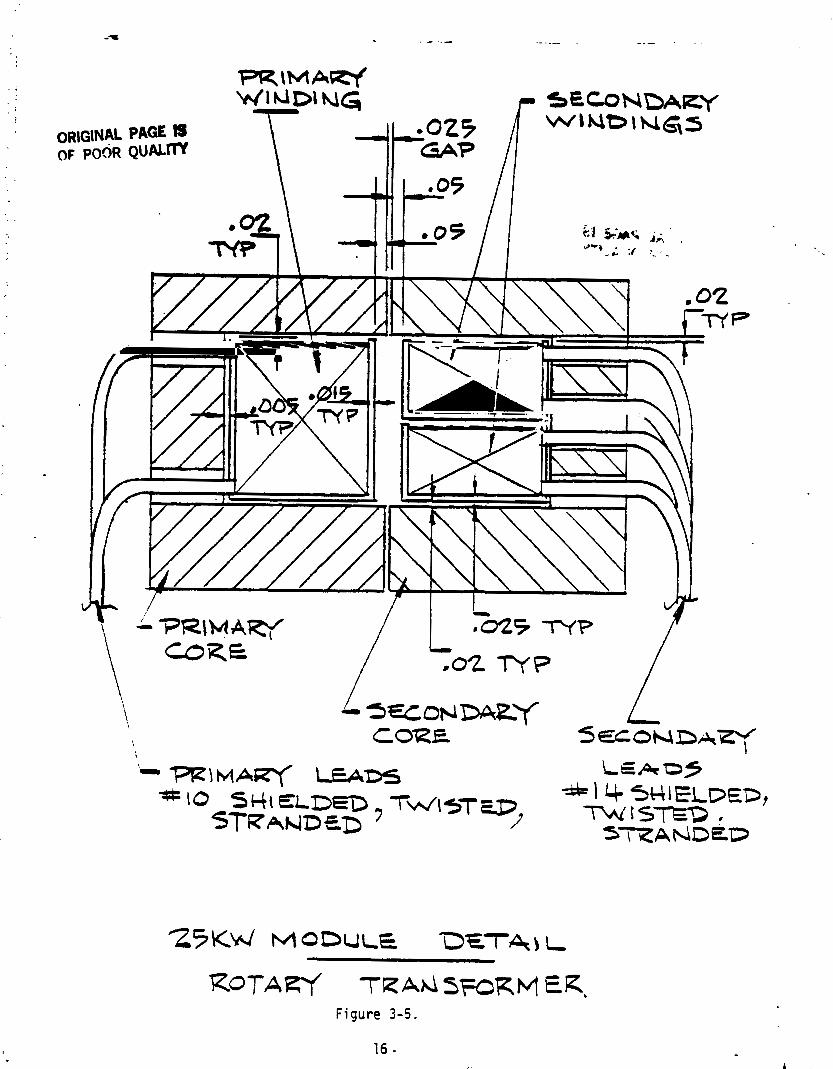
advantage attained. . :n Figures 3.3 and 3.4, 25 KW Rotary Transformer Module, Prfmary and Secondary,
respectively, show the winding and core assemblies, and the mater ia ls used. The
25 KW Module Configuration i s shown i n Figure 3.5. The Assembly Detai 1 of the cores,
winding, heat pipes and structure i s shown i n Figure 3.6.
Tabln . -2, Transformer Module Magnetic Parameters, shows the magnetic character is t ics
c , the transformer modules. A1 though the f e r r i t e core mater ia l can operate a t f l u x
densi t ies up to approximately 2,000 gauss a t 125OC, the actual f l u x densi t ies are
rruch less, c:*imarily because o f mechanical constraints. For example, the f l ux densi - t i e s i n Module 4 range between 664 gauss and 1,621 gauss, considerably less than
~ , 0 0 0 gauss.

CORE MAT=\AL :- FERRITE M d GO
Figure 3-3.

Figure 3-4.
' OR~G~NAL PAGE PI OF PO& Q U A L ~
-\MAW SECONDARY W i N D I N G S
L J ~ o N D A E ~ CORE
L S E C O N D A ~
ROTAW T K A ~ ~ W R M E R , Figure 3 - 5 .

ASSEMBLY DETAL
Figure 3-6.
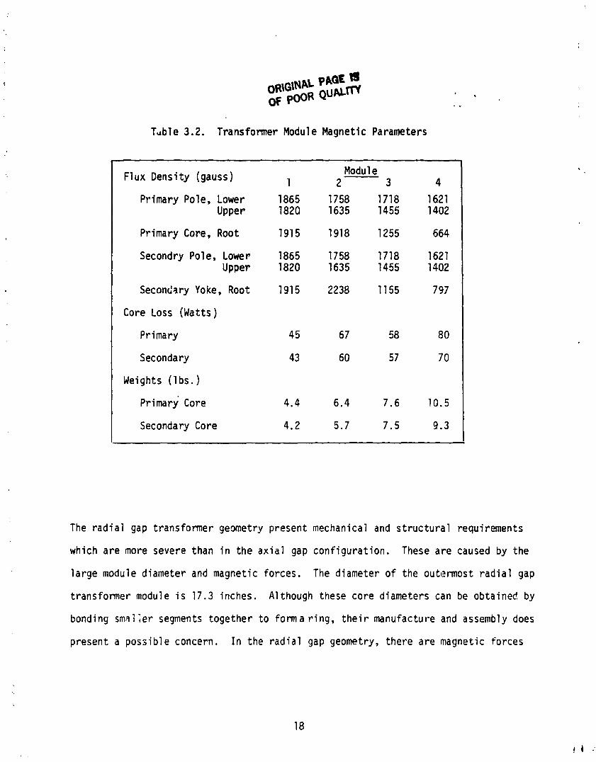
Table 3.2. Transformer Module Magnetic Parameters
F lux Densi ty (gauss ) Modul e 1 2 3 4
Pr imary Pole, Lower 1865 1758 1718 1621 Upper 1820 1635 1455 1402
Pr imary Core, Root 1915 1918 1255 664
Secondry Pole, Lower 1865 1758 1718 1621 Upper 1820 1635 1455 1402
Secondary Yoke, Root 1915 2238 11 55 7 97
Core Loss (Wat ts)
Pr imary 45 67 58 8 0
Secondary 43 60 5 7 70
Weights ( l b s . )
pr imary Core 4.4 6.4 7.6 10.5
Secondary Core 4.2 5.7 7.5 9.3
The r a d i a l gap transformer g e m e t r y present mechanical and s t r u c t u r a l requirements
which a r e more severe than i n the a x i a l gap con f i gu ra t i on . These a r e caused by the
l a r g e module diameter and magnetic forces. The diameter o f the outermost r a d i a l gap
t ransformer module i s 17.3 inches. A1 though these core diameters can be obta ined by
bonding sma 1 ;er segments toge ther t o form a r i n g , t h e i r manufacture and assembly does
present a poss ib l e concern. I n the r a d i a l gap geometry, t he re a r e magnetic forces

present i n the a x i a l d i r e c t i o n tending t o p u l l the modules together. The magnetic
forces are estimated t o be approximately 130 lbs. It i s des i rab le t o keep the
length o f gap between the primary and secondary cores as small as possib le t o m in i -
mize the magnetizing current . A gap length o f .025" was selected as the minimum
a t ta inab le based on mechanical and s t r u c t u r a l considerat ions. It i s , therefore,
necessary t o have a s t ruc tu re r i g i d enough t o mainta in the gap length and i t s
para1 l e l ism.
3.2 WINDiNGS
The i n p u t power t o the r o t a r y transformer o r i g i n i a t e s i n the so la r a r ray as DC and i s
converted by a Schwarz resonant c i r c u i t power cond i t ion ing t o 20 KHz AC. The output
o f the secondary winding o f the transformer feeds i n t o the spacecraft a t a stepped-!:?
voltage o f 1,000 vo l t s . I n order t o p e r m i t some degree o f f l e x i b i 1 i t y and redundancy,
the secondary was designed having two independent windings, each capable o f supplying
12.5 KW per module. The use o f the Schwarz resonant c i r c u i t imposes the inductance
requirement o f 75 pH f o r each transformer module. I f the inductance i s d i f f e r e n t
from t h i s , there w i l l be a change i n the swi tch ing frequency o f the resonant c i r c u i t .
A t rade-off was made t o determine the hest wi.nding design. Spme o f the winding
parameters which were addressed included number of turns, wipe si'ze, t u r n size, losses,
and inductance. Generally, as the number of primary tu rns i s increased, the inductance,
copper loss, winding area and number of secondary tu rns increase wh i le the core cross
sect ion area and f l u x densi ty decrease. For mechanical reasons, i t i s des i rab le t o
have primary and secondary leads come out the same s ide of the core, the number o f
layers must be even. I n add i t ion , the number o f primary and secondary tu rns must be
an in teger .

O R I G I F ~ ~ L PAGE K3 OF POOR QUALm *
The vo l tage r a t i o between t h e p r ima ry and secondary windings a f fec t t h e n u m k r of
t u r n s which can be used on t he p r imary winding. The t u rns r a t i o between t he pr'mary
and secondary i s de f ined as t h e t u rns r a t i o :
Secondar Vol t a e Turns Ra t i o = Yo1 tage Ra t i o = Pri,,,aryyVol tag:
Turns R a t i o = = 2.5
The f o l l o w i n g shows t he number of t u rns on t he primary and secondary windings which
a r e s a t i s f a c t o r y and which a re n o t s a t i s f a c t o r y .
Primary Turns (NP
16
15
14
13
Secondary Turns (Ns) (Ns = 2.5 Np)
40
37.5
35
32.5
Comnen t s
S a t i s f a c t o r y
Unsa t i s f ac to r y Np i s odd Ns i s a f r a c t i o n
Unsa t i s f ac to r y Ns i s odd
Unsa t i s f ac to r y Np i s odd Ns i s a f r a c t i o n
33
11 27.5
Sa t i s f ac to r y
Unsa t i s fac to ry Np i s odd
' 1 0
14s i s a f r a c t i o n
Unsa t i s f ac to r y
25 1 Ns i s odd
Because o f the high frequency transformer operation, and the necessi ty o f keeping
the eddy cur ren t losses t o a minimum, the pr imary and secondary windings were designed
w i t h insulated, stranded, transposed conductor i n the form o f L i t z wire. L i t z w i re i s
ava i l ab le comnercial ly over a wide range o f s izes from spec ia l t y w i re manufacturers.
Two major disadvantages o f L i t z w i r e are the reductior; i n winding space f a c t o r re -
s u l t i n g from the st randing and t ransportat ion, and the design connector t o t he power
leads. The L i t z w i re conductor i n s u l a t i o n w i l l be heavy . , l rethane w i t h ny lon
overcoat w i t h the t rade name Nyleze. This i s a solderab~l- .; - e t w i re w i t h gotd
winding cha rac te r i s t i cs and i s compatible w i t h most impregnants.
The requirements o f the Schwarz resonant c i r c u i t de f ine an i npu t inductance o f each
module as being 75pH. I n the a x i a l gap r o t a r y transformer, the inductance was
achieved by us ing a magnetic shunt whose geometry could be changed. - Magnetic shunts
were no t used i n the r a d i a l gap design becasue o f the weight and the d i f f e r e n t s izes
necessary f o r each module. Instead, the requi red inductance was obtained by the
se lec t ion o f the number o f turns and the winding s l o t geometries o f the primary and
secondary cores.
The winding design f o r each o f the transformer modules i s shown i n Table 3.3. lne
winding design f o r each module i s d i f f e r e n t 3s the d i r e c t r e s u l t o f d i f fe rences i n
module diameter and r e f 1 ects the requirements o f inductance, losses and temperature
r i se .

Turn Size .2" x .2" .161" x .244" .157" x .266" .2" x . 2 " Resi s t w c e (ohms) .0148 dc ,0157, dc ,0197, dc .0257, ac
@ 135°C .0192 ac .0203, ac .0238, ac .0291, ac
1. Rac (Matts) 9 5 99 134 143
Inductance 37.9 38.4 37.0 35.7
Table 3.3. Transformer Module Winding Design
Copper Weight (1 bs. ) 1.2 1.2 1.7 2.1
1 t !
I
I Secondary Winding I
- Module I 2 3 4
Primary Winding 12 8 8 8 TurnsIWinding 3 4 2 2
Turns/Layers 4 2 4 4
Wire Size, Stranding #38, 2025 #38, 1980 #38, 2100 #38, 2025 ,
Windings 2 2 2 2
Wire Size, Stranding f38, 300 #38, 330 #38, 360 #3&, 760
/ Turn Size .057"x .113" .053" x .131" .O7OH x .lr19I1 .053" x .032"
Resistance (ohms) .125, dc .118, ds ,138, dc ,181, dc 1 135OC .115, ac .142, ac . I61 , ac .200, ac
12 Rac (wat ts ) 9 1 89 101 125
I Inductance (uH) 34.3 38.4 36.5 38.9
j Copper Weight ( i b s . ) 1.5 1.7 2.6 3.1

3 . 3 LEADS - The power leads fo r the pr imary and secondary w i l l cons is t o f insu la ted stranded
conductors. The leads w i 11 be shielded and used i n the form o f tw is ted p a i r s t o
minimize electromagnetic in ter ference. The primary leads w i 11 be 110 AWG wh i l e the
secondary w i l l be 114 AWG, the d i f fe rence being due t o the lower cur ren t ca r r y ing
requirements o f the secondary.
3 . 4 STRUC I URE
The basic s t ruc tu ra l elements o f the r o t a r y transformer assembly are r ibbed f langed
d isks having i n t e g r a l annular pos i t i on ing r ings . Two o f these d isks are used, one
fo r the primary transformer modules and the second f o r the secondary modules. The
transformer module cores are posi t ioned r a d i a l l y on the d i sk by the annular r i n g s and
are bonded t o both the r i n g s and d isk. The heat pipes are a lso attached t o the f langed
d isks by bonding a i d mechancial fasteners. Bonding i s essent ia l t o p rov id ing a good
t.~ermal path between the transformer modules and the heat pipes. The primary s ide o f
the s t ruc ture i s connected t o the so la r array through a d r i v e shaft which i s an
i n teg ra l pa r t o f the d isk . The secondary s ide i s attached t o the spacecraft by a
s t ruz tu ra l i n te r face flange. The so la r array i s d r iven through a preloaded duplex
p a i r o f bearings and a s ing le row b a l l bearing. The primary and secondary transformer
leads are brought out through a s l o t I n the s t r u c t : ~ r e . The design o f the s t ruc tu re
must acc~rnmodate the ax ia 1 magnetic forces present and the small clearance between
the primary and secondary por t ions o f the r o t a r y transformer.
I t would be desi rable t o fab r i ca te the s t ruc tu re from aluminum f o r the aspect of
weight, ease o f f ab r i ca t i on arid ~ t e r i a l a v a i l a b i l i t y . However, because o f d i f - ,
f e r e n t i a l expansion between the core and heat pipe mater ia ls and the necessity t o

mAL PAGE ?!J OF P ~ O R QUum
t r ans fe r heat across epoxy bonds, alumi~num i-s no t a sat is factqpy mater ia l . The
fo l lowing t a b l e shows a comparison o f the thermal expansipn and thermal c h a r a c t e ~ i ~ s t i c s
of t ransformer core and s t r u c t u r a l mater ia ls .
Thermal Ex ansion Thermal Conduct iv i ty (Per 01 BTU hs / f t2 t0F/ in
MN 60 F e r r i t e 11.5 x 43.5
Inconel 702 12.1 x l og6 81 .O
722 12.1 x l o - 6 102. Q
X750 12.6 x 83.0
A1 umi num 6061 23.4 x 1 Q70
Sta in less Steel 302 17.3 a 113.0
305 16.5 x 113.0
309 14.9 x lQ8.0
31 0 14.4 x lo-' 98.Q
Titanium 6Al-4V 9.0 x 50.0
The best approach consis ts o f Inconel s t ruc ture , Inconel heat pipes i n conjunct ion
w i t h the MN 60 f e r r i t e core. The major disadvantages of Inconel i s i t s density,
d i f f i c u l t i e s o f f a b r i c a t i o n and poor thermal conduct iv i ty .
The adhesives w i l l be used i n the r o t a r y transformer as fo l lows:
Usage Adhesi ve Func t i on
Core t o S t ruc ture Eccobond 285 ( F i 1 l ed ) Mechanicai .i Thermal Winding Eccobond 45 (Unf i 1 l e d ) Mechanical & E l e c t r i c a l Bobbin t o Core Eccobond 285 ( F i 1 l ed ) Mechanical & Thermal Heat Pipes t o S t ruc ture Eccobo~d 285 ( F i 1 led) Mechanical & Thermal
Although f i l l e d epoxies necessi tate a t h i c k e r bond-l ine than u n f i l l e d ones, the
thermal res is ts i ice t o heat f low o f the heat f low path through the f i l l e d epoxy i s
less than t h a t o f u n f i l l e d epoxies. Therefore, f i l l e d epoxies w i l l be used i n
c r i t i c a l heat f low paths.

3.5 ADHESIVES
Epoxy adhesives func t i on - in the r o t a r y transformer t o bond par ts togehter and t o
funct ion as a heat conducting j o i n t . A degradation i n e i t h e r t h e i r mechanical
cha rac te r i s t i cs o r t h e i r thermal p roper t ies could adversely a f f e c t the performance
of the transformer. Two types o f epoxy adhesives are used i n the r o t a r y transfonner,
u n f i l l e d and alumina f i l l e d . The alumina f i i l e d epoxy i s used where required t o
provide a good thermal path wh i le the u n f i l l e d epoxy i s used when good thermal
conduct iv i ty i s no t requirea. Un f i l l ed epoxies have h igher band strength, u t i l i z e
a th inner bond 1 i ne and have poorer thermal conduct iv i ty then f i l l e d epoxies.
Because o f the inherent s ize o f the f i l l e r p a r t i c l e s f i l l e d epoxies require a bond
l i n e thickness o f about .01OU.
The fo l lowing i s a sumnary o f the cha rac te r i s t i cs o f the adhesives being considered
i n the r o t a r y transformer: Eccobond 285 Eccobond 45
Alumina F i l l e d Epoxy U n f i l l e d Epoxy
Shear Bond Strength ( p s i ) 21 00 31 00
F l e x i b i l i t y R i s i d Adjustable
Thermal Conducti v i t y ( ~ ~ u / h r / f t ~ / " ~ / i n )
Thermal Expansion Coe f f i c ien t (1c61°c)
15
D i e l e c t r i c Strength (vol ts /mi 1 )
Service Temperature - .. ("C max)

3.6 THERMAL DESIGN
The thermal design i s o f great importance s ince i t determines the o v e r a l l s izc ,
weight and losses o f the r o t a r y transformer. Heat i s generated i n the r a , a r j t rans-
2 former from I R losses i n the windings and from core l oss i n the f e r r i t e core. The
magnitude of these losses can be varied: increasing the cross sec t ion o f the copper
2 i n the windings w i l l decrease the I R loss,while decreasing the f l u x dens i ty i n the
core w i l l decrease the core losses. The pena l ty f o r doing t h i s i s increased s i z e and
weight o f the r o t a r y transformer. There are temperature-1 im i t ed pa r t s i n the
r o t a r y transformer: windings and cores. The winding temperature i s 1 i f e - 1 imi ted:
the h igher the winding temperature, the shor te r i t s l i f e . I f the winding te rpera ture
i s kept a t 138OC, i t w i l l have a f i v e year l i f e ; wh i l e a t 145OC it w i l l be reduced t o
2.3 years. Core temperatures are more serious s ince an excessive temperature i n the
core can lead t o thermal run-away i n the transformer. Core temperatures i n excess of
125°C resu l t i n 1 ower core magneti c permeabi 1 i ty . Reduced core permeabi 1 i t y w i 11 i n-
crease the t r a n s f e r magnei t iz ing cur ren t which, i n tu rn , w i l l increase the winding
2 I R losses f u r t h e r increasing the core temperature. The f i n a ? r e s u l t w i l l be thermal
run-away.
The r o t a r y transformer thermal system i s based on heat generated i n the
being t rans fer red by conduction through the w i g d i n ~ s and cores t o heat pipes placed
on the back o f the cores, and which t rans fe r the heat t o thermal rad ia tors . It i s as-
sumed t h a t there i s no thermal path between the pr imary 2nd secondary po r t i ons o f the
transformer.

The losses i n the primary r o t a r y transformer and secondary are 721 watts and 636
watts, respect ive ly . Four heat pipes each having a diameter o f 1/2 i t c h have suf-
f i c i e n t capacity t o remove these losses. However, i f fou r heat pipes o f t h i s
s i ~ e were placed on the back o f transformer cores there would be la rge circur,, - f e r e n t i a l thermal ~ r a d i ~ n t s . These la rge thermal gradients are the --;~l+ 3f the
poor thermal conductivities ana long thermal paths o f small cross sect ional area
i n the f e r r i t e core mater ia l and Inconel s t ructure. Large c i rcumferent ia l thermal
graafent are undesirable because they w i l l r e s u l t i n hot spots i n the winding and
core r e s u l t i n g i n l oca l i zed temperatures i n excess r,f those desired. I n add i t i cn ,
the f a i l u r e o f one o f the heat pipes would be serious.
These concerns w i t h the thermal design are e l iminated by using 12 wedge-shaped heat
pipes covering most o f the core area thus e l im ina t ing both the problems o f thermal
gradients and producing a higher degree o f redunaancy. These heat pipes provide the
r a d i a l t rans fe r o f heat from the cores t o the shaf t . A x i a l l y , heat t ransfer i s
accompl ished by c i r c u l a r heat pipes which are i n t e g r a l w i t h the r a d i a l wedge-shaped
ones. The r a d i a l and a x i a l heat pipes w i l l be grooved w i t h a w i re mesh o r
s in tered wick ac t i ng as the t r a n s i t i o n between them. This approach i s shown i n
Figure 3-7, Modular Heat Pipe Concept.
The heat pipe design i s complex fo r several reasms : heat must be t rans fer red i n
two d i rec t i ons , r a d i a l and a x i a l ; the r a d i a l heat pipe requires converging grooves;
a t r a n s i t i o n i s between the r a d i a l and axla1 heat pipes i s necessary; and the heat pipe
mater ia l should ~e Inconel. Some development e f f o r t would probably be required f o r
the heat pipe but the suggested approach appears feasib le.


An a l t e r n a t i v e conf igura t io !~ was considered i n which the heat p ipe and the s t ruc tu re
were one i n t e g r a l u n i t . This would prov ide subs tant ia l weight advantages s ince heat
pipe would be performing a dual funct ion. A1 though t h i s a p p r ~ ~ c h was deemed t o have
mer i t , i t was n o t used because the desi'gn would be more complex and would no t prov ide
s u f f i c i e n t r e l i a b i l i t y i n the event of a heat pi'pe f a i l u r e . The i n t e g r a l , s t r u c t u r a l /
heat p ipe concept i s shown i n Figure 3.8. 1
The temperature o f the r o t a r y transformer pr imary and secondary cores and windings
were ca lcu la ted fo r each module. The temperztures f o r the inner (c loser t o the
s h a f t ) modules tended t o be h igher than the outer modules even though they had lower t '
losses. This i s p r i m a r i l y the r e s u l t o f the b e t t e r tkermal paths o f the ou ter . ,
modules. The l a r g e s t sburces o f temperature grad ien t i n the r o t a r y transformer were
the rewinding bobbin and the f e r r i t e core. I n order t o keep the bobbin temperature
gradient low, the bobbin-wall was made as t h i n as possible, .015" th ick , o f glass
melamine. The thickness o f the f e r r i t e core was determined by magnetic and mechanical
considerat ions. Alumina f i l l e d epoxy was used t o bond the cores and heat pipes t o
the s t ruc ture . This epoxy, Eccobond 285, was selected based on i t s h igh thermal
conduc t i v i t y and good mechanical p roper t ies .
Table 3-4, Transformer Module Temperature Charac ter is t i cs shows the l oss and thermal
cha rac te r i s t i cs o f the transformer modules. It w i l l be noted t h a t the temperature
r i s e o f the primary windings o f Module 3 and Module 4 i s approximately 12°C less than
t h a t of Modules 1 and 2. This was dor2 t o r e f l e c t the somewhat poorer heat p ipe
geometry a t the l a rge r diameters whi :h might r e s u l t from the d iverg ing groove
geometry.

ORIGINAL PAGE B OF POOR QUALm
Table 3-4. Transformer Module Temperature Charac ter is t i cs
P
Modul e
1
2
3
4
Temperatures (80°C Heat Sink) Primary Losses (Watts)
140
166
192
223
Primary Core Winding
105°C 124°C
103°C 124°C
92OC 115°C
105°C 115°C
Secondary Losses (Watts)
134
149
158
195
Secondary Core Winding
104°C 123°C
99°C 120°C
97°C 111°C
101°C 111°C

3.7 D R I V E MECHANISM
A s o l a r a r ray d r i v e mechanism developed by General E l e c t r i c i s app l icab le f o r use as
the d r i v e on the r o t a r y transformer. This so la r a r ray d r i v e i s space q u a l i f i e d and
i s being used successful ly on a number o f spacecraft i nc lud ing Landsat D, DSCS, and
BSE. The major pa r t s of t he s o l a r a r ray d r i v e are the stepper motor and harmonic
d r i v e speed reducer. The d r i v e has a r e s u l t a n t output torque o f three f t . l b s . and
has the capabi l i t y of p rov id ing r o t a t i o n a l speeds between one revo lu t i on per day t o
one revo lu t i on every 90 minutes.
The stepper motor i s F brushless permanent magnet DC stepper motor having a f o u r
phase winding and a 1.8' step angle. The stepper motor was selected because o f i t s
re1 i a b i l i t y and s i m p l i c i t y o f construct ion. It contains no brushes o r commutators o r
rubbing mechanical par ts .
The harmonic d r i v e produces a speed reduct ion o f 100:l; i t i s simple, having only
three major par ts : the c i r c u l a r sp l ine, the f l e x s p l i n e and the wave generator. The
100:l r a t i o avoids excessively f i n e tee th and i s the upper l i m i t recommended by the
manufacturer f o r t h i s s ize. The mater ia ls used i n the harmonic d r i v e are 321 s ta in less
and 17-4 PH CRES.
The assembly i s d ry l ub r i ca ted w i t h bonded moly d i s u l f i d e f i l m s . The on ly except ion
i s a small quant i ty o f Krytox grease i n the harmonic d r i ve .
The d r i v e cha rac te r i s t i cs are as fol lows:
Motor
1 revo lu t i on per day 0.1 wat t 1 revo lu t i on per 90 minutes 0.6 w a t t Weight 3.5 lbs .
E lec t ron ics
5 vdc and 28 vdc ava i l ab le Power 1 wat t Weight 1 l b .
P
1 r Two configurations were considered for the so lar array dr ive, external t o the r o ta r y
:i t - .
transfonner and concentric w i th the r o ta r y transformer, The cowen t r i c d r i ve resu l t s 1 ;
I ! i n a smaller overa l l length than the external d r i ve and i s a lso less complex than
t - . . , !
the external approach. It was decided t ha t the concentric d r i ve was the more . , , . advantageous and t h i s approach was selected. These configurat ions are shown i n Figure
. - 3.9 and 3.10.
I

ORIGINU PAGE m A a S w W t f t MCDUca
OF POOR WAC^
Figure 3-9. 34

fO&N JFmh\BR MODULC P R I I ~ A W .
lZANSFOCtMWK MODULE J-NWW
HCrAT P\m - STeUCTULQ-
HEAT P\PI - . s ~ ~ u c N e L t
SPACE C Z A V - -- M ~ . L . T P\PE
PCELIM I!J AGI(
Figure 3-10. CCTU FI GC'LAT~O~J *2
I C 3 ;CW' .ZS iAZ f -ZAUSFCR~AER
35 cEk-z,z - 2i<!~E, r',~,: 2.ij ?U;$>~~LES

POWER CONDITIONING ELECTRONICS
i .. . The power cond i t ion ing e lec t ron ics fo r the r a d i a l gap r o t a r y transformer w i l l be the .
same as previously designed for the a x i a l gap transformer. This consisted o f a
Schwarz resonant c i r c u i t having a swi tching frequency o f 20 KHz. Each transformer . +
modl~le has i t s own independent se t of e lec t ron ics capable o f p rov id ing 25 KW o f elect;rica]-
power. Figure 3.11, 25 KW Module - Resonant Conve-ter shows the c i r c u i t technology.
Complete design deta i 1s fo r the power cond i t ion ing e lec t ron ics were presented i n . -
NASA Report CR-165431, pp. 1-3 t o 1-23.
The f o l lowing are the power cond i t ion ing e lec t ron ics parameters:
Input Power 25 KWImodule
Input Voltage 440 vo l ts , dc
Input Inductance 75 p H
Weight - 25 KW Module
100 '\W
Radiator, 100 KW, 60' B;;e 11.8 lbs.
Power Loss, 100 KW 2000 Watts
E f f i c i ency 98.0%
i , 'These charac te r i s t i cs were used i n t h i s study t o def ine the weight and
e f f i c i e n c y o f the ro ta ry t rans fe r device.

- 440 V.D
.C.
Inp
ut
("~n
)
I
+ In
pu
t F
i 1 te
r 3~
~ L I -
----
--
"0
U.C
.
Load
Tra
nsf
orm
er,
Re
cti
fie
r, F
ilte
r
tqu
iva
len
t R
efle
cted
Loa
d
+ o
r - IO
U V
olt
s
(opp
oses
cu
rren
t d
ire
cti
on
)
L
Fig
ure
3-1
1.
25KW
M
odul
e-R
eson
a~tt
Co
r~ve
rter

4.0 RESULTS
This study demonstrates the f e a s i b i l i t y o f achieving a pancake r o t a r y transformer
geometry capable of t r a n s f e r r i n g 100 KW o f e l e c t r i c a l power across a r o t a r y in te r face .
The r o t a r y transformer consis ted o f 4-25KW having r a d i a l gaps. The r o t a r y t rans-
former i s 17.3" i n diameter, 2.625" long and weighs 75.7 Ibs. The transformer losses
are 1357 watts and i t s e f f i c i e n c y i s 98.66 percent. The r o t a r y power t r a n s f e r device
cons i s t i ng of the transformer, s t ruc ture , heat pipes, d r i v e and power cond i t ion ing
weights 225.4 lbs . and has an e f f i c i e n c y o f 96.74 percent.
The r o t a r y transformer does n o t requ i re mater ia ls o r technologies which are beyond
the present s ta te o f the a r t . The area which might necessi tate development i s the
heat pipes. The heat pipes are somewhat complex incorpora t ing r a d i a l and a x i a l
heat t rans fer , and fabr icated from Inconel. The f e r r i t e cores fo r the outer modules
are l a rge i n diameter and care would have t o be exercised i n t h e i r f a b r i c a t i o n and . assembly t o prevent breakage because o f t h e i r b r i t t l e n e s s . Other p a r t s f o r the
r o t < . y transformer, L i t z wire, bobbins, adhesives and the d r i v e mechanism are obta in-
able.
Based on t h i s study, i t appears t h a t r a d i a l gap transformers i n a pancake configu-
r a t i o n can handle power l eve l s o f 25 KW t o 100 KW us ing 25 KW modules. Power l e v e l s
somewhat i n excess o f 100 KW can be achieved by using l a r g e r modules o r add i t i ona l
m o d t . 1 ~ ~ . However, as the power l e v e l s approach 200 KW, the o v e r a l l diameter o f the
transformer w i l l become q u i t e la rge r e s u l t i n g i n very i n e f f i c i e n t use o f core mater-
i a l s and add i t i ona l mechanical, s t r u c t u r a l and f a b r i c a t i o n problems. Although no
design studies were made, i t appears t h a t the requirements f o r the t rans fe r o f power
l e v e l s o f 200 KW would be best achieved by having two sets o f 4-25 KW modules. The
use o f two sets o f modules wh i le in t roduc ing mechanical, s t r u c t u r a l and heat p ipe i.
problems, appears t o be a more sa t i s fac to ry a l t e r n a t e t o f u r t h e r increases i n diameter.

ORIGINAL ; . .$ E?: OF POOR QLlALIV
4.1 WEIGHT
An analys is was made o f the weight of the r o t a r y transformer; and, f o r comparison
purposes, the weight of the r o t a r y power t rans fe r device which consists o f the
r o t a r y transformer, s t r u c t u r a l and mechanical parts, d r i v e mechanism rad ia t i ons
and power condi t ioning. As w i l l be seen, the r o t a r y transformer assembly weighs
approximately one-half o f the weight of the complete power t ransfer device and the
ro ta ry transformer contr ibutes about one-th i rd of the t o t a l weight.
Rotarv Transformer
The r o t a r y transformer consists o f 4-25 KW modules arranged concent r ica l ly . The
weight o f each 25 KW module i s as fol lows:
Module Weights ( Ibs . )
Primary Secondary Tota l Overal l Copper Core Copper Core Primary Secondary
1 1.2 4.4 1.5 4.2 5.6 5.7 11.3
2 1.2 6.4 1.7 5.7 7.6 7.4 15.0
3 1.7 7.6 2.6 7.5 9 . 3 10.1 19.4
4 2.1 10.5 3.1 9.3 12.6 12.4 25.0
- - - - 1 . 9 1 .Y 3.0
Tota l 6.2 28.9 8.9 26.7 36.6 37.1 73.7
* Epoxy, bobbins, miscel laneous.

100 KW Rotary Transformer Weight 4-25 KW Modules
Pr imary 36.6 Ibs .
Secondary 37.1 l b s .
Hardware 2.0 lbs .
TOTAL 25.7 l bs .
Mechanical and S t r u c t u r a l Par ts
The weight of t he mechanical and s t ruc tu ra : p a r t s f o r the r o t a r y t ransformer a re
as f o l l ows :
S t ruc tu re 30.6 l bs .
Heat Pipes 14.5 Ibs .
Bearings .8 l bs .
Hardware 2.0 lbs .
M i sce l 1 aneous 3.0 lbs .
TOTAL 50.9 Ibs .
Radiators
The weight o f r a d i a t o r s r equ i red f o r t he d i s s i p a t i o n o f the t ransfarmer losses
assuming an 89°C base temperature i s 6.5 I bs.
D r i ~ e Mechanism
The weight o f the d r i v e and i t s assoc ia ted c o n t r o l i s as f o l l ows :
D r i ve 3.5 I bs .
Contro l 1.0 l bs . (5 & 28 v o l t s p rov ided)
TOTAL 4.5 l bs .

1 Power Condi t i o n i n p
The weight o f the power cond i t ion ing e lec t ron ics i s estimated as
I 25 kw Module 9 l bs .
100 kw 76 lbs.
Radiator, 60°C base, 11.8 lbs . 100 kw
100 KW Rotary Power Transfer Device Weight
Rotary Transformer
Structure, Heat Pipes, etc. 50.9 lbs.
Rotary Transformer Assembly (Sub-Total ) 126.6 lbs.
Radiators (Rotary Transformer) 6.5 lbs.
D r i ve 4.5 Ibs.
Power Condi ti on i ng Electronics & Radiator
Rotary Power Transfer Device 225.4 lbs .

The object ive o f achieving a pancake transfonner geometry was attained. This was
accomplished by using a r a d i a l gap transformer geometry and p lac ing the transformer
modules concent r ica l ly one-insfde-another. The s ize o f the 100 KW ro ta ry trans-
former and the e n t i r e 100 KW r o t a r y p w e r t rans fe r device i s
Diameter ( in . ) Length ( in . )
I 100 KW Rotary Transformer 17.3 2.625 i 1 ; 100 KW Rotary Transfer Device 17.3 6.60 I
4.3 LOSSES
The magnitude o f losses i n the ro ta ry transformer are l i m i t e d by the a1 lowable temp-
erature r i s e of the core and winding, and the effect iveness o f the heat re jec t i on
system. A sumnary o f r a d i a l transformer losses is as fellows:
Rotary Transformer
Losses (Watts )
Module
1
2 3
4
Total
Primary
140
166
192
223
721 I
I
Secondary Total I \
134 I 274
149 31 5
158 , 350
195 418 i 636 i 1357
i

100 KW Rotarv 'fransformer Losses
Primary 721 Watts Secondary 636 Watts
To t a 1 1357 Whtts
Ef f ic iency 48.66%'
Mechani sm
5 Watts
Power Condit ioning
25 KW Module 500 Watts
100 KW 2000 Watts
E f f i c-i ency 98.0%
Overall Svstem
Rotary Transformer, Power Condi t i on inq and Drive Loss
Ef f ic iency
4.4 TEMPERATURE
The temperatures o f the transformer modules based upon an 80°C sink are as fo l lows:
Primary Secondary W i nding Core Winding Core
7 1 124°C 105°C
2 124°C 103°C 1230C 1040C I 119°C
3 11 5°C 99°C 111°C 990C 97°C I 4 113°C 105°C I 111°C 1Ol0C ,
I

5.0 -- Cf3MPA2ISON OF RADIAL AND AX IAL GAP ROTARY TRANSFORMERS
A comvdrison was made o f the c h a r a c t e r i s t i c s o f the r a d i a l gap r o t a r y transformer . ,
designed as p a r t of t h i s study w i t h the a x i a l gap r o t a r y transformer designed as . .
p a r t o f the Prel iminary Design Development o f 100 KW Rotary Power Transfer Device, l . 7
Report NASA CR-165431. The r a d i a l and a x i a l gap transformers have the same requ i re -
ments of power, frequency, vo l tage i n p u t and output, temperature, and i n d ~ c t a n c e .
The transformers were designed on a s i m i l a r basis: 4-25 KW modules, para1 l e l secondar)
windings, f e r r i t e cores, L i t z wire, and a heat p ipe thermal system. The major d i f -
ferences were r a d i a l vs. a x i a l gaps, and the o v e r a l l pancake conf igura t ion . Tbr
many s i m i l a r i t i e s permi t a comparison between the two r o t a r y transformer geo:netries
fo r weight, size, losses, e f f i c i ency and temperature. I n order t o be comprehensive,
comparisons w i l l be made n o t on ly of the r o t a r y transformers bu t of the complete . .
power t rans fe r device i nc lud ing s t ruz ture , d r i v e and heat pipes.
It should be noted t h a t some o f the-weight o r other parameters s ta ted i n t h i s sec t ion
might d i f f e r e s l i g h t l y from those elsewhere i n o ther sect ions o f t h i s repor t . Any
di f ferences are due t o "bookkeeping" procedures and n o t a1 t e r the s ign i f i cance of the
resu l t s .
5.1 Weight Comparison
Although both the radia.: and a x i a l gap r o t a r y transformers cons i s t o f 4-25 KW modules, 4
the r a d i a l gap transformer modules are a l l d i f f e r e n t from each other wh i l e the a x i a l
gap modules are a l l the same. The weights o f these types o f transformers must be
compared both on the module l e v e l and f o r the e n t i r e trarisformer assembly. These
weights are as fo l lows:

ORIGINAL PAGE r'3 Rotary Transformer Modules (25 KW) Of PoOR QUAW
Weight (.lbs. )
100 KW Rotary Transformer Weight (1 bs. )
I Copper Weight 1 15.1 lbs . 1 11.6 lbs . I 1
I Core Weight 1 55.6 lbs. I 24.4 l bs . I
Radial Gap*
* Not inc lud ing epoxy, leads, miscel laneous, hardware, etc .
Ax ia l Gap*
I
I Total Weight I
The weight of the r a d i a l gap transformer i s 70.7 Ibs . as compared w i t h 36.0 Ibs . f o r
the a x i a l gap. The d i f f e rence i n weight i s p r i m a r i l y due t o less e f f i c i e n t use o f
70.7 Ibs . -
mater ia ls and a somewhat more conservat ive r a d i a l gap transformer design. The usage o f
36.0 ibs.
mater ia l , p r i m a r i l y f e r r i t e cores, i s the r e s u l t s o f mechanical ard f a b r i c a t i o n
cons i d e r a t i ons. From a mechanical design considerat ion, the yokes were wider than
necessary on the outermost modules so t h a t a l l modules would have the same width.

The poles were kept t o a minimum thickness of . 2 inches t o prevent breakage du r ing
fab r i ca t i on .
Thermally, t he design o f the r a d i a l gap transformer was more conservat ive than the
a x i a l gap t o a l low more margin should the heat p ipe be less e f f e c t i v e than a n t i c i -
pated. A comparison o f the temperatures o f the transformers i s as fo l lows:
It i s reasonable t o assume t h a t the weight o f the r a d i a l gap r o t a r y transformer can
be reduced by design o p t i m i z a t i o h and by increasing the temperature o f the cores
andwindings t o values c l o s e r t o t h e i r a l lowable l i m i t s . The tab le below shows a
1
Core
Winding
comparison o f r o t a r y t r a n s f c m e r w i t h 10 percent, 20 percent, and 30 percent
Ax ia l Gap
11 5°C
138°C
Radial Gap Module 1 2 3 4 -
105°C 103°C 99°C 105°C
124°C 124°C 115°C 115°C
reduct ions i n weight. A 10 percent weight reduct ion would be easy t o achieve, wh i l e
L
a 30 percent could be d i f f i c u l t t o achieve.
Weight Reduction
* Weight d i f f e r e n c t i a l Radial Gap and Ax ia l Gap
Radial Gap ( l b s ) Transformer Weight Reduction
Base 10% 20% 30% Ax ia l Gap (1 bs)

Considering the complete r a d i a l gap r o t a r y power t r a n s f e r device havins a 20 percent
weight reduct ion i n the transformer; a 10 percent reduct ion i n the s t ruc ture , heat
pipes, etc., and no reduct ion i n the weight of dr ive, rad iq to rs and power condi t ion ing,
a weight comparison w i t h the a x i a l conf igura t ion would be as fo l lows: . - .
Power Transfer Device Weight ( I bs )
Thus, the ove ra l l weight o f the r a d i a l gap transformer i s between 10.8 Ibs. and 30.7
lbs. heavier than an a x i a l gap transformer which may no t be s i g n i f i c i x t from the aspect
o f t o t a l system weight.
*
Rotary Transformer
Structure, Heat Pipes
Dr ive
Radiators
Power Condit ioning , ::: , , 8:.8
Radial Gap
Total
Weight D i f f e r e n t i a l
Ax ia l Gap
46.4
43.5
7.6
6.5
Basel ine Design
75.7
48.5
4.0
6.5
i
Weight Reduction
60.6 (-20%)
43.7 (-10%)
4.0
6.5
I (Radial vs. A x i a l ) -
222.5 202.6 191.8

5.2 COMPARISON OF LOSSES AND EFFICIENCY
The losses i n t h e r a d i a l and a x i a l gap t ransformers a re as f o l l ows :
Modu 1 e
1
2
3
4
Subtota l
To ta l
E f f i c i e n c y
Losses (Watts)
Radia l Gap A x i a l Gap Primary Secondary To ta l Pr imary Secondary To ta l
721 Watts 636 Watts 680 Watts 668 Watts
1357 Watts 1348 Watts
The t o t a l losses i n the r a d i a l and a x i a l gap transformers a re almost i d e n t i c a l ,
1357 wat ts vs. 1348 wat ts . Th is was n o t done d e l i b e r a t e l y as p a r t o f the design
e f f o r t , b u t c o i n c i l i t a l . The losses o f the i n d i v i d u a l modules, owever, vary con-
s i de rab l y : between 274 wat ts and 418 wa t t s f o r the r a d i a l gap; and 337 wat ts f o r
the a x i a l gap. Since the losses i n the t ransformers a re nea r l y i d e n t i c a l , t h e i r
e f f i c i e n c i e s w i l l be p r a c t i c a l l y i d e n t i c a l 98.66% and 98.67%.

i, 5.3 SIZE COMPARISON
i I The r a d i a l gap r o t a r y transformer had the desired pancake geometry; l a r g e diameter,
shor t length. I n cmparison, the a x i a l gap transformer was tubu lar having a small
diameter and long length. Comparable dimensions f o r the r a d i a l and a x i a l ga,r r o t a r y
transformers and r o t a r y t r a n s f e r devices are as fo l lows:
Radial Gap Ax ia l Gap Di &meter Length Diameter Length
( i n . ( i n . ) ( i n . ) ( i n . )
100 XW R3tary Transformer 17.3 2.625 7.43 14.3
100 KW Rotary Power Transfer 17.3 6.60 7.43 16.25 Device
It i s i n t e r e s t i n g t o note t h a t the diameter of the r a d i a l gap power t rans fe r device i s
approximately the same as the length o f the a x i a l gap power t r a n i f e r device; wh i le
the length of the r a d i a l gap i s approximately the same as the diameter o f the a x i a l
gap device. This was no t done d e l i b e r a t e l y as p a r t o f the design, but co inc identa l .

5 .4 D R I V E MECHANISM COMPARISON c
The d r i v e mechanism used f o r the a x i a l gap r o t a r y trdnsformer consisted o f . i stepper -.
motor, harmonic d r i v e speed reducer, spur gedr se t and wrap spr ing clutches. The - -
d r i v e contained two redundant un id i r e ~ c i o n a l d r ives interconnected by two wrap
spr ing clutches whici: permi t ted e i t h e r o r both dr ives t o be energized. The r e s u l t a n t --
output torque i s 20 f t . l bs . and 40 ft. lbs., respect ive ly .
The d r i v e mechanism used f o r the r a d i a l gap r o t a r y transformer was somewhat d i f f e r e n t . 7
I n order t o save room and t o preserve the panca' e geometry, the d r i v e was placed in -
t e rna l t c and concentr ic w i t h the transformer modules. Gearing and redundancy are
no t provided. The output torque i s 3 f t . l b s .
A weight and power comparison o f the two d r i v e systems i s as fol lows:
Radf a1 Gap Dr ive Ax ia l Gap ?rive Motor
1 Revolut ion per dg .I Watt 1 Watt
1 Revolution per 90 min. .6 Watts 4 Watt
Weight 3.0 Lbs. 6.6 Lbs.
E lec t ron ics
5 vdc & 28 vdc ava i l ab le
Power
Weight
1 Watt 1 Watt
1 Lb. 1 Lb.
Although the output L3rque o f the d r i v e mechanism f o r the r a d i a l gap transformer is
less than t h a t f o r the a x i a l gap, i t i s adequate f o r the app l ica t ion . I f more torque
o r redundancy i s desired, i t can be i w o r p o r a t e d i n t o the design, but w i l l e n t a i l
aore complexity and room.

5.5 RELIABILITY COMPARISOY
Althqugh the r a d i a l gap r o t a r y transformer i s very s i m i l a r t o the a x i a l gap t rans-
former i n many respects; f e r r i t e cores, L i t z w i re windings, and heat pipes, a pre-
l im ina ry assessment c f t he two concepts ind ica tes t h a t the r a d i a l gap con f i gu ra t i on
could be po ten t i a l l y somewhat less re1 i a b l e. The fo l lowing tabu1 a t i o n shows aspects
o f the two approaches which are po ten t i a l sources o f reduced re1 i a b i 1 i t y .
Radial Gap Rotary Tr nsformer
Large diameter f e r r i t e cores
Combined r a d i a l and a x i a l heat pipes
Magnetic a t t r a c t i v e forces between primary and secondary
Non-redundant d r i v e
St ruc tura l r i g i d i t y
Axia l Gap Rotary Transformer
Thermal path l e ~ c j t h between secondary winding and core
Connection o f leads t o w i nd i ng
A c c e s s i b i l i t y o f windingleads, heat pipes
Renl acement o f de fec t ive mdoule
Care would be exercised i n the design and f a b r i c a t i o n t o prevent obvious causes o f
f a i l u r e . There are no reasons why e i t h e r approach i s i nhe ren t l y un re l i ab le o r
should be avoided.

6.0 RECOMMENDATIONS
This study has shown that a radial gap rotary transformer is a feasible method for
transferring 100 KW electrical power across a rotary interface. The following
recomnendations are made for future work:
1. Investigate heat pipe configurations for combined radial and axial transfer capabi 1 i ty.
2. Fabricate a 25 K420 KHz rotary transformer and power conditioning electronics.
3. Perform functional tests on rotary transformer and power condition- ing electronics.

7.0 CONCLUSIONS
1. The r a d i a l gap r o t a r y transformer i s a feas ib le method f o r t r a n s f e r r i n g e l e c t r i c a l
power o f the magnitude o f 100 KW across a r o t a r y j o i n t . No basic problems a re
an t i c i pa ted f o r t r a n s f e r r i n g up t o 200 KW.
2. The e f f i c i e n c y o f the 130 KW rad'al gap transformer i s the same as the a x i a l
gap r o t a r y transformer, 98.66%.
3. TI,- r a d i a l gap transformer i s heavier than the a x i a l gap, bu t the heat p ipe
and s t r u c t u r a l weights are comparable.
4. The 100 KW r a d i a l gap transformer i s 17.3" diameter, 2.625" lonq, and weighs
75.7 Ibs.
5. The 100 KW r o t a r y power t r a n s f e r device i s 17.3" diameter, 6.6" long and weighs
225.4 l bs .
6. Trade-off s tudies i n the magnetic e l e c t r i c a l , s t r u c t u r a l and thermal design
areas could r e s u l t i n s i g n i f i c a n t reduct ions i n s ize and weight.
7. Thermal considerat ions impose s ize and weight l i m i t a t i o n s on the r o t a r y t rans-
former.
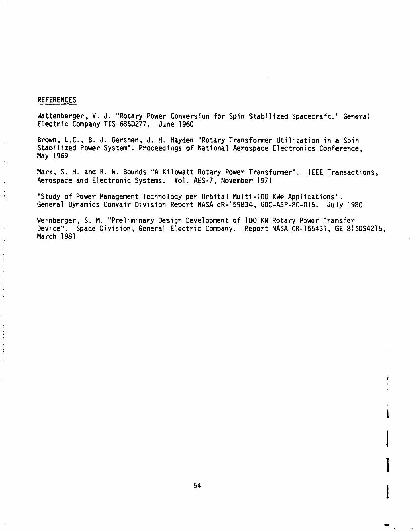
REFERENCES
Wattenberger, V . J. "Rotary Power Conversion fo r Spin Stabi 1 i zed Spacecraft." General E l e c t r i c Company TIS 68SD277. June 1960
Brown, L.C., B. J. Gershen, J. H. Hayden "Rotary Transformer U t i l i z a t i o n i n a Spin Stabi 1 i zed Power System". Proceedings of Nat ional Aerospace E lec t ron ics Conference, May 1969
Marx, S. H. and R. W. Bounds "A K i lowat t Rotary Power Transformer". I E E E Transactions, Aerospace and E lec t ron ic Systems. Vol. AES-7, November 1971
"Study o f Power Management Technology per O r b i t a l Mul t i -100 KWe Appl icat ions" . General Dynamics Convair D i v i s ion Report NASA eR-159834, GDC-ASP-80-015. Ju l y 1980
Weinberger, S. M. "Pre l iminary Design Development of 100 KW Rotary Power Transfer Device". Space D iv is ion , General E l e c t r i c Company. Report NASA CR- 165431 , GE 81 SDS4215, March 1981