Embed Size (px)
Citation preview

Preface
Only through the dedicated work of the members of the QMS has the available GDT-Data record
become possible. Everyone who wants to profit from the results is the called upon to contribute and also
take part in the consensus work.
Unfortunately, in the past defective and uncertified versions of GDT interfaces appeared under the
disguise of "GDT-Interface", which threaten the objective of standardized data transfers between
systems and ultimately undermine the efforts of the QMS for quality standards.
Therefore, we have decided first of all to list the defective implementations and their publishers on the
black board for members and thus out them for starters within the QMS. This action is accompanied by
a letter of the QMS board of directors to the responsible firma, to subject standard and adapt the
software. Otherwise these are requested not to use the name "GDT-Interface" anymore.
Hence: Become a member, contribute and get certified!!
GDT V 2.1 (5/01) Page 1 / 41

QMS Qualitätsring Medizinische Software(= Quality Associocation for Medical Software)
Connecting Medical Measuring Instruments(GDT - Gerätedaten-Träger (= Device Data Carrier))
Interface Description for
system-independent Data Transfer
between
electronic Data Processing Systems in Surgeries
and Measuring Instruments
Version 2.1 (5/2001)
Qualitätsring Medizinische Softwarec/o Antje KochConcordiastrasse 1050169 Kerpen
GDT V 2.1 (5/01) Page 2 / 41

Table of Contents
1. Introduction 4
1.1 General Information 4
1.2 Glossary of Terms 4
1.3 Communication 5
1.4 Labelling of Interface Properties 6
1.4.1 General Information 6
1.4.2 Minimum Requirements for an EDP system / DEVICE 6
1.4.3 EDP system labels 6
1.4.4 DEVICE labels 7
1.4.5 EDP system/DEVICE Sample Combinations 7
2. Interface Description 8
2.1 Component Identification (GDT-ID) 8
2.2 Character set 8
2.3 Communication via file 8
2.3.1 File names 8
2.3.2 Directory 9
2.4 Communication via Serial Interface 10
2.4.1 Hardware 10
2.4.2 Communication process 10
2.5 Sample Procedures 11
2.6 Annotated Sample Files 14
2.6.1 BDT Line Syntax 14
2.6.2 Sample File ”Root Data Transfer” 14
2.6.3 Sample File ”Test Data Transfer” 15
3. Set table 16
3.1 Set Type Definition 6300: Root Data Request 17
3.2 Set Type Definition 6301: Root Data Transfer 18
3.3 Set Type Definition 6302: New Test Request 19
3.4 Set Type Definition 6310: Test Data Transfer 20
3.5 Set Type Definition 6311: Test Data Display 22
4. Field Table (extension) 23
GDT V 2.1 (5/01) Page 3 / 41

5. Rules Table (extension) 25
6. Appendixes 26
6.1 Appendix A: Block Format for Serial Data Transfer with Samples 26
6.2 Appendix B: The device and method-specific Field "8402" 31
6.3 Appendix C: C-Program for Calculating CRC-16 36
6.4 Appendix D: Borland-Pascal 7. 0 Program for Calculating CRC-16 37
GDT V 2.1 (5/01) Page 4 / 41

1. Introduction
1.1 General Information
The available Interface Description has been compiled by QMS (Qualitätsring Medizinische Software) to
define a standardized interface between electronic Data Processing Systems in Surgeries and medical
measuring instruments.
The interface (Geräte-Daten-Träger – GDT = Device Data Carrier) is therefore designed to be device-
manufacturer- and section neutral. It can be used by standalone devices as well as PC supported measuring
devices. If direct communication, as discussed in this document, is technically impossible (for example with
older standalone devices using a manufacturer-specific interface), a suitable GDT-driver program should be
provided by the manufacturer.
The new version should evolve into a voluntary standard for Data Processing Systems in Surgeries and device
manufacturer. The certification takes place through the QMS-working committee GDT. (The interface
description is taken over through the central institute as addition to the BDT set description)
Further development of this interface will aim at the implementation of ”PLUG and PLAY” solutions for
linking medical devices with electronic data processing systems used in surgeries in order to keep installation
efforts to a minimum.
1.2 Glossary of terms
Throughout this interface description, the following terms are used:
GDT = Geräte-Daten-Träger (= Device Data Carrier, interface name compliant with BDT, LDT,
ADT)
DEVICE = medical device (or associated driver program),
standalone unit oder PC based measuring instrument
EDP SYSTEM = electronic data processing systems used in surgeries
COMPONENT = each party to data transfer, EDP or DEVICE
SERVER = COMPONENT that waits for external queries and commands and that is capable of
processing them (a PC network “Server” answers workstation queries only)
CLIENT = a COMPONENT that issues queries and commands
The terms CLIENT / SERVER are used only to describe the send / receive relationship and are not synonym
GDT V 2.1 (5/01) Page 5 / 41

with EDP system and DEVICE.
During installation it has to be decided which component should serve as SERVER and which as CLIENT to
avoid conflicts. As the actual purpose of linking devices is the transfer of test data, at least one EDP should
work as SERVER (processing of test data) and one DEVICE should at least act as CLIENT (sending of test
data) (see 1.4).
1.3 Communication
Generally, there are three different mechanisms for data communication:
• File Interface
DEVICE and EDP system communicate via files that are created with a certain file name and in a certain
directory, see below.
• Serial Interface
The attached DEVICE (or driver) communicates with the EDP system via a serail interface.
• Program-to-Program Interface
DEVICE and EDP system support program-to-program interfaces (for example Clipboard, DDE, OLE,
UNIX-Pipes, etc.)
This version of the interface description is limited to communication via serial oder file interfaces as of yet. An
extension to include program-to-program interfaces is planned. As all data is transferred as BDT data sets, the
appropriate data format depends on the method of communication used. (BDT = Büro- und Datentechnik =
Office and Data technology)
GDT V 2.1 (5/01) Page 6 / 41

1.4 Labelling of Interface Properties1.4.1 General Information
In order to uniquely define the technical description of the interfacing capability for the different
COMPONENTS, a special label is used which is defined differently for EDP systems and DEVICES.
In order to determine wether an EDP system can communicate with a DEVICE, you only need to check their
interface labels. Communication is possible if at least one transfer method (serial or file) and at least one
SERVER-/CLIENT information matches:
The technical documentation of a GDT-capable DEVICE or EDP system must therefore include the relevant
information of the type of GDT used.
1.4.2 Minimum Requirements for an EDP system and a DEVICE
The EDP system should at least be able to act as SERVER, i.e. it must be capable of replying to set type 6300
with set type 6301 and of processing set type 6310.
The DEVICE must at least be able to act as CLIENT, i.e. it must be capable of sending set type 6310.
1.4.3 Kennzeichnung für EDV
GDT-<xx>-<nn> <xx> = S serial data transfer in accordance with GDT is supported
= D data transfer via files in accordance with GDT is supported
= SD both methods are supported
<nn> = 10 EDP can act as SERVER
= 01 EDP can act as CLIENT
= 11 EDP can act as both, SERVER or CLIENT
Example: GDT-S-10 / GDT-D-11 (EDP system can act serially only as SERVER,
however via file it can be both, SERVER and CLIENT)
GDT V 2.1 (5/01) Page 7 / 41

1.4.4 DEVICE Labels
GDT-<xx>-<nn> <xx> = S serial data transfer in accordance with GDT is supported
= D data transfer via files in accordance with GDT is supported
= SD both methods are supported
<nn> = 01 DEVICE can act as SERVER
= 10 DEVICE can act as CLIENT
= 11 DEVICE can act as both, SERVER or CLIENT
Examplel: GDT-D-10 (DEVICE can act as CLIENT via file only)
1.4.5 EDP system/ DEVICE Sample Combinations
The following are examples of components that can communicate with each other:
EDP DEVICE
GDT-S-11 GDT-SD-01
GDT-D-10 GDT-D-11
GDT-SD-01 GDT-S-01
The following are examples of components that can not communicate with each other:
EDP DEVICE
GDT-S-11 GDT-D-11
GDT-SD-10 GDT-S-01
GDT V 2.1 (5/01) Page 8 / 41

2. Interface Description
2.1 Component Identification (GDT-ID)
The GDT-ID serves as clear indentification of the components that are part of the communication and is
defined during installation.
The ID made up of a total of 8 characters which are assigned in a manufacturer and device specific way. As all
information is assigned using these IDs, it is essential that all IDs are unique, especially in the case of mulitple
DEVICES (for example 2 ECG plotters form the same manufacturer).
2.2 Character Set
The character set allowed within BDT fields is the IBM 8 bit character set (Codepage 437) with characters >
20hex (32 dez.).
More character sets may be supported in addition. The topically used character set is defined in field label
9206.
2.3 Communication via File
2.3.1 File Names
Data are transferred via a BDT- compliant file, the name of which must be defined uniquely during installation.
The file name syntax is defined as follows:
<receiver-short name><sender-short name > . <incremental number>
(for example EDV2GER.005)
or
<receiver-short name><sender-short name > . GDT
(for example EDV2GER.GDT)
The file name consists of a maximum of 4 Characters as short name to indicate the receiver and a maximum of
4 characters for the sender of the file (see above).
The file name extension is a three-digit, incrementally increasing number that is continuously assigned to
GDT V 2.1 (5/01) Page 9 / 41

certain file names. The file count starts with consecutive extensions with .001 (leading zeros). This ensures
that you can send multiple files, for example from a DEVICE to an EDP system.
If a system supports one fixed file name only, the extension for this file must be . GDT (for example
EDV1EKG1.GDT).
During installation, you choose a device-specific setting for the file type (fixed or progressive) you want to use.
Files are generated by the sender with the extensions increasing incrementally.
If a file with the extension .GDT still exists (i.e. its receiver has not read it yet), the sender should not overwrite
it (loss of data).
The handling through the receiver durch den Empfänger has to be carried out sorted by date/time (FIFO). After
reading, the files have to be deleted by the reciever.
To avoid communication problems, the sender should write the communication data without a break. Is a delay
necessary, a new file has to be generated for muß eine neue Datei with consecutive extension.
Also, there can be several successive GDT-sets within a file. In one file, several different types of sets can be
used by different patients.
2.3.2 Directory
During installation, you choose the drive and the directory used to store the GDT communication files. This
information is also needed during device-/EDP configuration.
GDT V 2.1 (5/01) Page 10 / 41

2.4 Communication via serial Interface
2.4.1 Hardware
The minimum requirement for communication is a three-phase serial cable (RxD, TxD, GND) without
hardware-handshake.
Optionally, other interface signals (RTS, CTS, DTR etc.) may be supported.
Interface parameters (minimum requirement)
Baud Rate = 2400 Baud (different values optional)
Data Bits = 8Parity = noneStart Bits = 1Stop Bits = 1
Connection cable (minimum requirement)
(Pin assignment for 25-pin ports/values for 9-pin ports provided in brackets)
TxD Pin 2 (3) ──────────────── (2) Pin 3 RxD (Receive Data)
RxD Pin 3 (2) ──────────────── (3) Pin 2 TxD (Transmit Data)
GND Pin 7 (5) ──────────────── (5) Pin 7 GND (Signal Ground)
RTS Pin 4 (7) ─── ─── (7) Pin 4 RTS (Request To Send)
CTS Pin 5 (8) ─── ──── (8) Pin 5 CTS (Clear To Send)
DTR Pin 20 (4) ─── ─── (4) Pin 20 DTR (Data Terminal Ready)
DSR Pin 6 (6) ─── ─── (6) Pin 6 DSR (Data Set Ready)
2.4.2 Communication Process
Defined labels for BDT data sets and fields (with special labels) are used as data fields. All BDT data are
transmitted in a fixed block format (see APPENDIX A). The protocol contains the definition of a software
handshake so that an additional, external handshake prodecure (XON-XOFF) is not necessary.
In order to maintain compatibility, sentence and line lenghts for the transmitted BDT files are calculated as
CR/LF (as defined in BDT); however, instead of these two characters, only one field separator (1CH) is sent
because CR is defined as a separator for serial transfer (see example in APPENDIX A).
GDT V 2.1 (5/01) Page 11 / 41

2.5 Sample Procedures
The examples are based on the following surgery scenario with the components listed.
The surgery works with the software "PRAX_EDV" (GDT-SD-11). Three DEVICES are connected to this
program:
(1) A phoropter (opthalmic test device, test glasses with changeabel lenses) (GDT-S-10), connected via
serial cable, which requires you to press a button to send test data to EDP (no root data management of its own)
(EDP is SERVER / DEVICE is CLIENT).
(2) A PC based ECG plotter (GDT-D-01) that provides ist own root data management. It is called from the
index card (EDP is CLIENT / DEVICE is SERVER). A PC based program used to start the ECG named
ECG.BAT is stored in C:\REST_ECG.
(3) A spirometer (GDT-D-10) that provides its own root data management. It is controlled by DEVICE and
communicates with an EDP system (EDP system is SERVER / DEVICE is CLIENT).
The spirometer program is called D:\LUFU SPIRO.exe.
1. Communicatio between EDP system and phoropter (not root data management)
EDP system = SERVER DEVICE = CLIENT
Measurement is taken by phoropter
At the push of a button on the DEVICE, test data are sent as
data set type 6310 via serial cable
EDP receives data and assigns them to
the current patient
GDT V 2.1 (5/01) Page 12 / 41

2. Communication between EDP system and ECG plotter
EDP system = CLIENT DEVICE = SERVER
Patient to be examined it selected in EDP
system
EDP system creates file named F: \ GDT \ EKG1EDV1.001 using set
type 6302 to request another test (ECG in resting position:
8402=EKG01)
Switching to device software by calling the ECG.BAT directory
in C:\REST.ECG
DEVICE reads and deletes filei F: \ GDT \ EKG1EDV1.001
An ECG in resting position is taken for the current patient
DEVICE creates file names F: \ GDT \ EDV1EKG1.001 using set
type 6310 to transmit test results.
Closing of program and switching to EDP system.
EDP system reads and deletes filei F: \ GDT \ EDV1EKG1.001
EDP system assigns data to current patient
GDT V 2.1 (5/01) Page 13 / 41

3. Communication between EDP system and spirometer
EDP = SERVER DEVICE = CLIENT
Patient to be examined is available in EDP system
Patient is requested at the push of a button:
DEVICE creates file named F: \ GDT \ EDV_LUFU.001 using set
type 6300 to request current patient
EDP system reads and deletes file F: \ GDT \ EDV_LUFU.001
EDP system creates file named F: \ GDT \ LUFU_EDV.001 using set
type 6301 to transmit curent root data set
DEVICE read and deletes file F: \ GDT \ LUFU_EDV.001
Spirometer measurements are taken for the current patient
DEVICE creates file namedi F: \ GDT \ EDV_LUFU.002 using set
type 6310 to transmit test results
For the same patient, another spirometer test is carried out
DEVICE creates file named F: \ GDT \ EDV_LUFU.003 using set
type 6310 to transmit test results
EDP system read and deletes files
F: \ GDT \ EDV_LUFU.002 und EDV_LUFU.003,
EDP system assigns data to the current patient
GDT V 2.1 (5/01) Page 14 / 41

2.6 Annotated Sample Files
2.6.1 BDT Line Syntax:
0163101Schmidt<CR><LF>
Line length incl. CR LF
Line contents field label
BDT field contents
End of line (CR LF / 0D 0A hex)
2.6.2 Sample File ”Root Data Transfer”
01380006301 ↓ ↵ ; Set type ”Root Data Transfer”
014810000173 ↓ ↵ ; File Size
0178315EKG_TYP1 ↓ ↵ ; Receiver GDT-ID (for example ECP plotter)
0178316PRAX_EDP ↓ ↵ ; Sender GDT-ID
014921802.00 ↓ ↵ ; Version Number GDT
014300002345 ↓ ↵ ; Patient Number
0193101Samplesmith ↓ ↵ ; Surname
0143102John ↓ ↵ ; First Name
017310301101945 ↓ ↵ ; Date of Birth
01031101 ↓ ↵ ; Sex (1=male)
0123622178 ↓ ↵ ; Height
0123623079 ↓ ↵ ; Weight
↓ ↵ = CR und LF (0D 0A hex)
Every syntax line has to be ended with CR and LF (0D 0A hex).
GDT V 2.1 (5/01) Page 15 / 41

2.6.3 Sample File ”Test Data Transfer”
01380006310 ↓ ↵ ; Set Type
014810000962 ↓ ↵ ; File Size
0198315PRAX_EDP ↓ ↵ ; Receiver GDT-ID
0148316LZBD_SYS ↓ ↵ ; Sender GDT-ID
014921802.00 ↓ ↵ ; Version Number GDT
014300002345 ↓ ↵ ; Patient Number
0193101Samplesmith ↓ ↵ ; Surname
0143102John ↓ ↵ ; First Name
017310301101945 ↓ ↵ ; Date of Birth
01031101 ↓ ↵ ; Sex (1=male)
0123622178 ↓ ↵ ; Height
0123632079 ↓ ↵ ; Weight
0158402BDM01 ↓ ↵ ; Test: 24h-Blood Pressure
017620023101998 ↓ ↵ ; Test Date
0346220This∨is∨a∨two-line ↓ ↵ ; Result 1. Zeile
0416220result∨of∨24h-blood∨pressure∨test ↓ ↵ ; Result 2. Zeile
0566227Comments∨ to∨ a∨ long-term-blood∨ pressure∨ test ↓ ↵ ; Comment
0506228Summary∨ 24∨ h∨ blood∨ pressure∨ test ↓ ↵ ; formatted results text
0606228-------------------------------------------------- ↓ ↵
0606228∨ ∨ ∨ ∨ ∨ ∨ ∨ ∨ ∨ ∨ day∨ phase∨ ∨ ∨ ∨ ∨ ∨ ∨ night∨ phase ∨ ∨ ∨ percent∨ decrease ↓ ↵
0596228∨ ∨ ∨ ∨ ∨ ∨ ∨ ∨ 06:00-22:00∨ ∨ ∨ ∨ 22:00-06:00∨ ∨ ∨ ∨ day/night ↓ ↵
0606228Ps[mmHg]∨ ∨ ∨ ∨ ∨ 143∨ ∨ ∨ ∨ ∨ ∨ ∨ ∨ ∨ ∨ ∨ ∨ ∨ ∨ 134∨ ∨ ∨ ∨ ∨ ∨ ∨ ∨ ∨ ∨ ∨ ∨ ∨ -6∨ % ↓ ↵
0606228Pd[mmHg]∨ ∨ ∨ ∨ ∨ ∨ 92∨ ∨ ∨ ∨ ∨ ∨ ∨ ∨ ∨ ∨ ∨ ∨ ∨ ∨ ∨ 92∨ ∨ ∨ ∨ ∨ ∨ ∨ ∨ ∨ ∨ ∨ ∨ ∨ ∨ 0∨ % ↓ ↵
0606228HF[P/min]∨ ∨ ∨ ∨ ∨ ∨ 71∨ ∨ ∨ ∨ ∨ ∨ ∨ ∨ ∨ ∨ ∨ ∨ ∨ ∨ ∨ 70∨ ∨ ∨ ∨ ∨ ∨ ∨ ∨ ∨ ∨ ∨ ∨ ∨ -1∨ % ↓ ↵
0178410SYSMXTG ↓ ↵ ; Test-ID (manufacturer-spec.)
0298411Systole∨ max∨ day∨ phase ↓ ↵ ; Testname
0128420142 ↓ ↵ ; Value
0138421mmHg ↓ ↵ ; Unit
017843223101998 ↓ ↵ ; reading date
0158439163400 ↓ ↵ ; reading time
0128462140 ↓ ↵ ; upper threshold
0178410SYSMNTG ↓ ↵ ; next Test-ID
0298411Systole∨ min∨ day∨ phase ↓ ↵ ; Test name
0128420112 ↓ ↵ ; Value
0138421mmHg ↓ ↵ ; Unit
017843224101998 ↓ ↵ ; reading date
0158439031200 ↓ ↵ ; reading time
∨ = space ( 20 hex / 32 dez ) ↓ ↵ = CR and LF ( 0D 0A hex )
GDT V 2.1 (5/01) Page 16 / 41

3. Set Table
Below, you find a decription of sets 6300, 6301, 6302, 6310, and 6311 that have been defined for
linking medical devices.
Each set starts with the field "8000" which contains its sentence label.
However, sentence type 6300 „Root Data Request“ requires a sentence type 6301 „Root Data
Transfer“ reply.
All remaining sentence types (6301, 6302, 6310, 6311) may be transmitted at any time and do not
require a reply.
Generally, the direction of communication is a follows:
6300: MG PCS
6301: PCS MG
6302: PCS MG
6310: MG PCS
6311: PCS MG
MG = Medizingerät (medical device)
PCS = Praxiscomputersystem (surgery computer system)
GDT V 2.1 (5/01) Page 17 / 41

3.1 Set Type Definition: Root Data Request "6300"
SA 6300 Field- Instance Description necessary Condition
Changes label 1 2 3 4 Fieldcontents M/K Prerequisites
8000 1 Sentence ID M Root Data Request Set Type8100 1 Sentence length M Length of this Set
8315 1 Receiver GDT - ID K8316 1 Sender GDT - ID K9206 1 Set Type used K 1=7Bit, 2=IBM(Standard) CP 437, 3=ISO8859-1(ANSI) CP12529218 1 Version GDT M 02.10
3000 1 Patient Number / Patient Label M If a DEVICE cannot transmit the patient number, a value of 0 should be sent in order to request patient data of the current patient.
GDT V 2.1 (5/00) Seite 18 / 44

3.2 Set Type Definition: Root Data Transfer "6301"
SA 6301 Field- Instances Description necessary Condition
Changes label 1 2 3 4 Field Contents M/K Prerequisites
8000 1 Sentence ID M Root Data Transfer Set Type8100 1 Sentence Length M Length of this Set
8315 1 Receiver GDT - ID K8316 1 Sender GDT - ID K9206 1 Set Type used K 1=7Bit, 2=IBM(Standard) CP 437, 3=ISO8859-1(ANSI) CP 12529218 1 Version GDT M 02.10
3000 1 Patient Number / Patient Label M
3100 1 Prefix / Additional Name of Patient K e.g. Lord3101 1 Name of Patient M3102 1 Patient First Name M3103 1 Patient Birth Date M DDMMYYY3104 1 Patient Title K3105 1 Patient Insurance Number K3106 1 Patient Residence K Zip Code3107 1 Patient Street K Street and Number3108 1 Insurance Status K 1=Member, 3=Family Member of Insured, 5=Retired3110 1 Patient Sex K 1=Male, 2=female3622 1 Patient Height K3623 1 Patient Weight K3628 1 First Language of Patient K
GDT V 2.1 (5/00) Seite 19 / 44

3.3 Set Type Definition: New Test Request "6302"
SA 6302 Field- Instances Description necessary Condition
Changes label 1 2 3 4 Field Contents M/K Prerequisites
8000 1 Sentence ID M New Data Request Set Type8100 1 Sentence Length M Length of this Sentence
8315 1 Receiver GDT - ID K8316 1 Sender GDT - ID K9206 1 Set Type used K 1=7Bit, 2=IBM(Standard) CP 437, 3=ISO8859-1(ANSI) CP 12529218 1 Version GDT M 02.100102 1 The resposible one for the software K e.g. firm0103 1 Software K Name of software0132 1 Release state of software K Software versionnumber
3000 1 Patient Number / Patient Label M
3100 1 Prefix / Additional Name of Patient K e.g. Lord3101 1 Name of Patient M3102 1 Patient First Name M3103 1 Patient Birth Date M DDMMYYYY3104 1 Patient Title K3105 1 Patient Insurance Number K3106 1 Patient Residence K Zip Code3107 1 Patient Street K Street and Number3108 1 Insurance Status K 1=Member, 3=Family Member of Insured, 5=Retired3110 1 Patient Sex K 1=Male, 2=female3622 1 Patient Height K3623 1 Patient Weight K3628 1 First Language of Patient K
8402 1 Device and method specific field K Requested Test Type, e.g.. EKG01(see Appendix B)
8410 1 Test-ID K
GDT V 2.1 (5/00) Seite 20 / 44

3.4 Set Type Definition: Test Data Transfer "6310"
SA 6310 Field- Instances Description necessary Condition
Changes label 1 2 3 4 Field Contents M/K Prerequisites
8000 1 Sentence ID M Transfer Data Set Type8100 1 Sentence Length M Length of this Sentence
8315 1 Receiver GDT - ID K8316 1 Sender GDT - ID K9206 1 Set Type used K 1=7Bit, 2=IBM(Standard) CP 437, 3=ISO8859-1(ANSI) CP 12529218 1 Version GDT M 02.100102 1 The responsible one for the software K e.g. firm0103 1 Software K Name of software0132 1 Release state of software K Software versionnumber
3000 1 Patient Number / Patient Label M If a DEVICE cannot transmit the patient number, a value of 0 should be sent in order to request patient data of the current patient.
3100 1 Prefix / Additional Name of Patient K e.g. Lord3101 1 Name of Patient K3102 1 Patient First Name K3103 1 Patient Birth Date K DDMMYYYY3104 1 Patient Title K3105 1 Patient Insurance Number K3106 1 Patient Residence K PLZ ORT3107 1 Patient Street K Straße und Hausnummer3108 1 Insurance Status K3110 1 Patient Sex K 1=Member, 3=Family Member of Insured, 5=Retired3622 1 Patient Height K 1=Male, 2=female3623 1 Patient Weight K3628 1 First Language of Patient K8402 1 Device and method specific field M Requested Test Type, e.g.. EKG01
(see Appendix B)
GDT V 2.1 (5/00) Seite 21 / 44

3.4 Set Type Definition: Test Data Transfer "6310"
SA 6310 Field- Instances Description necessary Condition
Changes label 1 2 3 4 Field Contents M/K Prerequisites
6200 1 Day treatment data were saved K DDMMYYYY Test Date6201 1 Time treatment data were saved K HHMMSS; time (6 digits) of indicated test6205 n Current Diagnosis K6220 n Results K6221 n Third Party Results K for example results that were automatically generated by the
device6227 n Comments K6226 n Number of following Lines of the Identifier 6228 K Herewith can the GDT length restriction be bypassed when
transferring 6228. If, for example, a value of 2 is transferred, the following two lines 6228 form one complete line which has to be assembled by the receiver.
6228 n Result Table Text, formatted K any result text formatted by the device6302 n Attribute for (Archive-)file K Attribute to classify the Data6303 1 File format m If field 6302 exists Description of file format (e.g. PDF)6304 1 Information about the Content of file m If field 6302 exists Description of what is located under the following adress(es)
(WWW adress or UNC path)e.g. Protocols, Items/values of the Test Date
6305 1 Reference to the file m If field 6302 exists Uniform Resource Locator (WWW-address or UNC-Path)e.g. \\FS1\TEST\BILD1.PDF
6330, 6332, 6334, ...,6398
n Name of open Category K Even and the following uneven identifier build a value pair respectively
6331,6333,6335,...,6399
1 Content of open Category m in case previous identifier „ Name of open Category“ exists
8410 n Test-ID m 20 Signs alnumif field(s) > = 8411
< = 8480
Header to transfer single Measurement value groups
8411 1 Test Name K8428 1 Test Material ID K8429 1 Test Material Index K8430 1 Test Material Label K8431 n Test Material Specification K8437 1 Unit(s) for Data Stream m if field(s) 8438 <> (blank) for example. Hz, dBA8438 n Data Stream K for example (50,-30),(100,-20),(150,-22),(200,-17),.....etc8418 1 Test Status K B = already reported, K = corrected value or missing8420 1 Result Value K8421 1 Unit m if field(s) 8420, 8461, 8462 <>
(blank)
GDT V 2.1 (5/00) Seite 22 / 44

8432 1 Reading Date K DDMMYYYY ; Single Reading Date
8439 1 Reading Time K HHMMSS ; Time (6 digits) of Single Reading8460 1 Standard Value Text K8461 1 lower Threshold Standard Value K Value is transm. in Unit 8421 8462 1 upper Threshold Standard Value K Value is transm. in Unit 8421 8470 n Comments K Test Notes8480 n Results Text K8990 1 Signature K Name/Short Name of Person conducting the Test
GDT V 2.1 (5/00) Seite 23 / 44
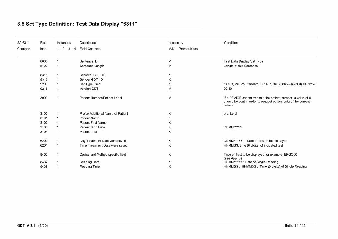
3.5 Set Type Definition: Test Data Display "6311"
SA 6311 Field- Instances Description necessary Condition
Changes label 1 2 3 4 Field Contents M/K Prerequisites
8000 1 Sentence ID M Test Data Display Set Type8100 1 Sentence Length M Length of this Sentence
8315 1 Reciever GDT ID K8316 1 Sender GDT ID K9206 1 Set Type used K 1=7Bit, 2=IBM(Standard) CP 437, 3=ISO8859-1(ANSI) CP 12529218 1 Version GDT M 02.10
3000 1 Patient Number/Patient Label M If a DEVICE cannot transmit the patient number, a value of 0 should be sent in order to request patient data of the current patient.
3100 1 Prefix/ Additional Name of Patient K e.g. Lord3101 1 Patient Name K3102 1 Patient First Name K3103 1 Patient Birth Date K DDMMYYYY3104 1 Patient Title K
6200 1 Day Treatment Data were saved K DDMMYYYY Date of Test to be displayed6201 1 Time Treatment Data were saved K HHMMSS; time (6 digits) of indicated test
8402 1 Device and Method specific field K Type of Test to be displayed for example ERGO00(see App. B)
8432 1 Reading Date K DDMMYYYY ; Date of Single Reading8439 1 Reading Time K HHMMSS ; HHMMSS ; Time (6 digits) of Single Reading
GDT V 2.1 (5/00) Seite 24 / 44

4. Field Table
This table shows the field labels used in sets 6300, 6301, 6302, 6310, and 6311.
* Changes to the field table are indicated on the left as follows:
*L = change of length
*N = new field; in Version 1 this denotes a new field label which in accordance with the central institute
(Zentralinstitut) was assigned especially to GDT
*R = change of rule; in Version 1 this denotes a rule number for format/content verification not provided by
the KBV Verification Module
*Nx.x = new field from Version x.x
FK Name Length Type Rule Example
*N2.1 0102 The responsible one for the software
<=60 alnum Firm xxx
*N2.1 0103 Software <=60 alnum PraxisMed
*N2.1 0132 Release state of software <=60 alnum Version 4.30b
3000 Patient Number / Patient Label <=10 alnum 123456
3100 Prefix / Additional Name of
Patient
<=15 alnum Lord
3101 Patient Name <=28 alnum Smith
3102 Patient First Name <=28 alnum Mary
3103 Patient Date of Birth 8 datum 020/304 12041946
3104 Patient Title <=15 alnum Dr.
3105 Social Security Number of Patient <=12 alnum 123456M789
3106 Patient Residence <=30 alnum 50859 Köln
3107 Patient Street <=28 alnum Holzweg 106
3108 Insurance Status MFR 1 num 116 3
3110 Patient Sex 1 num 112 1
3622 Patient Height in cm var float 175.50
3623 Patient Weight in kg var float 90.50
3628 First Language of Patient <=60 alnum english
6200 Day treatment data were saved 8 date 008 12031993
6201 Time treatment data were saved 6 time 090 HHMMSS 132201
6205 Current Diagnosis <=60 alnum Diabetes
6220 Results <=60 alnum high blood pressure
6221 Third Party Results <=60 alnum suspected obstruction
GDT V2.1 (5/00) Page 25 / 41
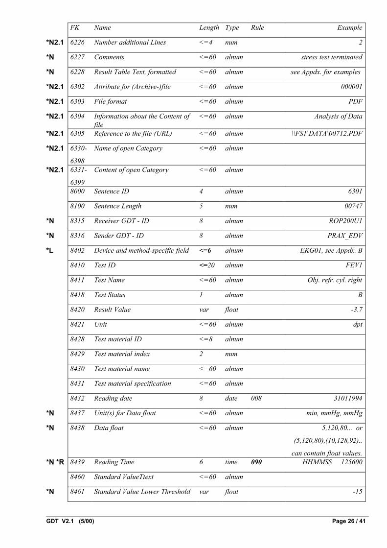
FK Name Length Type Rule Example
*N2.1 6226 Number additional Lines <=4 num 2
*N 6227 Comments <=60 alnum stress test terminated
*N 6228 Result Table Text, formatted <=60 alnum see Appdx. for examples
*N2.1 6302 Attribute for (Archive-)file <=60 alnum 000001
*N2.1 6303 File format <=60 alnum PDF
*N2.1 6304 Information about the Content of file
<=60 alnum Analysis of Data
*N2.1 6305 Reference to the file (URL) <=60 alnum \\FS1\DATA\00712.PDF
*N2.1 6330-
6398
Name of open Category <=60 alnum
*N2.1 6331-
6399
Content of open Category <=60 alnum
8000 Sentence ID 4 alnum 6301
8100 Sentence Length 5 num 00747
*N 8315 Receiver GDT - ID 8 alnum ROP200U1
*N 8316 Sender GDT - ID 8 alnum PRAX_EDV
*L 8402 Device and method-specific field <=6 alnum EKG01, see Appdx. B
8410 Test ID <=20 alnum FEV1
8411 Test Name <=60 alnum Obj. refr. cyl. right
8418 Test Status 1 alnum B
8420 Result Value var float -3.7
8421 Unit <=60 alnum dpt
8428 Test material ID <=8 alnum
8429 Test material index 2 num
8430 Test material name <=60 alnum
8431 Test material specification <=60 alnum
8432 Reading date 8 date 008 31011994
*N 8437 Unit(s) for Data float <=60 alnum min, mmHg, mmHg
*N 8438 Data float <=60 alnum 5,120,80... or
(5,120,80),(10,128,92)..
can contain float values.*N *R 8439 Reading Time 6 time 090 HHMMSS 125600
8460 Standard ValueTtext <=60 alnum
*N 8461 Standard Value Lower Threshold var float -15
GDT V2.1 (5/00) Page 26 / 41

FK Name Length Type Rule Example
*N 8462 Standard Value Upper Threshold var float 12
8470 Test Notes <=60 alnum
8480 Results Text <=60 alnum
8990 Signature <=60 alnum Dr. Cooper
*N2.1 9206 Set Type used 1 num 2
*N 9218 Version GDT 5 alnum 01.00 oder 02.00
datum = date format DDMMYYY
num = numeric, in case of fixed field length, the field nees to be filled with a leading zero
alnum = alphanumeric
float = floating-point number
GDT V2.1 (5/00) Page 27 / 41
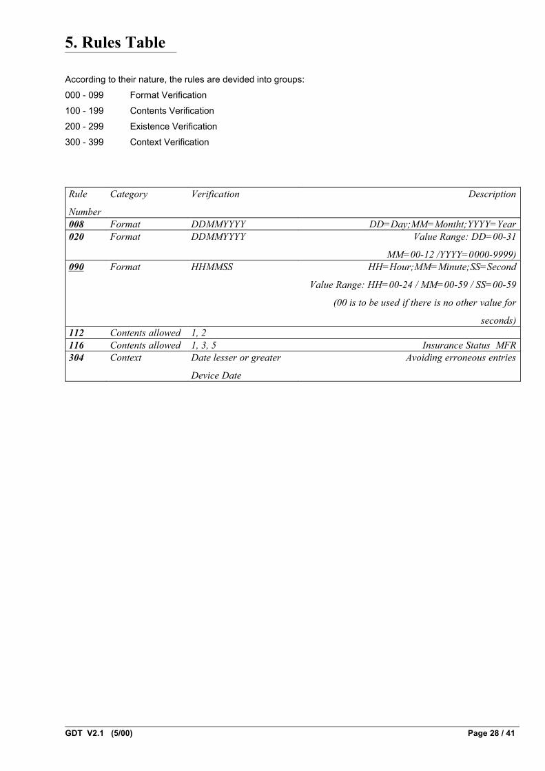
5. Rules Table
According to their nature, the rules are devided into groups:
000 - 099 Format Verification
100 - 199 Contents Verification
200 - 299 Existence Verification
300 - 399 Context Verification
Rule
Number
Category Verification Description
008 Format DDMMYYYY DD=Day;MM=Montht;YYYY=Year020 Format DDMMYYYY Value Range: DD=00-31
MM=00-12 /YYYY=0000-9999)090 Format HHMMSS HH=Hour;MM=Minute;SS=Second
Value Range: HH=00-24 / MM=00-59 / SS=00-59
(00 is to be used if there is no other value for
seconds)112 Contents allowed 1, 2116 Contents allowed 1, 3, 5 Insurance Status MFR304 Context Date lesser or greater
Device Date
Avoiding erroneous entries
GDT V2.1 (5/00) Page 28 / 41

6. Appendixes
6.1 Appendix A Block Format for Serial Data Transfer with Samples
6.1.1 Transfer Protokoll
A BDT file is transmitted in several blocks. Receipt of a block must be confirmed within 10 seconds by sending
an ACK (06h) followed by a 1 (31h) if the block is received correctly and completely, or followed by a 0 (30h)
if it was transmitted incorrectly.
6.1.2 Transmission Block
A transmission block has the following structure:
<Sending Sequence Count> <Label> [<Data Field>] <CRC-16> <CR>
6.1.3 Field Description
Sending Sequence Count
Length: 1 Byte.
The sending sequence count counts periodically from 1 (31h) to 9 (39h). If a transmission block has to
be re-sent due to incorrect transmission, the sending sequence count remains the same. A value of 0
(30h) is used for synchronization. This value is applied during the first transmission just after starting
and when a transmission error occurs.
Label
Length: 3 Bytes
The following labels are defined:
B00 Start of a BDT data transfer/first BDT data block
B01 BDT data block
B02 End of a BDT data transfer / last BDT data block
Data Field
Length: max. 128 Bytes
The actual BDT data are contained in the data field. Multiple BDT lines may be combined into a single
data field, or a single BDT line may be spread over multiple data fields. The character 1 Ch (Field
Separator FS) is used to separate two adjoining BDT lines. BDT sentence and line lengths are
calculated inclusive of CR/LF.
Apart from the field separator, no other ASCII character used in a data field may be less than 20h.
GDT V2.1 (5/00) Page 29 / 41
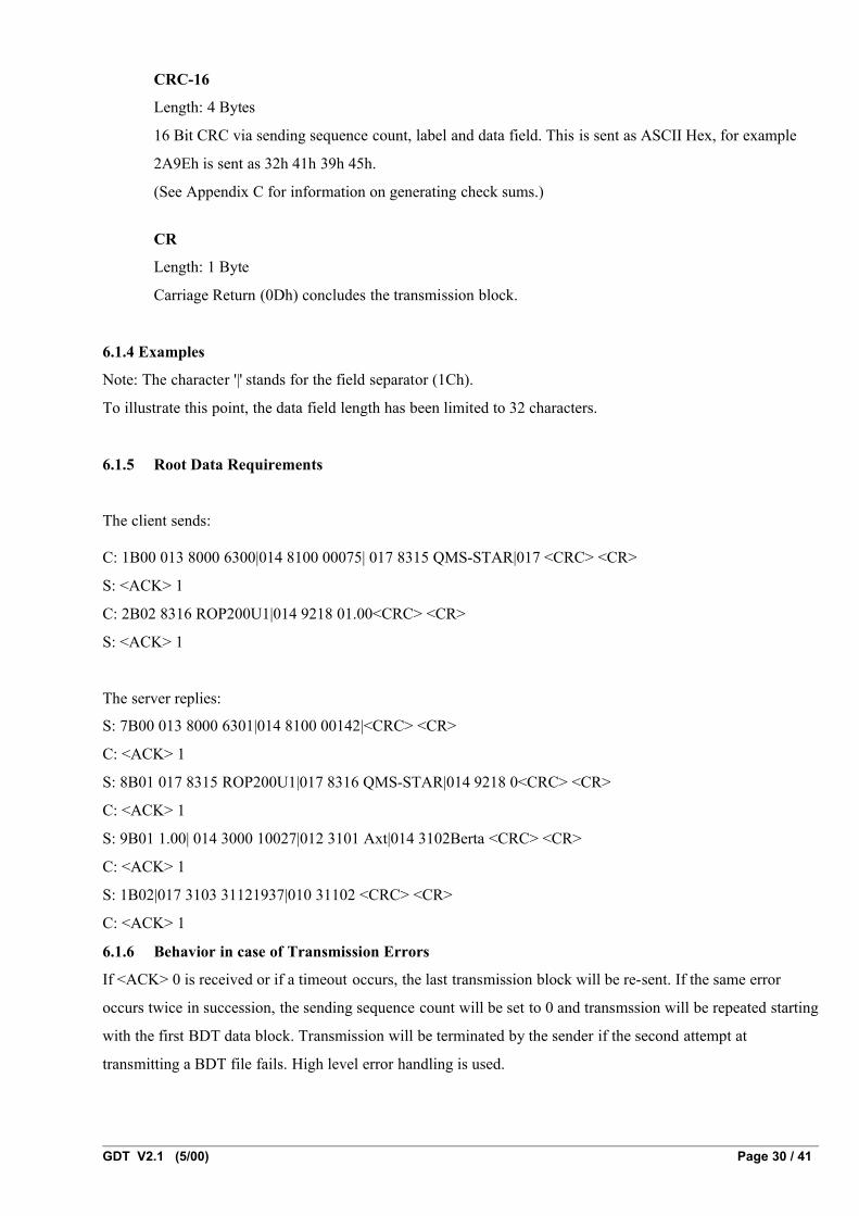
CRC-16
Length: 4 Bytes
16 Bit CRC via sending sequence count, label and data field. This is sent as ASCII Hex, for example
2A9Eh is sent as 32h 41h 39h 45h.
(See Appendix C for information on generating check sums.)
CR
Length: 1 Byte
Carriage Return (0Dh) concludes the transmission block.
6.1.4 Examples
Note: The character '|' stands for the field separator (1Ch).
To illustrate this point, the data field length has been limited to 32 characters.
6.1.5 Root Data Requirements
The client sends:
C: 1B00 013 8000 6300|014 8100 00075| 017 8315 QMS-STAR|017 <CRC> <CR>
S: <ACK> 1
C: 2B02 8316 ROP200U1|014 9218 01.00<CRC> <CR>
S: <ACK> 1
The server replies:
S: 7B00 013 8000 6301|014 8100 00142|<CRC> <CR>
C: <ACK> 1
S: 8B01 017 8315 ROP200U1|017 8316 QMS-STAR|014 9218 0<CRC> <CR>
C: <ACK> 1
S: 9B01 1.00| 014 3000 10027|012 3101 Axt|014 3102Berta <CRC> <CR>
C: <ACK> 1
S: 1B02|017 3103 31121937|010 31102 <CRC> <CR>
C: <ACK> 1
6.1.6 Behavior in case of Transmission Errors
If <ACK> 0 is received or if a timeout occurs, the last transmission block will be re-sent. If the same error
occurs twice in succession, the sending sequence count will be set to 0 and transmssion will be repeated starting
with the first BDT data block. Transmission will be terminated by the sender if the second attempt at
transmitting a BDT file fails. High level error handling is used.
GDT V2.1 (5/00) Page 30 / 41

6.1.7 Sample Transfers containing Transmission Errors
Transmission Block Repeat
C: 1B00 013 8000 6300|014 8100 00075|017 8315 QMS-STAR|017 <CRC> <CR>
S: <ACK> 1
C: 2B02 8316 ROP200U1|014 9218 01.00<CRC> <CR>
S: <ACK> 0 ; error occurred
C: 2B02 8316 ROP200U1|014 9218 01.00<CRC> <CR> ; re-sending block with sending sequence
count remaining the same (this example 2)
S: <ACK> 1 ; block is received correctly
Synchronisation upon Transmission Error
C: 1B00 013 8000 6300|014 8100 00075|017 8315 QMS-STAR|017 <CRC> <CR>
S: <ACK> 1
C: 2B02 8316 ROP200U1|014 9218 01.00<CRC> <CR>
S: <ACK> 0 ; error occurred
C: 2B02 8316 ROP200U1|014 9218 01.00<CRC> <CR>
S: <ACK> 0 ; error re-occurred
C: 0B00 013 8000 6300|014 8100 00075|017 8315QMS-STAR|017 <CRC> <CR>
; re-synchronization
; sequence count 0
S: <ACK> 1
C: 1B02 8316 ROP200U1|014 9218 01.00<CRC> <CR>
S: <ACK> 1
GDT V2.1 (5/00) Page 31 / 41

Transmission terminated upon Transmission Error
C: 1B00 013 8000 6300|014 8100 00075|017 8315 MEDISTAR|017 <CRC> <CR>
S: <ACK> 1
C: 2B02 8316 ROP200U1|014 9218 01.00<CRC> <CR>
S: <ACK> 0 ; error occurred
C: 2B02 8316 ROP200U1|014 9218 01.00<CRC> <CR>
S: <ACK> 0 ; error occurred
C: 0B00 013 8000 6300|014 8100 00075|017 8315 QMS-STAR|017 <CRC> <CR>
S: <ACK> 1
C: 2B02 8316 ROP200U1|014 9218 01.00<CRC> <CR>
S: <ACK> 0 ; error occurred
C: 2B02 8316 ROP200U1|014 9218 01.00<CRC> <CR>
S: <ACK> 0
Transmission terminated by sender. Receiver remains ready to receive.
Root Data Request Transmission Error
The following situation may cause both the client and the server to attempt to send a BDT file:
C: 1B00 013 8000 6300|014 8100 00075|017 8315 QMS-STAR|017 <CRC> <CR>
S: <ACK> 1
C: 2B02 8316 ROP200U1|014 9218 01.00<CRC> <CR>
S: [<ACK> 1] ; the server sends confirmation of file
receipt, which is not received by the
client
C: 2B02 8316 ROP200U1|014 9218 01.00<CRC> <CR> ; re-sending the same block
S: 7B00 013 8000 6301|014 8100 00142|<CRC> <CR> ; the server is already ending the first
block of the requested root data
C: 0B00 013 8000 6300|014 8100 00075|017 8315 QMS-STAR|017 <CRC> <CR>
; the client re-sends data using re-
synchronization
S: 7B00 013 8000 6301|013 8100 0141|<CRC> <CR> ; the server repeats the first block of root
data (ACK 1 from the client is missing)
C: 0B00 013 8000 6300|014 8100 00075|017 8315 QMS-STAR|017 <CRC> <CR>
; the client re-attempts synchronization
S: 0B00 013 8000 6301|014 8100 00141|<CRC> <CR> ; the server re-sends data using re-
synchronization
S: 0B00 013 8000 6301|014 8100 00141|<CRC> <CR> ; the server re-attempts
GDT V2.1 (5/00) Page 32 / 41

synchronization
This transmission is terminated by both the server and the client upon timeout („wait for ACK“)
(vgl. 6.1.6).
GDT V2.1 (5/00) Page 33 / 41

6.2 Appendix B The device and method-specific field "8402"
Field 8402 has been re-defined as follows as part of a BDT review (medical devices connection and data
transfer):
Field Label: 8402
Name: device and method-specific field
Function: This field is used to group the data to be transmitted.
Type: The previous type, 2 (alnum) has been expanded to 1 - 6 (alnum)..
Rule: The field contents are made up of text containing up to 4 characters to acts as a group label
followed by two-digit numbering from 00 through 99 (for example LUFU09), where 00 is
always reserved for use as a field for a non-specified test within that group. The group
label ALLG (often ALLG00) is used for tests that cannot be classified more precisely.
The field contents list is dynamic and is managed centrally by the ZI.
The groups and field contents listed below therefore represent a provisional list that may be expanded as
needed.
Unlike label 8402, test IDs (lable 8410) may be assigned in a manufacturer-specific way (see Appendix B of
BDT 2/94).
GDT V2.1 (5/00) Page 34 / 41
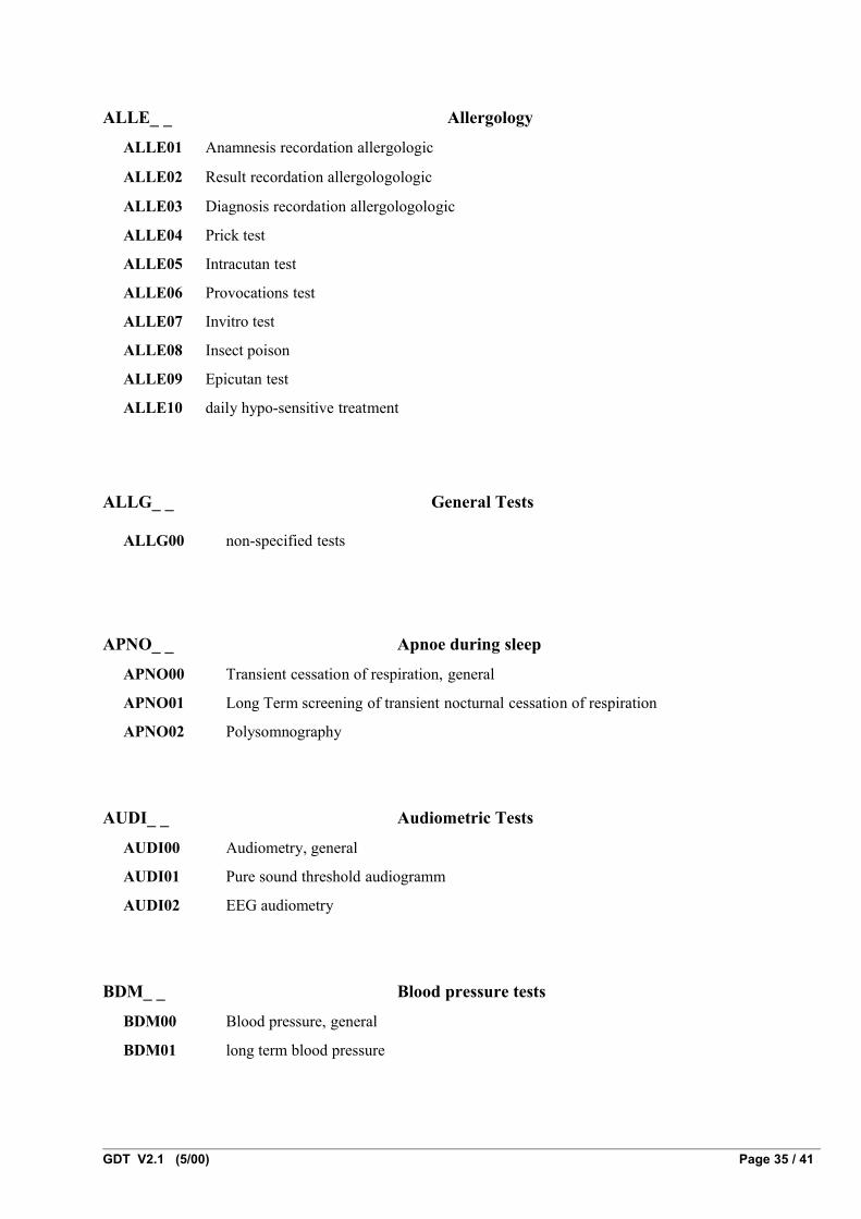
ALLE_ _ Allergology
ALLE01 Anamnesis recordation allergologic
ALLE02 Result recordation allergologologic
ALLE03 Diagnosis recordation allergologologic
ALLE04 Prick test
ALLE05 Intracutan test
ALLE06 Provocations test
ALLE07 Invitro test
ALLE08 Insect poison
ALLE09 Epicutan test
ALLE10 daily hypo-sensitive treatment
ALLG_ _ General Tests
ALLG00 non-specified tests
APNO_ _ Apnoe during sleep
APNO00 Transient cessation of respiration, general
APNO01 Long Term screening of transient nocturnal cessation of respiration
APNO02 Polysomnography
AUDI_ _ Audiometric Tests
AUDI00 Audiometry, general
AUDI01 Pure sound threshold audiogramm
AUDI02 EEG audiometry
BDM_ _ Blood pressure tests
BDM00 Blood pressure, general
BDM01 long term blood pressure
GDT V2.1 (5/00) Page 35 / 41

EKG_ _ Electorcardiography
EKG00 ECG, general
EKG01 ECG in resting position
EKG02 Arrhythmic ECG
EKG03 Late potential ECG
EKG04 Long term ECG
ERGO_ _ Stress Tests
ERGO00 Stress test, general
ERGO01 Stress ECG
ERGO02 Flow Volume under stress
ERGO03 Analysis of blood gases
ERGO04 Blood gases under stress
ERGO05 Spiroergometry
ERGO06 Analysis of gases in breath
ERGO07 Pulsoximetry
ERGO08 Indirect calorimetry
ERGO09 Indirect calorimetry with cover
ERGO10 HZV measurement via CO2-reinhalation
ERGO11 breath impulse measurement via CO2-reinhalation
HÄMA_ _ Haemograms
HÄMA01 small haemogram
HÄMA02 large haemogram
HÄMA03 manuelles Differentialblutbild
HÄMA04 Retikulozyten
HÄMA05 CD4/CD8
LUFU_ _ Lung function Tests
LUFU00 Lung function, general
LUFU01 Slow Spirometry
LUFU02 Forced Spirometry (Flow-Volume)
LUFU03 MVV (Maximal Voluntary Ventilation)
GDT V2.1 (5/00) Page 36 / 41

LUFU04 Bodyplethysmography
LUFU05 FRC pl (Lung volume - Bodyplethysmography)
LUFU06 FRC He (Lung volume - Helium back inhalation)
LUFU07 Resistance using cover pressure methods
LUFU08 Resistance using impulse oscillation methods
LUFU09 Resistance using oszilloresistometric methods
LUFU10 Compliance
LUFU11 Breathing muscle strength measurement
LUFU12 Breathing impulse measurement
LUFU13 Diffusion Single-Breath
LUFU14 Diffusion Steady-State
LUFU15 Diffusion Rebreathing
LUFU16 Diffusion membrane factor
LUFU17 Capnography
LUFU18 Rhinomanometry
LUFU19 Analysis of breath in resting position
NEUR_ _ Neurological Tests
NEUR00 Neurology, general
NEUR01 Long term EEG
NEUR02 EEG with simultaneous ECG
NEUR03 Motor NLG
NEUR04 Sensor NLG
NEUR05 Evoked potentials
NEUR06 Rotation test
NEUR07 Nystagmus analysis
NEUR08 Intermittened test
NEUR09 Posture
NEUR10 Biofeedback
NEUR11 ERG/EOG
NEUR12 EMG of eye muscles
OPTO_ _ Ophthalmology
OPTO00 Ophthalmology, general
OPTO01 Calculation of refraction index, objectiv
GDT V2.1 (5/00) Page 37 / 41

OPTO02 Calculation of refraction index, subjectiv
OPTO03 Refraction values glasses/contact lense
OPTO04 Measurement of sensitivity to light (Visus)
OPTO05 Visual field measurement
OPTO06 Eye ball pressure measurement
OPTO07 Cornea measurement (curvature radius/position of axes)
OPTO08 Cornea measurement (3D geometrical data)
OPTO09 Fundus images
OPTO10 Angiographic images
OPTO11 Aperture lamp images
OPTO12 Topographic images
OPTO13 Layered images
OPTO14 generic images
PROV_ _ Provokation Tests
PROV00 Provocation, general
PROV01 Specific aerosol provocation
PROV02 Non-specific aerosol provokation
PROV03 Cold air provocation
PROV04 Bronchodilatation
SONO_ _ Sonographical Tests
SONO00 Sonography, general
SONO01 Ultrasound doppler
URO_ _ Urology
URO00 Urology, general
URO01 Uroflowmetry
GDT V2.1 (5/00) Page 38 / 41

6.3 Appendix C C-Program for Calculating CRC-16
short crc16(char *s, short len)
{
short bte, crc, i;
crc = 0;
while (len > 0) {
len = len - 1;
bte = *s;
s = s + 1;
i = 8;
while (i > 0) {
i = i - 1;
if (bte & 0x0080) {
crc = crc ^ 0x8000;
}
if (crc & 0x8000) {
crc = crc << 1;
crc = crc ^ 0x8005;
} else {
crc = crc << 1;
}
bte = bte << 1;
}
}
return crc;
}
GDT V2.1 (5/00) Page 39 / 41

6.4 Appendix D: Borland Pascal 7. 0 Program for Calculating CRC-16
program Crc16Dem; { CRC16-Demo for Borland Pascal 7.0 }
{$B-,I+,P+,T-,X+}
function UpdateCrc16 (InitCrc: Word; var Data; Len: Word): Word; { CRC-16-Weiterberechnung, InitCrc sollte beim 1. Block 0 sein }type CrcByteArray = array[1..65535] of Byte;var Crc, I, J: Word; B : Byte;begin Crc := InitCrc; for I := 1 to Len do begin B := CrcByteArray(Data)[I]; for J := 1 to 8 do begin if (B and $80) <> 0 then Crc := Crc xor $8000; if (Crc and $8000) <> 0 then begin Crc := Crc shl 1; Crc := Crc xor $8005; end else Crc := Crc shl 1; B := B shl 1; end; end; UpdateCrc16 := Crc;end;
function Crc16 (var Data; Len: Word): Word; { CRC-16-Berechnung, InitCrc := 0 }begin Crc16 := UpdateCrc16(0, Data, Len);end;
function Crc16Str (const St: String): Word; { CRC-16-Berechnung f チ r Strings unter Nichtber チ cksichtigung
GDT V2.1 (5/00) Page 40 / 41

des L”ngenbytes }type TDataStr = record Len: Byte; Data: array[1..255] of Char; end;var DataStr: ^TDataStr;begin DataStr := @St; Crc16Str := Crc16(DataStr^.Data, DataStr^.Len);end;
begin { Crc16Dem } if ParamCount = 0 then WriteLn('Aufruf: crcdemo Demostring') else begin Write(ParamStr(1) + ': '); WriteLn(Crc16Str(ParamStr(1))); end;end.
GDT V2.1 (5/00) Page 41 / 41