Embed Size (px)
Citation preview
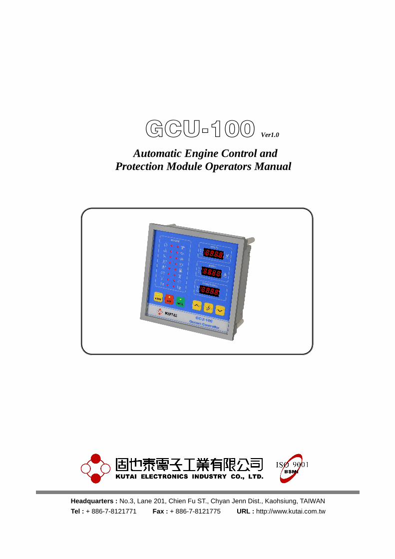
GCU-100 Ver1.0 Automatic Engine Control and
Protection Module Operators Manual
Headquarters : No.3, Lane 201, Chien Fu ST., Chyan Jenn Dist., Kaohsiung, TAIWAN
Tel : + 886-7-8121771 Fax : + 886-7-8121775 URL : http://www.kutai.com.tw

GCU-100 Automatic Engine Control and Protection Module
______________________________________________________________________________________
2
TABLE OF CONTENTS
Section Page
ATTENTION ............................................................................................................................................... 3
INTRODUCTION ........................................................................................................................................ 3
1. PANEL LAYOUT .................................................................................................................................... 4 1.1 Front Panel Layout............................................................................................................................ 4 1.2 Rear Panel Layout ............................................................................................................................ 5 1.3 Unit Dimensions (Measurement : mm) ............................................................................................. 6 1.4 Panel Cut-Out (Measurement : mm)................................................................................................. 6
2. OPERATION .......................................................................................................................................... 7 2.1 Summary........................................................................................................................................... 7 2.2 AUTO Mode ...................................................................................................................................... 7 2.3 MANU Mode...................................................................................................................................... 8 2.4 OFF Mode ......................................................................................................................................... 8
3. SYSTEM SETTING & OPERATION ...................................................................................................... 8 3.1 System Setting .................................................................................................................................. 8 3.2 Setting the Hour Meter ...................................................................................................................... 9 3.3 Setting the Magnetic Pick-up (MPU)................................................................................................. 9 3.4 Setting the AC Voltage and Current Display................................................................................... 10 3.5 Setting AC Voltage Protection ........................................................................................................ 10 3.6 Engine Over-load Protection Setting............................................................................................... 10 3.7 Panel Display Setting ...................................................................................................................... 10 3.8 Manual Start & Stop Operation ....................................................................................................... 11 3.9 Setting the Programmable Inputs Alarm1 and Alarm2 ................................................................... 11 3.10 Service and Maintenance Reminders ........................................................................................... 11 3.11 Engine Idle .................................................................................................................................... 11 3.12 Charge Alternator Excitation ......................................................................................................... 11 3.13 Setting Communication Modules GCU-100 to PC (KCU-XX)....................................................... 12 3.14 CANBus J1939 Transducer KCU-04 (Optional) ........................................................................... 12 3.15 Lamp Testing ................................................................................................................................ 12 3.16 System Setting Reference ............................................................................................................ 14
4. FAILURE WARNING DESCRIPTION .................................................................................................. 16 4.1 Failure Signal Reference................................................................................................................. 16 4.2 Warning Mode................................................................................................................................. 16 4.3 Shutdown Mode .............................................................................................................................. 16
5. SPECIFICATION .................................................................................................................................. 16
6. TERMINAL & WIRING DESCRIPTION ............................................................................................... 17 6.1 Connection Detail............................................................................................................................ 17 6.2 Three Phase System External Wiring Diagram .............................................................................. 18 6.3 Single Phase System External Wiring Diagram.............................................................................. 18
GCU-100 Automatic Engine Control and Protection Module
______________________________________________________________________________________
3
ATTENTION This manual contains information for operational maintenance and wiring connections, Read it carefully.
INTRODUCTION
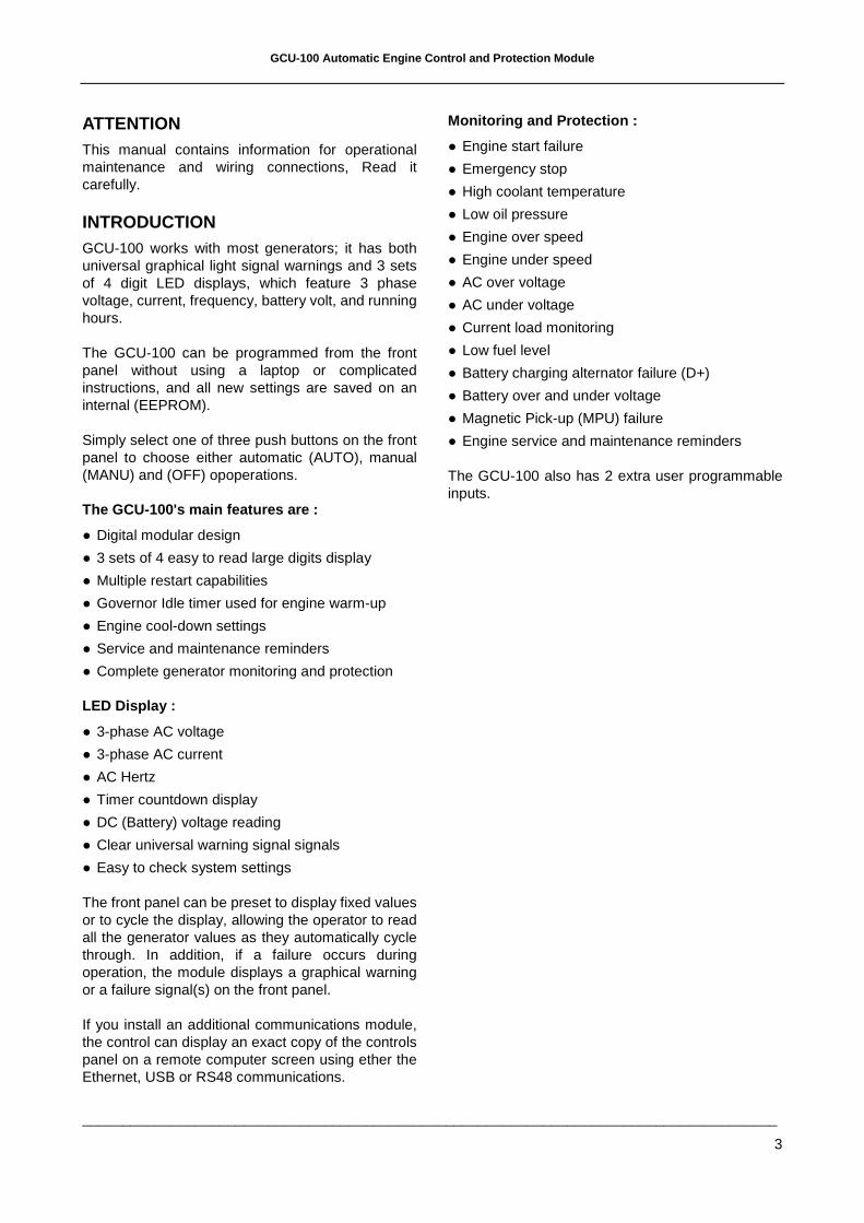
GCU-100 works with most generators; it has both universal graphical light signal warnings and 3 sets of 4 digit LED displays, which feature 3 phase voltage, current, frequency, battery volt, and running hours.
The GCU-100 can be programmed from the front panel without using a laptop or complicated instructions, and all new settings are saved on an internal (EEPROM).
Simply select one of three push buttons on the front panel to choose either automatic (AUTO), manual (MANU) and (OFF) opoperations.
The GCU-100's main features are :
● Digital modular design
● 3 sets of 4 easy to read large digits display
● Multiple restart capabilities
● Governor Idle timer used for engine warm-up
● Engine cool-down settings
● Service and maintenance reminders
● Complete generator monitoring and protection
LED Display :
● 3-phase AC voltage
● 3-phase AC current
● AC Hertz
● Timer countdown display
● DC (Battery) voltage reading
● Clear universal warning signal signals
● Easy to check system settings
The front panel can be preset to display fixed values or to cycle the display, allowing the operator to read all the generator values as they automatically cycle through. In addition, if a failure occurs during operation, the module displays a graphical warning or a failure signal(s) on the front panel.
If you install an additional communications module, the control can display an exact copy of the controls panel on a remote computer screen using ether the Ethernet, USB or RS48 communications.
Monitoring and Protection :
● Engine start failure
● Emergency stop
● High coolant temperature
● Low oil pressure
● Engine over speed
● Engine under speed
● AC over voltage
● AC under voltage
● Current load monitoring
● Low fuel level
● Battery charging alternator failure (D+)
● Battery over and under voltage
● Magnetic Pick-up (MPU) failure
● Engine service and maintenance reminders
The GCU-100 also has 2 extra user programmable inputs.
GCU-100 Automatic Engine Control and Protection Module
______________________________________________________________________________________
4
1. PANEL LAYOUT
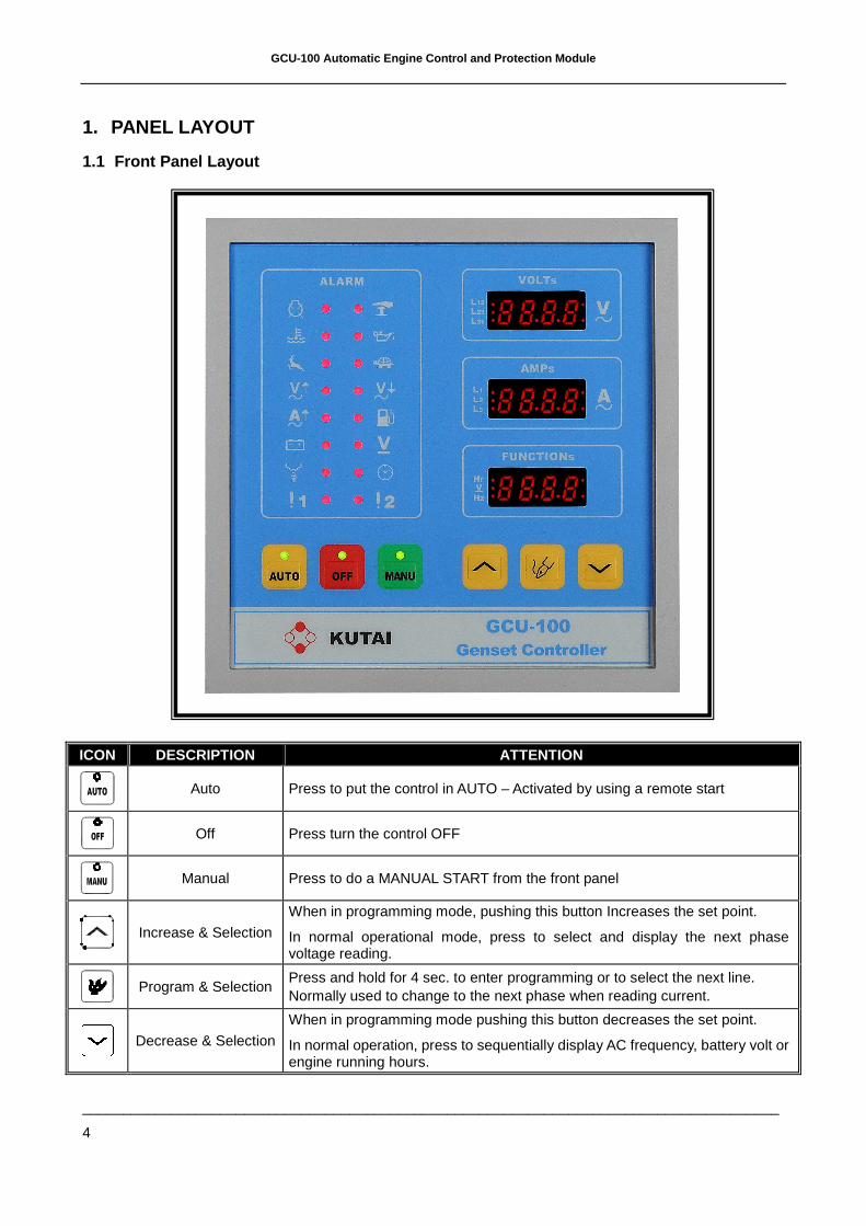
1.1 Front Panel Layout
ICON DESCRIPTION ATTENTION
Auto Press to put the control in AUTO – Activated by using a remote start
Off Press turn the control OFF
Manual Press to do a MANUAL START from the front panel
Increase & Selection
When in programming mode, pushing this button Increases the set point.
In normal operational mode, press to select and display the next phase voltage reading.
Program & Selection
Press and hold for 4 sec. to enter programming or to select the next line. Normally used to change to the next phase when reading current.
Decrease & Selection
When in programming mode pushing this button decreases the set point.
In normal operation, press to sequentially display AC frequency, battery volt or engine running hours.

GCU-100 Automatic Engine Control and Protection Module
______________________________________________________________________________________
5
1.2 Rear panel layout
GCU-100 Automatic Engine Control and Protection Module
______________________________________________________________________________________
6
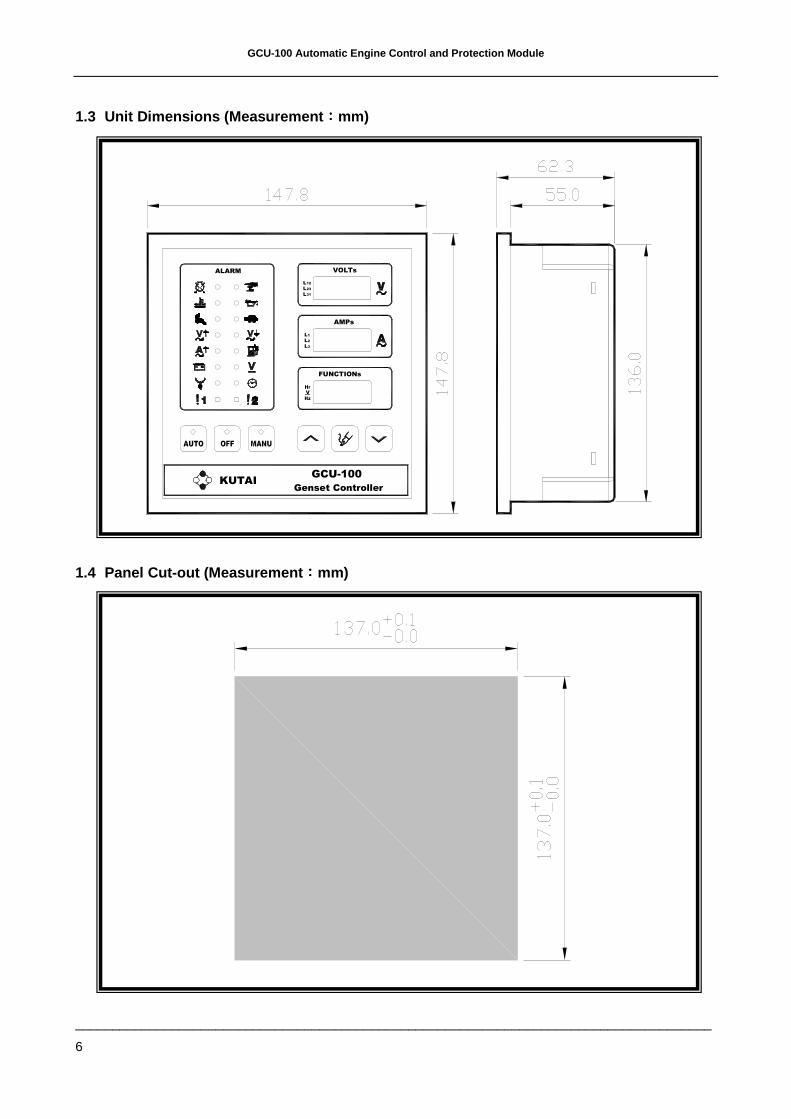
1.3 Unit Dimensions (Measurement ::::mm)
1.4 Panel Cut-out (Measurement ::::mm)
ALARM
GCU-100
Genset ControllerKUTAI
FUNCTIONs
AMPs
31L
12L 23L
3
2
L
1L L
V
VOLTs
GCU-100 Automatic Engine Control and Protection Module
______________________________________________________________________________________
7
2. OPERATION
2.1 Summary
GCU-100 Operation :
1. AUTO : In AUTO Start Mode (Remote Start)
2. MANU : Manual Start Mode
3. OFF : Engine Stop / Reset
Select only one button at a time. The buttons have double functions, depending if you are programming the control or in normal operation.
2.2 AUTO Mode
In AUTO, the module governs the start and stop of the gen-set . The flashing LED on the AUTO button indicates the control is in AUTO and waiting for a start signal, the moment this signal is received by grounding terminals J1-17, the LED stops flashing, and the generator initiates its auto start sequence.
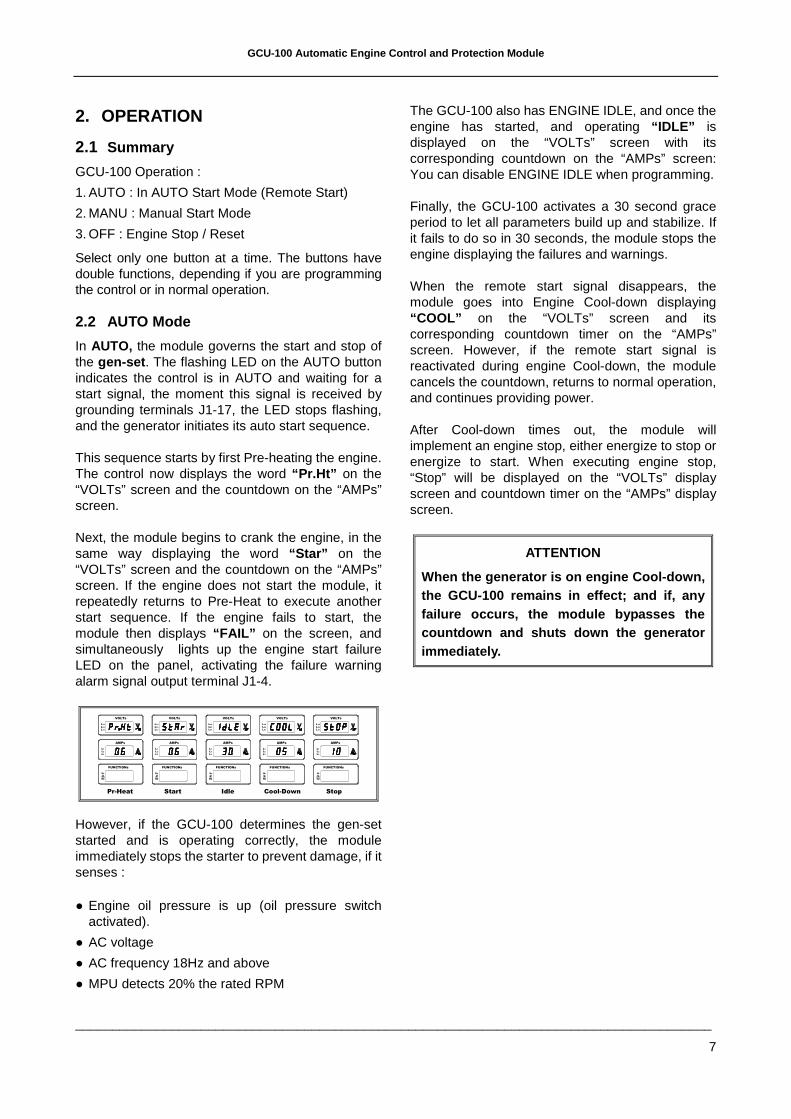
This sequence starts by first Pre-heating the engine. The control now displays the word “Pr.Ht” on the “VOLTs” screen and the countdown on the “AMPs” screen.
Next, the module begins to crank the engine, in the same way displaying the word “Star” on the “VOLTs” screen and the countdown on the “AMPs” screen. If the engine does not start the module, it repeatedly returns to Pre-Heat to execute another start sequence. If the engine fails to start, the module then displays “FAIL” on the screen, and simultaneously lights up the engine start failure LED on the panel, activating the failure warning alarm signal output terminal J1-4.
FUNCTIONs
AMPs
31L
12L 23L
3
2
L
1L L
V
VOLTs
FUNCTIONs
AMPs
31L
12L 23L
3
2
L
1L L
V
VOLTs
FUNCTIONs
AMPs
31L
12L 23L
3
2
L
1L L
V
VOLTs
FUNCTIONs
AMPs
31L
12L 23L
3
2
L
1L L
V
VOLTs
FUNCTIONs
AMPs
31L
12L 23L
3
2
L
1L L
V
VOLTs
Pr-Heat Start Idle Cool-Down Stop
However, if the GCU-100 determines the gen-set started and is operating correctly, the module immediately stops the starter to prevent damage, if it senses :
● Engine oil pressure is up (oil pressure switch activated).
● AC voltage
● AC frequency 18Hz and above
● MPU detects 20% the rated RPM
The GCU-100 also has ENGINE IDLE, and once the engine has started, and operating “IDLE” is displayed on the “VOLTs” screen with its corresponding countdown on the “AMPs” screen: You can disable ENGINE IDLE when programming.
Finally, the GCU-100 activates a 30 second grace period to let all parameters build up and stabilize. If it fails to do so in 30 seconds, the module stops the engine displaying the failures and warnings.
When the remote start signal disappears, the module goes into Engine Cool-down displaying “COOL” on the “VOLTs” screen and its corresponding countdown timer on the “AMPs” screen. However, if the remote start signal is reactivated during engine Cool-down, the module cancels the countdown, returns to normal operation, and continues providing power.
After Cool-down times out, the module will implement an engine stop, either energize to stop or energize to start. When executing engine stop, “Stop” will be displayed on the “VOLTs” display screen and countdown timer on the “AMPs” display screen.
ATTENTION
When the generator is on engine Cool-down, the GCU-100 remains in effect; and if, any failure occurs, the module bypasses the countdown and shuts down the generator immediately.
GCU-100 Automatic Engine Control and Protection Module
______________________________________________________________________________________
8
2.3 MANU Mode
In MANUAL , you can start and stop the gen-set manually. If you press the OFF button, the gen-set will make the normal programmed shutdown.
In AUTO and MANUAL the engine start and stop program are almost identical but in MANUAL , engine Cool-down is not used. Reference chapter 2.2.
2.4 OFF Mode
Press the OFF button to shut down the gen-set or also for fault failure RESET. If the OFF button is pushed during normal operation, the program omits engine Cool-down execute engine shut down immediately.
If a major malfunction is detected during operation, the module immediately shuts down the gen-set to prevent further damage to the equipment or operating personnel. The display shows all failures at the same time on the front panel so maintenance service can carry out necessary repairs. To reset the warning(s) and failures, press the “OFF” button.
3. SYSTEM SETTING & OPERATION
ATTENTION
Before proceeding to system setting, make sure all wiring and batteries are connected.
3.1 System Setting
There are total of 53 programmable setting in the GCU-100, you can program the module according to different gen-set operation controls and protection preferences by pressing the setting key / buttons on the front panel. To start, press OFF and then press and hold the program (pen) button for 4 seconds.
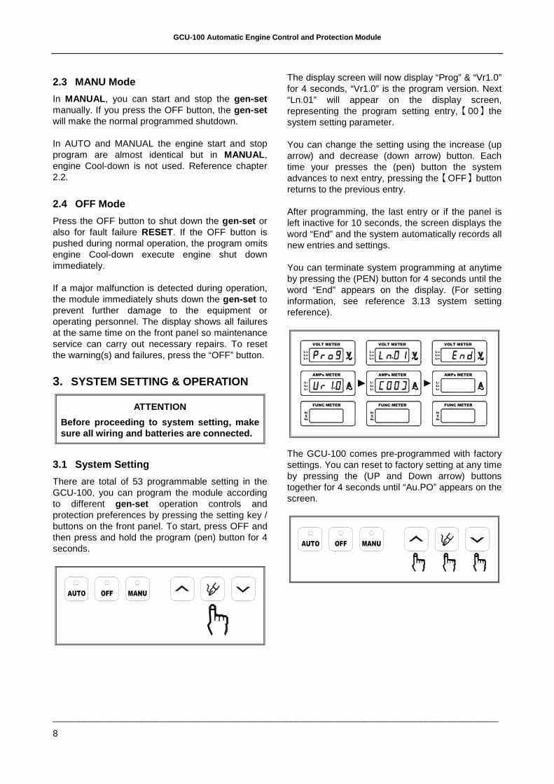
The display screen will now display “Prog” & “Vr1.0” for 4 seconds, “Vr1.0” is the program version. Next “Ln.01” will appear on the display screen, representing the program setting entry,【00】the system setting parameter.
You can change the setting using the increase (up arrow) and decrease (down arrow) button. Each time your presses the (pen) button the system advances to next entry, pressing the【OFF】button returns to the previous entry.
After programming, the last entry or if the panel is left inactive for 10 seconds, the screen displays the word “End” and the system automatically records all new entries and settings.
You can terminate system programming at anytime by pressing the (PEN) button for 4 seconds until the word “End” appears on the display. (For setting information, see reference 3.13 system setting reference).
FUNC METER
AMPs METER
31L
12L 23L
3
2
L
1L L
V
VOLT METER
FUNC METER
AMPs METER
31L
12L 23L
3
2
L
1L L
V
VOLT METER
FUNC METER
AMPs METER
31L
12L 23L
3
2
L
1L L
V
VOLT METER
The GCU-100 comes pre-programmed with factory settings. You can reset to factory setting at any time by pressing the (UP and Down arrow) buttons together for 4 seconds until “Au.PO” appears on the screen.
GCU-100 Automatic Engine Control and Protection Module
______________________________________________________________________________________
9
FUNCTIONs
AMPs
31L
12L 23L
3
2
L
1L L
V
VOLTs
FUNCTIONs
AMPs
31L
12L 23L
3
2
L
1L L
V
VOLTs
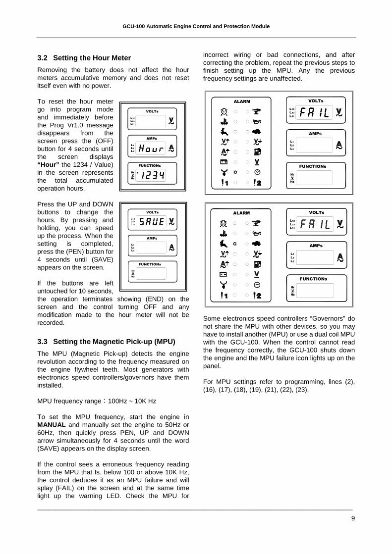
3.2 Setting the Hour Meter
Removing the battery does not affect the hour meters accumulative memory and does not reset itself even with no power.
To reset the hour meter go into program mode and immediately before the Prog Vr1.0 message disappears from the screen press the (OFF) button for 4 seconds until the screen displays “Hour” the 1234 / Value) in the screen represents the total accumulated operation hours.
Press the UP and DOWN buttons to change the hours. By pressing and holding, you can speed up the process. When the setting is completed, press the (PEN) button for 4 seconds until (SAVE) appears on the screen.
If the buttons are left untouched for 10 seconds, the operation terminates showing (END) on the screen and the control turning OFF and any modification made to the hour meter will not be recorded.
3.3 Setting the Magnetic Pick-up (MPU)
The MPU (Magnetic Pick-up) detects the engine revolution according to the frequency measured on the engine flywheel teeth. Most generators with electronics speed controllers/governors have them installed.
MPU frequency range:100Hz ~ 10K Hz
To set the MPU frequency, start the engine in MANUAL and manually set the engine to 50Hz or 60Hz, then quickly press PEN, UP and DOWN arrow simultaneously for 4 seconds until the word (SAVE) appears on the display screen.
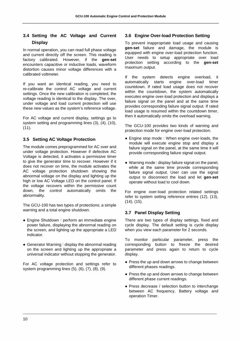
If the control sees a erroneous frequency reading from the MPU that Is. below 100 or above 10K Hz, the control deduces it as an MPU failure and will splay (FAIL) on the screen and at the same time light up the warning LED. Check the MPU for
incorrect wiring or bad connections, and after correcting the problem, repeat the previous steps to finish setting up the MPU. Any the previous frequency settings are unaffected.
FUNCTIONs
AMPs
31L
12L 23L
3
2
L
1L L
V
VOLTsALARM
FUNCTIONs
AMPs
31L
12L 23L
3
2
L
1L L
V
VOLTsALARM
Some electronics speed controllers “Governors” do not share the MPU with other devices, so you may have to install another (MPU) or use a dual coil MPU with the GCU-100. When the control cannot read the frequency correctly, the GCU-100 shuts down the engine and the MPU failure icon lights up on the panel.
For MPU settings refer to programming, lines (2), (16), (17), (18), (19), (21), (22), (23).
GCU-100 Automatic Engine Control and Protection Module
______________________________________________________________________________________
10
3.4 Setting the AC Voltage and Current
Display
In normal operation, you can read full phase voltage and current directly off the screen. This reading is factory calibrated. However, if the gen-set encounters capacitive or inductive loads, waveform distortion causes minor voltage differences with a calibrated voltmeter.
If you want an identical reading, you need to re-calibrate the control AC voltage and current settings. Once the new calibration is completed, the voltage reading is identical to the display. The over, under voltage and load current protection will use these new values as the system’s reference voltage.
For AC voltage and current display, settings go to system setting and programming lines (3), (4), (10), (11).
3.5 Setting AC Voltage Protection
The module comes preprogrammed for AC over and under voltage protection. However if defective AC Voltage is detected, it activates a permissive timer to give the generator time to recover. However if it does not recover on time, the module activates the AC voltage protection shutdown showing the abnormal voltage on the display and lighting up the high or low AC Voltage LED on the control panel. If the voltage recovers within the permissive count down, the control automatically omits the abnormality.
The GCU-100 has two types of protections; a simple warning and a total engine shutdown.
● Engine Shutdown:perform an immediate engine power failure, displaying the abnormal reading on the screen, and lighting up the appropriate a LED indicator.
● Generator Warning:display the abnormal reading on the screen and lighting up the appropriate a universal indicator without stopping the generator.
For AC voltage protection and settings refer to system programming lines (5), (6), (7), (8), (9).
3.6 Engine Over-load Protection Setting
To prevent inappropriate load usage and causing gen-set failure and damage, the module is equipped with engine over-load protection function. User needs to setup appropriate over load protection setting according to the gen-set maximum output.
If the system detects engine overload, it automatically starts engine over-load timer countdown. If rated load usage does not recover within the countdown, the system automatically executes engine over-load protection and displays a failure signal on the panel and at the same time provides corresponding failure signal output. If rated load usage is resumed within the countdown timer, then it automatically omits the overload warning.
The GCU-100 provides two kinds of warning and protection mode for engine over-load protection.
● Engine stop mode:When engine over-loads, the module will execute engine stop and display a failure signal on the panel, at the same time it will provide corresponding failure signal output.
● Warning mode:display failure signal on the panel, while at the same time provide corresponding failure signal output. User can use the signal output to disconnect the load and let gen-set operate without load to cool down.
For engine over-load protection related settings refer to system setting reference entries (12), (13), (14), (15).
3.7 Panel Display Setting
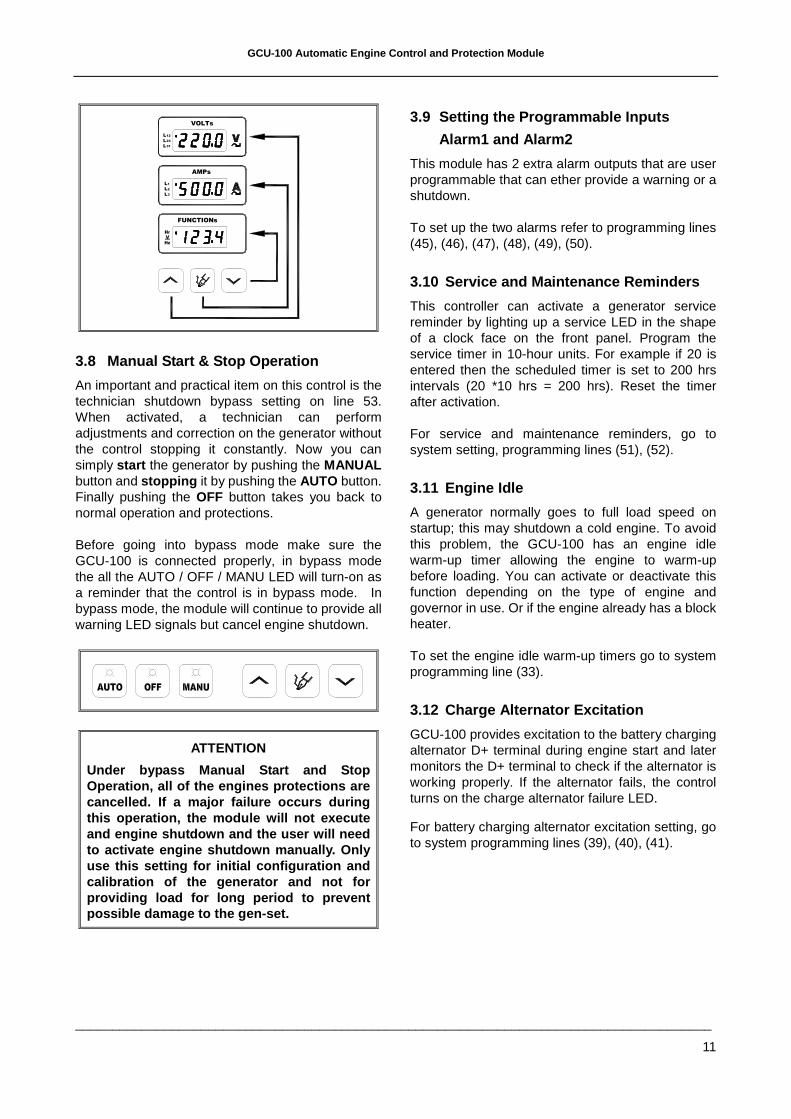
There are two types of display settings, fixed and cycle display. The default setting is cycle display when you view each parameter for 2 seconds.
To monitor particular parameter, press the corresponding button to freeze the desired parameter and press again to return to cycle display.
● Press the up and down arrows to change between different phases readings.
● Press the up and down arrows to change between different phase current readings.
● Press decrease / selection button to interchange between AC frequency, Battery voltage and operation Timer.
GCU-100 Automatic Engine Control and Protection Module
______________________________________________________________________________________
11
FUNCTIONs
AMPs
31L
12L 23L
3
2
L
1L L
V
VOLTs
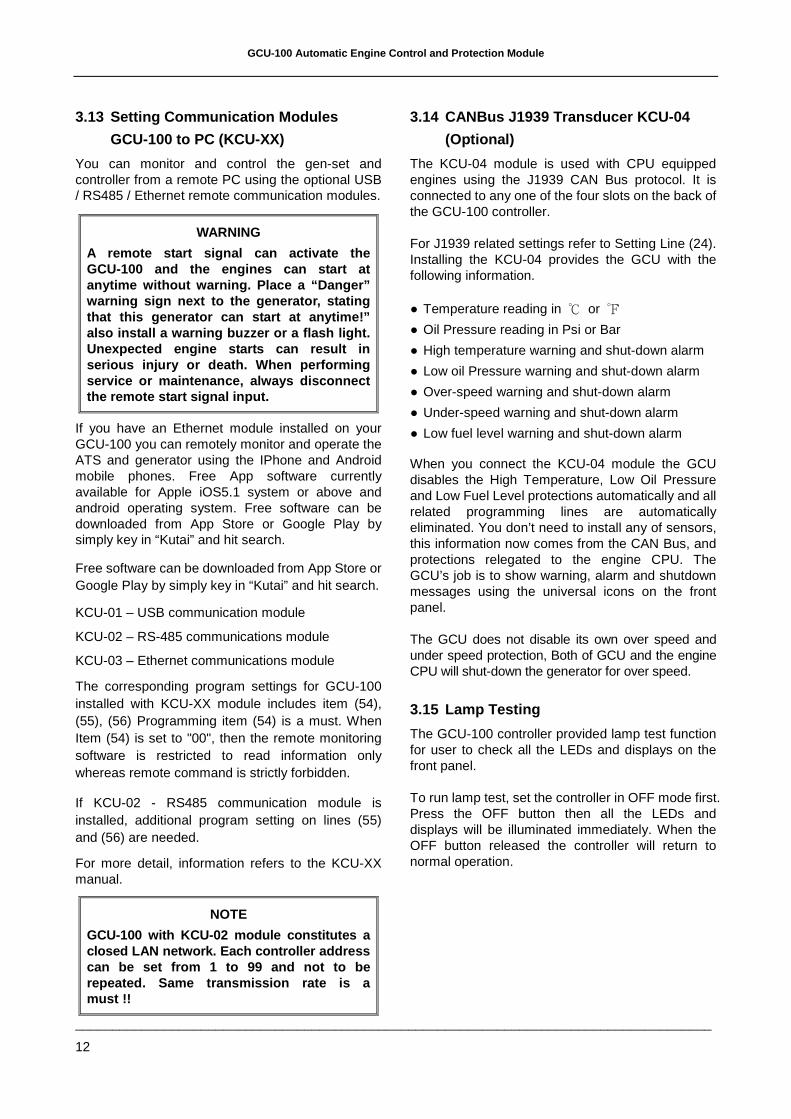
3.8 Manual Start & Stop Operation
An important and practical item on this control is the technician shutdown bypass setting on line 53. When activated, a technician can perform adjustments and correction on the generator without the control stopping it constantly. Now you can simply start the generator by pushing the MANUAL button and stopping it by pushing the AUTO button. Finally pushing the OFF button takes you back to normal operation and protections.
Before going into bypass mode make sure the GCU-100 is connected properly, in bypass mode the all the AUTO / OFF / MANU LED will turn-on as a reminder that the control is in bypass mode. In bypass mode, the module will continue to provide all warning LED signals but cancel engine shutdown.
ATTENTION
Under bypass Manual Start and Stop Operation, all of the engines protections are cancelled. If a major failure occurs during this operation, the module will not execute and engine shutdown and the user will need to activate engine shutdown manually. Only use this setting for initial configuration and calibration of the generator and not for providing load for long period to prevent possible damage to the gen-set.
3.9 Setting the Programmable Inputs
Alarm1 and Alarm2
This module has 2 extra alarm outputs that are user programmable that can ether provide a warning or a shutdown.
To set up the two alarms refer to programming lines (45), (46), (47), (48), (49), (50).
3.10 Service and Maintenance Reminders
This controller can activate a generator service reminder by lighting up a service LED in the shape of a clock face on the front panel. Program the service timer in 10-hour units. For example if 20 is entered then the scheduled timer is set to 200 hrs intervals (20 *10 hrs = 200 hrs). Reset the timer after activation.
For service and maintenance reminders, go to system setting, programming lines (51), (52).
3.11 Engine Idle
A generator normally goes to full load speed on startup; this may shutdown a cold engine. To avoid this problem, the GCU-100 has an engine idle warm-up timer allowing the engine to warm-up before loading. You can activate or deactivate this function depending on the type of engine and governor in use. Or if the engine already has a block heater.
To set the engine idle warm-up timers go to system programming line (33).
3.12 Charge Alternator Excitation
GCU-100 provides excitation to the battery charging alternator D+ terminal during engine start and later monitors the D+ terminal to check if the alternator is working properly. If the alternator fails, the control turns on the charge alternator failure LED.
For battery charging alternator excitation setting, go to system programming lines (39), (40), (41).
GCU-100 Automatic Engine Control and Protection Module
______________________________________________________________________________________
12
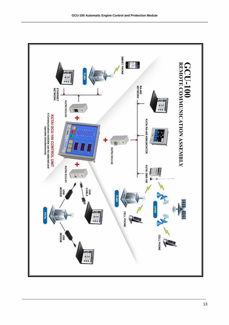
3.13 Setting Communication Modules
GCU-100 to PC (KCU-XX)
You can monitor and control the gen-set and controller from a remote PC using the optional USB / RS485 / Ethernet remote communication modules.
WARNING
A remote start signal can activate the GCU-100 and the engines can start at anytime without warning. Place a “Danger” warning sign next to the generator, stating that this generator can start at anytime!” also install a warning buzzer or a flash light. Unexpected engine starts can result in serious injury or death. When performing service or maintenance, always disconnect the remote start signal input.
If you have an Ethernet module installed on your GCU-100 you can remotely monitor and operate the ATS and generator using the IPhone and Android mobile phones. Free App software currently available for Apple iOS5.1 system or above and android operating system. Free software can be downloaded from App Store or Google Play by simply key in “Kutai” and hit search.
Free software can be downloaded from App Store or Google Play by simply key in “Kutai” and hit search.
KCU-01 – USB communication module
KCU-02 – RS-485 communications module
KCU-03 – Ethernet communications module
The corresponding program settings for GCU-100 installed with KCU-XX module includes item (54), (55), (56) Programming item (54) is a must. When Item (54) is set to "00", then the remote monitoring software is restricted to read information only whereas remote command is strictly forbidden.
If KCU-02 - RS485 communication module is installed, additional program setting on lines (55) and (56) are needed.
For more detail, information refers to the KCU-XX manual.
NOTE
GCU-100 with KCU-02 module constitutes a closed LAN network. Each controller address can be set from 1 to 99 and not to be repeated. Same transmission rate is a must !!
3.14 CANBus J1939 Transducer KCU-04
(Optional)
The KCU-04 module is used with CPU equipped engines using the J1939 CAN Bus protocol. It is connected to any one of the four slots on the back of the GCU-100 controller.
For J1939 related settings refer to Setting Line (24). Installing the KCU-04 provides the GCU with the following information.
● Temperature reading in ℃ or ℉
● Oil Pressure reading in Psi or Bar
● High temperature warning and shut-down alarm
● Low oil Pressure warning and shut-down alarm
● Over-speed warning and shut-down alarm
● Under-speed warning and shut-down alarm
● Low fuel level warning and shut-down alarm
When you connect the KCU-04 module the GCU disables the High Temperature, Low Oil Pressure and Low Fuel Level protections automatically and all related programming lines are automatically eliminated. You don’t need to install any of sensors, this information now comes from the CAN Bus, and protections relegated to the engine CPU. The GCU’s job is to show warning, alarm and shutdown messages using the universal icons on the front panel.
The GCU does not disable its own over speed and under speed protection, Both of GCU and the engine CPU will shut-down the generator for over speed.
3.15 Lamp Testing
The GCU-100 controller provided lamp test function for user to check all the LEDs and displays on the front panel.
To run lamp test, set the controller in OFF mode first. Press the OFF button then all the LEDs and displays will be illuminated immediately. When the OFF button released the controller will return to normal operation.
GCU-100 Automatic Engine Control and Protection Module
______________________________________________________________________________________
13
GCU-100 Automatic Engine Control and Protection Module
______________________________________________________________________________________
14
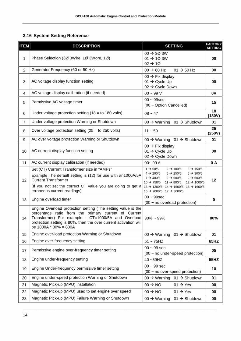
3.16 System Setting Reference
ITEM DESCRIPTION SETTING FACTORY SETTING
1 Phase Selection (3Ø 3Wire, 1Ø 3Wore, 1Ø) 00 � 3Ø 3W 01 � 1Ø 3W 02 � 1Ø
00
2 Generator Frequency (60 or 50 Hz) 00 � 60 Hz 01 � 50 Hz 00
3 AC voltage display function setting 00 � Fix display 01 � Cycle Up 02 � Cycle Down
00
4 AC voltage display calibration (if needed) 00 ~ 99 V 0V
5 Permissive AC voltage timer 00 ~ 99sec (00 − Option Cancelled)
15
6 Under voltage protection setting (18 = to 180 volts) 08 ~ 47 18
(180V)
7 Under voltage protection Warning or Shutdown 00 � Warning 01 � Shutdown 01
8 Over voltage protection setting (25 = to 250 volts) 11 ~ 50 25
(250V)
9 AC over voltage protection Warning or Shutdown 00 � Warning 01 � Shutdown 01
10 AC current display function setting 00 � Fix display 01 � Cycle Up 02 � Cycle Down
00
11 AC current display calibration (if needed) 00~ 99 A 0 A
12
Set (CT) Current Transformer size in “AMPs”
Example The default setting is (12) for use with an1000A/5A Current Transformer
(If you not set the correct CT value you are going to get a erroneous current readings)
1 � 50/5 2 � 100/5 3 � 150/5 4 � 200/5 5 � 250/5 6 � 300/5 7 � 400/5 8 � 500/5 9 � 600/5 10 � 750/5 11 � 800/5 12 � 1000/5 13 � 1200/5 14 � 1500/5 15 � 1600/5 16 � 2000/5 17 � 3000/5
12
13 Engine overload timer 00 ~ 99sec (00 − no overload protection)
0
14
Engine Overload protection setting (The setting value is the percentage ratio from the primary current of Current Transformer) For example : CT=1000/5A and Overload protection setting is 80%, then the over current activation will be 1000A * 80% = 800A
30% ~ 99% 80%
15 Engine over-load protection Warning or Shutdown 00 � Warning 01 � Shutdown 01
16 Engine over-frequency setting 51 ~ 75HZ 65HZ
17 Permissive engine over-frequency timer setting 00 ~ 99 sec (00 − no under-speed protection)
05
18 Engine under-frequency setting 40 ~59HZ 55HZ
19 Engine Under-frequency permissive timer setting 00 ~ 99 sec (00 − no over-speed protection)
10
20 Engine under-speed protection Warning or Shutdown 00 � Warning 01 � Shutdown 01
21 Magnetic Pick-up (MPU) installation 00 � NO 01 � Yes 00
22 Magnetic Pick-up (MPU) used to set engine over speed 00 � NO 01 � Yes 00
23 Magnetic Pick-up (MPU) Failure Warning or Shutdown 00 � Warning 01 � Shutdown 00
GCU-100 Automatic Engine Control and Protection Module
______________________________________________________________________________________
15
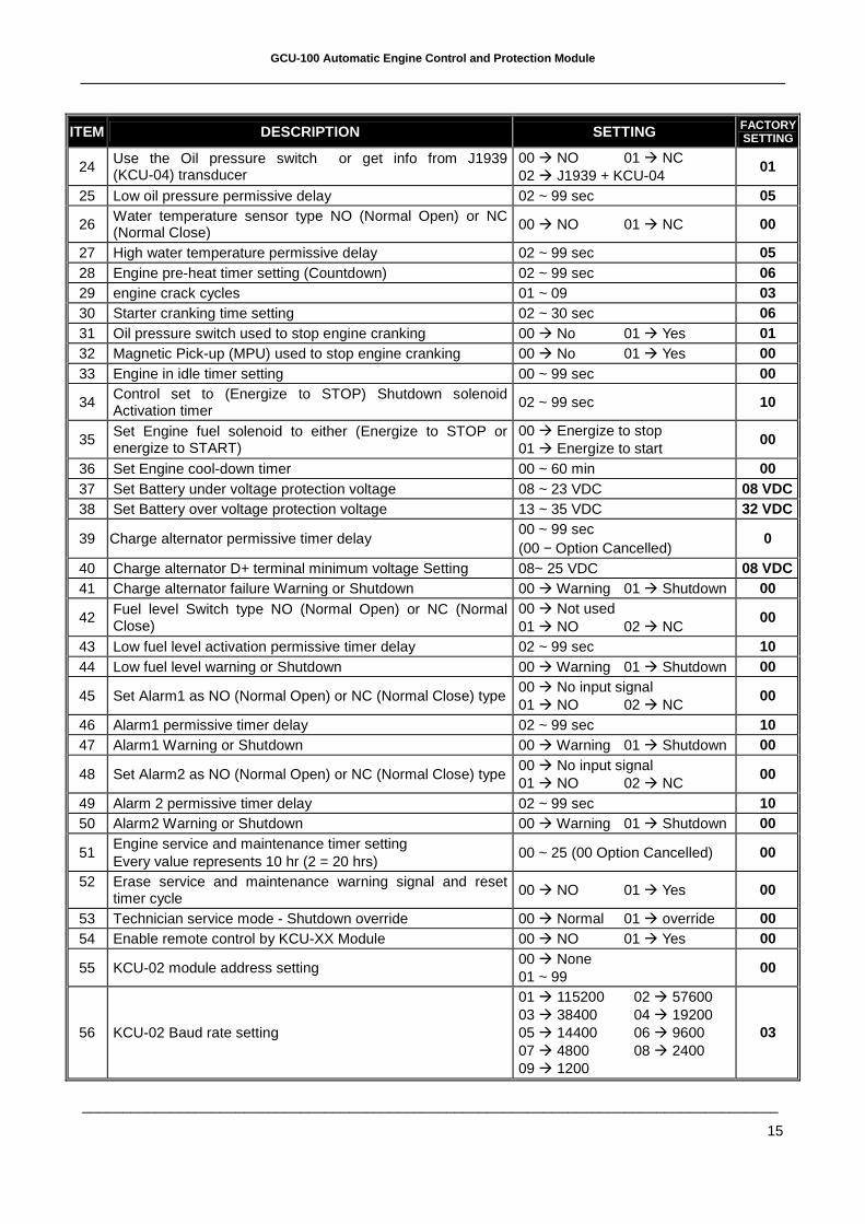
ITEM DESCRIPTION SETTING FACTORY SETTING
24 Use the Oil pressure switch or get info from J1939 (KCU-04) transducer
00 � NO 01 � NC 02 � J1939 + KCU-04
01
25 Low oil pressure permissive delay 02 ~ 99 sec 05
26 Water temperature sensor type NO (Normal Open) or NC (Normal Close) 00 � NO 01 � NC 00
27 High water temperature permissive delay 02 ~ 99 sec 05 28 Engine pre-heat timer setting (Countdown) 02 ~ 99 sec 06 29 engine crack cycles 01 ~ 09 03 30 Starter cranking time setting 02 ~ 30 sec 06 31 Oil pressure switch used to stop engine cranking 00 � No 01 � Yes 01 32 Magnetic Pick-up (MPU) used to stop engine cranking 00 � No 01 � Yes 00 33 Engine in idle timer setting 00 ~ 99 sec 00
34 Control set to (Energize to STOP) Shutdown solenoid Activation timer
02 ~ 99 sec 10
35 Set Engine fuel solenoid to either (Energize to STOP or energize to START)
00 � Energize to stop 01 � Energize to start
00
36 Set Engine cool-down timer 00 ~ 60 min 00 37 Set Battery under voltage protection voltage 08 ~ 23 VDC 08 VDC 38 Set Battery over voltage protection voltage 13 ~ 35 VDC 32 VDC
39 Charge alternator permissive timer delay 00 ~ 99 sec (00 − Option Cancelled)
0
40 Charge alternator D+ terminal minimum voltage Setting 08~ 25 VDC 08 VDC 41 Charge alternator failure Warning or Shutdown 00 � Warning 01 � Shutdown 00
42 Fuel level Switch type NO (Normal Open) or NC (Normal Close)
00 � Not used 01 � NO 02 � NC
00
43 Low fuel level activation permissive timer delay 02 ~ 99 sec 10 44 Low fuel level warning or Shutdown 00 � Warning 01 � Shutdown 00
45 Set Alarm1 as NO (Normal Open) or NC (Normal Close) type 00 � No input signal 01 � NO 02 � NC
00
46 Alarm1 permissive timer delay 02 ~ 99 sec 10 47 Alarm1 Warning or Shutdown 00 � Warning 01 � Shutdown 00
48 Set Alarm2 as NO (Normal Open) or NC (Normal Close) type 00 � No input signal 01 � NO 02 � NC
00
49 Alarm 2 permissive timer delay 02 ~ 99 sec 10 50 Alarm2 Warning or Shutdown 00 � Warning 01 � Shutdown 00
51 Engine service and maintenance timer setting Every value represents 10 hr (2 = 20 hrs)
00 ~ 25 (00 Option Cancelled) 00
52 Erase service and maintenance warning signal and reset timer cycle
00 � NO 01 � Yes 00
53 Technician service mode - Shutdown override 00 � Normal 01 � override 00 54 Enable remote control by KCU-XX Module 00 � NO 01 � Yes 00
55 KCU-02 module address setting 00 � None 01 ~ 99
00
56 KCU-02 Baud rate setting
01 � 115200 02 � 57600 03 � 38400 04 � 19200 05 � 14400 06 � 9600 07 � 4800 08 � 2400 09 � 1200
03
GCU-100 Automatic Engine Control and Protection Module
______________________________________________________________________________________
16
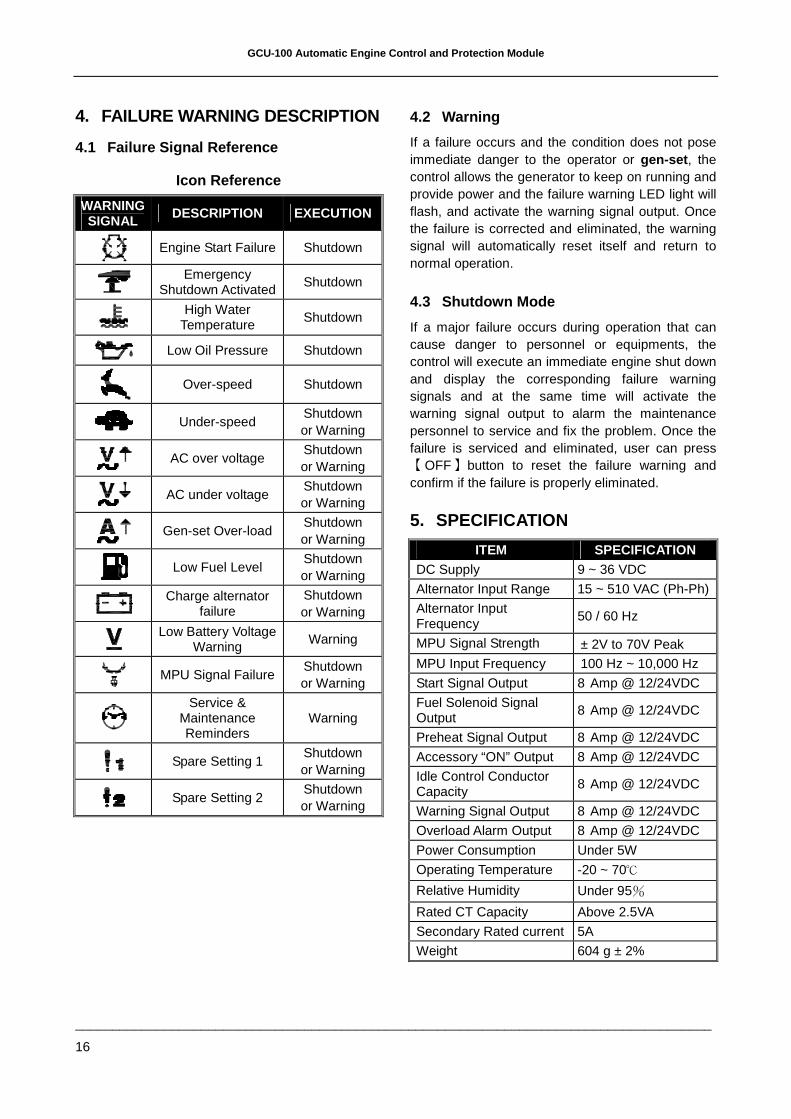
4. FAILURE WARNING DESCRIPTION
4.1 Failure Signal Reference
Icon Reference
WARNING SIGNAL DESCRIPTION EXECUTION
Engine Start Failure Shutdown
Emergency
Shutdown Activated Shutdown
High Water
Temperature Shutdown
Low Oil Pressure Shutdown
Over-speed Shutdown
Under-speed Shutdown or Warning
AC over voltage
Shutdown or Warning
AC under voltage
Shutdown or Warning
Gen-set Over-load
Shutdown or Warning
Low Fuel Level
Shutdown or Warning
Charge alternator
failure Shutdown or Warning
Low Battery Voltage
Warning Warning
MPU Signal Failure
Shutdown or Warning
Service & Maintenance Reminders
Warning
Spare Setting 1 Shutdown or Warning
Spare Setting 2 Shutdown or Warning
4.2 Warning
If a failure occurs and the condition does not pose immediate danger to the operator or gen-set , the control allows the generator to keep on running and provide power and the failure warning LED light will flash, and activate the warning signal output. Once the failure is corrected and eliminated, the warning signal will automatically reset itself and return to normal operation.
4.3 Shutdown Mode
If a major failure occurs during operation that can cause danger to personnel or equipments, the control will execute an immediate engine shut down and display the corresponding failure warning signals and at the same time will activate the warning signal output to alarm the maintenance personnel to service and fix the problem. Once the failure is serviced and eliminated, user can press 【OFF】button to reset the failure warning and confirm if the failure is properly eliminated.
5. SPECIFICATION
ITEM SPECIFICATION DC Supply 9 ~ 36 VDC
Alternator Input Range 15 ~ 510 VAC (Ph-Ph)
Alternator Input Frequency
50 / 60 Hz
MPU Signal Strength ± 2V to 70V Peak
MPU Input Frequency 100 Hz ~ 10,000 Hz
Start Signal Output 8 Amp @ 12/24VDC
Fuel Solenoid Signal Output
8 Amp @ 12/24VDC
Preheat Signal Output 8 Amp @ 12/24VDC
Accessory “ON” Output 8 Amp @ 12/24VDC
Idle Control Conductor Capacity
8 Amp @ 12/24VDC
Warning Signal Output 8 Amp @ 12/24VDC
Overload Alarm Output 8 Amp @ 12/24VDC
Power Consumption Under 5W
Operating Temperature -20 ~ 70℃
Relative Humidity Under 95%
Rated CT Capacity Above 2.5VA
Secondary Rated current 5A
Weight 604 g ± 2%

GCU-100 Automatic Engine Control and Protection Module
______________________________________________________________________________________
17
6. TERMINAL & WIRING DESCRIPTION
6.1 Connection Detail
PIN No. DESCRIPTION ATTENTION
J1-1 Charge alternator D+ terminal input
Connect to charge alternator D+ terminals
J1-2 Battery negative ( −V ) Connect to battery negative
J1-3 Battery positive ( +V ) Connect to battery positive (12 / 24V)
J1-4 Failure signal output Used to control external alarm buzzer Supply (+V) (Max. rated output 8Amp)
J1-5 Idle speed control signal output Connect to electronic governor for idle speed control Supply (+V) (Max. rated output 8Amp)
J1-6 Starter motor signal output Connect to starter motor Supply (+V) (Max. rated output 8Amp)
J1-7 Fuel solenoid signal output Connect to fuel solenoid or fuel valve control Supply (+V) (Max. rated output 8Amp)
J1-8 Accessory on output Connect to the panel lamp (Max. rated output 8Amp)
J1-9 Overload alarm signal output Used to trip the AC output breaker Supply (+V) (Max. rated output 8Amp)
J1-10 Preheat signal output Used to control the internal heater Supply (+V) (Max. rated output 8Amp)
J1-11 Emergency stop signal output Connect to panel emergency stop push button
J1-12 High water temperature signal input Connect to water temperature switch
J1-13 Low oil pressure signal input to oil pressure switch or J1939 reader dry contact
J1-14 Low fuel signal input connect to fuel level switch
J1-15 User defined signal input 2 Negative input when action
J1-16 User defined signal input 1 Negative input when action
J1-17 Remote start signal input Connect to A.T.S or remote start terminal
J1-18 Spare terminal
J2-1 Spare terminal
J2-2 Spare terminal
J2-3 Spare terminal
J3-1 Magnetic Pick-up input Connect to magnetic Pick-up to monitor engine speed
J3-2 Magnetic Pick-up input Connect to magnetic Pick-up to monitor engine speed
J3-3 Spare terminal
J3-4 Spare terminal
J3-5 Spare terminal
J3-6 Spare terminal
J3-7 CT (COMM) terminal input Connect to external CTs common position
J3-8 CT Secondary for (L1) Connect to secondary phase R (L1) monitoring CT
J3-9 CT Secondary for (L2) Connect to secondary phase S (L2) monitoring CT
J3-10 CT Secondary for (L3) Connect to secondary phase T (L3) monitoring CT
J4-1 AC Input (L1) Connect to AC input phase R
J4-2 AC Input (L2) Connect to AC input phase S
J4-3 AC Input (L3) Connect to AC input phase T
GCU-100 Automatic Engine Control and Protection Module
______________________________________________________________________________________
18
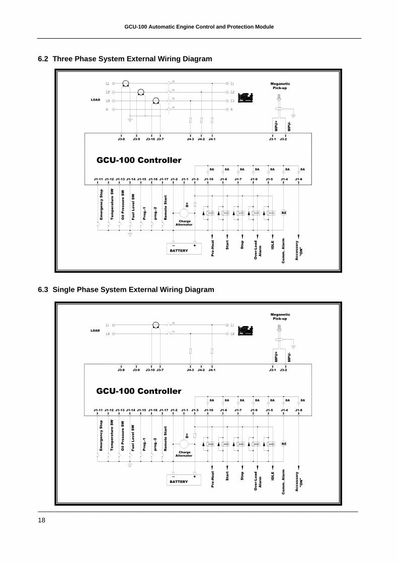
6.2 Three Phase System External Wiring Diagram
6.3 Single Phase System External Wiring Diagram
J1-3J1-2J1-12 J1-13 J1-14 J1-17J1-15J1-11 J1-16
J3-1 J3-2
LOAD
J1-5 J1-4J1-6 J1-8J1-7 J1-9J1-10
J3-9 J4-2J4-3 J4-1J3-7J3-8 J3-10
BATTERY
Em
erg
enc
y S
top
Oil P
ressure
SW
Tem
pera
ture
SW
pro
g.-
2
Pro
g.-1
Fue
l L
eve
l S
W
Rem
ote
Sta
rt
Acc
esso
ry
Pre
-Heat
+S
top
Sta
rt
IDL
E
Ove
r-Lo
ad
Ala
rm
Co
mm
. A
larm
BZ
"O
N"
GCU-100 Controller8A 8A 8A 8A 8A 8A 8A
Pick-up
Meganetic
MP
U-
MP
U+
D+
ChargeAlternator
J1-1
J1-1
AlternatorCharge
D+
MP
U+
MP
U-
Meganetic
Pick-up
8A8A8A8A8A8A8A
GCU-100 Controller
"O
N"
BZ
Co
mm
. A
larm
Ala
rm
Ove
r-L
oad
IDL
E
Sta
rt
Sto
p
+
Pre
-Hea
t
Acc
essory
Rem
ote
Sta
rt
Fue
l L
eve
l S
W
Pro
g.-1
pro
g.-
2
Te
mp
era
ture
SW
Oil P
ressure
SW
Em
erg
en
cy S
top
BATTERY
J1-10 J1-9J1-7 J1-8J1-6 J1-4J1-5
J3-2J3-1
J1-16J1-11 J1-15 J1-17J1-14J1-13J1-12 J1-2 J1-3
LOAD
J3-9 J4-2J4-3 J4-1J3-7J3-8 J3-10