Embed Size (px)
Citation preview
For Hydro Ottawa Use Only © 2017 GCS0002 R2 Page 1 of 24
TITLE:
Technical Specification
RECOMMENDED: J. Richardson NO: REV:
APPROVED: B. Hazlett P.Eng. GCS0002 2 REV. DATE: 2017-09-19
Primary Voltage Services

For Hydro Ottawa Use Only © 2017 GCS0002 R2 Page 2 of 24
Revision Sheet
Revision Description of Change Date Initial
0 Original Document 2002-06-03 gm/csm
1 General Revision 2017-05-25 jr/bh
2 Access Route Clear Height
Concrete Wall Construction 2017-09-19 jr/bh
Section 9, 10, 11 Amalgamation
For Hydro Ottawa Use Only © 2017 GCS0002 R2 Page 3 of 24
Table of Contents Page
1 Introduction ......................................................................................................................... 4
2 Reference .............................................................................................................................. 4
3 Scope ..................................................................................................................................... 5
4 Definitions ............................................................................................................................ 5
5 Primary Service General Information............................................................................... 6
6 Application for Primary Service with Hydro Ottawa ...................................................... 8
7 Generic Primary Service Requirements ............................................................................ 9
8 Outdoor Type Primary Service Requirements ............................................................... 11
9 Indoor Type Primary Service Requirements .................................................................. 12
9.1 Electrical Equipment Vault Location, Size & Access Requirements ........................... 13
9.1.1 Electrical Equipment Vault locations shall allow for convenient installation of incoming primary cables and equipment. .......................................................................... 13
9.1.2 Electrical Equipment Vault Size Requirements ...................................................... 14
9.1.3 Personal Access Requirements ................................................................................ 15
9.1.4 Equipment Access Requirements ............................................................................ 15
9.2 Electrical Equipment Vault Construction Requirements .............................................. 16
9.2.1 Service Duct Banks .................................................................................................. 16
9.2.2 Cable trenches .......................................................................................................... 17
9.2.3 Cable pulling eyes .................................................................................................... 17
9.2.4 Personal and Equipment Doors .............................................................................. 17
9.2.5 Sump ......................................................................................................................... 18
9.2.6 Fence ........................................................................................................................ 19
9.3 Electrical Equipment Vault Support System Requirements ......................................... 19
9.3.1 Ventilation for Electrical Equipment Vaults Containing Transformers ............... 19
9.3.2 Natural Ventilation .................................................................................................. 20
9.3.3 Forced Ventilation ................................................................................................... 20
9.3.4 Signs and Safety Measures ...................................................................................... 21
9.3.5 Vault Lighting .......................................................................................................... 21
9.3.6 Emergency Vault Lighting ...................................................................................... 21
9.3.7 Vault Fire Protection and Fire Detection ............................................................... 21
9.3.8 120V Receptacles...................................................................................................... 21
9.3.9 Cable support............................................................................................................ 22
9.4 Electrical Equipment Vault Grounding ........................................................................ 22
9.4.1 Connections to Ground Bus Loop ........................................................................... 22
9.4.2 Transformer Tank Bonding..................................................................................... 23
9.4.3 Star Point Ground .................................................................................................... 23
10 Overhead Service Requirements ...................................................................................... 23
For Hydro Ottawa Use Only © 2017 GCS0002 R2 Page 4 of 24
1 Introduction
This specification is intended to provide the minimum technical requirements for the design and
installation of a Primary Service (i.e. electrical Services with nominal voltages greater than 750
volts but less than 50,000 volts) within the Hydro Ottawa Service territory. Customers or their
agents shall initiate inquiries concerning Primary Services with Hydro Ottawa and shall be respon-
sible to ensure that they have their most updated specification.
Hydro Ottawa assumes no responsibility in any event when this specification is not followed
within HOL, Service territory. The latest approved revision of this document is available on the
Hydro Ottawa Website.
2 Reference
• ECG0005 - Commercial Primary Service Electrical Ownership Demarcation Customer
Owned Transformer.
• ECG0008 - Distribution System Voltage and Power Quality.
• ECG0009 - Commercial Primary Service Electrical Ownership Demarcation Hydro
Owned Transformer.
• ECS0003 - Switching Arrangement 13.2kV Loop System (300-7000kVA) - Single Line.
• ECS0004 - Switching Arrangement for Indoor Metalclad 13.2kV Loop System (above
7000kVA) - Single Line.
• ECS0005 - Typical Transformer Vault ≤ 3000kVA with Full Switchgear - Construction
Detail.
• ECS0012 - Hydro Ottawa Limited - Conditions of Service.
• ECS0013 - 13.2 kV Customer Owned Switchgear General Guideline.
• ECS0016 - Typical Transformer Vault ≤ 1500kVA with Compact Switchgear - Construc-
tion Detail
• ECS0031 - Digital Base Mapping Requirements for Electrical Servicing.
• EGS0001 - Grounding Stud - Construction Detail.
• GCS0005 - Installation of Civil Works for Underground Distribution.
• GCS0008 - Revenue Metering Specification.
• GCS0032 - Primary Metering Specification.
• GQS0002 - Civil Contractor Qualifications To Work On or Around Hydro Ottawa Elec-
trical Underground Distribution System.
• UCS0001 - Transformer Base & Pad 3 Phase 150kVA-2500kVA - Construction Detail.
• UCS0004 - Transformer or Switchgear Base & Pad - Construction Detail.
• UCS0025 - Manhole Precast 2 Way Switching 612 - Construction Detail.
• UCS0026 - Switchgear Pad & Base - Construction Detail.
• UCS0028 - Manhole Precast Pulling Chamber Pad - Construction Detail.
• UDS0001 - Duct Concrete Cross Sections - Construction Detail.
• UDS0009 - Building Vault Supply Cable Pulling Chamber - Construction Detail.
• UDS0023 - Duct Pole Lateral for Wood Pole - Construction Detail.
• UFS0001 - Bollards Protective - Construction Detail.
• UGS0002 - Grounding Transformer or Switchgear Base - Grounding Detail
For Hydro Ottawa Use Only © 2017 GCS0002 R2 Page 5 of 24
• UGS0004 - Grounding Transformer & Switchgear Bases Side By Side - Grounding De-
tail
• UGS0005 - Grounding Precast 2 Way Switching Manhole 612 - Grounding Detail.
• UGS0007 - Grounding Transformer Base & Switchgear Manhole Combination Side by
Side - Grounding Detail.
• UGS0008 - Grounding Transformer Base & Switchgear Manhole Combination End to
End - Grounding Detail.
• UTS0038 - Transformer Clearances Transformer & Switchgear Pad - Clearance Detail.
• Ontario Electrical Safety Code.
• Ontario Building Code.
3 Scope
This specification applies to new Primary Services and/or changes to existing Primary Services
to be supplied and installed by Hydro Ottawa and/or the connection of a Customer owned instal-
lation to the Hydro Ottawa main distribution system. Note that this document does not cover the
design of a Customer owned Primary Service beyond the Ownership Demarcation Point.
This specification should be reviewed in concert with Hydro Ottawa’s Conditions of Service
(ECS0012) to obtain a broader understanding of site servicing. If there are any discrepancies
with this document and the most current revision of HOL’s Conditions of Service, the Condi-
tions of Service shall take precedence, unless the Conditions of Service creates a hazard or con-
flicts with provincial or federal regulations.
Deviation from this specification shall be submitted to Hydro Ottawa for review and approval
prior to construction. Hydro Ottawa reserves the right to refuse to energize any installation that
does not meet these installation requirements.
Nothing contained in this specification shall prejudice or reduce any regulation or requirement of
the Ontario Electrical Safety Code (OESC) or of the Ontario Building Code (OBC). If there is a
conflict between this specification and either the Ontario Electrical Safety Code or Ontario
Building Code; the more stringent requirement applies.
4 Definitions
“Customer” has the meaning ascribed to it as per Hydro Ottawa Conditions of Service.
“Electrical Equipment Vault” an isolated enclosure, either above or below ground, with fire-
resisting walls, ceilings and floors for the purpose of housing transformers and other electrical
equipment.
“Expansion” has the meaning ascribed to it as per Hydro Ottawa Conditions of Service.
“Hydro Ottawa Limited (HOL)” local distribution company.
“Integrity” has the meaning ascribed to it as per Hydro Ottawa Conditions of Service.
For Hydro Ottawa Use Only © 2017 GCS0002 R2 Page 6 of 24
“Offer to Connect” has the meaning ascribed to it as per Hydro Ottawa Conditions of Service.
“Ownership Demarcation Point” has the meaning ascribed to it as per Hydro Ottawa Condi-
tions of Service.
“Primary Service” means any electrical Service which is supplied with a nominal voltage
greater than 750 volts but less than 50,000 volts.
“Primary Voltage” means any voltage between 750 volts and 50,000 volts.
“Service” has the meaning ascribed to it as per Hydro Ottawa Conditions of Service.
“Shared Electrical Equipment Vault” an indoor installation of Hydro Ottawa owned equip-
ment (normally in a Customer owned building) used to supply local small Services. The trans-
formation used can be either from shared transformers used to Service the Customer building or
additional transformers installed in the vault dedicated to Hydro Ottawa needs. The available
transformation depends on the type of agreement made with the Customer.
“Supply Point” has the meaning ascribed to it as per Hydro Ottawa Conditions of Service.
5 Primary Service General Information
Please refer to the following sections in Hydro Ottawa’s Conditions of Service:
Section 2.3.4 Standard Voltage Offerings.
Section 3.2.2 Service Requirements for the maximum supply capacity available from the Hydro
Ottawa secondary distribution system. When the maximum demand of an undivided
property exceeds these levels, the Customer shall make provisions for a site Primary Ser-
vice installation.
Section 3.3 for general information on Primary Voltage Supply.
Appendix A: Load Summary Form
Appendix F: Tables A and B - Primary Service Connection - for maximum power supply that
can be supplied from Hydro Ottawa’s primary distribution system.
• The Primary Service voltage will be based on the estimated site electrical demand and/or
the capacity of the Hydro distribution system in the vicinity of the proposed development.
• The Primary Service option(s) and Service voltage shall be confirmed by Hydro Ottawa
when processing the application for Service.
Depending on the site location, the proposed building layout and the site electrical demand, Hy-
dro Ottawa may provide different types of Primary Service installation:

For Hydro Ottawa Use Only © 2017 GCS0002 R2 Page 7 of 24
• Outdoor type using pad-mounted type equipment,
• Indoor type using electrical vault type equipment, or
• Mixed type using both indoor and outdoor type equipment.
• Overhead type - if we really must
At the Customer’s request, Hydro Ottawa can provide Primary Service option(s) and/or budget-
ary estimate(s), to Service a site from the Hydro Ottawa main power distribution system. How-
ever, Hydro Ottawa cannot formally guarantee that it will maintain its initial options and/or esti-
mates, until a formal application and funding for Service has been received and processed by
Hydro Ottawa, and unencumbered land access is certain.
The electrical equipment associated with a Primary Service may be supplied and owned by Hy-
dro Ottawa, provided that the voltage levels required, are in accordance with Hydro Ottawa
standards, and that the Customer accepts the Offer to Connect prepared by Hydro Ottawa.
If Hydro Ottawa’s standard Offer is rejected, as set out in Hydro Ottawa’s Condition of Service
(ECS0012) Alternate Bid Process, the Customer can opt for a Customer owned Primary Service
installation. In such cases, Hydro Ottawa approval is still required and the Customer shall as-
sume full responsibility for the operation, maintenance and replacement of Customer owned
Primary Service components.
The roles and responsibilities for the supply and installation of the Primary Service equipment
shall be as defined in the final approved revision of the Offer to Connect. In all cases the revenue
metering shall be supplied and installed by Hydro Ottawa.
There are two Ownership Demarcation Points - civil and electrical. The civil Demarcation Point
is normally the property line unless there are land rights in place. The electrical Demarcation
Point is normally the secondary spades of the transformer. Other electrical Demarcation varia-
tions occur depending on primary equipment and ownership involved. Refer to ECG0005 and
ECG0009 for electrical Demarcation Point examples. Hydro Ottawa will own all the civil and
electrical equipment associated with a Primary Service from the Supply Point to the individual
Ownership Demarcation Points. Beyond the Ownership Demarcation Points, all equipment shall
be owned by the Customer with the exception of the metering equipment and other equipment as
identified in Hydro Ottawa’s Conditions of Service section 3.1.1. The Customer owned equip-
ment shall be specified and built according to the latest edition of the CSA standards or equiva-
lent ULC Standards. Related Hydro Ottawa Technical Specifications and forms are available on
Hydro Ottawa’s website - www.hydroottawa.com. Hydro Ottawa recommends against the use of
medium voltage dry type transformers for a Primary Service because the internal losses are so
much higher than liquid filled transformers.
All medium voltage Customer owned Service equipment shall comply to Hydro Ottawa’s speci-
fication ECS0036 - Customer Owned Switchgear for minimum equipment rating and other ap-
plicable equipment requirements.
To reduce the risk of financial and schedule losses to the Customer, it is recommended that no
acquisition or manufacturing of materials and/or site work associated with the Primary Service
installation, be started until the proposed design has been reviewed and accepted by Hydro Otta-
wa. Equipment nameplate information, shop drawings and transformer and other equipment line

For Hydro Ottawa Use Only © 2017 GCS0002 R2 Page 8 of 24
loss information must be submitted to Hydro Ottawa for review and approval before manufactur-
ing the vault equipment.
The Customer shall install, own, and maintain all the civil structures, protective bollards, ground-
ing system, and auxiliary equipment (fences, ventilation, 120V systems such as lighting and re-
ceptacles) on their property unless there is a specific Hydro Ottawa agreement indicating other-
wise.
The Supply Point, along with the route and number of primary ducts, the proposed location for
the Primary Service equipment and references to applicable Hydro Ottawa engineering stand-
ards, shall be indicated on the Service drawing provided by Hydro Ottawa after the Offer to
Connect has been agreed by all parties.
Hydro Ottawa’s Conditions of Service provides minimum energy account requirements. With
large complex Services the Customer may be required to enter into an Operating and Mainte-
nance Agreement.
No Primary Service will be energized until the following conditions are satisfied:
• All the civil work has been completed by the Customer as specified by Hydro Ottawa.
• The Service equipment location and application is acceptable by Hydro Ottawa.
• All the electrical work has been completed by the Customer as specified by Hydro Ottawa.
• The work by Hydro Ottawa has been reviewed and approved for no undue hazard and under
O. Reg. 22/04.
• A connection authorization has been received at Hydro Ottawa from the Electrical Safety
Authority.
• An Electrical Operating and Maintenance Agreement is signed where applicable.
• The security performance deposits have been received at Hydro Ottawa where applicable.
• The land rights have been provided where applicable.
• Any other conditions as outlined in the Offer to Connect document.
Where there is Hydro Ottawa overhead powerlines, refer to Hydro Ottawa’s minimum safety clear-
ance requirements (OLS0002) for building placement.
Buildings are to be kept clear from Hydro Ottawa land rights, eg. easements.
6 Application for Primary Service with Hydro Ottawa
A Customer planning a Primary Service for a newer development and/or an owner planning
changes and/or the addition of electrical loads to an existing Service, shall contact Hydro Ottawa
at least 10 months (24 months or more if a major system Expansion of HOL’s distribution sys-
tem is required) in advance of desired connection date, to determine the availability of electric
Service facilities including voltage, underground or overhead supply and metering.
Prior to Hydro Ottawa preparing an Offer to Connect or starting on the design of a site power
distribution system (for a multi-building development and/or the design of a Primary Service for

For Hydro Ottawa Use Only © 2017 GCS0002 R2 Page 9 of 24
a newer single building development), the site information as outlined in Conditions of Service
section 3.3.3 is to be provided by the Customer to Hydro Ottawa.
Prior to Hydro Ottawa starting work on a Service upgrade, the site information as outlined in
Conditions of Service section 3.3.3 is to be provided by the Customer to Hydro Ottawa. If the
existing transformer(s) need to be replaced and/or upgraded, the completed load summary (Con-
ditions of Service Appendix A) shall be submitted to Hydro Ottawa at least 8 months prior to the
date when the transformer(s) are required on the project site.
7 Generic Primary Service Requirements
A typical underground Primary Service installation includes underground duct bank (including
spare conduits), high voltage cable(s), high voltage switchgear and/or transformers to suit. All
this equipment shall be installed on the Customer’s property in a location approved by Hydro
Ottawa.
A typical overhead Primary Service installation includes poles, anchors, high voltage cutouts, fuses,
lightning arrestors, conductor(s), switchgear and/or transformers to suit. All this equipment shall be
installed on the Customer’s property in a location approved by Hydro Ottawa.
Hydro Ottawa will endeavor to work with the Customer and/or its agent, to determine a mutually
satisfactory location for the Primary Service equipment, to be supplied and installed by Hydro Ot-
tawa; however, the final location of the equipment shall be at the determination of Hydro Ottawa.
Bushes, trees, walls, fences or other obstructions shall not be permitted within the equipment safe
clearance area for pad-mounted equipment as per UTS0038. For specific information about tree lo-
cations, refer to Hydro Ottawa’s Tree Planting Advice brochure, available online at
www.hydroottawa.com.
All aspects of a Customer owned Primary Service installation, shall be subject to inspection by
the Electrical Safety Authority. In addition, all civil work and electrical installation between the
Supply Point and the Ownership Demarcation Point, shall be done in accordance with Hydro Ot-
tawa approved Service drawing and applicable Hydro Ottawa engineering standards.
Existing Primary Services requiring an upgrade must be brought up to the current version of this
standard.
The concrete encased duck bank for Hydro Ottawa Primary Service cable(s) (valid for both inside
and outside type installation), must be inspected by Hydro Ottawa before concrete is poured. The
civil contractor shall meet the minimum requirements of GQS0002 to install underground electrical
structures.
Number of spare conduits required for a Primary Service is dependent on the type of Service.
• Simple radial Primary Service – one(1) spare conduit
• Simple looped Primary Service – one(1) spare conduit
• Looped Primary Service from two locations – two(2) spare conduits (one from each loca-
tion.
For Hydro Ottawa Use Only © 2017 GCS0002 R2 Page 10 of 24
• Complex campus Primary Service – one(1) spare conduit for each circuit feeding cam-
pus.
• Shared vault – eight(8) spare conduits for future secondary and primary feeders.
It is the Customer's responsibility to ensure that all safety standards are met while constructing a
Primary Service.
Hydro Ottawa will assume no responsibility for the costs incurred by the Customer, in providing
or making changes to plans and/or structures, to meet the minimum requirements for primary
power Services set by Hydro Ottawa. Hydro Ottawa assumes no responsibility for any charges
incurred by the Customer, to maintain and/or to improve the Primary Service after it is ener-
gized. The Customer is encouraged to contact Hydro Ottawa as soon as practical with any pro-
posed changes so that Hydro Ottawa may determine if there is any impact with its proposed Ser-
vice Offering.
Hydro Ottawa supplied transformation will depend on availability of distribution voltage levels.
Please see Hydro Ottawa’s Conditions of Service ECS0012 Appendix F for Hydro Ottawa best
case maximum transformation. The standard secondary nominal voltages supplied from Hydro
Ottawa owned transformers are as in Conditions of Service Section 2.3.4 - Standard Voltage Of-
ferings. The Customer should design their electrical system to meet the Distribution System
Voltage and Power Quality (ECG0008) requirements.
In locations where primary transformation is supplied by Hydro Ottawa, secondary metering is
mandatory. For more details on revenue metering, please refer to Hydro Ottawa’s Metering
Specifications (GCS0008).
Hydro Ottawa encourages the Customer to design their Primary Service for ease of future
maintenance so that they may enjoy a safe and reliable Service.
Equipment ownership will be consistent with Hydro Ottawa Conditions of Service and existing
agreements.
Primary and Secondary Cables in manholes and Electrical Equipment Vaults must be placed
neatly on wall racks around the outside walls. Refer to GCS0004 Sections 10 and 11 and
GCG0001 Installation & Testing of Underground Primary and Secondary Power Cables.
Prior to energizing, Hydro Ottawa will conduct an on-site inspection. Our inspection is to verify
conformance to the applicable specifications and/or practices and includes visual inspection only.
It is not intended to ensure the ongoing safe and reliable operation of the equipment.
The rating of the Customer owned equipment will be verified to agree with ECS0036 and the
manufactured shop drawing submitted for review.
The site and/or building power distribution will be verified to agree to the single-line diagram
submitted for review.
The nomenclature of the Customer owned equipment will be verified to match Hydro Ottawa oper-
ating records.

For Hydro Ottawa Use Only © 2017 GCS0002 R2 Page 11 of 24
The access to the Customer owned equipment will be verified to agree with Hydro Ottawa operating
practices and equipment accessibility.
8 Outdoor Type Primary Service Requirements
An outdoor type Primary Service is Hydro Ottawa’s preferred Service option, if the proposed
development allows for pad-mounted equipment and the equipment is provided with proper ac-
cess for operation and maintenance.
An outdoor type Primary Service may require the installation of pad-mounted transformer(s)
along with a pad-mounted switchgear unit, depending on the type of Primary Service (radial,
twin radial or loop Service). The type of Primary Service shall be specified by Hydro Ottawa to
suit the proposed Supply Point.
Pad-mounted Primary Service equipment shall be situated outside the buildings or structures and
shall be completely free of overhead structures, planting or encumbrances of any sort.
Refer to Hydro Ottawa specification UTS0038 for clearance requirements around Hydro Ottawa
pad-mounted equipment. All installations shall meet or exceed minimum clearance to buildings
or structures as specified in Ontario Electrical Safety Code & Ontario Building Code. The area
around pad-mounted equipment must be flat and equipment shall not be located in low areas or
on buildings or garage structures.
Pad-mounted equipment shall not be located inside the 15m site line triangle, (per City of Otta-
wa) or within three meters of entrances to the property in urban areas. This is to ensure proper
visibility for drivers entering and exiting the property. Refer to the City of Ottawa’s Guidelines
for Utility Pedestals within the Road Right-Of-Way.
Pad-mounted equipment shall always remain accessible to utility vehicles equipped for installation,
removal, maintenance and operation of the equipment. Access-ways to equipment sites in grass are-
as require a solid, well drained base under the grass. The area should be capable of supporting vehi-
cles and equipment, having a maximum bearing weight of 31,735kg/ m2 [6500lb/ ft
2], without creat-
ing a depression of more than 50mm [2in]. In order to meet the above criteria, the Customer may be
required to use an appropriate fill material and/or install a soil stabilization system such as Geoweb
cellular confinement system.
All Hydro Owned pad-mounted service equipment shall sit on precast or poured concrete base or
underground cable chamber as specified by Hydro Ottawa; refer to UCS0001, UCS0003, UCS0025
or UCS0026 for Hydro Ottawa equipment base requirements.
Pad-mounted equipment must be installed on 612 manholes in the following situations:
• Pad-mounted switchgear connected to Hydro Ottawa dual radial or looped circuit.
• Pad-mounted transformers feeding more than one Service.
• Pad-mounted transformers of 750kVA or greater if loop circuit capable.
• Pad-mounted transformers of 1000kVA or greater

For Hydro Ottawa Use Only © 2017 GCS0002 R2 Page 12 of 24
Hydro Ottawa outdoor type Primary Services are not permitted where construction is planned
from lot line to lot line in the “downtown”, where in-sufficient space is available, or in areas
where total underground conversion may be planned. These installations may require the instal-
lation of an Electrical Equipment Vault normally situated within the building; refer to Section
9.0.
The installation and location of pad-mount transformers shall be in accordance with the Ontario
Electrical Safety Code’s latest edition, particularly in regard to building openings and combus-
tible materials. All newer pad-mounted transformers supplied and installed by Hydro Ottawa, are
protected by internal current limiting fuses and equipped with a pressure relief device.
Protective bollards as shown in drawings UFS0001 may be required at pad-mounted Primary
Service equipment as instructed by Hydro Ottawa.
Pad-mounted equipment shall have a ground grid installed as specified by Hydro Ottawa; refer to
UGS0002, UGS0004, UGS0005, UGS0007 or UGS0008 for Hydro Ottawa grounding require-
ments at Pad-mounted equipment. Hydro Ottawa must check the ground resistance after the elec-
trodes are installed and before backfill. Please call Hydro Ottawa to have the ground resistance
measured. The total equivalent resistance shall be 25 ohms or less.
Non-current carrying metal equipment and structures, within 2400mm of electrical pad-mounted
equipment, shall be located within the equipment ground grid and bonded to the equipment
ground grid, to prevent the built-up of potential differences between the equipment or structures
and the nearby earth as per the Ontario Electrical Safety Code.
A horizontal clearance of 3000mm [10ft] from the edge of the pad-mounted equipment shall be
maintained to all above grade facilities such as fire hydrants, cell towers, or other foreign struc-
tures.
A horizontal clearance of 7600mm [25ft] from the edge of the pad-mounted equipment shall be
maintained to the closest point of all above grade gas piping, fuel lines and fuel storage tanks.
Where this clearance cannot be achieved; an additional safeguard, such as fire resistant barrier,
shall be necessary and be approved in writing by the Fire Department inspector.
9 Indoor Type Primary Service Requirements
Indoor type Primary Service equipment (such as primary cables, switchgear, and oil filled vault
type transformers) supplied and installed by Hydro Ottawa, shall be housed in an Electrical
Equipment Vault, in accordance to Hydro Ottawa requirements and other applicable codes and
standards.
In addition to the information required in Section 6.0, the Customer shall provide the following
drawings:
• A mechanical system drawing to show the Electrical Equipment Vault ventilation details,
complete with ventilation controls.
• A mechanical system drawing to show transformer oil containment details.
For Hydro Ottawa Use Only © 2017 GCS0002 R2 Page 13 of 24
• An equipment layout drawing complete with elevation profile, to show all the electrical
equipment as specified by Hydro and all the vault support systems as per Section 9.3.
Customer owned equipment (primary switchgear, secondary switchboard, meter base, Customer
owned transformers etc.) or other building Service equipment, shall not be contained within the
Hydro Ottawa Electrical Equipment Vault without prior approval by Hydro Ottawa.
The structural details of the Electrical Equipment Vault and mechanical support systems shall be
inspected by the local building inspector. The vault electrical support systems (such as lighting,
receptacles, ventilation, fire detection, grounding etc.), shall be inspected by the Electrical Safety
Authority (ESA).
The electrical vault and the Primary Service equipment up to the Ownership Demarcation Point
shall be under the exclusive control of Hydro Ottawa.
The Electrical Equipment Vault shall be accessible to Hydro Ottawa operation personnel at all
times (24-7) and shall be locked with Hydro Ottawa standard padlock. Failure to gain access
could result in undue power outage to one or more Services/Customers.
9.1 Electrical Equipment Vault Location, Size & Access Requirements
9.1.1 Electrical Equipment Vault locations shall allow for convenient installation of
incoming primary cables and equipment.
The Electrical Equipment Vault shall be located in such a way as to avoid ducts
running through the building whenever possible. A location on the ground floor
next to an outside wall, close to the point of supply and directly accessible from
the outside is desired. To reduce the owner's costs of redesign, it is recommended
that the architects discuss the Electrical Equipment Vault location with Hydro
Ottawa before the plans are finalized.
The Electrical Equipment Vault may be located no lower than one level below
the ground floor provided that precautions are taken against flooding and high
humidity and provided that the requirements for personnel and equipment access
are met. Any locations below the first basement level and above the ground floor
level are deemed unacceptable.
An Electrical Equipment Vault will not be accepted below grade where it does
not occupy part of a full basement or is the lowest location of the building. The
floor in the vault must be at the same level as, or higher than the surrounding
floor.
The Electrical Equipment Vault if located below grade may extend past the
building footprint, however, not in an area which is subject to salt or similar
treatments like entrances and ramps. The vault construction must include a wa-
terproofing system; refer to Section 9.2 for Electrical Equipment Vault Construc-
tion Requirements.
For Hydro Ottawa Use Only © 2017 GCS0002 R2 Page 14 of 24
An Electrical Equipment Vault shall not be located under garage ramps whether
inside or outside the building footprint.
An Electrical Equipment Vault should not be located adjacent to areas where
cold floors and/or walls may be problematic due to low vault temperature in the
vault in the winter. The inside of the Electrical Equipment Vault shall not be in-
sulated against cold. ie, Insulation materials fixed directly to the inside walls are
not permitted. Plywood or gyprock walls with studs and insulation are also not
permitted.
An Electrical Equipment Vault shall not be located adjacent to an apartment or
suite due to transformer noise. The effect of low frequency vibrations produced
by the transformers may be a problem, especially for a building with sleeping ac-
commodations. Transformer noise and vibration can be controlled by installing
vibration pads under each transformer, at the Customer's cost. In all cases, the ar-
ea surrounding the vault shall be insulated. Again, insulating materials are not
permitted inside a vault. Hydro Ottawa will assume no responsibility for trans-
former noise in a building if the transformer noise level meets CSA standards.
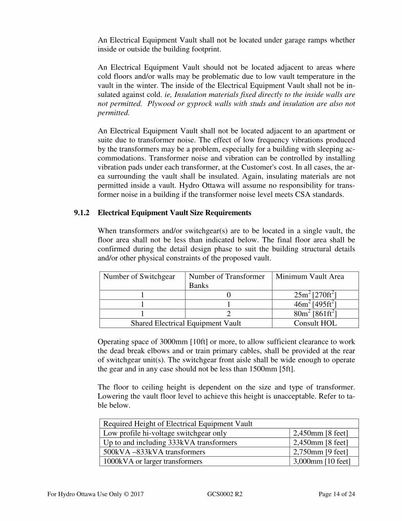
9.1.2 Electrical Equipment Vault Size Requirements
When transformers and/or switchgear(s) are to be located in a single vault, the
floor area shall not be less than indicated below. The final floor area shall be
confirmed during the detail design phase to suit the building structural details
and/or other physical constraints of the proposed vault.
Number of Switchgear Number of Transformer
Banks
Minimum Vault Area
1 0 25m2 [270ft
2]
1 1 46m2 [495ft
2]
1 2 80m2 [861ft
2]
Shared Electrical Equipment Vault Consult HOL
Operating space of 3000mm [10ft] or more, to allow sufficient clearance to work
the dead break elbows and or train primary cables, shall be provided at the rear
of switchgear unit(s). The switchgear front aisle shall be wide enough to operate
the gear and in any case should not be less than 1500mm [5ft].
The floor to ceiling height is dependent on the size and type of transformer.
Lowering the vault floor level to achieve this height is unacceptable. Refer to ta-
ble below.
Required Height of Electrical Equipment Vault
Low profile hi-voltage switchgear only 2,450mm [8 feet]
Up to and including 333kVA transformers 2,450mm [8 feet]
500kVA –833kVA transformers 2,750mm [9 feet]
1000kVA or larger transformers 3,000mm [10 feet]
For Hydro Ottawa Use Only © 2017 GCS0002 R2 Page 15 of 24
9.1.3 Personal Access Requirements
Access to an Electrical Equipment Vault shall be directly from outside the build-
ing or through the building via public area.
The Electrical Equipment Vault personnel access door shall lead directly into the
operating area and shall be located as close as possible to the transformer protec-
tive device operating position.
If access to the vault operating area is from a garage structure, then parking shall
not be permitted in front of the vault door and a "No Parking" sign must be in-
stalled on the door. Hydro Ottawa reserves the right to tow any vehicle parked in
front of the vault door at the Customer's expense.
A safe emergency exit route from the Electrical Equipment Vault operating area
and enough space to open the vault door fully must be provided.
9.1.4 Equipment Access Requirements
The equipment access route through a building must be reviewed by Hydro Ot-
tawa and sized to meet or exceed Section 9.2.4 (Personal & Equipment Doors).
The required clear height for the access route must not be compromised by any
duct, pipe or devices suspended from the ceiling along the access route. In addi-
tion, clear height along ramps must be carefully reviewed, as reduced clearances
are often encountered partway down ramps.
Indoor stairways or elevators will not be accepted as part of the equipment ac-
cess route to an Electrical Equipment Vault. Hydro Ottawa may allow the access
route to involve a properly rated freight elevator where the building has a perma-
nent backup generator supplying the freight elevator.
An access well leading directly to the Electrical Equipment Vault from the out-
side is the preferred way of moving equipment in and out of the vault if the vault
is located in the basement. A door opening into the well is required between the
vault and the well. This door shall be locked from the inside with two draw bolts.
The well shall have a drain and a 100mm [4in] curb. The well shall also be suita-
bly covered and accessible to a line truck or crane.
If access to the vault equipment area is from a garage structure, then parking
shall not be permitted in front of the vault door and a "No Parking" sign must be
installed on the door. Hydro Ottawa reserves the right to tow any vehicle parked
in front of the vault door(s) at the Customer's expense.
A lane shall only be used as part of an access route to an Electrical Equipment
Vault if it is a public lane, or if it is a private lane wholly owned by the Customer
and subject to no easements or rights-of-way. This lane shall also be maintained
in good condition and clear for line truck or crane access year round.
For Hydro Ottawa Use Only © 2017 GCS0002 R2 Page 16 of 24
9.2 Electrical Equipment Vault Construction Requirements
In addition to Hydro Ottawa requirements, the design and construction of a building Electrical
Equipment Vault shall satisfy all applicable codes and standards to include but not limited to the
Ontario Electrical Safety Code and the Ontario Building Code. Three (3) hour fire rated walls
and ceiling for vaults containing transformers, Electrical Equipment Vaults containing only
switchgear that are supplied by looped circuits or dual radial circuits must also be three (3) hour
fire rated. Walls shall be constructed of concrete block or poured concrete to a three (3) hour
rating.
HOL equipment is seismically rated. The Customer is responsible for the design and installation
of any additional seismic restraint required by the building code and/or building inspector.
In no instance will Hydro Ottawa rely on fire extinguishing systems to lower the fire separation
requirements applicable to the design and construction of a building Electrical Equipment Vault.
An Electrical Equipment Vault housing Hydro Ottawa equipment shall not be sprinklered. Refer
to Section 9.3.7 for fire detection.
The Electrical Equipment Vault construction must include a water proofing system. The pro-
posed waterproofing system must be reviewed by Hydro Ottawa. As a minimum, the vault ceil-
ing slab and walls shall be waterproofed on the outside 3,000mm [10 ft] beyond the perimeter of
the vault. The final grading of the area shall be such that water will flow away from the vault.
Equipment housekeeping pads are not allowed in Electrical Equipment Vaults,
The floor at any location within the Electrical Vault and along access routes must have adequate
strength to support Hydro Ottawa’s transformers. The maximum mass of Hydro Ottawa’s stock
vault transformers is 5000kg with an approximate area of one-square meter. Typically 3 or more
transformers installed within each Electrical vault. Please contact Hydro Ottawa should further
equipment load information be required for the Electrical Vault structural design.
The interior of the Electrical Equipment Vault shall be neatly painted with two coats of concrete
water base paint. The ceiling and sidewalls shall be painted white and the floor shall be painted
grey. A non-flammable epoxy is recommended on the floor.
The construction of the Electrical Equipment Vault must be completed and accepted by Hydro
Ottawa prior to Hydro delivering the vault equipment and/or starting work within the vault.
9.2.1 Service Duct Banks
The Service duct bank shall be painted red where they are exposed inside the
building and marked with "Danger High Voltage" every 6,100mm [20ft] or in
each individual vault.
A 100mm [4in] nominal diameter mandrel and brush approved by Hydro Ottawa
shall be pulled through each duct by the contractor in the presence of a Hydro Ot-
tawa inspector. One 6.mm [1/4in] polypropylene rope shall be left in each duct.
For Hydro Ottawa Use Only © 2017 GCS0002 R2 Page 17 of 24
The Service duct bank entrance to a building and/or vault shall be built at such an
elevation, that the conduit shall slope away from the building and be drained into
a manhole. Refer to underground duct specs for entry type and waterproofing.
9.2.2 Cable trenches
Floor cable trenches outside or within the equipment vault may be required by
Hydro Ottawa to suit the proposed equipment layout.
Cable trenches which are less than or equal to 610mm [24in] deep shall be
410mm [16in] wide. Trenches up to 1,200mm [48in] deep shall be 760mm [30in]
wide. No cable trenches shall be less than 2,450mm [8ft] long. No sharp corners
are allowed in cable trenches.
Trench cover plates shall be a minimum thickness of 10mm and a maximum mass
of 18kg. Trench cover plates are to be designed to hold the weight of the heaviest
piece of equipment and moving devices if the trench is on the path of equipment
installation or removal.
9.2.3 Cable pulling eyes
Cable-pulling eyes shall be installed at locations designated by Hydro Ottawa,
normally at the end of the cable-pulling trench opposite the duct entry point
and/or on a wall or ceiling opposite the Service duct entrance.
Cable pulling eyes must be designed to handle the following pulling tensions:
13kV Electrical Equipment Vaults 15,000lbs (6,800kg)
28kV Electrical Equipment Vaults 22,000lbs (10,000kg)
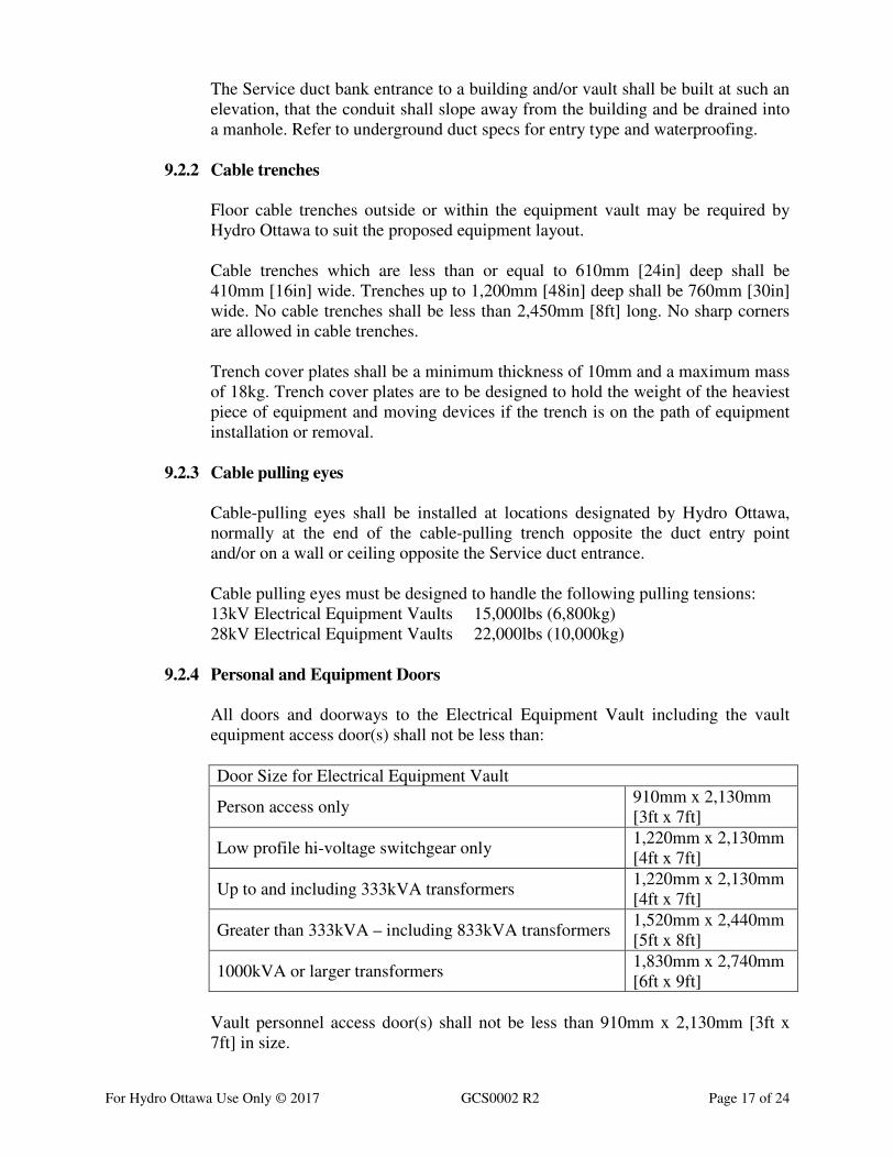
9.2.4 Personal and Equipment Doors
All doors and doorways to the Electrical Equipment Vault including the vault
equipment access door(s) shall not be less than:
Door Size for Electrical Equipment Vault
Person access only 910mm x 2,130mm
[3ft x 7ft]
Low profile hi-voltage switchgear only 1,220mm x 2,130mm
[4ft x 7ft]
Up to and including 333kVA transformers 1,220mm x 2,130mm
[4ft x 7ft]
Greater than 333kVA – including 833kVA transformers 1,520mm x 2,440mm
[5ft x 8ft]
1000kVA or larger transformers 1,830mm x 2,740mm
[6ft x 9ft]
Vault personnel access door(s) shall not be less than 910mm x 2,130mm [3ft x
7ft] in size.
For Hydro Ottawa Use Only © 2017 GCS0002 R2 Page 18 of 24
A fire door shall normally be closed and shall also be equipped with a device to
hold the door open when personnel are inside the vault.
All doors and gates shall open out from the vault and no doors shall provide ac-
cess directly into the energized area.
All door locks and operating mechanisms must be heavy-duty type and capable of
securing the door to make unauthorized entry as difficult as possible.
All double doors with internal hardware shall have a steel astragal to cover the
gap between the doors. An astragal on single door or doors with external hard-
ware shall be installed at the request of Hydro Ottawa.
Doors used for personnel access only or for both personnel and equipment access,
must be capable of being locked from outside and being operated from both inside
and outside. If a double door is used, the inactive door must be equipped with two
20mm x 254mm [3/4 “ x 10”] bolts located on the inside at the top and bottom in
addition to any internal locking mechanism.
Doors used only for equipment access shall be capable of being locked and
opened from inside the vault only. A single door shall be equipped with two
20mm x 254mm [3/4” x 10”] bolts and a double door shall be equipped with four
20mm x 254mm [3/4” x 10”] bolts located on the inside at the top and the bottom
of both doors. These bolts are in addition to any internal locking mechanism.
The final location of the equipment and/or personal access doors shall be re-
viewed and confirmed by Hydro Ottawa to suit the proposed equipment layout.
On door(s) to the outside, the hinges and locking hasps shall be designed to min-
imize their exposure to the outside weather conditions.
9.2.5 Sump
A sump shall be provided if the Electrical Equipment Vault is provided with vault
type [oil filled] transformers. The floor shall slope to a drain located in the fenced
area in front of the transformers to suit. The drain shall connect to a floor sump
located in the operating area. The sump shall be designed to hold the oil of the
largest transformer but cannot be smaller than 610mm x 610mm x 610mm [2ft x
2ft x 2ft] minimum dimensions.
As with trench cover plates; the oil sump steel cover plate shall be a minimum
thickness of 10mm and a maximum mass of 18kg. Oil sump cover plates are to be
designed to hold the weight of the heaviest piece of equipment if the sump is on
the path of equipment installation or removal.
Multiple floor drains may be required if multiple banks of transformers are in the
vault and are separated too far from each other.
For Hydro Ottawa Use Only © 2017 GCS0002 R2 Page 19 of 24
Another option is to use a steel oil tank located in a separate room below the vault
to capture the oil.
Removable curbs are required at all doorways. These curbs shall be installed and
sealed with approved caulking material after completing the electrical equipment
delivery.
9.2.6 Fence
A fencing structure is required between the operating area and the live front
equipment to restrict personnel access and protect against accidental contact. Typ-
ically the fence structure will be installed after installation of the electrical equip-
ment complete with the cable support structures and/or raceways.
The fence shall be made of chain link fabric and a minimum height of 2,130mm
[7ft] and provided with equipment access gate(s) to match the equipment access
door; refer to 9.2.4 (Personal & Equipment Doors). The gate(s) shall be equipped
with hinges and latch catch and arm or hasp lockable with a Hydro Ottawa pad-
lock.
The chain link fabric used in the fence and gate shall be an 11 gauge galvanized
steel wire with a 51mm [2”] opening. Tension shall be applied to the fabric be-
tween posts using "draw or tension" bars and the bars shall be fastened to each
post with 4 draw bar bands.
The posts should be made in two sections as follows:
• The main post shall be 2-1/2” [63.5mm] Schedule 40 galvanized pipe,
2,130mm [7ft] long with a 100mm x 76mm x 6.4mm [4” x 3” x 1/4”] plate
welded to one end.
• The top post shall be 2” [51mm] Schedule 40 galvanized pipe, minimum
910mm [3ft] long with a 76mm x 76mm x 6.4mm [3” x 3” x 1/4”] plate
welded on one end.
• The top post will slide inside the main post. The main post shall be bolted
to the floor and the top post shall be bolted to the ceiling.
The fence structure shall have no impact on the operation and maintenance of the
electrical equipment and shall allow for equipment replacement without having to
remove or disturb the fence.
9.3 Electrical Equipment Vault Support System Requirements
9.3.1 Ventilation for Electrical Equipment Vaults Containing Transformers
All Electrical Equipment Vault ventilation systems shall be built according to the
latest edition of the Ontario Electrical Safety Code and the Ontario Building
Code.

For Hydro Ottawa Use Only © 2017 GCS0002 R2 Page 20 of 24
The ventilation openings shall be located to provide ventilation across the trans-
former area from the floor, through the transformer cooling fins to the ceiling ar-
ea. Ventilation openings shall be kept away from the switchgear and exposed high
voltage equipment. In no case shall the ventilation openings be placed so that
blowing snow or rain enters the vault.
When a ventilation opening is not covered by an external duct or is in an accessi-
ble ventilation well, it shall not be located next to unshielded electrical apparatus
and shall be equipped with a two-way louver, which will prevent anything from
being pushed through.
A 13mm [1/2”] mesh screen must be mounted on the inside of all vault ventilation
openings and at the exterior of the building if ducts are used.
Fire dampers are required at the vault ventilation openings as per the Ontario
Building Code.
All equipment-controlling thermostats shall be located in the operating area.
A high temperature alarm with its own thermostat is required in all electrical
vaults containing transformers. An alarm bell and strobe must be installed outside
above or beside the door of the vault a shutoff switch is not to be included.
All mechanically operated devices must be accessible or repairable from outside
the vault or in the operating area of the vault.
Thermostats shall be set according to the following schedule:
• Dampers →18°C [65°F] OPEN ↑
• Fans → 27°C [80°F] ON ↑
• Hi Temp Alarms → 43°C [110°F] ON ↑
9.3.2 Natural Ventilation
When using natural ventilation both intake and exhaust openings must be sized to
3 sq. in / kVA [1900mm2 / kVA].
Motorized damper(s) are required, and shall be controlled by their own thermo-
stat. In vaults where more than one motorized damper is used, each damper will
require its own thermostat.
9.3.3 Forced Ventilation
Fan(s) shall be located on the exhaust side of the ventilation system.
The exhaust fan(s) shall be sized to provide 1.9 l/sec [4 cfm] of ventilation per
transformer kVA, based on the total kVA of transformation installed. The capaci-
ty of the exhaust fan(s) shall be stated on the vault drawings.
For Hydro Ottawa Use Only © 2017 GCS0002 R2 Page 21 of 24
Each fan and motorized damper(s) must be controlled by their own thermostat lo-
cated in the operating area.
9.3.4 Signs and Safety Measures
All doors, including those for equipment access, shall have signs supplied and in-
stalled by Hydro Ottawa. The signs include the Electrical Equipment Vault no-
menclature label, an electrical warning sign, and Hydro contact information.
9.3.5 Vault Lighting
Electrical Equipment Vault must be illuminated to 200-500 lux (20-50 fc). Wher-
ever possible, lights shall be mounted on the vault walls 1,980mm [6.5ft] above
the ground level or suspended from the ceiling at a height of 2,440mm [8ft]. All
lights must be LED strip fixtures and kept away from exposed high voltage
equipment to facilitate re-lamping without power disruption. A minimum of three
lights is required in a three-phase vault and two lights for a single-phase vault. In
each case, there shall be at least one light in the operating area.
The light switch shall be inside the operating area within 300mm [1ft] of the per-
sonnel access doorframe. This lighting circuit shall be on its own breaker fed from
the emergency generating system.
9.3.6 Emergency Vault Lighting
Further to the lighting in Section 9.3.5 above, each vault shall be equipped with
an automatic emergency light located in the operating area near the door. The DC
battery pack shall be located outside the vault for testing purposes if applicable.
9.3.7 Vault Fire Protection and Fire Detection
The Electrical Equipment Vault shall be totally enclosed by a fire separation of
solid masonry or concrete construction having a fire-resistance rating of not less
than 3 hours.
The Electrical Equipment Vault shall be dedicated to contain electrical equipment
only.
The fire detection system shall be designed, so that it can be maintained and test-
ed without the need to de-energize the Electrical Equipment Vault.
9.3.8 120V Receptacles
All Electrical Equipment Vaults shall contain one 120-volt duplex receptacle out-
let located in the operating area. This outlet shall be on its own breaker fed from
the emergency generating system.
For Hydro Ottawa Use Only © 2017 GCS0002 R2 Page 22 of 24
9.3.9 Cable support
The Customer shall furnish and install the primary and secondary cable support in
the vault where indicated by Hydro Ottawa. Typically the installation of the cable
support will be installed after delivery and installation of the main electrical
equipment.
9.4 Electrical Equipment Vault Grounding
Grounding shall be installed according to The Ontario Electrical Safety Code and
Hydro Ottawa proposal drawing. Where artificial electrodes are used, Hydro Ot-
tawa must check the vault ground resistance after the electrodes are installed and
before the floor is poured. For all vaults, the total equivalent resistance shall be 15
ohms or less. Please call Hydro Ottawa to have the ground resistance measured.
A ground bus loop must be mounted to the interior vault wall with a minimum of
6mm [1/4in] bolts, lock washers and nuts spaced 1,220mm [4ft] apart. This bus
shall be positioned at 150mm [6in] above the floor and spaced from the wall to al-
low the fastening of electrical connectors to the bus. This bus shall encircle the
vault to allow all necessary components to be connected to it. To reduce the effect
of circulating ground currents there is to be an open point in the ground bus at the
door to the operating area. The ground bus loop shall be made of copper and sized
according to the following:
• For vaults containing transformers 500 kVA and larger, the ground bus
loop shall not be smaller than 6mm x 51mm [1/4in x 2in] or equivalent
cross-sectional area.
• For vaults containing transformers smaller than 500 kVA, the ground bus
loop shall not be smaller than 6mm x 25.4mm [1/4in x 1in] or equivalent
cross-sectional area.
9.4.1 Connections to Ground Bus Loop
All bonding and grounding conductors shall be copper. The connections to the
ground bus or to the device being bonded / grounded shall be made using com-
pression connectors. Transformer tank bonding connections at the transformer
tank and the ground bus loop shall be visible from the operating area of the vault.
The transformer tank shall not be bonded to the transformer secondary neutral
terminal directly so that the tank does not become a path for neutral ground cur-
rents. If they are bonded together then the transformer tank shall not have a sepa-
rate bond to the vault ground bus loop.
Each bank of transformers shall have the tank bonds and the neutral ground (star
point) connected to the ground bus loop within a 2,000mm space (aka Transform-
er Ground Zone). This is to:
• To minimize the length of parallel ground paths.
For Hydro Ottawa Use Only © 2017 GCS0002 R2 Page 23 of 24
• To minimize the length of circulating ground currents which cause addi-
tional equipment heating and EMFs that affect the occupancy and electri-
cal equipment in adjacent rooms.
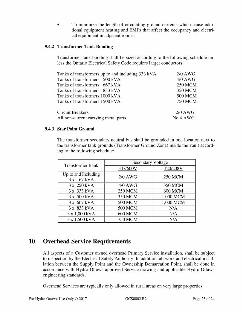
9.4.2 Transformer Tank Bonding
Transformer tank bonding shall be sized according to the following schedule un-
less the Ontario Electrical Safety Code requires larger conductors.
Tanks of transformers up to and including 333 kVA 2/0 AWG
Tanks of transformers 500 kVA 4/0 AWG
Tanks of transformers 667 kVA 250 MCM
Tanks of transformers 833 kVA 350 MCM
Tanks of transformers 1000 kVA 500 MCM
Tanks of transformers 1500 kVA 750 MCM
Circuit Breakers 2/0 AWG
All non-current carrying metal parts No.4 AWG
9.4.3 Star Point Ground
The transformer secondary neutral bus shall be grounded in one location next to
the transformer tank grounds (Transformer Ground Zone) inside the vault accord-
ing to the following schedule:
Transformer Bank Secondary Voltage
347/600V 120/208V
Up to and Including
3 x 167 kVA 2/0 AWG 250 MCM
3 x 250 kVA 4/0 AWG 350 MCM
3 x 333 kVA 250 MCM 600 MCM
3 x 500 kVA 350 MCM 1,000 MCM
3 x 667 kVA 500 MCM 1,000 MCM
3 x 833 kVA 500 MCM N/A
3 x 1,000 kVA 600 MCM N/A
3 x 1,500 kVA 750 MCM N/A
10 Overhead Service Requirements
All aspects of a Customer owned overhead Primary Service installation, shall be subject
to inspection by the Electrical Safety Authority. In addition, all work and electrical instal-
lation between the Supply Point and the Ownership Demarcation Point, shall be done in
accordance with Hydro Ottawa approved Service drawing and applicable Hydro Ottawa
engineering standards.
Overhead Services are typically only allowed in rural areas on very large properties.
For Hydro Ottawa Use Only © 2017 GCS0002 R2 Page 24 of 24
(ie, farms or large government / industrial properties). Multi-pole structures (pole stands)
for switching and/or transformers are not permitted whether for temporary or permanent
use. Refer to HOL Conditions of Service section 3.3.
Hydro Ottawa will supply and install primary conductor from the supply pole to the first
pole inside the Customer’s property including an in-line fused disconnect at the Custom-
er’s pole. The electrical Ownership Demarcation Point for overhead Services is at the in-
line fused cutout. Refer to ECG0005 fig 1 and ECG0009 fig 1. The first pole must be lo-
cated just inside the Customer’s property.
A gang operated overhead load-break switch is required on the first Customer pole rather
than in-line switches in the following circumstances:
• If the Customer’s load is to be greater than 300kVA.
• If there is greater than 10kVA of imbedded generation or energy resource
facility (ERF).
• Customer is using a delta wired transformer.
• If there is a possibility of Ferroresonance.
The minimum in-line pole with an overhead transformer shall be 45ft Class 3.
New permanent structures (that are ‘normally’ occupied such as houses, garages, build-
ings, buildings with balconies, mobile trailer homes) shall not be located within the safe
limits of approach (for <46kV, it is 3 metres from the maximum outward conductor
swing) plus an additional 2 metres for building maintenance (such as painting, roofing,
window washing, brick pointing); this would mean a minimum of 5 metre radial separa-
tion from the closest primary phase conductor. In addition, every attempt shall be made to
keep existing buildings at least 2 metres horizontally outside of the closest primary phase
conductor with respect to the vertical plane (from the ground to the primary phase con-
ductor). On an individual (case-by-case) basis, portable and temporary (less than 1 year)
structures such as garden sheds < 100 ft-sq and construction trailers may be installed di-
rectly under primary conductors where there is sufficient height (>3 m vertically from
primary plus 2m for a person standing on top of the temporary structure) and the structure
is grounded (minimum of <25 ohms with a #4 AWG Copper conductor to a 3 meter
ground rod) although a reasonable attempt should be made to avoid such arrangements.
The maximum size of a pole transformer for both single phase and three phase (banked)
applications is 100kVA.
Grounding at the time of installation must measure less than 25 ohms. Please call Hydro
Ottawa to have the ground resistance measured.
Primary overhead metering is allowed when the Customer owns their own transformer
and cannot meet Hydro Ottawa standard transformer losses. Refer to MCS0045 for Pri-
mary Metering Pole construction. 44kV overhead Services require primary metering.