Embed Size (px)
Citation preview
1
GB/US . . . . .DH .2000
Vers . .1 .00
© G
uldm
ann
GB
/US
-897
/08/
08 •
# 9
0066
2
2
© G
uldm
ann
GB
/US
-897
/08/
08 •
# 9
0066
2
© G
uldm
ann
GB
/US
-897
/08/
08 •
# 9
0066
2
© G
uldm
ann
GB
/US
-897
/08/
08 •
# 9
0066
2
© G
uldm
ann
GB
/US
-897
/08/
08 •
# 9
0066
2
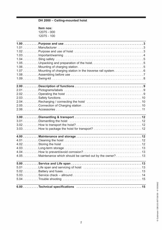
. DH .2000 .– .Ceiling-mounted .hoist
Item .nos:12075 - 00012075 - 100
1 .00 . . . . . . . . . .Purpose .and .use . . . . . . . . . . . . . . . . . . . . . . . . . . . . . . . . . . . . . . . . . . . . . . . 31.01 . . . . . . . . . Manufacturer . . . . . . . . . . . . . . . . . . . . . . . . . . . . . . . . . . . . . . . . . . . . . . . . . . 31.02 . . . . . . . . . Purpose and use of hoist . . . . . . . . . . . . . . . . . . . . . . . . . . . . . . . . . . . . . . . . 31.03 . . . . . . . . . Important/warning . . . . . . . . . . . . . . . . . . . . . . . . . . . . . . . . . . . . . . . . . . . . . . 41.04 . . . . . . . . . Sling safety . . . . . . . . . . . . . . . . . . . . . . . . . . . . . . . . . . . . . . . . . . . . . . . . . . . 51.05 . . . . . . . . . Unpacking and preparation of the hoist . . . . . . . . . . . . . . . . . . . . . . . . . . . . . . 51.06 . . . . . . . . . Mounting of charging station . . . . . . . . . . . . . . . . . . . . . . . . . . . . . . . . . . . . . . 51.07 . . . . . . . . . Mounting of charging station in the traverse rail system . . . . . . . . . . . . . . . . . 61.08 . . . . . . . . . Assembling before use . . . . . . . . . . . . . . . . . . . . . . . . . . . . . . . . . . . . . . . . . . 71.09 . . . . . . . . . Swing-kit . . . . . . . . . . . . . . . . . . . . . . . . . . . . . . . . . . . . . . . . . . . . . . . . . . . . . 8
2 .00 . . . . . . . . . .Description .of .functions . . . . . . . . . . . . . . . . . . . . . . . . . . . . . . . . . . . . . . . . . 92.01 . . . . . . . . . Pictograms/labels . . . . . . . . . . . . . . . . . . . . . . . . . . . . . . . . . . . . . . . . . . . . . . 92.02 . . . . . . . . . Operating the hoist . . . . . . . . . . . . . . . . . . . . . . . . . . . . . . . . . . . . . . . . . . . . . 92.03 . . . . . . . . . Safety functions . . . . . . . . . . . . . . . . . . . . . . . . . . . . . . . . . . . . . . . . . . . . . . . 102.04 . . . . . . . . . Recharging / connecting the hoist . . . . . . . . . . . . . . . . . . . . . . . . . . . . . . . . 102.05 . . . . . . . . . Connection of Charging station . . . . . . . . . . . . . . . . . . . . . . . . . . . . . . . . . . . 102.06 . . . . . . . . . Accessories . . . . . . . . . . . . . . . . . . . . . . . . . . . . . . . . . . . . . . . . . . . . . . . . . . 11
3 .00 . . . . . . . . . .Dismantling .& .transport . . . . . . . . . . . . . . . . . . . . . . . . . . . . . . . . . . . . . . . . 123.01 . . . . . . . . . Dismantling the hoist . . . . . . . . . . . . . . . . . . . . . . . . . . . . . . . . . . . . . . . . . . 123.02 . . . . . . . . . How to transport the hoist? . . . . . . . . . . . . . . . . . . . . . . . . . . . . . . . . . . . . . . 123.03 . . . . . . . . . How to package the hoist for transport? . . . . . . . . . . . . . . . . . . . . . . . . . . . . 12
4 .00 . . . . . . . . . .Maintenance .and .storage . . . . . . . . . . . . . . . . . . . . . . . . . . . . . . . . . . . . . . . . . . . . . . . . . . . . . . . . . . . . . . . . . . . . . . . . . . . . 124.01 . . . . . . . . . Cleaning the hoist . . . . . . . . . . . . . . . . . . . . . . . . . . . . . . . . . . . . . . . . . . . . . 124.02 . . . . . . . . . Storing the hoist . . . . . . . . . . . . . . . . . . . . . . . . . . . . . . . . . . . . . . . . . . . . . . 124.03 . . . . . . . . . Long-term storage . . . . . . . . . . . . . . . . . . . . . . . . . . . . . . . . . . . . . . . . . . . . . 134.04 . . . . . . . . . How to prevent/avoid corrosion? . . . . . . . . . . . . . . . . . . . . . . . . . . . . . . . . . . 134.05 . . . . . . . . . Maintenance which should be carried out by the owner? . . . . . . . . . . . . . . . 13
5 .00 . . . . . . . . . .Service .and .Life .span . . . . . . . . . . . . . . . . . . . . . . . . . . . . . . . . . . . . . . . . . . . 135.01 . . . . . . . . . Life span and servicing of hoist . . . . . . . . . . . . . . . . . . . . . . . . . . . . . . . . . . 135.02 . . . . . . . . . Battery and fuses . . . . . . . . . . . . . . . . . . . . . . . . . . . . . . . . . . . . . . . . . . . . . . 135.03 . . . . . . . . . Service check – allround . . . . . . . . . . . . . . . . . . . . . . . . . . . . . . . . . . . . . . . . 145.04 . . . . . . . . . Trouble shooting . . . . . . . . . . . . . . . . . . . . . . . . . . . . . . . . . . . . . . . . . . . . . . 15
6 .00 . . . . . . . . . . Technical .specifications . . . . . . . . . . . . . . . . . . . . . . . . . . . . . . . . . . . . . . . . 15
3
1 .00 . Purpose .and .use
1 .01 . ManufacturerV. Guldmann A/S.Graham Bells Vej 23A DK – 8200 Århus NTel. + 45 8741 3100Fax + 45 8741 3131
1 .02 . Purpose .and .use .of .hoist .
PurposeDH 2000 is a lifting module of the Guldmann Ceiling-Mounted Lifting Systems. DH 2000 is suitable in all Guldmann rail systems, both single track, room-covering, and combined rail systems.DH 2000 is developped for use in private homes, insitutions, hospitals, riding schools, and swimming pools, where it offers full flexibility for lifting, transferring, and transporting of elderly and disabled persons.
RequirementsThe instruction that Guldmann offers all custumers when ordering a DH 2000, has been received.When a hoist is used in an institution or in the home care service, the assumption is that it will be operated by qualified staff.Use slings with 4-6 lifting straps designed for use with hooks of min. Ø 8 mm.
Lifting .to .and .from .a .sitting .positionWhen lifting from e.g. a wheelchair, move DH 2000 towards the person to be lifted. The lifting hanger should be level with the chest and positioned above the middle of the thigh.Position lifting hanger parallel to the user’s shoulders. Now fit the lifting sling to the lifting hanger. For instructions on how to fit the sling, see the section entitled “Fitting the sling”.
Lifting .to .and .from .a .lying .position .in .bedThe lifting hanger is placed right over the person. The lifting hanger should be parallel with the person’s shoulders. Now fit the lifting sling to the lifting hanger. For instructions on how to fit the sling, see section entitled “Fitting the sling”.
Working .with .DH .2000As the DH 2000 does not require any special space or power consumption and as it is easy to move around in the rail system, only the user’s functional level and the carer’s working technique need to be considered.Lift the user claer of the surface and continue transferring at this height.
© G
uldm
ann
GB
/US
-897
/08/
08 •
# 9
0066
2
© G
uldm
ann
GB
/US
-897
/08/
08 •
# 9
0066
2
© G
uldm
ann
GB
/US
-897
/08/
08 •
# 9
0066
2
© G
uldm
ann
GB
/US
-897
/08/
08 •
# 9
0066
2
4
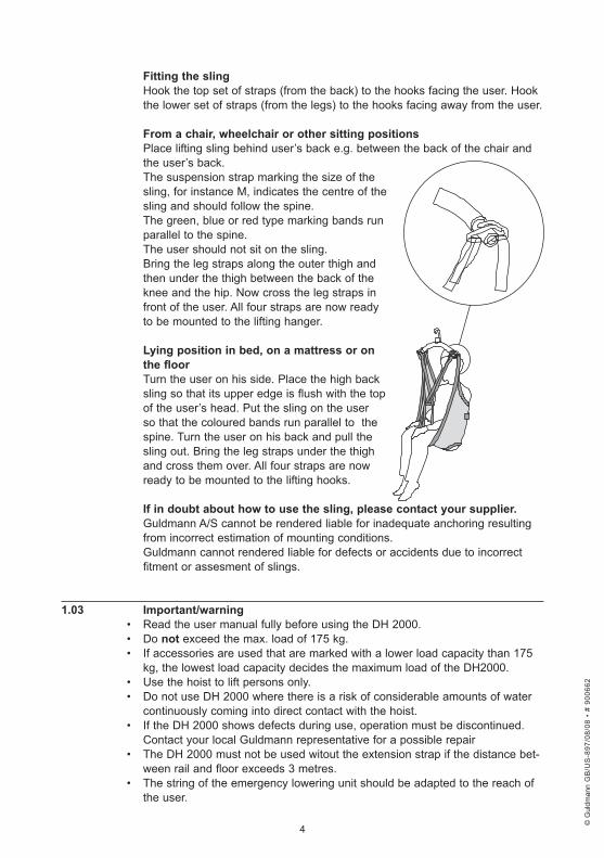
Fitting .the .slingHook the top set of straps (from the back) to the hooks facing the user. Hook the lower set of straps (from the legs) to the hooks facing away from the user.
From .a .chair, .wheelchair .or .other .sitting .positionsPlace lifting sling behind user’s back e.g. between the back of the chair and the user’s back.The suspension strap marking the size of the sling, for instance M, indicates the centre of the sling and should follow the spine.The green, blue or red type marking bands run parallel to the spine.The user should not sit on the sling.Bring the leg straps along the outer thigh and then under the thigh between the back of the knee and the hip. Now cross the leg straps in front of the user. All four straps are now ready to be mounted to the lifting hanger.
Lying .position .in .bed, .on .a .mattress .or .on .the .floorTurn the user on his side. Place the high back sling so that its upper edge is flush with the top of the user’s head. Put the sling on the user so that the coloured bands run parallel to the spine. Turn the user on his back and pull the sling out. Bring the leg straps under the thigh and cross them over. All four straps are now ready to be mounted to the lifting hooks.
If .in .doubt .about .how .to .use .the .sling, .please .contact .your .supplier .Guldmann A/S cannot be rendered liable for inadequate anchoring resulting from incorrect estimation of mounting conditions.Guldmann cannot rendered liable for defects or accidents due to incorrect fitment or assesment of slings.
1 .03 . Important/warning• Read the user manual fully before using the DH 2000.• Do not exceed the max. load of 175 kg.• If accessories are used that are marked with a lower load capacity than 175
kg, the lowest load capacity decides the maximum load of the DH2000.• Use the hoist to lift persons only.• Do not use DH 2000 where there is a risk of considerable amounts of water
continuously coming into direct contact with the hoist.• If the DH 2000 shows defects during use, operation must be discontinued.
Contact your local Guldmann representative for a possible repair• The DH 2000 must not be used witout the extension strap if the distance bet-
ween rail and floor exceeds 3 metres.• The string of the emergency lowering unit should be adapted to the reach of
the user.
© G
uldm
ann
GB
/US
-897
/08/
08 •
# 9
0066
2
© G
uldm
ann
GB
/US
-897
/08/
08 •
# 9
0066
2
© G
uldm
ann
GB
/US
-897
/08/
08 •
# 9
0066
2
© G
uldm
ann
GB
/US
-897
/08/
08 •
# 9
0066
2
5
1 .04 . Sling .safetyOnly CE-marked slings with a lifting capacity corresponding to or higher than the lifting capacity of the DH 2000 are to be used.The lifting straps must be suitable for hooks with a diameter of 8 mm. The lif-ting straps must be designed for use with a four-point horizontal lifting hanger.Guldmann cannot be rendered liable for defects and accidents, due to use of a sling manufactured by others.
1 .05 . Unpacking .and .preparation .of .the .hoist
Visual .check .of .hoist:Should the packaging be damaged on receipt, each part of the hoist must be carefully examined for visible defects or deficiencies. In case of suspected damage, do not use the hoist until authorised by qualified service staff or the Guldmann Service Team.
Parts .list:
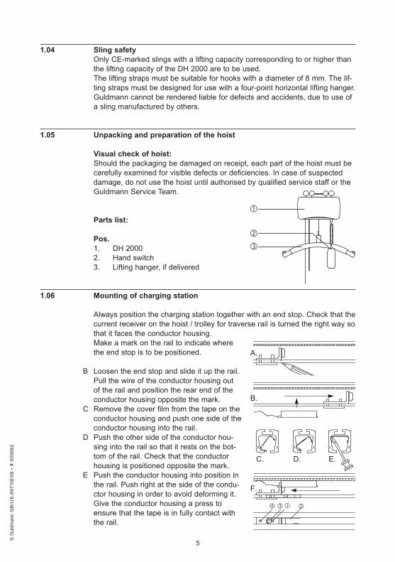
Pos .1. DH 20002. Hand switch3. Lifting hanger, if delivered
1 .06 . Mounting .of .charging .station
Always position the charging station together with an end stop. Check that the current receiver on the hoist / trolley for traverse rail is turned the right way so that it faces the conductor housing.Make a mark on the rail to indicate where the end stop is to be positioned.
B Loosen the end stop and slide it up the rail. Pull the wire of the conductor housing out of the rail and position the rear end of the conductor housing opposite the mark.
C Remove the cover film from the tape on the conductor housing and push one side of the conductor housing into the rail.
D Push the other side of the conductor hou-sing into the rail so that it rests on the bot-tom of the rail. Check that the conductor housing is positioned opposite the mark.
E Push the conductor housing into position in the rail. Push right at the side of the condu-ctor housing in order to avoid deforming it.
Give the conductor housing a press to ensure that the tape is in fully contact with the rail.
�
��
E.D.C.
F.
B.
A.
����
© G
uldm
ann
GB
/US
-897
/08/
08 •
# 9
0066
2
© G
uldm
ann
GB
/US
-897
/08/
08 •
# 9
0066
2
© G
uldm
ann
GB
/US
-897
/08/
08 •
# 9
0066
2
© G
uldm
ann
GB
/US
-897
/08/
08 •
# 9
0066
2
6
Slide the end stop back to the mark. Unscrew the screw (1) next to the rub-ber knob of the end stop and fit the spring retainer (2) into the opening of the rail undeneath the end stop. The opening of the spring retainer must face the hoist. The foam rubber disc (3) must be positioned at the bottom end of the spring retainer (4) behind the screw. Tighten the end stop.Connect the conductor housing to the charger and check the function.The positioning of the conductor housing could be marked by means of the enclosed labels with charging symbols.
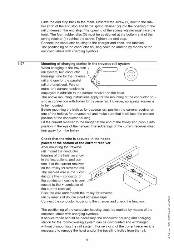
1 .07 . Mounting .of .charging .station .in .the .traverse .rail .systemWhen charging in the traverse rail system, two conductor housings, one for the traverse rail and one for the parallel rail are employed. Further-more, one current receiver is employed in addition to the current receiver on the hoist.The above mounting instructions apply for the mounting of the conductor hou-sing in connection with trolley for traverse rail. However, no spring retainer is to be mounted.Before mounting the trolleys for traverse rail, position the current receiver on one of the trolleys for traverse rail and make sure that it will face the chosen position of the conductor housing.Fit the current receiver to the hanger at the end of the trolley and push it into position in the eye of the hanger. The solderings of the current receiver must turn away from the trolley.
Check .that .the .wire .is .secured .in .the .hooks . .placed .at .the .bottom .of .the .current .receiverAfter mounting the traverse rail, mount the conductor housing of the hoist as shown in the instructions, and con-nect it to the current receiver on the trolley for traverse rail. The marked wire is the + con-ductor. (The + conductor of the conductor housing is con-nected to the + conductor of the current receiver)Stick the wire underneath the trolley for traverse rail by means of double sided adhesive tape.Connect the conductor housing to the charger and check the function.
The positioning of the conductor housing could be marked by means of the enclosed labels with charging symbols.If service/repair should be necessary, the conductor housing and charging station for the room-covering system can be dismounted and exchanged without dismounting the rail system. For servicing of the current receiver it is necessary to remove the hoist and/or the travelling trolley from the rail.
© G
uldm
ann
GB
/US
-897
/08/
08 •
# 9
0066
2
© G
uldm
ann
GB
/US
-897
/08/
08 •
# 9
0066
2
© G
uldm
ann
GB
/US
-897
/08/
08 •
# 9
0066
2
© G
uldm
ann
GB
/US
-897
/08/
08 •
# 9
0066
2
7
����
�
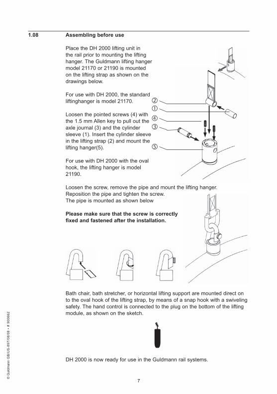
1 .08 . Assembling .before .use .
Place the DH 2000 lifting unit in the rail prior to mounting the lifting hanger. The Guldmann lifting hanger model 21170 or 21190 is mounted on the lifting strap as shown on the drawings below.
For use with DH 2000, the standard liftinghanger is model 21170.
Loosen the pointed screws (4) with the 1.5 mm Allen key to pull out the axle journal (3) and the cylinder sleeve (1). Insert the cylinder sleeve in the lifting strap (2) and mount the lifting hanger(5).
For use with DH 2000 with the oval hook, the lifting hanger is model 21190.
Loosen the screw, remove the pipe and mount the lifting hanger.Reposition the pipe and tighten the screw.The pipe is mounted as shown below
Please .make .sure .that .the .screw .is .correctly .fixed .and .fastened .after .the .installation .
Bath chair, bath stretcher, or horizontal lifting support are mounted direct on to the oval hook of the lifting strap, by means of a snap hook with a swiveling safety. The hand control is connected to the plug on the bottom of the lifting module, as shown on the sketch.
DH 2000 is now ready for use in the Guldmann rail systems.
© G
uldm
ann
GB
/US
-897
/08/
08 •
# 9
0066
2
© G
uldm
ann
GB
/US
-897
/08/
08 •
# 9
0066
2
© G
uldm
ann
GB
/US
-897
/08/
08 •
# 9
0066
2
© G
uldm
ann
GB
/US
-897
/08/
08 •
# 9
0066
2
8
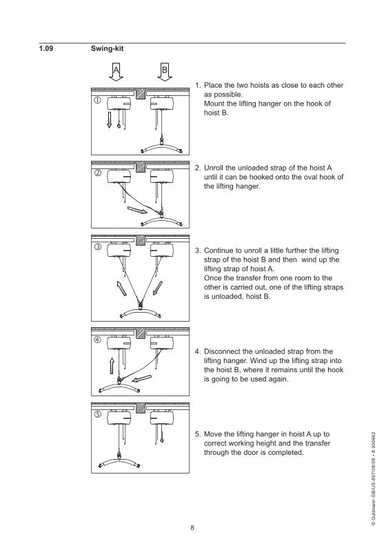
1 .09 . Swing-kit
1. Place the two hoists as close to each other as possible. Mount the lifting hanger on the hook of hoist B.
2. Unroll the unloaded strap of the hoist A until it can be hooked onto the oval hook of the lifting hanger.
3. Continue to unroll a little further the lifting strap of the hoist B and then wind up the lifting strap of hoist A. Once the transfer from one room to the other is carried out, one of the lifting straps is unloaded, hoist B.
4. Disconnect the unloaded strap from the lifting hanger. Wind up the lifting strap into the hoist B, where it remains until the hook is going to be used again.
5. Move the lifting hanger in hoist A up to correct working height and the transfer through the door is completed.
�
�
�
�
�
A B
© G
uldm
ann
GB
/US
-897
/08/
08 •
# 9
0066
2
© G
uldm
ann
GB
/US
-897
/08/
08 •
# 9
0066
2
© G
uldm
ann
GB
/US
-897
/08/
08 •
# 9
0066
2
© G
uldm
ann
GB
/US
-897
/08/
08 •
# 9
0066
2
9
2 .00 . Description .of .functions
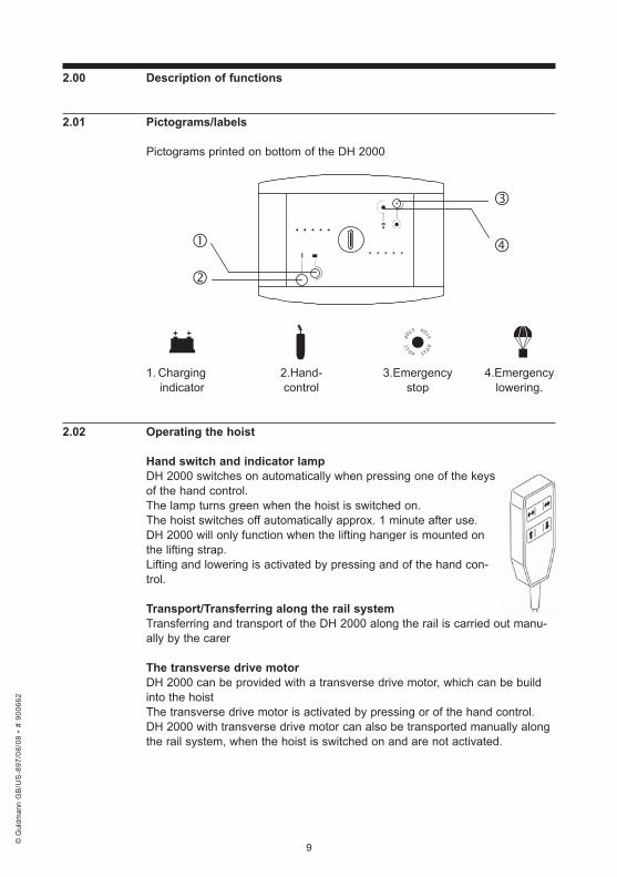
2 .01 . Pictograms/labels .
Pictograms printed on bottom of the DH 2000
1. Charging 2.Hand- 3.Emergency 4.Emergency indicator control stop lowering.
2 .02 . Operating .the .hoist
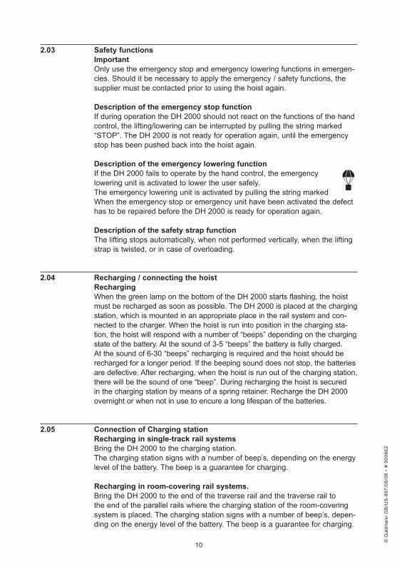
Hand .switch .and .indicator .lampDH 2000 switches on automatically when pressing one of the keys of the hand control.The lamp turns green when the hoist is switched on.The hoist switches off automatically approx. 1 minute after use.DH 2000 will only function when the lifting hanger is mounted on the lifting strap.Lifting and lowering is activated by pressing and of the hand con-trol.
Transport/Transferring .along .the .rail .systemTransferring and transport of the DH 2000 along the rail is carried out manu-ally by the carer
The .transverse .drive .motorDH 2000 can be provided with a transverse drive motor, which can be build into the hoistThe transverse drive motor is activated by pressing or of the hand control.DH 2000 with transverse drive motor can also be transported manually along the rail system, when the hoist is switched on and are not activated.
S T O P
S T O
P S T O P
S
T O P
S T O P
S T
O P S T O
P S
T
O P
© G
uldm
ann
GB
/US
-897
/08/
08 •
# 9
0066
2
© G
uldm
ann
GB
/US
-897
/08/
08 •
# 9
0066
2
© G
uldm
ann
GB
/US
-897
/08/
08 •
# 9
0066
2
© G
uldm
ann
GB
/US
-897
/08/
08 •
# 9
0066
2
10
2 .03 . Safety .functionsImportantOnly use the emergency stop and emergency lowering functions in emergen-cies. Should it be necessary to apply the emergency / safety functions, the supplier must be contacted prior to using the hoist again.
Description .of .the .emergency .stop .functionIf during operation the DH 2000 should not react on the functions of the hand control, the lifting/lowering can be interrupted by pulling the string marked “STOP”. The DH 2000 is not ready for operation again, until the emergency stop has been pushed back into the hoist again.
Description .of .the .emergency .lowering .functionIf the DH 2000 fails to operate by the hand control, the emergency lowering unit is activated to lower the user safely.The emergency lowering unit is activated by pulling the string markedWhen the emergency stop or emergency unit have been activated the defect has to be repaired before the DH 2000 is ready for operation again.
Description .of .the .safety .strap .functionThe lifting stops automatically, when not performed vertically, when the lifting strap is twisted, or in case of overloading.
2 .04 . Recharging ./ .connecting .the .hoist .RechargingWhen the green lamp on the bottom of the DH 2000 starts flashing, the hoist must be recharged as soon as possible. The DH 2000 is placed at the charging station, which is mounted in an appropriate place in the rail system and con-nected to the charger. When the hoist is run into position in the charging sta-tion, the hoist will respond with a number of “beeps” depending on the charging state of the battery. At the sound of 3-5 “beeps” the battery is fully charged. At the sound of 6-30 “beeps” recharging is required and the hoist should be recharged for a longer period. If the beeping sound does not stop, the batteries are defective. After recharging, when the hoist is run out of the charging station, there will be the sound of one “beep”. During recharging the hoist is secured in the charging station by means of a spring retainer. Recharge the DH 2000 overnight or when not in use to encure a long lifespan of the batteries.
2 .05 . Connection .of .Charging .stationRecharging .in .single-track .rail .systemsBring the DH 2000 to the charging station.The charging station signs with a number of beep’s, depending on the energy level of the battery. The beep is a guarantee for charging.
Recharging .in .room-covering .rail .systems .Bring the DH 2000 to the end of the traverse rail and the traverse rail to the end of the parallel rails where the charging station of the room-covering system is placed. The charging station signs with a number of beep’s, depen-ding on the energy level of the battery. The beep is a guarantee for charging.
© G
uldm
ann
GB
/US
-897
/08/
08 •
# 9
0066
2
© G
uldm
ann
GB
/US
-897
/08/
08 •
# 9
0066
2
© G
uldm
ann
GB
/US
-897
/08/
08 •
# 9
0066
2
© G
uldm
ann
GB
/US
-897
/08/
08 •
# 9
0066
2
11
2 .06 . Accessories
Transverse .drive .motorThe transverse drive motor makes the hoist fully automatic. It is built into the DH 2000 without changing the outer dimensions and the visual impression of the hoist.When the hoist is provided with the drive motor, the spped is gradually increased to 8 metres / minute to ensure a smooth up-start.
IR .remote .control .The IR remote control is often used with the hoist with transverse drive motor, enabling the user to “ call “ the hoist and thus to a certain degree be indepen-dent of the carer.
Important!When the user is independent, the IR remote control sender should be attached to the user, so that it will always be within the reach.
Lifting .SlingsPlease ask the distributor for a special leaflet on Lifting Slings.
Extension .strapThis is used if the distance between rail and floor exceeds 3 metres, and is ordered separately. If E.G. the distance is 3.5 metres between rail and floor you should order an extension strap of 0.5 metres length.
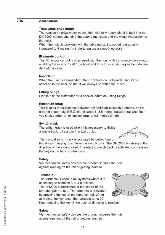
Switch .trackThe switch track is used when it is necessary to divide a single track rail system into two tracks.
The manual switch track is activated by pulling one of the strings hanging down from the switch track. The DH 2000 is driving in the direction of the string pulled. The electric switch track is activated by pressing the key on the hand control once.
SafetyVia mechanical safety devices the product secures the hoistagainst running off the rail or getting jammed.
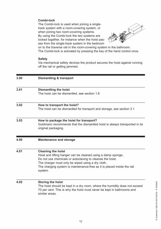
TurntableThe turntable is used in rail systems where it is necessary to combine 3 or 4 directions.The DH2000 is positioned in the centre of the turntable prior to use. The turntable is activated by pressing the key of the hand control. When activating the key once, the turntable turns 90°. Keep pressing the key till the desired direction is reached.
SafetyVia mechanical safety devices the product secures the hoistagainst running off the rail or getting jammed.
© G
uldm
ann
GB
/US
-897
/08/
08 •
# 9
0066
2
© G
uldm
ann
GB
/US
-897
/08/
08 •
# 9
0066
2
© G
uldm
ann
GB
/US
-897
/08/
08 •
# 9
0066
2
© G
uldm
ann
GB
/US
-897
/08/
08 •
# 9
0066
2
12
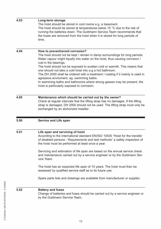
Combi-lockThe Combi-lock is used when joining a single-track system with a room-covering system, or when joining two room-covering systems.By using the Combi-lock the two systems are locked together, for instance when the hoist pas-ses from the single-track system in the bedroom on to the traverse rail in the room-covering system in the bathroom.The Combi-lock is activated by pressing the key of the hand control once.
SafetyVia mechanical safety devices the product secures the hoist against running off the rail or getting jammed.
3 .00 . Dismantling .& .transport
3 .01 . Dismantling .the .hoist .The hoist can be dismantled, see section 1.8
3 .02 . How .to .transport .the .hoist?The hoist can be dismantled for transport and storage, see section 3.1
3 .03 . How .to .package .the .hoist .for .transport?Guldmann recommends that the dismantled hoist is always transported in its original packaging.
4 .00 . Maintenance .and .storage .
4 .01 . Cleaning .the .hoist .Hoist and lifting hanger can be cleaned using a damp sponge..Do not use chemicals or autoclaving to cleanse the hoist.The charger must only be wiped using a dry cloth.The charging system is maintenance-free as it is placed inside the rail system.
4 .02 . Storing .the .hoist .The hoist should be kept in a dry room, where the humidity does not exceed 70 per cent. This is why the hoist must never be kept in bathrooms and similar areas.
© G
uldm
ann
GB
/US
-897
/08/
08 •
# 9
0066
2
© G
uldm
ann
GB
/US
-897
/08/
08 •
# 9
0066
2
© G
uldm
ann
GB
/US
-897
/08/
08 •
# 9
0066
2
© G
uldm
ann
GB
/US
-897
/08/
08 •
# 9
0066
2
13
4 .03 . Long-term .storageThe hoist should be stored in cool rooms e.g. a basement.The hoist should be stored at temperatures below 15 °C due to the risk of running the batteries down. The Guldmann Service Team recommends that the fuses are removed from the hoist when it is stored for long periods of time.
4 .04 . How .to .prevent/avoid .corrosion?The hoist should not be kept / remain in damp surroundings for long periods. Water vapour might liquefy into water on the hoist, thus causing corrosion / rust in the bearings.The hoist should not be exposed to sudden cold or warmth. This means that one should not take a cold hoist into e.g a hot bathroom.The DH 2000 shall be ordered with a treatment / coating if it mainly is used in agressive enviroment, eg. swimming baths.In swimming baths and bathrooms where strong gasses may be present, the hoist is particularly exposed to corrosion.
4 .05 . Maintenance .which .should .be .carried .out .by .the .owner?Check at regular intervals that the lifting strap has no damages. If the lifting strap is damaged, DH 2000 should not be used. The lifting strap must only be exchanged by an atuhorized installer.
5 .00 . Service .and .Life .span .
5 .01 . Life .span .and .servicing .of .hoist .According to the international standard EN/ISO 10535 “Hoist for the transfer of disabled persons - Requirements and test methods” a safety inspection of the hoist must be performed at least once a year.
Servicing and estimation of life span are based on the annual service check and maintenance carried out by a service engineer or by the Guldmann Ser-vice Team.
The hoist has an expected life span of 15 years. The hoist must then be assessed by qualified service staff as to its future use.
Spare parts lists and drawings are available from manufacturer or supplier.
5 .02 . Battery .and .fusesChange of batteries and fuses should be carried out by a service engineer or by the Guldmann Service Team.
© G
uldm
ann
GB
/US
-897
/08/
08 •
# 9
0066
2
© G
uldm
ann
GB
/US
-897
/08/
08 •
# 9
0066
2
© G
uldm
ann
GB
/US
-897
/08/
08 •
# 9
0066
2
© G
uldm
ann
GB
/US
-897
/08/
08 •
# 9
0066
2
14
5 .03 . Service .check .– .allroundDuring the inspection a service report shall be made, describing what has been checked and exchanged.Worn or defective parts shall be replaced by new spareparts from V. Guldmann A/S.
1 . Visual .check .of .the .product• Check the product for wear and tear• Check the product for any deformity• Check that the product does not show any other dificiencies.
2 . Test .of .the .product, .as .during .normal .use• Check all functions on the product, with and without load,• ( eg. Up, down, forward, backward, out and in ).• Check the emergency lowering is operational.• Check the emergency stop is operational.• Check the charging indicator is operational.
3 . Dismantle .the .cover/fence
4 . Check .the .electrical .condition .of .the .products• Check the batteries and measure the:• Input / Voltage• Output / Voltage• Check electrical functions and signals• Check all wirings for errors and defects• Check wire lead-ins• Check all possible conections, plugs etc.
5 . Check .the .mechanical .condition .oft .the .product• Clean the product for dirt and other impurities• Inspect and evaluate the vital parts of the product• Exchange defective and worn• Grease the product
6 . Mount .the .cover/fence
7 . Point .1 .2 .is .carried .out .one .more .time .as .a .control .function
8 . Have .new .errors .or .problems .arisen .in .point .7?• If new problems have arisen, go back to point 3• If no problems have arisen, finish the inspection.
9 . When .a .service .inspection .including .service .work .or .exchange . .of .components .has .taken .place, .the .final .check .should .comprise . .a .weight .test .with .the .product’s .nominal .load
If the DH 2000 has been silicone-coated for use in wet environment, this coa-ting must be renewed if it shows sign of drying.
© G
uldm
ann
GB
/US
-897
/08/
08 •
# 9
0066
2
© G
uldm
ann
GB
/US
-897
/08/
08 •
# 9
0066
2
© G
uldm
ann
GB
/US
-897
/08/
08 •
# 9
0066
2
© G
uldm
ann
GB
/US
-897
/08/
08 •
# 9
0066
2
15
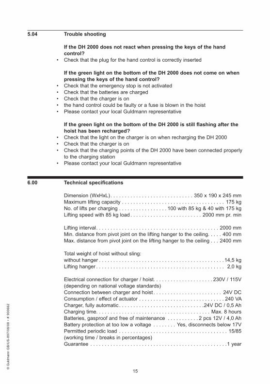
5 .04 . Trouble .shooting
If .the .DH .2000 .does .not .react .when .pressing .the .keys .of .the .hand . .control?
• Check that the plug for the hand control is correctly inserted
If .the .green .light .on .the .bottom .of .the .DH .2000 .does .not .come .on .when .pressing .the .keys .of .the .hand .control?
• Check that the emergency stop is not activated• Check that the batteries are charged• Check that the charger is on• the hand control could be faulty or a fuse is blown in the hoist• Please contact your local Guldmann representative
If .the .green .light .on .the .bottom .of .the .DH .2000 .is .still .flashing .after .the .hoist .has .been .recharged?
• Check that the light on the charger is on when recharging the DH 2000• Check that the charger is on• Check that the charging points of the DH 2000 have been connected properly
to the charging station• Please contact your local Guldmann representative
6 .00 . Technical .specifications .
Dimension (WxHxL) . . . . . . . . . . . . . . . . . . . . . . . . . . . . . 350 x 190 x 245 mmMaximum lifting capacity . . . . . . . . . . . . . . . . . . . . . . . . . . . . . . . . . . . . 175 kgNo. of lifts per charging . . . . . . . . . . . . . . . . . 100 with 85 kg & 40 with 175 kgLifting speed with 85 kg load . . . . . . . . . . . . . . . . . . . . . . . . . 2000 mm pr. min
Lifting interval . . . . . . . . . . . . . . . . . . . . . . . . . . . . . . . . . . . . . . . . . . . 2000 mmMin. distance from pivot joint on the lifting hanger to the ceiling. . . . . 400 mmMax. distance from pivot joint on the lifting hanger to the ceiling . . . 2400 mm
Total weight of hoist without sling:without hanger . . . . . . . . . . . . . . . . . . . . . . . . . . . . . . . . . . . . . . . . . . . .14,5 kgLifting hanger . . . . . . . . . . . . . . . . . . . . . . . . . . . . . . . . . . . . . . . . . . . . . 2,0 kg
Electrical connection for charger / hoist. . . . . . . . . . . . . . . . . . . . . 230V / 115V(depending on national voltage standards)Connection between charger and hoist . . . . . . . . . . . . . . . . . . . . . . . . 24V DCConsumption / effect of actuator . . . . . . . . . . . . . . . . . . . . . . . . . . . . . . 240 VACharger, fully automatic . . . . . . . . . . . . . . . . . . . . . . . . . . . . . .24V DC / 0,5 AhCharging time. . . . . . . . . . . . . . . . . . . . . . . . . . . . . . . . . . . . . . . . Max. 8 hours Batteries, gasproof and free of maintenance . . . . . . . . . . . 2 pcs 12V / 4,0 AhBattery protection at too low a voltage . . . . . . . . Yes, disconnects below 17VPermitted periodic load . . . . . . . . . . . . . . . . . . . . . . . . . . . . . . . . . . . . . . 15/85(working time / breaks in percentages)Guarantee . . . . . . . . . . . . . . . . . . . . . . . . . . . . . . . . . . . . . . . . . . . . . . . .1 year
© G
uldm
ann
GB
/US
-897
/08/
08 •
# 9
0066
2
© G
uldm
ann
GB
/US
-897
/08/
08 •
# 9
0066
2
© G
uldm
ann
GB
/US
-897
/08/
08 •
# 9
0066
2
© G
uldm
ann
GB
/US
-897
/08/
08 •
# 9
0066
2
16
U .S .A . .and .countries .outside .the .EU
A . . Users .guideRead the entire warranties and the entire chapter in english before use of the product.
B . . WARRANTIESThe Guldmann lifting equipment is designed to be used for the lifting, trans-ferring, and transporting of persons with a physical handicap who are not able to physically selftransfer or who are temporarily incapacitated by illness, anesthesia or other causes.
This lifting equipment is designed to relieve the users, their relatives, and nursing personnel in the task of lifting elderly or handicapped people, thereby minimizing the risk of back injury durring such lifting and transfer operations.
If the product is used in any fashion or in an irresponsible manner or for any use other than that described above or in the enclosed written instructions, the manufacturer’s warranty will be nullified and rendered void.
There are no warranties which extend beyond the description in the enclosed written instructions.
Guldmann warrants that its lifting equipment is free from defects in materials and workmanship under normal use. Guldmann warrants that the lifting equip-ment itself will perform substantially in accordance with the specifications set forth in the documentation provided with the equipment.
The above express warranties are made for a period of 365 days from the date the lifting equipment is delivered to you as the first user.
Your distributor will replace any lifting equipment which proves defective in materials or workmanship, without additional charge, on an exchange basis.
Your distributor will either replace or repair without additional charge any Guldmann lifting equipment that does not perform in substantial accordance with the specifications of the documentation.
Guldmann does not warrant that the functions contained in the lifting devices will meet your requirements or that the operation of the services will be unin-terrupted or error-free. The warranty does not cover any of the part of the lifting equipment which has been subject to damage or abuse by you. The warranty does not cover any part of the lifting equipment which has been alte-red or changed in any way by you or others. Guldmann is not responsible for problems caused by changes in the operating charasteristics of the operating system which are made after the delivery of the lifting equipment.Any implied warranties including any warranties of merchant abillity or fitness for a particular purpose are limited to the term of the express warranties.
© G
uldm
ann
GB
/US
-897
/08/
08 •
# 9
0066
2
© G
uldm
ann
GB
/US
-897
/08/
08 •
# 9
0066
2
© G
uldm
ann
GB
/US
-897
/08/
08 •
# 9
0066
2
© G
uldm
ann
GB
/US
-897
/08/
08 •
# 9
0066
2
17
Guldmann shall not in any case be liable for special, incidental, consequen-tial, indirect or other similar damages arising from any breach of these war-ranties even if Guldmann or its agent has been advised of the possibillity of such damages.
You must call Guldmann or your distributor for an authorization to return any defective item during the warranty period. If your distributor is unable to cor-rect your problem by telephone, you will be provided with a return authoriza-tion number and address for returning the defective item for warranty service or replacement. You must insure any defective item being returned because Guldmann does not assume the risk of loss or damage while in transit. Do not return items or warranty service to Guldmann.
The warranties set forth above are in lieu of all other express and implied warranties, whether oral, written or implied, and the remedies set forth above are your sole and exclusive remedies. Only an authorized officer of Guldmann may make modifications to this warranty, or additional warranties binding on Guldmann. Accordingly, additional statements such as advertising or presentations, whether oral or written, do not constitute warranties by Guldmann and should not be relied upon as such. The warranty gives you specific legal rights, and you may also have the other rights which vary from state/country to state/country.
© G
uldm
ann
GB
/US
-897
/08/
08 •
# 9
0066
2
© G
uldm
ann
GB
/US
-897
/08/
08 •
# 9
0066
2
© G
uldm
ann
GB
/US
-897
/08/
08 •
# 9
0066
2
© G
uldm
ann
GB
/US
-897
/08/
08 •
# 9
0066
2

18
© G
uldm
ann
GB
/US
-897
/08/
08 •
# 9
0066
2
© G
uldm
ann
GB
/US
-897
/08/
08 •
# 9
0066
2
© G
uldm
ann
GB
/US
-897
/08/
08 •
# 9
0066
2
© G
uldm
ann
GB
/US
-897
/08/
08 •
# 9
0066
2

19
© G
uldm
ann
GB
/US
-897
/08/
08 •
# 9
0066
2
© G
uldm
ann
GB
/US
-897
/08/
08 •
# 9
0066
2
© G
uldm
ann
GB
/US
-897
/08/
08 •
# 9
0066
2
© G
uldm
ann
GB
/US
-897
/08/
08 •
# 9
0066
2
V . .Guldmann .A/SCorporate Office:Graham Bells Vej 21-23ADK-8200 Århus NTlf. +45 8741 3100Fax +45 8741 [email protected]
Guldmann .Inc .14401 McCormick Drive, Unit ATampa, FL 33626Tel. 800 664 8834Tel. 813 880 0619Fax 813 880 [email protected]
© G
uldm
ann
GB
/US
-897
/08/
08 •
# 9
0066
2