Embed Size (px)
Citation preview
Hig
h Sp
eed
Inte
rcon
nect
Sol
utio
nsH
igh
Spee
d In
terc
onne
ct S
olut
ions
Hirose BGA Mezzanine Connector Roadmap
Gb/s
30
25
20
15
10
5
IT3IT3
YearYear 20042004 20062006 20082008 20102010 20122012 20142014 20162016
Stacking height:
14 – 40mm
IT5IT5
+IT5H+IT5HStacking height:
15 – 45mm
IT6 (FX103)IT6 (FX103)
Lower height:
5 – 10 mm
Stacking height:
46 – 80mm
ITXXITXX
Stacking height:
15 – 35mm
IT10IT10For Higher
Density
IT9IT9Half-depth
for Better
Thermal
Solution
IT7IT7Embedded DC
Capacitor
Interposer
ITIT--PP
High
Power
Hig
h Sp
eed
Inte
rcon
nect
Sol
utio
nsH
igh
Spee
d In
terc
onne
ct S
olut
ions
FX103
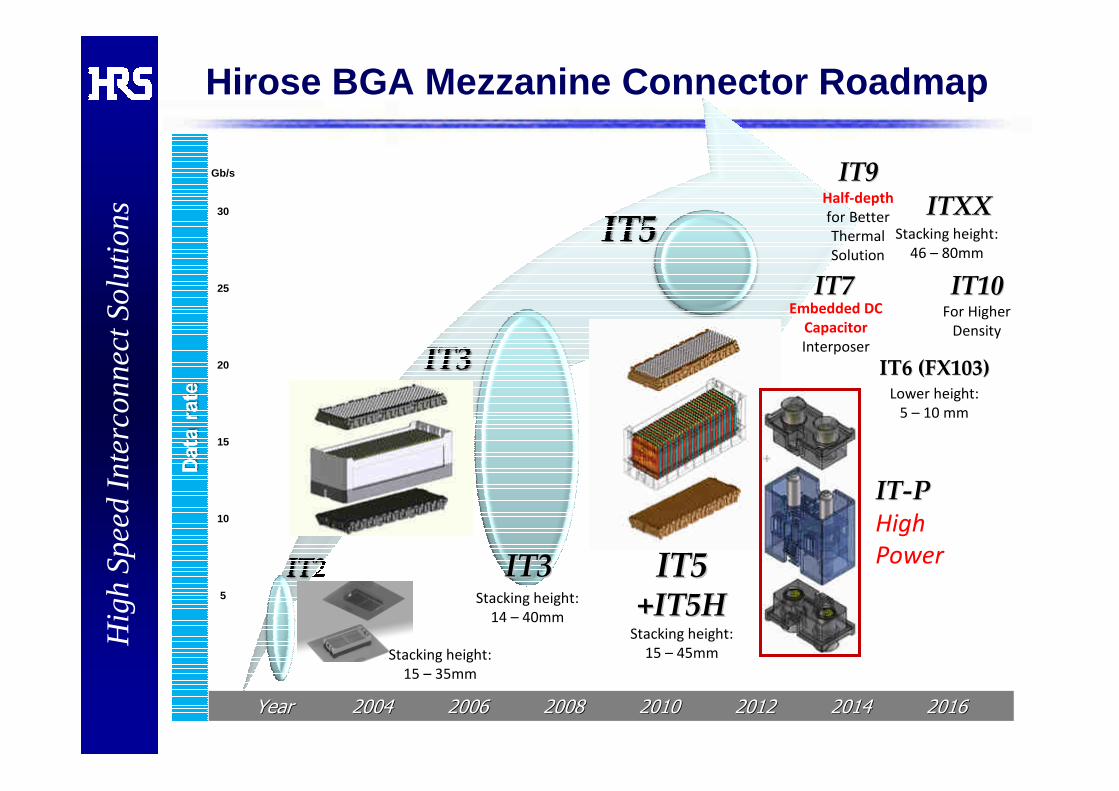
High -Speed Mezzanine Connector CoverageGb/s
35
30
25
20
15
10
5
Stack HeightStack Height 55 1010 1515 2020 3030 4040 4545
FX10
SMT SMT -- XG1XG1(0.5 mm pitch)(0.5 mm pitch)
BGA BGA -- IT3 / IT5 / IT7IT3 / IT5 / IT7(0.75 x 0.875 mm pitch)(0.75 x 0.875 mm pitch)
SMT SMT –– FX18FX18(0.8mm pitch)(0.8mm pitch)
SMT SMT -- FX10FX10(0.5 mm pitch)(0.5 mm pitch)
SMT SMT -- FX11FX11(0.5 mm pitch)(0.5 mm pitch)
BGA BGA –– IT9IT9
SMT SMT -- FX103 / FX113FX103 / FX113(0.5 mm pitch)(0.5 mm pitch)
Hig
h Sp
eed
Inte
rcon
nect
Sol
utio
nsH
igh
Spee
d In
terc
onne
ct S
olut
ions
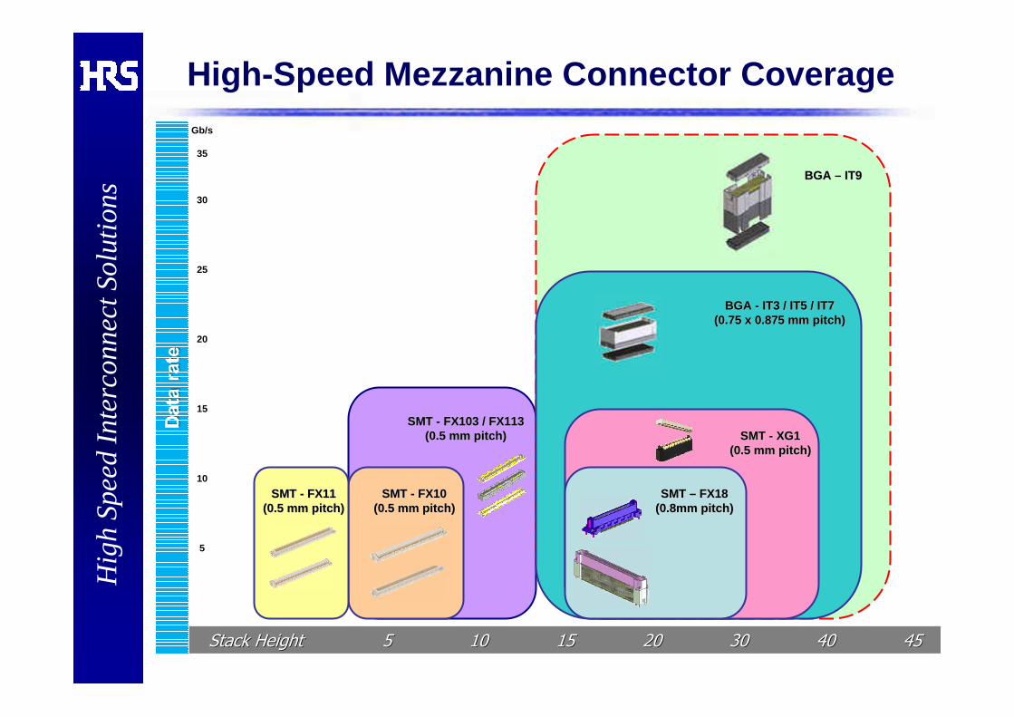
IT3 & IT5 Series Design Overview
Flexibility:Hirose’s IT3 &IT5 mezzanine connector
systems are as comfortable in today’s data
rates of PCIe and XAUI as it is in tomorrow’s
25+Gb/s systems.
With the ability to transmit differential,
single-ended, and power through one
package and being stackable from 14 – 45
mm, IT3 & IT5 can solve your interface
needs for both current and future
generations.
Features:•Unique 3-piece structure for excellent
reflow solderability
•Differential , single-ended, and power
•Low mating/extracting forces
•Wide misalignment tolerances
•Stacking heights from 14 to 45mm
•Both SnPb and Pb-free are available
•Staggered 1.5mm x 1.75mm BGA
A New Standard Mezzanine for Flexibility and Performance
Flexible 3-piece design* has many advantagesFlexible Flexible 33--piece design*piece design* has many advantageshas many advantages
Detachable (Mating) receptacle: IT3/5D-***S-BGA(**)
BGA
Interposer assembly: IT5-***P-**H(**)
Detachable SideMating / un-mating
Mounting receptacle: IT3/5M-***S-BGA(**)
Mounting SideInstalled and locked
Locking latch
Interposer
Signal Ground
Signal / Ground Configuration
*3-piece design is HRS Patented Technology

Hig
h Sp
eed
Inte
rcon
nect
Sol
utio
nsH
igh
Spee
d In
terc
onne
ct S
olut
ions
FY2012FY2012 –– IT3 Series VariationsIT3 Series Variations100 signals 200 signals 300 signals
10 x 10 20 x 10 30 x 10
Pb Mounting IT3M-100S-BGA(57) IT3M-200S-BGA(57) IT3M-300S-BGA(57)
Pb Mating IT3D-100S-BGA(57) IT3D-200S-BGA(57) IT3D-300S-BGA(57)
Pb-free Mounting IT3M-100S-BGA(37) IT3M-200S-BGA(37) IT3M-300S-BGA(37)
Pb-free Mating IT3D-100S-BGA(37) IT3D-200S-BGA(37) IT3D-300S-BGA(37)
14 mm IT3M-100P-14BGA IT3M-200P-14BGA IT3M-300P-14BGA
15 mm IT3M-100P-15BGA IT3M-200P-15BGA IT3M-300P-15BGA
16 mm IT3M-100P-15BGA +IT5HD IT3M-200P-15BGA +IT5HD IT3M-30 0P-15BGA +IT5HD
17 mm Currently no plan IT3-200P-17H(03) IT3-300P-17H(03)
18 mm Under planning IT3-200P-18H(03) IT3-300P-17H(03)+IT5HM
19 mm Currently no plan IT3-200P-18H(03) +IT5HM IT3-300P-17H(03)+IT5HM /HD
20 mm IT3-100P-20H(03) IT3-200P-20H(03) IT3-300P-20H(03)
21 mm IT3-100P-20H(03) +IT5HM IT3-200P-20H(03) +IT5HM IT3-300P-20H(03)+IT5HM
22 mm IT3-200P-20H(03)+IT5HM /HD IT3-200P-22H(03) IT3-300P-22H(03)
23 mm Currently no plan IT3-200P-22H(03) +IT5HM IT3-300P-22H(03)+IT5HM
24 mm Currently no plan IT3-200P-22H(03)+IT5HM /HD IT3-300P-22H(03)+IT5HM /HD
25 mm IT3-100P-25H(03) IT3-200P-25H(03) IT3-300P-25H(03)
26 mm IT3-100P-26H(03) IT3-200P-26H(03) IT3-300P-26H(03)
27 mm IT3-100P-26H(03) +IT5HM IT3-200P-26H(03) +IT5HM IT3-300P-26H(03)+IT5HM
28 mm IT3-100P-28H(03) IT3-200P-28H(03) IT3-300P-28H(03)
29 mm IT3-100P-28H(03) +IT5HM IT3-200P-28H(03) +IT5HM IT3-300P-28H(03)+IT5HM
30 mm IT3-200P-28H(03)+IT5HM /HD IT3-200P-30H(03) IT3-300P-30H(03)
31 mm Currently no plan IT3-200P-30H(03) +IT5HM IT3-300P-30H(03)+IT5HM
32 mm Currently no plan IT3-200P-32H(03) IT3-300P-32H(03)
33 mm Currently no plan IT3-200P-32H(03) +IT5HM IT3-300P-32H(03)+IT5HM
34 mm Currently no plan IT3-200P-32H(03)+IT5HM /HD IT3-300P-32H(03)+IT5HM /HD
35 mm IT3-100P-35H(03) IT3-200P-35H(03) IT3-300P-35H(03)
36 mm IT3-100P-35H(03) +IT5HM IT3-200P-35H(03) +IT5HM IT3-300P-35H(03)+IT5HM
37 mm IT3-100P-35H(03)+IT5HM /HD IT3-200P-35H(03)+IT5HM /HD IT3-300P-35H(03)+IT5HM /HD
38 mm IT3-100P-38H(03) IT3-200P-38H(03) IT3-300P-38H(03)
39 mm IT3-100P-38H(03) +IT5HM IT3-200P-38H(03) +IT5HM IT3-300P-38H(03)+IT5HM
40 mm IT3-100P-40H(03) IT3-200P-40H(03) IT3-300P-40H(03)
41 mm IT3-100P-40H(03) +IT5HM IT3-200P-40H(03) +IT5HM IT3-300P-40H(03)+IT5HM
42 mm IT3-100P-40H(03)+IT5HM /HD IT3-200P-40H(03)+IT5HM /HD IT3-300P-40H(03)+IT5HM /HD
Stacking Height
Soc
kets
Inte
rpos
ers (P
lugs
)
Note: Part numbers shown are Production Released product
IT3/5 family passes EIA364IT3/5 family passes EIA364--1000 L1 and IPC9702 L2 Qualifications1000 L1 and IPC9702 L2 Qualifications
Blue fonts = Available, Green = Newly available

Hig
h Sp
eed
Inte
rcon
nect
Sol
utio
nsH
igh
Spee
d In
terc
onne
ct S
olut
ions
FY2012FY2012 –– IT5 Series VariationsIT5 Series Variations100 signals 200 signals 300 signals
10 x 10 20 x 10 30 x 10
+1mm Mounting IT5HM-100S-BGA(37) IT5HM-200S-BGA(37) IT5HM-300S-BGA( 37)
+1mm Detachable IT5HD-100S-BGA(37) IT5HD-200S-BGA(37) IT5HD-300S-BGA( 37)
Pb-free Mounting IT5M-100S-BGA(37) IT5M-200S-BGA(37) IT5M-300S-BGA(37)
Pb-freeDetachable (Mating)
IT5D-100S-BGA(39) IT5D-200S-BGA(39) IT5D-300S-BGA(39)
14 mm IT5M1-100P-14H(03) Under planning Under planning
15 mm IT5-100P-14mm + IT5HM Under planning Under planning
16 mm IT5-100P-14mm + IT5HM /HD Under planning Under planning
17 mm Under planning Under planning Under planning
18 mm IT5x-100P-18H(03) IT5x-200P-18H(03) IT5x-300P-18H(03)
19 mm IT5-100P-18mm + IT5HM IT5-200P-18mm + IT5HM IT5-300P- 18mm + IT5HM
20 mm IT5-100P-18mm + IT5HM /HD IT5-200P-18mm + IT5HM /HD IT5 -300P-18mm + IT5HM /HD
22 mm IT5x-100P-22H(03) IT5x-200P-22H(03) IT5x-300P-22H(03)
23 mm IT5-100P-22mm + IT5HM IT5-200P-22mm + IT5HM IT5-300P- 22mm + IT5HM
24 mm IT5-100P-22mm + IT5HM /HD IT5-200P-22mm + IT5HM /HD IT5 -200P-22mm + IT5HM /HD
25 mm IT5x-100P-25H(03) IT5x-200P-25H(03) IT5x-300P-25H(03)
26 mm IT5-100P-25mm + IT5HM IT5-200P-25mm + IT5HM IT5-300P- 25mm + IT5HM
27 mm IT5-100P-26mm + IT5HM /HD IT5-200P-26mm + IT5HM /HD IT5 -300P-26mm + IT5HM /HD
28 mm IT5x-100P-28H(03) IT5x-200P-28H(03) IT5x-300P-28H(03)
29 mm IT5-100P-28mm + IT5HM IT5-200P-28mm + IT5HM IT5-300P- 28mm + IT5HM
30 mm IT5-100P-28mm + IT5HM /HD IT5-200P-28mm + IT5HM /HD IT5 -300P-28mm + IT5HM /HD
32 mm Under planning IT5x-200P-28H(03) IT5x-300P-28H(03)
33 mm Under planning IT5-200P-32mm + IT5HM IT5-300P-32mm + IT5HM
34 mm Under planning IT5-200P-32mm + IT5HM /HD IT5-200P-32mm + IT5HM /HD
35 mm IT5x-100P-35H(03) IT5x-200P-35H(03) IT5x-300P-35H(03)
36 mm IT5-100P-35mm + IT5HM IT5-200P-35mm + IT5HM IT5-300P- 35mm + IT5HM
37 mm IT5-100P-35mm + IT5HM /HD IT5-200P-35mm + IT5HM /HD IT5 -200P-35mm + IT5HM /HD
38 mm IT5x-100P-38H(03) IT5x-200P-38H(03) IT5x-300P-38H(03)
39 mm IT5-100P-38mm + IT5HM IT5-200P-38mm + IT5HM IT5-300P- 38mm + IT5HM
40 mm IT5-100P-38mm + IT5HM /HD IT5-200P-38mm + IT5HM /HD IT5 -300P-38mm + IT5HM /HD
Stacking Height
Soc
kets
Inte
rpos
ers
Blue fonts = Available, Green = Newly available
Note: Part numbers shown are Production Released productIT5 family passes EIA364IT5 family passes EIA364--1000 L1 and IPC9702 L2 Qualifications1000 L1 and IPC9702 L2 Qualifications

Hig
h Sp
eed
Inte
rcon
nect
Sol
utio
nsH
igh
Spee
d In
terc
onne
ct S
olut
ions Wide rangeWide range
Mounting tolerance
Error from datum position
±0.3mm Max.
±0.
2mm
Max
Err
or fr
om d
atum
pos
ition
Floating interposer – unique flexible design Floating interposer Floating interposer –– unique flexible design unique flexible design
Floating interposer
ensures stable
signal connection.
Floating
Fixed
Fixed
Floating
Mating and Floating tolerance:
+/-0.3mm in X direction
+/-0.2mm in Y direction
Floating
Pin stubbing Pin stubbing ––preventive preventive
housing designhousing design
Exposed contacts
Existing solution
IT3 & IT5
Series
FloatingFloatinginterposerinterposer
Mechanical Design Benefit – 1

Hig
h Sp
eed
Inte
rcon
nect
Sol
utio
nsH
igh
Spee
d In
terc
onne
ct S
olut
ions Configurable InterposerConfigurable Interposer
Floating interposer – unique flexible design Floating interposer Floating interposer –– unique flexible design unique flexible design
IT3
wafer
IT5
wafer
Power
wafer
IT7
wafer
Lower forceInsertion and Extraction
Signalposition
IT3 Supplier A
200 pos. 90 N 145 N
300 pos. 135 N 218 N
Floating wafers would allow optimal alignment
for mating.
Insertion force comparison
Mechanical Design Benefit – 2

Hig
h Sp
eed
Inte
rcon
nect
Sol
utio
nsH
igh
Spee
d In
terc
onne
ct S
olut
ions
Low Thermal Mass for Reflow ProcessLow Thermal Mass for Reflow Process
X-ray inspection from bottom side
Simple receptacle design gives Simple receptacle design gives clear vision for Xclear vision for X --ray inspection.ray inspection.
• With any stacking height combination, receptacle is always
same and their heights are only 6mm.• Small size of receptacle has wide
process window for reflow profile.
No need to reflow
Reflow only receptacleReflow only receptacle
Receptacle reflow on PCB
Interposer mating D/C mating
LEAD FREE applications benefitfrom our easy reflow process design.
XX--ray Inspection Friendlyray Inspection Friendly
2nd Reflow 2nd Reflow Soldering Soldering
CompatibleCompatible
(IT3 series for 30mm height application) Major CEM’s confirmed that there was no issue
to mount IT3 series receptacles on the
bottom side of PCB for 2nd reflow soldering.
Mechanical Design Benefit – 3

Hig
h Sp
eed
Inte
rcon
nect
Sol
utio
nsH
igh
Spee
d In
terc
onne
ct S
olut
ions
What is IT5 connector
� IT5 is foot-print compatible with IT3.� In fact, IT5 is IT3 receptacles + HELIX interposers using patent-
pending FEXT cancellation technology.
HELIXHELIX Interposer
IT5 series
Receptacle : IT3D-***S-BGA(**)
Receptacle : IT3M-***S-BGA(**)
Interposer
: IT5-***P-**H(**)

Hig
h Sp
eed
Inte
rcon
nect
Sol
utio
nsH
igh
Spee
d In
terc
onne
ct S
olut
ions
IT5 FEXT Cancellation
� The polarity swapping technique has improved differential FEXT by whopping 30 to 40 dB!
� Insertion loss is improved, too.

Hig
h Sp
eed
Inte
rcon
nect
Sol
utio
nsH
igh
Spee
d In
terc
onne
ct S
olut
ions
� IT7 introduces embedded DC blocking capacitors to the high-speed BGA mezzanine connector system
� Unique benefits of the IT7 connector system:� Saves board space used by DC blocking capacitors.� Reduces the number of via discontinuities along the signal
path to improve channel performance.
IT7 Design
� PCB wafers will be usedfor ease of assembly
�Standard 0402 chipcapacitors are mounted for
ease of handling
� Traces are routedon surface, reducing via discontinuities
� Capacitor pads are optimized for impedance matching

Hig
h Sp
eed
Inte
rcon
nect
Sol
utio
nsH
igh
Spee
d In
terc
onne
ct S
olut
ions
IT9 series 4 and 6rows BGA area arrayIT9 series 4 and 6rows BGA area array
Recommendation product variation: 4, 6rows X 36columns (144, 216 pins).100% density @25Gbps based on QPI next Gen.Multiple connectors are available.
Conceptual stage (Mass production in end of 2013)
10-15mm stacking height (2 piece structure)
16-43mm stacking height(3 piece structure)
CONFIDENTIAL
IT9M-***S-BGAMounting
side
IT9M-***P-**BGA/ Plug
IT9 wafer / PlugNo crossed pairs (Straight)
25Gbps (fully populated)Used for Single EndedCan be used for power
IT9D-***S-BGADetachable (Mating)
side
IT9D-***S-BGADetachable (Mating)
side
IT9-***P-**H/ Interposer
SSGSSGSSGSSG…
GSSGSSGSSGSS…
SSGSSGSSGSSG…
Mating tolerance: X=+/-0.2mmY=+/-0.2mm
Multiple connectors are available.
Unique plug wafer structure (PAT pending)
Note:-1) PCB pad tolerance from fiducial: +/-0.05-2) Mounting tolerance: +/-0.03-3) Geometrical tolerance of each contacts of connector from datum: +/-0.15
Square root of sum of squares: Needs +/-0.16

Hig
h Sp
eed
Inte
rcon
nect
Sol
utio
nsH
igh
Spee
d In
terc
onne
ct S
olut
ions
IT-P seriesB-to -B Power Pin Connector
Key Features• 3-piece structure
• Designed to be assembled alongside IT3 and IT5
• Consistent low profile receptacles for ease of reflow assembly
• Variable height interposers for design flexibility
• 60A current rating
Mating receptacle
Interposer
Mounting receptacle

Hig
h Sp
eed
Inte
rcon
nect
Sol
utio
nsH
igh
Spee
d In
terc
onne
ct S
olut
ions
ITIT--P Series Height VariationsP Series Height Variations
Note: Part numbers in Gray are under planning.
Part numbers in Blue have samples available.ITIT--P passes EIA364P passes EIA364 --1000 L1 qualifications1000 L1 qualifications
Part numberBtoB height range
for respective interposer
Part numberBtoB height range
for respective interposer
IT-PM-2S-DIR(Common Mounting
Part)IT-PM-2S-DIR
(Common Mounting Part)
IT-PD-2S-DIR(Common Mating
Part)IT-PD-2S-DIR
(Common Mating Part)
17.5 30.519 32
18.5 32.520 34
20.5 34.522 36
22.5 36.524 38
24.5 38.526 40
26.5 40.528 42
28.5 42.530 44
Rec
epta
cles
Rec
epta
cles
IT-P-2P-31H
IT-P-2P-33H
Inte
rpos
ers
IT-P-2P-25H
IT-P-2P-27H
IT-P-2P-29H
IT-P-2P-18H
IT-P-2P-19H
IT-P-2P-37H
IT-P-2P-39H
IT-P-2P-41H
Inte
rpos
ers
IT-P-2P-43H
IT-P-2P-21H
IT-P-2P-23H
IT-P-2P-35H
Each interposer can cover stack height ranges betwe en -0.5 mm and +1 mm relative to the part number height (**H)

Hig
h Sp
eed
Inte
rcon
nect
Sol
utio
nsH
igh
Spee
d In
terc
onne
ct S
olut
ions
XG1 Series Design OverviewXG1 Series Design Overview
Features:Features:- 10+ Gbps SMT mezzanine connector- Multiple blade combinations
(Differential 100 & 85 ohms, Single-ended, Power)
- Wide Self Alignment- Anti-Buckling Structure- Excellent Soldering Reliability- Effective Mating Length: 1.2 mm
Receptacle
3-Piece Structure
Cross Section
GND Contact
Specifications:Specifications:・・・・・・・・ 0.5 mm Pitch / Double0.5 mm Pitch / Double --Row SMTRow SMT・・・・・・・・ Pin CountPin Count :::::::: 52 to 260 pos.52 to 260 pos.・・・・・・・・ Stacking Height: 15 to 20 mm (2Stacking Height: 15 to 20 mm (2 --Piece)Piece)
25 to 38 mm (325 to 38 mm (3 --Piece)Piece)
0.5 mm
2-Piece Structure
Stacking height = 15 to 20 mmStacking height = 25 to 38 mm
:Signal Pin
:Ground Pin
Interposer
Plug
Ground Plate
Unique Enhanced Ground Plate DesignUnique Enhanced Ground Plate Design
Transmission BladeTransmission Blade
Receptacle

Hig
h Sp
eed
Inte
rcon
nect
Sol
utio
nsH
igh
Spee
d In
terc
onne
ct S
olut
ions
Customizable Blade ConfigurationCustomizable Blade Configuration
Multiple blade combinations are available.Multiple blade combinations are available.Multiple blade combinations are available.
For Power SupplyFor Power SupplyCurrent Capacity:
7 Amps / Blade(≒≒≒≒ 0.54 A / pin)
For DifferentialFor Differential
Impedance: 100 ohms
For DifferentialFor Differential(Supports PCIe and QPI)
Impedance: 85 ohms
For Single EndedFor Single Ended
Impedance: 50 ohms
Grounded Pins
Dedicated Ground
GND Plate
Grounded Pins
Dedicated GroundGrounded Pins
Dedicated Ground
3.3 V @ 3 A12 V @ 2 A
(Return)
3.3 V @ 3 A(Return)
12 V @ 2 A
Ex.
*Standard Blade
Diff Pair GND Plate
Diff Pair GND Plate

Hig
h Sp
eed
Inte
rcon
nect
Sol
utio
nsH
igh
Spee
d In
terc
onne
ct S
olut
ions
FX10 Series Design OverviewFX10 Series Design Overview
Features:- 0.5mm signal contact pitch / Dual-Row SMT(Suited to high-density applications)
- High-speed transmission capability (10+ Gb/s)
- Metal fittings for added soldering retention
- High contact reliability(Effective mating length of 1.1mm for signal contacts)
- Standard Electrical Interface for the OIF 100G Long-Haul DWDM Transmission Module (MSA-100GLH)
Header(FX10A-120P/12-SV)
Receptacle(FX10A-120S/12-SV)

Hig
h Sp
eed
Inte
rcon
nect
Sol
utio
nsH
igh
Spee
d In
terc
onne
ct S
olut
ions
FX113-***P-**H
Features:- Wide range of mating tolerance (X,Y direction: +/-0.15)
- 0.5mm signal contact pitch / Double-Row SMT(Suited to high-density applications)
- High-speed transmission capability (14+Gbps)(1 signal : 1 ground arrangement, depending on data rate)
- Metal fittings for added solder strength
- High contact reliability(Effective mating length: 0.8 - 1.0mm for signal contact)
- Electrical Interface for the OIF 100G Long-Haul DWDM Transmission Module (MSA-100GLH)
FX103FX103 and FX113and FX113 Series Design OverviewSeries Design Overview
FX103-***P-*H
Flexibility:Hirose’s FX103 and FX113 mezzanine connector system is as comfortable in today’s data rates of PCIe and XAUI as it will be in tomorrow’s 14+Gbps. With the ability to transmit differential, single ended and power through one package, and stackable from 5-25 mm, FX103 and FX113 can solve your interface needs for both current and future generations.
New Interposer in development
Released headers
Same header
Same header
* Interposer shape is subject to change

Hig
h Sp
eed
Inte
rcon
nect
Sol
utio
nsH
igh
Spee
d In
terc
onne
ct S
olut
ions
FX103/FX113 Height VariationsFX103/FX113 Height Variations
�
�
�
3.0
�
�
�
2.5
�����140
�����100
�����80
7.06.56.05.55.0
���������96
���������64
�������������96
�������������64
�
�
�
20
�
�
�
7
�
�
�
19
�
�
�
6
�
�
�
18
�
�
�
5
�
�
�
17
�
�
�
4
�
�
�
21
�
�
�
8
�
�
�
16
����168
����144
����120
25242322
�
�
�
15
�
�
�
14
�
�
�
13
�
�
�
12
�
�
�
11
�
�
�
10
�
�
�
9
168
144
120
FX103
FX113
FX103 and FX113 can cover between 2.5 and 25mm stacking height without a break
PosHeight
HeightPos
Height
Pos’n 2pc structure
3pc structure

Hig
h Sp
eed
Inte
rcon
nect
Sol
utio
nsH
igh
Spee
d In
terc
onne
ct S
olut
ions
33--piece Connector Design Benefitspiece Connector Design Benefits
Floating Interposer – Unique Reliable Contact Design
Floating
Floating
FX103 and FX113 have three piecefloating structures.
YX
X direction: +/-0.15mm Y direction: +/-0.15mm
Mating Y cross section
Side sliding latch on mounting side
Mounting side header
Interposer
Mating side header
Wiping Length
Interposer X cross section
0.8-1.0 mm
0.8-1.0 mm

Hig
h Sp
eed
Inte
rcon
nect
Sol
utio
nsH
igh
Spee
d In
terc
onne
ct S
olut
ions
Multiple mating example
Wide RangeMounting Tolerance
Error from datum position
±±±±0.15mm Max.
±± ±±0.
15m
mM
axE
rror
from
dat
um p
ositi
on
33--piece Connector Design Benefitspiece Connector Design Benefits
Main board
Sub card
Multiply mounting
Floating Interposer – Multiple Mating Capability

Hig
h Sp
eed
Inte
rcon
nect
Sol
utio
nsH
igh
Spee
d In
terc
onne
ct S
olut
ions
FX18 Series Overview

Hig
h Sp
eed
Inte
rcon
nect
Sol
utio
nsH
igh
Spee
d In
terc
onne
ct S
olut
ions
Thank you !Thank you !
http://http://www.hiroseusa.comwww.hiroseusa.com
Hirose Electric USA, Inc.Hirose Electric USA, Inc.
High Speed InterconnectsHigh Speed Interconnects
3255 Scott Blvd. Bldg.7 Ste.101,3255 Scott Blvd. Bldg.7 Ste.101,
Santa Clara, CA 95054 U.S.A.Santa Clara, CA 95054 U.S.A.