Embed Size (px)
Citation preview
1
Technical and Specifi cation Information GB162 50kW – 100kW
GB162 cascades up to 800kW
GB162 wall mounted gas-fi red condensing boiler series
NEW 50kWmodel

2
Worcester and you, making a difference
As part of the Bosch Group, Worcester
products are designed and manufactured to
provide its customers with the high levels of
quality and reliability which are synonymous
with the Bosch name throughout the world.
As part of Europe’s largest supplier of
heating products, Worcester, Bosch Group
has the UK-based resources and support
capability to offer you the value-added
solutions you deserve. Worcester employs
more than 2,000 people, including a
nationwide network of Service Engineers
and technically trained Field Sales Managers.
These are supported by an experienced
technical services team which is able
to provide comprehensive support and
advice from system layout through
to installation.
Worcester is dedicated to providing high
performance, energy effi cient heating
and hot water systems for a wide range
of installations, including large domestic
properties and commercial applications
such as offi ces, schools, sports centres
and hotels.
2
3
The reception and main entrance at our Worcester headquarters
“At Worcester, we remain keen to embrace
new market opportunities and with an
increasing number of you now looking to
develop your business by branching into the
light commercial sector, we are pleased to
announce the addition of the GB162 model
to our gas-fi red boiler range. In doing so,
we will continue to deliver on our core
values of reliability, quality, effi ciency.”
Carl Arntzen,
Managing Director,
Bosch Thermotechnology Ltd.
3
Contents Page
GB162 condensing boiler series 4 - 5
Features of the GB162 condensing boiler series 6 - 7
GB commercial plate heat exchangers 8 - 9
Flexible system solutions 10
Technical data 11
Inside story 12
Installing the GB162 series 13
Installation requirements 14 - 15
Single boiler installation 16
Modulating pump group 17 - 18
Wiring diagrams 19 - 20
Fluing options 21 - 28
Energy management controls 29 - 30
4000 series boiler management 31 - 32
Cascade – quick and simple to install 33
Cascade technical information 34 - 39
GB162 boiler series and accessories 40 - 43
Training 44 - 46
After-sales 47
4
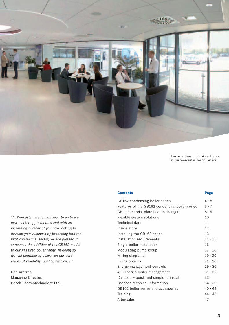
GB162 condensing boiler seriesThe GB162 is part of a market leading range of energy-
saving condensing wall mounted gas-fi red boilers.
The GB162 is an extremely versatile and compact wall
hung condensing boiler that can be installed on its own
or as part of a multi-boiler ‘cascade’ system. The boiler is
available with individual outputs of 50, 65, 80 and 100kW;
outputs of up to 800kW can be achieved when multiple
units are connected as part of a cascade installation.
Precise energy management
Each boiler in the GB162 series can automatically modulate
its output down to 30% or less in order to precisely match
the demand for heat. This considerably reduces fuel
consumption and improves overall seasonal effi ciency.
The GB162 is fully compatible with the Energy Management
System (EMS) modular controls platform. This optimises
performance by keeping the boiler in condensing mode
for as long as possible. EMS also provides comprehensive
heating system functionality and ensures minimal energy
usage at all times.
High effi ciency, low emissions
The GB162 provides net effi ciencies of up to 110% (NCV)
with ultra low class 5 levels of CO2 and NOx emissions.
Its compact dimensions make it especially suitable for
installations where space is restricted, but demand for
a modern high output heating solution is high.
Tax relief with the Carbon Trust
GB162 80kW and 100kW models are
registered on the Carbon Trust’s ECA
scheme (Enhanced Capital Allowance).
This will enable businesses to claim 100%
of the fi rst year capital allowance on
investments in energy saving technology.
For more details on how to register a claim
please visit www.etl.decc.gov.uk or follow the links on
www.worcester-bosch.co.uk/commercial.
55
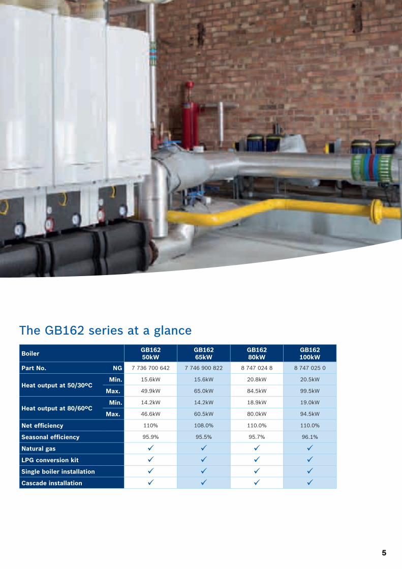
The GB162 series at a glance
Boiler GB1 6250kW
GB1 6265kW
GB16280kW
GB162100kW
Part No. NG 7 736 700 642 7 746 900 822 8 747 024 8 8 747 025 0
Heat output at 50/30ºCMin. 15.6kW 15.6kW 20.8kW 20.5kW
Max. 49.9kW 65.0kW 84.5kW 99.5kW
Heat output at 80/60ºCMin. 14.2kW 14.2kW 18.9kW 19.0kW
Max. 46.6kW 60.5kW 80.0kW 94.5kW
Net effi ciency 110% 108.0% 110.0% 110.0%
Seasonal effi ciency 95.9% 95.5% 95.7% 96.1%
Natural gas
LPG conversion kit
Single boiler installation
Cascade installation
6
Features of the GB162 condensing boiler series
Patented, award-winning ALU-Plus heat exchanger
The precision engineered heat exchanger in the GB162
is constructed from a cast aluminium silicate compound
which is lightweight, robust and allows for a rapid transfer
of heat. The heat exchanger also uses the very latest
ALU-Plus technology that has been developed by Bosch
Thermotechnology Ltd. to increase durability and optimise
heating effi ciency.
Fins on the outside of the aluminium tubes increase the
exterior surface area so that more hot fl ue gas comes into
contact with the heat exchanger.
A spiral channel on the inside of the tube increases the
internal surface area, bringing more water in contact with
the heating surface and ensuring an optimum heat transfer.
The wide channels on the heat exchanger ensure that the
fl ow resistance is minimised and this, combined with its
fully insulated case, makes the GB162 incredibly quiet
in operation.
Plasma-polymerised heat exchanger
The surfaces of the heat exchanger's tubes are treated
using a patented plasma-polymerisation process which
leaves the surfaces so smooth that the heat exchanger
effectively stays clean as no deposits can adhere to them.
Its extremely high effi ciency is maintained and there is no
need for mechanical cleaning; the heat exchanger can be
simply fl ushed through during servicing.
5 year guarantee heat exchanger
The ALU-Plus heat exchanger in the
GB162 is eligible for a 5 year guarantee*.
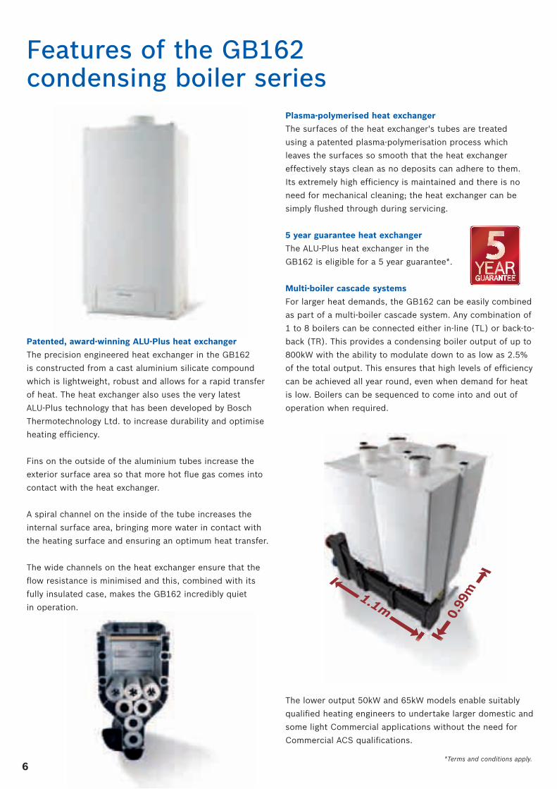
Multi-boiler cascade systems
For larger heat demands, the GB162 can be easily combined
as part of a multi-boiler cascade system. Any combination of
1 to 8 boilers can be connected either in-line (TL) or back-to-
back (TR). This provides a condensing boiler output of up to
800kW with the ability to modulate down to as low as 2.5%
of the total output. This ensures that high levels of effi ciency
can be achieved all year round, even when demand for heat
is low. Boilers can be sequenced to come into and out of
operation when required.
The lower output 50kW and 65kW models enable suitably
qualifi ed heating engineers to undertake larger domestic and
some light Commercial applications without the need for
Commercial ACS qualifi cations.
*Terms and conditions apply.
7
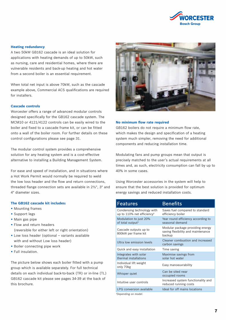
Heating redundancy
A two 50kW GB162 cascade is an ideal solution for
applications with heating demands of up to 50kW, such
as nursing, care and residential homes, where there are
vulnerable residents and back-up heating and hot water
from a second boiler is an essential requirement.
When total net input is above 70kW, such as the cascade
example above, Commercial ACS qualifi cations are required
for installers.
Cascade controls
Worcester offers a range of advanced modular controls
designed specifi cally for the GB162 cascade system. The
MCM10 or 4121/4122 controls can be easily wired to the
boiler and fi xed to a cascade frame kit, or can be fi tted
onto a wall of the boiler room. For further details on these
control confi gurations please see page 31.
The modular control system provides a comprehensive
solution for any heating system and is a cost-effective
alternative to installing a Building Management System.
For ease and speed of installation, and in situations where
a Hot Work Permit would normally be required to weld
the low loss header and the fl ow and return connections,
threaded fl ange connection sets are available in 2½", 3" and
4" diameter sizes.
The GB162 cascade kit includes:
• Mounting frames
• Support legs
• Main gas pipe
• Flow and return headers
(reversible for either left or right orientation)
• Low loss header (optional – variants available
with and without Low loss header)
• Boiler connecting pipe work
• Full insulation.
The picture below shows each boiler fi tted with a pump
group which is available separately. For full technical
details on each individual back-to-back (TR) or in-line (TL)
GB162 cascade kit please see pages 34-39 at the back of
this brochure.
No minimum fl ow rate required
GB162 boilers do not require a minimum fl ow rate,
which makes the design and specifi cation of a heating
system much simpler, removing the need for additional
components and reducing installation time.
Modulating fans and pump groups mean that output is
precisely matched to the user’s actual requirements at all
times and, as such, electricity consumption can fall by up to
40% in some cases.
Using Worcester accessories in the system will help to
ensure that the best solution is provided for optimum
energy savings and reduced installation costs.
7
Features Benefi tsCondensing technology with up to 110% net effi ciency†
Saves fuel compared to standard effi ciency boiler
Modulation to just 20% of total output†
Year round effi ciency according to seasonal demand
Cascade outputs up to 800kW per frame kit
Modular package providing energy saving fl exibility and maintenance backup
Ultra low emission levelsCleaner combustion and increased carbon savings
Quick and easy installation Time saving
Integrates with solar thermal installations
Maximise savings from solar hot water
Individual lift weight only 70kg
Easy manoeuvrability
Whisper quietCan be sited near occupied rooms
Intuitive user controlsIncreased system functionality and reduced running costs
LPG conversion available Ideal for off mains locations
†Depending on model.
8
Enhanced reliability and effi ciency
The GB plate heat exchanger ensures boiler water and
system water never meet. The heat exchanger protects
the boiler and therefore minimises potential downtime,
as well as improving long-term effi ciency.
Open-vented system
The GB plate heat exchanger allows GB162 boilers to
be installed on an open vented system. The plate heat
exchanger separates the primary (boiler) and secondary
(heating system), therefore protecting the boiler’s heat
exchanger from system water by effectively creating its own
sealed system. The plate heat exchanger can also be used
to provide boiler protection when installing within an old,
sealed secondary system.
Please note that system fl ushing and treating must still be
carried out as best practice. The plate heat exchanger is
sized on the basis of a boiler ∆T of 20°C and a system ∆T
of 11°C.
Sized to match all boiler outputs
Each GB plate heat exchanger has been sized to match all
possible combinations of GB162 boiler single and cascade
installations as indicated by the product name. This means
that the pump fl ow rates are suitable and allow heat to
effi ciently transfer in the plate heat exchanger, while
also ensuring that existing pumps can be used in cases
of retrofi t.
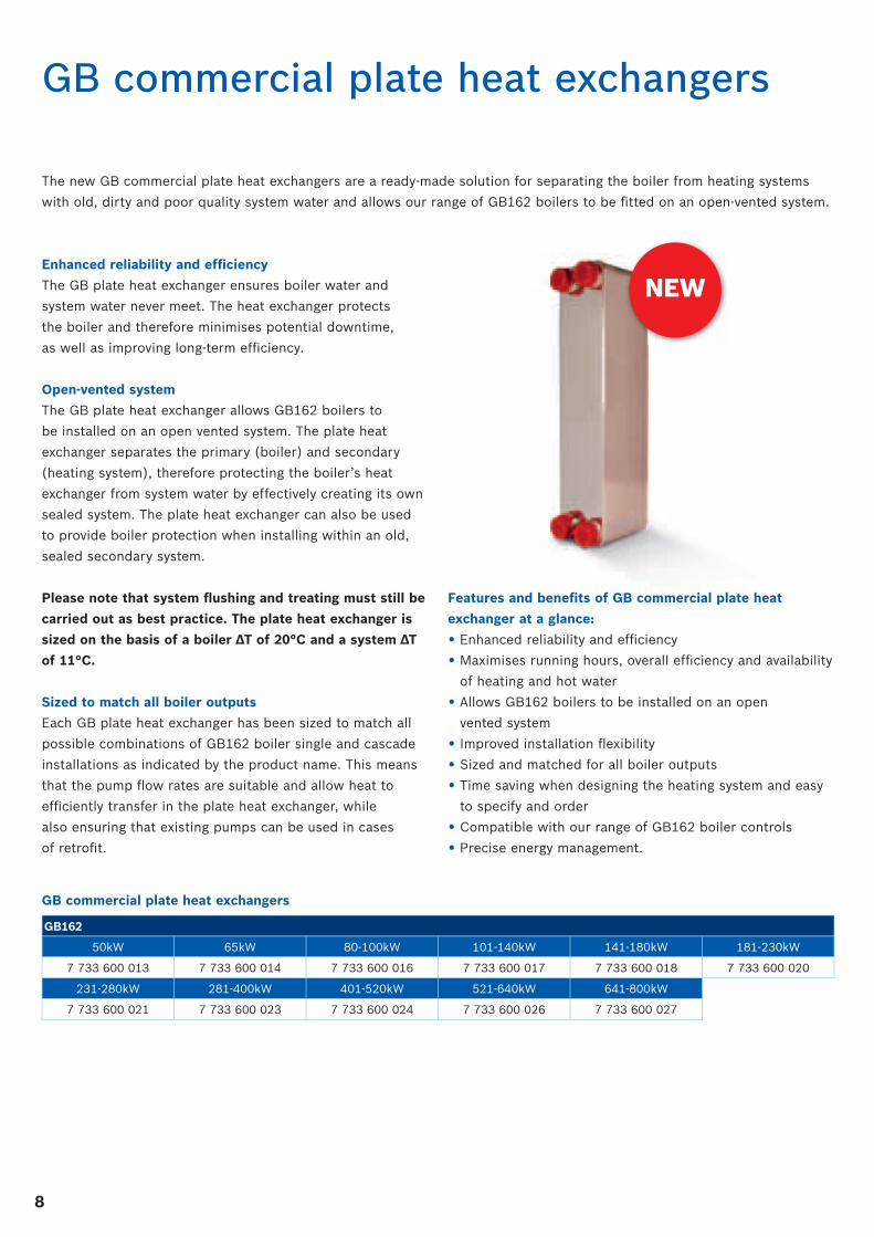
GB commercial plate heat exchangers
The new GB commercial plate heat exchangers are a ready-made solution for separating the boiler from heating systems
with old, dirty and poor quality system water and allows our range of GB162 boilers to be fi tted on an open-vented system.
Features and benefi ts of GB commercial plate heat
exchanger at a glance:
• Enhanced reliability and effi ciency
• Maximises running hours, overall effi ciency and availability
of heating and hot water
• Allows GB162 boilers to be installed on an open
vented system
• Improved installation fl exibility
• Sized and matched for all boiler outputs
• Time saving when designing the heating system and easy
to specify and order
• Compatible with our range of GB162 boiler controls
• Precise energy management.
NEW
GB162
50kW 65kW 80-100kW 101-140kW 141-180kW 181-230kW
7 733 600 013 7 733 600 014 7 733 600 016 7 733 600 017 7 733 600 018 7 733 600 020
231-280kW 281-400kW 401-520kW 521-640kW 641-800kW
7 733 600 021 7 733 600 023 7 733 600 024 7 733 600 026 7 733 600 027
GB commercial plate heat exchangers
9
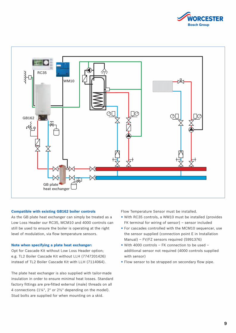
Compatible with existing GB162 boiler controls
As the GB plate heat exchanger can simply be treated as a
Low Loss Header our RC35, MCM10 and 4000 controls can
still be used to ensure the boiler is operating at the right
level of modulation, via fl ow temperature sensors.
Note when specifying a plate heat exchanger:
Opt for Cascade Kit without Low Loss Header option;
e.g. TL2 Boiler Cascade Kit without LLH (7747201426)
instead of TL2 Boiler Cascade Kit with LLH (7114064).
The plate heat exchanger is also supplied with tailor-made
insulation in order to ensure minimal heat losses. Standard
factory fi ttings are pre-fi tted external (male) threads on all
4 connections (1¼", 2" or 2½" depending on the model).
Stud bolts are supplied for when mounting on a skid.
Flow Temperature Sensor must be installed.
• With RC35 controls, a WM10 must be installed (provides
FK terminal for wiring of sensor) – sensor included
• For cascades controlled with the MCM10 sequencer, use
the sensor supplied (connection point E in Installation
Manual) – FV/FZ sensors required (5991376)
• With 4000 controls – FK connection to be used –
additional sensor not required (4000 controls supplied
with sensor)
• Flow sensor to be strapped on secondary fl ow pipe.
RC35
WM10
GB plate heat exchanger
GB162
GB162
RC35 WM10 MM10SM10
10
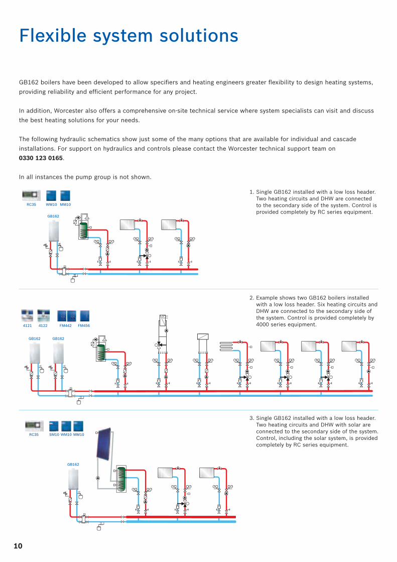
Flexible system solutions
GB162 boilers have been developed to allow specifi ers and heating engineers greater fl exibility to design heating systems,
providing reliability and effi cient performance for any project.
In addition, Worcester also offers a comprehensive on-site technical service where system specialists can visit and discuss
the best heating solutions for your needs.
The following hydraulic schematics show just some of the many options that are available for individual and cascade
installations. For support on hydraulics and controls please contact the Worcester technical support team on
0330 123 0165.
In all instances the pump group is not shown.
41224121
GB162 GB162
FM456 FM442
2. Example shows two GB162 boilers installed with a low loss header. Six heating circuits and DHW are connected to the secondary side of the system. Control is provided completely by 4000 series equipment.
RC35 WM10 MM10
GB162
1. Single GB162 installed with a low loss header. Two heating circuits and DHW are connected to the secondary side of the system. Control is provided completely by RC series equipment.
3. Single GB162 installed with a low loss header. Two heating circuits and DHW with solar are connected to the secondary side of the system. Control, including the solar system, is provided completely by RC series equipment.
11
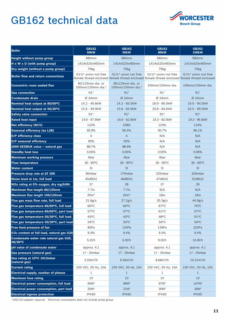
GB162 technical data
Boiler GB162 50kW
GB162 65kW
GB162 80kW
GB162 100kW
Height without pump group 980mm 980mm 980mm 980mm
H x W x D (with pump group) 1414x520x465mm 1414x520x465mm 1414x520x465mm 1414x520x465mm
Dry weight (without a pump group) 70kg 70kg 70kg 70kg
Boiler flow and return connectionsG1½" union nut free
female thread enclosedG1½" union nut free
female thread enclosedG1½" union nut free
female thread enclosedG1½" union nut free
female thread enclosed
Concentric room sealed flue80/125mm dia. or
100mm/150mm dia.*80/125mm dia. or
100mm/150mm dia.*100mm/150mm dia. 100mm/150mm dia.
Gas connection R1" R1" R1" R1"
Condensate drain Ø 24mm Ø 24mm Ø 24mm Ø 24mm
Nominal heat output at 80/60ºC 14.2 - 46.6kW 14.2 - 60.5kW 18.9 - 80.0kW 19.0 - 94.5kW
Nominal heat output at 50/30ºC 15.6 - 49.9kW 15.6 - 65.0kW 20.8 - 84.5kW 20.5 - 99.5kW
Safety valve connection R1" R1" R1" R1"
Rated heat input 14.6 - 47.5kW 14.6 - 62.0kW 19.3 - 82.0kW 19.3 - 96.5kW
Net efficiency (NCV) 110% 108% 110% 110%
Seasonal efficiency (as L2B) 95.9% 95.5% 95.7% 96.1%
ErP efficiency class A A N/A N/A
ErP seasonal efficiency 93% 92% N/A N/A
2009 SEDBUK value – natural gas 88.7% 88.9% N/A N/A
Standby heat loss 0.05% 0.05% 0.05% 0.06%
Maximum working pressure 4bar 4bar 4bar 4bar
Flow temperature 30 - 90ºC 30 - 90ºC 30 - 90ºC 30 - 90ºC
Water content 5l 5l 5l 5l
Pressure drop rate at ∆T 20K 90mbar 170mbar 225mbar 320mbar
Noise level at 1m, full load 45dB(A) 46dB(A) 47dB(A) 52dB(A)
NOx rating at 0% oxygen, dry mg/kWh 27 28 37 39
Maximum flue length 80/125mm 7.7m 7.7m N/A N/A
Maximum flue length 100/150mm 20m* 20m* 18m 18m
Flue gas mass flow rate, full load 21.6g/s 27.2g/s 35.3g/s 44.9g/s
Flue gas temperature 80/60ºC, full load 60ºC 64ºC 67ºC 76ºC
Flue gas temperature 80/60ºC, part load 57ºC 57ºC 61ºC 57ºC
Flue gas temperature 50/30ºC, full load 43ºC 43ºC 48ºC 51ºC
Flue gas temperature 50/30ºC, part load 33ºC 33ºC 34ºC 34ºC
Free feed pressure of fan 85Pa 120Pa 139Pa 220Pa
CO2 content at full load, natural gas G20 9.3% 9.4% 9.3% 9.4%
Condensate water rate natural gas G20, 40/30ºC
5.2l/h 6.9l/h 9.0l/h 10.8l/h
pH value of condensate water approx. 4.1 approx. 4.1 approx. 4.1 approx. 4.1
Gas pressure (natural gas) 17 - 25mbar 17 - 25mbar 17 - 25mbar 17 - 25mbar
Gas rating at 15ºC 1013mbar (natural gas)
5.03m3/h 6.56m3/h 8.68m3/h 10.21m3/h
Current rating 230 VAC, 50 Hz, 10A 230 VAC, 50 Hz, 10A 230 VAC, 50 Hz, 10A 230 VAC, 50 Hz, 10A
Electrical supply, number of phases 1 1 1 1
Maximum fuse rating 10 10 10 10
Electrical power consumption, full load 45W† 99W† 97W† 147W†
Electrical power consumption, part load 20W† 21W† 30W† 28W†
Electrical ingress protection IPX4D IPX4D IPX4D IPX4D
*100/150 adaptor required. †Electrical consumption does not include pump group.
12
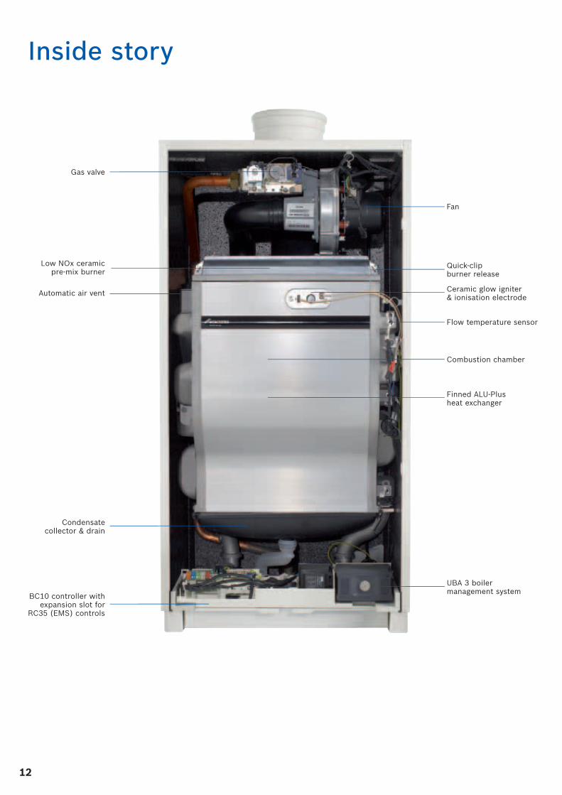
Inside story
Gas valve
Low NOx ceramic pre-mix burner
Automatic air vent
Fan
Quick-clip burner release
Ceramic glow igniter & ionisation electrode
Flow temperature sensor
Finned ALU-Plus heat exchanger
Combustion chamber
UBA 3 boiler management system
Condensate collector & drain
BC10 controller with expansion slot for
RC35 (EMS) controls
1313
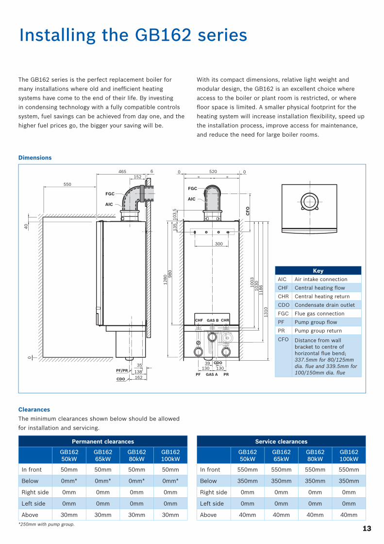
Installing the GB162 series
The GB162 series is the perfect replacement boiler for
many installations where old and ineffi cient heating
systems have come to the end of their life. By investing
in condensing technology with a fully compatible controls
system, fuel savings can be achieved from day one, and the
higher fuel prices go, the bigger your saving will be.
With its compact dimensions, relative light weight and
modular design, the GB162 is an excellent choice where
access to the boiler or plant room is restricted, or where
fl oor space is limited. A smaller physical footprint for the
heating system will increase installation fl exibility, speed up
the installation process, improve access for maintenance,
and reduce the need for large boiler rooms.
*250mm with pump group.
Clearances
The minimum clearances shown below should be allowed
for installation and servicing.
Permanent clearances
GB162 50kW
GB162 65kW
GB162 80kW
GB162 100kW
In front 50mm 50mm 50mm 50mm
Below 0mm* 0mm* 0mm* 0mm*
Right side 0mm 0mm 0mm 0mm
Left side 0mm 0mm 0mm 0mm
Above 30mm 30mm 30mm 30mm
Service clearances
GB162 50kW
GB162 65kW
GB162 80kW
GB162 100kW
In front 550mm 550mm 550mm 550mm
Below 350mm 350mm 350mm 350mm
Right side 0mm 0mm 0mm 0mm
Left side 0mm 0mm 0mm 0mm
Above 40mm 40mm 40mm 40mm
Dimensions
CDO
12
80 98
0
10
03
10
30
11
86
13
10
13
5
300
130 1303935
138162
CHF
PF PRGAS A
CDO
PF/PR
550
40
0
GAS B CHR
10
3.5
520465 6152
0 0
CFO
AIC
FGC
AIC
FGC
KeyAIC Air intake connection
CHF Central heating fl ow
CHR Central heating return
CDO Condensate drain outlet
FGC Flue gas connection
PF Pump group fl ow
PR Pump group return
CFO Distance from wall bracket to centre of horizontal fl ue bend; 337.5mm for 80/125mm dia. fl ue and 339.5mm for 100/150mm dia. fl ue
14
Installation requirements
These pages provide an overview of the main installation
and system requirements for the GB162. The full installation
instructions supplied with the boiler must be adhered to
before any work on the heating system takes place.
Where there is a secondary pump in the heating system, a
low loss header should be installed to separate the boilers
from the rest of the heating system. Fitting together with
the modulating pump group accessory ensures that fl ow
volumes are balanced, effi ciency is high and hydraulic
performance is optimised.
Regardless of whether a secondary pump is installed or not,
80kW and 100kW models should always be hydraulically
separated.
Hydraulic separation can also be achieved with a plate heat
exchanger – see pages 8-9.
Worcester's technical support team is available to offer
system design advice or if necessary make site visits. For
more details call 0330 123 0165.
Frost protection
The boiler has integrated frost protection which switches
the boiler on at a central heating fl ow temperature of 7°C
and switches it off at a central heating fl ow temperature
of 15°C.
Designated use
The boilers may only be used to heat water for sealed
heating systems of up to 4 bar. For greater system pressures
or open vented systems the boiler must be separated
from the heating system with a plate heat exchanger
(see page 9).
Quality of the heating system water
We strongly recommend thoroughly fl ushing the system
before fi lling it and using only untreated tap water when
fi lling the system. The use of dirty water will lead to
build-ups of sediment and corrosion, which can result
in the boiler malfunctioning and cause damage to the
heat exchanger.
DO NOT treat the water with products such as pH-adjusting
substances (chemical additives), antifreeze or water
softeners. Sentinel X100 or Fernox MB-1 can be used to
achieve the desired water quality. The concentration of
Sentinel or Fernox should be at least 1% of the volume of
the water in the system.
The pH of the heating system water MUST be between
7 and 8.5. If this is not the case, please contact Worcester's
technical support team before proceeding.
Artifi cially softened water should not be used with
the GB162.
Wiring diagram
A detailed wiring diagram showing how to wire the boiler
and controls can be found on pages 19-20. We recommend
using either dedicated controls to maximise effi ciency or
control the GB162 with an existing 0 to 10V BMS signal.
The 50kW and 65kW boilers incorporate an RTH converter
allowing existing 230V controls to be connected (for single
boiler installations only).
Quality of the pipe work
When using plastic pipe work in the heating system, e.g.
for underfl oor heating, it has to be oxygen-tight according
to relevant UK Standards. If the plastic pipes do not comply
with these standards, the system parts must be separated
using a plate heat exchanger.
Maintenance schedule
The activities to be included in an annual inspection and
maintenance contract can be found in the service section
of the installation manual. If an inspection reveals that
maintenance activities are necessary, these activities must
be carried out.
Connection of gas and water
The boilers do not contain a factory installed circulation
pump. The boiler should be installed together with a
GB162 accessory pump group to ensure that the pump is
appropriately sized for the boiler. The pump group also
allows for an easier and quicker installation.
1515
65kW
50kW
80kW
100kW
500
450
400
350
300
250
200
150
100
50
0
0 500 1000 1500 2000 2500 3000 3500 4000 4500 5000
[mb
ar]
[l/h]
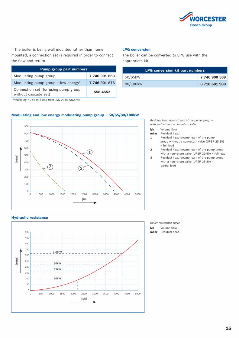
Boiler resistance curve
l/h Volume fl owmbar Residual head
Hydraulic resistance
[mb
ar]
900
800
700
600
500
400
300
200
100
0
[l/h]
0 500 1000 1500 2000 2500 3000 3500 4000 4500 5000
2
1
3
Residual head downstream of the pump group – with and without a non-return valve
l/h Volume fl owmbar Residual head1 Residual head downstream of the pump
group without a non-return valve (UPER 25-80) – full load
2 Residual head downstream of the pump group with a non-return valve (UPER 25-80) – full load
3 Residual head downstream of the pump group with a non-return valve (UPER 25-80) – partial load
Modulating and low energy modulating pump group – 50/65/80/100kW
LPG conversion
The boiler can be converted to LPG use with the
appropriate kit.
LPG conversion kit part numbers
50/65kW 7 746 900 509
80/100kW 8 718 601 980
If the boiler is being wall mounted rather than frame
mounted, a connection set is required in order to connect
the fl ow and return.
Pump group part numbers
Modulating pump group 7 746 901 863
Modulating pump group – low energy* 7 746 901 876
Connection set (for using pump group without cascade set)
558 4552
*Replacing 7 746 901 863 from July 2015 onwards.
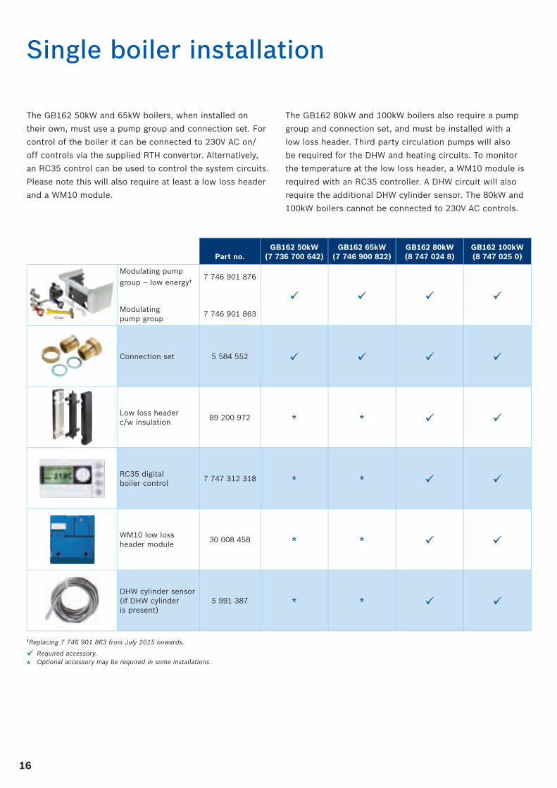
16
The GB162 50kW and 65kW boilers, when installed on
their own, must use a pump group and connection set. For
control of the boiler it can be connected to 230V AC on/
off controls via the supplied RTH convertor. Alternatively,
an RC35 control can be used to control the system circuits.
Please note this will also require at least a low loss header
and a WM10 module.
The GB162 80kW and 100kW boilers also require a pump
group and connection set, and must be installed with a
low loss header. Third party circulation pumps will also
be required for the DHW and heating circuits. To monitor
the temperature at the low loss header, a WM10 module is
required with an RC35 controller. A DHW circuit will also
require the additional DHW cylinder sensor. The 80kW and
100kW boilers cannot be connected to 230V AC controls.
Single boiler installation
Part no.GB162 50kW
(7 736 700 642)GB162 65kW
(7 746 900 822)GB162 80kW(8 747 024 8)
GB162 100kW(8 747 025 0)
Modulating pump
group – low energy†7 746 901 876
Modulating pump group
7 746 901 863
Connection set 5 584 552
Low loss header c/w insulation
89 200 972 * *
RC35 digital boiler control
7 747 312 318 * *
WM10 low loss header module
30 008 458 * *
DHW cylinder sensor(if DHW cylinder is present)
5 991 387 * *
†Replacing 7 746 901 863 from July 2015 onwards.
Required accessory.
* Optional accessory may be required in some installations.
1717
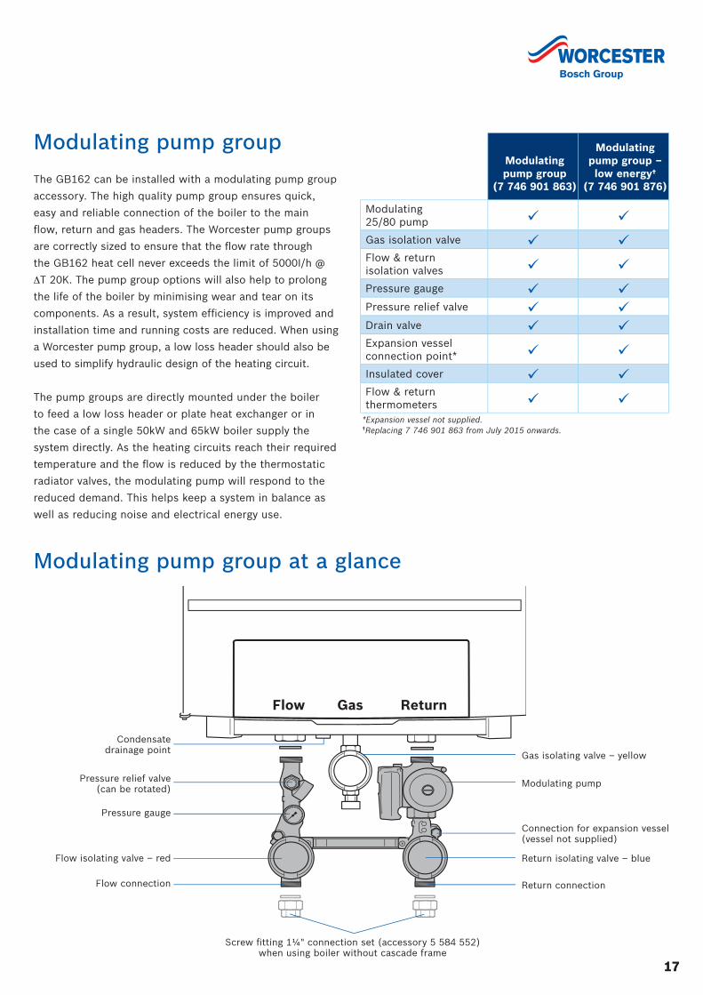
Modulating pump group
The GB162 can be installed with a modulating pump group
accessory. The high quality pump group ensures quick,
easy and reliable connection of the boiler to the main
fl ow, return and gas headers. The Worcester pump groups
are correctly sized to ensure that the fl ow rate through
the GB162 heat cell never exceeds the limit of 5000I/h @
ΔT 20K. The pump group options will also help to prolong
the life of the boiler by minimising wear and tear on its
components. As a result, system effi ciency is improved and
installation time and running costs are reduced. When using
a Worcester pump group, a low loss header should also be
used to simplify hydraulic design of the heating circuit.
The pump groups are directly mounted under the boiler
to feed a low loss header or plate heat exchanger or in
the case of a single 50kW and 65kW boiler supply the
system directly. As the heating circuits reach their required
temperature and the fl ow is reduced by the thermostatic
radiator valves, the modulating pump will respond to the
reduced demand. This helps keep a system in balance as
well as reducing noise and electrical energy use.
Modulating pump group
(7 746 901 863)
Modulatingpump group – low energy†
(7 746 901 876)
Modulating 25/80 pump
Gas isolation valve
Flow & return isolation valves
Pressure gauge
Pressure relief valve
Drain valve
Expansion vessel connection point*
Insulated cover
Flow & return thermometers
*Expansion vessel not supplied.†Replacing 7 746 901 863 from July 2015 onwards.
Flow ReturnGas
Pressure relief valve(can be rotated)
Pressure gauge
Condensate drainage point
Flow isolating valve – red
Flow connection
Modulating pump
Gas isolating valve – yellow
Connection for expansion vessel (vessel not supplied)
Return isolating valve – blue
Return connection
Screw fi tting 1¼" connection set (accessory 5 584 552) when using boiler without cascade frame
Modulating pump group at a glance
18
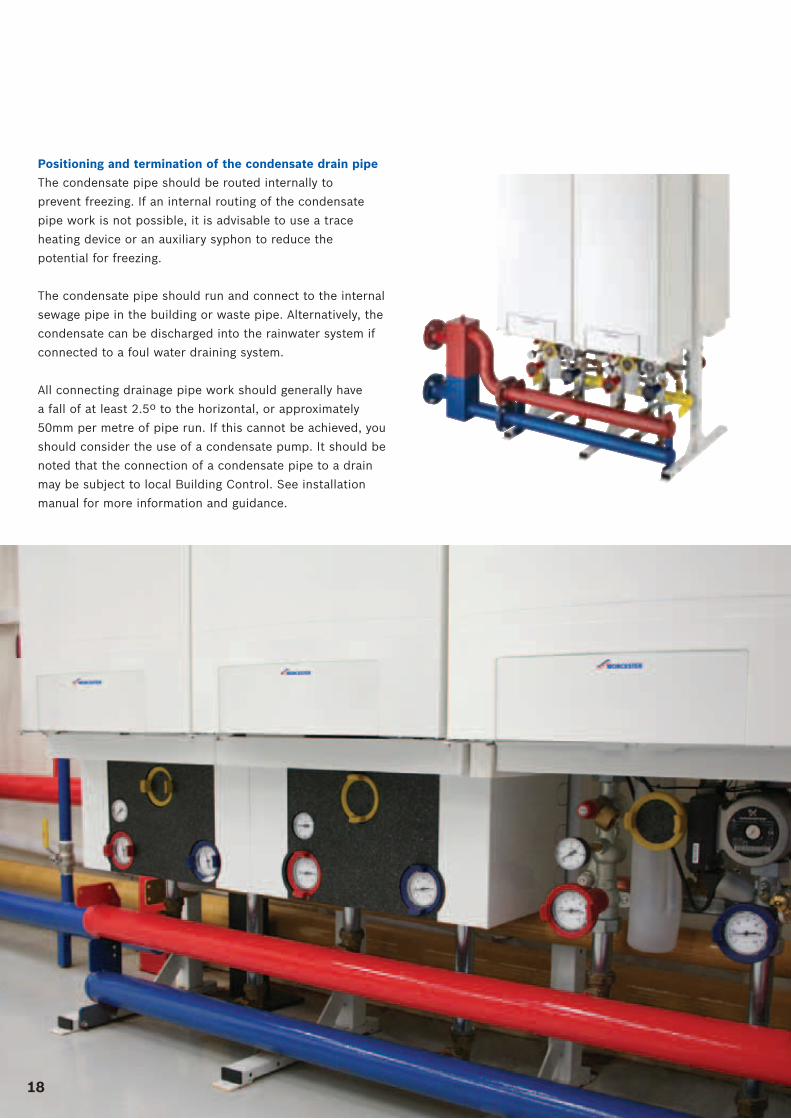
Positioning and termination of the condensate drain pipe
The condensate pipe should be routed internally to
prevent freezing. If an internal routing of the condensate
pipe work is not possible, it is advisable to use a trace
heating device or an auxiliary syphon to reduce the
potential for freezing.
The condensate pipe should run and connect to the internal
sewage pipe in the building or waste pipe. Alternatively, the
condensate can be discharged into the rainwater system if
connected to a foul water draining system.
All connecting drainage pipe work should generally have
a fall of at least 2.5º to the horizontal, or approximately
50mm per metre of pipe run. If this cannot be achieved, you
should consider the use of a condensate pump. It should be
noted that the connection of a condensate pipe to a drain
may be subject to local Building Control. See installation
manual for more information and guidance.
1919
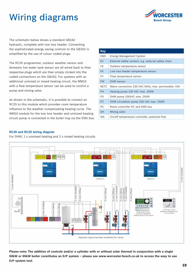
Wiring diagrams
The schematic below shows a standard GB162
hydraulic, complete with low loss header. Connecting
the sophisticated energy saving controls to the GB162 is
simplifi ed by the use of colour coded plugs.
The RC35 programmer, outdoor weather sensor and
domestic hot water tank sensor are all wired back to their
respective plugs which are then simply clicked into the
coded connections on the GB162. For systems with an
additional unmixed or mixed heating circuit, the MM10
with a fl ow temperature sensor can be used to control a
pump and mixing valve.
As shown in the schematic, it is possible to connect an
RC25 to this module which provides room temperature
infl uence to the weather compensating heating curve. The
WM10 module for the low loss header and unmixed heating
circuit pump is connected in the boiler tray via the EMS bus.
Please note: The addition of controls and/or a cylinder with or without solar thermal in conjunction with a single
50kW or 65kW boiler constitutes an ErP system – please see www.worcester-bosch.co.uk to access the easy to use
ErP system tool.
Key
EMS Energy Management System
EV External safety contact, e.g. external safety chain
FA Outdoor temperature sensor
FK Low loss header temperature sensor
FV Flow temperature sensor
FW DHW sensor
NETZ Mains connection 230 VAC 50Hz, max. permissible: 10A
PH Heating pump 230 VAC max. 250W
PS DHW pump 230VAC max. 250W
PZ DHW circulation pump 230 VAC max. 250W
RC Room controller RC and EMS bus
SH Mixing valve
WA On/off temperature controller, potential free
RC35 and RC25 wiring diagram
For DHW, 1 x unmixed heating and 2 x mixed heating circuits
2 c
ore
sh
ield
ed
2 c
ore
sh
ield
ed
2 c
ore
sh
ield
ed
3 c
ore
23
0va
c
3 c
ore
23
0va
c
2 c
ore
sh
ield
ed
Address 2 Address 3
RC25 set to sameaddress as heating circuit
it is to control RC35 used as room
controller, assigned to heating circuit it is to control
FA
North
3 c
ore
23
0va
c
4 c
ore
23
0va
c
3 c
ore
23
0va
c
3 c
ore
23
0va
c
2 c
ore
sh
ield
ed 4
co
re 2
30
vac
3 c
ore
23
0va
c 2
co
re s
hie
lded
Hydraulic layout has been simplified for clarity
FK
FW
FV FV
MM10WM10 MM10
1 2 EMS
N L E
NETZ
1 2 FA
1 2 FW
1 2 EV
1 2 RC
1 2 WA
24 25 E
PS
13 14 E
PZ
FV RC EMS1 2 1 2 1 2N LE N L E
NETZ NETZ
61 63 PH
43 44 41
SH FV RC EMS1 2 1 2 1 261 63
PH43 4441
SHN LE
NETZN LE
NETZ61 63 PH
1 2 FK
1 2 EMS
1 2 EMS
N L E
NETZ N L E
NETZ
20
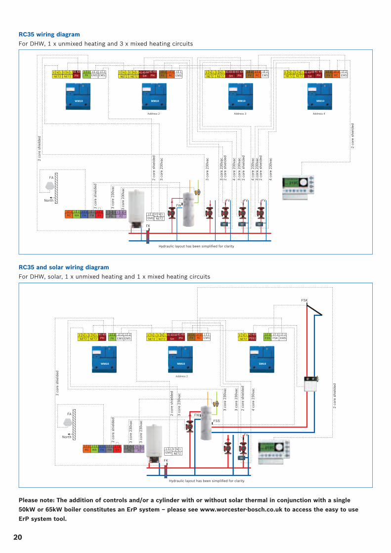
RC35 wiring diagram
For DHW, 1 x unmixed heating and 3 x mixed heating circuits
61 63
PH
1 2 FA
1 2 FV
1 2RC
1 2 EMS
61 63
PH 1 2 FK
1 2 EMS
1 2 EMS
1 2 FW
1 2 EV
61 63
PH 1 2 FV
1 2 RC
1 2 EMS
61 63
PH 1 2 FV
1 2 RC
1 2 EMS
43 44 41 SH
FA
North
2 c
ore
sh
ield
ed
1 2 RC
2 c
ore
sh
ield
ed
2 c
ore
sh
ield
ed
3 c
ore
23
0va
c
3 c
ore
23
0va
c
4 c
ore
23
0va
c
Hydraulic layout has been simplified for clarity
N L E
NETZ N L E
NETZ N L E
NETZ N L E
NETZ
1 2
EMS N L E
NETZ
1 2 WA
24 25 E
PS 13 14 E
PZ
3 c
ore
23
0va
c
2 c
ore
sh
ield
ed
Address 2
FK
FV
FW
3 co
re 2
30va
c
3 c
ore
23
0va
c
2 c
ore
sh
ield
ed
434441
SH N L E
NETZ N L E
NETZ
Address 3
FV
4 c
ore
23
0va
c
3 c
ore
23
0va
c 2
co
re s
hie
lded
434441
SH N L E
NETZ N L E
NETZ
Address 4
FV
4 c
ore
23
0va
c
2 c
ore
sh
ield
ed
3 c
ore
23
0va
c
WM10 MM10 MM10 MM10
RC35 and solar wiring diagram
For DHW, solar, 1 x unmixed heating and 1 x mixed heating circuits
61 63 PH
1 2 FA
1 2FV
1 2RC
1 2 EMS
61 63 PH
1 2
FK 1 2
EMS 1 2
EMS
1 2 FW
1 2 EV
1 2FSS
1 2FSK
1 2 EMS
61 63
PSS143 44 41
SH
2 c
ore
sh
ield
ed
1 2 RC
2 c
ore
sh
ield
ed
3 c
ore
23
0va
c
3 c
ore
23
0va
c
4 c
ore
23
0va
c
Hydraulic layout has been simplified for clarity
N L E
NETZ N L E
NETZ N L E
NETZ N L E
NETZ
1 2 EMS
N L E
NETZ
1 2 WA
24 25 E PS
13 14 E PZ
2 c
ore
sh
ield
ed
Address 2
FK
FV
FW
3 c
ore
23
0va
c
3 c
ore
23
0va
c
2 c
ore
sh
ield
ed
N LE
NETZ
FSS
FSK
2 c
ore
sh
ield
ed
3 c
ore
23
0va
c
WM10 MM10 SM10
FA
North
Please note: The addition of controls and/or a cylinder with or without solar thermal in conjunction with a single
50kW or 65kW boiler constitutes an ErP system – please see www.worcester-bosch.co.uk to access the easy to use
ErP system tool.
2121
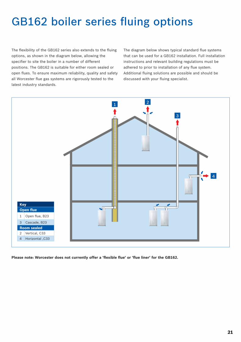
GB162 boiler series fl uing options
The fl exibility of the GB162 series also extends to the fl uing
options, as shown in the diagram below, allowing the
specifi er to site the boiler in a number of different
positions. The GB162 is suitable for either room sealed or
open fl ues. To ensure maximum reliability, quality and safety
all Worcester fl ue gas systems are rigorously tested to the
latest industry standards.
The diagram below shows typical standard fl ue systems
that can be used for a GB162 installation. Full installation
instructions and relevant building regulations must be
adhered to prior to installation of any fl ue system.
Additional fl uing solutions are possible and should be
discussed with your fl uing specialist.
KeyOpen fl ue
1 Open fl ue, B23
3 Cascade, B23
Room sealed2 Vertical, C33
4 Horizontal ,C33
1 2
3
4
Please note: Worcester does not currently offer a 'fl exible fl ue' or 'fl ue liner' for the GB162.

22
Horizontal and vertical fl ue terminal positioning
16
600
300
200
300
1,200
Boundary Line
1,500
1,500
2
1
12
11
10
9
5
187
6
13
15
4
3
17
14
300 300
300 300
300
300 300
500600
300
600
600
400
30025
8
300
500
600
6720643895-13.3Wo
300
252 25 16
Note
• Installations in car ports are not
recommended.
• The fl ue cannot be lower than 1,000mm
from the top of a light well due to the
build up of combustion products.
• Dimensions from a fl ue terminal to a
fanned air inlet to be determined by the
ventilation equipment manufacturer.
boilers less than 70kW
• Pluming will occur at the terminal so
terminal positions where this could
cause a nuisance should be avoided.
• The air supply and the fl ue gas
exhaust must meet the applicable
general regulations. Please consult
the instructions provided with the fl ue
terminal kits prior to installation.
• The boiler MUST be installed so that the
terminal is exposed to the external air.
• It is important that the position of the
terminal allows the free passage of air at
all times.
• Minimum acceptable spacing from the
terminal to obstructions and ventilation
openings are specifi ed above, for
domestic situations in accordance
with BS 5440.
Boilers greater than 70kW
• The fl ue must be installed in accordance
with the recommendations of IGE UP10.
Flue terminal positions for boilers up to 70kW in accordance with BS 5440
Key to illustration1. 300mm adjacent to a boundary line.
2. The dimension below eaves, balconies and car ports can be reduced to 25mm,
as long as the fl ue terminal is extended to clear any overhang. Any external fl ue
joints must be sealed with suitable silicon sealant.
3. 1,500mm between a vertical fl ue terminal and a window or dormer window.
4. 1,200mm between terminals facing each other.
5. Vertical fl ue clearance, 300mm adjacent to a boundary line, unless it will cause a
nuisance. BS 5440:Part 1 recommends that care is taken when siting terminal in
relation to boundary lines.
6. 600mm distance to a boundary line, unless it will cause a nuisance.
BS 5440:Part 1 recommends that care is taken when siting terminal in relation
to boundary lines.
7. 600mm minimum clearance from a skylight to a vertical fl ue.
8. Vertical fl ue clearance, 500mm to non-combustible building material,
and 1,500mm clearance to combustible building material.
9. 300mm above, below and either side of an opening door, air vent or
opening window.
10. 600mm diagonally to an opening door, air vent or opening window.
11. 300mm to an internal or external corner.
12. 2,000mm below a Velux window, 600mm above or to either side of the
Velux window.
13. 400mm from a pitched roof or in regions with heavy snow fall 500mm.
14. 500mm clearance to any vertical structure on a roof, 600mm to room sealed
fl ue or 1,500 to an open fl ue.
15. 200mm below eaves and 75mm below gutters, pipe and drains.
16. The dimension below eaves, balconies and car ports can be reduced to 25mm,
as long as the fl ue terminal is extended to clear any overhang. Any external fl ue
joints must be sealed with suitable silicon sealant.
17. Flue clearance must be at least 300mm from the ground. Terminal guards must
be fi tted if the fl ue is less than 2 metres from the ground or if a person could
come into contact with the fl ue terminal.
18. 600mm distance to a surface facing a terminal, unless it will cause a nuisance.
BS 5440: Part 1 recommends that care is taken when siting terminals in relation
to surfaces facing a terminal.
All measurements in millimetres
2323
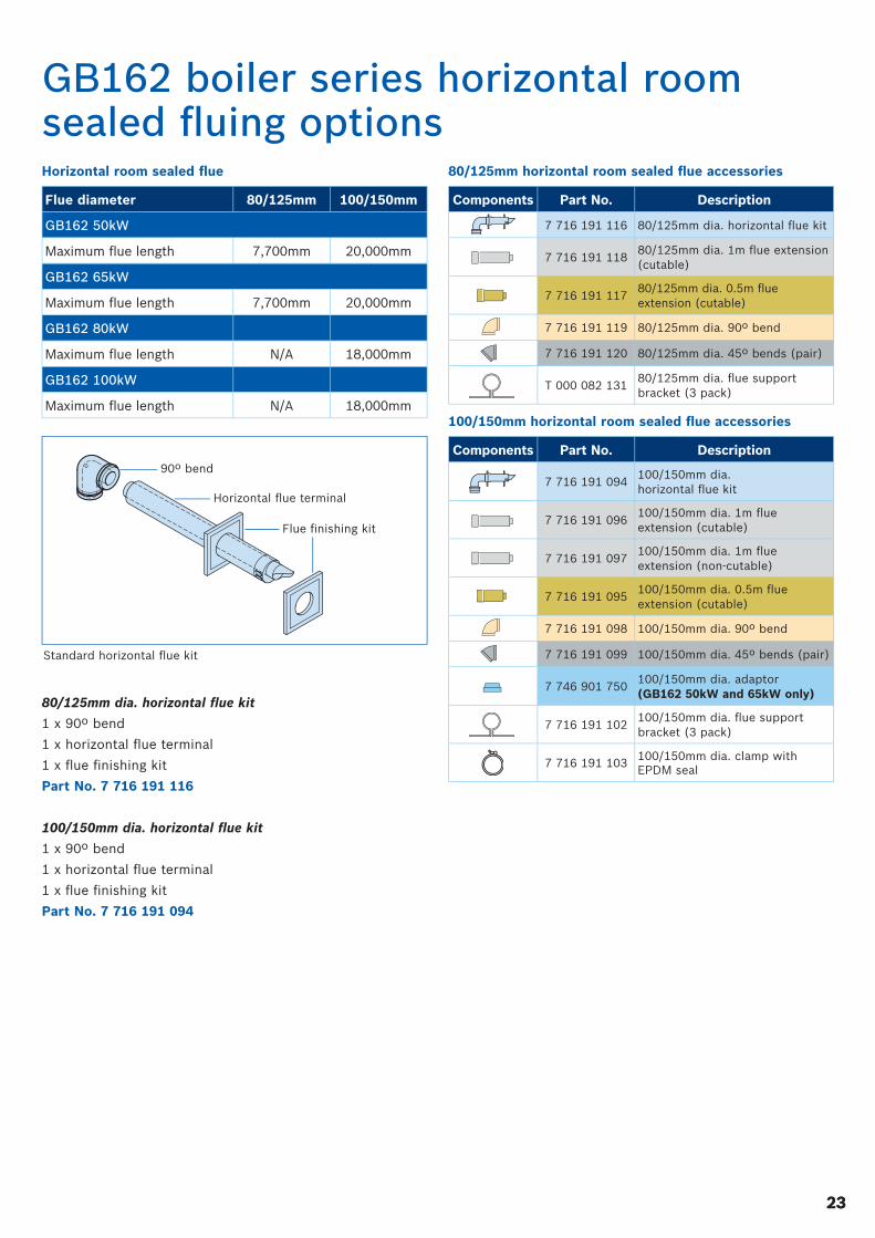
GB162 boiler series horizontal room sealed fl uing options
Flue diameter 80/125mm 100/150mm
GB162 50kW
Maximum fl ue length 7,700mm 20,000mm
GB162 65kW
Maximum fl ue length 7,700mm 20,000mm
GB162 80kW
Maximum fl ue length N/A 18,000mm
GB162 100kW
Maximum fl ue length N/A 18,000mm
Horizontal room sealed fl ue
80/125mm dia. horizontal fl ue kit
1 x 90º bend
1 x horizontal fl ue terminal
1 x fl ue fi nishing kit
Part No. 7 716 191 116
100/150mm dia. horizontal fl ue kit
1 x 90º bend
1 x horizontal fl ue terminal
1 x fl ue fi nishing kit
Part No. 7 716 191 094
Standard horizontal fl ue kit
90º bend
Horizontal fl ue terminal
Flue fi nishing kit
80/125mm horizontal room sealed fl ue accessories
100/150mm horizontal room sealed fl ue accessories
Components Part No. Description
7 716 191 116 80/125mm dia. horizontal fl ue kit
7 716 191 11880/125mm dia. 1m fl ue extension (cutable)
7 716 191 11780/125mm dia. 0.5m fl ue extension (cutable)
7 716 191 119 80/125mm dia. 90º bend
7 716 191 120 80/125mm dia. 45º bends (pair)
T 000 082 13180/125mm dia. fl ue support bracket (3 pack)
Components Part No. Description
7 716 191 094100/150mm dia. horizontal fl ue kit
7 716 191 096100/150mm dia. 1m fl ue extension (cutable)
7 716 191 097100/150mm dia. 1m fl ue extension (non-cutable)
7 716 191 095100/150mm dia. 0.5m fl ue extension (cutable)
7 716 191 098 100/150mm dia. 90º bend
7 716 191 099 100/150mm dia. 45º bends (pair)
7 746 901 750100/150mm dia. adaptor (GB162 50kW and 65kW only)
7 716 191 102100/150mm dia. fl ue support bracket (3 pack)
7 716 191 103100/150mm dia. clamp with EPDM seal
24
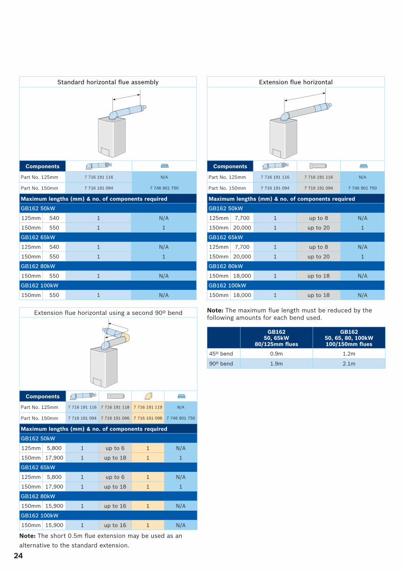
Note: The short 0.5m fl ue extension may be used as an
alternative to the standard extension.
Note: The maximum fl ue length must be reduced by the following amounts for each bend used.
GB162 50, 65kW
80/125mm fl ues
GB162 50, 65, 80, 100kW100/150mm fl ues
45º bend 0.9m 1.2m
90º bend 1.9m 2.1m
Extension fl ue horizontal
Components
Part No. 125mm 7 716 191 116 7 716 191 116 N/A
Part No. 150mm 7 716 191 094 7 716 191 094 7 746 901 750
Maximum lengths (mm) & no. of components required
GB162 50kW
125mm 7,700 1 up to 8 N/A
150mm 20,000 1 up to 20 1
GB162 65kW
125mm 7,700 1 up to 8 N/A
150mm 20,000 1 up to 20 1
GB162 80kW
150mm 18,000 1 up to 18 N/A
GB162 100kW
150mm 18,000 1 up to 18 N/A
Standard horizontal fl ue assembly
Components
Part No. 125mm 7 716 191 116 N/A
Part No. 150mm 7 716 191 094 7 746 901 750
Maximum lengths (mm) & no. of components required
GB162 50kW
125mm 540 1 N/A
150mm 550 1 1
GB162 65kW
125mm 540 1 N/A
150mm 550 1 1
GB162 80kW
150mm 550 1 N/A
GB162 100kW
150mm 550 1 N/A
Maximum lengths (mm) & no. of components required
GB162 50kW
125mm 5,800 1 up to 6 1 N/A
150mm 17,900 1 up to 18 1 1
GB162 65kW
125mm 5,800 1 up to 6 1 N/A
150mm 17,900 1 up to 18 1 1
GB162 80kW
150mm 15,900 1 up to 16 1 N/A
GB162 100kW
150mm 15,900 1 up to 16 1 N/A
Extension fl ue horizontal using a second 90º bend
Components
Part No. 125mm 7 716 191 116 7 716 191 118 7 716 191 119 N/A
Part No. 150mm 7 716 191 094 7 716 191 096 7 716 191 098 7 746 901 750
2525
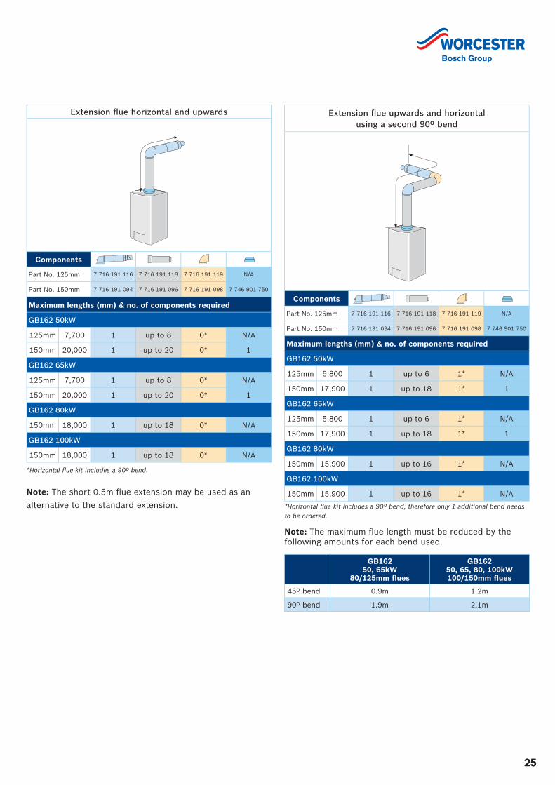
Extension fl ue upwards and horizontal using a second 90º bend
Components
Part No. 125mm 7 716 191 116 7 716 191 118 7 716 191 119 N/A
Part No. 150mm 7 716 191 094 7 716 191 096 7 716 191 098 7 746 901 750
Extension fl ue horizontal and upwards
Components
Part No. 125mm 7 716 191 116 7 716 191 118 7 716 191 119 N/A
Part No. 150mm 7 716 191 094 7 716 191 096 7 716 191 098 7 746 901 750
Maximum lengths (mm) & no. of components required
GB162 50kW
125mm 5,800 1 up to 6 1* N/A
150mm 17,900 1 up to 18 1* 1
GB162 65kW
125mm 5,800 1 up to 6 1* N/A
150mm 17,900 1 up to 18 1* 1
GB162 80kW
150mm 15,900 1 up to 16 1* N/A
GB162 100kW
150mm 15,900 1 up to 16 1* N/A
*Horizontal fl ue kit includes a 90º bend, therefore only 1 additional bend needs to be ordered.
Maximum lengths (mm) & no. of components required
GB162 50kW
125mm 7,700 1 up to 8 0* N/A
150mm 20,000 1 up to 20 0* 1
GB162 65kW
125mm 7,700 1 up to 8 0* N/A
150mm 20,000 1 up to 20 0* 1
GB162 80kW
150mm 18,000 1 up to 18 0* N/A
GB162 100kW
150mm 18,000 1 up to 18 0* N/A
*Horizontal fl ue kit includes a 90º bend.
Note: The short 0.5m fl ue extension may be used as an
alternative to the standard extension.
Note: The maximum fl ue length must be reduced by the following amounts for each bend used.
GB162 50, 65kW
80/125mm fl ues
GB162 50, 65, 80, 100kW100/150mm fl ues
45º bend 0.9m 1.2m
90º bend 1.9m 2.1m
26
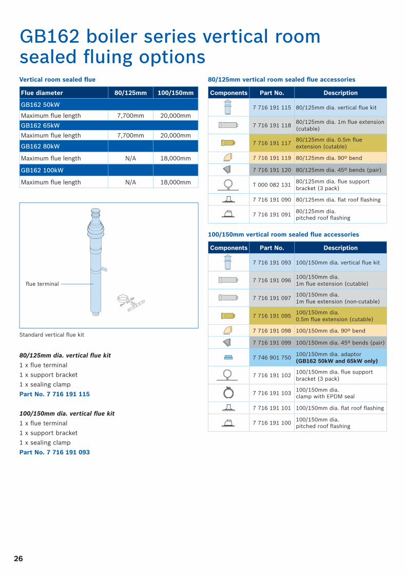
GB162 boiler series vertical room sealed fl uing options
Flue diameter 80/125mm 100/150mm
GB162 50kW
Maximum fl ue length 7,700mm 20,000mm
GB162 65kW
Maximum fl ue length 7,700mm 20,000mm
GB162 80kW
Maximum fl ue length N/A 18,000mm
GB162 100kW
Maximum fl ue length N/A 18,000mm
Vertical room sealed fl ue
support bracket
80/125mm dia. vertical fl ue kit
1 x fl ue terminal
1 x support bracket
1 x sealing clamp
Part No. 7 716 191 115
100/150mm dia. vertical fl ue kit
1 x fl ue terminal
1 x support bracket
1 x sealing clamp
Part No. 7 716 191 093
Standard vertical fl ue kit
fl ue terminal
Components Part No. Description
7 716 191 115 80/125mm dia. vertical fl ue kit
7 716 191 11880/125mm dia. 1m fl ue extension (cutable)
7 716 191 11780/125mm dia. 0.5m fl ue extension (cutable)
7 716 191 119 80/125mm dia. 90º bend
7 716 191 120 80/125mm dia. 45º bends (pair)
T 000 082 13180/125mm dia. fl ue support bracket (3 pack)
7 716 191 090 80/125mm dia. fl at roof fl ashing
7 716 191 09180/125mm dia. pitched roof fl ashing
Components Part No. Description
7 716 191 093 100/150mm dia. vertical fl ue kit
7 716 191 096100/150mm dia. 1m fl ue extension (cutable)
7 716 191 097100/150mm dia. 1m fl ue extension (non-cutable)
7 716 191 095100/150mm dia. 0.5m fl ue extension (cutable)
7 716 191 098 100/150mm dia. 90º bend
7 716 191 099 100/150mm dia. 45º bends (pair)
7 746 901 750100/150mm dia. adaptor (GB162 50kW and 65kW only)
7 716 191 102100/150mm dia. fl ue support bracket (3 pack)
7 716 191 103100/150mm dia. clamp with EPDM seal
7 716 191 101 100/150mm dia. fl at roof fl ashing
7 716 191 100100/150mm dia. pitched roof fl ashing
80/125mm vertical room sealed fl ue accessories
100/150mm vertical room sealed fl ue accessories
2727
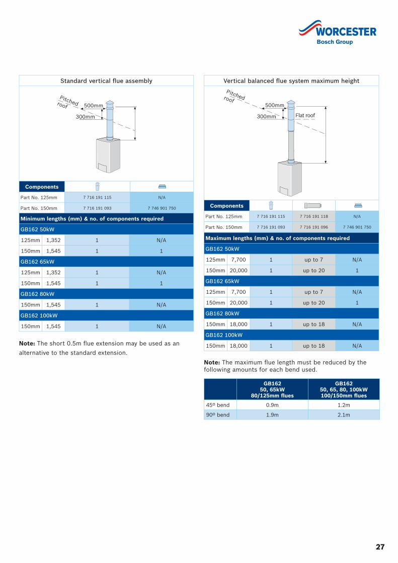
Standard vertical fl ue assembly
Components
Part No. 125mm 7 716 191 115 N/A
Part No. 150mm 7 716 191 093 7 746 901 750
Minimum lengths (mm) & no. of components required
GB162 50kW
125mm 1,352 1 N/A
150mm 1,545 1 1
GB162 65kW
125mm 1,352 1 N/A
150mm 1,545 1 1
GB162 80kW
150mm 1,545 1 N/A
GB162 100kW
150mm 1,545 1 N/A
300mm
500mm
Pitchedroof
Vertical balanced fl ue system maximum height
Components
Part No. 125mm 7 716 191 115 7 716 191 118 N/A
Part No. 150mm 7 716 191 093 7 716 191 096 7 746 901 750
Maximum lengths (mm) & no. of components required
GB162 50kW
125mm 7,700 1 up to 7 N/A
150mm 20,000 1 up to 20 1
GB162 65kW
125mm 7,700 1 up to 7 N/A
150mm 20,000 1 up to 20 1
GB162 80kW
150mm 18,000 1 up to 18 N/A
GB162 100kW
150mm 18,000 1 up to 18 N/A
300mm
500mm
Pitchedroof
Flat roof
Note: The short 0.5m fl ue extension may be used as an
alternative to the standard extension.
Note: The maximum fl ue length must be reduced by the following amounts for each bend used.
GB162 50, 65kW
80/125mm fl ues
GB162 50, 65, 80, 100kW100/150mm fl ues
45º bend 0.9m 1.2m
90º bend 1.9m 2.1m
28
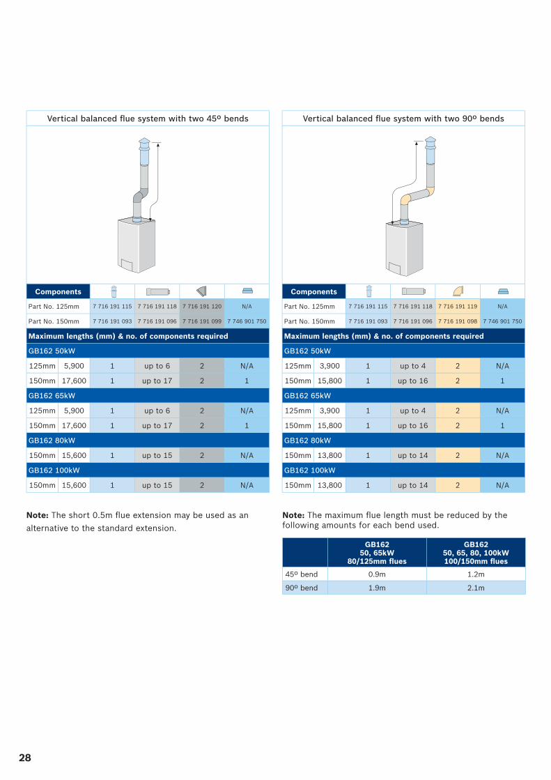
Vertical balanced fl ue system with two 45º bends
Components
Part No. 125mm 7 716 191 115 7 716 191 118 7 716 191 120 N/A
Part No. 150mm 7 716 191 093 7 716 191 096 7 716 191 099 7 746 901 750
Maximum lengths (mm) & no. of components required
GB162 50kW
125mm 5,900 1 up to 6 2 N/A
150mm 17,600 1 up to 17 2 1
GB162 65kW
125mm 5,900 1 up to 6 2 N/A
150mm 17,600 1 up to 17 2 1
GB162 80kW
150mm 15,600 1 up to 15 2 N/A
GB162 100kW
150mm 15,600 1 up to 15 2 N/A
Vertical balanced fl ue system with two 90º bends
Components
Part No. 125mm 7 716 191 115 7 716 191 118 7 716 191 119 N/A
Part No. 150mm 7 716 191 093 7 716 191 096 7 716 191 098 7 746 901 750
Maximum lengths (mm) & no. of components required
GB162 50kW
125mm 3,900 1 up to 4 2 N/A
150mm 15,800 1 up to 16 2 1
GB162 65kW
125mm 3,900 1 up to 4 2 N/A
150mm 15,800 1 up to 16 2 1
GB162 80kW
150mm 13,800 1 up to 14 2 N/A
GB162 100kW
150mm 13,800 1 up to 14 2 N/A
Note: The short 0.5m fl ue extension may be used as an
alternative to the standard extension.
Note: The maximum fl ue length must be reduced by the following amounts for each bend used.
GB162 50, 65kW
80/125mm fl ues
GB162 50, 65, 80, 100kW100/150mm fl ues
45º bend 0.9m 1.2m
90º bend 1.9m 2.1m
2929
Energy management controls
It is vital when fi tting any energy effi cient heating equipment that controls are not overlooked. The controls are designed
to maximise system effi ciency and allow the heating engineer quick and easy access to all functions of the boiler and
heating system. For the end user, selection of the most appropriate controls for the installation will result in greater
functionality of the system and more effi cient operation.
EMS (Energy Management System)
EMS is a state-of-the-art intelligent control system that uses a standard operating structure to ensure smooth and continuous
communication between the automatic fi ring of the boiler and the heating system controls. This improves overall effi ciency
and gives the heating engineer a large degree of fl exibility and control over the heating system, allowing individual circuits
and zones to be effectively managed. EMS is equipped as standard in the GB162 and is fully compatible with the high
performance range of the 4121/4122 modular controls as well as the RC35 digital programmer.
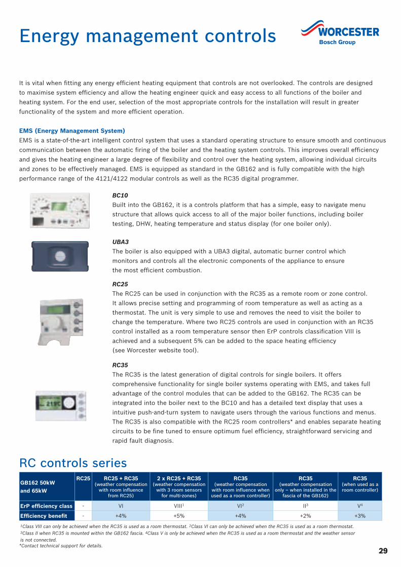
BC10
Built into the GB162, it is a controls platform that has a simple, easy to navigate menu
structure that allows quick access to all of the major boiler functions, including boiler
testing, DHW, heating temperature and status display (for one boiler only).
UBA3
The boiler is also equipped with a UBA3 digital, automatic burner control which
monitors and controls all the electronic components of the appliance to ensure
the most effi cient combustion.
RC25
The RC25 can be used in conjunction with the RC35 as a remote room or zone control.
It allows precise setting and programming of room temperature as well as acting as a
thermostat. The unit is very simple to use and removes the need to visit the boiler to
change the temperature. Where two RC25 controls are used in conjunction with an RC35
control installed as a room temperature sensor then ErP controls classifi cation VIII is
achieved and a subsequent 5% can be added to the space heating effi ciency
(see Worcester website tool).
RC35
The RC35 is the latest generation of digital controls for single boilers. It offers
comprehensive functionality for single boiler systems operating with EMS, and takes full
advantage of the control modules that can be added to the GB162. The RC35 can be
integrated into the boiler next to the BC10 and has a detailed text display that uses a
intuitive push-and-turn system to navigate users through the various functions and menus.
The RC35 is also compatible with the RC25 room controllers* and enables separate heating
circuits to be fi ne tuned to ensure optimum fuel effi ciency, straightforward servicing and
rapid fault diagnosis.
*Contact technical support for details.
GB162 50kW and 65kW
RC25 RC25 + RC35(weather compensation
with room infl uence from RC25)
2 x RC25 + RC35(weather compensation
with 3 room sensors for multi-zones)
RC35(weather compensation
with room infl uence when used as a room controller)
RC35(weather compensation
only – when installed in the fascia of the GB162)
RC35(when used as a room controller)
ErP effi ciency class - VI VIII1 VI2 II3 V4
Effi ciency benefi t - +4% +5% +4% +2% +3%
1Class VIII can only be achieved when the RC35 is used as a room thermostat. 2Class VI can only be achieved when the RC35 is used as a room thermostat.3Class II when RC35 is mounted within the GB162 fascia. 4Class V is only be achieved when the RC35 is used as a room thermostat and the weather sensor is not connected.
RC controls series
30
Control modules for use with RC35 and Building Management Systems (BMS)
RC35 control modules
The RC35 is compatible with several individual control
modules that are easily wired into the connections in the
tray located underneath the GB162. These modules extend
the functionality of the RC35 and GB162 considerably,
providing control for low loss headers, solar and additional
mixed heating circuits. All wiring has colour coded plugs
for quick installation into the main control unit.
WM10 low loss header module
For use with GB162 boilers and heating systems with a low
loss header, the WM10 can control one unmixed heating
circuit and is always necessary when adding modules.
The fl ow temperature can be determined by a weather
compensation heating control in conjunction with the
RC35, which is either mounted in the boiler or as a
room controller. The WM10 comes supplied with a low
loss header temperature sensor and a wall mounted
bracket. It is only possible to use one WM10 module
per control system.
MM10 mixed heating circuit module
For heating systems with additional mixed or unmixed
heating circuits, this module can control a 230V AC
3 port valve and has a sensor to control fl ow temperature
when used in conjunction with an RC35 controller. It is
also possible to connect to an RC25 remote control for
room temperature compensation, please contact technical
support for further information. Up to 3 modules can be
used per heating system.
SM10 solar circuit module
The SM10 fully controls a solar thermal system for DHW
purposes. This module is linked into the boiler control
and automatically monitors the available solar energy.
When there is heat available from the solar collectors,
the controller will prevent the boiler from fi ring in order
to optimise the use of the free solar energy.
Single boiler or cascade installations with BMS
EM10 BMS interface module
The EM10 module interfaces with an existing BMS. It can
create a fault report, 230V signal or a volt free fault signal,
and has a 0-10V contact for signals from the BMS to control
the boiler fl ow temperature. Fig. 1 shows control options
compatible with BMS.
MCM10 cascade sequencer
The MCM10 simplifi es the optimum running of a cascade
system when interfacing with an existing BMS. By
sequencing the lead boiler it eliminates excessive wear in
any one unit and also interprets the 0-10V input signal
from the BMS to modulate the heat output of the cascade.
This is all achieved without the need for programming
or complex set up and is a true ‘Plug & Play’ control.
An individual MCM10 can control up to 4 boilers and
up to 16 boilers can be achieved when 4 MCM10 units are
linked together. Fig. 1 shows control options compatible
with BMS.
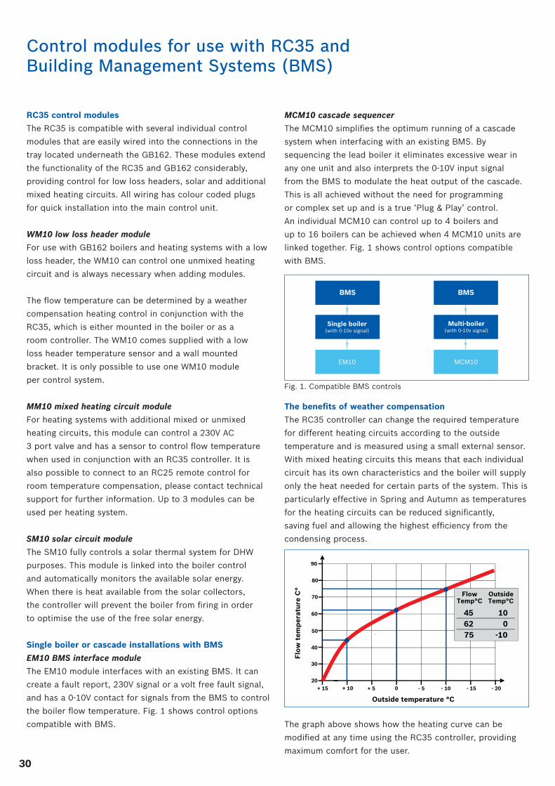
The benefi ts of weather compensation
The RC35 controller can change the required temperature
for different heating circuits according to the outside
temperature and is measured using a small external sensor.
With mixed heating circuits this means that each individual
circuit has its own characteristics and the boiler will supply
only the heat needed for certain parts of the system. This is
particularly effective in Spring and Autumn as temperatures
for the heating circuits can be reduced signifi cantly,
saving fuel and allowing the highest effi ciency from the
condensing process.
The graph above shows how the heating curve can be
modifi ed at any time using the RC35 controller, providing
maximum comfort for the user.
Outside temperature °C
Flo
w t
emp
erat
ure
C°
50
60
90
70
80
40
30
20+ 15 + 10 + 5 0 - 5 - 10 - 15 - 20
45 10
FlowTemp°C
OutsideTemp°C
62 0 75 -10
BMSBMS
Single boiler(with 0-10v signal)
Multi-boiler(with 0-10v signal)
EM10 MCM10
Fig. 1. Compatible BMS controls
3131
The 4000 series modular digital boiler control units secure the safe function of the boilers and allow for the optimum
control of the heating system. The 4121 comes supplied with a MEC2 digital programmer with clear text display which
provides external weather compensated heating control, perfect for maximising the condensing effi ciency of the boilers.
The 4122 control unit can house any of the additional control modules listed, dependent on system requirements.
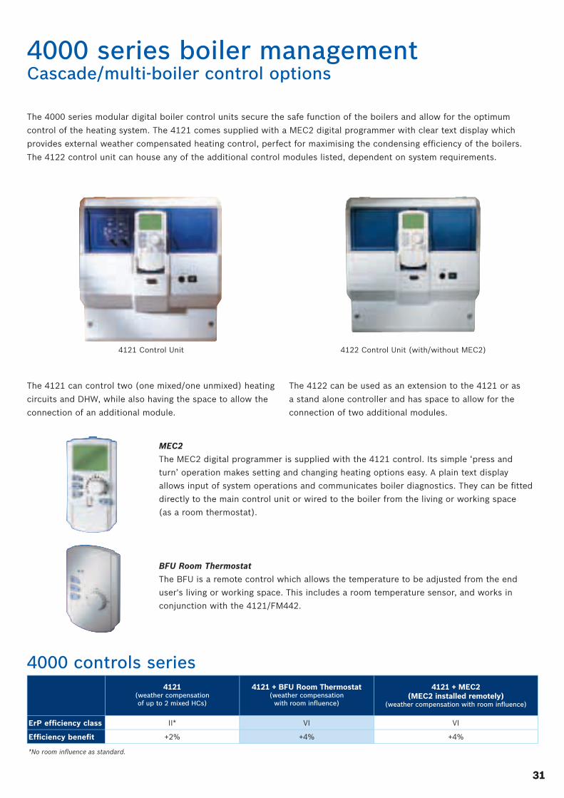
4121 Control Unit
The 4121 can control two (one mixed/one unmixed) heating
circuits and DHW, while also having the space to allow the
connection of an additional module.
4122 Control Unit (with/without MEC2)
The 4122 can be used as an extension to the 4121 or as
a stand alone controller and has space to allow for the
connection of two additional modules.
MEC2
The MEC2 digital programmer is supplied with the 4121 control. Its simple ‘press and
turn’ operation makes setting and changing heating options easy. A plain text display
allows input of system operations and communicates boiler diagnostics. They can be fi tted
directly to the main control unit or wired to the boiler from the living or working space
(as a room thermostat).
BFU Room Thermostat
The BFU is a remote control which allows the temperature to be adjusted from the end
user's living or working space. This includes a room temperature sensor, and works in
conjunction with the 4121/FM442.
4000 series boiler managementCascade/multi-boiler control options
4121(weather compensation of up to 2 mixed HCs)
4121 + BFU Room Thermostat(weather compensation
with room infl uence)
4121 + MEC2 (MEC2 installed remotely)
(weather compensation with room infl uence)
ErP effi ciency class II* VI VI
Effi ciency benefi t +2% +4% +4%
*No room infl uence as standard.
4000 controls series
32
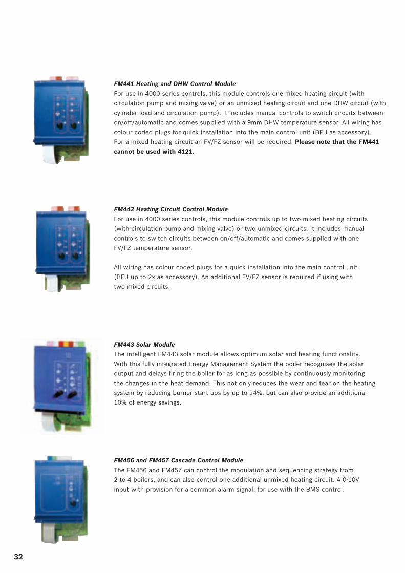
FM441 Heating and DHW Control Module
For use in 4000 series controls, this module controls one mixed heating circuit (with
circulation pump and mixing valve) or an unmixed heating circuit and one DHW circuit (with
cylinder load and circulation pump). It includes manual controls to switch circuits between
on/off/automatic and comes supplied with a 9mm DHW temperature sensor. All wiring has
colour coded plugs for quick installation into the main control unit (BFU as accessory).
For a mixed heating circuit an FV/FZ sensor will be required. Please note that the FM441
cannot be used with 4121.
FM442 Heating Circuit Control Module
For use in 4000 series controls, this module controls up to two mixed heating circuits
(with circulation pump and mixing valve) or two unmixed circuits. It includes manual
controls to switch circuits between on/off/automatic and comes supplied with one
FV/FZ temperature sensor.
All wiring has colour coded plugs for a quick installation into the main control unit
(BFU up to 2x as accessory). An additional FV/FZ sensor is required if using with
two mixed circuits.
FM443 Solar Module
The intelligent FM443 solar module allows optimum solar and heating functionality.
With this fully integrated Energy Management System the boiler recognises the solar
output and delays fi ring the boiler for as long as possible by continuously monitoring
the changes in the heat demand. This not only reduces the wear and tear on the heating
system by reducing burner start ups by up to 24%, but can also provide an additional
10% of energy savings.
FM456 and FM457 Cascade Control Module
The FM456 and FM457 can control the modulation and sequencing strategy from
2 to 4 boilers, and can also control one additional unmixed heating circuit. A 0-10V
input with provision for a common alarm signal, for use with the BMS control.
33
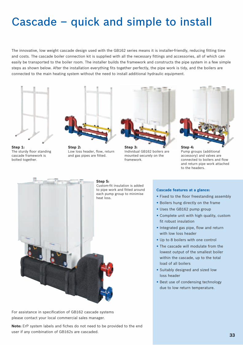
The innovative, low weight cascade design used with the GB162 series means it is installer-friendly, reducing fi tting time
and costs. The cascade boiler connection kit is supplied with all the necessary fi ttings and accessories, all of which can
easily be transported to the boiler room. The installer builds the framework and constructs the pipe system in a few simple
steps as shown below. After the installation everything fi ts together perfectly, the pipe work is tidy, and the boilers are
connected to the main heating system without the need to install additional hydraulic equipment.
Cascade – quick and simple to install
Step 1:The sturdy fl oor standing cascade framework is bolted together.
Step 2:Low loss header, fl ow, return and gas pipes are fi tted.
Step 3:Individual GB162 boilers are mounted securely on the framework.
Step 4:Pump groups (additional accessory) and valves are connected to boilers and fl ow and return pipe work attached to the headers.
Step 5:Custom-fi t insulation is added to pipe work and fi tted around each pump group to minimise heat loss.
Cascade features at a glance:
• Fixed to the fl oor freestanding assembly
• Boilers hung directly on the frame
• Uses the GB162 pump group
• Complete unit with high quality, custom
fi t robust insulation
• Integrated gas pipe, fl ow and return
with low loss header
• Up to 8 boilers with one control
• The cascade will modulate from the
lowest output of the smallest boiler
within the cascade, up to the total
load of all boilers
• Suitably designed and sized low
loss header
• Best use of condensing technology
due to low return temperature.
For assistance in specifi cation of GB162 cascade systems
please contact your local commercial sales manager.
33
Note: ErP system labels and fi ches do not need to be provided to the end
user if any combination of GB162s are cascaded.
34
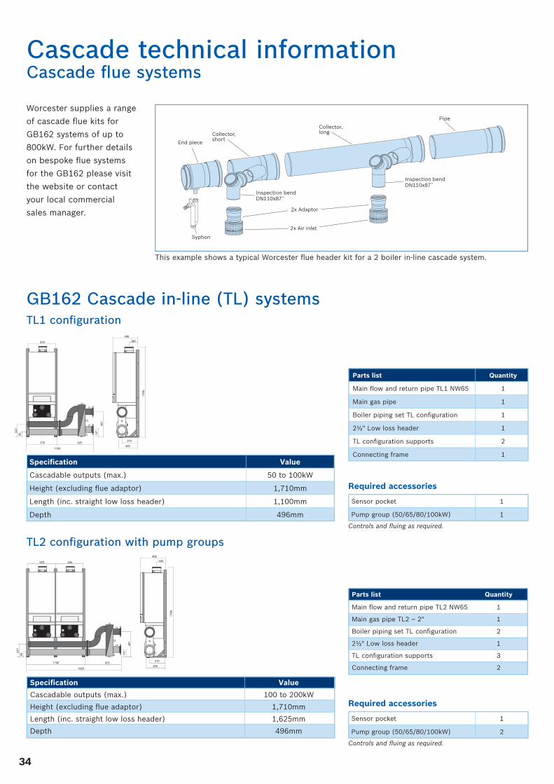
Cascade technical informationCascade fl ue systems
Worcester supplies a range
of cascade fl ue kits for
GB162 systems of up to
800kW. For further details
on bespoke fl ue systems
for the GB162 please visit
the website or contact
your local commercial
sales manager.
Collector,short
Collector,long
Pipe
Inspection bendDN110x87˚
Inspection bendDN110x87˚
Syphon
2x Adaptor
2x Air inlet
End piece
This example shows a typical Worcester fl ue header kit for a 2 boiler in-line cascade system.
180
496
1766
310
405
525
497
147
9224
7
525575
1100
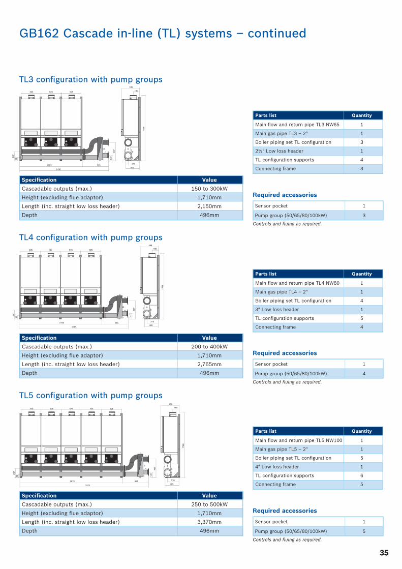
TL1 confi guration
GB162 Cascade in-line (TL) systems
Required accessories
Controls and fl uing as required.
Sensor pocket 1
Pump group (50/65/80/100kW) 1
Parts list Quantity
Main fl ow and return pipe TL1 NW65 1
Main gas pipe 1
Boiler piping set TL confi guration 1
2½" Low loss header 1
TL confi guration supports 2
Connecting frame 1Specifi cation Value
Cascadable outputs (max.) 50 to 100kW
Height (excluding fl ue adaptor) 1,710mm
Length (inc. straight low loss header) 1,100mm
Depth 496mm
TL2 confi guration with pump groups180
496
1766
310
405
525525
497
147
9224
7
5251100
1625
Specifi cation Value
Cascadable outputs (max.) 100 to 200kW
Height (excluding fl ue adaptor) 1,710mm
Length (inc. straight low loss header) 1,625mm
Depth 496mm
Parts list Quantity
Main fl ow and return pipe TL2 NW65 1
Main gas pipe TL2 – 2" 1
Boiler piping set TL confi guration 2
2½" Low loss header 1
TL confi guration supports 3
Connecting frame 2
Required accessories
Controls and fl uing as required.
Sensor pocket 1
Pump group (50/65/80/100kW) 2
3535
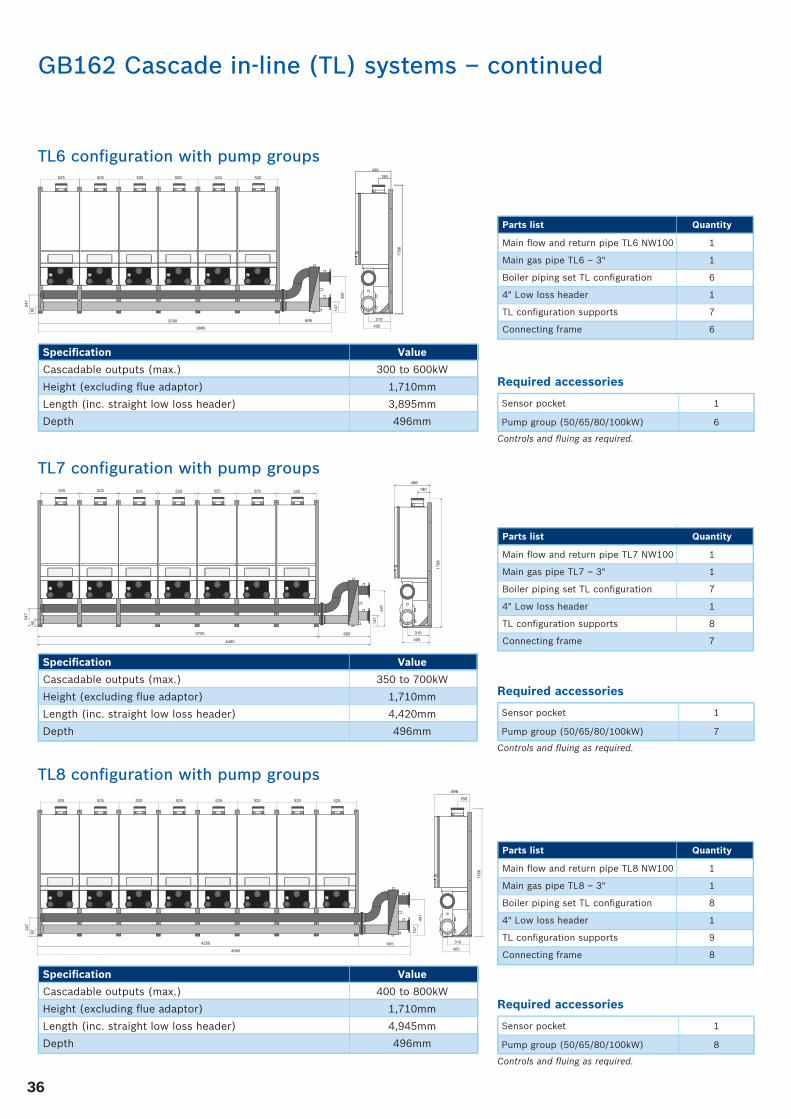
TL4 confi guration with pump groups
6152150
525525 525
2765
497
147
180
496
1766
310
405
9224
7
525
TL3 confi guration with pump groups525525525
497
147
9224
7
5251625
2150
180
496
1766
310
405
Specifi cation Value
Cascadable outputs (max.) 150 to 300kW
Height (excluding fl ue adaptor) 1,710mm
Length (inc. straight low loss header) 2,150mm
Depth 496mm
Parts list Quantity
Main fl ow and return pipe TL3 NW65 1
Main gas pipe TL3 – 2" 1
Boiler piping set TL confi guration 3
2½" Low loss header 1
TL confi guration supports 4
Connecting frame 3
Specifi cation Value
Cascadable outputs (max.) 200 to 400kW
Height (excluding fl ue adaptor) 1,710mm
Length (inc. straight low loss header) 2,765mm
Depth 496mm
Parts list Quantity
Main fl ow and return pipe TL4 NW80 1
Main gas pipe TL4 – 2" 1
Boiler piping set TL confi guration 4
3" Low loss header 1
TL confi guration supports 5
Connecting frame 4
TL5 confi guration with pump groups180
496
1766
310
4056952675
525525 525
3370
147
525
92
247
525
497
Specifi cation Value
Cascadable outputs (max.) 250 to 500kW
Height (excluding fl ue adaptor) 1,710mm
Length (inc. straight low loss header) 3,370mm
Depth 496mm
Parts list Quantity
Main fl ow and return pipe TL5 NW100 1
Main gas pipe TL5 – 2" 1
Boiler piping set TL confi guration 5
4" Low loss header 1
TL confi guration supports 6
Connecting frame 5
GB162 Cascade in-line (TL) systems – continued
Required accessories
Controls and fl uing as required.
Sensor pocket 1
Pump group (50/65/80/100kW) 3
Required accessories
Controls and fl uing as required.
Sensor pocket 1
Pump group (50/65/80/100kW) 4
Required accessories
Controls and fl uing as required.
Sensor pocket 1
Pump group (50/65/80/100kW) 5
36
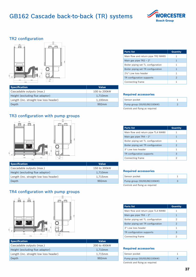
TL6 confi guration with pump groups180
496
1766
310
4056953200
525525 525
3895
147
525
9224
7
525525
497
180496
1766
310
4056954250
525525 525
4945
147
525525
497
525525
92
525
247
Specifi cation Value
Cascadable outputs (max.) 300 to 600kW
Height (excluding fl ue adaptor) 1,710mm
Length (inc. straight low loss header) 3,895mm
Depth 496mm
Parts list Quantity
Main fl ow and return pipe TL6 NW100 1
Main gas pipe TL6 – 3" 1
Boiler piping set TL confi guration 6
4" Low loss header 1
TL confi guration supports 7
Connecting frame 6
Specifi cation Value
Cascadable outputs (max.) 400 to 800kW
Height (excluding fl ue adaptor) 1,710mm
Length (inc. straight low loss header) 4,945mm
Depth 496mm
Parts list Quantity
Main fl ow and return pipe TL8 NW100 1
Main gas pipe TL8 – 3" 1
Boiler piping set TL confi guration 8
4" Low loss header 1
TL confi guration supports 9
Connecting frame 8
TL8 confi guration with pump groups
Required accessories
Controls and fl uing as required.
Sensor pocket 1
Pump group (50/65/80/100kW) 6
180
496
1766
310
4056953725
525525 525
4420
147
525525
497
525
92
247
525
Specifi cation Value
Cascadable outputs (max.) 350 to 700kW
Height (excluding fl ue adaptor) 1,710mm
Length (inc. straight low loss header) 4,420mm
Depth 496mm
Parts list Quantity
Main fl ow and return pipe TL7 NW100 1
Main gas pipe TL7 – 3" 1
Boiler piping set TL confi guration 7
4" Low loss header 1
TL confi guration supports 8
Connecting frame 7
TL7 confi guration with pump groups
Required accessories
Controls and fl uing as required.
Sensor pocket 1
Pump group (50/65/80/100kW) 7
Required accessories
Controls and fl uing as required.
Sensor pocket 1
Pump group (50/65/80/100kW) 8
GB162 Cascade in-line (TL) systems – continued
3737
TR3 confi guration with pump groups360
992
1766
310
405
525525
497
92
247
1100
1715
615
147
TR2 confi guration360
992
1766
310
405
525
497
147
92
247
525575
1100
Specifi cation Value
Cascadable outputs (max.) 100 to 200kW
Height (excluding fl ue adaptor) 1,710mm
Length (inc. straight low loss header) 1,100mm
Depth 992mm
GB162 Cascade back-to-back (TR) systems
Specifi cation Value
Cascadable outputs (max.) 150 to 300kW
Height (excluding fl ue adaptor) 1,710mm
Length (inc. straight low loss header) 1,715mm
Depth 992mm
Parts list Quantity
Main fl ow and return pipe TL4 NW80 1
Main gas pipe TR4 – 2" 1
Boiler piping set TL confi guration 1
Boiler piping set TR confi guration 2
3" Low loss header 1
TR confi guration supports 3
Connecting frame 2
Parts list Quantity
Main fl ow and return pipe TR2 NW65 1
Main gas pipe TR2 – 2" 1
Boiler piping set TL confi guration 1
Boiler piping set TR confi guration 1
2½" Low loss header 1
TR confi guration supports 2
Connecting frame 1
TR4 confi guration with pump groups360
992
1766
310
405
525525
497
92
247
1100
1715
615
147
Specifi cation Value
Cascadable outputs (max.) 200 to 400kW
Height (excluding fl ue adaptor) 1,710mm
Length (inc. straight low loss header) 1,715mm
Depth 992mm
Parts list Quantity
Main fl ow and return pipe TL4 NW80 1
Main gas pipe TR4 – 2" 1
Boiler piping set TL confi guration 2
Boiler piping set TR confi guration 2
3" Low loss header 1
TR confi guration supports 3
Connecting frame 2
Required accessories
Controls and fl uing as required.
Sensor pocket 1
Pump group (50/65/80/100kW) 2
Required accessories
Controls and fl uing as required.
Sensor pocket 1
Pump group (50/65/80/100kW) 4
Required accessories
Controls and fl uing as required.
Sensor pocket 1
Pump group (50/65/80/100kW) 3
38
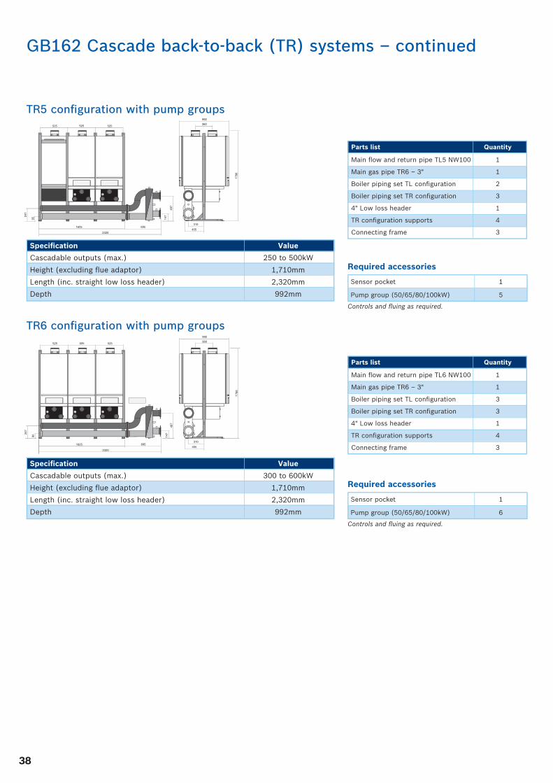
TR5 confi guration with pump groups525525525
497
92
247
1625
2320
360
992
1766
310
405695
147
Specifi cation Value
Cascadable outputs (max.) 250 to 500kW
Height (excluding fl ue adaptor) 1,710mm
Length (inc. straight low loss header) 2,320mm
Depth 992mm
Parts list Quantity
Main fl ow and return pipe TL5 NW100 1
Main gas pipe TR6 – 3" 1
Boiler piping set TL confi guration 2
Boiler piping set TR confi guration 3
4" Low loss header 1
TR confi guration supports 4
Connecting frame 3
TR6 confi guration with pump groups525525525
497
92
247
1625
2320
360
992
1766
310
405695
147
Specifi cation Value
Cascadable outputs (max.) 300 to 600kW
Height (excluding fl ue adaptor) 1,710mm
Length (inc. straight low loss header) 2,320mm
Depth 992mm
Parts list Quantity
Main fl ow and return pipe TL6 NW100 1
Main gas pipe TR6 – 3" 1
Boiler piping set TL confi guration 3
Boiler piping set TR confi guration 3
4" Low loss header 1
TR confi guration supports 4
Connecting frame 3
Required accessories
Controls and fl uing as required.
Sensor pocket 1
Pump group (50/65/80/100kW) 5
Required accessories
Controls and fl uing as required.
Sensor pocket 1
Pump group (50/65/80/100kW) 6
GB162 Cascade back-to-back (TR) systems – continued
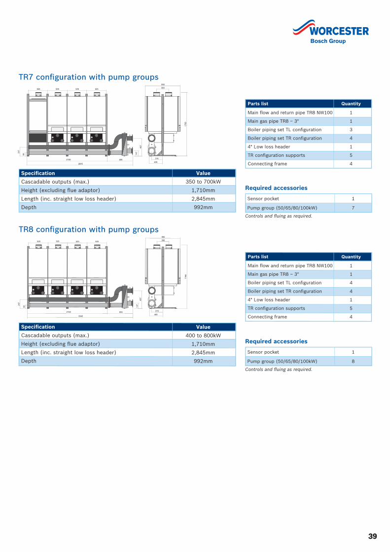
3939
TR7 confi guration with pump groups360
992
1766
310
4052150
525525 525
2845
497
92
247
525
695
147
Specifi cation Value
Cascadable outputs (max.) 350 to 700kW
Height (excluding fl ue adaptor) 1,710mm
Length (inc. straight low loss header) 2,845mm
Depth 992mm
Parts list Quantity
Main fl ow and return pipe TR8 NW100 1
Main gas pipe TR8 – 3" 1
Boiler piping set TL confi guration 3
Boiler piping set TR confi guration 4
4" Low loss header 1
TR confi guration supports 5
Connecting frame 4
TR8 confi guration with pump groups360
992
1766
310
4052150
525525 525
2845
497
92
247
525
695
147
Specifi cation Value
Cascadable outputs (max.) 400 to 800kW
Height (excluding fl ue adaptor) 1,710mm
Length (inc. straight low loss header) 2,845mm
Depth 992mm
Parts list Quantity
Main fl ow and return pipe TR8 NW100 1
Main gas pipe TR8 – 3" 1
Boiler piping set TL confi guration 4
Boiler piping set TR confi guration 4
4" Low loss header 1
TR confi guration supports 5
Connecting frame 4
Required accessories
Controls and fl uing as required.
Sensor pocket 1
Pump group (50/65/80/100kW) 7
Required accessories
Controls and fl uing as required.
Sensor pocket 1
Pump group (50/65/80/100kW) 8

40
GB162 boiler series and accessories
GB16265kW
Worcester Part No. 7 746 900 822
GB16250kW
Worcester Part No. 7 736 700 642
GB16280kW
Worcester Part No. 8 747 024 8
GB162100kW
Worcester Part No. 8 747 025 0
RC35 digital boiler control
Worcester Part No. 7 747 312 318
RC25 room thermostat(max 2 per system)
Worcester Part No. 7 747 312 367
WM10 low loss header module
Worcester Part No. 30 008 458
MM10 mixed heating circuit module
Worcester Part No. 30 008 453
SM10 solar module
Worcester Part No. 30 008 448
EM10 BMS interface for single boilers
Worcester Part No. 5 016 995
MCM10 cascade sequencing control for up to 4 boilers
Worcester Part No. 7 746 900 847
RC series boiler & system controls
GB162 boilers
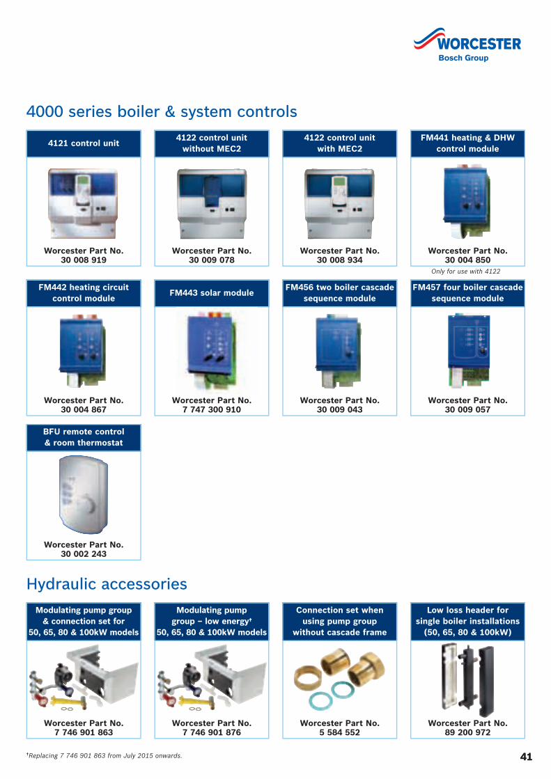
4141
4121 control unit
Worcester Part No. 30 008 919
4122 control unitwithout MEC2
Worcester Part No. 30 009 078
4122 control unitwith MEC2
Worcester Part No. 30 008 934
4000 series boiler & system controls
BFU remote control & room thermostat
Worcester Part No. 30 002 243
FM443 solar module
Worcester Part No. 7 747 300 910
FM456 two boiler cascade sequence module
Worcester Part No. 30 009 043
FM457 four boiler cascade sequence module
Worcester Part No. 30 009 057
FM442 heating circuit control module
Worcester Part No. 30 004 867
FM441 heating & DHW control module
Worcester Part No. 30 004 850
Only for use with 4122
Modulating pump group & connection set for
50, 65, 80 & 100kW models
Worcester Part No. 7 746 901 863
Modulating pump group – low energy†
50, 65, 80 & 100kW models
Worcester Part No. 7 746 901 876
Connection set when using pump group
without cascade frame
Worcester Part No. 5 584 552
Low loss header for single boiler installations
(50, 65, 80 & 100kW)
Worcester Part No. 89 200 972
Hydraulic accessories
†Replacing 7 746 901 863 from July 2015 onwards.
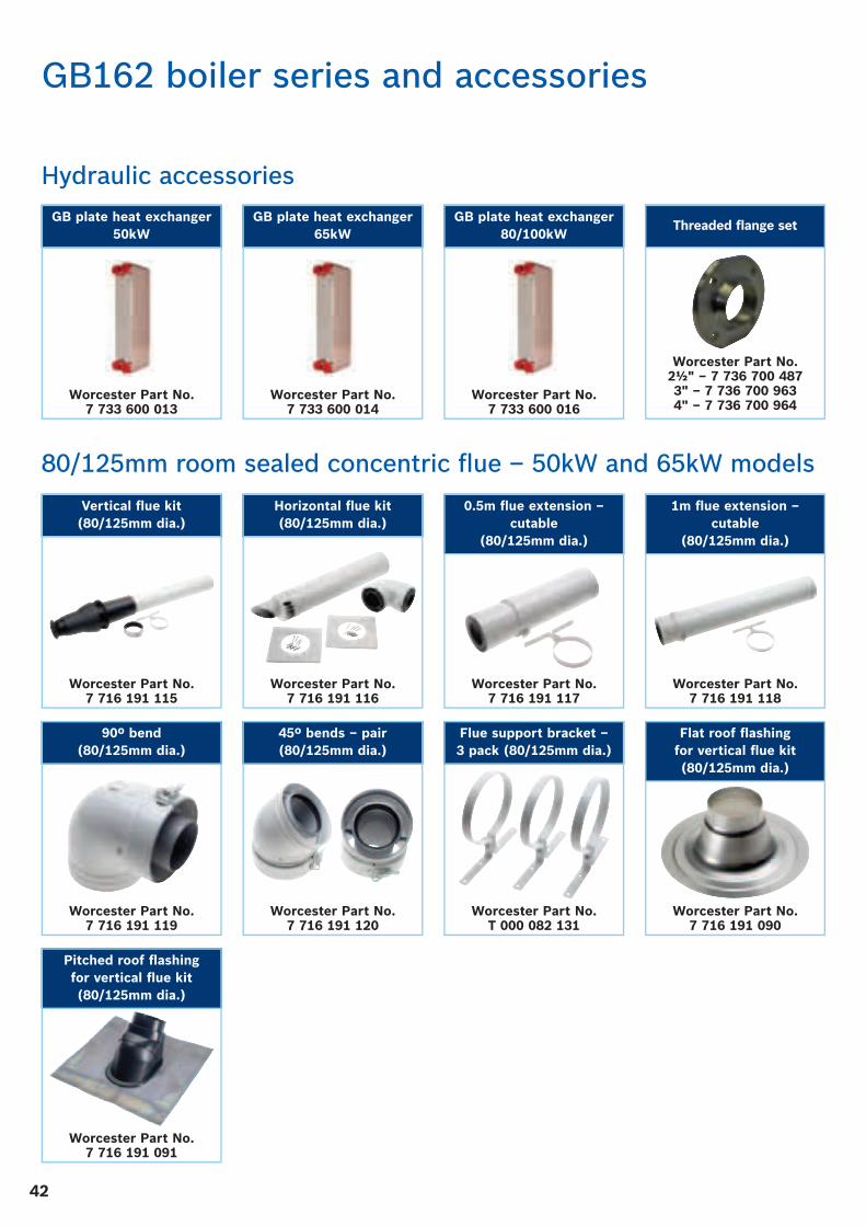
42
80/125mm room sealed concentric fl ue – 50kW and 65kW models
Pitched roof fl ashingfor vertical fl ue kit(80/125mm dia.)
Worcester Part No. 7 716 191 091
45º bends – pair(80/125mm dia.)
Worcester Part No. 7 716 191 120
90º bend(80/125mm dia.)
Worcester Part No. 7 716 191 119
Flue support bracket –3 pack (80/125mm dia.)
Worcester Part No. T 000 082 131
Flat roof fl ashingfor vertical fl ue kit(80/125mm dia.)
Worcester Part No. 7 716 191 090
GB162 boiler series and accessories
Hydraulic accessories
Vertical fl ue kit(80/125mm dia.)
Worcester Part No. 7 716 191 115
0.5m fl ue extension –cutable
(80/125mm dia.)
Worcester Part No. 7 716 191 117
Horizontal fl ue kit(80/125mm dia.)
Worcester Part No. 7 716 191 116
1m fl ue extension –cutable
(80/125mm dia.)
Worcester Part No. 7 716 191 118
Threaded fl ange set
Worcester Part No. 2½" – 7 736 700 4873" – 7 736 700 9634" – 7 736 700 964
GB plate heat exchanger80/100kW
Worcester Part No. 7 733 600 016
GB plate heat exchanger65kW
Worcester Part No. 7 733 600 014
GB plate heat exchanger50kW
Worcester Part No. 7 733 600 013

4343
Horizontal fl ue kit(100/150mm dia.)
Worcester Part No. 7 716 191 094
Vertical fl ue kit(100/150mm dia.)
Worcester Part No. 7 716 191 093
0.5m fl ue extension – cutable (100/150mm dia.)
Worcester Part No. 7 716 191 095
Adaptor for GB162 50kW and 65kW only (100/150mm dia.)
Worcester Part No. 7 746 901 750
Clamp with EPDM seal (100/150mm dia.)
Worcester Part No. 7 716 191 103
Pitched roof fl ashing(100/150mm dia.)
Worcester Part No. 7 716 191 100
Flat roof fl ashing(100/150mm dia.)
Worcester Part No. 7 716 191 101
Flue support bracket – 3 pack (100/150mm dia.)
Worcester Part No. 7 716 191 102
1m fl ue extension – non-cutable
(100/150mm dia.)
Worcester Part No. 7 716 191 097
45º bends – pair(100/150mm dia.)
Worcester Part No. 7 716 191 099
90º bend(100/150mm dia.)
Worcester Part No. 7 716 191 098
1m fl ue extension – cutable
(100/150mm dia.)
Worcester Part No. 7 716 191 096
100/150mm room sealed concentric fl ue – 50, 65, 80 & 100kW models
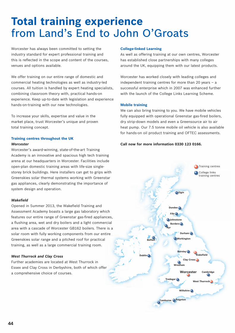
44
Total training experience from Land’s End to John O’Groats
Belfast
Wakefield
Clay Cross
Worcester
West Thurrock
Dundee
Fife
Dublin
Burnley
Durham
Wiltshire
Tredegar
Cambridge
Wrexham
Camborne Paignton
Johnstone
Borders
Elgin
Ayr
Workington
WWWWWWWWWWWWWWWWWWW
Worcester has always been committed to setting the
industry standard for expert professional training and
this is refl ected in the scope and content of the courses,
venues and options available.
We offer training on our entire range of domestic and
commercial heating technologies as well as industry-led
courses. All tuition is handled by expert heating specialists,
combining classroom theory with, practical hands-on
experience. Keep up-to-date with legislation and experience
hands-on-training with our new technologies.
To increase your skills, expertise and value in the
market place, trust Worcester’s unique and proven
total training concept.
Training centres throughout the UK
Worcester
Worcester’s award-winning, state-of-the-art Training
Academy is an innovative and spacious high tech training
arena at our headquarters in Worcester. Facilities include
open-plan domestic training areas with life-size single-
storey brick buildings. Here installers can get to grips with
Greenskies solar thermal systems working with Greenstar
gas appliances, clearly demonstrating the importance of
system design and operation.
Wakefi eld
Opened in Summer 2013, the Wakefi eld Training and
Assessment Academy boasts a large gas laboratory which
features our entire range of Greenstar gas-fi red appliances,
a fl ushing area, wet and dry boilers and a light commercial
area with a cascade of Worcester GB162 boilers. There is a
solar room with fully working components from our entire
Greenskies solar range and a pitched roof for practical
training, as well as a large commercial training room.
West Thurrock and Clay Cross
Further academies are located at West Thurrock in
Essex and Clay Cross in Derbyshire, both of which offer
a comprehensive choice of courses.
College-linked Learning
As well as offering training at our own centres, Worcester
has established close partnerships with many colleges
around the UK, equipping them with our latest products.
Worcester has worked closely with leading colleges and
independent training centres for more than 20 years – a
successful enterprise which in 2007 was enhanced further
with the launch of the College Links Learning Scheme.
Mobile training
We can also bring training to you. We have mobile vehicles
fully equipped with operational Greenstar gas-fi red boilers,
dry strip-down models and even a Greensource air to air
heat pump. Our 7.5 tonne mobile oil vehicle is also available
for hands-on oil product training and OFTEC assessments.
Call now for more information 0330 123 0166.
Training centresT
College links training centres
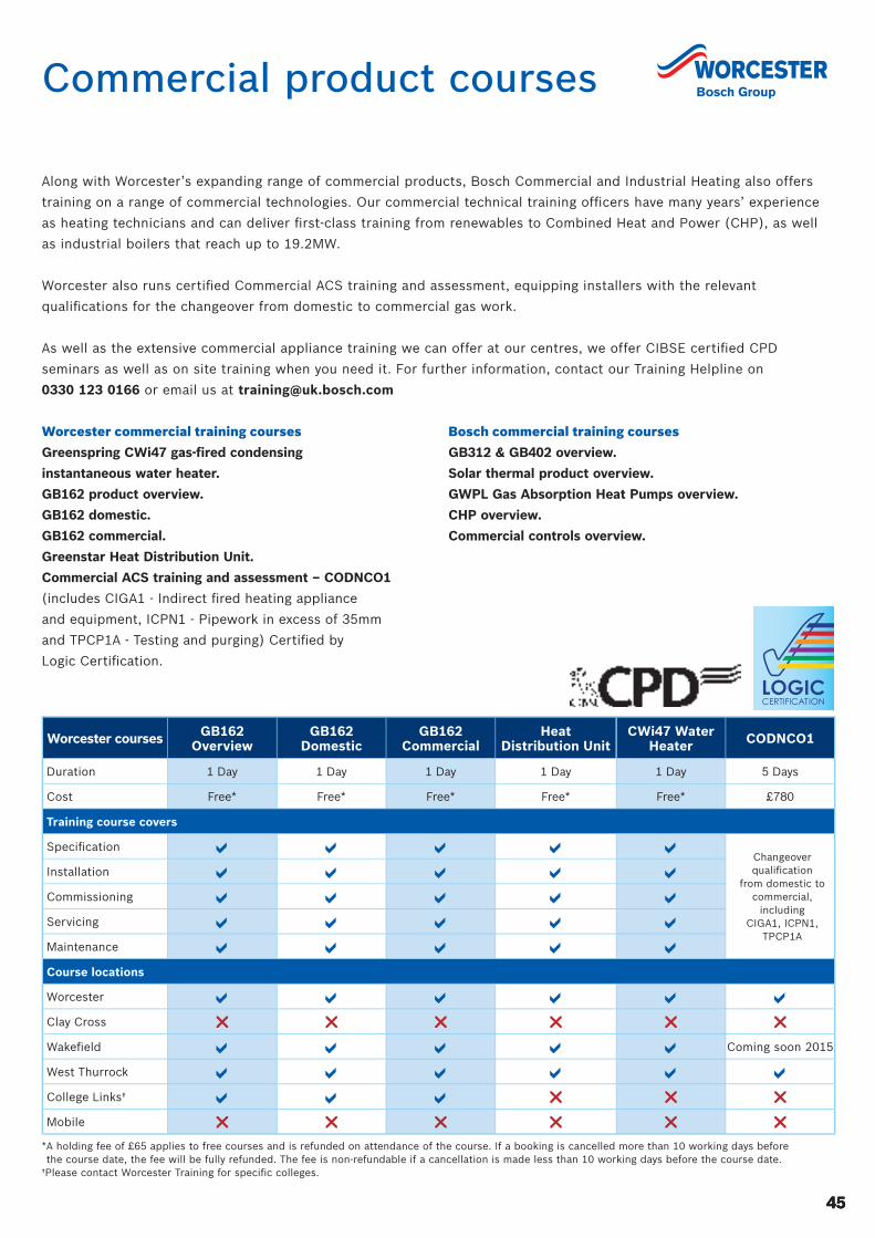
45
Commercial product courses
4545
Along with Worcester’s expanding range of commercial products, Bosch Commercial and Industrial Heating also offers
training on a range of commercial technologies. Our commercial technical training offi cers have many years’ experience
as heating technicians and can deliver fi rst-class training from renewables to Combined Heat and Power (CHP), as well
as industrial boilers that reach up to 19.2MW.
Worcester also runs certifi ed Commercial ACS training and assessment, equipping installers with the relevant
qualifi cations for the changeover from domestic to commercial gas work.
As well as the extensive commercial appliance training we can offer at our centres, we offer CIBSE certifi ed CPD
seminars as well as on site training when you need it. For further information, contact our Training Helpline on
0330 123 0166 or email us at [email protected]
Worcester commercial training courses
Greenspring CWi47 gas-fi red condensing
instantaneous water heater.
GB162 product overview.
GB162 domestic.
GB162 commercial.
Greenstar Heat Distribution Unit.
Commercial ACS training and assessment – CODNCO1
(includes CIGA1 - Indirect fi red heating appliance
and equipment, ICPN1 - Pipework in excess of 35mm
and TPCP1A - Testing and purging) Certifi ed by
Logic Certifi cation.
Bosch commercial training courses
GB312 & GB402 overview.
Solar thermal product overview.
GWPL Gas Absorption Heat Pumps overview.
CHP overview.
Commercial controls overview.
Worcester courses GB162 Overview
GB162 Domestic
GB162 Commercial
Heat Distribution Unit
CWi47 Water Heater CODNCO1
Duration 1 Day 1 Day 1 Day 1 Day 1 Day 5 Days
Cost Free* Free* Free* Free* Free* £780
Training course covers
Specifi cationChangeover qualifi cation
from domestic to commercial,
including CIGA1, ICPN1,
TPCP1A
Installation
Commissioning
Servicing
Maintenance
Course locations
Worcester
Clay Cross
Wakefi eld Coming soon 2015
West Thurrock
College Links†
Mobile
* A holding fee of £65 applies to free courses and is refunded on attendance of the course. If a booking is cancelled more than 10 working days before the course date, the fee will be fully refunded. The fee is non-refundable if a cancellation is made less than 10 working days before the course date.
†Please contact Worcester Training for specifi c colleges.

Additional product and industry training courses The diversity of products in today’s heating industry gives you the opportunity to expand your expertise, whilst offering
more choice to your customers. Worcester provides comprehensive training from all its academies on its entire range of
technologies. Call us on 0330 123 0166 to order a full course training brochure or to book yourself onto a training course,
alternatively, you can visit www.worcester-bosch.co.uk/training
Gas-fired condensing boiler courses
• Greenstar CDi Classic gas-fi red condensing
combi boilers.
• Greenstar CDi Compact and Greenstar Si Compact
gas-fi red condensing combi boilers.
• Greenstar i gas-fi red condensing combi boilers.
• Greenstar system & regular gas-fi red condensing boilers.
• Greenstar Highfl ow CDi & FS CDi Regular fl oor standing
gas-fi red condensing combi and regular boilers.
• Greenstar Controls (covers MT10, MT10RF,
NEW Greenstar Comfort range, NEW Wave internet
connected room thermostat, FR10, FR110, FW100,
and solar controls).
Oil-fi red product courses
• Greenstar Danesmoor & Heatslave II high effi ciency
condensing oil-fi red boilers.
• Oil advanced fault fi nding.
• OFTEC 50.
• OFTEC 101/105e, OFTEC 600a and OFTEC
101/105e/600a.
Renewable product courses
• Renewables overview.
• Greenskies solar.
• Greenskies advanced solar.
• Introduction to heat pumps.
• Greenstore LECP ground source heat pumps.
• Greensource air to air heat pumps.
Industry focused courses
• Hot water systems & safety.
• Chemical water treatment.
• Construction skills F-Gas training/assessment
certifi cation.
• IDHEE domestic heating design.
• Domestic ACS training and assessment – reassessment.
CCN1 + 3 appliances.
• QCF Level 3 Award
– Air source and ground source heat pumps.
– Air to water and split air to water heat pumps.
– Solar thermal.
• MCS Made Easy.
• Green Deal.
• LPG Changeover.
• WRAS Water Regulations.
46

47
A complete after-sales service
Spares
Genuine replacement parts for all supported Worcester
products are readily available from stock, or on a next day
delivery basis. Visit www.worcester-bosch.co.uk/spares
to fi nd your local stockist.
Customer Technical Support
The Worcester Technical Helpline is a dedicated phone
line – committed to providing a comprehensive service to
complement the brand name and quality of our products.
Our experienced team of technical experts provides
answers to queries of a technical nature across the entire
Worcester range.
Technical Support
Tel: 0330 123 3366
Fax: 01905 752 741
Email: [email protected]
Opening times
Monday – Friday: 7.00am – 8.00pm
Saturday: 8.30am – 4.00pm
Bank Holidays: 8.00am – 4.30pm
ErP Technical Helpline
Tel: 0330 123 3641
Email: [email protected]
As part of the worldwide Bosch Group, Worcester strives to
maintain the highest possible standards of after-sales care.
Worcester Contact Centre
Should you require support, our award winning Contact
Centre team, based at our head offi ce in Worcester, are
ready to take your calls. Whatever your query our contact
centre operators along with our nationwide team of
engineers are ready to help you.
Tel: 0330 123 9559
Opening times
Monday – Friday: 7.00am – 8.00pm
Saturday: 8.00am – 5.00pm
Sunday: 9.00am – 12 noon
Bank Holidays: 8.00am – 4.30pm
47

worcester-bosch.co.uk
Worcester, Bosch Group,
Cotswold Way, Warndon,
Worcester, WR4 9SW
BB
T3588
Calls to 03 numbers cost no more than a national rate call to an 01 or 02 number and must count towards any inclusive minutes in the same way as 01 and 02 calls.
These rules apply to calls from any type of line, including mobile, BT, other fi xed phone line or payphone. Calls from mobiles and some other networks may vary.
Calls to and from Bosch Thermotechnology Ltd may be recorded for training and quality assurance purposes.
Engineer Appointments
Email: [email protected]
or telephone 0330 123 9339
Service Enquiries
Email: [email protected]
or telephone 0330 123 9559
Guarantee Registration
To register your Worcester guarantee,
please visit our website
www.worcester-bosch.co.uk/registration,
download our guarantee
registration app or
telephone 0330 123 2552
Customer ServiceSales
Tel: 0330 123 9669
Spare Parts
Tel: 0330 123 9779
Technical Helpline (Pre & Post Sales)
Tel: 0330 123 3366
Renewables Technical Helpline
Email: [email protected]
or telephone 0330 123 9229
ErP Technical Helpline
Tel: 0330 123 3641
Training
Tel: 0330 123 0166
Literature
Email: [email protected]
or download instantly from our website
or telephone 0330 123 9119
Useful numbers
Worcester, Bosch Group is a brand name of Bosch Thermotechnology Ltd.
This leafl et is accurate at the date of printing, but may be superseded and should be disregarded if specifi cation and/or appearances are changed in the interest of continued improvement. The statutory rights of the consumer are not affected. Apple is a trademark of Apple Inc., registered in the U.S. and other countries. App Store is a service mark of Apple Inc. Google Play and Android are trademarks of Google Inc.
Part No. 8 716 111 872 D 05/15PAPERS MADE WITH
100% CHLORINE FREEBLEACHED PULPTM
In partnership with
D EEI
H
INSTITUTE
OF D
OMES
TIC HEATING & ENVIRONMENTAL ENGINEERS
1 9 6 4
Guarantee app