Embed Size (px)
Citation preview

High performance gas-fired wall-mounted boileroperating and installation instructionsGB
2C607215 - GBINSTRUCTIONS FOR USERS
Dear Customer,We are confident your new boiler will meet all your requirements.All BAXI products have been designed to give you what you are looking for: good performance combined with simple and rational use.Please do not put away this booklet without reading it first as it contains some useful information which will help you to operate your boiler correctly and efficiently.
Do not leave any packaging (plastic bags, polystyrene, etc.) within the reach of children as they are a potential source of danger
BAXI S.p.A. declares that these models of boiler bear the CE mark in compliance with the basic require-ments of the following Directives: - Gas Directive 90/396/EEC- Efficiency Directive 92/42/EEC- Electromagnetic Compatibility Directive 2004/108/EEC- Low Voltage Directive 2006/95/EC
1. Instructions prior to installation 32. Instructions prior to commissioning 33. Commissioning the boiler 44. Special functions 95. Filling the system 116. Turning off the boiler 127. Gas conversion 128. Prolonged shutdown. Frost protection 129. Troubleshooting 1210. Routine maintenance instructions 13
11. General information 1412. Instructions prior to installation 1413. Installing the boiler 1514. Dimensions of boiler 1515. Contents of pack 1616. Installation of flue and air ducts 1617. Connecting the mains supply 2018. Installing the climate controller 2119. Gas conversion methods 2320. Visualisation of electronic board parameters on boiler display (“info” function) 2521. Parameters setting 2722. Adjustment and safety devices 2823. Positioning the ignition and flame-sensor electrode 2924. Checking combustion parameters 2925. Output/pump head performance 3026. Draining the storage boiler 3027. Connection of an external storage boiler 3128. Electrical connection to a zone system 3329. Annual servicing 3430. Circuit diagram 35-3631. Illustrated wiring diagram 37-3832. Technical data 39
CONTENTS
INSTRUCTIONS FOR USERS
INSTRUCTIONS FOR FITTERS
BAXI S.p.A., a leading European manufacturer of hi-tech boilers and heating systems, has developed CSQ-certified quality management (ISO 9001), environmental (ISO 14001) and health and safety (OHSAS 18001) systems. This means that BAXI S.p.A. includes among its objectives the safeguard of the environment, the reliability and quality of its products, and the health and safety of its employees. Through its organisation, the company is constantly committed to implementing and improving these aspects in favour of customer satisfaction.
3C607215 - GBINSTRUCTIONS FOR USERS
This boiler has been designed to heat water to a temperature lower than boiling point at atmospheric pressure. It must be connected to a central heating system and to a domestic hot water supply system according to its performance and power output.Before having the boiler installed by a qualified service engineer, make sure the following operations are performed:
a) Make sure that the boiler is adjusted to use the type of gas delivered by the gas supply. To do this, check the markings on the packaging and the rating plate on the appliance.
b) Make sure that the flue terminal draft is appropriate, that the terminal is not obstructed and that no exhaust gases from other appliances are expelled through the same flue duct, unless the latter has been specially designed to collect exhaust gas from more than one appliance, in compliance with current laws and regulations.
c) Make sure that, if the boiler is connected to existing flue ducts, these have been thoroughly cleaned as residual products of combustion may detach from the walls during operation and obstruct the flow of fumes.
d) To ensure correct operation and maintain the warranty, observe the following precautions:
1. DHW circuit:
1.1. If the water is harder than 20 °F (1 °F = 10 mg calcium carbonate per litre of water), install a polyphosphate dispenser or an equivalent treatment system, compliant with current regulations.
1.2. Thoroughly flush the system after installation of the appliance and before use.
2. Heating circuit
2.1. new system Before proceeding with installation of the boiler, the system must be cleaned and flushed to eliminate residual thread-cutting
swarf, solder and any solvents, using suitable proprietary products. To avoid damaging metal, plastic and rubber parts, only use neutral cleaners, i.e. non-acid and non alkaline. Recommended cleaning products are: SENTINEL X300 or X400 and FERNOX Regenerator for heating circuits. Use these products in strict compliance with the manufacturers’ instructions.
2.2. existing plant: Before installing the boiler, drain the system and clean it to remove sludge and contaminants, using suitable proprietary products
as described in section 2.1. To avoid damaging metal, plastic and rubber parts, use only neutral cleaners, i.e. non-acid and non-alkaline such as SENTINEL X100 and FERNOX Protector for heating circuits. Use these products in strict compliance with the manufacturers’ instructions. Remember that the presence of foreign bodies in the heating system can adversely affect boiler operation (e.g. overheating and excessive noise of the heat exchanger).
Failure to observe the above will render the guarantee null and void.
1. INSTRUCTIONS PRIOR TO INSTALLATION
Initial lighting of the boiler must be carried out by an authorised Service Engineer who must first ensure that:
a) the rated data correspond to the supply (electricity, water and gas) data; b) the installation complies with current laws and regulations; c) the appliance is correctly connected to the power supply and earthed.
The names of the authorised Service Centres are indicated in the attached sheet. Failure to observe the above will render the guarantee null and void. Prior to commissioning, remove the protective plastic coating from the boiler. Do not use any tools or abrasive detergents to do this as you may damage the painted surfaces.
The instructions shall state the substance of the following:This appliance is not intended for use by persons (including children) with reduced physical, sensory or mental capabilities, or lack of experience and knowledge, unless they have been given supervision or instruction concerning use of the appliance by a person responsible for their safety.Children should be supervised to ensure that they do not play with the appliance.
2. INSTRUCTIONS PRIOR TO COMMISSIONING
4C607215 - GBINSTRUCTIONS FOR USERS
3. COMMISSIONING THE BOILER
To light the boiler correctly, proceed as follows:
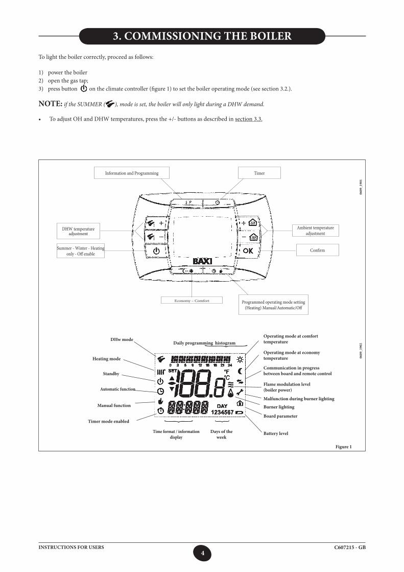
1) power the boiler2) open the gas tap;3) press button on the climate controller (figure 1) to set the boiler operating mode (see section 3.2.).
NOTE: if the SUMMER ( ), mode is set, the boiler will only light during a DHW demand.
• ToadjustOHandDHWtemperatures,pressthe+/-buttonsasdescribedinsection 3.3.
Figure 1
0609
_190
1
Summer - Winter - Heating only - Off enable
DHW temperature adjustment
Information and Programming Timer
Ambient temperature adjustment
Confirm
Programmed operating mode setting (Heating) Manual/Automatic/Off
Economy – Comfort
Daily programming histogramOperating mode at comfort temperature
Operating mode at economy temperature
Communication in progress between board and remote control
Flame modulation level (boiler power)
Malfunction during burner lighting
Burner lighting
Board parameter
Battery levelDays of the week
Time format / information display
DHw mode
Heating mode
Standby
Automatic function
Manual function
Timer mode enabled
0609
_190
2
{ {
{
5C607215 - GBINSTRUCTIONS FOR USERS
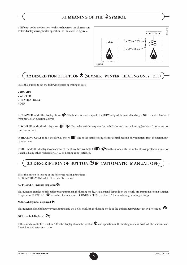
4 different boiler modulation levels are shown on the climate con-troller display during boiler operation, as indicated in figure 2.
0605
_180
2
Figure 2
Press this button to set the following boiler operating modes: • SUMMER• WINTER• HEATING ONLY• OFF
In SUMMER mode, the display shows . The boiler satisfies requests for DHW only while central heating is NOT enabled (ambient frost protection function active).
In WINTER mode, the display shows The boiler satisfies requests for both DHW and central heating (ambient frost protection function active).
In HEATING ONLY mode, the display shows The boiler satisfies requests for central heating only (ambient frost protection fun-ction active).
In OFF mode, the display shows neither of the above two symbols ( ) ( ) In this mode only the ambient frost protection function is enabled, any other request for DHW or heating is not satisfied.
3.2 DESCRIPTION OF BUTTON (SUMMER - WINTER - HEATING ONLY - OFF)
Press this button to set one of the following heating functions:AUTOMATIC-MANUAL-OFF as described below.
AUTOMATIC (symbol displayed )
This function enables hourly boiler programming in the heating mode. Heat demand depends on the hourly programming setting (ambient temperature COMFORT “ ” or ambient temperature ECONOMY “ ” See section 3.6 for hourly programming settings.
MANUAL (symbol displayed )
This function disables hourly programming and the boiler works in the heating mode at the ambient temperature set by pressing +/- .
OFF (symbol displayed )
If the climate controller is set to “Off”, the display shows the symbol and operation in the heating mode is disabled (the ambient anti-freeze function remains active).
3.3 DESCRIPTION OF BUTTON (AUTOMATIC-MANUAL-OFF)
3.1 MEANING OF THE SYMBOL
6C607215 - GBINSTRUCTIONS FOR USERS
3.4 AMBIENT TEMPERATURE AND DHW TEMPERATURE ADJUSTMENT
Adjust the ambient temperature ( ) and the DHW temperature ( ), buttons (figure 1).
The ignition of the burner is shown on the display with the symbol ( ) as described in section 3.1.
HEATING While the boiler is operating in the heating mode, the display shows the symbol ( ) and the ambient temperature (°C) (seefigure 1). During manual ambient temperature adjustment, the display shows “AMB”.
DOMESTIC HOT WATER While the boiler is operating in the DHW mode, the display shows the symbol ( ) and the ambient temperature (°C) (seefigure 1). During manual DHW temperature adjustment, the display shows the “HW SP”.
NOTE: If a storage boiler is connected, while the boiler is operating in the DHW mode, the display shows the symbol ( ) and the ambient temperature (°C)..
3.4.1. Climate controller installed in the boiler
If the climate controller is installed in the boiler, press +/- to adjust the delivery temperature of the heating system water.The temperature displayed is the ambient temperature.
DATE-TIME SETTINGS
Press IP: the display shows PROG (for a few seconds) and the hour starts flashing.
NOTE: if no button is pressed, the function automatically stops after about 1 minute.
3.5 PROGRAMMING (PROG)
• Press +/- to adjust the hours;• PressOK;• Press +/- to adjust the minutes;• PressOK;• Press +/- to set the day of the week “Day” (1…7 corresponding to Monday…Sunday);
Press IP to exit DATE-TIME settings.
To enable hourly programming in the heating mode, press (the symbol appears on the climate controller display).Hourly programming allows you to set the automatic boiler operation in the heating mode during determined timebands and determined days of the week.Boiler settings can be made for single days or for groups of consecutive days.
3.6.1. Single days
4 time bands are available every day (4 boiler switching on and switching off cycles in the heating mode, with times that can differ from day to day), as indicated in the following table:
3.6 HOURLY PROGRAMMING IN HEATING MODE
7C607215 - GBINSTRUCTIONS FOR USERS
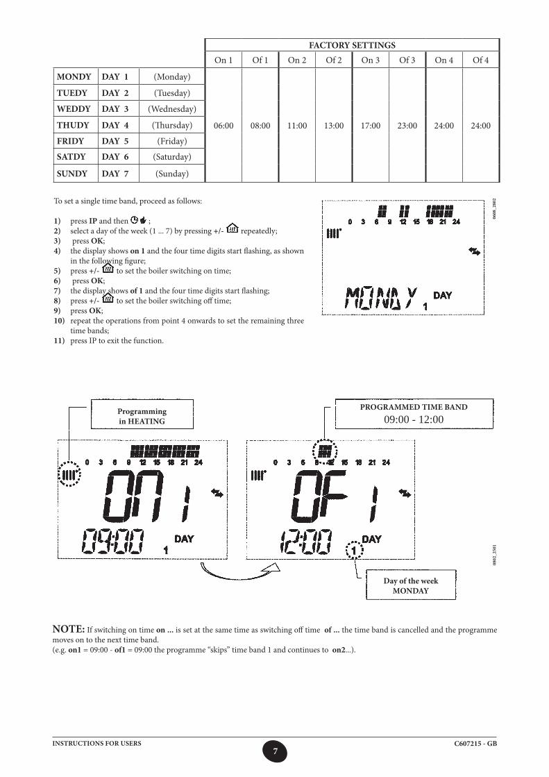
To set a single time band, proceed as follows:
1) press IP and then ;2) select a day of the week (1 ... 7) by pressing +/- repeatedly;3) press OK;4) the display shows on 1 and the four time digits start flashing, as shown
in the following figure;5) press +/- to set the boiler switching on time;6) press OK;7) the display shows of 1 and the four time digits start flashing;8) press +/- to set the boiler switching off time;9) press OK;10) repeat the operations from point 4 onwards to set the remaining three
time bands;11) press IP to exit the function.
0608
_280
2
FACTORY SETTINGSOn 1 Of 1 On 2 Of 2 On 3 Of 3 On 4 Of 4
MONDY DAY 1 (Monday)
06:00 08:00 11:00 13:00 17:00 23:00 24:00 24:00
TUEDY DAY 2 (Tuesday)
WEDDY DAY 3 (Wednesday)
THUDY DAY 4 (Thursday)
FRIDY DAY 5 (Friday)
SATDY DAY 6 (Saturday)
SUNDY DAY 7 (Sunday)
0802
_250
1
NOTE: If switching on time on ... is set at the same time as switching off time of ... the time band is cancelled and the programme moves on to the next time band.(e.g. on1 = 09:00 - of1 = 09:00 the programme “skips” time band 1 and continues to on2...).
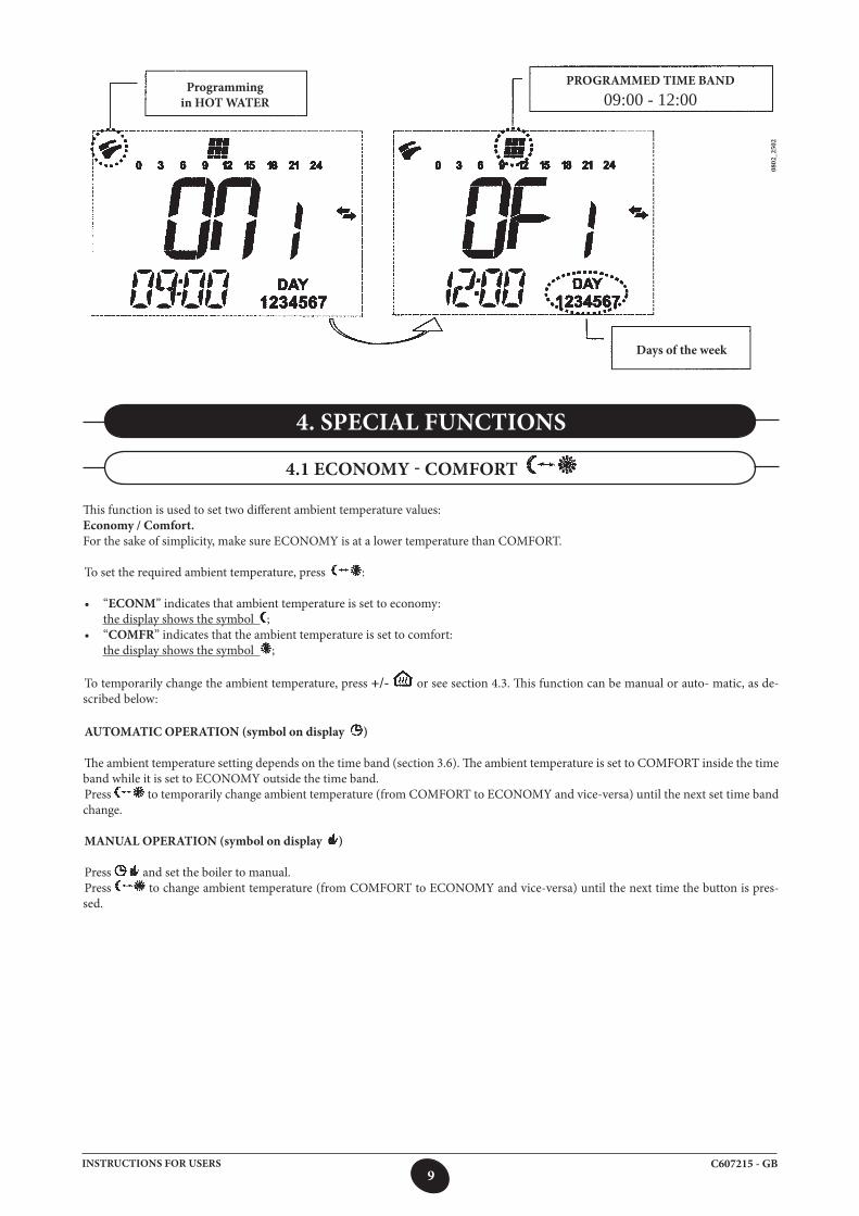
Programming in HEATING
PROGRAMMED TIME BAND 09:00 - 12:00
Day of the weekMONDAY
8C607215 - GBINSTRUCTIONS FOR USERS
Summary of available groups of days
FACTORY SETTINGS
“MO-FR” DAY 1 2 3 4 5 Monday to Friday As per table in section 3.6.1.
“SA-SU” DAY 6 7 Saturday and Sunday 07:00 – 23:00
“MO-SA” DAY 1 2 3 4 5 6 Monday to Saturday As per table in section 3.6.1.
“MO-SU” DAY 1 2 3 4 5 6 7 Every day in the week As per table in section 3.6.1.
3.6.2. Groups of days
This function allows you to programme 4 shared boiler switching on and switching cycles for several days or for the whole week (see summary below).
To set a single time band, proceed as follows:
1) Press IP and then ;2) a GROUP of days by pressing +/- ;3) Press OK;4) repeat the operations from points 4 to 10 of section 3.6.1.
3.7 HOURLY PROGRAMMING DOMESTIC HOT WATER MODE
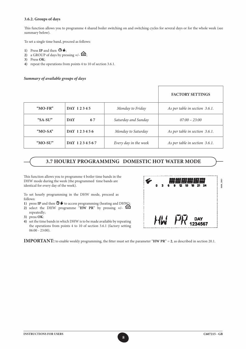
This function allows you to programme 4 boiler time bands in theDHW mode during the week (the programmed time bands areidentical for every day of the week).
To set hourly programming in the DHW mode, proceed asfollows:1) press IP and then to access programming (heating and DHW);2) select the DHW programme “HW PR” by pressing +/-
repeatedly;3) press OK:4) set the time bands in which DHW is to be made available by repeating
the operations from points 4 to 10 of section 3.6.1 (factory setting 06:00 - 23:00).
0608
_280
3
IMPORTANT: to enable weekly programming, the fitter must set the parameter “HW PR” = 2, as described in section 20.1.
9C607215 - GBINSTRUCTIONS FOR USERS
0802
_250
2
4. SPECIAL FUNCTIONS
4.1 ECONOMY - COMFORT
This function is used to set two different ambient temperature values:Economy / Comfort.For the sake of simplicity, make sure ECONOMY is at a lower temperature than COMFORT.
To set the required ambient temperature, press :
• “ECONM” indicates that ambient temperature is set to economy: the display shows the symbol ;• “COMFR” indicates that the ambient temperature is set to comfort: the display shows the symbol ;
To temporarily change the ambient temperature, press +/- or see section 4.3. This function can be manual or auto- matic, as de-scribed below:
AUTOMATIC OPERATION (symbol on display )
The ambient temperature setting depends on the time band (section 3.6). The ambient temperature is set to COMFORT inside the time band while it is set to ECONOMY outside the time band.Press to temporarily change ambient temperature (from COMFORT to ECONOMY and vice-versa) until the next set time band change.
MANUAL OPERATION (symbol on display )
Press and set the boiler to manual.Press to change ambient temperature (from COMFORT to ECONOMY and vice-versa) until the next time the button is pres-sed.
Programming in HOT WATER
PROGRAMMED TIME BAND 09:00 - 12:00
Days of the week
10C607215 - GBINSTRUCTIONS FOR USERS
The shower function optimises DHW control, for example, when someone is taking a shower.The function delivers DHW at a lower than rated temperature.To modify the maximum temperature of the shower function, proceed as described in section 4.3.
This function can be manually enabled as follows:• Pressoneofthetwobuttons+/- ( ) and then to enable the function SHOWR appears on the display for a few seconds followed by HW SS); • pressOK while the delivery temperature and the symbol flashes on the display;• thefunctionlasts60 minutes (the symbol flashes during this time. At the end of this period, DHW temperature returns to that of the operating mode set before the function activated (the symbol
not longer flashes on the display).
NOTE: to disable the function before the 60 minute period terminates, proceed as follows:
• pressoneofthetwobuttons+/- ( ) and then ;• pressOK the display visualises the message “HW S^”.
4.2 SHOWER FUNCTION
To change the temperature value, proceed as follows:
• PressIP to enable the PROG function;• press to scroll the functions to modify, as described in the following table:
Function Display Description of function
COMFRThe set temperature flashes(factory value = 20°C)
Boiler in heating mode at rated temperature.
ECONMThe set temperature flashes(factory value = 18°C)
Boiler in heating mode at reduced temperature
NOFRSThe set temperature flashes(factory value = 5°C)
Boiler in heating mode at preset antifreeze ambient temperature
SHOWRThe set temperature flashes(factory value = 40°C)
. Boiler in DHW mode at the preset temperature
• Tochangethevalueoftheselectedfunction,press+/- ;• Toexit,pressIP.
4.3 CHANGE TEMPERATURE VALUES OF THE FUNCTIONS ASSOCIATED WITH THE BUTTON
4.4.1 TIMED SHUTDOWN OFF (HOLIDAY PROGRAMME)
This function allows you to disable hourly programming (section 3.6) for a certain period of time. During this time, mini- mum ambient temperature is assured (factory setting 5°C). This setting may be modified as described in section 4.3 under “NOFRS”.To enable the function, proceed as follows:
• press and set the “AUTO” function (symbol );• press MM 60 appears on the display and the symbols flash.
4.4 TIMER FUNCTIONS (BUTTON )
11C607215 - GBINSTRUCTIONS FOR USERS
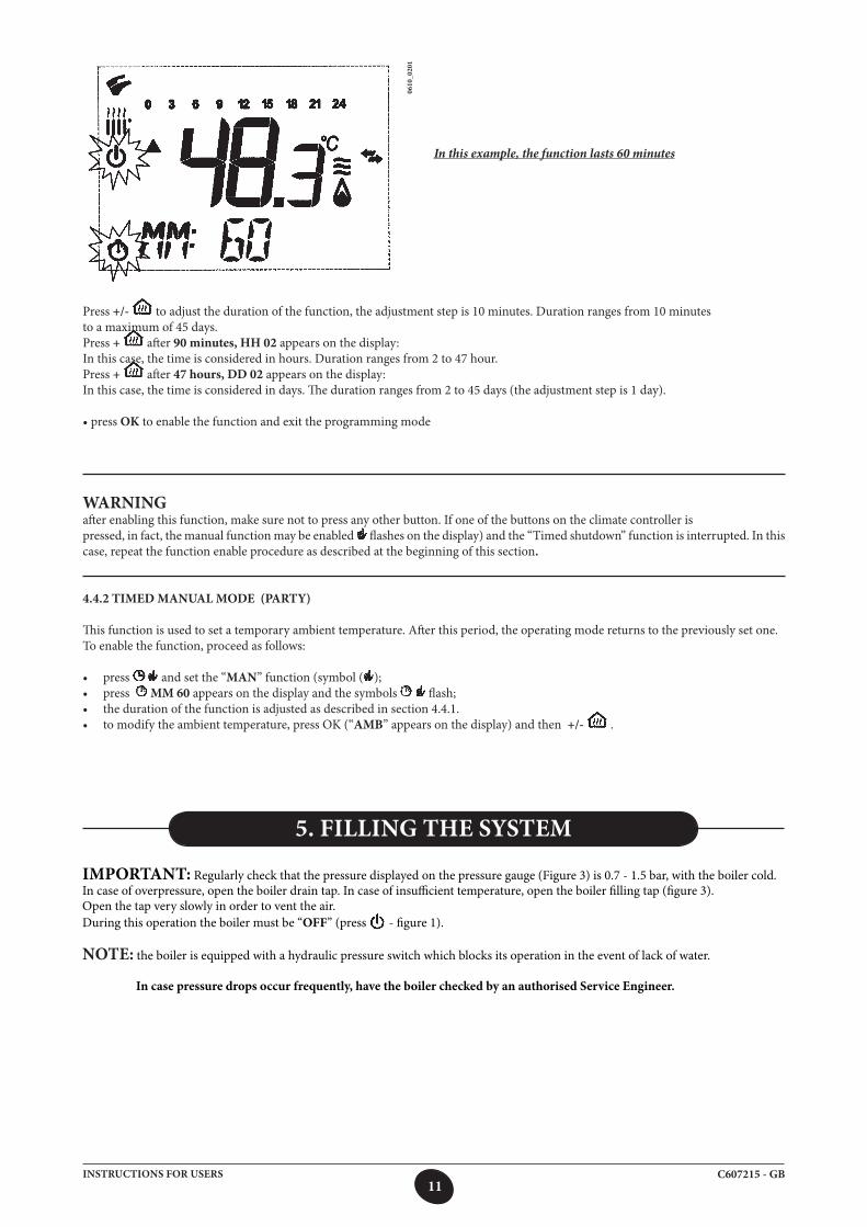
Press +/- to adjust the duration of the function, the adjustment step is 10 minutes. Duration ranges from 10 minutesto a maximum of 45 days. Press + after 90 minutes, HH 02 appears on the display:In this case, the time is considered in hours. Duration ranges from 2 to 47 hour.Press + after 47 hours, DD 02 appears on the display:In this case, the time is considered in days. The duration ranges from 2 to 45 days (the adjustment step is 1 day).
•pressOK to enable the function and exit the programming mode
WARNINGafter enabling this function, make sure not to press any other button. If one of the buttons on the climate controller ispressed, in fact, the manual function may be enabled flashes on the display) and the “Timed shutdown” function is interrupted. In this case, repeat the function enable procedure as described at the beginning of this section.
4.4.2 TIMED MANUAL MODE (PARTY)
This function is used to set a temporary ambient temperature. After this period, the operating mode returns to the previously set one.To enable the function, proceed as follows:
• press and set the “MAN” function (symbol ( );• press MM 60 appears on the display and the symbols flash;• thedurationofthefunctionisadjustedasdescribedinsection4.4.1.• tomodifytheambienttemperature,pressOK(“AMB” appears on the display) and then +/- .
0610
_020
1
In this example, the function lasts 60 minutes
IMPORTANT: Regularly check that the pressure displayed on the pressure gauge (Figure 3) is 0.7 - 1.5 bar, with the boiler cold. In case of overpressure, open the boiler drain tap. In case of insufficient temperature, open the boiler filling tap (figure 3).Open the tap very slowly in order to vent the air.During this operation the boiler must be “OFF” (press - figure 1).
NOTE: the boiler is equipped with a hydraulic pressure switch which blocks its operation in the event of lack of water.
In case pressure drops occur frequently, have the boiler checked by an authorised Service Engineer.
5. FILLING THE SYSTEM
12C607215 - GBINSTRUCTIONS FOR USERS
To switch off the boiler, disconnect the electric power supply. With the gas boiler in “OFF” mode (section 3.2), the electric circuits remain powered and the anti-freeze function is enabled (section 8).
6. TURNING OFF THE BOILER
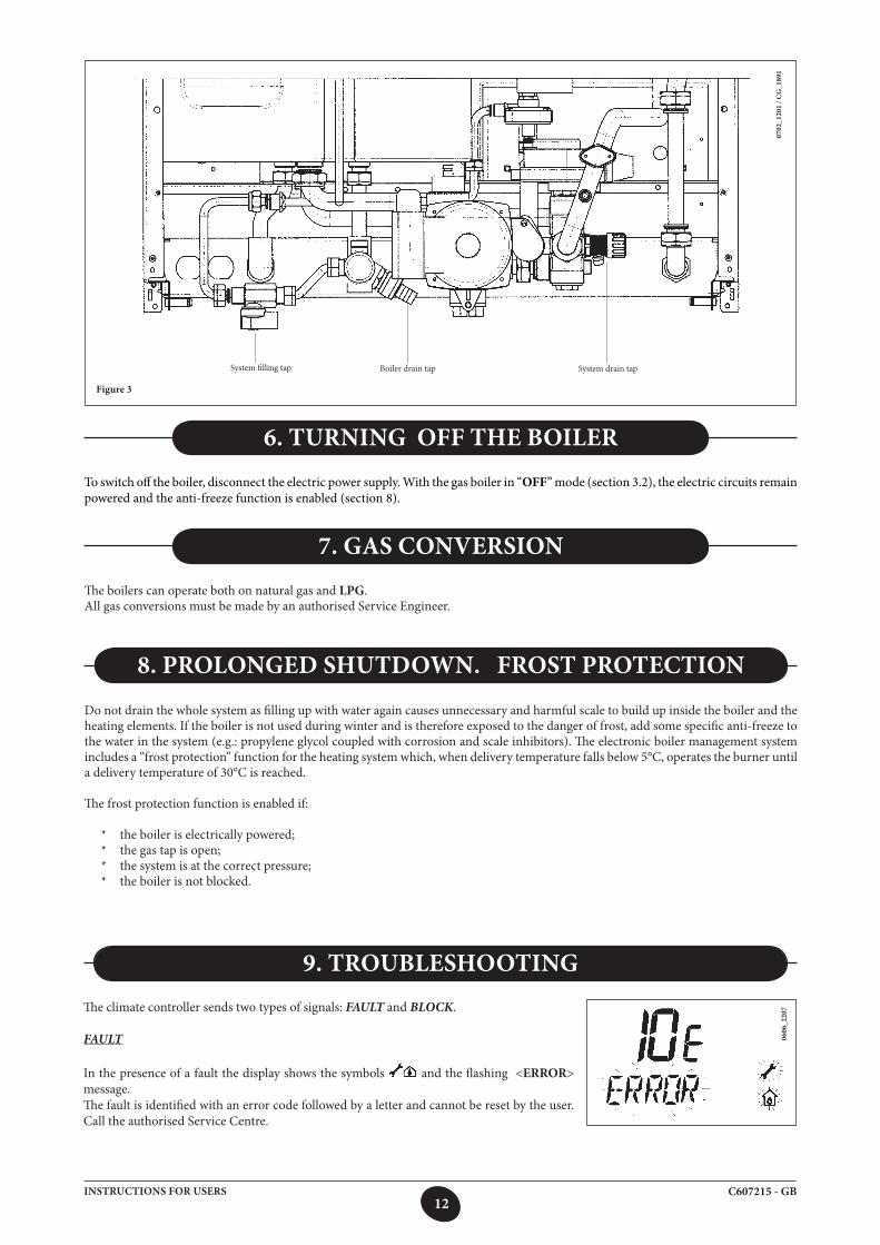
The climate controller sends two types of signals: FAULT and BLOCK.
FAULT
In the presence of a fault the display shows the symbols and the flashing <ERROR> message.The fault is identified with an error code followed by a letter and cannot be reset by the user. Call the authorised Service Centre.
0606
_220
7
9. TROUBLESHOOTING
7. GAS CONVERSIONThe boilers can operate both on natural gas and LPG.All gas conversions must be made by an authorised Service Engineer.
Do not drain the whole system as filling up with water again causes unnecessary and harmful scale to build up inside the boiler and the heating elements. If the boiler is not used during winter and is therefore exposed to the danger of frost, add some specific anti-freeze to the water in the system (e.g.: propylene glycol coupled with corrosion and scale inhibitors). The electronic boiler management system includes a “frost protection” function for the heating system which, when delivery temperature falls below 5°C, operates the burner until a delivery temperature of 30°C is reached.
The frost protection function is enabled if:
* the boiler is electrically powered; * the gas tap is open; * the system is at the correct pressure; * the boiler is not blocked.
8. PROLONGED SHUTDOWN. FROST PROTECTION
0702
_120
1 / C
G_1
891
System filling tap Boiler drain tap
Figure 3
System drain tap
13C607215 - GBINSTRUCTIONS FOR USERS
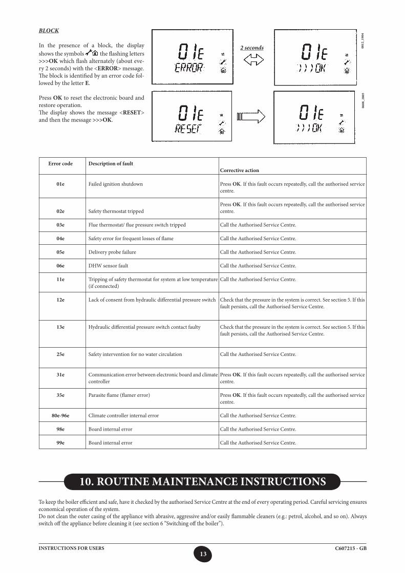
BLOCK
In the presence of a block, the display shows the symbols the flashing letters >>>OK which flash alternately (about eve-ry 2 seconds) with the <ERROR> message.The block is identified by an error code fol-lowed by the letter E.
Press OK to reset the electronic board and restore operation.The display shows the message <RESET> and then the message >>>OK.
0608
_280
508
12_1
904
To keep the boiler efficient and safe, have it checked by the authorised Service Centre at the end of every operating period. Careful servicing ensures economical operation of the system.Do not clean the outer casing of the appliance with abrasive, aggressive and/or easily flammable cleaners (e.g.: petrol, alcohol, and so on). Always switch off the appliance before cleaning it (see section 6 “Switching off the boiler”).
10. ROUTINE MAINTENANCE INSTRUCTIONS
Error code
01e
02e
03e
04e
05e
06e
11e
12e
13e
25e
31e
35e
80e-96e
98e
99e
Description of fault
Failed ignition shutdown
Safety thermostat tripped
Flue thermostat/ flue pressure switch tripped
Safety error for frequent losses of flame
Delivery probe failure
DHW sensor fault
Tripping of safety thermostat for system at low temperature (if connected)
Lack of consent from hydraulic differential pressure switch
Hydraulic differential pressure switch contact faulty
Safety intervention for no water circulation
Communication error between electronic board and climate controller
Parasite flame (flamer error)
Climate controller internal error
Board internal error
Board internal error
Corrective action
Press OK. If this fault occurs repeatedly, call the authorised service centre.
Press OK. If this fault occurs repeatedly, call the authorised service centre.
Call the Authorised Service Centre.
Call the Authorised Service Centre.
Call the Authorised Service Centre.
Call the Authorised Service Centre.
Call the Authorised Service Centre.
Check that the pressure in the system is correct. See section 5. If this fault persists, call the Authorised Service Centre.
Check that the pressure in the system is correct. See section 5. If this fault persists, call the Authorised Service Centre.
Call the Authorised Service Centre.
Press OK. If this fault occurs repeatedly, call the authorised service centre.
Press OK. If this fault occurs repeatedly, call the authorised service centre.
Call the Authorised Service Centre.
Call the Authorised Service Centre.
Call the Authorised Service Centre.
2 seconds
14C607215 - GBINSTRUCTIONS FOR FITTERS
This boiler has been designed to heat water to a temperature lower than boiling point at atmospheric pressure. It must be connected to a central heating system and to a domestic hot water supply system according to its performance and power output.Do the following before connecting the boiler:
a) Make sure that the boiler is adjusted to use the type of gas delivered by the gas supply. To do this, check the markings on the packaging and the rating plate on the appliance.
b) Make sure that the flue terminal draft is appropriate, that the terminal is not obstructed and that no exhaust gases from other appliances are expelled through the same flue duct, unless the latter has been specially designed to collect exhaust gas from more than one appliance, in compliance with current laws and regulations.
c) Make sure that, if the boiler is connected to existing flue ducts, these have been thoroughly cleaned as residual products of combustion may detach from the walls during operation and obstruct the flow of fumes.
To ensure correct operation and maintain the warranty, observe the following precautions:
1. DHW circuit:1.1. If the water is harder than 20 °F (1 °F = 10 mg calcium carbonate per litre of water), install a polyphosphate dispenser or an
equivalent treatment system, compliant with current regulations.1.2. Thoroughly flush the system after installation of the appliance and before use.
2. Heating circuit2.1. new system Before proceeding with installation of the boiler, the system must be cleaned and flushed to eliminate residual thread-cutting
swarf, solder and any solvents, using suitable proprietary products. To avoid damaging metal, plastic and rubber parts, only use neutral cleaners, i.e. non-acid and non alkaline. Recommended cleaning products are: SENTINEL X300 or X400 and FERNOX Regenerator for heating circuits. Use these products in strict compliance with the manufacturers’ instructions.
2.2. existing plant: Before installing the boiler, drain the system and clean it to remove sludge and contaminants, using suitable proprietary products
as described in section 2.1. To avoid damaging metal, plastic and rubber parts, use only neutral cleaners, i.e. non-acid and non-alkaline such as SENTINEL X100 and FERNOX Protector for heating circuits. Use these products in strict compliance with the manufacturers’ instructions. Remember that the presence of foreign bodies in the heating system can adversely affect boiler operation (e.g. overheating and excessive noise of the heat exchanger).
Failure to observe the above will render the guarantee null and void.
The following notes and instructions are addressed to fitters to allow them to carry out trouble-free installation. Instructions for lighting and using the boiler are contained in the ‘Instructions for Users’ section. Additionally, bear in mind the following:• Thisboilercanbeconnectedtoanytypeofdouble-orsingle-pipeconvectorplate,radiatororthermoconvector.Designthesystem
sections as usual, though, bearing in mind the available flow-head at the plate, as shown in section 26.• Donotleaveanypackaging(plasticbags,polystyrene,etc.)withinthereachofchildrenastheyareapotentialsourceofdanger.• InitiallightingoftheboilermustbecarriedoutbyanauthorisedServiceEngineer,asindicatedontheattachedsheet.Failure to observe the above will render the guarantee null and void.
11. GENERAL INFORMATION
12. INSTRUCTIONS PRIOR TO INSTALLATION
15C607215 - GBINSTRUCTIONS FOR FITTERS
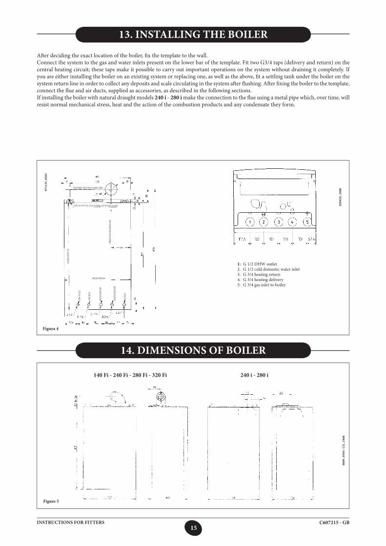
13. INSTALLING THE BOILER
After deciding the exact location of the boiler, fix the template to the wall.Connect the system to the gas and water inlets present on the lower bar of the template. Fit two G3/4 taps (delivery and return) on the central heating circuit; these taps make it possible to carry out important operations on the system without draining it completely. If you are either installing the boiler on an existing system or replacing one, as well as the above, fit a settling tank under the boiler on the system return line in order to collect any deposits and scale circulating in the system after flushing. After fixing the boiler to the template, connect the flue and air ducts, supplied as accessories, as described in the following sections.If installing the boiler with natural draught models 240 i - 280 i make the connection to the flue using a metal pipe which, over time, will resist normal mechanical stress, heat and the action of the combustion products and any condensate they form.
14. DIMENSIONS OF BOILER
9711
25_0
201
Figura 4
1: G 1/2 DHW outlet2: G 1/2 cold domestic water inlet3: G 3/4 heating return4: G 3/4 heating delivery5: G 3/4 gas inlet to boiler
0204
18_1
000DISCHARGE AXIS WITH COAXIAL CURVE
Drill with a Ø 12 bit, fit the rawlplugs and the hooks provided
BOILER WIDTH 60
DHW
INLE
T
DHW
OUTL
ET
HEAT
ING R
ETUR
N
HEAT
ING D
ELIVE
RY
GAS IN
LET
FORC
ED FL
OW DI
SCHA
RGE A
XIS
BOILE
R HEIG
HT 95
0
Figure 5
0609
_050
4 / C
G_1
848
140 Fi - 240 Fi - 280 Fi - 320 Fi 240 i - 280 i
16C607215 - GBINSTRUCTIONS FOR FITTERS
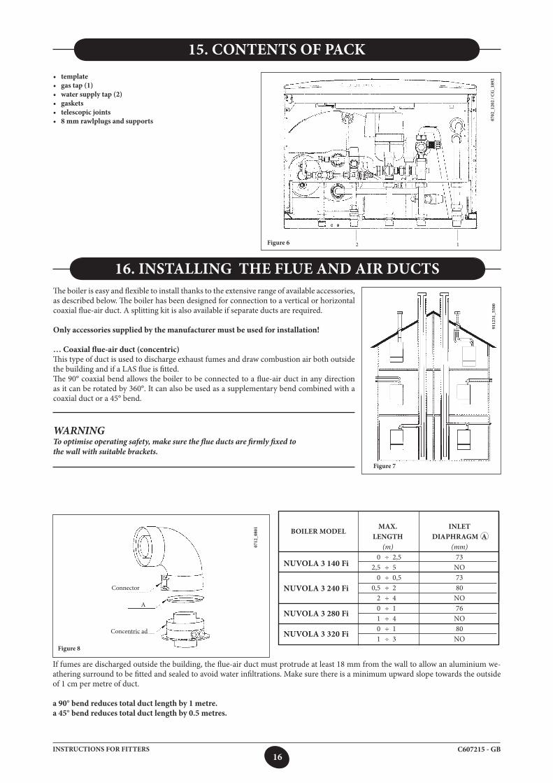
15. CONTENTS OF PACK • template• gas tap (1)• water supply tap (2)• gaskets• telescopic joints• 8 mm rawlplugs and supports
Figure 6
0702
_120
2 / C
G_1
892
16. INSTALLING THE FLUE AND AIR DUCTSThe boiler is easy and flexible to install thanks to the extensive range of available accessories, as described below. The boiler has been designed for connection to a vertical or horizontal coaxial flue-air duct. A splitting kit is also available if separate ducts are required.
Only accessories supplied by the manufacturer must be used for installation!
… Coaxial flue-air duct (concentric)This type of duct is used to discharge exhaust fumes and draw combustion air both outside the building and if a LAS flue is fitted.The 90° coaxial bend allows the boiler to be connected to a flue-air duct in any direction as it can be rotated by 360°. It can also be used as a supplementary bend combined with a coaxial duct or a 45° bend.
WARNINGTo optimise operating safety, make sure the flue ducts are firmly fixed tothe wall with suitable brackets.
9112
31_5
500
Figure 7
2 1
MAX. INLET LENGTH DIAPHRAGM A (m) (mm) 0 ÷ 2,5 73 2,5 ÷ 5 NO 0 ÷ 0,5 73 0,5 ÷ 2 80 2 ÷ 4 NO 0 ÷ 1 76 1 ÷ 4 NO 0 ÷ 1 80 1 ÷ 3 NO
NUVOLA 3 240 Fi
NUVOLA 3 280 Fi
Figure 8
BOILER MODEL
If fumes are discharged outside the building, the flue-air duct must protrude at least 18 mm from the wall to allow an aluminium we-athering surround to be fitted and sealed to avoid water infiltrations. Make sure there is a minimum upward slope towards the outside of 1 cm per metre of duct.
a 90° bend reduces total duct length by 1 metre. a 45° bend reduces total duct length by 0.5 metres.
0712
_080
1
Connector
Concentric ad
A
NUVOLA 3 320 Fi
NUVOLA 3 140 Fi
17C607215 - GBINSTRUCTIONS FOR FITTERS
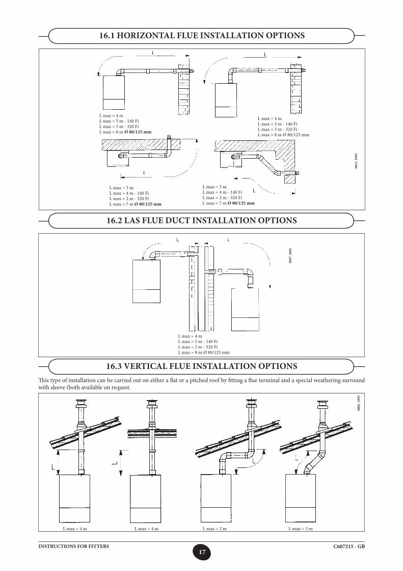
16.1 HORIZONTAL FLUE INSTALLATION OPTIONS
0612
_020
1
L max = 4 mL max = 5 m - 140 FiL max = 3 m - 320 Fi L max = 8 m Ø 80/125 mm
L max = 4 mL max = 5 m - 140 FiL max = 3 m - 320 FiL max = 8 m Ø 80/125 mm
L max = 3 mL max = 4 m - 140 FiL max = 2 m - 320 FiL max = 7 m Ø 80/125 mm
L max = 3 mL max = 4 m - 140 FiL max = 2 m - 320 FiL max = 7 m Ø 80/125 mm
16.2 LAS FLUE DUCT INSTALLATION OPTIONS
0607
_060
1
L max = 4 mL max = 5 m - 140 FiL max = 3 m - 320 FiL max = 8 m Ø 80/125 mm
16.3 VERTICAL FLUE INSTALLATION OPTIONSThis type of installation can be carried out on either a flat or a pitched roof by fitting a flue terminal and a special weathering surround with sleeve (both available on request.
0802
_250
3
L max = 4 m L max = 4 m L max = 2 m L max = 3 m
18C607215 - GBINSTRUCTIONS FOR FITTERS
For detailed installation instructions, consult the technical data provided with the accessories.
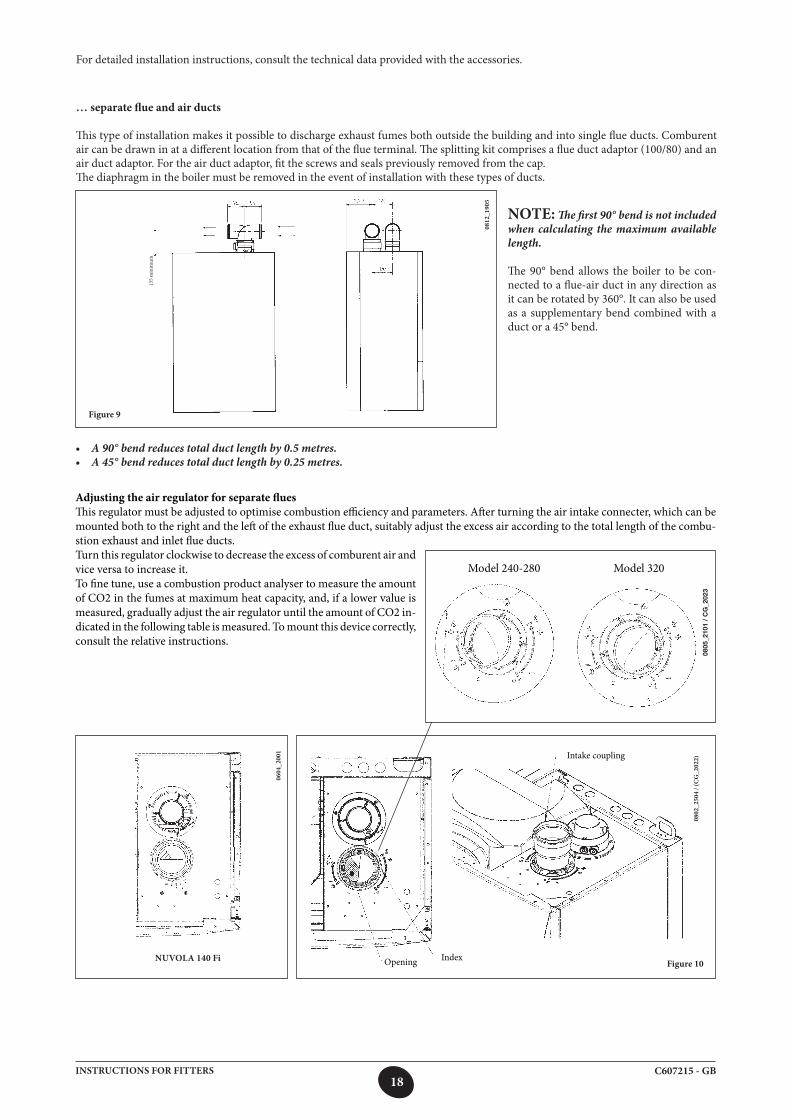
… separate flue and air ducts
This type of installation makes it possible to discharge exhaust fumes both outside the building and into single flue ducts. Comburent air can be drawn in at a different location from that of the flue terminal. The splitting kit comprises a flue duct adaptor (100/80) and an air duct adaptor. For the air duct adaptor, fit the screws and seals previously removed from the cap. The diaphragm in the boiler must be removed in the event of installation with these types of ducts.
• A 90° bend reduces total duct length by 0.5 metres. • A 45° bend reduces total duct length by 0.25 metres.
Figure 10
Adjusting the air regulator for separate fluesThis regulator must be adjusted to optimise combustion efficiency and parameters. After turning the air intake connecter, which can be mounted both to the right and the left of the exhaust flue duct, suitably adjust the excess air according to the total length of the combu-stion exhaust and inlet flue ducts.
0802
_250
4 / (
CG
_202
2)
0812
_190
5
0604
_200
1
NUVOLA 140 Fi
NOTE: The first 90° bend is not included when calculating the maximum available length.
The 90° bend allows the boiler to be con-nected to a flue-air duct in any direction as it can be rotated by 360°. It can also be used as a supplementary bend combined with a duct or a 45° bend.
Model 240-280 Model 320Turn this regulator clockwise to decrease the excess of comburent air and vice versa to increase it.To fine tune, use a combustion product analyser to measure the amount of CO2 in the fumes at maximum heat capacity, and, if a lower value is measured, gradually adjust the air regulator until the amount of CO2 in-dicated in the following table is measured. To mount this device correctly, consult the relative instructions.
IndexOpening
Intake coupling
Figure 9
0805
_210
1 /
CG
_202
3
135
min
imum
19C607215 - GBINSTRUCTIONS FOR FITTERS
MAX LENGTH POSITION OF CO2% AIR REGULATOR
L1+L2(m) AFR G20 G30 G31 0 ÷ 10 1 10 ÷ 20 2 20 ÷ 30 3 0 ÷ 20 1 20 ÷ 30 2 0 ÷ 20 1 20 ÷ 30 2 0 ÷ 10 3 10 ÷ 25 4
NUVOLA3 COMFORT 240 Fi 6,1 8,7 8,7
NUVOLA3 COMFORT 280 Fi 7,1 8,0 8,0
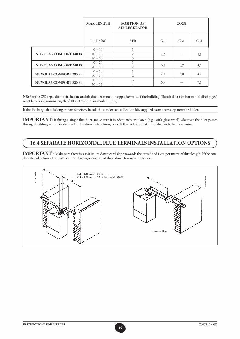
16.4 SEPARATE HORIZONTAL FLUE TERMINALS INSTALLATION OPTIONS
IMPORTANT - Make sure there is a minimum downward slope towards the outside of 1 cm per metre of duct length. If the con-densate collection kit is installed, the discharge duct must slope down towards the boiler.
(L1 + L2) max = 30 m(L1 + L2) max = 25 m for model 320 Fi
9112
31_4
805
L max = 10 m
9112
31_4
806
NB: For the C52 type, do not fit the flue and air duct terminals on opposite walls of the building. The air duct (for horizontal discharges) must have a maximum length of 10 metres (6m for model 140 Fi).
If the discharge duct is longer than 6 metres, install the condensate collection kit, supplied as an accessory, near the boiler.
IMPORTANT: if fitting a single flue duct, make sure it is adequately insulated (e.g.: with glass wool) wherever the duct passes through building walls. For detailed installation instructions, consult the technical data provided with the accessories.
NUVOLA3 COMFORT 140 Fi 4,0 — 4,3
NUVOLA3 COMFORT 320 Fi 6,7 — 7,6
20C607215 - GBINSTRUCTIONS FOR FITTERS
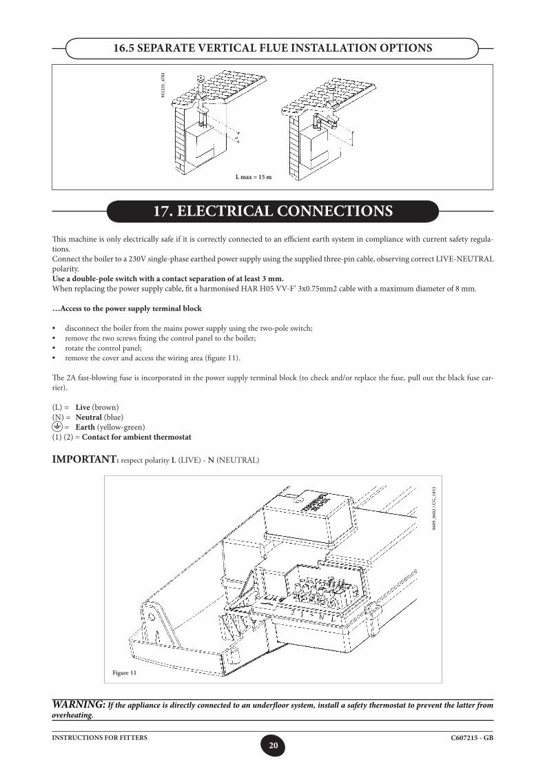
16.5 SEPARATE VERTICAL FLUE INSTALLATION OPTIONS
L max = 15 m
9112
31_4
701
17. ELECTRICAL CONNECTIONS
This machine is only electrically safe if it is correctly connected to an efficient earth system in compliance with current safety regula-tions.Connect the boiler to a 230V single-phase earthed power supply using the supplied three-pin cable, observing correct LIVE-NEUTRAL polarity. Use a double-pole switch with a contact separation of at least 3 mm. When replacing the power supply cable, fit a harmonised HAR H05 VV-F’ 3x0.75mm2 cable with a maximum diameter of 8 mm.
…Access to the power supply terminal block
• disconnect the boiler from the mains power supply using the two-pole switch;• remove the two screws fixing the control panel to the boiler; • rotate the control panel; • remove the cover and access the wiring area (figure 11).
The 2A fast-blowing fuse is incorporated in the power supply terminal block (to check and/or replace the fuse, pull out the black fuse car-rier).
(L) = Live (brown)(N) = Neutral (blue) = Earth (yellow-green)(1) (2) = Contact for ambient thermostat
IMPORTANT: respect polarity L (LIVE) - N (NEUTRAL)
Figure 11
0609
_060
2 /
CG
_185
3
WARNING: If the appliance is directly connected to an underfloor system, install a safety thermostat to prevent the latter from overheating.

21C607215 - GBINSTRUCTIONS FOR FITTERS
18. INSTALLING THE CLIMATE CONTROLLER
18.1 INSTALLING THE CLIMATE CONTROLLER ON THE FRONT PANEL OF THE BOILER
To install the climate controller inside the control strip of the front panel of the boiler, proceed as follows:
1. Remove the grille from the front panel of the boiler with your hands as shown in the figure below;2. Remove the cover from the template and then put it back on the front panel;3. Cut the two red wires and connect them as shown in figure C.4. Push the climate controller into the relative housing on the control strip of the front panel without applying excessive force;
0706_0501 / 56_8836
0606_0504
Figure A
Figure BFigure C
To connect the climate controller, proceed as follows:
• Priseopentheclimatecontroller(therearenoscrews)withyourhands;• ConnectthetwowiresfromtheM2terminalblockontheboiler(figure11),asillustratedinfigureC.
WARNINGthe climate controller is powered at LOW VOLTAGE. Do not connect it to the 230 V mains supply. For electrical connections, see sec-tions 28 and 31.
The climate controller can either be directly installed on the boiler or mounted on the wall.
0805_1601 / CG_1823
0805
_160
2 /
CG
_207
1
22C607215 - GBINSTRUCTIONS FOR FITTERS
CONNECTING THE AMBIENT THERMOSTAT
• accessthepowersupplyterminalblock(figure10);• connecttheambientthermostatterminalstoterminals(1)and(2);• powertheboiler;
Operation of key
The key is no longer operative as described in section 4.1 (ECONOMY-COMFORT function).The boiler supplies heat to the heating system only when the time band programmed by the user and the ambient thermostat are both requested.
By pressing the key it is possible to enable boiler operation when the ambient thermostat is requested but the programmed time band does not require heat (manual “forcing”). In this case the display of the climate controller shows the flashing symbol Manual operation ends at the next time band when heat is not requested in heating.
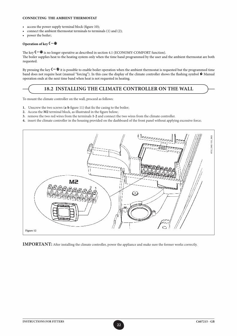
IMPORTANT: After installing the climate controller, power the appliance and make sure the former works correctly.
To mount the climate controller on the wall, proceed as follows:
1. Unscrew the two screws (a-b figure 11) that fix the casing to the boiler;2. Access the M2 terminal block, as illustrated in the figure below;3. remove the two red wires from the terminals 1-2 and connect the two wires from the climate controller.4. insert the climate controller in the housing provided on the dashboard of the front panel without applying excessive force;
18.2 INSTALLING THE CLIMATE CONTROLLER ON THE WALL
Figure 12
0712
_210
2 / C
G_2
021
23C607215 - GBINSTRUCTIONS FOR FITTERS
The authorised Technical Assistance Service can convert this boiler to natural gas (G. 20) or liquid gas (G.30, G. 31).
Carry out the following operations:
19. GAS CONVERSION
A) replace the main burner nozzles;B) change the modulator voltageC) new max. and min. calibration of the pressure regulator.
A) Replace the burner injectors• carefullypullthemainburneroffitsseat;• replace themainburner injectorsmakingsure to fully tighten
them to prevent gas leaks. Injector diameters are specified in table 2.
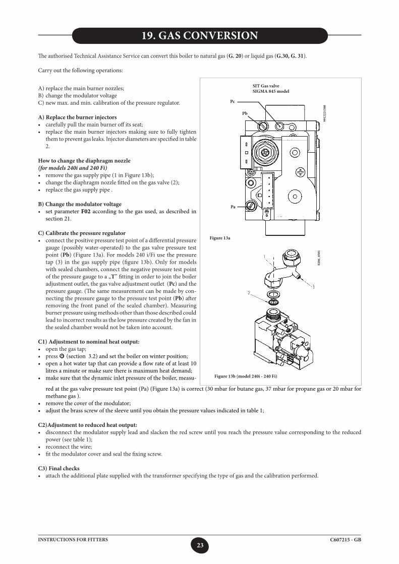
How to change the diaphragm nozzle (for models 240i and 240 Fi)• removethegassupplypipe(1inFigure13b);•changethediaphragmnozzlefittedonthegasvalve(2);• replacethegassupplypipe.
B) Change the modulator voltage• set parameter F02 according to the gas used, as described in
section 21.
C) Calibrate the pressure regulator• connectthepositivepressuretestpointofadifferentialpressure
gauge (possibly water-operated) to the gas valve pressure test point (Pb) (Figure 13a). For models 240 i/Fi use the pressure tap (3) in the gas supply pipe (figure 13b). Only for models with sealed chambers, connect the negative pressure test point of the pressure gauge to a „T” fitting in order to join the boiler adjustment outlet, the gas valve adjustment outlet (Pc) and the pressure gauge. (The same measurement can be made by con-necting the pressure gauge to the pressure test point (Pb) after removing the front panel of the sealed chamber). Measuring burner pressure using methods other than those described could lead to incorrect results as the low pressure created by the fan in the sealed chamber would not be taken into account.
C1) Adjustment to nominal heat output:• openthegastap;• press (section 3.2) and set the boiler on winter position;• openahotwatertapthatcanprovideaflowrateofatleast10
litres a minute or make sure there is maximum heat demand;• makesurethatthedynamicinletpressureoftheboiler,measu-
red at the gas valve pressure test point (Pa) (Figure 13a) is correct (30 mbar for butane gas, 37 mbar for propane gas or 20 mbar for methane gas ).
• removethecoverofthemodulator;• adjustthebrassscrewofthesleeveuntilyouobtainthepressurevaluesindicatedintable1;
C2)Adjustment to reduced heat output:• disconnectthemodulatorsupplyleadandslackentheredscrewuntilyoureachthepressurevaluecorrespondingtothereduced
power (see table 1);• reconnectthewire;• fitthemodulatorcoverandsealthefixingscrew.
C3) Final checks• attachtheadditionalplatesuppliedwiththetransformerspecifyingthetypeofgasandthecalibrationperformed.
SIT Gas valveSIGMA 845 model
Figure 13a
9912
2215
00
Pc
Pb
Pa
0206
_050
1
Figure 13b (model 240i - 240 Fi)
24C607215 - GBINSTRUCTIONS FOR FITTERS
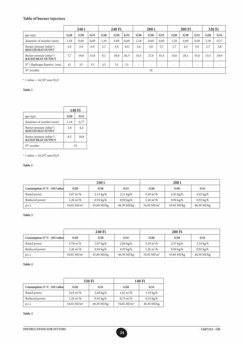
Table of burner injectors
240 i 240 Fi 280 i 280 Fi 320 Figas type G20 G30 G31 G20 G30 G31 G20 G30 G31 G20 G30 G31 G20 G31
diameter of nozzles (mm) 1,18 0,69 0,69 1,18 0,69 0,69 1,18 0,69 0,69 1,18 0,69 0,69 1,18 0,77
Burner pressure (mbar*) 1,6 3,9 6,9 1,7 3,9 6,9 1,6 3,8 5,7 1,7 4,3 5,9 1,7 3,8REDUCED HEAT OUTPUT
Burner pressure (mbar*) 7,7 19,8 25,6 8,1 20,6 26,3 10,3 27,6 35,4 10,6 28,1 35,6 13,5 29,9RATED HEAT OUTPUT
N° 1 diaphragm diameter (mm) 4,5 3,5 3,5 4,5 3,5 3,5 - - - - - - - -
N° nozzles 18
* 1 mbar = 10,197 mm H2O
Table 1
240 i 280 iConsumption 15 °C - 1013 mbar G20 G30 G31 G20 G30 G31
Rated power 2,87 m3/h 2,14 kg/h 2,11 kg/h 3,29 m3/h 2,45 kg/h 2,42 kg/h
Reduced power 1,26 m3/h 0,94 kg/h 0,92 kg/h 1,26 m3/h 0,94 kg/h 0,92 kg/h
p.c.i. 34,02 MJ/m3 45,60 MJ/kg 46,30 MJ/kg 34,02 MJ/m3 45,60 MJ/kg 46,30 MJ/kg
Table 2
140 Figas type G20 G31
diameter of nozzles (mm) 1,18 0,77
Burner pressure (mbar*) 1,8 4,2REDUCED HEAT OUTPUT
Burner pressure (mbar*) 8,5 18,8RATED HEAT OUTPUT
N° nozzles 10
* 1 mbar = 10,197 mm H2O
Table 1
240 Fi 280 FiConsumption 15 °C - 1013 mbar G20 G30 G31 G20 G30 G31
Rated power 2,78 m3/h 2,07 kg/h 2,04 kg/h 3,18 m3/h 2,37 kg/h 2,34 kg/h
Reduced power 1,26 m3/h 0,94 kg/h 0,92 kg/h 1,26 m3/h 0,94 kg/h 0,92 kg/h
p.c.i. 34,02 MJ/m3 45,60 MJ/kg 46,30 MJ/kg 34,02 MJ/m3 45,60 MJ/kg 46,30 MJ/kg
Table 2
320 Fi 140 FiConsumption 15 °C - 1013 mbar G20 G31 G20 G31
Rated power 3,65 m3/h 2,68 kg/h 1,62 m3/h 1,19 kg/h
Reduced power 1,26 m3/h 0,92 kg/h 0,73 m3/h 0,54 kg/h
p.c.i. 34,02 MJ/m3 46,30 MJ/kg 34,02 MJ/m3 46,30 MJ/kg
Table 2
25C607215 - GBINSTRUCTIONS FOR FITTERS
20. DISPLAY OF PARAMETERS
20.1 ADVANCED INFORMATION AND SETTINGS MODE
To enter the advanced information and settings mode, press IP and hold down for at least 3 seconds; access to the mode is confirmed by the moving “INFO” message.
To exit, simply press IP briefly.
To scroll the information, press OK; when the large figures start flashing, the value can be modified by pressing +/- .
WARNINGCommunication between the boiler electronic board and the climate controller is not immediate. In some casesit may be necessary to wait a certain time, depending on the type of information transmitted, before the command requested is carried out.
HEATING CIRCUIT
• “CH SL” Maximum temperature of heating circuit, set value with a +/- .
WARNINGpress to change the unit of measurement from °C to °F..
• “EXT°c” External temperature (with external probe connected).• “CH O>” Temperature of heating circuit delivery water.• “CH R<” Temperature of heating circuit return water (not contemplated).• “CH S^” Set-point of heating circuit water.• “CH MX” Maximum heating circuit setpoint (max. settable value).• “CH MN” Minimum heating circuit setpoint (min. settable value)
DHW CIRCUIT
• “HW O>” Temperature of DHW circuit or storage boiler delivery water.• “HW S^” Set-point of DHW circuit water. Value settable with the +/- keys.• “HW MX” Maximum DHW circuit water setpoint (max. settable value)• “HW MN” Minimum DHW circuit water setpoint (min. settable value)
ADVANCED INFORMATION
• “PWR %” Flame power level/modulation (in %).• “P BAR” Heating circuit water pressure (in bar). • “F L/M” Water flow leaving DHW circuit (in litres/min).
PARAMETER SETTINGS
• “K REG” Adjustment constant (0.5...9.0) of the temperature of the heating system delivery water (factory setting = 3 - See section 27 - Chart 3). Set value with +/- . A high value generates a higher delivery temperature in the heating system. By setting a correct K REG
adjustment constant, the ambient temperature remains at the set value regardless of the changes in external temperature.
• “BUILD” Adjustment parameter for the size of the building (1..10 - factory setting 5). Set value with +/- . An elevated value is associated with a building / heating system with elevated heat inertia, vice-versa, a low value is associated with small rooms or systems with low heat inertia (thermoconvectors).
• “YSELF” Enable/disable the self-adapting function of the heating delivery temperature (factory setting 1): The “K REG” constant undergoes a variation to reach ambient comfort. A value of 1 indicates that the function is enabled while a value of 0 indicates that it is disabled. This function is operative when connecting the external probe.
Press the keys +/- to change this value.
26C607215 - GBINSTRUCTIONS FOR FITTERS
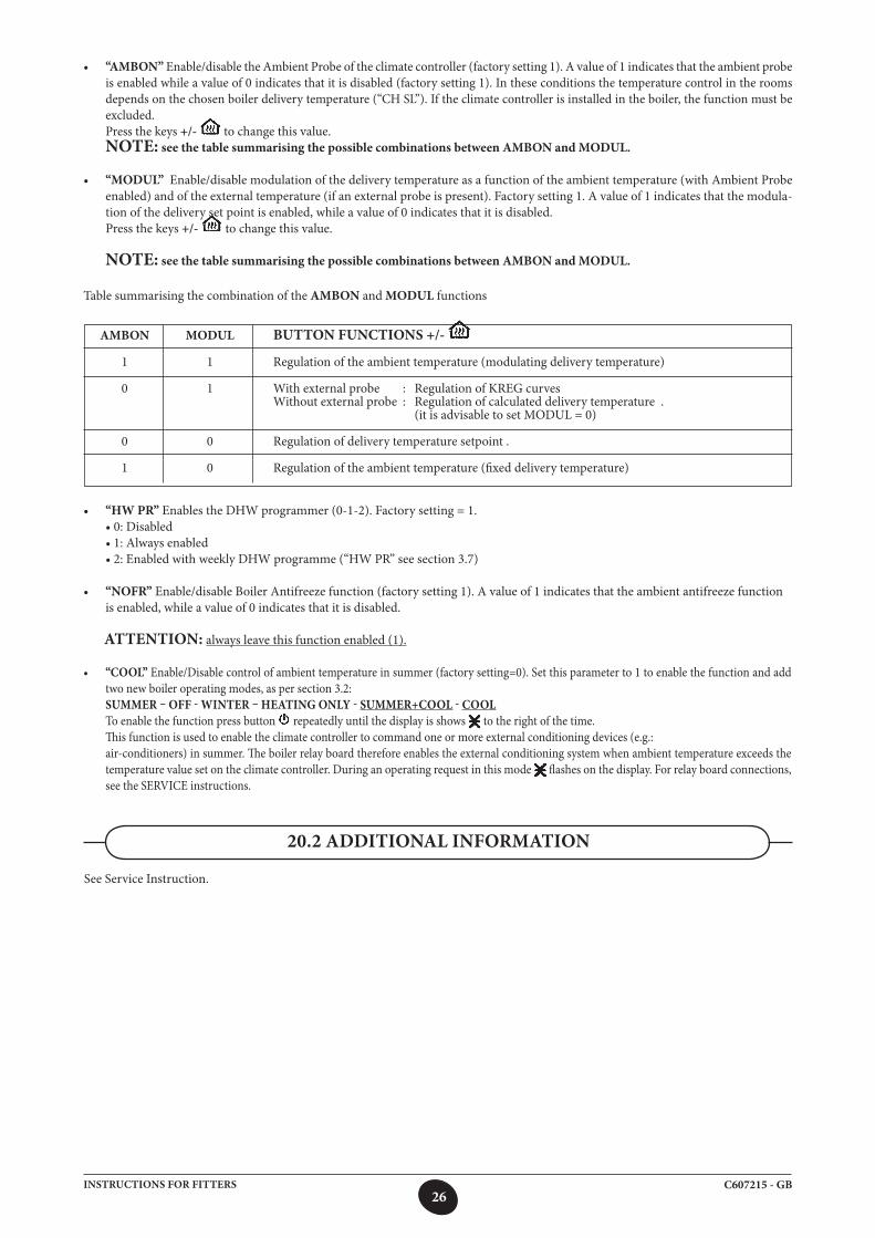
Table summarising the combination of the AMBON and MODUL functions
AMBON MODUL BUTTON FUNCTIONS +/- 1 1 Regulation of the ambient temperature (modulating delivery temperature)
0 1 Withexternalprobe : RegulationofKREGcurves Without external probe : Regulation of calculated delivery temperature . (it is advisable to set MODUL = 0)
0 0 Regulation of delivery temperature setpoint .
1 0 Regulation of the ambient temperature (fixed delivery temperature)
• “HW PR” Enables the DHW programmer (0-1-2). Factory setting = 1. •0:Disabled •1:Alwaysenabled •2:EnabledwithweeklyDHWprogramme(“HWPR”seesection3.7)
• “NOFR” Enable/disable Boiler Antifreeze function (factory setting 1). A value of 1 indicates that the ambient antifreeze function is enabled, while a value of 0 indicates that it is disabled.
ATTENTION: always leave this function enabled (1).
• “COOL” Enable/Disable control of ambient temperature in summer (factory setting=0). Set this parameter to 1 to enable the function and add two new boiler operating modes, as per section 3.2:
SUMMER – OFF - WINTER – HEATING ONLY - SUMMER+COOL - COOL To enable the function press button repeatedly until the display is shows to the right of the time. This function is used to enable the climate controller to command one or more external conditioning devices (e.g.: air-conditioners) in summer. The boiler relay board therefore enables the external conditioning system when ambient temperature exceeds the
temperature value set on the climate controller. During an operating request in this mode flashes on the display. For relay board connections, see the SERVICE instructions.
20.2 ADDITIONAL INFORMATION
See Service Instruction.
• “AMBON” Enable/disable the Ambient Probe of the climate controller (factory setting 1). A value of 1 indicates that the ambient probe is enabled while a value of 0 indicates that it is disabled (factory setting 1). In these conditions the temperature control in the rooms depends on the chosen boiler delivery temperature (“CH SL”). If the climate controller is installed in the boiler, the function must be excluded.
Press the keys +/- to change this value. NOTE: see the table summarising the possible combinations between AMBON and MODUL.
• “MODUL” Enable/disable modulation of the delivery temperature as a function of the ambient temperature (with Ambient Probe enabled) and of the external temperature (if an external probe is present). Factory setting 1. A value of 1 indicates that the modula-tion of the delivery set point is enabled, while a value of 0 indicates that it is disabled.
Press the keys +/- to change this value.
NOTE: see the table summarising the possible combinations between AMBON and MODUL.
27C607215 - GBINSTRUCTIONS FOR FITTERS
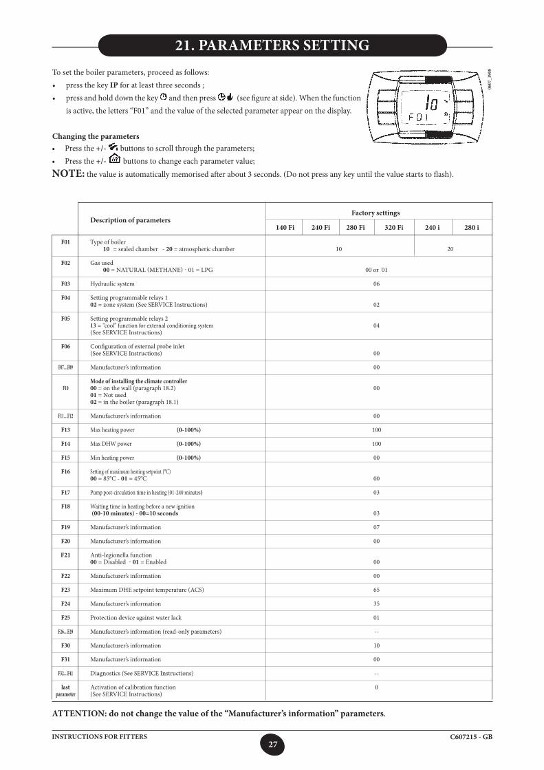
21. PARAMETERS SETTINGTo set the boiler parameters, proceed as follows:• pressthekeyIP for at least three seconds ;• pressandholddownthekey and then press (see figure at side). When the function
is active, the letters “F01” and the value of the selected parameter appear on the display.
Changing the parameters• Press the +/- buttons to scroll through the parameters;• Press the +/- buttons to change each parameter value;
NOTE: the value is automatically memorised after about 3 seconds. (Do not press any key until the value starts to flash).
0607
_190
8
Factory settings Description of parameters 140 Fi 240 Fi 280 Fi 320 Fi 240 i 280 i
F01 Type of boiler 10 = sealed chamber - 20 = atmospheric chamber 10 20
F02 Gas used 00 = NATURAL(METHANE)-01=LPG 00 or 01 F03 Hydraulic system 06
F04 Setting programmable relays 1 02 = zone system (See SERVICE Instructions) 02
F05 Setting programmable relays 2 13 = “cool” function for external conditioning system 04 (See SERVICE Instructions)
F06 Configuration of external probe inlet (See SERVICE Instructions) 00
F07…F09 Manufacturer’s information 00
Mode of installing the climate controller F10 00 = on the wall (paragraph 18.2) 00 01 = Not used 02 = in the boiler (paragraph 18.1)
F11…F12 Manufacturer’s information 00
F13 Max heating power (0-100%) 100
F14 Max DHW power (0-100%) 100
F15 Min heating power (0-100%) 00
F16 Setting of maximum heating setpoint (°C) 00 = 85°C - 01 = 45°C 00
F17 Pump post-circulation time in heating (01-240 minutes) 03
F18 Waiting time in heating before a new ignition (00-10 minutes) - 00=10 seconds 03
F19 Manufacturer’s information 07
F20 Manufacturer’s information 00 F21 Anti-legionella function 00 = Disabled -01 = Enabled 00 F22 Manufacturer’s information 00
F23 Maximum DHE setpoint temperature (ACS) 65 F24 Manufacturer’s information 35
F25 Protection device against water lack 01
F26…F29 Manufacturer’s information (read-only parameters) --
F30 Manufacturer’s information 10
F31 Manufacturer’s information 00
F32…F41 Diagnostics (See SERVICE Instructions) --
last Activation of calibration function 0 parameter (See SERVICE Instructions)
ATTENTION: do not change the value of the “Manufacturer’s information” parameters.
28C607215 - GBINSTRUCTIONS FOR FITTERS
This boiler has been designed in full compliance with European reference standards and, in particular, it is fitted with the following:
• Air pressure switch (model 140 Fi - 240 Fi - 280 Fi - 320 Fi) This device (17 - figure 20) only allows the burner to ignite if the exhaust flue duct is in perfect working order. In the event of one or more of the following faults: • flueterminalobstructed • venturitubesobstructed • fanblocked • venturitubeconnection-pressureswitchtripped The boiler remains on standby and error code E03 is displayed (see table in section 9).
• Fumes thermostat (model 240 i - 280 i) This device (15 - figure 21), the sensor of which is positioned to the left of the fumes hood, interrupts the flow of gas to the main burner if the flue is
obstructed and/or there is no draught. In these conditions the boiler shuts down and displays error code E03 (section 9). To restart immediately, after having removed the cause of intervention, see section 9.
It is forbidden to disable this safety device
• Safety thermostat Thanks to a sensor placed on the heating delivery line, the thermostat interrupts the flow of gas to the burner if the water in the primary circuit
overheats. In these conditions, the boiler is blocked and only after the fault has been eliminated can it be ignited again (See section 9).
It is forbidden to disable this safety device
• Flame ionisation detector The flame sensing electrode, located on the right-hand side of the burner, guarantees safety of operation in case of gas failure or incomplete ignition
of the burner. In these conditions, the boiler is blocked after 3 ignition attempts. To re-establish normal operating conditions, see section 9.
• Hydraulic pressure switch This device allows the main burner to be ignited only if system pressure is higher than 0.5 bars.
• Pump overrun for heating circuit The electronically-controlled pump post-circulation function lasts 3 minutes (F17 – section 21) and is enabled, in the heating mode, if the ambient
thermostat causes the burner to go out.
• Post-circulation of the DHW circuit pump The pump post-circulation, which is obtained electronically, has a duration of 30 seconds and is activated at the end of operation of the DHW
pump.
• Frost protection device (heating and DHW systems) The electronic boiler management system includes a “frost protection” function for the heating system which, when delivery temperature falls below
5°C, operates the burner until a delivery temperature of 30°C is reached.
• Lack of water circulation in the primary circuit (probably pump blocked or presence of air) If there is insufficient or no water circulating in the primary circuit, the boiler blocks and the error code 25E is shown on the display (section 9).
• Anti-block pump function If no heat demand is received for 24 consecutive hours, the pump will automatically start and operate for 10 seconds. This function is operative when the boiler is powered.
• Three-way valve anti-blockage function If no heat demand is received for a period of 24 hours, the three-way valve performs a complete switching cycle. This function is operative when the
boiler is powered.
• Hydraulic safety valve (heating circuit) This device is set to 3 bar and is used for the heating circuit.
Connect the safety valve to a drain tap. Do not use it to drain the heating circuit.
• Anti-legionellosis function The anti-legionellosis function is NOT active. To activate the function, set the parameter F21=01 (as described in section 21). When the function is active, at intervals of one week the boiler
electronic management brings the water contained inside the boiler to a temperature higher than 60°C (the function is operative only if the water has never exceeded 60°C in the previous 7 days).
NOTE: domestic hot water is guaranteed even if the NTC sensor (ref. 5 – figures 19-20) develops a fault. In this case, temperature is controlled by the delivery sensor.
22. ADJUSTMENT AND SAFETY DEVICES
29C607215 - GBINSTRUCTIONS FOR FITTERS
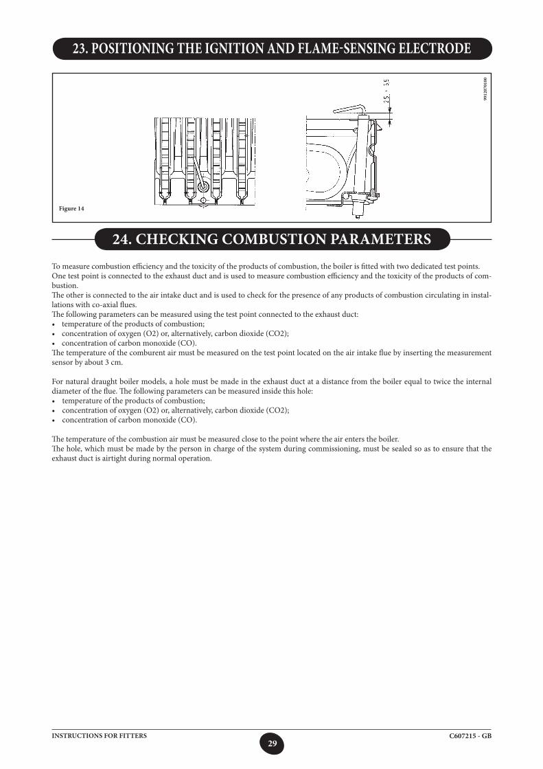
23. POSITIONING THE IGNITION AND FLAME-SENSING ELECTRODE
Figure 14
9912
0701
00
To measure combustion efficiency and the toxicity of the products of combustion, the boiler is fitted with two dedicated test points.One test point is connected to the exhaust duct and is used to measure combustion efficiency and the toxicity of the products of com-bustion.The other is connected to the air intake duct and is used to check for the presence of any products of combustion circulating in instal-lations with co-axial flues.The following parameters can be measured using the test point connected to the exhaust duct:• temperatureoftheproductsofcombustion;• concentrationofoxygen(O2)or,alternatively,carbondioxide(CO2);• concentrationofcarbonmonoxide(CO).The temperature of the comburent air must be measured on the test point located on the air intake flue by inserting the measurement sensor by about 3 cm.
For natural draught boiler models, a hole must be made in the exhaust duct at a distance from the boiler equal to twice the internal diameter of the flue. The following parameters can be measured inside this hole:• temperatureoftheproductsofcombustion;• concentrationofoxygen(O2)or,alternatively,carbondioxide(CO2);• concentrationofcarbonmonoxide(CO).
The temperature of the combustion air must be measured close to the point where the air enters the boiler.The hole, which must be made by the person in charge of the system during commissioning, must be sealed so as to ensure that the exhaust duct is airtight during normal operation.
24. CHECKING COMBUSTION PARAMETERS
30C607215 - GBINSTRUCTIONS FOR FITTERS
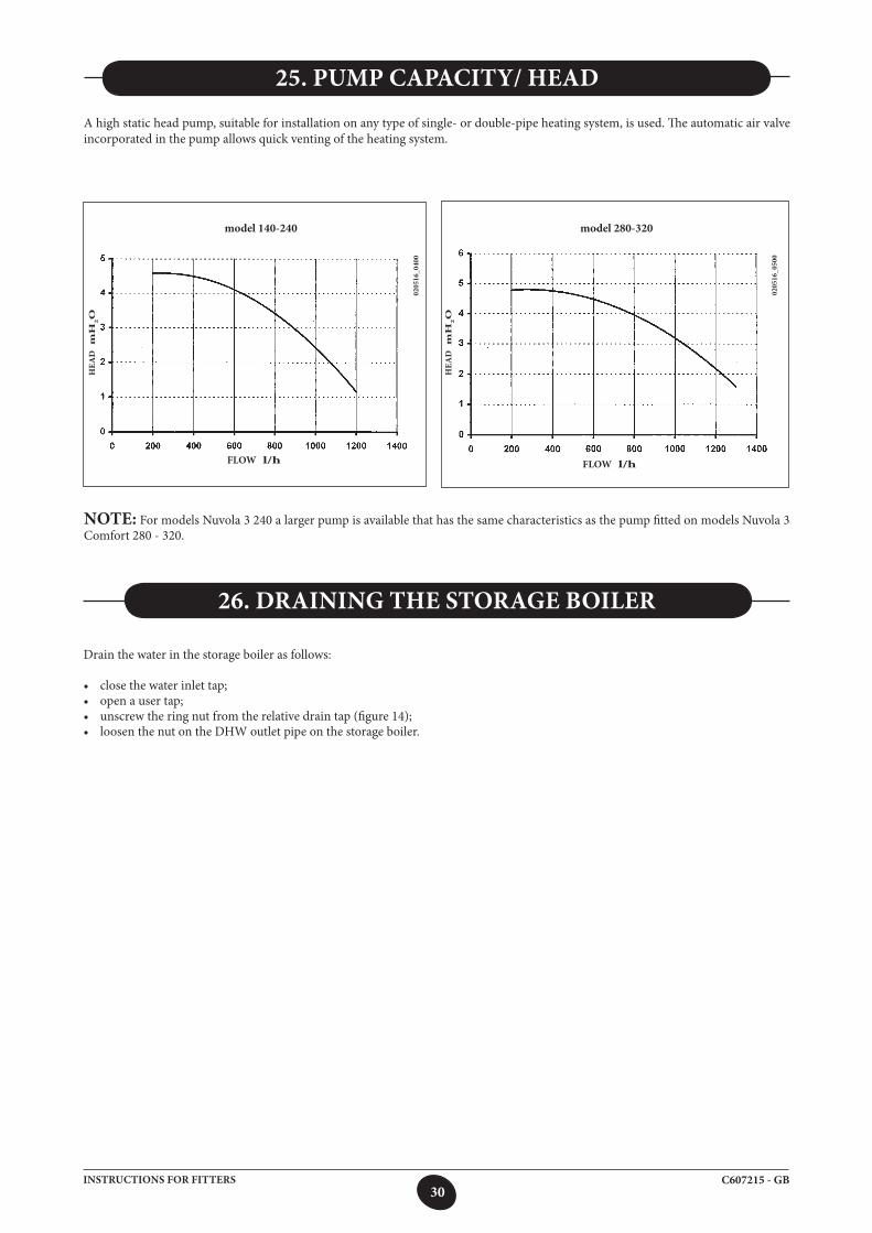
A high static head pump, suitable for installation on any type of single- or double-pipe heating system, is used. The automatic air valve incorporated in the pump allows quick venting of the heating system.
25. PUMP CAPACITY/ HEAD
model 280-320
0205
16_0
500
0205
16_0
400
model 140-240
NOTE: For models Nuvola 3 240 a larger pump is available that has the same characteristics as the pump fitted on models Nuvola 3 Comfort 280 - 320.
FLOW l/h
HEA
D m
H2O
FLOW l/h
HEA
D m
H2O
Drain the water in the storage boiler as follows:
• closethewaterinlettap;• openausertap;• unscrewtheringnutfromtherelativedraintap(figure14);• loosenthenutontheDHWoutletpipeonthestorageboiler.
26. DRAINING THE STORAGE BOILER
31C607215 - GBINSTRUCTIONS FOR FITTERS
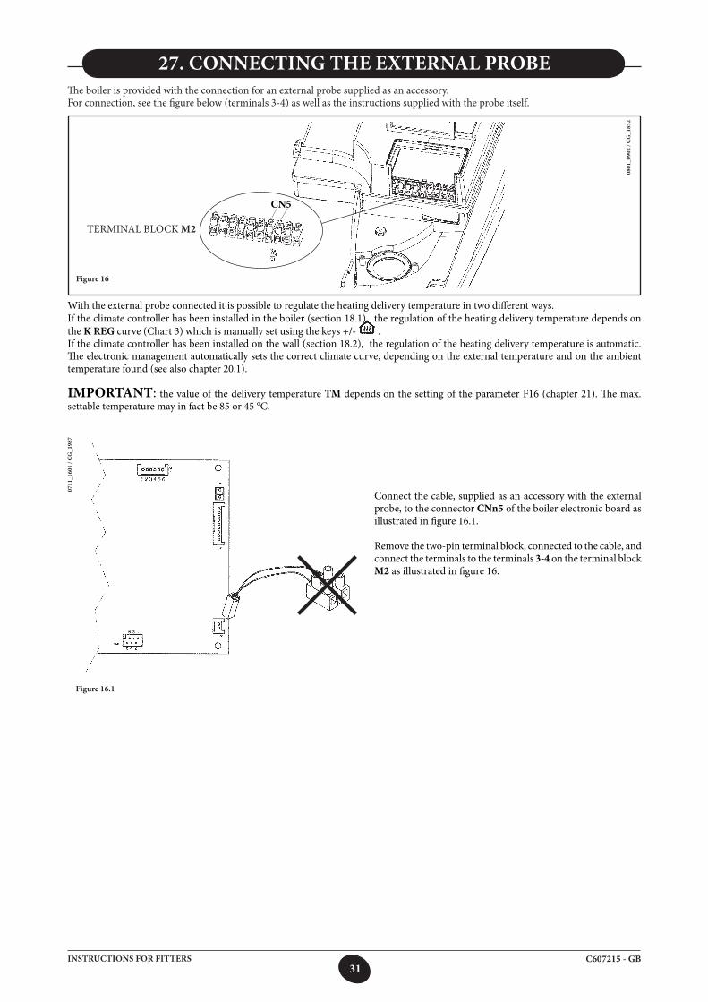
27. CONNECTING THE EXTERNAL PROBEThe boiler is provided with the connection for an external probe supplied as an accessory.For connection, see the figure below (terminals 3-4) as well as the instructions supplied with the probe itself.
Figure 16
0801
_090
2 / C
G_1
852
TERMINALBLOCK M2
With the external probe connected it is possible to regulate the heating delivery temperature in two different ways.If the climate controller has been installed in the boiler (section 18.1), the regulation of the heating delivery temperature depends on the K REG curve (Chart 3) which is manually set using the keys +/- .If the climate controller has been installed on the wall (section 18.2), the regulation of the heating delivery temperature is automatic. The electronic management automatically sets the correct climate curve, depending on the external temperature and on the ambient temperature found (see also chapter 20.1).
IMPORTANT: the value of the delivery temperature TM depends on the setting of the parameter F16 (chapter 21). The max. settable temperature may in fact be 85 or 45 °C.
CN5
0711
_160
1 / C
G_1
987
Connect the cable, supplied as an accessory with the external probe, to the connector CNn5 of the boiler electronic board as illustrated in figure 16.1.
Remove the two-pin terminal block, connected to the cable, and connect the terminals to the terminals 3-4 on the terminal block M2 as illustrated in figure 16.
Figure 16.1
32C607215 - GBINSTRUCTIONS FOR FITTERS
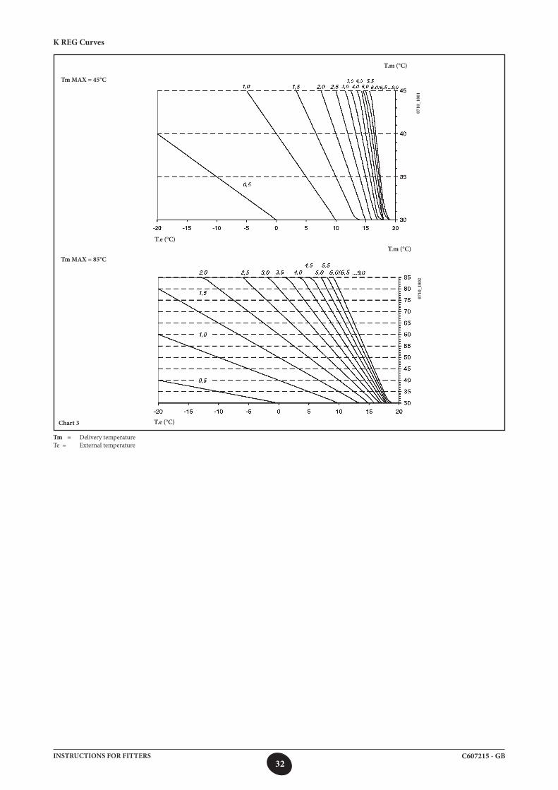
K REG Curves
Chart 3
Tm = Delivery temperatureTe = External temperature
0710
_180
107
10_1
802
T.e (°C)
T.m (°C)T.e (°C)
T.m (°C)
Tm MAX = 45°C
Tm MAX = 85°C
33C607215 - GBINSTRUCTIONS FOR FITTERS
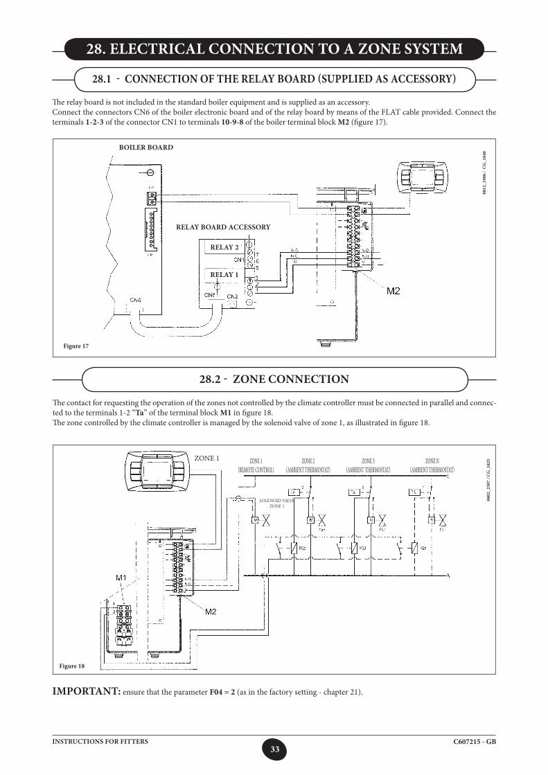
28. ELECTRICAL CONNECTION TO A ZONE SYSTEM
The contact for requesting the operation of the zones not controlled by the climate controller must be connected in parallel and connec-ted to the terminals 1-2 “Ta” of the terminal block M1 in figure 18.The zone controlled by the climate controller is managed by the solenoid valve of zone 1, as illustrated in figure 18.
IMPORTANT: ensure that the parameter F04 = 2 (as in the factory setting - chapter 21).
Figure 18
28.1 - CONNECTION OF THE RELAY bOARD (SUPPLIED AS ACCESSORY)
0812
_190
6 /
CG
_184
0
Figure 17
28.2 - ZONE CONNECTION
The relay board is not included in the standard boiler equipment and is supplied as an accessory.Connect the connectors CN6 of the boiler electronic board and of the relay board by means of the FLAT cable provided. Connect the terminals 1-2-3 of the connector CN1 to terminals 10-9-8 of the boiler terminal block M2 (figure 17).
0802
_250
7 / C
G_1
825
BOILER BOARD
RELAY bOARD ACCESSORY
ZONE 1 ZONE 1 (REMOTECONTROL)
ZONE 2 (AMBIENTTHERMOSTAT)
ZONE 3(AMBIENTTHERMOSTAT)
ZONE N (AMBIENTTHERMOSTAT)
SoLENoId VALVE ZoNE 1
RELAY 2
RELAY 1
34C607215 - GBINSTRUCTIONS FOR FITTERS
To optimise boiler efficiency, carry out the following annual controls:
• checktheappearanceandair-tightnessofthegasketsofthegasandcombustioncircuits;• checkthestateandcorrectpositionoftheignitionandflame-sensingelectrodes;• checkthestateoftheburnerandmakesureitisfirmlyfixed;• checkforanyimpuritiesinsidethecombustionchamber. Use a vacuum cleaner to do this;• checkthegasvalveiscorrectlycalibrated;• checkthepressureoftheheatingsystem;• checkthepressureoftheexpansionvessel;• checkthefanworkscorrectly;• makesuretheflueandairductsareunobstructed;• checkforanyimpuritiesinsidethesiphonfittedoncertainboilers;• checkthemagnesiumanode,wherepresent,forboilersfittedwithstorageboilers.
WARNINGSBefore commencing any maintenance operations, make sure the boiler is disconnected from the power supply.Afterwards, move the knobs and/or operating parameters of the boiler to their original positions.
29. ANNUAL SERVICING
35C607215 - GBINSTRUCTIONS FOR FITTERS
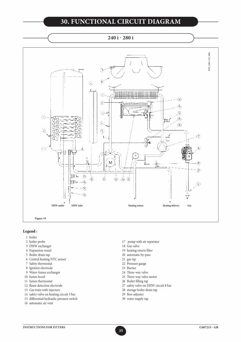
30. FUNCTIONAL CIRCUIT DIAGRAM
1 boiler 2 boiler probe 3 DHW exchanger 4 Expansion vessel 5 Boiler drain tap 6 Central heating NTC sensor 7 Safety thermostat 8 Ignition electrode 9 Water-fumes exchanger 10 fumes hood 11 fumes thermostat 12 flame detection electrode 13 Gas train with injectors 14 safety valve on heating circuit 3 bar 15 differential hydraulic pressure switch 16 automatic air vent
DHW outlet DHW inlet Heating return Heating delivery Gas
17 pump with air separator 18 Gas valve 19 heating return filter 20 automatic by-pass 21 gas tap 22 Pressure gauge 23 Burner 24 Three-way valve 25 Three-way valve motor 26 Boiler filling tap 27 safety valve on DHW circuit 8 bar 28 storage boiler drain tap 29 flow adjuster 30 water supply tap
240 i - 280 i
Figure 19
0702
_120
4 / C
G_1
884
Legend :
36C607215 - GBINSTRUCTIONS FOR FITTERS
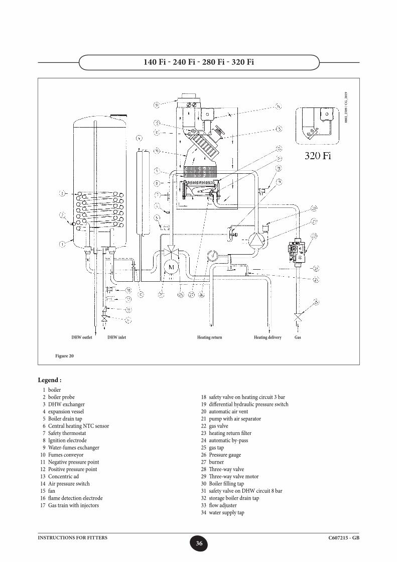
1 boiler 2 boiler probe 3 DHW exchanger 4 expansion vessel 5 Boiler drain tap 6 Central heating NTC sensor 7 Safety thermostat 8 Ignition electrode 9 Water-fumes exchanger 10 Fumes conveyor 11 Negative pressure point 12 Positive pressure point 13 Concentric ad 14 Air pressure switch 15 fan 16 flame detection electrode 17 Gas train with injectors
18 safety valve on heating circuit 3 bar 19 differential hydraulic pressure switch 20 automatic air vent 21 pump with air separator 22 gas valve 23 heating return filter 24 automatic by-pass 25 gas tap 26 Pressure gauge 27 burner 28 Three-way valve 29 Three-way valve motor 30 Boiler filling tap 31 safety valve on DHW circuit 8 bar 32 storage boiler drain tap 33 flow adjuster 34 water supply tap
140 Fi - 240 Fi - 280 Fi - 320 Fi
Legend :
Figure 20
0802
_250
9 / C
G_2
019
DHW outlet DHW inlet Heating return Heating delivery Gas
37C607215 - GBINSTRUCTIONS FOR FITTERS
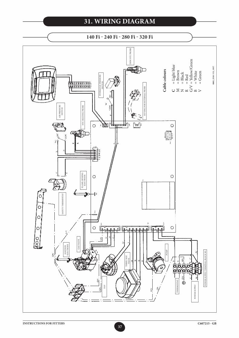
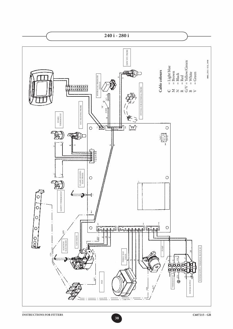
31. WIRING DIAGRAM
140 Fi - 240 Fi - 280 Fi - 320 Fi
Cab
le co
lour
s
C
= Li
ght b
lue
M
= Br
own
N
= Bl
ack
R
= Re
dG
/V =
Yel
low
/Gre
enB
=
Whi
teV
=
Gre
en
0802
_251
0 / C
G_1
937
FIT
TIN
G F
OR
EXTE
RNA
L PR
OBE
DH
W N
TC P
ROBE
NTC
HEA
TIN
G P
ROBE
AIR
PRE
SSU
RE
SWIT
CH
FLAME-SE
NSING
ELEC
TRO
DE
SAFE
TY
TH
ERM
OST
ATIG
NIT
ION
EL
ECTR
OD
E
GA
S VA
LVE
FAN
THRE
E-WAY
VA
LVE
PUM
P
THER
MO
STAT
POW
ER S
UPP
LY POWER
SUPP
LYTER
MIN
ALBL
OCKM
1
HY
DRA
ULI
C P
RESS
URE
SW
ITC
H
38C607215 - GBINSTRUCTIONS FOR FITTERS
240 i - 280 i
0802
_251
1 / (
CG
_193
8
Cab
le co
lour
s
C
= Li
ght b
lue
M
= Br
own
N
= Bl
ack
R
= Re
dG
/V =
Yel
low
/Gre
enB
=
Whi
teV
=
Gre
en
FIT
TIN
G F
OR
EXTE
RNA
L PR
OBE
DH
W N
TC P
ROBE
NTC
HEA
TIN
G P
ROBE
FUM
ES
THER
MO
STAT
FLAME-SE
NSING
ELEC
TRO
DE
SAFE
TY
TH
ERM
OST
ATIG
NIT
ION
EL
ECTR
OD
E
GA
S VA
LVE
FAN
THRE
E-WAY
VA
LVE
PUM
P
THER
MO
STAT
POW
ER S
UPP
LY POWER
SUPP
LYTER
MIN
ALBL
OCKM
1
HY
DRA
ULI
C P
RESS
URE
SW
ITC
H
39C607215 - GBINSTRUCTIONS FOR FITTERS
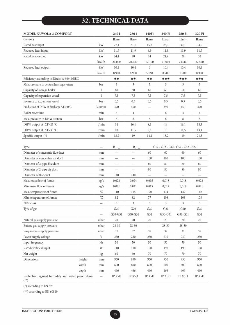
32. TECHNICAL DATA
MODEL NUVOLA 3 COMFORT 240 i 280 i 140Fi 240 Fi 280 Fi 320 FiCategory II2H3+ II2H3+ II2H3P II2H3+ II2H3+ II2H3P
Rated heat input kW 27,1 31,1 15,3 26,3 30,1 34,5
Reduced heat input kW 11,9 11,9 6,9 11,9 11,9 11,9
Rated heat output kW 24,4 28 14 24,4 28 32
kcal/h 21.000 24.080 12.100 21.000 24.080 27.520
Reduced heat output kW 10,4 10,4 6 10,4 10,4 10,4
kcal/h 8.900 8.900 5.160 8.900 8.900 8.900
Efficiency according to Directive 92/42/EEC – HH HH HH HHH HHH HHH
Max. pressure in central heating system bar 3 3 3 3 3 3
Capacity of storage boiler l 60 60 60 60 60 60
Capacity of expansion vessel l 7,5 7,5 7,5 7,5 7,5 7,5
Pressure of expansion vessel bar 0,5 0,5 0,5 0,5 0,5 0,5
Production of DHW at discharge ∆T=30°C l/30min 390 450 — 390 450 490
Boiler reset time min 6 4 — 6 4 4
Max. pressure in DHW system bar 8 8 8 8 8 8
DHW output at ∆T=25 °C l/min 14 16,1 8,1 14 16,1 18,3
DHW output at ∆T=35 °C l/min 10 11,5 5,8 10 11,5 13,1
Specific output (*) l/min 18,2 19 14,1 18,2 19 21,5
Type — B11BS B11BS C12 - C32 - C42 - C52 - C82 - B22
Diameter of concentric flue duct mm — — 60 60 60 60
Diameter of concentric air duct mm — — 100 100 100 100
Diameter of 2-pipe flue duct mm — — 80 80 80 80
Diameter of 2-pipe air duct mm — — 80 80 80 80
Diameter of flue duct mm 140 140 — — — —
Max. mass flow of fumes kg/s 0,022 0,024 0,015 0,018 0,018 0,022
Min. mass flow of fumes kg/s 0,021 0,021 0,015 0,017 0,018 0,021
Max. temperature of fumes °C 110 115 120 134 142 142
Min. temperature of fumes °C 82 82 77 108 108 108
NOx class — 3 3 3 3 3 3
Type of gas — G20 G20 G20 G20 G20 G20
— G30-G31 G30-G31 G31 G30-G31 G30-G31 G31
Natural gas supply pressure mbar 20 20 20 20 20 20
Butane gas supply pressure mbar 28-30 28-30 — 28-30 28-30 —
Propane gas supply pressure mbar 37 37 37 37 37 37
Power supply voltage V 230 230 230 230 230 230
Input frequency Hz 50 50 50 50 50 50
Rated electrical input W 110 110 190 190 190 190
Net weight kg 60 60 70 70 70 70
Dimensions height mm 950 950 950 950 950 950
width mm 600 600 600 600 600 600
depth mm 466 466 466 466 466 466
Protection against humidity and water penetration (**)
— IP X5D IP X5D IP X5D IP X5D IP X5D IP X5D
(*) according to EN 625
(**) according to EN 60529

A BAXI s.p.a., termékeit folyamatosan fejleszti, és fenntartja a jogot arra, hogy a jelen dokumentációban megadott adatokat bármikor előzetes értesítés nélkül módosítsa. a jelen dokumentáció információs jellegű, és nem tekinthető harmadik féllel szembeni szerződésnek.
C607215Ediz. 1 - 12/08