Embed Size (px)
Citation preview
Baxi 100 HEWall Mounted Powered Flue Condensing Boiler
Gas Fired Central Heating Unit
Installation and Servicing Instructions
Please leave these instructions with the user
2
Baxi UK Limited is one of the leading manufacturers
of domestic heating products in the UK.
Our first priority is to give a high quality service to our
customers. Quality is designed into every Baxi product
- products which fulfil the demands and needs of
customers, offering choice, efficiency and reliability.
To keep ahead of changing trends, we have made a
commitment to develop new ideas using the
latest technology - with the aim of continuing to make
the products that customers want to buy.
Everyone who works at Baxi has a commitment to
quality because we know that satisfied customers
mean continued success.
We hope you get a satisfactory service from Baxi. If
not, please let us know.
Natural Gas
Baxi 100 HEG.C.No 41 075 32
Baxi is a BS-EN ISO 9001 Accredited Company
The boiler meets the requirements of Statutory Instrument“ The Boiler (Efficiency) Regulations 1993 No 3083” and isdeemed to meet the requirements of Directive 92/42/EECon the energy efficiency requirements for new hot waterboilers fired with liquid or gaseous fuels:-
Type test for purpose of Regulation 5 certified by: Notified Body 0086.
Product/Production certified by:Notified Body 0086.
For GB/IE only.
3
1.0 Introduction 4
2.0 General Layout 5
3.0 Appliance Operation 6
4.0 Technical Data 7
5.0 Dimensions and Fixings 8
6.0 System Details 9
7.0 Site Requirements 12
8.0 Installation 17
9.0 Electrical 23
10.0 Commissioning the Boiler 25
11.0 Fitting the Outer Case 26
12.0 Servicing the Boiler 27
13.0 Changing Components 29
14.0 Fault Finding 36
15.0 Short Parts List 44
Section Page
Contents

Baxi UK Limited declare that no substancesharmful to health are contained in the applianceor used during appliance manufacture.
NOTE: This appliance must be installed inaccordance with the manufacturer’s instructionsand the regulations in force, and only used in asuitably ventilated location.
All systems must be thoroughly flushed andtreated with inhibitor (see Section 6.2).
Read the instructions fully before installing orusing the appliance.
1.1 Description
1. The Baxi 100 HE is a gas fired room sealed fanassisted condensing central heating boiler.
2. The maximum output of the boiler is preset at75,000 Btu/hr. The boiler will automatically adjustdown to 30,000 Btu/hr according to the systemload. If required, the output can be set to 100,000Btu/hr. Please refer to section 8.8.
3. It is designed for use on Natural Gas (G20).
4. The boiler is suitable for fully pumped openvented central heating and domestic hot watersystems and sealed systems.
5. A label giving details of the model, serial numberand Gas Council number is situated on the rear ofthe lower door panel (Fig. 1).
6. The boiler data badge is positioned on the airbox door (Fig. 2).
7. The boiler is intended to be installed inresidential / commercial / light industrial E.M.C.environments on a governed meter supply only.
8. The boiler must be installed with one of thepurpose designed flues such as the standardhorizontal flue kit, part no 236921.
1.2 Important Information
This product contains Refractory Ceramic Fibres(R.C.F.) which are man-made vitreous silicate fibres.Excessive exposure to these materials may causetemporary irritation to eyes, skin and respiratory tract.Care must be taken when handling these articles toensure the release of dust or fibres is kept to aminimum.To ensure that the release of fibres from these articlesis kept to a minimum, during installation and servicingit is recommended that a H.E.P.A. filtered vacuum isused to remove any dust, soot or other debrisaccumulated in and around the appliance. This shouldbe performed before and after working on theinstallation.It is recommended that any replaced item(s) are notbroken up but sealed within heavy duty polythenebags and clearly labelled “R.C.F. waste”. This is notclassified as “hazardous waste” and may be disposedof at a tipping site licensed for the disposal ofindustrial waste.Protective clothing is not required when handlingthese articles but it is recommended that gloves areworn and the normal hygiene rules of not smoking,eating or drinking in the work area are followed andalways wash hands before eating or drinking.
1.0 Introduction
4
Fig. 1
HIGH
LOW
HIGH
LOW
Data Badge
Air Box Door
Lower Door Panel
Position of Label
Fig. 2
“Benchmark” Log Book
As part of the industry-wide “Benchmark” initiative all Baxi boilers nowinclude an Installation, Commissioning and Service Record Log Book.Please read the Log Book carefully and complete all sections relevant tothe appliance and installation. These include sections on the type ofcontrols employed, flushing the system, burner operating pressure etc.The details of the Log Book will be required in the event of any warrantywork. Also, there is a section to be completed at each subsequent regularsevice visit.
2.0 General Layout
5
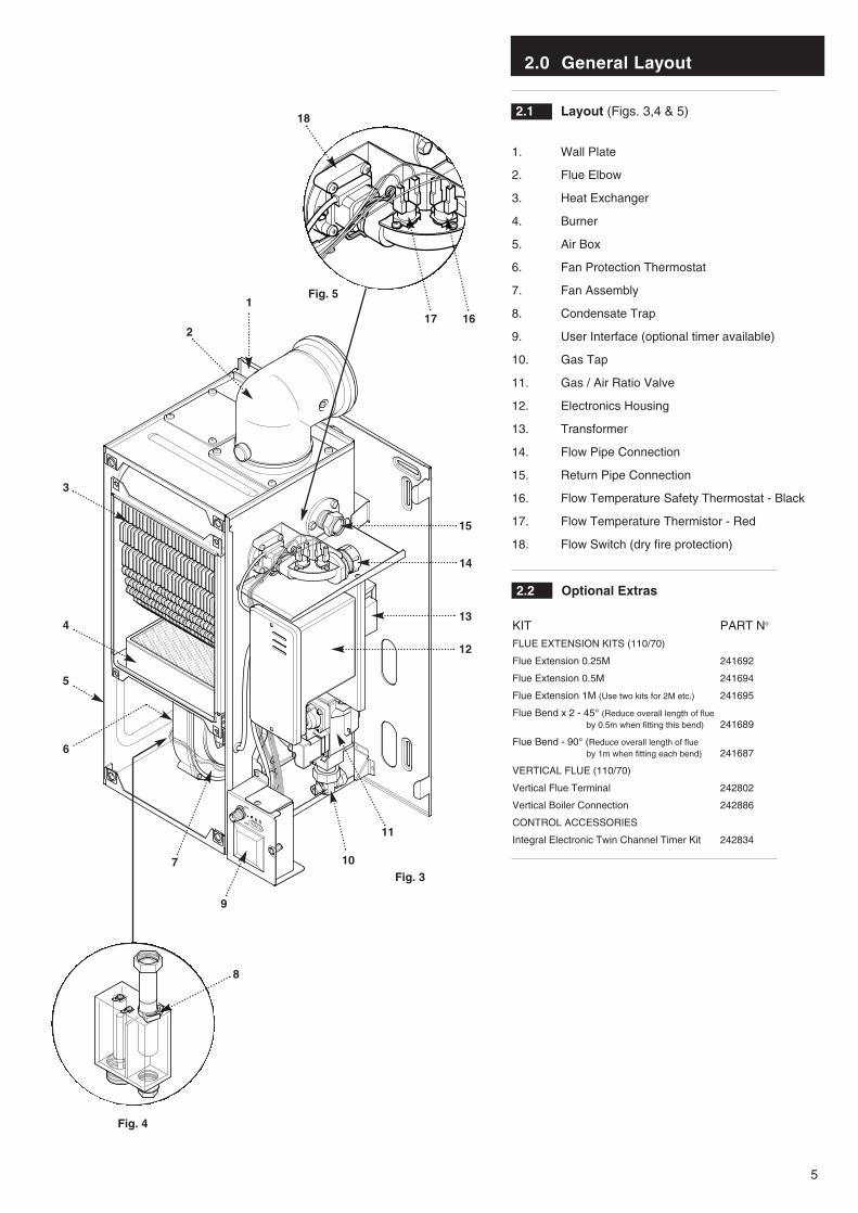
2.1 Layout (Figs. 3,4 & 5)
1. Wall Plate
2. Flue Elbow
3. Heat Exchanger
4. Burner
5. Air Box
6. Fan Protection Thermostat
7. Fan Assembly
8. Condensate Trap
9. User Interface (optional timer available)
10. Gas Tap
11. Gas / Air Ratio Valve
12. Electronics Housing
13. Transformer
14. Flow Pipe Connection
15. Return Pipe Connection
16. Flow Temperature Safety Thermostat - Black
17. Flow Temperature Thermistor - Red
18. Flow Switch (dry fire protection)
HIGH
LOW
1
2
3
4
5
6
7
9
8
10
11
12
13
17 16
14
15
18
Fig. 4
Fig. 3
Fig. 5
2.2 Optional Extras
KIT PART No
FLUE EXTENSION KITS (110/70)
Flue Extension 0.25M 241692
Flue Extension 0.5M 241694
Flue Extension 1M (Use two kits for 2M etc.) 241695
Flue Bend x 2 - 45° (Reduce overall length of flueby 0.5m when fitting this bend) 241689
Flue Bend - 90° (Reduce overall length of flueby 1m when fitting each bend) 241687
VERTICAL FLUE (110/70)
Vertical Flue Terminal 242802
Vertical Boiler Connection 242886
CONTROL ACCESSORIES
Integral Electronic Twin Channel Timer Kit 242834
3.0 Appliance Operation
6
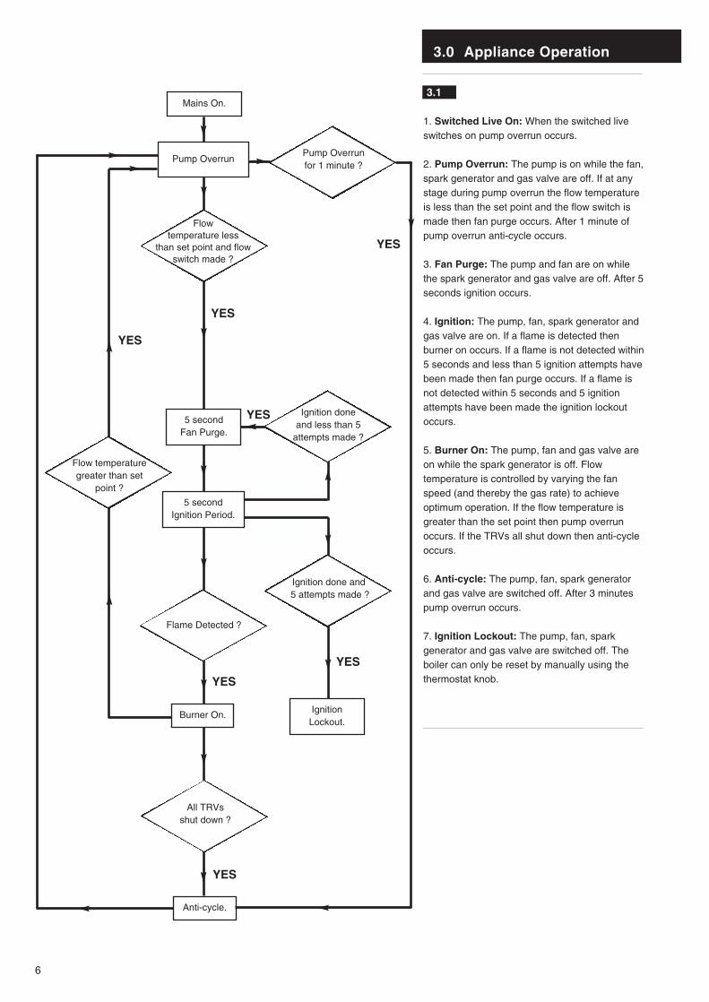
3.1
1. Switched Live On: When the switched liveswitches on pump overrun occurs.
2. Pump Overrun: The pump is on while the fan,spark generator and gas valve are off. If at anystage during pump overrun the flow temperatureis less than the set point and the flow switch ismade then fan purge occurs. After 1 minute ofpump overrun anti-cycle occurs.
3. Fan Purge: The pump and fan are on whilethe spark generator and gas valve are off. After 5seconds ignition occurs.
4. Ignition: The pump, fan, spark generator andgas valve are on. If a flame is detected thenburner on occurs. If a flame is not detected within5 seconds and less than 5 ignition attempts havebeen made then fan purge occurs. If a flame isnot detected within 5 seconds and 5 ignitionattempts have been made the ignition lockoutoccurs.
5. Burner On: The pump, fan and gas valve areon while the spark generator is off. Flowtemperature is controlled by varying the fanspeed (and thereby the gas rate) to achieveoptimum operation. If the flow temperature isgreater than the set point then pump overrunoccurs. If the TRVs all shut down then anti-cycleoccurs.
6. Anti-cycle: The pump, fan, spark generatorand gas valve are switched off. After 3 minutespump overrun occurs.
7. Ignition Lockout: The pump, fan, sparkgenerator and gas valve are switched off. Theboiler can only be reset by manually using thethermostat knob.
Mains On.
Flow temperature less
than set point and flowswitch made ?
YES5 secondFan Purge.
Flame Detected ?
Burner On. IgnitionLockout.
5 secondIgnition Period.
All TRVsshut down ?
Flow temperaturegreater than set
point ?
Ignition done and5 attempts made ?
Ignition done and less than 5
attempts made ?
Pump Overrun
Anti-cycle.
Pump Overrun for 1 minute ?
YES
YES
YES
YES
YES
YES

Appliance Category CAT I 2H
4.0 Technical Data
7
HorizontalFlue Terminal Diameter 110mmDimensions Projection 150mm
Outercase DimensionsOverall Height Inc Flue Elbow - 750mmCasing Height - 600mmCasing Width - 390mmCasing Depth - 320mm
Weights kg lbPackaged Boiler Carton 40.7 89.6Packaged Flue Kit 3.6 8.0Weight Empty 38.2 84.1Installation Lift Weight 31.5 69.3
ConnectionsGas Supply - 1/2 in BSPTCentral Heating Flow - 28mmCentral Heating Return - 28mmCondensate Drain - 1 in BSP
Recommended SystemTemperature Drop
Normal 11°C 20°FCondensing 20°C 36°F
Heat Input Max Min
(see note) kW 33.76 10.2
Btu/h 115,200 34,840
Heat Output (Non Condensing 70° C Mean Water Temp)
Max Min
kW 30.18 9.14
Btu/h 102,980 31,180
Electrical Supply 230V~ 50Hz(Appliance must be connected to an earthed supply)
Power Consumption 80W
External Fuse Rating 3A
Internal Fuse Rating (BS 4265)Fuse (2) 4 AT (Control Board)Fuse (3) 2 AT (Ignition Board)
Max Gas Rate (Natural Gas)(After 10 Mins)
Btu/hr 102,980 75,000
m3/h 2.95 2.31
ft3/h 104.2 81.6
Inlet Pressure at Gas Valve (Natural Gas)Min 18.1 mbar
Max 22.5 mbar
(see Section 10.1)
Injector (Natural Gas)6.3mm Diameter
Clearances (For unventilated compartments see Section 7.5)
Both Sides 5mm MinAbove Casing 200mm MinBelow Casing 50mm MinFront (For Servicing) 500mm MinFront (In Operation) 5mm Min
0 10 20 30 40
204060
80100120140160180200220
Water Flow Rate (litres/min)
Pre
ssur
e D
rop
(mba
r)
0.81.72.5
3.34.25.05.86.67.58.39.1
Pre
ssur
e D
rop
(in w
g)
Hydraulic Resistance Chart
Appliance Type C13 C33 Nox Class 5
Heat Output (Condensing 40° C Mean Water Temp)
Max Min
kW 32.61 10.1
Btu/h 111,280 34,520
Water Content
litres 2.6
pints 4.6
Static Head
max 30 metres (100 ft)
min 1 metre (3.25 ft)
Low Head 0.2m (8 in) min
System Detail fully pumped open vented & sealed systems
Gas Connection RC1/2 (1/2 in BSPT)
Controls boiler thermostat, safety thermostat,flow switch, electronic flame sensing,temperature protection thermostat & condensate blockage sensor
NOTE: The maximum output of theboiler is factory set at 22.0kW(75,000 Btu/hr). This can be alteredto 30.18kW (102,980 Btu/hr) - see section 8.8.
The efficiency is 90.9%
This value is used in the UK Government’s
Standard Assessment Procedure (SAP) for
energy rating of dwellings. The test data from
which it has been calculated has been
certified by 0086.
SEDBUK Declaration For 100 HE

5.0 Dimensions and Fixings
8
DIMENSIONS
A 600mm
B 320mm
C 390mm
D 125mm Ø Min.
E 150mm
F 125mm
SIDE FLUE (left and right)For every 1m of horizontal fluelength, the clearance above thetop of the flue elbow should be55mm to incorporate the 3°(1 in 20) fall in the flue from theterminal to the elbow.
The 3° (1 in 20) fall provided bythe elbow is to allow condensateto run back to the boiler, fordisposal through the condensatedischarge pipe.
Flue length (Y)
up to 1m
1m - 2m
2m - 3m
Clearance (X)
55mm
110mm
165mm
360° Orientation
Tube Ø 110mm
D C
B
A
E
F
Y
3°(1 in 20)
X
3°(1 in 20)
Fig. 6
Fig. 7

6.0 System Details
9
6.1 Water Circulating Systems
1. The appliance is suitable for use with open ventfully pumped systems and sealed systems .The following conditions should be observedon all systems:• The static head must not exceed 30m (100ft)
of water.• The boiler must not be used with a direct
cylinder.• Drain cocks should be fitted to all system low
points.• All gas and water pipes and electrical wiring
must be installed in a way which would not restrict the servicing of the boiler.
• Position isolating valves as close to circulating pump as possible.
• It is recommended that the return pipe is fitted with an automatic air vent as close to the boiler as is practical.
NOTE: Full TRV Systems (refer to section 6.4)Where all the radiators are controlled by TRV’sthen pump protection will be required. This can bedone by either of the options opposite (see Fig A &B). The option shown in Fig. A should only beused on a full TRV system without a bypass.Fig. B shows a system with a bypass that mustbe capable of allowing a flow of at least 3 l/min.
6.2 Treatment of Water Circulating Systems
• All recirculatory water systems will be subject to corrosion unless an appropriate water treatment is applied. This means that the efficiency of the system will deteriorate as corrosion sludge accumulates within the system, risking damage to pump and valves, boiler noise and circulation problems.
• When upgrading existing systems that exhibit evidence of sludging, it is advisable to clean the system prior to treatment in order to remove anysludge and reduce the likelihood of these deposits damaging new components.
• When fitting new systems flux will be evident within the system, which can lead to damage of system components.
• All systems must be thoroughly drained and flushed out. The recommended flushing and cleansing agents are Betz-Dearborn Sentinel X300 or X400 and Fernox Superfloc Universal Cleanser which should be used following the flushing agent manufacturer’s instructions.
• System additives - corrosion inhibitors and flushing agents/descalers should be suitable for aluminium and comply to BS7593 requirements.The only system additives recommended are Betz-Dearborn Sentinel X100 and Fernox-Copalwhich should be used followng the inhibitor manufacturer’s instructions.
Failure to flush and add inhibitor to thesystem will invalidate the appliance warranty.
• It is important to check the inhibitor concentration after installation, system modification and at every service in accordance with the manufacturer’s instructions. (Test kits are available from inhibitor stockists.)
• For information or advice regarding any of the above contact the Baxi Helpline.
Boiler
No demandfor hot water
Centralheatingload
All TRV’s shut down(boiler flow switchcauses pump to stop)
Live feedto pump
Switch live fromprogrammer, etc.
S/L N P/F
Fig. A Wiring to the pump feed connection of boiler
Fig. B Providing a 3 l/min bypass
Boiler
No demandfor hot water
Centralheatingload
All TRV’s shut down(pump continuesaround bypass)
Switch live fromprogrammer,room stat, etc.
S/Ljunction
S/L N P/F3 l/minbypass
BoilerConnections
BoilerConnections
NOTE: This boiler does not require a bypass.
This boiler does not require a permanent live.These diagrams only refer to pump protection for fully TRV’d systems.
6.0 System Details
10
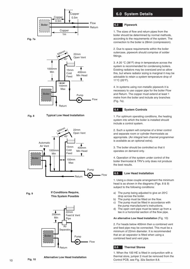
6.3 Pipework
1. The sizes of flow and return pipes from theboiler should be determined by normal methods,according to the requirements of the system. Theconnection to the boiler is 28mm (compression).
2. Due to space requirements within the boileroutercase, pipework should comprise of solderfittings.
3. A 20 °C (36°F) drop in temperature across thesystem is recommended for condensing boilers.Existing radiators may be oversized and so allowthis, but where radiator sizing is marginal it may beadvisable to retain a system temperature drop of11°C (20°F).
4. In systems using non-metallic pipework it isnecessary to use copper pipe for the boiler Flowand Return. The copper must extend at least 1metre from the boiler and include any branches(Fig. 7a).
6.4 System Controls
1. For optimum operating conditions, the heatingsystem into which the boiler is installed shouldinclude a control system.
2. Such a system will comprise of a timer controland separate room or cylinder thermostats asappropriate. (An integral twin channel programmeris available as an optional extra).
3. The boiler should be controlled so that itoperates on demand only.
4. Operation of the system under control of theboiler thermostat & TRV’s only does not producethe best results.
6.5 Low Head Installation
1. Using a close couple arrangement the minimumhead is as shown in the diagrams (Figs. 8 & 9)subject to the following conditions:
a) The pump being adjusted to give an 20oC drop across the boiler.
b) The pump must be fitted on the flow.c) The pump must be fitted in accordance with
the pump manufacturer's instructions.d) The open vent pipe must be taken up from a
tee in a horizontal section of the flow pipe.
An alternative Low Head Installation (Fig. 10)
2. For heads below 400mm then a combined ventand feed pipe may be connected. This must be aminimum of 22mm diameter. It is recommendedthat an air separator is fitted when using acombined feed and vent pipe.
6.6 Thermal Stores
1. When the 100 HE is fitted in conjunction with athermal store, jumper 2 must be removed from theControl PCB, see Fig. 32a Section 8.8.
Typical Low Head Installation
If Conditions Require, This System Possible
Alternative Low Head Installation
Boiler
500mm
45°
22mmOpen Vent
1000mmMin
150mmMax
15mmColdFeed
400mmMin Head
Return
Pump
Flow
Boiler
500mm
45°
22mmOpen Vent
400mmMin Head1000mm
Min
AutomaticAir Vent 15mm
ColdFeed
150mmMax
Return
Pump
Flow
Return
Pump
Flow
Boiler
200mmMin
AirSeparator
22mmFeed & VentPipe
Fig. 8
Fig. 9
Fig. 10
BoilerFlow
Return
Copper0.5m
Copper1m
Copper0.5m
Fig. 7a
6.0 System Details
11
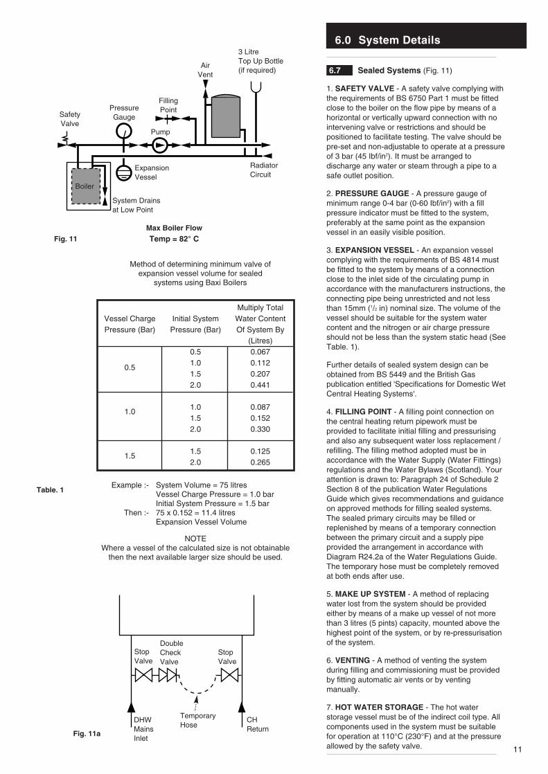
6.7 Sealed Systems (Fig. 11)
1. SAFETY VALVE - A safety valve complying withthe requirements of BS 6750 Part 1 must be fittedclose to the boiler on the flow pipe by means of ahorizontal or vertically upward connection with nointervening valve or restrictions and should bepositioned to facilitate testing. The valve should bepre-set and non-adjustable to operate at a pressureof 3 bar (45 Ibf/in2). It must be arranged todischarge any water or steam through a pipe to asafe outlet position.
2. PRESSURE GAUGE - A pressure gauge ofminimum range 0-4 bar (0-60 Ibf/in2) with a fillpressure indicator must be fitted to the system,preferably at the same point as the expansionvessel in an easily visible position.
3. EXPANSION VESSEL - An expansion vesselcomplying with the requirements of BS 4814 mustbe fitted to the system by means of a connectionclose to the inlet side of the circulating pump inaccordance with the manufacturers instructions, theconnecting pipe being unrestricted and not lessthan 15mm (1/2 in) nominal size. The volume of thevessel should be suitable for the system watercontent and the nitrogen or air charge pressureshould not be less than the system static head (SeeTable. 1).
Further details of sealed system design can beobtained from BS 5449 and the British Gaspublication entitled 'Specifications for Domestic WetCentral Heating Systems'.
4. FILLING POINT - A filling point connection onthe central heating return pipework must beprovided to facilitate initial filling and pressurisingand also any subsequent water loss replacement /refilling. The filling method adopted must be inaccordance with the Water Supply (Water Fittings)regulations and the Water Bylaws (Scotland). Yourattention is drawn to: Paragraph 24 of Schedule 2Section 8 of the publication Water RegulationsGuide which gives recommendations and guidanceon approved methods for filling sealed systems.The sealed primary circuits may be filled orreplenished by means of a temporary connectionbetween the primary circuit and a supply pipeprovided the arrangement in accordance withDiagram R24.2a of the Water Regulations Guide.The temporary hose must be completely removedat both ends after use.
5. MAKE UP SYSTEM - A method of replacingwater lost from the system should be providedeither by means of a make up vessel of not morethan 3 litres (5 pints) capacity, mounted above thehighest point of the system, or by re-pressurisationof the system.
6. VENTING - A method of venting the systemduring filling and commissioning must be providedby fitting automatic air vents or by ventingmanually.
7. HOT WATER STORAGE - The hot waterstorage vessel must be of the indirect coil type. Allcomponents used in the system must be suitablefor operation at 110°C (230°F) and at the pressureallowed by the safety valve.
SafetyValve
PressureGauge
Pump
FillingPoint
AirVent
3 LitreTop Up Bottle(if required)
RadiatorCircuit
ExpansionVessel
System Drainsat Low Point
Max Boiler Flow
Temp = 82° C
Boiler
Fig. 11
Table. 1
Vessel ChargePressure (Bar)
0.5
1.0
1.5
Initial SystemPressure (Bar)
0.51.01.52.0
1.01.52.0
1.52.0
Multiply TotalWater ContentOf System By
(Litres)0.0670.1120.2070.441
0.0870.1520.330
0.1250.265
Method of determining minimum valve ofexpansion vessel volume for sealed
systems using Baxi Boilers
System Volume = 75 litresVessel Charge Pressure = 1.0 barInitial System Pressure = 1.5 bar75 x 0.152 = 11.4 litresExpansion Vessel Volume
Example :-
Then :-
NOTEWhere a vessel of the calculated size is not obtainable
then the next available larger size should be used.
StopValve
DoubleCheckValve
DHWMainsInlet
CHReturn
TemporaryHose
StopValve
Fig. 11a
7.0 Site Requirements
12
7.1 Information
WARNING - Check the information on the dataplate is compatible with local supply conditions.
1. The installation must be carried out by a CORGIRegistered Installer or other registered competentperson and be in accordance with the relevantrequirements of the current GAS SAFETY (Installationand Use) REGULATIONS, the BUILDING REGULATIONS
(Scotland)(Consolidation), the LOCAL BUILDING
REGULATIONS, the current I.E.E. WIRING REGULATIONS
and the bye laws of the LOCAL WATER UNDERTAKING.Where no specific instruction is given referenceshould be made to the relevant BRITISHSTANDARD CODES OF PRACTICE. For Irelandinstall in accordance with IS 813 “INSTALLATION OF
GAS APPLIANCES”. Reference should also be madeto BRITISH GAS GUIDANCE NOTES FOR THE
INSTALLATION OF DOMESTIC GAS CONDENSING BOILERS.
7.2 B.S. Codes of PracticeStandard ScopeBS 6891 Gas Installation.BS 5546 Installation of hot water supplies for
domestic purposes.BS 5449 Part 1 Forced circulation hot water systems.BS 6798 Installation of gas fired hot water boilers.BS 5440 Part 1 Flues.BS 5440 Part 2 Ventilation.BS 7074 Expansion vessels and ancillary
equipment for sealed water systems.BS 7593 Treatment of water in domestic hot water
central heating systems.
WARNING - The addition of anything that mayinterfere with the normal operation of theappliance without the express written permissionof Baxi UK Limited could invalidate the appliancewarranty and infringe the GAS SAFETY
(Installation and Use) REGULATIONS.
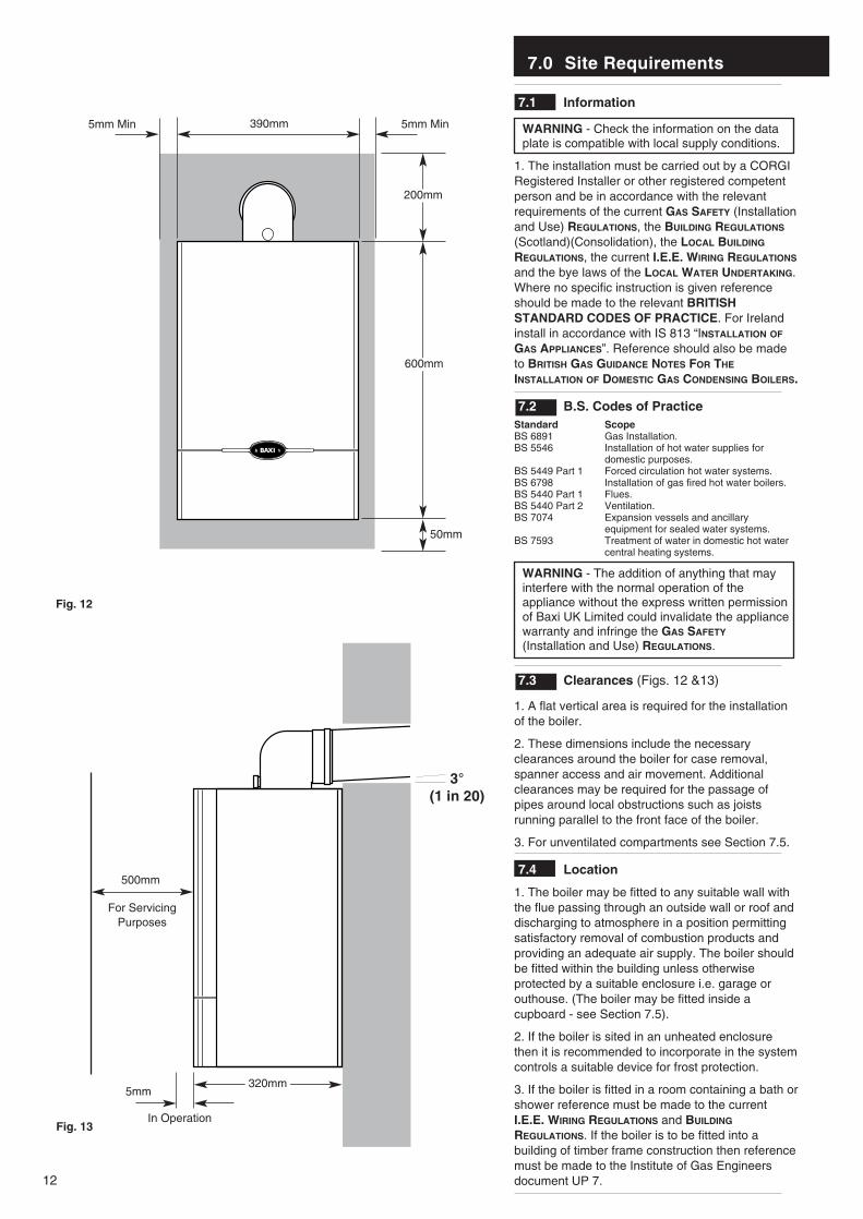
7.3 Clearances (Figs. 12 &13)
1. A flat vertical area is required for the installationof the boiler.
2. These dimensions include the necessaryclearances around the boiler for case removal,spanner access and air movement. Additionalclearances may be required for the passage ofpipes around local obstructions such as joistsrunning parallel to the front face of the boiler.
3. For unventilated compartments see Section 7.5.
7.4 Location
1. The boiler may be fitted to any suitable wall withthe flue passing through an outside wall or roof anddischarging to atmosphere in a position permittingsatisfactory removal of combustion products andproviding an adequate air supply. The boiler shouldbe fitted within the building unless otherwiseprotected by a suitable enclosure i.e. garage orouthouse. (The boiler may be fitted inside acupboard - see Section 7.5).
2. If the boiler is sited in an unheated enclosurethen it is recommended to incorporate in the systemcontrols a suitable device for frost protection.
3. If the boiler is fitted in a room containing a bath orshower reference must be made to the currentI.E.E. WIRING REGULATIONS and BUILDING
REGULATIONS. If the boiler is to be fitted into abuilding of timber frame construction then referencemust be made to the Institute of Gas Engineersdocument UP 7.
50mm
600mm
390mm
200mm
5mm Min5mm Min
5mm
500mm
For ServicingPurposes
Fig. 12
Fig. 13In Operation
3°(1 in 20)
320mm
7.0 Site Requirements
13
7.5 Ventilation of Compartments
1. Where the boiler is installed in a cupboard orcompartment, no air vents are required for coolingpurposes providing that the minimum dimensionsbelow are maintained.
Sides 15mmTop 200mmBottom 50mmFront 30mm
2. If the boiler is installed in a smaller cupboard orcompartment it must be ventilated according toBS 5440 Part 2 and the minimum clearances givenin section 4.0 “Technical Data” maintained.
3. Any compartment should be large enough tohouse the boiler only.
NOTE: The ventilation label on the front of theouter case MUST NOT BE REMOVED whenthe appliance is installed in a compartment orcupboard.
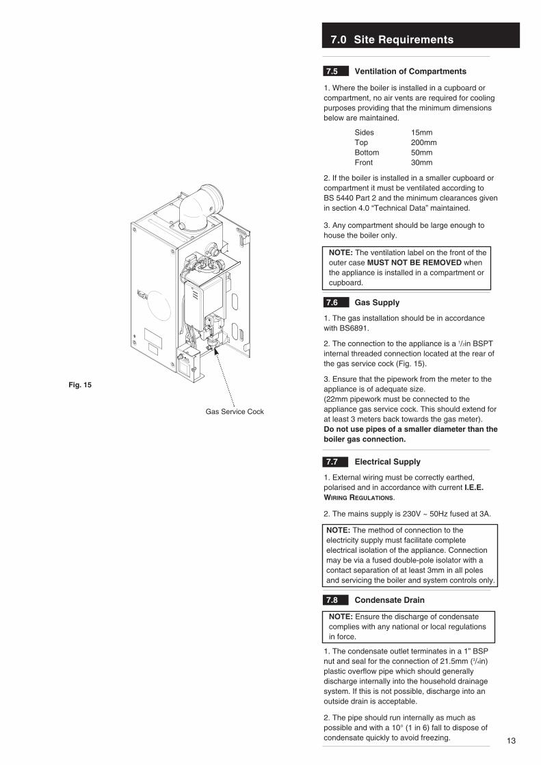
7.6 Gas Supply
1. The gas installation should be in accordancewith BS6891.
2. The connection to the appliance is a 1/2in BSPTinternal threaded connection located at the rear ofthe gas service cock (Fig. 15).
3. Ensure that the pipework from the meter to theappliance is of adequate size. (22mm pipework must be connected to theappliance gas service cock. This should extend forat least 3 meters back towards the gas meter).Do not use pipes of a smaller diameter than theboiler gas connection.
7.7 Electrical Supply
1. External wiring must be correctly earthed,polarised and in accordance with current I.E.E.WIRING REGULATIONS.
2. The mains supply is 230V ~ 50Hz fused at 3A.
NOTE: The method of connection to theelectricity supply must facilitate completeelectrical isolation of the appliance. Connectionmay be via a fused double-pole isolator with acontact separation of at least 3mm in all polesand servicing the boiler and system controls only.
7.8 Condensate Drain
NOTE: Ensure the discharge of condensatecomplies with any national or local regulations in force.
1. The condensate outlet terminates in a 1” BSPnut and seal for the connection of 21.5mm (3/4in)plastic overflow pipe which should generallydischarge internally into the household drainagesystem. If this is not possible, discharge into anoutside drain is acceptable.
2. The pipe should run internally as much aspossible and with a 10° (1 in 6) fall to dispose ofcondensate quickly to avoid freezing.
HIGH
LOW
Gas Service Cock
Fig. 15
7.0 Site Requirements
14
N
I
I
G
F
M
I
AA
F
H
J,K
DE
H
Likely flue positions requiring a flue terminal guard
C
RA
I
J,K
I
L
S
B
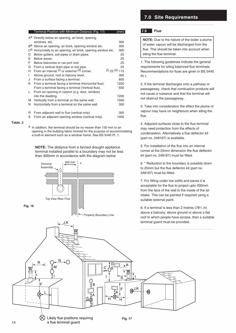
7.9 Flue
NOTE: Due to the nature of the boiler a plumeof water vapour will be discharged from theflue. This should be taken into account whensiting the flue terminal.
1. The following guidelines indicate the generalrequirements for siting balanced flue terminals.Recommendations for flues are given in BS 5440Pt.1.
2. If the terminal discharges onto a pathway orpassageway, check that combustion products willnot cause a nuisance and that the terminal willnot obstruct the passageway.
3. Take into consideration the effect the plume ofvapour may have on neighbours when siting theflue.
4. Adjacent surfaces close to the flue terminalmay need protection from the effects ofcondensation. Alternatively a flue deflector kit(part no. 248167) is available.
5. For installation of the flue into an internalcorner at the 25mm dimension the flue deflectorkit (part no. 248167) must be fitted.
6. * Reduction to the boundary is possible downto 25mm but the flue deflector kit (part no.248167) must be fitted.
7. For fitting under low sofits and eaves it isacceptable for the flue to project upto 500mmfrom the face of the wall to the inside of the airintake. This can be painted if required using asuitable external paint.
8. If a terminal is less than 2 metres (783/4 in)above a balcony, above ground or above a flatroof to which people have access, then a suitableterminal guard must be provided.
Fig. 17
Fig. 16
300 minTerminalAssembly
Top View Rear Flue
Property Boundary Line
NOTE: The distance from a fanned draught applianceterminal installed parallel to a boundary may not be lessthan 300mm in accordance with the diagram below
Table. 2
Terminal Position with Minimum Distance (Fig. 17) (mm)
Aa Directly below an opening, air brick, opening windows, etc. 300
Ba Above an opening, air brick, opening window etc. 300Ca Horizontally to an opening, air brick, opening window etc. 300D Below gutters, soil pipes or drain pipes. 25E Below eaves. 25F Below balconies or car port roof. 25G From a vertical drain pipe or soil pipe. 25H From an internal (i) or external (ii) corner. (i) 25 (ii) 115I Above ground, roof or balcony level. 300J From a surface facing a terminal. 600K From a terminal facing a terminal (Horizontal flue). 1200
From a terminal facing a terminal (Vertical flue). 600L From an opening in carport (e.g. door, window)
into the dwelling. 1200M Vertically from a terminal on the same wall. 1500N Horizontally from a terminal on the same wall. 300
R From adjacent wall to flue (vertical only). 300S From an adjacent opening window (vertical only). 1000
a In addition, the terminal should be no nearer than 150 mm to an opening in the building fabric formed for the purpose of accommodating a built-in element such as a window frame. See BS 5440 Pt. 1.
*

7.0 Site Requirements
15
7.10 Flue Dimensions
See Section 1.2. The standard horizontal flue kitallows for flue lengths between 270mm (105/8”)and 800mm (32”) from elbow to terminal (Fig. 18).
The maximum permissible equivalent fluelength is: 4 metres (Fig. 18a).
NOTE: Each additional 45° of flue bend willaccount for an equivalent flue length of 0.5m.eg. 45° = 0.5m, 90° = 2 x 45° = 1m etc.
7.11 Terminal Guard (Fig. 19)
1. When codes of practice dictate the use ofterminal guards, they can be obtained from mostPlumbers’ and Builders’ Merchants.
2. When ordering a terminal guard, quote theappliance model number.
3. The flue terminal guard should be positionedcentrally over the terminal and fixed asillustrated.
7.12 Vertical Flue
1. Only a flue approved with the Baxi 100 HEcan be used.
2. For information on vertical flues consult theBaxi High Efficiency Brochure or Notes forGuidance supplied with the vertical flue pack.
Fig. 18
Fig. 18a
Pictorial examples of flue runs where EQUIVALENT flue length equals 4m
Fig. 19
270mm
800mm
0.5m
1m
0.5m
0.5m
7.0 Site Requirement
16
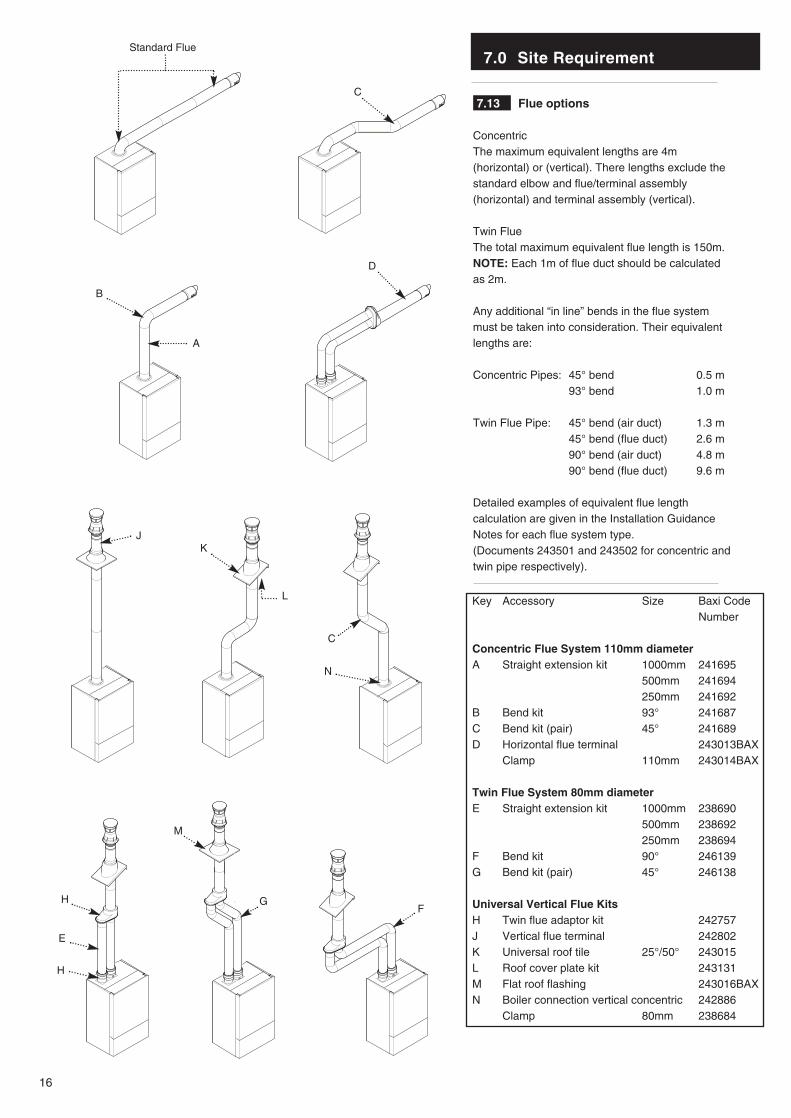
Key Accessory Size Baxi CodeNumber
Concentric Flue System 110mm diameterA Straight extension kit 1000mm 241695
500mm 241694250mm 241692
B Bend kit 93° 241687C Bend kit (pair) 45° 241689D Horizontal flue terminal 243013BAX
Clamp 110mm 243014BAX
Twin Flue System 80mm diameterE Straight extension kit 1000mm 238690
500mm 238692250mm 238694
F Bend kit 90° 246139G Bend kit (pair) 45° 246138
Universal Vertical Flue KitsH Twin flue adaptor kit 242757J Vertical flue terminal 242802K Universal roof tile 25°/50° 243015L Roof cover plate kit 243131M Flat roof flashing 243016BAXN Boiler connection vertical concentric 242886
Clamp 80mm 238684
7.13 Flue options
ConcentricThe maximum equivalent lengths are 4m(horizontal) or (vertical). There lengths exclude thestandard elbow and flue/terminal assembly(horizontal) and terminal assembly (vertical).
Twin FlueThe total maximum equivalent flue length is 150m.NOTE: Each 1m of flue duct should be calculatedas 2m.
Any additional “in line” bends in the flue systemmust be taken into consideration. Their equivalentlengths are:
Concentric Pipes: 45° bend 0.5 m93° bend 1.0 m
Twin Flue Pipe: 45° bend (air duct) 1.3 m45° bend (flue duct) 2.6 m90° bend (air duct) 4.8 m90° bend (flue duct) 9.6 m
Detailed examples of equivalent flue lengthcalculation are given in the Installation GuidanceNotes for each flue system type.(Documents 243501 and 243502 for concentric andtwin pipe respectively).
Standard Flue
C
D
A
B
JK
C
L
H
E
H
M
GF
N
8.0 Installation
17
Check Site Requirements (section 7) beforecommencing.
8.1 Initial Preparation
The gas supply, gas type and pressure mustbe checked for suitability before connection(see Section 7.6).
NOTE: If the boiler wall plate is to be pre-hung, follow both these instructions and thoseon the boiler pack.
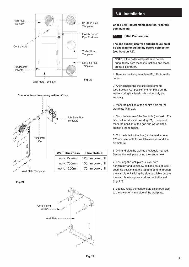
1. Remove the fixing template (Fig. 20) from thecarton.
2. After considering the site requirements (see Section 7.0) position the template on thewall ensuring it is level both horizontally andvertically.
3. Mark the position of the centre hole for thewall plate (Fig. 20).
4. Mark the centre of the flue hole (rear exit). Forside exit, mark as shown (Fig. 21). If required,mark the position of the gas and water pipes.Remove the template.
5. Cut the hole for the flue (minimum diameter125mm, see table for wall thicknesses and fluediameters).
6. Drill and plug the wall as previously marked.Secure the wall plate using the centre hole.
7. Ensuring the wall plate is level bothhorizontally and vertically, drill and plug at least 4securing positions at the top and bottom throughthe wall plate. Utilising the slots available ensurethe wall plate is square and secure to the wall(Fig. 22).
8. Loosely route the condensate discharge pipeto the lower left hand side of the wall plate.
Wall Thickness
up to 227mm
up to 750mm
up to 1200mm
Flue Hole ø
125mm core drill
150mm core drill
175mm core drill
Fig. 20
Fig. 21
Fig. 22
HorizontalLine
Continue these lines along wall for 3° rise
Wall Plate Template
Vertical FlueTemplate
Flow & ReturnPipe Positions
R/H Side FlueTemplate
Rear FlueTemplate
Condensate Collector
Centre Hole
L/H Side FlueTemplate
Wall Plate Template
Wall Plate
R/H Side FlueTemplate
RF
CentralisingScrew
8.0 Installation
18
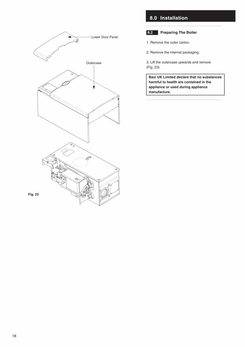
8.2 Preparing The Boiler
1. Remove the outer carton.
2. Remove the internal packaging.
3. Lift the outercase upwards and remove (Fig. 23).
Baxi UK Limited declare that no substancesharmful to health are contained in theappliance or used during appliancemanufacture.
HIGH
LOW
Lower Door Panel
Outercase
Fig. 23
8.0 Installation
19
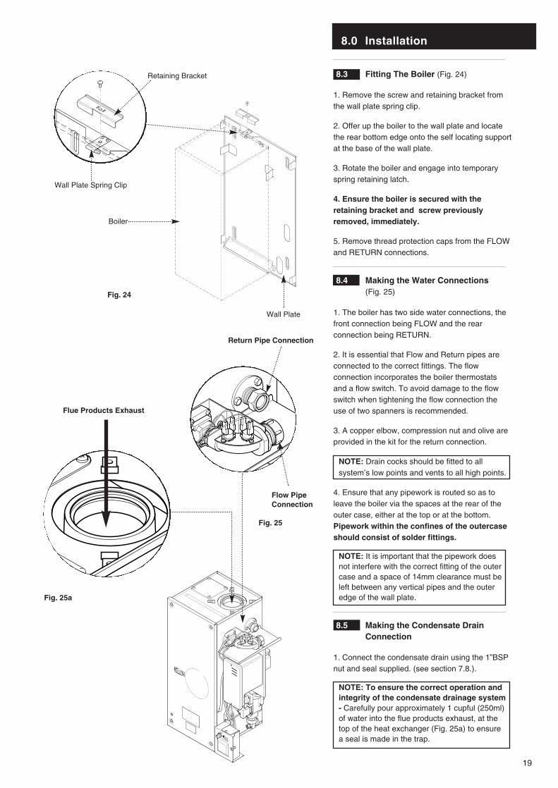
8.3 Fitting The Boiler (Fig. 24)
1. Remove the screw and retaining bracket fromthe wall plate spring clip.
2. Offer up the boiler to the wall plate and locatethe rear bottom edge onto the self locating supportat the base of the wall plate.
3. Rotate the boiler and engage into temporaryspring retaining latch.
4. Ensure the boiler is secured with theretaining bracket and screw previouslyremoved, immediately.
5. Remove thread protection caps from the FLOWand RETURN connections.
8.4 Making the Water Connections(Fig. 25)
1. The boiler has two side water connections, thefront connection being FLOW and the rearconnection being RETURN.
2. It is essential that Flow and Return pipes areconnected to the correct fittings. The flowconnection incorporates the boiler thermostatsand a flow switch. To avoid damage to the flowswitch when tightening the flow connection theuse of two spanners is recommended.
3. A copper elbow, compression nut and olive areprovided in the kit for the return connection.
NOTE: Drain cocks should be fitted to allsystem’s low points and vents to all high points.
4. Ensure that any pipework is routed so as toleave the boiler via the spaces at the rear of theouter case, either at the top or at the bottom.Pipework within the confines of the outercaseshould consist of solder fittings.
NOTE: It is important that the pipework doesnot interfere with the correct fitting of the outercase and a space of 14mm clearance must beleft between any vertical pipes and the outeredge of the wall plate.
8.5 Making the Condensate Drain Connection
1. Connect the condensate drain using the 1”BSPnut and seal supplied. (see section 7.8.).
NOTE: To ensure the correct operation andintegrity of the condensate drainage system- Carefully pour approximately 1 cupful (250ml)of water into the flue products exhaust, at thetop of the heat exchanger (Fig. 25a) to ensurea seal is made in the trap.
HIGH
LOW
Return Pipe Connection
Flow PipeConnection
Boiler
Wall Plate Spring Clip
Wall Plate
Retaining Bracket
Fig. 25
Fig. 24
Flue Products Exhaust
Fig. 25a

8.0 Installation
20
8.6 Making the Gas Connection
1. Connect the gas supply to the RC1/2 (1/2in BSPTinternal) gas tap located on the lower right side ofthe boiler.
8.7 Fitting The Flue
Before fitting the flue, check the condensatedrain integrity (see section 8.5).
IMPORTANT: The flue should always beinstalled with a 3° (1 in 20) fall from terminal toelbow, to allow condensate to run back to theboiler.
HORIZONTAL FLUE
1. The standard flue is suitable for lengths270mm minimum to 800mm maximum (measuredfrom the edge of the flue elbow outlet).
Rear Flue: maximum wall thickness - 630mm
Side Flue: maximum wall thickness - 565mm (left or right)
2. For rear exit - measure the wall thickness (Fig. 26) and to this dimension add 235mm. Thisdimension to be known as (X).i.e.
(X) = wall thickness + 235
3. Take the flue and mark off (X) from theterminal end as indicated in the diagram (Fig. 27).
Check your dimensions.
The flue tubes are fixed together. Cut throughboth tubes whilst resting the flue on the semi-circular packing pieces. Deburr both tube ends.
4. For side exit - measure the distance from theedge of the wall plate to the inner face of the wall(Fig. 26) and to this dimension add the wallthickness + 275mm. This dimension to be knownas (Z).i.e.
(Z) = wall plate to wall + wall thickness + 275
5. Take the flue and mark off (Z) from the terminalend as indicated (Fig. 27).
Check your dimensions.
The flue tubes are fixed together. Cut throughboth tubes whilst resting the flue on the semi-circular packing pieces. Deburr both tube ends.
IMPORTANT: Check all measurements beforecutting.
NOTE: When cutting ensure the cut does notinterfere with the inner flue support bracket(Fig. 27a).
360° Orientation
Inner Flue Support Bracket
Wall Thickness
(Z) Edge of Wall Plate to Wall
Wall Thickness
(Z) = Side Exit(X) = Rear Exit
Flue
Waste
Fig. 26
Fig. 27
Fig. 27a
3°(1 in 20)
8.0 Installation
21
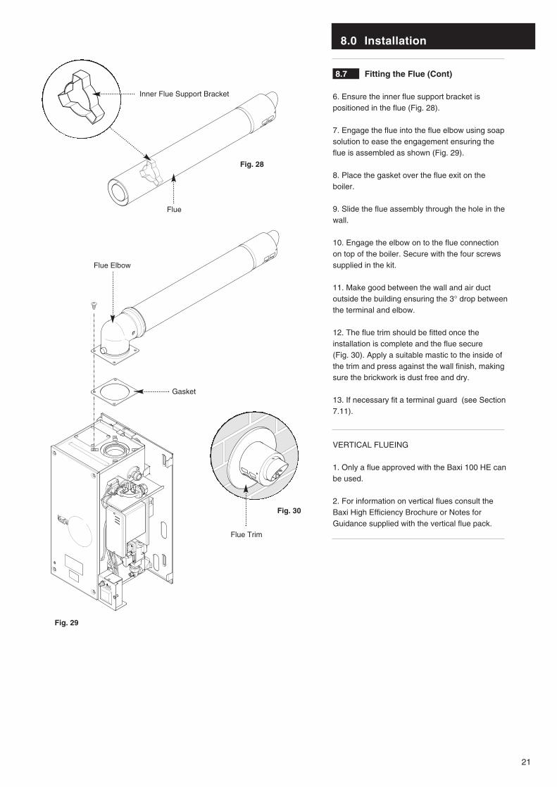
8.7 Fitting the Flue (Cont)
6. Ensure the inner flue support bracket ispositioned in the flue (Fig. 28).
7. Engage the flue into the flue elbow using soapsolution to ease the engagement ensuring theflue is assembled as shown (Fig. 29).
8. Place the gasket over the flue exit on theboiler.
9. Slide the flue assembly through the hole in thewall.
10. Engage the elbow on to the flue connectionon top of the boiler. Secure with the four screwssupplied in the kit.
11. Make good between the wall and air ductoutside the building ensuring the 3° drop betweenthe terminal and elbow.
12. The flue trim should be fitted once theinstallation is complete and the flue secure (Fig. 30). Apply a suitable mastic to the inside ofthe trim and press against the wall finish, makingsure the brickwork is dust free and dry.
13. If necessary fit a terminal guard (see Section7.11).
VERTICAL FLUEING
1. Only a flue approved with the Baxi 100 HE canbe used.
2. For information on vertical flues consult theBaxi High Efficiency Brochure or Notes forGuidance supplied with the vertical flue pack.
HIGH
LOW
Gasket
Flue Trim
Inner Flue Support Bracket
Flue
Flue Elbow
Fig. 28
Fig. 30
Fig. 29
8.0 Installation
22
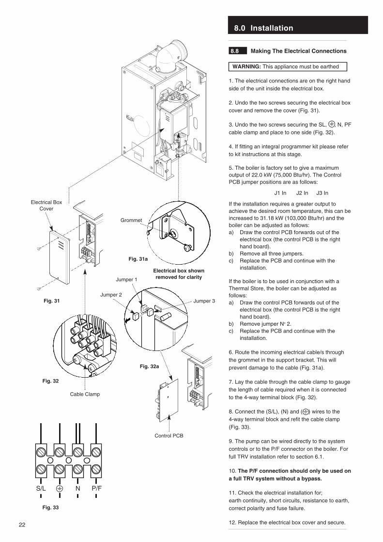
8.8 Making The Electrical Connections
WARNING: This appliance must be earthed
1. The electrical connections are on the right handside of the unit inside the electrical box.
2. Undo the two screws securing the electrical boxcover and remove the cover (Fig. 31).
3. Undo the two screws securing the SL, , N, PFcable clamp and place to one side (Fig. 32).
4. If fitting an integral programmer kit please referto kit instructions at this stage.
5. The boiler is factory set to give a maximumoutput of 22.0 kW (75,000 Btu/hr). The ControlPCB jumper positions are as follows:
J1 In J2 In J3 In
If the installation requires a greater output toachieve the desired room temperature, this can beincreased to 31.18 kW (103,000 Btu/hr) and theboiler can be adjusted as follows:a) Draw the control PCB forwards out of the
electrical box (the control PCB is the right hand board).
b) Remove all three jumpers.c) Replace the PCB and continue with the
installation.
If the boiler is to be used in conjunction with aThermal Store, the boiler can be adjusted asfollows:a) Draw the control PCB forwards out of the
electrical box (the control PCB is the right hand board).
b) Remove jumper No 2.c) Replace the PCB and continue with the
installation.
6. Route the incoming electrical cable/s throughthe grommet in the support bracket. This willprevent damage to the cable (Fig. 31a).
7. Lay the cable through the cable clamp to gaugethe length of cable required when it is connectedto the 4-way terminal block (Fig. 32).
8. Connect the (S/L), (N) and ( ) wires to the 4-way terminal block and refit the cable clamp(Fig. 33).
9. The pump can be wired directly to the systemcontrols or to the P/F connector on the boiler. Forfull TRV installation refer to section 6.1.
10. The P/F connection should only be used ona full TRV system without a bypass.
11. Check the electrical installation for;earth continuity, short circuits, resistance to earth,correct polarity and fuse failure.
12. Replace the electrical box cover and secure.
HIGH
LOW
Fig. 31
Fig. 31a
Fig. 32
Fig. 33
S/L N
Electrical BoxCover
Cable Clamp
Grommet
Electrical box shownremoved for clarity
P/F
Control PCB
Jumper 2
Fig. 32a
Jumper 1
Jumper 3

9.0 Electrical
23
9.1 Schematic Wiring Diagram
Key To Wiring Colours
b - Blue
bk - Black
w - White
br - Brown
v - Violet
r - Red
g - Green
g/y- Green/Yellow
y - Yellow
o - Orange
SparkElectrode
IgnitionPCB
ControlPCB
CondensateTrap
Sensing Electrode
GasValve
Mains Input
Optional Pump Feed
Transformer
Safety Stat
Fan ProtectionStat
Thermistor
Dry FireFlow Switch
DC Fan
Interface PCB
br
r
brw
g/y
g/yg/y
brbb
b
b bk
br br
bk bk
bk
bk bk
r r
rbrgw w v b g y o r bk
N P/F
bk
S/L
bk
Connector with
blue label
b
9.0 Electrical
24
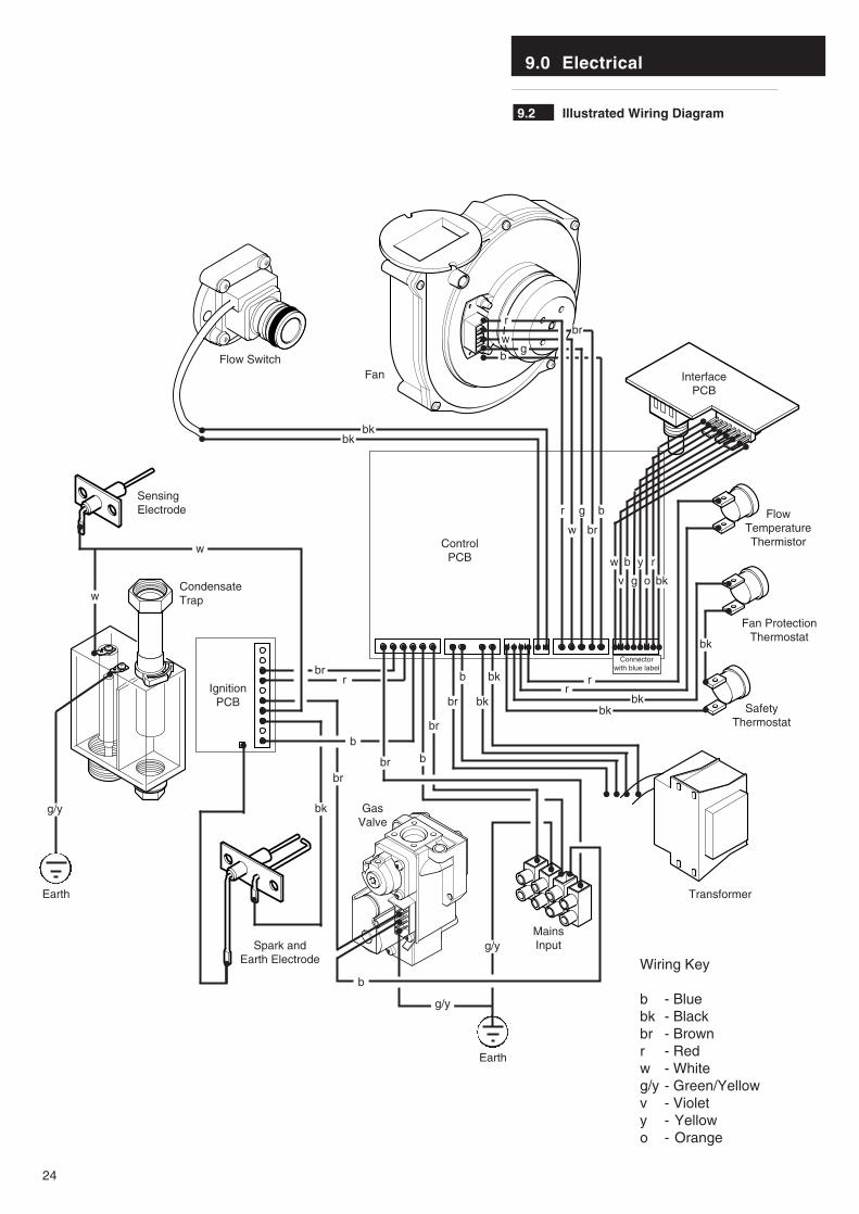
Wiring Key
b - Bluebk - Blackbr - Brownr - Redw - Whiteg/y - Green/Yellowv - Violety - Yellowo - Orange
9.2 Illustrated Wiring Diagram
IgnitionPCB
CondensateTrap
SensingElectrode
bkbk
w
w
brr
b
br
b
br
br
br bkbk
bk
b
w b y r
v g o bk
bk
b bk rr
b
bkg/y
g/y
g/y
Flow SwitchFan
ControlPCB
InterfacePCB
MainsInput
Transformer
SafetyThermostat
Fan ProtectionThermostat
FlowTemperatureThermistor
GasValve
Spark andEarth Electrode
Earth
Earth
r
rbr
w
w
g
g
br
b
Connector with blue label

10.0 Commissioning the Boiler
25
10.1 Commissioning the Boiler
1. Reference should be made to BS 5449Section 5 when commissioning the boiler.
2. Flush the whole system using a suitableflushing agent (see Section 6.2) and vent theradiators. Check for water leaks.
3. Refill the system with inhibitor following theinhibitor manufacturer’s instructions and BS 7593Code of Practice for Treatment of Water inDomestic Hot Water Central Heating Systems(see Section 6.2).
4. Turn the gas supply on and purge the systemaccording to BS 6891.
5. Turn the gas service cock anticlockwise to theON position and check for gas soundness up tothe gas valve (Fig. 34).
6. Turn the boiler control knob fully clockwise to‘HIGH’ (Fig. 35) and run the system and checkthe boiler for correct operation.
NOTE: The boiler is self-regulating and thegas rate will modulate between inputs of33.76kW and 10.2kW dependent upon thesystem load. The input is factory set at24.50kW and can be altered to 33.76kW - seesection 8.8. No adjustment of the gas valveis permissible.
7. With the system cold and all controls callingfor heat check the gas pressure at the inlettapping of the gas valve (Fig. 36). The pressuremust be a minimum of 18.1 mbar.
HIGH
LOW
INO
UT
HIGH
LOW
HIGH
LOW
Gas ServiceCock
ControlKnob
Fig. 34
Fig. 35
Fig. 36
Open
Inlet Gas Pressure Test Point
DO NOT check gas pressure here
/ /
11.0 Fitting the Outer Case
26
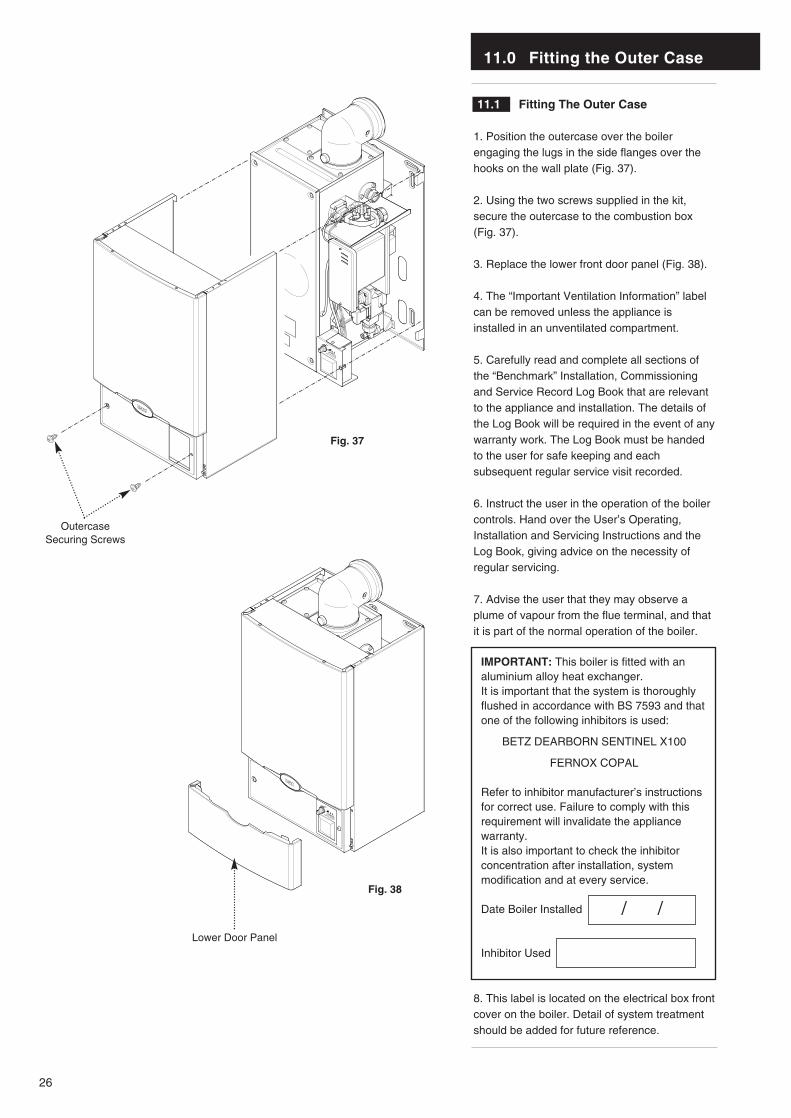
11.1 Fitting The Outer Case
1. Position the outercase over the boilerengaging the lugs in the side flanges over thehooks on the wall plate (Fig. 37).
2. Using the two screws supplied in the kit,secure the outercase to the combustion box(Fig. 37).
3. Replace the lower front door panel (Fig. 38).
4. The “Important Ventilation Information” labelcan be removed unless the appliance isinstalled in an unventilated compartment.
5. Carefully read and complete all sections ofthe “Benchmark” Installation, Commissioningand Service Record Log Book that are relevantto the appliance and installation. The details ofthe Log Book will be required in the event of anywarranty work. The Log Book must be handedto the user for safe keeping and eachsubsequent regular service visit recorded.
6. Instruct the user in the operation of the boilercontrols. Hand over the User’s Operating,Installation and Servicing Instructions and theLog Book, giving advice on the necessity ofregular servicing.
7. Advise the user that they may observe aplume of vapour from the flue terminal, and thatit is part of the normal operation of the boiler.
IMPORTANT: This boiler is fitted with analuminium alloy heat exchanger. It is important that the system is thoroughlyflushed in accordance with BS 7593 and thatone of the following inhibitors is used:
BETZ DEARBORN SENTINEL X100
FERNOX COPAL
Refer to inhibitor manufacturer’s instructionsfor correct use. Failure to comply with thisrequirement will invalidate the appliancewarranty.It is also important to check the inhibitorconcentration after installation, systemmodification and at every service.
Date Boiler Installed
Inhibitor Used
8. This label is located on the electrical box frontcover on the boiler. Detail of system treatmentshould be added for future reference.
HIGH
LOW
HIGH
LOW
OutercaseSecuring Screws
Lower Door Panel
Fig. 37
Fig. 38
12.0 Servicing the Boiler
27
12.1 Annual Servicing
IMPORTANT: When servicing ensure that both thegas and electrical supplies to the boiler are isolatedbefore any work is started.
When the boiler control knob is switched off thecontrol PCB remains live. Therefore it is important toisolate the electrical supply.
Hazardous materials are not used in theconstruction of Baxi products, however reasonablecare during service is recommended.
When replacing the combustion box door afterservicing it is essential that the retaining screws aretightened fully.
1. For reasons of safety and economy, it isrecommended that the boiler is serviced annually.Before servicing please read Section 1.2 ImportantInformation.
2. After servicing, complete the relevant section ofthe “Benchmark” Installation, Commissioning andService Record Log Book. This should be in thepossession of the user.
3. Ensure that the boiler is cool.
4. Ensure that both the gas and electricalsupplies to the boiler are isolated.
5. Remove the outercase and lower door panel(see Fitting the Outercase, Section 11.0).
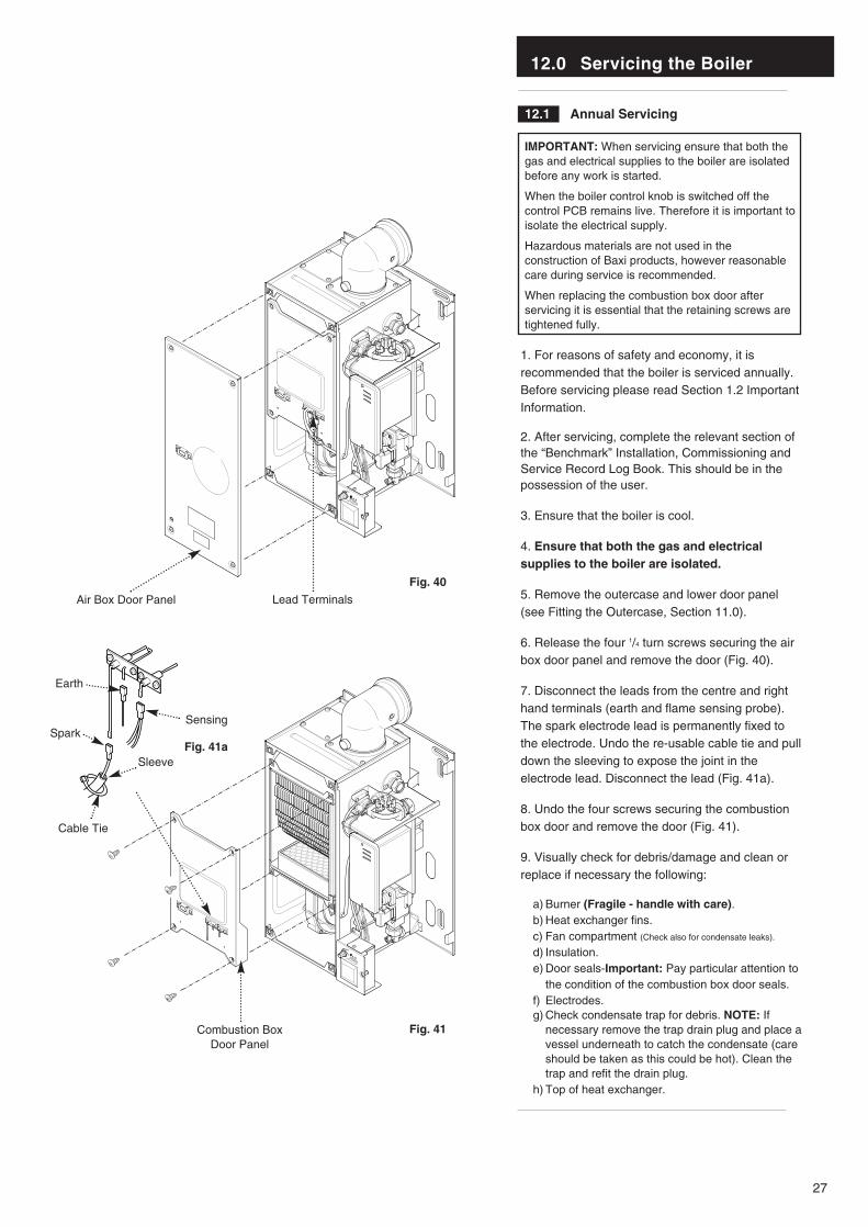
6. Release the four 1/4 turn screws securing the airbox door panel and remove the door (Fig. 40).
7. Disconnect the leads from the centre and righthand terminals (earth and flame sensing probe).The spark electrode lead is permanently fixed tothe electrode. Undo the re-usable cable tie and pulldown the sleeving to expose the joint in theelectrode lead. Disconnect the lead (Fig. 41a).
8. Undo the four screws securing the combustionbox door and remove the door (Fig. 41).
9. Visually check for debris/damage and clean orreplace if necessary the following:
a) Burner (Fragile - handle with care).b) Heat exchanger fins.c) Fan compartment (Check also for condensate leaks).
d) Insulation.e) Door seals-Important: Pay particular attention to
the condition of the combustion box door seals.f) Electrodes.g) Check condensate trap for debris. NOTE: If
necessary remove the trap drain plug and place avessel underneath to catch the condensate (care should be taken as this could be hot). Clean the trap and refit the drain plug.
h) Top of heat exchanger.
HIGH
LOW
HIGH
LOW
Air Box Door Panel Lead Terminals
Combustion BoxDoor Panel
Fig. 40
Fig. 41
Fig. 41a
Cable Tie
Sensing
Earth
Spark
Sleeve
12.0 Servicing the Boiler
28
12.1 Annual Servicing (Cont)
NOTE: General cleaning can beundertaken using a vacuum. Howeverdebris should only be gently blown off theburner skin due to its fragile nature.
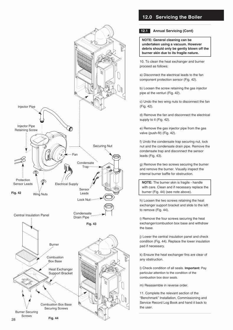
10. To clean the heat exchanger and burnerproceed as follows:
a) Disconnect the electrical leads to the fancomponent protection sensor (Fig. 42).
b) Loosen the screw retaining the gas injectorpipe at the venturi (Fig. 42).
c) Undo the two wing nuts to disconnect the fan(Fig. 42).
d) Remove the fan and disconnect the electricalsupply to it (Fig. 42).
e) Remove the gas injector pipe from the gasvalve (push-fit) (Fig. 42).
f) Undo the condensate trap securing nut, locknut and the condensate drain pipe. Remove thecondensate trap and disconnect the sensorleads (Fig. 43).
g) Remove the two screws securing the burnerand remove the burner. Visually inspect theinternal burner baffle for obstruction.
NOTE: The burner skin is fragile - handlewith care. Clean and if necessary replace theburner (Fig. 44) (see note above).
h) Loosen the two screws retaining the heatexchanger support bracket and slide to the leftto remove (Fig. 44).
i) Remove the four screws securing the heatexchanger/combustion box base and withdrawthe base.
j) Lower the central insulation panel and checkcondition (Fig. 44). Replace the lower insulationpad if necessary.
k) Ensure the heat exchanger fins are clear ofany obstruction.
l) Check condition of all seals. Important: Pay
particular attention to the condition of the
combustion box door seals.
m) Reassemble in reverse order.
11. Complete the relevant section of the“Benchmark” Installation, Commissioning andService Record Log Book and hand it back tothe user.
HIGH
LOW
HIGH
LOW
Combustion Box BaseSecuring Screws
Burner SecuringScrews
Combustion Box Base
Burner
Wing Nuts
Electrical Supply
Lock Nut
Condensate Trap
CondensateDrain Pipe
Securing Nut
Central Insulation Panel
Heat ExchangerSupport Bracket
Injector Pipe
Injector PipeRetaining Screw
Protection Sensor Leads
Fan
Fig. 42
Fig. 44
Fig. 43
SensorLeads
13.0 Changing Components
29
13.1 Changing Components
IMPORTANT: When changing componentsensure that both the gas and electricalsupplies to the boiler are isolated before anywork is started.
When the boiler control knob is switched offthe control PCB remains live. Therefore it isimportant to isolate the electrical supply.
Hazardous materials are not used in theconstruction of Baxi products, howeverreasonable care during service isrecommended.
When replacing the combustion box door afterchanging components, it is essential that theretaining screws are tightened fully.
1. Before changing any components please readSection 1.2 Important Information.
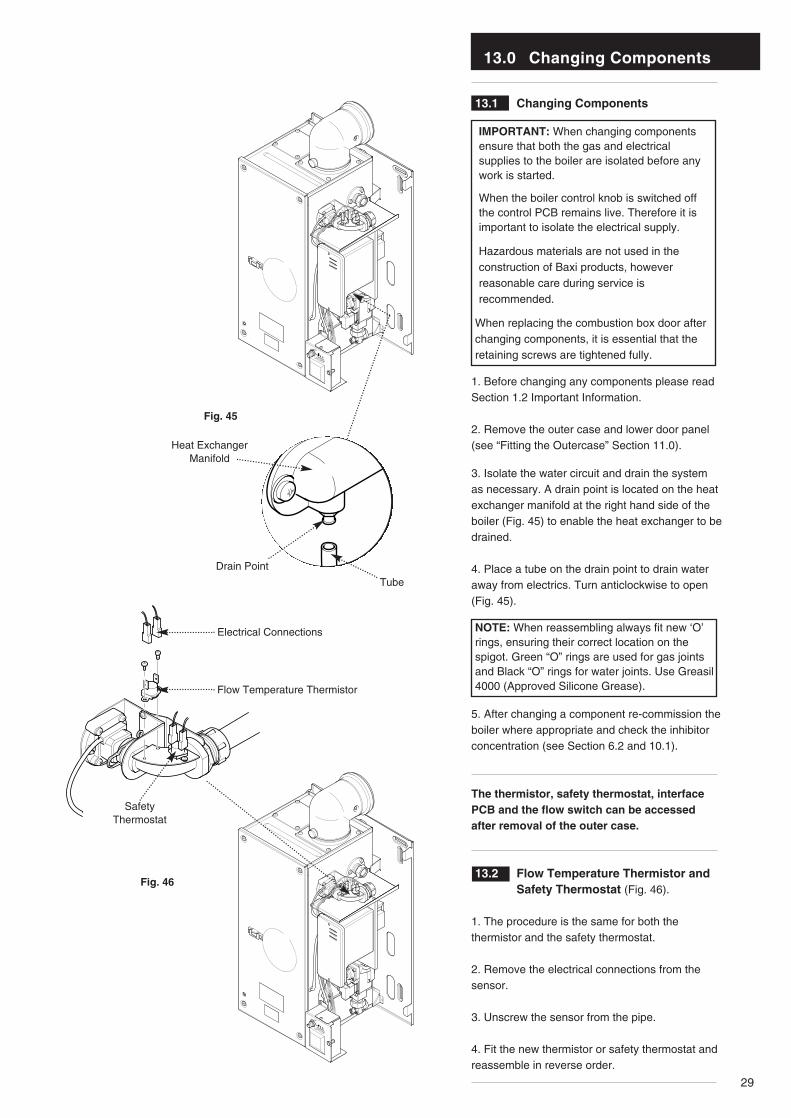
2. Remove the outer case and lower door panel(see “Fitting the Outercase” Section 11.0).
3. Isolate the water circuit and drain the systemas necessary. A drain point is located on the heatexchanger manifold at the right hand side of theboiler (Fig. 45) to enable the heat exchanger to bedrained.
4. Place a tube on the drain point to drain wateraway from electrics. Turn anticlockwise to open(Fig. 45).
NOTE: When reassembling always fit new ‘O’rings, ensuring their correct location on thespigot. Green “O” rings are used for gas jointsand Black “O” rings for water joints. Use Greasil4000 (Approved Silicone Grease).
5. After changing a component re-commission theboiler where appropriate and check the inhibitorconcentration (see Section 6.2 and 10.1).
The thermistor, safety thermostat, interfacePCB and the flow switch can be accessedafter removal of the outer case.
13.2 Flow Temperature Thermistor and Safety Thermostat (Fig. 46).
1. The procedure is the same for both thethermistor and the safety thermostat.
2. Remove the electrical connections from thesensor.
3. Unscrew the sensor from the pipe.
4. Fit the new thermistor or safety thermostat andreassemble in reverse order.
HIGH
LOW
HIGH
LOW
Drain Point
Heat ExchangerManifold
Tube
Electrical Connections
Flow Temperature Thermistor
SafetyThermostat
Fig. 45
Fig. 46
13.0 Changing Components
30
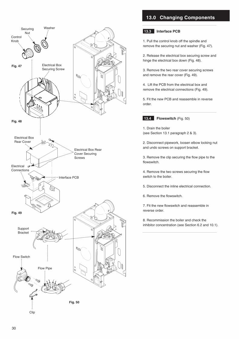
13.3 Interface PCB
1. Pull the control knob off the spindle andremove the securing nut and washer (Fig. 47).
2. Release the electrical box securing screw andhinge the electrical box down (Fig. 48).
3. Remove the two rear cover securing screwsand remove the rear cover (Fig. 49).
4. Lift the PCB from the electrical box andremove the electrical connections (Fig. 49).
5. Fit the new PCB and reassemble in reverseorder.
13.4 Flowswitch (Fig. 50)
1. Drain the boiler (see Section 13.1 paragraph 2 & 3).
2. Disconnect pipework, loosen elbow locking nutand undo screws on support bracket.
3. Remove the clip securing the flow pipe to theflowswitch.
4. Remove the two screws securing the flowswitch to the boiler.
5. Disconnect the inline electrical connection.
6. Remove the flowswitch.
7. Fit the new flowswitch and reassemble inreverse order.
8. Recommission the boiler and check theinhibitor concentration (see Section 6.2 and 10.1).
HIGH
LOW
HIGH
LOW
Electrical BoxSecuring Screw
ControlKnob
SecuringNut
Washer
Interface PCB
ElectricalConnections
Flow Switch
Clip
Flow Pipe
Electrical Box RearCover SecuringScrews
Electrical BoxRear Cover
HIGH
LOW
Fig. 47
Fig. 48
Fig. 49
Fig. 50
SupportBracket
13.0 Changing Components
31
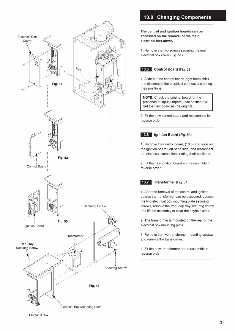
The control and ignition boards can beaccessed on the removal of the mainelectrical box cover.
1. Remove the two screws securing the mainelectrical box cover (Fig. 51).
13.5 Control Board (Fig. 52)
1. Slide out the control board (right hand side)and disconnect the electrical connections notingtheir positions.
NOTE: Check the original board for thepresence of input jumpers - see section 8.8.Set the new board as the original.
2. Fit the new control board and reassemble inreverse order.
13.6 Ignition Board (Fig. 53)
1. Remove the control board, (13.5) and slide outthe ignition board (left hand side) and disconnectthe electrical connections noting their positions.
2. Fit the new ignition board and reassemble inreverse order.
13.7 Transformer (Fig. 54)
1. After the removal of the control and ignitionboards the transformer can be accessed. Loosenthe two electrical box mounting plate securingscrews, remove the front drip tray securing screwand lift the assembly to clear the keyhole slots.
2. The transformer is mounted on the rear of theelectrical box mounting plate.
3. Remove the two transformer mounting screwsand remove the transformer.
4. Fit the new transformer and reassemble inreverse order.
HIGH
LOW
Fig. 51
Fig. 52
Fig. 53
Fig. 54
Transformer
Securing Screw
Securing Screw
Control Board
Ignition Board
Electrical BoxCover
Electrical Box
Electrical Box Mounting Plate
Drip TraySecuring Screw
13.0 Changing Components
32
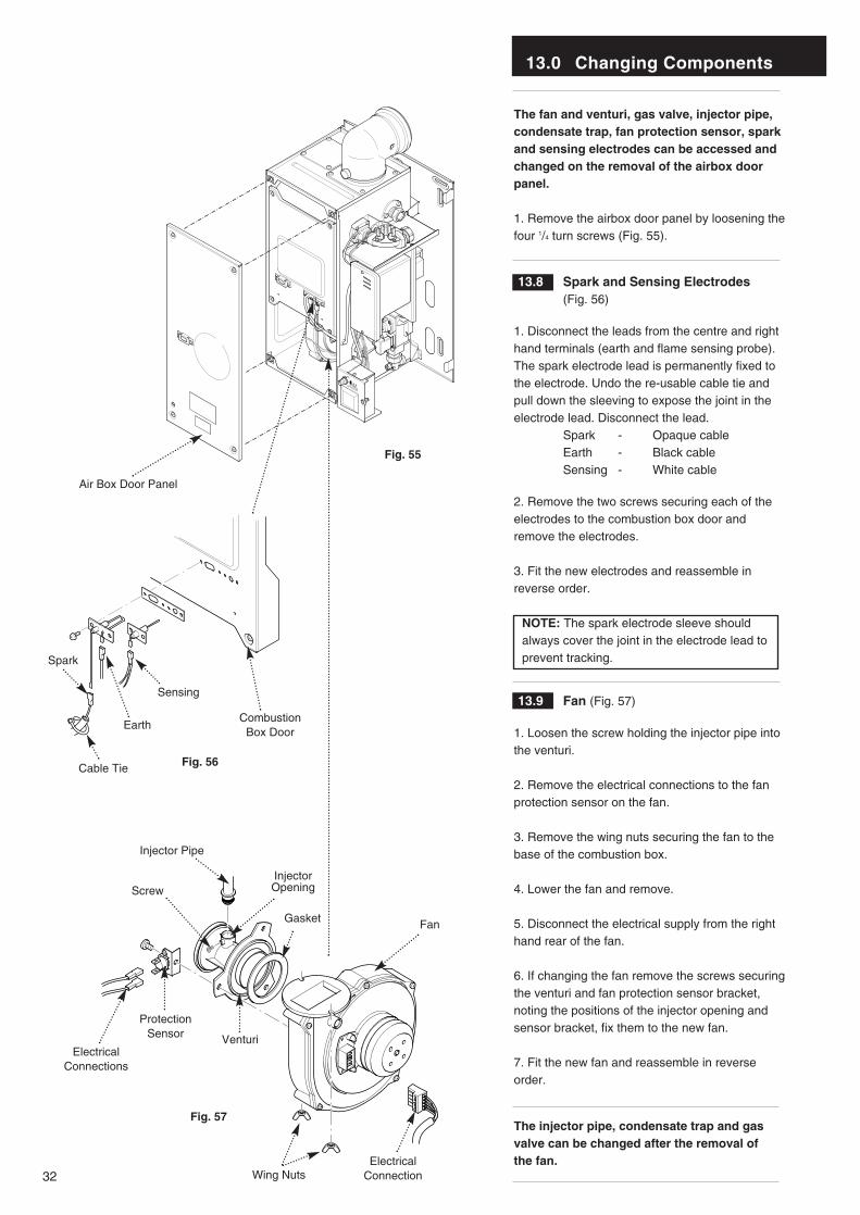
The fan and venturi, gas valve, injector pipe,condensate trap, fan protection sensor, sparkand sensing electrodes can be accessed andchanged on the removal of the airbox doorpanel.
1. Remove the airbox door panel by loosening thefour 1/4 turn screws (Fig. 55).
13.8 Spark and Sensing Electrodes (Fig. 56)
1. Disconnect the leads from the centre and righthand terminals (earth and flame sensing probe).The spark electrode lead is permanently fixed tothe electrode. Undo the re-usable cable tie andpull down the sleeving to expose the joint in theelectrode lead. Disconnect the lead.
Spark - Opaque cableEarth - Black cableSensing - White cable
2. Remove the two screws securing each of theelectrodes to the combustion box door andremove the electrodes.
3. Fit the new electrodes and reassemble inreverse order.
NOTE: The spark electrode sleeve shouldalways cover the joint in the electrode lead toprevent tracking.
13.9 Fan (Fig. 57)
1. Loosen the screw holding the injector pipe intothe venturi.
2. Remove the electrical connections to the fanprotection sensor on the fan.
3. Remove the wing nuts securing the fan to thebase of the combustion box.
4. Lower the fan and remove.
5. Disconnect the electrical supply from the righthand rear of the fan.
6. If changing the fan remove the screws securingthe venturi and fan protection sensor bracket,noting the positions of the injector opening andsensor bracket, fix them to the new fan.
7. Fit the new fan and reassemble in reverseorder.
The injector pipe, condensate trap and gasvalve can be changed after the removal of the fan.
Wing Nuts
Injector Pipe
Screw
ElectricalConnections
ElectricalConnection
Protection Sensor
InjectorOpening
Gasket
Venturi
Fan
HIGH
LOW
Air Box Door Panel
Sensing
Earth
Spark
Combustion Box Door
Fig. 55
Fig. 56
Fig. 57
Cable Tie

13.0 Changing Components
33
The removal of the fan is necessary to enablethe changing of the injector pipe, condensatetrap and gas valve (see section 13.9).
13.10 Injector Pipe (Fig. 58)
1. Remove the injector pipe by pulling out fromthe ‘O’ ring joint in the gas valve.
2. Fit the new injector pipe and reassemble inreverse order.
13.11 Gas Valve (Fig. 58)
1. Release user interface and pivot downward forbetter access.
2. Disconnect the gas inlet union at the gas tap.
3. Undo the case pressure pipe from the gasvalve.
4. Undo the screw and disconnect the electricalplug from the gas valve.
5. Remove the two gas valve securing screwsfrom inside the air box holding the gas valve.
6. Remove the gas valve from the airbox side.
7. Remove the nut union, aluminium spacer andits gasket from the gas valve.
8. Fit the nut union, aluminium spacer and itsgasket to the new valve.
9. Fit the new gas valve and reassemble inreverse order.
13.12 Condensate Trap (Fig. 59)
1. Disconnect the condensate trap from the baseof the heat exchanger.
2. Disconnect the condensate drain (outside theboiler) from the condensate trap.
3. Undo the condensate trap lock nut.
4. Remove the condensate trap from the boiler.
5. Disconnect the sensor leads.
Fit the new condensate trap and reassemble inreverse order.
HIGH
LOW
HIGH
LOW
Injector Pipe
Gas Tap
Case PressurePipe
Boiler Side
Electrical Plug
Gas Valve
Gas Valve Securing Screws
Nut Union
Lock Nut
CondensateDrain Pipe
Condensate Trap
SecuringNut
SensorLeads
Fig. 58
Fig. 59
Aluminium Spacer
‘O ring’
Gasket

13.0 Changing Components
34
The burner and heat exchanger can bechanged after removal of the combustion boxdoor. To change the heat exchanger, the fanand burner must be removed first (see section13.9).
1. Remove the combustion box door by removingthe four securing screws (Fig. 60).
IMPORTANT: On refitting the combustion boxdoor check the condition of the combustionbox door seals.
13.13 Burner (Fig. 61)
WARNING: The burner skin is fragile:Handle with care
1. Remove the two screws securing the burner tothe base of the combustion box.
2. Remove the burner carefully from thecombustion box base.
3. Fit the new burner and reassemble in reverseorder.
13.14 Heat Exchanger
1. Drain the boiler (see section 13.1 paragraph 2 & 3).
2. Remove all components in the base of theairbox.
3. Undo the screws on the support bracket.Remove the screws securing the flow switch andreturn connections and remove the connections(Fig. 64).
4. Remove the electrical connections from theP.C.B.s (see section 13.5 & 13.6).
5. Loosen the two screws securing the electricalbox mounting plate and remove the assembly(Fig. 62).
6. Remove the screws securing the heatexchanger manifold and remove the manifold(Fig. 63).
7. Lift the heat exchanger assembly and rotatethe bottom upwards whilst pulling it forwards outof the airbox.
8. Fit the new heat exchanger and reassemble inreverse order.
9. Recommission the boiler and check theinhibitor concentration (see Section 6.2 and 10.1).
HIGH
LOW
Combustion BoxDoor Panel
Burner
Securing Screws
Fig. 60
Fig. 61
Fig. 62
Fig. 63
Fig. 64
SecuringScrew
Heat ExchangerManifold
Return Connection
FlowSwitch
SecuringScrew
Electrical Box
Heat ExchangerAssembly
Electrical BoxMounting Plate
SupportBracket
13.0 Changing Components
35
Combustion Box Base
Central Insulation Panel
Support Bracket
Burner
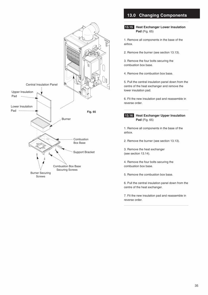
13.15 Heat Exchanger Lower Insulation Pad (Fig. 65)
1. Remove all components in the base of theairbox.
2. Remove the burner (see section 13.13).
3. Remove the four bolts securing thecombustion box base.
4. Remove the combustion box base.
5. Pull the central insulation panel down from thecentre of the heat exchanger and remove thelower insulation pad.
6. Fit the new insulation pad and reassemble inreverse order.
13.16 Heat Exchanger Upper Insulation Pad (Fig. 65)
1. Remove all components in the base of theairbox.
2. Remove the burner (see section 13.13).
3. Remove the heat exchanger (see section 13.14).
4. Remove the four bolts securing thecombustion box base.
5. Remove the combustion box base.
6. Pull the central insulation panel down from thecentre of the heat exchanger.
7. Fit the new insulation pad and reassemble inreverse order.
Combustion Box BaseSecuring Screws
Burner SecuringScrews
HIGH
LOW
Fig. 65
Upper InsulationPad
Lower InsulationPad
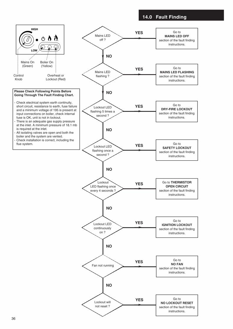
Go to MAINS LED OFF
section of the fault findinginstructions.
YES
NO
Mains LED off ?
14.0 Fault Finding
36
Mains LED flashing ?
Lockout LED flashing 5 times a
second ?
Lockout LED flashing once a
second ?
Lockout LED continuously
on ?
Fan not running
Lockout will not reset ?
Go to MAINS LED FLASHINGsection of the fault finding
instructions.
Go to DRY-FIRE LOCKOUT
section of the fault findinginstructions.
Go to SAFETY LOCKOUT
section of the fault findinginstructions.
Go to IGNITION LOCKOUT
section of the fault findinginstructions.
Go to NO FAN
section of the fault findinginstructions.
Go to NO LOCKOUT RESET
section of the fault findinginstructions.
YES
NO
YES
NO
YES
Lockout LED flashing once every 4 seconds ?
Go to THERMISTOROPEN CIRCUIT
section of the fault findinginstructions.
YES
NO
NO
YES
NO
YES
NO
YES
HIGH
LOW
Overheat orLockout (Red)
Boiler On (Yellow)
Mains On (Green)
ControlKnob
Please Check Following Points BeforeGoing Through The Fault Finding Chart.
- Check electrical system earth continuity, short circuit, resistance to earth, fuse failure and a minimum voltage of 195 is present at input connections on boiler, check internal fuse is OK, unit is not in lockout.
- There is an adequate gas supply pressure at the inlet. A minimum pressure of 18.1 mb is required at the inlet.
- All isolating valves are open and both the boiler and the system are vented.
- Check installation is correct, including the flue system.
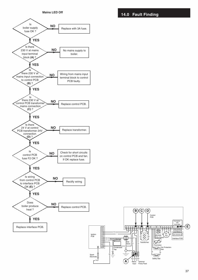
14.0 Fault Finding
37
Is boiler supply
fuse OK ?
Is there230 V at mainsinput terminal
block (A) ?
Is there 230 V at
mains input connectionto control PCB
(B) ?
Is there 230 V at
control PCB transformermains connection
(C) ?
Is control PCB
fuse F2 OK ?
Is wiringfrom control PCBto interface PCB
OK (E) ?
Does boiler produce
heat ?
Replace with 3A fuse.
No mains supply toboiler.
Wiring from mains inputterminal block to control
PCB faulty.
Replace control PCB.
Replace transformer.
Check for short circuitson control PCB and fan.
If OK replace fuse.
Rectify wiring
Replace control PCB.
Replace interface PCB.
YES
NO
Is there24 V at control
PCB transformer 24Vconnection
(D) ?
NO
NO
NO
NO
NO
NO
NO
YES
YES
YES
YES
YES
YES
YES
Mains LED Off
SparkElectrode
IgnitionPCB
ControlPCB
CondensateTrap
Sensing Electrode
GasValve
Mains Input
Optional Pump Feed
Transformer
Safety Stat
Fan ProtectionStat
Thermistor
Dry FireFlow Switch
DC Fan
Interface PCB
br
r
brw
g/y
g/y
brb
b
b
b
b bk
br br
bk bk
bk
bk bk
r r
rbrgw w v b g y o r bk
N P/F
bk
S/L
bk
g/y
Connector with
blue label
A
B C D
E
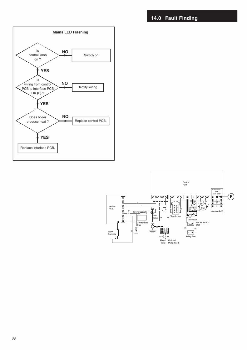
14.0 Fault Finding
38
Is control knob
on ?Switch on
Is wiring from control
PCB to interface PCBOK (F) ?
Does boilerproduce heat ?
Rectify wiring.
Replace control PCB.
Replace interface PCB.
NO
NO
NO
YES
YES
YES
Mains LED Flashing
SparkElectrode
IgnitionPCB
ControlPCB
CondensateTrap
Sensing Electrode
GasValve
Mains Input
Optional Pump Feed
Transformer
Safety Stat
Fan ProtectionStat
Thermistor
Dry FireFlow Switch
DC Fan
Interface PCB
br
r
brw
g/y
g/y
brb
b
b
b
b bk
br br
bk bk
bk
bk bk
r r
rbrgw w v b g y o r bk
N P/F
bk
S/L
bk
g/y
Connector with
blue label
F
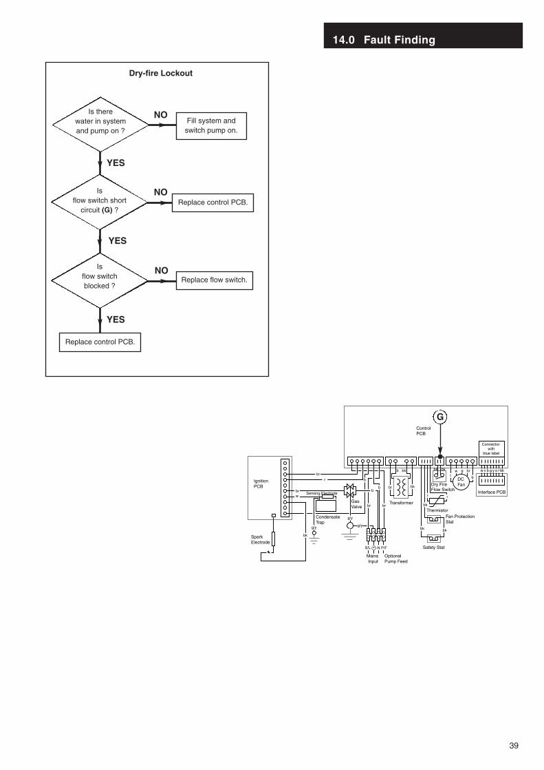
14.0 Fault Finding
39
Fill system andswitch pump on.
Replace control PCB.
Replace flow switch.
Replace control PCB.
Is there water in systemand pump on ?
Is flow switch short
circuit (G) ?
Is flow switchblocked ?
Dry-fire Lockout
NO
NO
NO
YES
YES
YES
SparkElectrode
IgnitionPCB
ControlPCB
CondensateTrap
Sensing Electrode
GasValve
Mains Input
Optional Pump Feed
Transformer
Safety Stat
Fan ProtectionStat
Thermistor
Dry FireFlow Switch
DC Fan
Interface PCB
br
r
brw
g/y
g/y
brb
b
b
b
b bk
br br
bk bk
bk
bk bk
r r
rbrgw w v b g y o r bk
N P/F
bk
S/L
bk
g/y
Connector with
blue label
G
Wiring fromthermistor to logic
PCB faulty
YES
14.0 Fault Finding
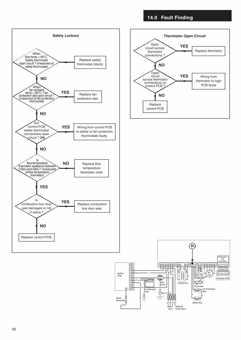
40
When fan ambient
temp < 90°C. Fan protection stat open circuit ?(measured at fan protection
thermostat)
Replace safetythermostat (black)
Replace fanprotection stat.
Are control PCB
safety thermostatconnections open
circuit ? (H)
Wiring from control PCBto safety or fan protection
thermostats faulty.
Replace flowtemperature
thermistor (red)
Is combustion box doorseal damaged or not
in place ?
Replace combustionbox door seal.
Replace control PCB.
When flow temp < 60°C. Safety thermostat
open circuit ? (measured atsafety thermostat)
NO
YES
YES
NO
NO
NO
YES
YES
NO
Safety Lockout
Open circuit across
thermistor connections ?
Open circuit
across thermistor connections on control PCB ?
Replace thermistorYES
NO
NO
Thermistor Open Circuit
Is flow temperature
thermistor resistance between0.5kΩ and 20kΩ ? (measured
at flow temperature thermistor)
SparkElectrode
IgnitionPCB
ControlPCB
CondensateTrap
Sensing Electrode
GasValve
Mains Input
Optional Pump Feed
Transformer
Safety Stat
Fan ProtectionStat
Thermistor
Dry FireFlow Switch
DC Fan
Interface PCB
br
r
brw
g/y
g/y
brb
b
b
b
b bk
br br
bk bk
bk
bk bk
r r
rbrgw w v b g y o r bk
N P/F
bk
S/L
bk
g/y
Connector with
blue label
H
Replacecontrol PCB

14.0 Fault Finding
41
Flow overheatthermostat will not
reset until flowtemperature < 60° C.
Is flow temperature
> 60° C ?
Fan protectionthermostat will notreset until casing
temperature < 90° C.
Is fan ambient
temperature > 90° C ?
Dry-fire lockout cannotbe reset until there iswater in the systemand the pump is on.
Is water in system and
pump on ?
Replace interface PCB.
Control knob switch short
circuit when on andopen circuit when
off ? (K)
Wiring from control PCBto interface PCB faulty.
Control PCB control knob
switch pins short circuitwhen on and open
circuit when off ? (J)
Replace control PCB.
YES
YES
YES
NO
NO
NO
NO
No Lockout ResetNo Fan
YES
YES
NO
NO
Is flow temperature
thermistor between 0.5kΩand 20kΩ ? (measured at
flow temperaturethermistor)
Replace flowtemperature
thermistor (red)
Is control PCB
sensor connections0.5kΩ to 20kΩ ? (I)
Wiring from controlPCB to sensor faulty.
Replace control PCB.
SparkElectrode
IgnitionPCB
ControlPCB
CondensateTrap
Sensing Electrode
GasValve
Mains Input
Optional Pump Feed
Transformer
Safety Stat
Fan ProtectionStat
Thermistor
Dry FireFlow Switch
DC Fan
Interface PCB
br
r
brw
g/y
g/y
brb
b
b
b
b bk
br br
bk bk
bk
bk bk
r r
rbrgw w v b g y o r bk
N P/F
bk
S/L
bk
g/y
Connector with
blue label
I
J
K
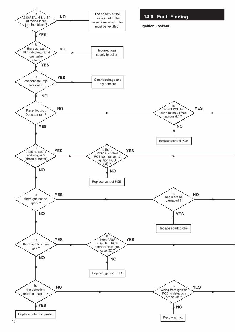
14.0 Fault Finding
42
Is 230V S/L-N & L-E
at mains inputterminal block ?
The polarity of themains input to the
boiler is reversed. Thismust be rectified.
Is there at least
18.1 mb dynamic atgas valve
inlet ?
Incorrect gassupply to boiler.
Reset lockout.Does fan run ?
Is control PCB fan
connection 24 Vac across (L) ?
Replace control PCB.
Is there no spark and no gas ?
(check at meter)
Is there 230V at control
PCB connection to ignition PCB
(M) ?
Is there gas but no
spark ?
Is spark probe damaged ?
Replace spark probe.
Is there spark but no
gas ?
Is there 230V
at ignition PCBconnection to gas
valve (O) ?
Replace ignition PCB.
Replace control PCB.
Is the detection
probe damaged ?
Is wiring from ignitionPCB to detection
probe OK ?
Rectify wiring.Replace detection probe.
Ignition Lockout
NO
YES
NO
Is condensate trap
blocked ?
Clear blockage anddry sensors
YES
NO
NO
NO
YES
YES
YES
YESYES
NO
YES
YES
NO
NO
NO
NO NO
YES YES
YES
YES
NO
NO
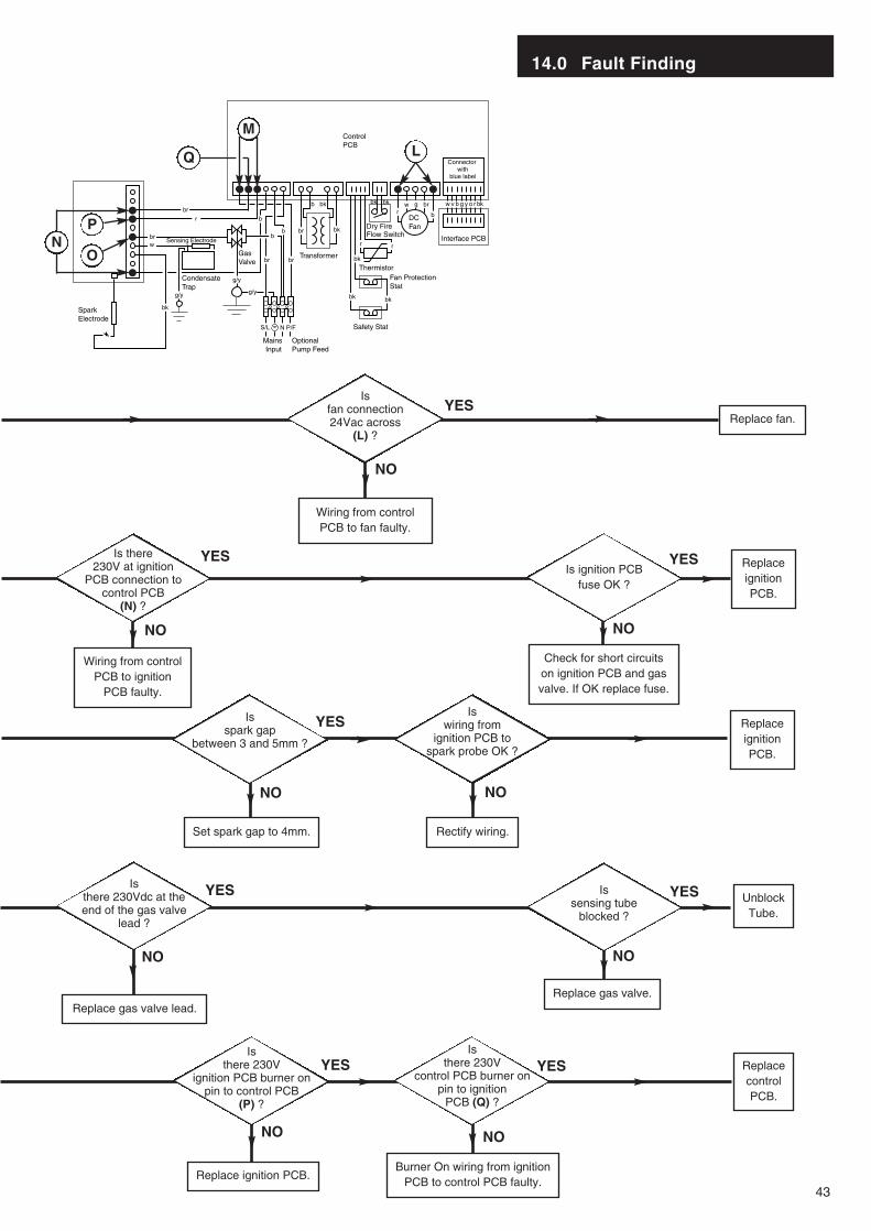
43
14.0 Fault Finding
Replace fan.
Is fan connection24Vac across
(L) ?
Wiring from controlPCB to fan faulty.
Is ignition PCBfuse OK ?
ReplaceignitionPCB.
ReplaceignitionPCB.
Is there 230V at ignition
PCB connection to control PCB
(N) ?
Wiring from controlPCB to ignition
PCB faulty.
Check for short circuitson ignition PCB and gasvalve. If OK replace fuse.
Is wiring from
ignition PCB tospark probe OK ?
Is spark gap
between 3 and 5mm ?
Set spark gap to 4mm. Rectify wiring.
Is sensing tube
blocked ?
UnblockTube.
Is there 230Vdc at theend of the gas valve
lead ?
Replace gas valve lead.Replace gas valve.
ReplacecontrolPCB.
Is there 230V
ignition PCB burner onpin to control PCB
(P) ?
Replace ignition PCB.Burner On wiring from ignition
PCB to control PCB faulty.
Is there 230V
control PCB burner onpin to ignition
PCB (Q) ?
NO
YES
YES
NO NO
YES
YES
NO NO
NO NO
YES YES
YESYES
NO NO
SparkElectrode
IgnitionPCB
ControlPCB
CondensateTrap
Sensing Electrode
GasValve
Mains Input
Optional Pump Feed
Transformer
Safety Stat
Fan ProtectionStat
Thermistor
Dry FireFlow Switch
DC Fan
Interface PCB
br
r
brw
g/y
g/y
brb
b
b
b
b bk
br br
bk bk
bk
bk bk
r r
rbrgw w v b g y o r bk
N P/F
bk
S/L
bk
g/y
Connector with
blue label
L
M
Q
NP
O

15.0 Short Parts List
44
Short Parts List
Key G.C. Description ManufacturersNo. No. Part No.
1 E06 058 Flow Temperature
Thermistor (Red) 240670
2 E06 059 Flow Switch 242459
3 E06 060 Safety Thermostat
(Black) 242235
8 E06 064 Control PCB 5106789
9 E06 065 Ignition PCB 241838
10 E06 066 Transformer 240236
21 E06 074 Fan 242472
23 E06 075 Gas Valve 242473
28 E06 079 Interface PCB 241839
38 E06 085 Viewing Window 242484
39 E06 086 Condensate Trap 242485
44 E06 091 Electrodes Kit 242490
47 E06 093 Burner Assy 242492
52 E06 097 Heat Exchanger Assy 242497
1 2 3
89
1021
23
2838
39
44
47
52

16.0 Notes
45

16.0 Notes
46
47
Baxi UK Limited manufacture a comprehensive rangeof products for the domestic heating market.
Gas Central Heating Boilers(Wall, Floor and Fireside models).
Independent Gas Fires.
Renewal Firefronts.
Gas Wall Heaters.
Solid Fuel Fires.
If you require information on any of these products,please write, telephone or fax to the Sales Department.

Baxi UK LimitedBrownedge Road
Bamber Bridge PrestonLancashirePR5 6SN
www.baxi.com
After Sales Service08706 096 096
Technical Enquiries08706 049 049
Comp No 5106739 - Iss 4 - 9/02