Embed Size (px)
Citation preview
Manuale di assemblaggio per porte scorrevoli.
Assembly handbook for sliding doors.
Manuel pour l’assemblage pour portes coulissantes.
Zusammenbauanleitung für Schiebtürantrieb.
Manual de ensemblaje para puertas correderas.
Manual de assemblagem para portas deslizantes.
KIT REXIP1837 - rev. 2007-07-17
P
E
D
F
GB
I
DITEC S.p.A.Via Mons. Banfi, 3 - 21042 Caronno Pertusella (VA) - ITALYTel. +39 02 963911 - Fax +39 02 9650314 www.ditec.it - [email protected]
2KIT REX - IP1837
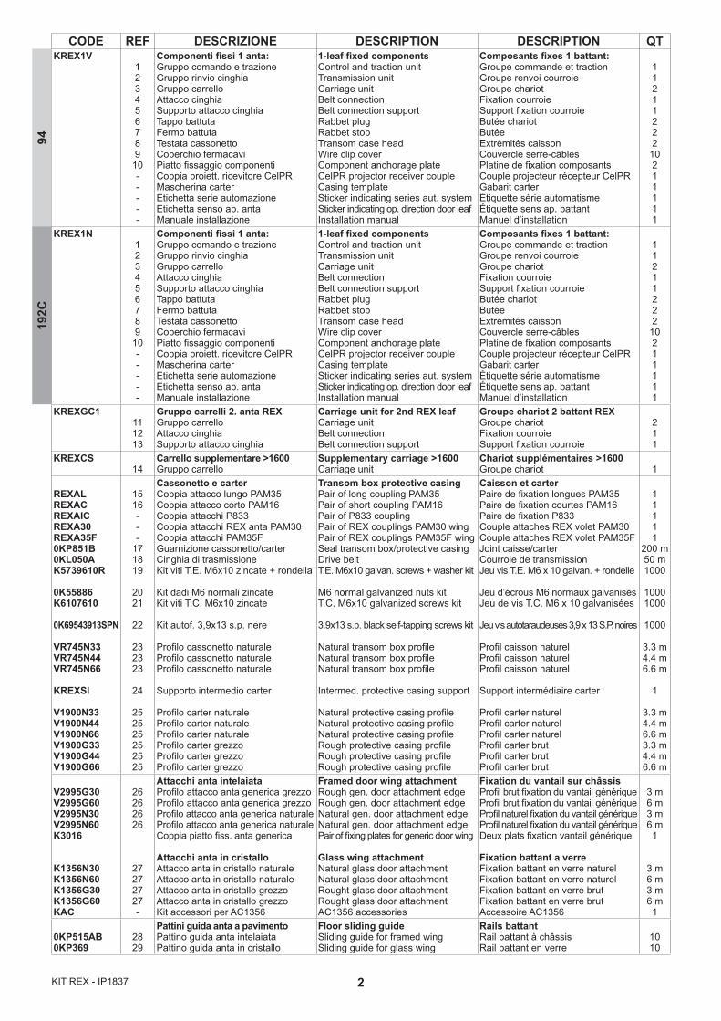
CODE REF DESCRIZIONE DESCRIPTION DESCRIPTION QTKREX1V
123456789
10-----
Componenti fissi 1 anta:Gruppo comando e trazioneGruppo rinvio cinghiaGruppo carrelloAttacco cinghiaSupporto attacco cinghiaTappo battutaFermo battutaTestata cassonettoCoperchio fermacavi Piatto fissaggio componentiCoppia proiett. ricevitore CelPRMascherina carterEtichetta serie automazioneEtichetta senso ap. anta Manuale installazione
1-leaf fixed componentsControl and traction unitTransmission unitCarriage unitBelt connectionBelt connection supportRabbet plugRabbet stopTransom case headWire clip coverComponent anchorage plateCelPR projector receiver coupleCasing templateSticker indicating series aut. system Sticker indicating op. direction door leafInstallation manual
Composants fixes 1 battant:Groupe commande et tractionGroupe renvoi courroieGroupe chariotFixation courroieSupport fixation courroieButée chariotButéeExtrémités caissonCouvercle serre-câblesPlatine de fixation composantsCouple projecteur récepteur CelPRGabarit carterÉtiquette série automatismeÉtiquette sens ap. battantManuel d’installation
11211222
10211111
KREX1N123456789
10-----
Componenti fissi 1 anta:Gruppo comando e trazioneGruppo rinvio cinghiaGruppo carrelloAttacco cinghiaSupporto attacco cinghiaTappo battutaFermo battutaTestata cassonettoCoperchio fermacavi Piatto fissaggio componentiCoppia proiett. ricevitore CelPRMascherina carterEtichetta serie automazioneEtichetta senso ap. anta Manuale installazione
1-leaf fixed componentsControl and traction unitTransmission unitCarriage unitBelt connectionBelt connection supportRabbet plugRabbet stopTransom case headWire clip coverComponent anchorage plateCelPR projector receiver coupleCasing templateSticker indicating series aut. system Sticker indicating op. direction door leafInstallation manual
Composants fixes 1 battant:Groupe commande et tractionGroupe renvoi courroieGroupe chariotFixation courroieSupport fixation courroieButée chariotButéeExtrémités caissonCouvercle serre-câblesPlatine de fixation composantsCouple projecteur récepteur CelPRGabarit carterÉtiquette série automatismeÉtiquette sens ap. battantManuel d’installation
11211222
10211111
KREXGC1111213
Gruppo carrelli 2. anta REXGruppo carrelloAttacco cinghiaSupporto attacco cinghia
Carriage unit for 2nd REX leafCarriage unitBelt connectionBelt connection support
Groupe chariot 2 battant REXGroupe chariotFixation courroieSupport fixation courroie
211
KREXCS14
Carrello supplementare >1600Gruppo carrello
Supplementary carriage >1600Carriage unit
Chariot supplémentaires >1600Groupe chariot 1
REXALREXACREXAICREXA30REXA35F0KP851B0KL050AK5739610R
0K55886K6107610
0K69543913SPN
VR745N33VR745N44VR745N66
KREXSI
V1900N33V1900N44V1900N66V1900G33V1900G44V1900G66
1516---
171819
2021
22
232323
24
252525252525
Cassonetto e carterCoppia attacco lungo PAM35Coppia attacco corto PAM16Coppia attacchi P833Coppia attacchi REX anta PAM30Coppia attacchi PAM35FGuarnizione cassonetto/carterCinghia di trasmissioneKit viti T.E. M6x10 zincate + rondella
Kit dadi M6 normali zincateKit viti T.C. M6x10 zincate
Kit autof. 3,9x13 s.p. nere
Profilo cassonetto naturaleProfilo cassonetto naturaleProfilo cassonetto naturale
Supporto intermedio carter
Profilo carter naturaleProfilo carter naturaleProfilo carter naturaleProfilo carter grezzoProfilo carter grezzoProfilo carter grezzo
Transom box protective casingPair of long coupling PAM35Pair of short coupling PAM16Pair of P833 couplingPair of REX couplings PAM30 wingPair of REX couplings PAM35F wingSeal transom box/protective casingDrive beltT.E. M6x10 galvan. screws + washer kit
M6 normal galvanized nuts kitT.C. M6x10 galvanized screws kit
3.9x13 s.p. black self-tapping screws kit
Natural transom box profile Natural transom box profileNatural transom box profile
Intermed. protective casing support
Natural protective casing profileNatural protective casing profileNatural protective casing profileRough protective casing profileRough protective casing profileRough protective casing profile
Caisson et carter Paire de fixation longues PAM35Paire de fixation courtes PAM16Paire de fixation P833Couple attaches REX volet PAM30Couple attaches REX volet PAM35FJoint caisse/carterCourroie de transmissionJeu vis T.E. M6 x 10 galvan. + rondelle
Jeu d’écrous M6 normaux galvanisésJeu de vis T.C. M6 x 10 galvanisées
Jeu vis autotaraudeuses 3,9 x 13 S.P. noires Profil caisson naturelProfil caisson naturelProfil caisson naturel
Support intermédiaire carter
Profil carter naturelProfil carter naturelProfil carter naturelProfil carter brutProfil carter brutProfil carter brut
11111
200 m50 m1000
10001000
1000
3.3 m4.4 m6.6 m
1
3.3 m4.4 m6.6 m3.3 m4.4 m6.6 m
V2995G30V2995G60V2995N30V2995N60K3016
K1356N30K1356N60K1356G30K1356G60KAC
26262626
27272727-
Attacchi anta intelaiataProfilo attacco anta generica grezzoProfilo attacco anta generica grezzoProfilo attacco anta generica naturaleProfilo attacco anta generica naturaleCoppia piatto fiss. anta generica
Attacchi anta in cristalloAttacco anta in cristallo naturaleAttacco anta in cristallo naturaleAttacco anta in cristallo grezzoAttacco anta in cristallo grezzoKit accessori per AC1356
Framed door wing attachmentRough gen. door attachment edgeRough gen. door attachment edgeNatural gen. door attachment edgeNatural gen. door attachment edgePair of fixing plates for generic door wing
Glass wing attachmentNatural glass door attachment Natural glass door attachment Rought glass door attachment Rought glass door attachmentAC1356 accessories
Fixation du vantail sur châssisProfil brut fixation du vantail génériqueProfil brut fixation du vantail génériqueProfil naturel fixation du vantail génériqueProfil naturel fixation du vantail génériqueDeux plats fixation vantail générique
Fixation battant a verreFixation battant en verre naturelFixation battant en verre naturelFixation battant en verre brutFixation battant en verre brutAccessoire AC1356
3 m6 m3 m6 m1
3 m6 m3 m6 m1
0KP515AB0KP369
2829
Pattini guida anta a pavimentoPattino guida anta intelaiataPattino guida anta in cristallo
Floor sliding guideSliding guide for framed wingSliding guide for glass wing
Rails battantRail battant à châssisRail battant en verre
1010
9419
2C

3 KIT REX - IP1837
CODE REF DESCRIZIONE DESCRIPTION DESCRIPTION QT
0KZ18REXLOKSBMREXAB
30-
32
AccessoriBlocco di sicurezzaSblocco supplementareAntipanico a batterie
AccessoriesSafety lockSupplementary release deviceAntipanic with battery
AccessoiresBlocage de sécurité avec déblocageDéblocage supplémentaireAntipanique à batterie
--1
VSP14V25 31SpazzoliniSpazzolini di tenuta
BrushesSealing brushes
BrossesBrosse d’étanchéité 2.5 m
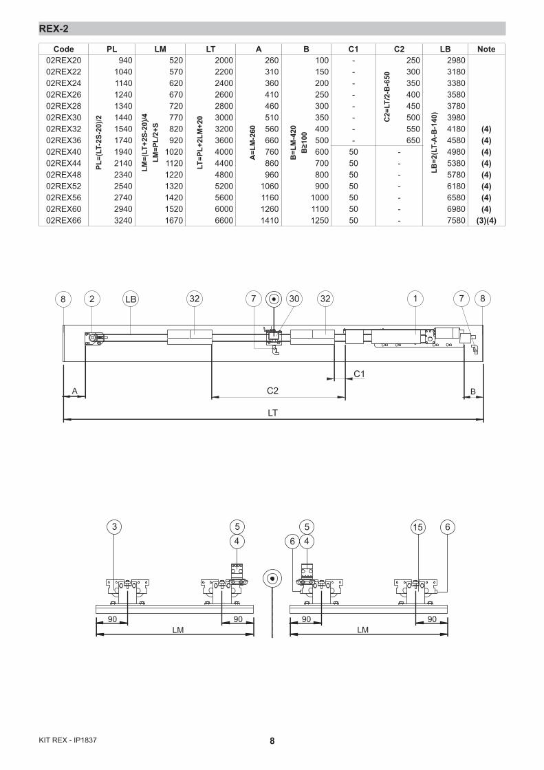
LEGENDAPL = Vano passaggio orizzontaleLM = Lunghezza anta mobileLT = Lunghezza totale automazioneLB = Lunghezza cinghiaS = Sormonto (nominale = 50)
CAPTIONPL = Horizontal passagewayLM = Mobile wing lenghtLT = Overall automatic system lenght LB = Belt lenghtS = Overlap (nominal = 50)
LÉGENDEPL = Zone de passage horizontal.LM = Longuer du vantail mobile.LT = Longuer totale automatisme.LB = Longuer de la courroie.S = Chevauchement (nominal=50)
NOTE(1) Trasformatore esterno(2) Batterie esterne [32](3) Se LM>1600 aggiungere terzo carrello [14](4) Se LT≥3200 usare supporto inter-medio carter KREXSI [24]
NOTE(1) External transformer.(2) External batteries [32].(3) If LM>1600 add third carriage [14](4) If LT≥3200 use the KREXSI intermediate protective casing sup-port [24]
NOTE(1) Transformateur externe.(2) Batterie externes [32].(3) Si LM>1600 ajouter un troisiéme chariot [14](4) Si LT≥3200 utiliser support inter-médiaire du carter KREXSI [24]
6KIT REX - IP1837
15 3126323
254517
323
16 27 31254517
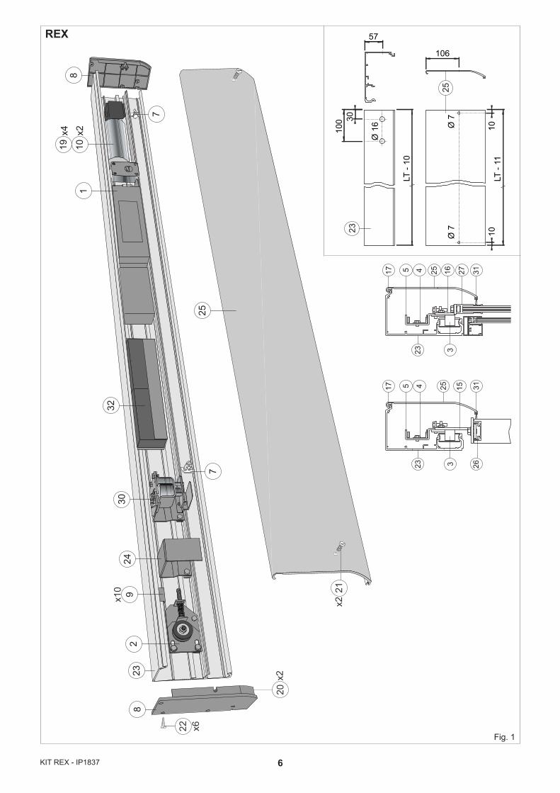
REX
LT -
11
LT -
10
57
100 30
Ø 1
6 Ø 7
Ø 7 10
10
106
23
25
22 x6
20x2
x10 21
x2
223
89
3024
25
18
1019
x2x4
7
7
32
Fig. 1
7 KIT REX - IP1837
REX-2
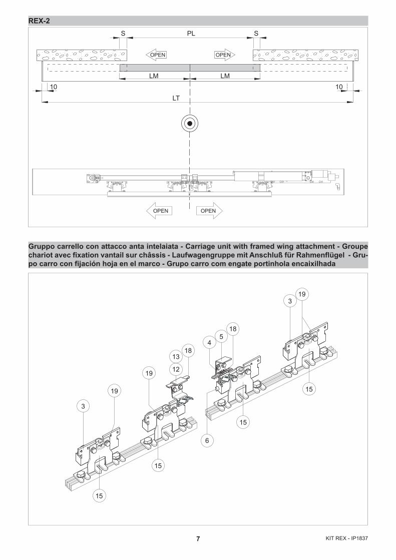
Gruppo carrello con attacco anta intelaiata - Carriage unit with framed wing attachment - Groupe chariot avec fixation vantail sur châssis - Laufwagengruppe mit Anschluß für Rahmenflügel - Gru-po carro con fijación hoja en el marco - Grupo carro com engate portinhola encaixilhada
PL
LM LM
LT
10 10
S S
OPEN OPEN
OPEN OPEN
15
15
15
15
3
6
19
19
19
18
12
13
45
3
18
8KIT REX - IP1837
REX-2
28 LB 30 3232 1 87
LT
A B
C1
C2
7
LM90 90
LM90 90
3 15 645
465
Code PL LM LT A B C1 C2 LB Note02REX2002REX2202REX2402REX2602REX2802REX3002REX3202REX3602REX4002REX4402REX4802REX5202REX5602REX6002REX66
94010401140124013401440154017401940214023402540274029403240
520570620670720770820920
1020112012201320142015201670
200022002400260028003000320036004000440048005200560060006600
260310360410460510560660760860960
1060116012601410
100150200250300350400500600700800900
100011001250
--------
50505050505050
250300350400450500550650
-------
298031803380358037803980418045804980538057806180658069807580
(4)(4)(4)(4)(4)(4)(4)(4)
(3)(4)
A=L
M-2
60
B=L
M-4
20B
≥100
LT=P
L+2L
M+2
0
LM=(
LT+2
S-20
)/4LM
=PL/
2+S
PL=(
LT-2
S-20
)/2 C2=
LT/2
-B-6
50
LB=2
(LT-
A-B
-140
)
9 KIT REX - IP1837
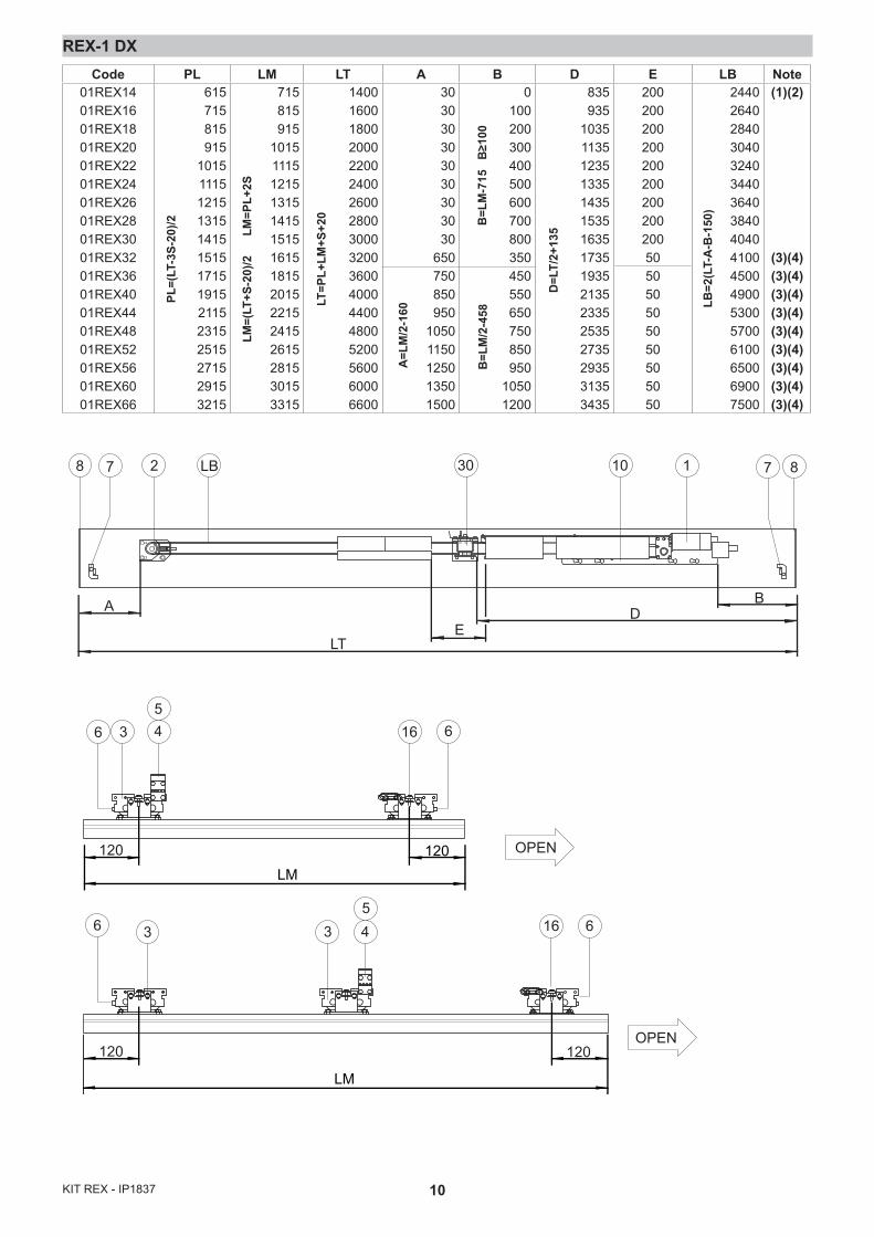
REX-1 DX
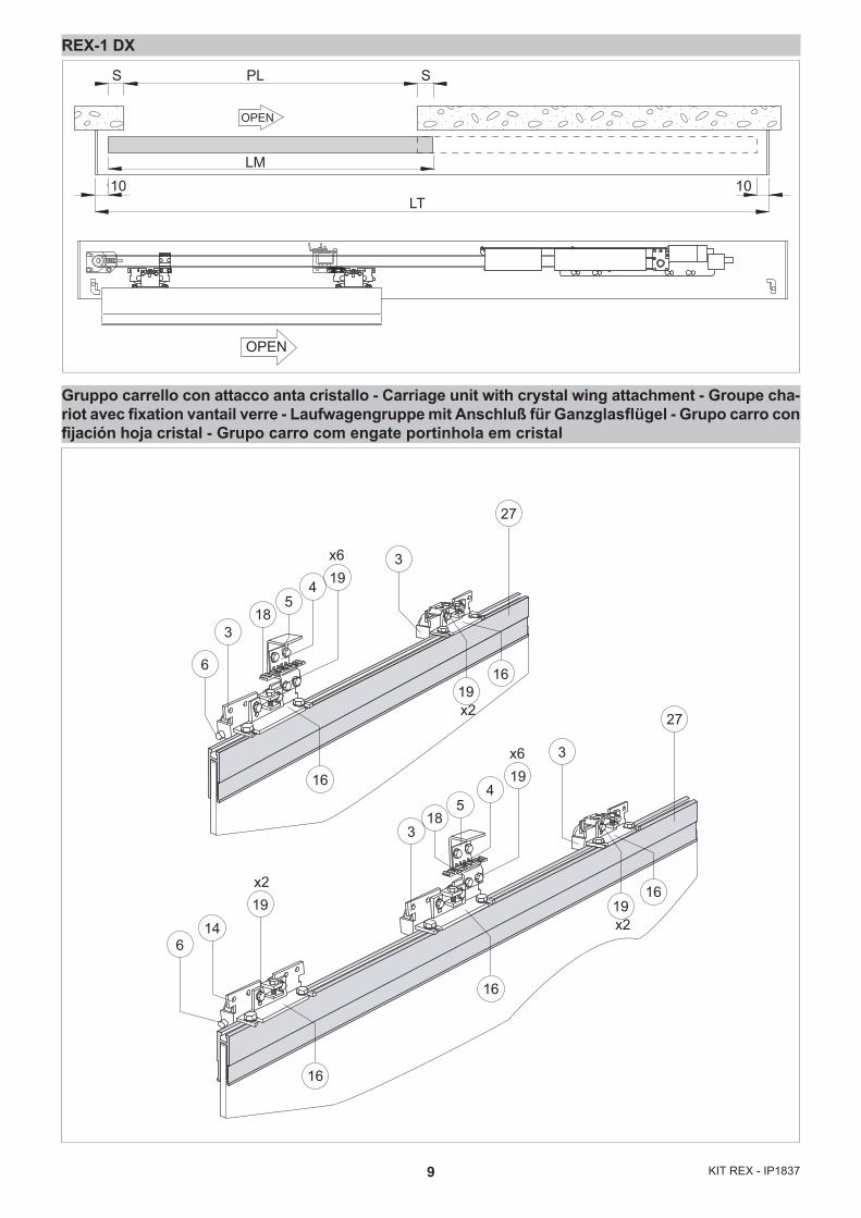
Gruppo carrello con attacco anta cristallo - Carriage unit with crystal wing attachment - Groupe cha-riot avec fixation vantail verre - Laufwagengruppe mit Anschluß für Ganzglasflügel - Grupo carro con fijación hoja cristal - Grupo carro com engate portinhola em cristal
LM
PLS S
LT10 10
OPEN
OPEN
x6
318
54 19
3
27
27
16
x2
x2
x6
614
19
318
54
193
19
16
16
16
166
x219
10KIT REX - IP1837
REX-1 DX
2 30LB8 7 87
BA
LTE
D
110
36 16 6
6
45
5
120 120LM
LM
16 633 4
120120
OPEN
OPEN
Code PL LM LT A B D E LB Note01REX1401REX1601REX1801REX2001REX2201REX2401REX2601REX2801REX3001REX3201REX3601REX4001REX4401REX4801REX5201REX5601REX6001REX66
615715815915
10151115121513151415151517151915211523152515271529153215
715815915
101511151215131514151515161518152015221524152615281530153315
140016001800200022002400260028003000320036004000440048005200560060006600
303030303030303030
650750850950
10501150125013501500
0100200300400500600700800350450550650750850950
10501200
835935
1035113512351335143515351635173519352135233525352735293531353435
200200200200200200200200200505050505050505050
244026402840304032403440364038404040410045004900530057006100650069007500
(1)(2)
(3)(4)(3)(4)(3)(4)(3)(4)(3)(4)(3)(4)(3)(4)(3)(4)(3)(4)
PL=(
LT-3
S-20
)/2
LM=(
LT+S
-20)
/2
LM
=PL+
2S
LT=P
L+LM
+S+2
0
A=L
M/2
-160
B=L
M/2
-458
B=L
M-7
15
B≥1
00
D=L
T/2+
135
LB=2
(LT-
A-B
-150
)
11 KIT REX - IP1837
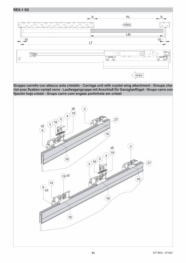
REX-1 SX
Gruppo carrello con attacco anta cristallo - Carriage unit with crystal wing attachment - Groupe cha-riot avec fixation vantail verre - Laufwagengruppe mit Anschluß für Ganzglasflügel - Grupo carro con fijación hoja cristal - Grupo carro com engate portinhola em cristal
LM
PLS S
LT10 10
OPEN
OPEN
6x2
x2
x26
14
19
318
54
3
318
54
193
16
16
16
16
27
27
x6
x619
16
12KIT REX - IP1837
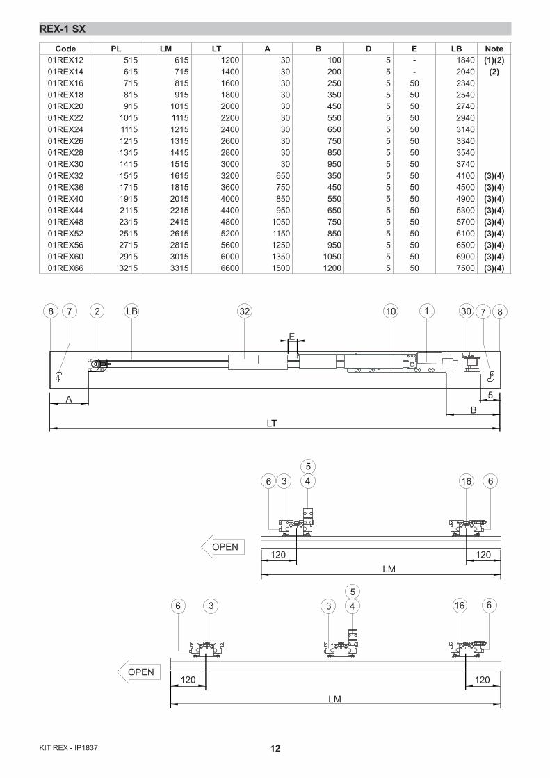
REX-1 SX
2 30LB8 7 1 8710
BA
LT
5
32
E
OPEN
OPEN
36 16 6
6
45
5
120 120LM
LM
33 4
120 120
16 6
Code PL LM LT A B D E LB Note01REX1201REX1401REX1601REX1801REX2001REX2201REX2401REX2601REX2801REX3001REX3201REX3601REX4001REX4401REX4801REX5201REX5601REX6001REX66
515615715815915
10151115121513151415151517151915211523152515271529153215
615715815915
101511151215131514151515161518152015221524152615281530153315
1200140016001800200022002400260028003000320036004000440048005200560060006600
30303030303030303030
650750850950
10501150125013501500
100200250350450550650750850950350450550650750850950
10501200
5555555555555555555
--
5050505050505050505050505050505050
1840204023402540274029403140334035403740410045004900530057006100650069007500
(1)(2)(2)
(3)(4)(3)(4)(3)(4)(3)(4)(3)(4)(3)(4)(3)(4)(3)(4)(3)(4)
13 KIT REX - IP1837
32
23
3
23
917
5
4
19
15
19
25
1
1910
23
30
16
KR
EX1N
MO
TB
L
OP
EN
RP
DIP
R1
RE
SE
T
27 9 8 3 2 1 1 0
TC
on off
3
41
2
PO
WE
R
ALA
RM
+ -+ -
~ ~24 V
BAT
EN
C
-
-+
+M
otor
L N230 V~
Tran
sf.
Fuse
F1
A
Lock
Fuse
F10A
192C
1CELA
12 V
12 V
P1
SP
P2
R1
SR
R2
1 2
Ros
so -
Red
B
ianc
o - W
hite
10
+-
COM
N.O
.N.
C.
24 V
= / 0
,3 A
(max
)
Chi
usur
a au
tom
atic
a / A
utom
atic
clo
sure
; Chi
ude
/ Clo
sing
Apr
e / O
peni
n g
Sicu
rezz
a di
inve
rsio
ne /
Rev
ersa
l saf
ety
cont
act
Sto
p
Ape
rtura
par
zial
e / P
artia
l ope
nin g
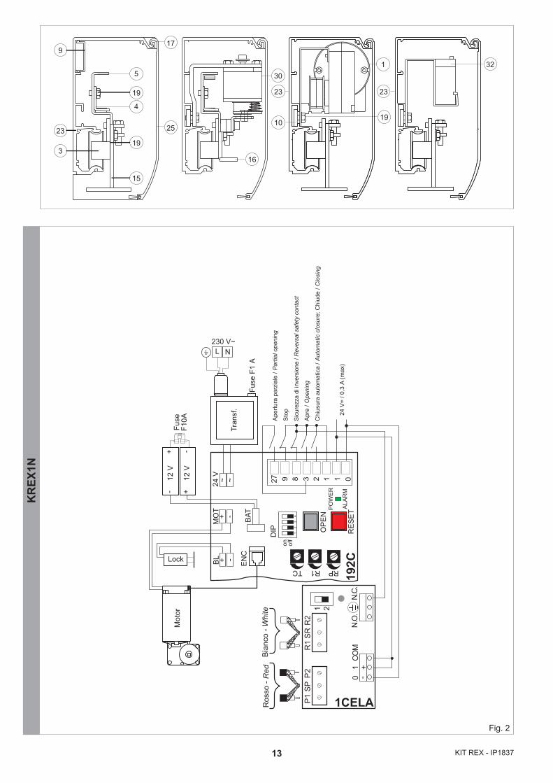
Fig. 2
14KIT REX - IP1837
Usc
ita /
Out
put 2
4 V
= / 0
,5 A
Res
etE
sclu
sion
e bl
occo
/ Lo
ck e
xclu
sion
Com
une
parz
iale
/ P
artia
l com
mon
Sto
pS
icur
ezza
in c
hius
ura
/ Clo
sing
saf
ety
Sic
urez
za in
ape
rtura
/ O
peni
ng s
afet
yC
hius
ura
/ Clo
sing
Ape
rtura
lato
B /
Ope
ning
sid
e B
Ape
rtura
lato
A /
Ope
ning
sid
e A
Chi
usur
a au
tom
atic
a / A
utom
atic
clo
sure + -
MO
T
BL
CO
M
R1
DIP
TCon of
f
POW
ERAL
ARM
SA IN
DIR
+ - + - ~ ~24
V
BA T
EN
C
-
-+
+
Mot
or
L N230 V~
Tran
sf.
F1
Lock
Fuse
F10A
EL16
J
SA
FETY
EN
AB
LEC
OM
OPEN
1A
B21
22
R E M O T E
DIR
0CEL1S
LAN4S
LAN7S
LAB9
BIXLR22
TELRS
COME
TELR
COME
TELR
Converter
DMCS
DIR
PASM24
COMH-K
DIP
RFVA
VCRP
CO
ME
TELR
J
12 V
12 V
12
272829 0123A3B4689OPEN
1G141
10
2122
on
123
KR
EX1V
Fig. 3

18KIT REX - IP1837
GB GENERAL SAFETY PRECAUTIONSThis assembling manual is intended for professionally competent personnel only.
The assembling, the electrical connections and the settings must be completed in conformity with good workmanship and with the laws in force. Read the instructions carefully before beginning assembling the product. Incorrect assembling may be a source of danger. Packaging materials (plastics, polystyrene, etc) must not be al-lowed to litter the environment and must be kept out of the reach of children for whom they may be a source of danger. Before beginning the assembling check that the product is in perfect condition.
Before connecting to the mains check that the rating is correct for the destination power requirements.
A multipolar isolation switch with minimum contact gaps of 3 mm must be included in the mains supply. Check that upstream of the electrical installation there is an adequate differential switch and a suitable circuit breaker.For repairs or replacements of products only original spare parts must be used.
It is recommended that antistatic conductive earthed arm bands be worn when manipulating electronic parts.
1. ASSEMBLING THE AUTOMATIC SYSTEM1.1 Assembling procedure- On the basis of the type of automatic system chosen,
use the sizing table (or the formulas shown) to obtain the measurements required for the assembly of the automatic system.
- Cut the aluminium of the transom box LT-10 mm and drill a hole as shown in fig. 1.
1.3 Cut the aluminium of the protective casing LT-11 mm and drill a hole as shown in fig. 1.
Note: clean the aluminium in order to remove any traces of cut material, and clean the carriage sliding tracks in particular.- Mark measurements A, B and C shown in the table (or
calculated using the formula) on the transom box with a pencil.
- Insert 2 carriages for each leaf in the guide track; if LM>1600 add another carriage per leaf (note 1).
- Make the carriages slide along the guide tracks in order to check that the wheels are not dented (and replace them if dented).
- Fasten the leaf connection brackets on the carriages (as shown in the diagrams) and fasten the belt connection and collision locking brackets to the carriages in the positions shown in the table.
- Fit the component anchorage plates [10] in the appropriate guide track of the transom box, see page 11.
- Secure the parts (without over-tightening): command and drive unit [1], belt transmission [2], block [30] and batteries [32], to the casing with the supplied screws, and follow the measurements indicated in the table.
Note: with automatic systems LT≥3200 anchor the protective casing support bracket [24].- Position the rabbet stops [7] and rabbet plugs [6] inside
the guide track.
1.2 Adjusting the belt- Loosen the screws that fasten the transmission unit to the
transom box.
- Loosen the belt connection bracket.- Cut the belt to measurement LB (see tables), thread the
belt LB between the motor pulley and the transmission unit [2] and join it in correspondence with the belt connection bracket (Note: cut off any excess length).
- Pull the entire transmission unit manually to the left and anchor it to the transom box.
- Loosen the screw until the spring is compressed to 20÷22 mm.
- Lock in place with the screws [F].- Insert the rabbet stop in the centre of the transom
box without tightening the screws. Keep the carriages resting against the rabbet stop and fasten the belt on the carriage.
Attention: a wrong adjustment can prevent the automation from working properly.- Tighten all the screws. - Anchor the heads to the transom box.
2. WIRING- Connect the command and drive unit [1] to the block [30]
and to the batteries [32] with the appropriate wires.- For the 192C electronic board version only, connect the
1CELA photocell amplifier to the electronic board (fig. 2).- Fasten the wires using the wire clips [9] supplied.
2
F
LT<2600 = 22 mm LT≥2600 = 20 mm
19 KIT REX - IP1837
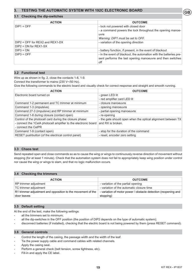
GB3. TESTING THE AUTOMATIC SYSTEM WITH 192C ELECTRONIC BOARD3.1 Checking the dip-switches
3.2 Functional testWire up as shown in fig. 2, close the contacts 1-8, 1-9. Connect the transformer to mains (230 V~/50 Hz). Give the following commands to the electric board and visually check for correct response and straight and smooth running.
3.3 Chaos testSend repeated open and close commands so as to cause the wing or wings to continuously reverse direction of movement without stopping (for at least 1 minute). Check that the automation system does not fail to appropriately keep wing position under control nor cause the wing or wings to slam, and that no logic malfunction occurs.
3.4 Checking the trimmers
3.5 Default settingAt the end of the test, make the following settings:- all the trimmers set to minimum;- all the dip-switches in the OFF position (the position of DIP2 depends on the type of automatic system);- disconnect batteries (if installed), checking that the electric board is not being powered by them (press RESET command).
3.6 General controls- Control the length of the casing, the passage width and the width of the leaf.- Tie the power supply cable and command cables with related channels.- Apply the casing seal.- Perform a general check (belt tension, screw tightness, etc). - Fill-in and apply the CE label.
ACTION OUTCOMEElectronic board turned on - green LED lit
- red amplifier card LED litCommand 1-2 permanent and TC trimmer at minimum - closure manoeuvreCommand 1-3 (impulsive) - opening manoeuvreCommand 27-3 (impulsive) and RP trimmer at minimum - partial opening manoeuvreCommand 1-8 during closure (contact open) - re-openingControl of the photocell card during the closure phase:- connect the 1CelA photocell amplifier to the electronic board - connect the CelPR
- the gate should open when the optical alignment between TX and RX is broken.
Command 1-9 (contact open) - stop for the duration of the commandRESET pushbutton (of the electrical control panel) - reset, encoder zero setting
ACTION OUTCOMEDIP1 = OFF - lock not powered with closed door
- a command powers the lock throughout the opening manoe-uvre Warning: DIP1 must be set to OFF.
DIP2 = OFF for REX2 and REX1-DXDIP2 = ON for REX1-SX
- variation of the opening direction
DIP3 = ON - battery function, if present, in the event of blackout DIP3 = OFF - in the event of blackout, the automation with the batteries pre-
sent performs the last opening manoeuvre and then switches off
ACTION OUTCOMERP trimmer adjustment - variation of the partial openingTC trimmer adjustment - variation of the automatic closure timeR1 trimmer adjustment and opposition to the movement of the door leaves
- variation of motor power / obstacle detection (reopening and stopping)
20KIT REX - IP1837
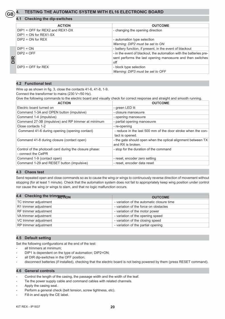
GB 4. TESTING THE AUTOMATIC SYSTEM WITH EL16 ELECTRONIC BOARD4.1 Checking the dip-switches
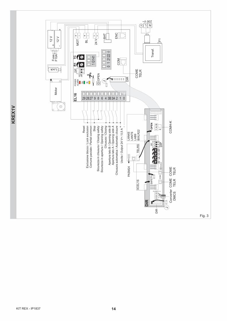
4.2 Functional testWire up as shown in fig. 3, close the contacts 41-6, 41-8, 1-9. Connect the transformer to mains (230 V~/50 Hz). Give the following commands to the electric board and visually check for correct response and straight and smooth running.
ACTION OUTCOMEElectric board turned on - green LED litCommand 1-3A and OPEN button (impulsive) - closure manoeuvreCommand 1-4 (impulsive) - opening manoeuvreCommand 27-3B (impulsive) and RP trimmer at minimum - partial opening manoeuvreClose contacts 1-2 - re-openingCommand 41-6 during opening (opening contact) - reduce in the last 500 mm of the door stroke when the con-
tact is opened.Command 41-8 during closure (contact open) - the gate should open when the optical alignment between TX
and RX is broken.Control of the photocell card during the closure phase:- connect the CelPR
- stop for the duration of the command
Command 1-9 (contact open) - reset, encoder zero settingCommand 1-29 and RESET button (impulsive) - reset, encoder data reset
4.3 Chaos testSend repeated open and close commands so as to cause the wing or wings to continuously reverse direction of movement without stopping (for at least 1 minute). Check that the automation system does not fail to appropriately keep wing position under control nor cause the wing or wings to slam, and that no logic malfunction occurs.
4.4 Checking the trimmers
4.5 Default settingSet the following configurations at the end of the test:- all trimmers at minimum;- DIP1 is dependent on the type of automation; DIP2=ON;- all DIR dip-switches in the OFF position;- disconnect batteries (if installed), checking that the electric board is not being powered by them (press RESET command).
4.6 General controls- Control the length of the casing, the passage width and the width of the leaf.- Tie the power supply cable and command cables with related channels.- Apply the casing seal.- Perform a general check (belt tension, screw tightness, etc). - Fill-in and apply the CE label.
ACTION OUTCOMEDIP1 = OFF for REX2 and REX1-DXDIP1 = ON for REX1-SX
- changing the opening direction
DIP2 = ON for REX - automation type selectionWarning: DIP2 must be set to ON
DIP1 = ON - battery function, if present, in the event of blackoutDIP2 = OFF - in the event of blackout, the automation with the batteries pre-
sent performs the last opening manoeuvre and then switches off
DIP3 = OFF for REX - block type selection Warning: DIP3 must be set to OFF
DIR
ACTION OUTCOMETC trimmer adjustment - variation of the automatic closure timeR1 trimmer adjustment - variation of the force on obstacles RF trimmer adjustment - variation of the motor powerVA trimmer adjustment - variation of the opening speed VC trimmer adjustment - variation of the closing speed RP trimmer adjustment - variation of the partial opening