Embed Size (px)
Citation preview
→ LNG import terminals
Gateways to clean energy.
LNG import terminals.
02 Contents
Contents.
03 Introduction
04 Main installations and design features
05 Safety and quality
06 Jetty installations
07 Product storage
Tank types and integrity levelsMid- to large-scale storage tanks with full integrity level
10 Product processing and distribution
Boil-off gas handlingRegasification and send-outTruck, railcar and container loadingShip bunkering
14 Core cryogenic equipment
Vacuum-insulated pipingRecondensersCentrifugal and reciprocating pumpsSubmerged pumpsStandard tanksHeat exchangersAir-heated vaporisersWater-bath vaporisersSubmerged combustion vaporisers
19 Engineering, procurement and construction
21 Operation and maintenance
22 References
03Introduction
Introduction.
LNG (Liquefied Natural Gas) is becoming the preferred method of trans-port and storage of natural gas. In the LNG value chain, LNG-receiving terminals play an important role, allowing for the sourcing of LNG from all over the world and creating a new dynamic in the local natural gas market. Installations for the export of the natural gas from the receiv-ing terminal to the various consumers – either in liquid or gaseous form – provide the required flexibility to match the market demand.
With more than 125 years of comprehensive experience in the handling of cryogenic liquids, Linde Engineering has a track record in the design and performance of a wide range of natural gas projects, including both LNG import and export terminals.
Furthermore, Linde Engineering is well recognised as a reliable tech-nology provider and EPC contractor, both by its customers and the financial world.
Own manufacturing capabilities for core cryogenic equipment, such as vaporisers, pumps, expanders and vacuum-insulated piping, comple-ment Linde Engineering’s unique profile and enable it to customise the process design and core equipment while implementing a project man-agement approach that eliminates complex interfaces and delivers a product with optimised performance.
Mainly, three factors determine the storage capacity and thus the scale of an LNG-receiving terminal: quantity and frequency of product deliv-ery by LNG carrier, holding time, and captive and expected demand.
World-scale receiving terminals usually have a storage capacity of more than 100,000 m³ of LNG, serving as main hubs for the LNG supply to national gas grids and allowing for the further distribution of LNG to small- or mid-scale terminals. These terminals are located at major ports with drafts of over 15 metres, which allows the safe manoeuvring and berthing of LNG carriers with a capacity of up to 200,000 m³.
Mid-scale terminals, ranging from 10,000 m³ to 100,000 m³ in storage capacity, play a decisive role in the LNG supply chain and meet the nat-ural gas demand of a variety of customers – from commercial users, e.g. petrochemical and marine industries, to residential users, e.g. private households, which are all served by local gas grids.
Small-scale terminals and satellite stations mainly supply natural gas directly to consumers with high local demand and thus may not nec-essarily be located at a harbour or an extensive gas grid. The LNG is either stored in flat-bottom tanks with a storage capacity of up to 10,000 m³ or in cryogenic standard tanks with a single storage tank capacity of up to 1,000 m³ each. The storage capacity and number of installed standard tanks are designed to achieve an optimised econom-ical and technical solution. The vacuum insulation of the standard tanks ensures a long holding time with a very low boil-off gas rate.
OPTISIM® and Sub-X® are registered trademarks of The Linde Group.

(Un)loading facility
LNG storage tank
Vapour return line
(Un)loading line
BOG line
Merchant LNG
Sales gas LP pipeline
Sales gasHP pipeline
Sub cooler
BOGcompressor
Buffer tank VaporiserLNG booster pump Metering station
Metering station
Truck, railcar and container loading
Vaporiser
Recondensation
Flare
04 Main installations and design features
Main installations and design features.
Onshore LNG import terminals basically consist of a jetty with respec-tive receiving facilities, product storage and processing installations, and distribution facilities for the export of the natural gas to the vari-ous customers, either in liquid or gaseous form.
The jetty is, so to speak, the LNG terminal’s gate to the market. It ensures a safe berthing of the LNG carrier and an efficient unloading of the product via loading arms using the LNG carrier’s export pumps. Vacuum-insulated piping is used to transfer the LNG from the jetty to the storage tanks.
For LNG storage, different tank designs are available, which are described in more detail on the following pages. In general, LNG is stored under atmospheric pressure at a temperature of around -162 °C. The capacity of the storage facilities is designed to allow users to cope with the fluctuating consumer demand to a certain extent. The con-tinuous boil-off gas stream is processed accordingly, depending on the availability of natural gas consumers.
For distribution, the LNG is transferred by submerged LNG pumps installed in the LNG storage tanks either to regasification or loading facilities. In case of regasification, different types of vaporisers are used for evaporating the LNG and sending the natural gas to the sales gas grid. The loading facilities might comprise installations for truck, railcar or container loading as well as possibilities for barge loading or ship bunkering.
One key element in the design of LNG import terminals is a well-thought-out management of the continuous boil-off and intermittent return gas streams. This ensures an economic operation of the plant and thus contributes to providing competitive pricing in the local natu-ral gas market. In addition, Linde Engineering’s profound know-how and vast experience in the design of cryogenic processes and equip-ment as well as its manufacturing capabilities allow it to both custom-ise and optimise the complex LNG terminal design.
The detailed installations of an onshore LNG import terminal and the complexity of the arrangement mainly depend on the required boil-off gas handling and distribution facilities for the export of the natural gas. This is depicted in the block diagram below.
Block diagram: Onshore LNG import terminal

05Safety and quality
Safety and quality.
The safe and reliable operation of all LNG terminal installations is a decisive design element – from the early planning stages to project implementation and throughout the lifetime of the plant. Therefore, safety measures are adhered to and several hazard and risk assess-ments are carried out in order to ensure acceptable risk levels:
→ All relevant safety rules, codes, standards and practices are followed, e.g. EN 1473, EN 14620 and IEC 61511.
→ Detailed P&IDs showing all process-relevant safety measures are validated in multidisciplinary HAZOP (hazard and operability) stud-ies to verify that all possible hazards are adequately addressed.
→ An SIL allocation study according to IEC 61511 assesses all rele-vant risks covered by safety instrumented systems by using a risk matrix with risk parameters such as frequency, consequence and independent protection layers.
→ The plant layout is validated in a plant layout study, HAZID (haz-ard identification) study and/or QRA (quantitative risk assess-ment), verifying all relevant safety distances to critical equipment, surrounding property and public areas.
→ Hazardous areas are classified and preventive measures to avoid explosions, e.g. the installation of a gas detection system, are defined.
→ Measures for environmental protection, including emission control, noise control, effluent and waste control, are taken.
At Linde Engineering, process and occupational safety, health, environment and quality (SHEQ) always have top priority throughout all project phases, i.e. engineering, procurement, construction, start-up and operation.
SHEQ influences100 % of our behaviour,100 % of the time!
Resulting from the various assessments, the safety systems of an onshore LNG import terminal typically comprise:
→ Flare → Fire and gas detection → Safety valves, safety instrumented system (SIS) and ESD → Firefighting including hydrants, monitors, extinguishers,
dry powder units etc. → Passive fire protection → Impoundment and spill protection with drainage channels,
pits and sump pumps
To ensure that standards as well as authority and project requirements with regard to process and occupational safety, health, environmental protection and quality are met, Linde Engineering has implemented an integrated management system (IMS), which is followed throughout all phases of a project.
The following guidelines and specifications are implemented in the IMS: → Applicable statutory provisions → Applicable guidelines of Linde Engineering and The Linde Group → Linde Engineering SHEQ policy → DIN EN ISO 9001:2008 → OHSAS 18001:2007 → Pressure Equipment Directive (PED) 97/23/EG → DIN EN ISO 14001:2005

06 Jetty installations
Jetty installations.
The marine installations of an LNG import terminal comprise the jetty equipped with a quick-release mooring system and marine loading arms, allowing for the safe berthing of vessels and transfer of LNG dur-ing unloading, loading or bunkering operations.
The marine loading arms are especially designed to cope with the cry-ogenic temperatures and are equipped with various features to allow for the safe transfer of the LNG, e.g. couplings for quick connect/dis-connect operations. The size of the loading arms is mainly defined by the unloading/loading rates as well as the operating range of the ves-sels berthing at the jetty.
Insulated pipelines covering the often rather long distance between the jetty and the LNG storage tank are used for the product transfer. An emergency shut-down (ESD) system, which is activated locally or remotely, ensures the safe and reliable stop of all LNG transfer activi-ties and blocking of critical process units.
In such a case, the transfer of the cryogenic fluid in the long piping involves the potential risk of hydraulic pressure surge (HPS). Linde Engineering provides a full-service analysis of this scenario as part of one of its key areas of expertise in the design of LNG terminals. The HPS analysis covers the critical piping and the results are translated directly into the layout and the pipe routing to ensure a safe plant operation. Using the characteristic method, the analysis also cov-ers steady-state and transient flow conditions. In addition to a surge analysis including cavity effects, typical applications are:
→ Simulation of meshed piping systems → Calculation of plant characteristics → Investigation of the filling sequence of empty (dry) piping systems
LNG loading arms, Nynäshamn LNG terminal, Sweden

07Product storage
Product storage.The storage of the LNG has a great impact on the capital and opera-tional expenditures of an import terminal. There is a variety of storage solutions and Linde Engineering is one of few companies that can pro-vide the process design for an LNG terminal and offer all LNG storage tank types and technologies applied in the industry today.
Safety aspects, the required storage capacity as well as the pressure-related boil-off and ship return gas management have to be taken into account for the selection of the appropriate storage tank type and technology.
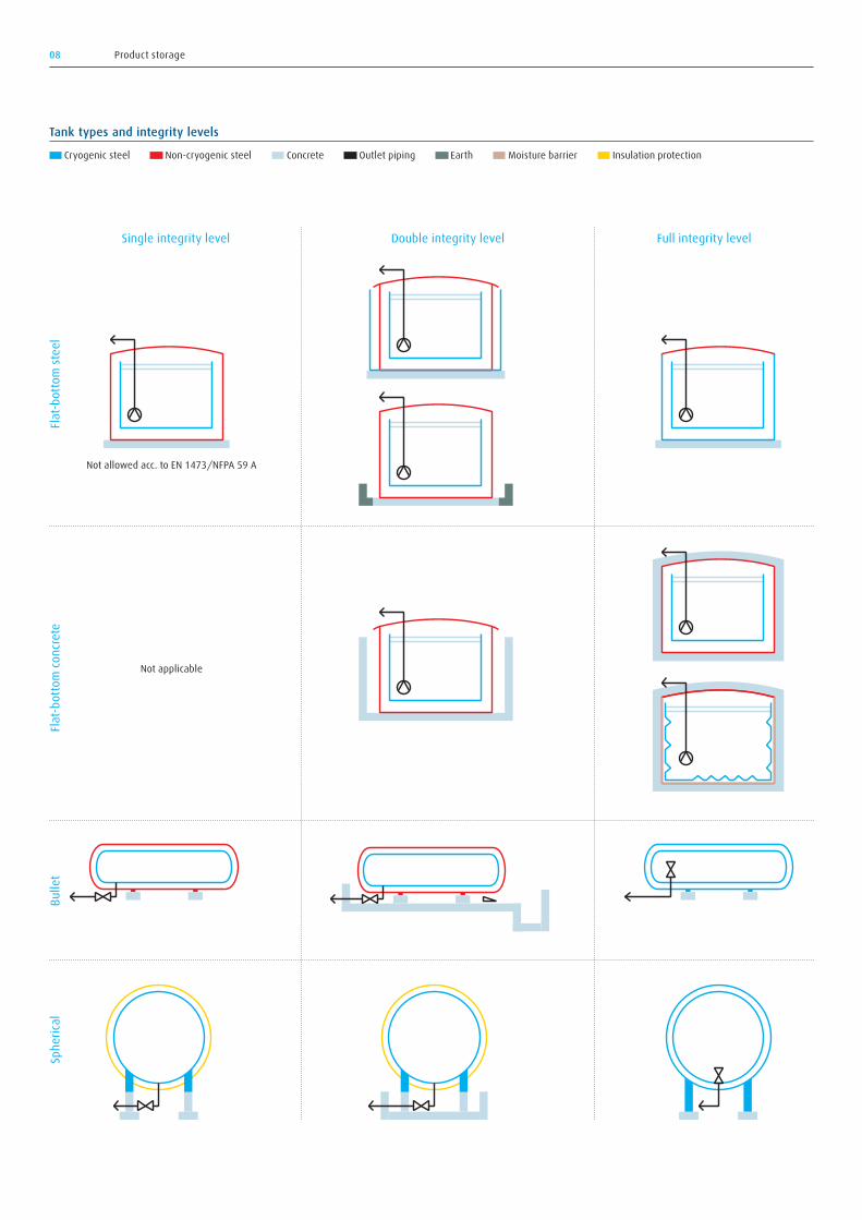
Depending on the storage capacity and operating pressure, the follow-ing three tank types are generally available:
→ Flat-bottom tank: 2,000–250,000 m³ (today, even larger capacities seem feasible)
→ Spherical tank: 1,000–8,000 m³ → Bullet tank: 100–1,000 m³
Flat-bottom storage tanks are operated at atmospheric pressure, whereas spherical and bullet tanks allow for pressurised operation.
In consideration of the cryogenic nature of LNG and the amount of energy contained in relation to the volume, a high priority is given to safety aspects when it comes to the handling and storage of LNG. In the unlikely event of a failure, i.e. when the secondary contain-ment is in direct contact with the LNG, the following scenarios, which
correspond to the integrity level of the installation, have to be evalu-ated. The integrity level itself depends on the storage tank type and the specific technology and materials used in its design (see overview on the following page).
Single integrity level tankUncontrolled spill of LNG into the environment followed by uncon-trolled vapour release to the atmosphere
Double integrity level tankLNG spill into the secondary containment (dike, pit) followed by uncon-trolled vapour release to the atmosphere
Full integrity level tankNo LNG spill into the environment and only controlled vapour release to the atmosphere
As a result of the safety approach and efforts taken by the industry, LNG storage tanks with medium and large capacities as well as double or full integrity levels inherent to the design have become the stand-ard. Today, single level integrity tanks are typically only accepted for very small storage volumes. EN 13645, for example, applies to capaci-ties of up to 200 metric tons of LNG – an understandable limit consid-ering the major hazard potential represented by its energy equivalent (10 TJ). Thus, single level integrity tanks are mainly only acceptable in remote areas, where they do not expose any population or critical infrastructure to the inherent risk.
Example 1: LNG storage tank in Bergen Example 2: LNG storage tank in Stavanger Example 3: LNG storage tank in Kwinana → Flat bottom, steel/steel, full containment → Working volume: 2,000 m³ → Operating pressure: atmospheric
→ Flat bottom, concrete/steel, full containment
→ Working volume: 30,000 m³ → Operating pressure: atmospheric
→ Spherical, double integrity → Working volume: 4,000 m³ → Operating pressure: 3.5 bar abs
08 Product storage
Tank types and integrity levels Cryogenic steel Non-cryogenic steel Concrete Outlet piping Earth Moisture barrier Insulation protection
Single integrity level
Not applicable
Not allowed acc. to EN 1473/NFPA 59 A
Flat-b
otto
m ste
elFla
t-bot
tom
conc
rete
Bulle
tSp
heric
al
Double integrity level Full integrity level
09Product storage
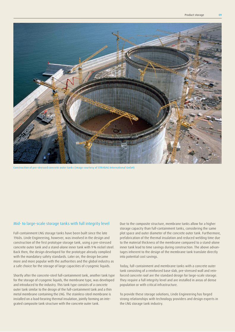
Construction of pre-stressed concrete outer tanks (image courtesy of STRABAG International GmbH)
Mid- to large-scale storage tanks with full integrity level
Full-containment LNG storage tanks have been built since the late 1960s. Linde Engineering, however, was involved in the design and construction of the first prototype storage tank, using a pre-stressed concrete outer tank and a stand-alone inner tank with 9 % nickel steel. Back then, the design developed for the prototype already complied with the mandatory safety standards. Later on, the design became more and more popular with the authorities and the global industry as a safe choice for the storage of large capacities of cryogenic liquids.
Shortly after the concrete-steel full-containment tank, another tank type for the storage of cryogenic liquids, the membrane type, was developed and introduced to the industry. This tank type consists of a concrete outer tank similar to the design of the full-containment tank and a thin metal membrane containing the LNG. The stainless-steel membrane is installed on a load-bearing thermal insulation, jointly forming an inte-grated composite tank structure with the concrete outer tank.
Due to the composite structure, membrane tanks allow for a higher storage capacity than full-containment tanks, considering the same plot space and outer diameter of the concrete outer tank. Furthermore, prefabrication of the thermal insulation and reduced welding time due to the material thickness of the membrane compared to a stand-alone inner tank lead to time savings during construction. The above advan-tages inherent to the design of the membrane tank translate directly into potential cost savings.
Today, full-containment and membrane tanks with a concrete outer tank consisting of a reinforced base slab, pre-stressed wall and rein-forced concrete roof are the standard design for large-scale storage. They require a full integrity level and are installed in areas of dense population or with critical infrastructure.
To provide these storage solutions, Linde Engineering has forged strong relationships with technology providers and design experts in the LNG storage tank industry.

10 Product processing and distribution
Product processing and distribution.
Submerged combustion vaporisers
Various installations are required for the processing and distribution of the liquid and gaseous products of the LNG terminal. The main process-ing steps are the boil-off gas handling as well as the vaporisation and tempering of the natural gas.
In case the LNG is stored in flat-bottom tanks under atmospheric pres-sure, the transfer and distribution of the liquid product to the different loading and send-out facilities is performed by low-pressure pumps
installed in the tank. Boosting services required for a high-pressure send-out are realised by vessel-mounted suction pumps installed outside of the LNG storage tank.
For the commercial operation of the LNG terminal, metering systems or weighbridges are installed to record the product unloading, loading and send-out.

11Product processing and distribution
Boil-off gas handling
Boil-off gas generated through heat ingress as well as intermittent gas from the product unloading and loading operations require continuous removal from the LNG storage tank. There are various possibilities to handle this gas volume, which is generated on a rather transient basis, ranging from a temporary pressure increase in the LNG storage tank to the send-out to a low-pressure pipeline or to the installation of recon-densation and even liquefaction facilities.
The system design for the handling of the generated gas is mainly influenced by the storage tank capacity, the degree of insulation, the operating pressure, the imported LNG product properties, the expected operating scenario of the terminal’s loading and send-out facilities as well as the possibility of continuous consumption of the gas.
The customisation of the boil-off gas handling system and also the optimisation of the capital and operational expenditures for the overall LNG terminal are facilitated by Linde Engineering’s profound cryogenic process design know-how, its own property databases and its simula-tion tool OPTISIM®.
Regasification and send-out
The regasification of the liquefied natural gas before its send-out to a low- or high-pressure pipeline can be performed by various types of equipment, including air-heated vaporisers, submerged combustion vaporisers (SCV), open rack vaporisers (ORV) operating with sea water, or shell-tube heat exchangers using various heating media, e.g. district heat, glycol/water or hot oil.
For the selection of the vaporisation equipment, the following criteria apply:
→ Capacity → Available plot area → Availability of heating media or sea water (ORV) → Environmental aspects (air and water emissions) → Capital, heat or fuel cost
12 Product processing and distribution
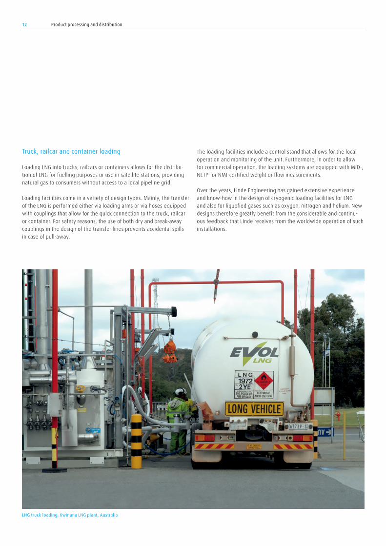
Truck, railcar and container loading
Loading LNG into trucks, railcars or containers allows for the distribu-tion of LNG for fuelling purposes or use in satellite stations, providing natural gas to consumers without access to a local pipeline grid.
Loading facilities come in a variety of design types. Mainly, the transfer of the LNG is performed either via loading arms or via hoses equipped with couplings that allow for the quick connection to the truck, railcar or container. For safety reasons, the use of both dry and break-away couplings in the design of the transfer lines prevents accidental spills in case of pull-away.
The loading facilities include a control stand that allows for the local operation and monitoring of the unit. Furthermore, in order to allow for commercial operation, the loading systems are equipped with MID-, NETP- or NMI-certified weight or flow measurements.
Over the years, Linde Engineering has gained extensive experience and know-how in the design of cryogenic loading facilities for LNG and also for liquefied gases such as oxygen, nitrogen and helium. New designs therefore greatly benefit from the considerable and continu-ous feedback that Linde receives from the worldwide operation of such installations.
LNG truck loading, Kwinana LNG plant, Australia
Vacuum-insulated storage tank
Pump
Alternative boil-off gas managementSub cooler
(Un)loading facility(Un)loading line
Block diagram: Bunkering
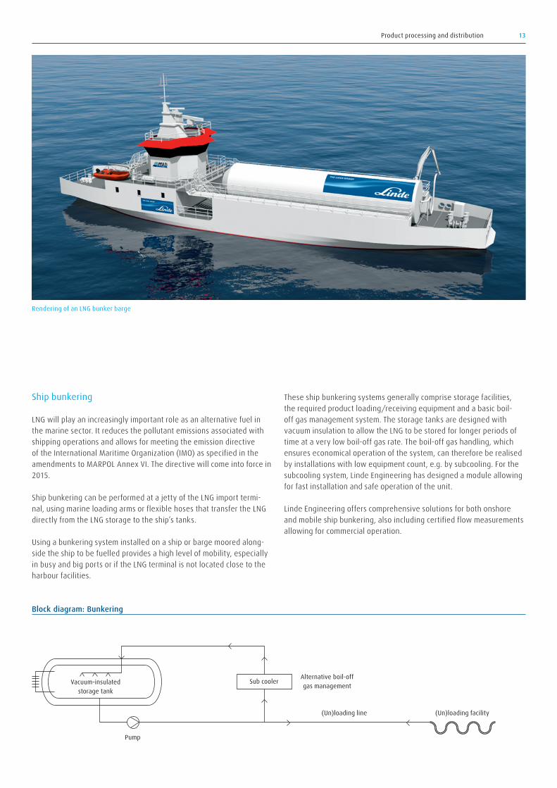
Rendering of an LNG bunker barge
Product processing and distribution 13
Ship bunkering
LNG will play an increasingly important role as an alternative fuel in the marine sector. It reduces the pollutant emissions associated with shipping operations and allows for meeting the emission directive of the International Maritime Organization (IMO) as specified in the amendments to MARPOL Annex VI. The directive will come into force in 2015.
Ship bunkering can be performed at a jetty of the LNG import termi-nal, using marine loading arms or flexible hoses that transfer the LNG directly from the LNG storage to the ship’s tanks.
Using a bunkering system installed on a ship or barge moored along-side the ship to be fuelled provides a high level of mobility, especially in busy and big ports or if the LNG terminal is not located close to the harbour facilities.
These ship bunkering systems generally comprise storage facilities, the required product loading/receiving equipment and a basic boil-off gas management system. The storage tanks are designed with vacuum insulation to allow the LNG to be stored for longer periods of time at a very low boil-off gas rate. The boil-off gas handling, which ensures economical operation of the system, can therefore be realised by installations with low equipment count, e.g. by subcooling. For the subcooling system, Linde Engineering has designed a module allowing for fast installation and safe operation of the unit.
Linde Engineering offers comprehensive solutions for both onshore and mobile ship bunkering, also including certified flow measurements allowing for commercial operation.
14 Core cryogenic equipment
Core cryogenic equipment.In addition to its role as a technology provider and EPC contractor, Linde Engineering also designs and manufactures a large part of the core cryogenic equipment installed in onshore LNG import terminals and along the LNG value chain. The equipment can either be customised or provided in a standard configuration.
Vacuum-insulated piping
Linde and PHPK Technologies have teamed up to provide vacuum-insu-lated piping of superior quality for application in LNG terminals, lique-faction plants and peak-shaving facilities.
The piping is available for a wide range of sizes and pressures as well as different materials. Depending on the installation conditions, the system design incorporates either internal or external expansion joints. The vacuum-insulation system features laminated radiation shielding and a low-conductive spacer material allowing for less than 10 % of the steady-state heat gain of mechanically insulated piping systems.
In short, Linde’s vacuum-insulated piping offers the following benefits: → Reduction of boil-off gas → Lower maintenance costs → Reduced installation costs → Longer prefabricated sections with fewer joints
In addition, double-wall vacuum-insulated piping can be designed and manufactured to act as containment piping.
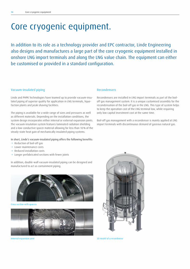
Recondensers
Recondensers are installed in LNG import terminals as part of the boil-off gas management system. It is a unique customised assembly for the recondensation of the boil-off gas in the LNG. This type of system helps to keep the operation cost of the LNG terminal low, while requiring only low capital investment cost at the same time.
Boil-off gas management with a recondenser is mainly applied at LNG import terminals with discontinuous demand of gaseous natural gas.
3D model of a recondenser
Cross section with spacers
Internal expansion joint

15Core cryogenic equipment
Centrifugal and reciprocating pumps
Stationary centrifugal pumps are used to transfer LNG between pressurised storage tanks and road tankers. Furthermore, they are installed in vehicle refuelling units and can also be applied in ship bunkering systems.
Generally, these pumps fill low-, medium- or high-pressure tanks at a high flow rate of up to 500 m³/h. Skid-mounted systems including a control panel for local operation are available in case a turnkey transfer system for LNG is required.
Reciprocating pumps can be used for applications such as LCNG refu-elling stations, CH4 cylinder filling stations, peak-shaving applications and customised high-pressure applications.
Depending on the country for which the equipment is provided, the pumps are supplied with all safety devices according to ATEX or IECEx requirements.
Submerged pumps
Low-pressure vertical submerged motor pumps with a horizontal impel-ler design are installed in pump wells in the LNG storage tank or exter-nally within a sump. These pumps are used to transfer the product to the various loading and send-out facilities of the terminal or for recir-culation of the LNG in the storage tank to avoid stratification and pos-sible roll-over.
High-pressure continuous-crossover pumps installed in suction vessels or pots are used for boosting services to allow for the high-pressure send-out of the vaporised natural gas.
Centrifugal pump
Reciprocating pump Disassembled submerged pump, SUBTRAN
16 Core cryogenic equipment
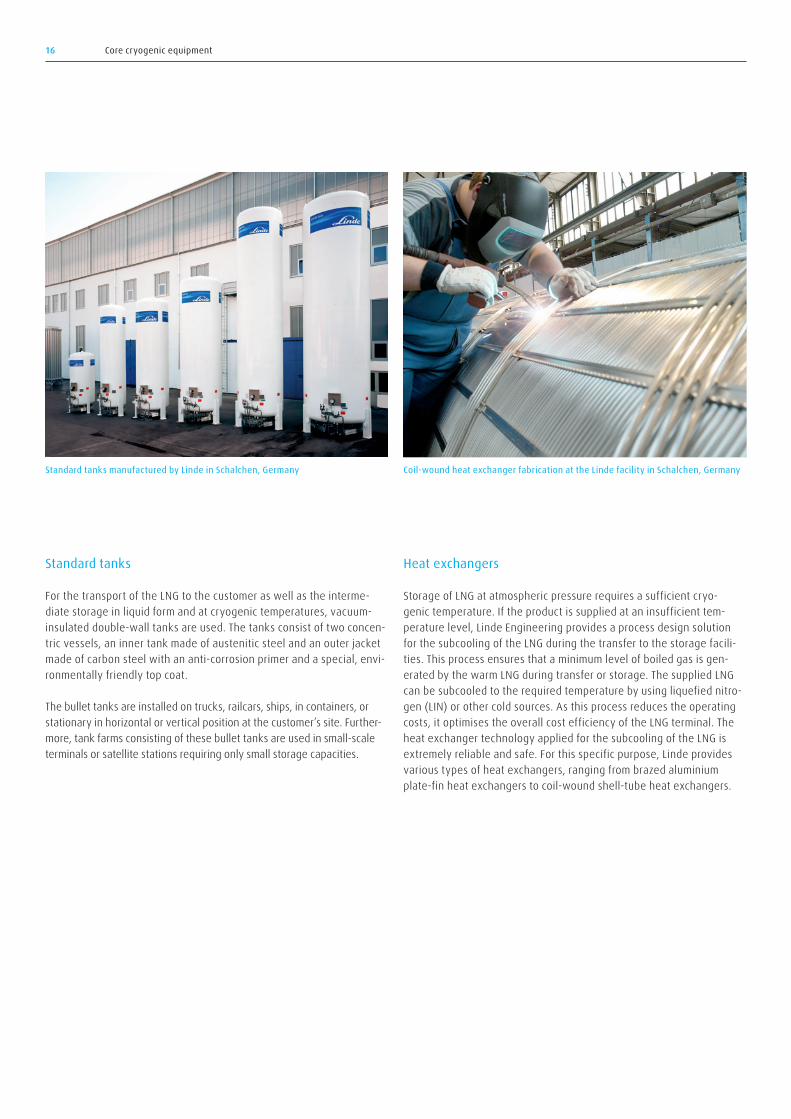
Standard tanks
For the transport of the LNG to the customer as well as the interme-diate storage in liquid form and at cryogenic temperatures, vacuum-insulated double-wall tanks are used. The tanks consist of two concen-tric vessels, an inner tank made of austenitic steel and an outer jacket made of carbon steel with an anti-corrosion primer and a special, envi-ronmentally friendly top coat.
The bullet tanks are installed on trucks, railcars, ships, in containers, or stationary in horizontal or vertical position at the customer’s site. Further-more, tank farms consisting of these bullet tanks are used in small-scale terminals or satellite stations requiring only small storage capacities.
Heat exchangers
Storage of LNG at atmospheric pressure requires a sufficient cryo-genic temperature. If the product is supplied at an insufficient tem-perature level, Linde Engineering provides a process design solution for the subcooling of the LNG during the transfer to the storage facili-ties. This process ensures that a minimum level of boiled gas is gen-erated by the warm LNG during transfer or storage. The supplied LNG can be subcooled to the required temperature by using liquefied nitro-gen (LIN) or other cold sources. As this process reduces the operating costs, it optimises the overall cost efficiency of the LNG terminal. The heat exchanger technology applied for the subcooling of the LNG is extremely reliable and safe. For this specific purpose, Linde provides various types of heat exchangers, ranging from brazed aluminium plate-fin heat exchangers to coil-wound shell-tube heat exchangers.
Coil-wound heat exchanger fabrication at the Linde facility in Schalchen, GermanyStandard tanks manufactured by Linde in Schalchen, Germany

17Core cryogenic equipment
Air-heated vaporisers
Linde’s air-heated vaporisers are used for evaporating and super-heat-ing LNG. A new generation of all-aluminium vaporisers ensures maxi-mum air circulation due to optimised fin and vaporiser geometrics. The air-heated vaporisers are designed for a working pressure of 400 bar and an allowable operating temperature range from +50 to -196 °C.
Water-bath vaporisers
Water-bath vaporisers consist of a water-filled vessel with a submerged coil-wound tube bundle in it and are optimised to withstand quick start-ups and temperature changes. The water bath itself is heated by direct steam injection or by hot water circulation. Compared to the Linde air-heated vaporiser, this heat exchanger type, which is also manufactured by Linde, is the efficient alternative for larger vaporisa-tion capacities.
Air-heated vaporisers 3D model of a water-bath vaporiser
18 Core cryogenic equipment
Combustion air
Water tank
Coolingwater jacket
Combustion air
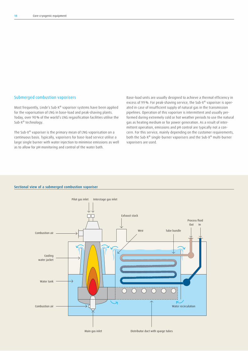
Sectional view of a submerged combustion vaporiser
Pilot gas inlet Interstage gas inlet
Exhaust stackProcess fluid
Water recirculation
Distributor duct with sparge tubesMain gas inlet
Out In
Weir Tube bundle
Submerged combustion vaporisers
Most frequently, Linde’s Sub-X® vaporiser systems have been applied for the vaporisation of LNG in base-load and peak-shaving plants. Today, over 90 % of the world’s LNG regasification facilities utilise the Sub-X® technology.
The Sub-X® vaporiser is the primary mean of LNG vaporisation on a continuous basis. Typically, vaporisers for base-load service utilise a large single burner with water injection to minimise emissions as well as to allow for pH monitoring and control of the water bath.
Base-load units are usually designed to achieve a thermal efficiency in excess of 99 %. For peak-shaving service, the Sub-X® vaporiser is oper-ated in case of insufficient supply of natural gas in the transmission pipelines. Operation of this vaporiser is intermittent and usually per-formed during extremely cold or hot weather periods to use the natural gas as heating medium or for power generation. As a result of inter-mittent operation, emissions and pH control are typically not a con-cern. For this service, mainly depending on the customer requirements, both the Sub-X® single-burner vaporisers and the Sub-X® multi-burner vaporisers are used.
19Engineering, procurement and construction
Engineering
The process engineering for an onshore LNG import terminal requires know-how and experience in the design of cryogenic processes. To tackle the rather complex design challenges regarding the equipment installations, which are determined in the light of the specified capaci-ties for unloading, loading and send-out, process design plays a deci-sive role in the engineering of an LNG terminal.
Linde Engineering’s own powerful process simulation tool OPTISIM®, its unique in-house gas property database as well as its experience and know-how gained through its own cryogenic equipment design and manufacturing capabilities support the crucial customisation and opti-misation activities during the design of an LNG terminal.
Furthermore, Linde Engineering can rely upon its own in-house engi-neering resources, ranging from the architectural and civil to the electrical and instrumentation disciplines, and can therefore offer all services required to deliver a complete and well-thought-out design, while minimising costly and time-consuming interfaces at the same time.
Procurement
Linde Engineering’s global procurement organisation is set up to face the challenges of an ever-changing global supplier market and to source equipment and materials in time, at reasonable cost and within the specified quality.
With procurement centres located in Europe, North America, Asia and the Middle East, the organisation is well positioned, close to local sup-pliers and the markets served.
Expediting and logistic operations form an integral part of the organi-sation and allow for close cooperation with customers. Beginning with the inquiry and order placement, through to inspection, testing and successful delivery of the equipment and material to the fabrication yards and/or the construction site, Linde Engineering’s procurement organisation is constantly monitoring the entire procurement process to ensure a smooth integration into the LNG terminal.
Engineering, procurement and construction.
Linde Engineering is known in the industry as a reliable contractor and has a worldwide track record of successfully delivering EPC projects.
Its engineering and procurement centres are located throughout Europe, North America, Asia and the Middle East, thus being close to its customers and the markets served. During all phases of a project and specifically during construction, Linde Engineering typically cooperates with local partners, which is considered as a key factor for its success.

20 Engineering, procurement and construction
Construction
Linde Engineering is experienced in construction and uses both “stick-built” and modularised concepts. For an onshore LNG import termi-nal, the standard approach is a “stick-built” concept, considering that a flat-bottom atmospheric storage tank solution is always the critical item regarding the overall project duration. The storage tank construc-tion only accommodates a low degree of off- and on-site prefabrication and thus modularising the other required LNG terminal installations has to be carefully evaluated and adjusted by considering site-specific and overall economic conditions of the project. Premium engineer-ing, structural and transportation costs required by a high degree of prefabrication or even modularisation are to be put in perspective to the site’s climatic conditions and available labour qualifications, which both influence the efficiency.
A modularisation concept reduces on-site construction work by sup-plying highly prefabricated assemblies or ready-to-install units such as tanks or pump skids. This approach may be a highly viable strategy, especially for small-scale LNG terminals and satellite stations using prefabricated bullet or spherical tanks and having access to a nearby transport infrastructure.
The larger in size and the more complete the modules, the less the on-site hook-up requirements and costs compete with the higher trans-portation costs – up to a point where it simply becomes an impractical approach.
Standing out from its competition, Linde Engineering is ready to assume full responsibility for an entire EPC contract construction scope, guiding the customer through the best possible approach for his pro-ject with regard to cost and schedule. Among others, the following fac-tors are considered:
→ Cost, qualification and availability of on-site labour → Workshop alternatives based on geography and cost requirements → Size and weight limitations regarding module transportation → Availability of local heavy transport and lifting resources → Site-specific climatic conditions and resulting limitations
Construction forms an integral and major part of Linde’s EPC business. It comprises all construction processes required to safely deliver high-quality products to our clients and is one of the key elements for a suc-cessful project execution.

21Operation and maintenance
Based on our SHEQ policy, the safe and reliable operation of an onshore LNG import terminal is an absolute must. Thus, this topic is considered with the highest priority throughout all phases of a project – from engineering and commissioning to start-up and operation.
In addition, it is of utmost importance for the economic viability and success of an onshore LNG import terminal project that the operation can be performed at the specified capacities and within the defined scenarios.
Linde Gas operates more than 300 cryogenic and other gas processing plants around the world, including small-scale LNG plants as well as the onshore LNG import terminal located in Nynäshamn, Sweden. The experiences Linde Gas has gained from these projects and the continu-ous feedback to Linde Engineering from operations are an integral part of the engineering process, including the commissioning and start-up phases as well as the later operation with its required maintenance activities. Having access to Linde’s know-how and hands-on experi-ence in this field is of great benefit to the customer.
In addition to pre-/commissioning, start-up and operation support, Linde Engineering also provides operator training, either at its head-quarters in Pullach near Munich or at the customer’s premises. Also, if requested, a special equipment training by vendors at their or the cus-tomer’s premises can be integrated into the overall training schedule.
Theoretical training sessions comprise the basics of the design, pro-cess, safety, instrumentation and equipment of the LNG terminal. Prep-arations for start-up, the start-up phase up to normal operation, and the familiarisation with the main control philosophy as well as shut-down, special operations and unit failure scenarios are also covered.
During the pre-commissioning, mechanical completion and commis-sioning activities for the LNG terminal installations, the future opera-tors receive further hands-on training in the field to get prepared for taking over the operation after completion of the start-up phase.
Linde Engineering’s approach to provide the future operators with both theoretical and practical lessons and to integrate the personnel into the pre-commissioning activities from early on ensures a smooth tran-sition from start-up to operation. Furthermore, it ensures the safe and reliable operation of the LNG terminal including its maintenance. The requirements for the availability of different LNG terminal installations and the resulting spare parts philosophy drive the maintenance activi-ties. Maintainability of the facility is considered by Linde Engineering throughout the engineering process, including accessibility and mate-rial handling requirements as well as recommendations for operation and capital spare parts.
Furthermore, even years after start-up and successful operation, Linde Engineering’s fast and reliable after-sales service provides both in-depth knowledge of and access to original equipment manufacturer’s spare parts as well as operational support.
Operation and maintenance.
22 References
References.
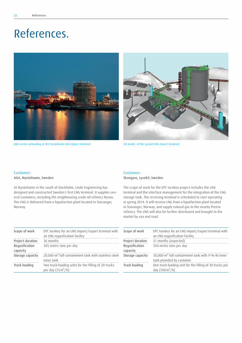
Customer:AGA, Nynäshamn, Sweden
At Nynäshamn in the south of Stockholm, Linde Engineering has designed and constructed Sweden’s first LNG terminal. It supplies sev-eral customers, including the neighbouring crude oil refinery Nynas. The LNG is delivered from a liquefaction plant located in Stavanger, Norway.
Customer:Skangass, Lysekil, Sweden
The scope of work for the EPC turnkey project includes the LNG terminal and the interface management for the integration of the LNG storage tank. The receiving terminal is scheduled to start operating in spring 2014. It will receive LNG from a liquefaction plant located in Stavanger, Norway, and supply natural gas to the nearby Preem refinery. The LNG will also be further distributed and brought to the market by sea and road.
LNG carrier unloading at the Nynäshamn LNG import terminal 3D model of the Lysekil LNG import terminal
Scope of work EPC turnkey for an LNG import/export terminal with an LNG regasification facility
Project duration 36 monthsRegasification capacity
305 metric tons per day
Storage capacity 20,000-m³ full-containment tank with stainless-steel inner tank
Truck loading Two truck-loading units for the filling of 20 trucks per day (75 m³/h)
Scope of work EPC turnkey for an LNG import/export terminal with an LNG regasification facility
Project duration 21 months (expected)Regasification capacity
504 metric tons per day
Storage capacity 30,000-m³ full-containment tank with 9-%-Ni inner tank provided by customer
Truck loading One truck-loading unit for the filling of 30 trucks per day (100 m³/h)
23References
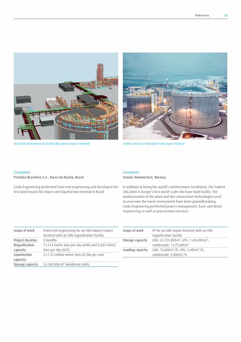
Customer:Petróleo Brasileiro S.A., Barra do Riacho, Brazil
Linde Engineering performed front-end engineering and developed the first land-based LNG import and liquefaction terminal in Brazil.
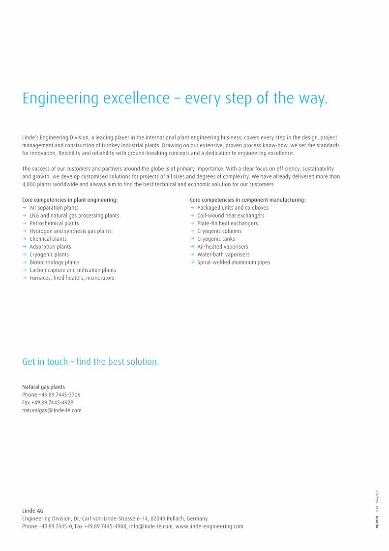
Customer:Statoil, Hammerfest, Norway
In addition to being the world’s northernmost installation, the Snøhvit LNG plant is Europe’s first world-scale LNG base-load facility. The modularisation of the plant and the construction technologies used to overcome the harsh environment have been groundbreaking. Linde Engineering performed project management, basic and detail engineering as well as procurement services.
3D model of the Barra do Riacho LNG import/export terminal Snøhvit LNG base-load plant with export terminal
Scope of work Front-end engineering for an LNG import/export terminal with an LNG regasification facility
Project duration 9 monthsRegasification capacity
11,214 metric tons per day (AAV) and 5,607 metric tons per day (SCV)
Liquefaction capacity
2 x 1.25 million metric tons of LNG per year
Storage capacity 2 x 160,000-m³ membrane tanks
Scope of work EP for an LNG export terminal with an LNG regasification facility
Storage capacity LNG: 2 x 125,000 m3; LPG: 1 x 45,000 m3; condensate: 1 x 75,000 m3
Loading capacity LNG: 12,600 m3/h; LPG: 3,400 m3/h; condensate: 4,800 m3/h
Natural gas plantsPhone +49.89.7445-3706Fax [email protected]
Get in touch – find the best solution.
Linde AGEngineering Division, Dr.-Carl-von-Linde-Strasse 6 –14, 82049 Pullach, GermanyPhone +49.89.7445-0, Fax +49.89.7445-4908, [email protected], www.linde-engineering.com
Engineering excellence – every step of the way.
Linde’s Engineering Division, a leading player in the international plant engineering business, covers every step in the design, projectmanagement and construction of turnkey industrial plants. Drawing on our extensive, proven process know-how, we set the standardsfor innovation, flexibility and reliability with ground-breaking concepts and a dedication to engineering excellence.
The success of our customers and partners around the globe is of primary importance. With a clear focus on efficiency, sustainabilityand growth, we develop customised solutions for projects of all sizes and degrees of complexity. We have already delivered more than4,000 plants worldwide and always aim to find the best technical and economic solution for our customers.
Core competencies in plant engineering: → Air separation plants → LNG and natural gas processing plants → Petrochemical plants → Hydrogen and synthesis gas plants → Chemical plants → Adsorption plants → Cryogenic plants → Biotechnology plants → Carbon capture and utilisation plants → Furnaces, fired heaters, incinerators
Core competencies in component manufacturing: → Packaged units and coldboxes → Coil-wound heat exchangers → Plate-fin heat exchangers → Cryogenic columns → Cryogenic tanks → Air-heated vaporisers → Water-bath vaporisers → Spiral-welded aluminium pipes
NG.B
1EN
111
4 – &
AA/L
&P