Embed Size (px)
Citation preview

Ultracapacitors ! Microelectronics ! High-Voltage Capacitors
Gateway to a New Thinking in Energy Management - Ultracapacitors
Ultracapacitors ! Microelectronics ! High-Voltage Capacitors
What is an Ultracapacitor?
Supercapacitor?
Electrochemical Double Layer Capacitor?
Energy Storage Capacitor?

Ultracapacitors ! Microelectronics ! High-Voltage Capacitors
Science of the Technology
C = εεεεr A/dMinimize (d)Maximize (A)
E = 1/2 CV2
Dielectric
Thin Film Electrode
Electrolyte
ECDL
Separator
" A 100-year-old technology, enhanced by modern materials
"Based on polarization of an electrolyte, high surface area electrodes and extremely small charge separation
Ultracapacitors ! Microelectronics ! High-Voltage Capacitors
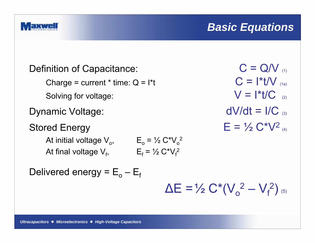
Basic Equations
Definition of Capacitance: C = Q/V (1)
Charge = current * time: Q = I*t C = I*t/V (1a)
Solving for voltage: V = I*t/C (2)
Dynamic Voltage: dV/dt = I/C (3)
Stored Energy E = ½ C*V2(4)
At initial voltage Vo, Eo = ½ C*Vo2
At final voltage Vf, Ef = ½ C*Vf2
Delivered energy = Eo � Ef
∆E =½ C*(Vo2 � Vf
2) (5)
Ultracapacitors ! Microelectronics ! High-Voltage Capacitors
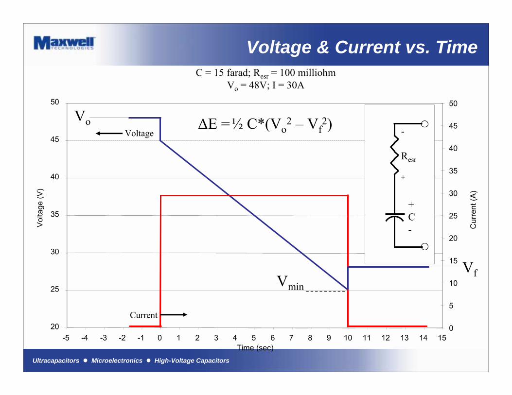
Voltage & Current vs. TimeC = 15 farad; Resr = 100 milliohm
Vo = 48V; I = 30A
-5 -4 -3 -2 -1 0 1 2 3 4 5 6 7 8 9 10 11 12 13 14 15Time (sec)
20
25
30
35
40
45
50
Vol
tage
(V)
0
5
10
15
20
25
30
35
40
45
50
Cur
rent
(A)
-
Resr
+
+C-
i
Voltage
Current
Vo
Vmin
Vf
V = Q/CdVesr = I*ResrdV/dt = I/C ; dV = I*dt/CdVtotal = I*dt/C + I*Resr∆E =½ C*(Vo2 � Vf
2)
Ultracapacitors ! Microelectronics ! High-Voltage Capacitors
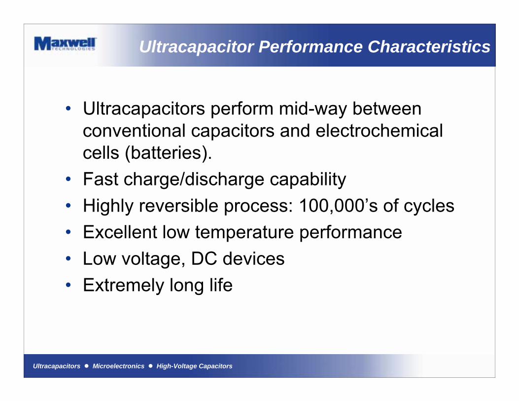
Ultracapacitor Performance Characteristics
� Ultracapacitors perform mid-way between conventional capacitors and electrochemical cells (batteries).
� Fast charge/discharge capability� Highly reversible process: 100,000�s of cycles� Excellent low temperature performance� Low voltage, DC devices� Extremely long life

Ultracapacitors ! Microelectronics ! High-Voltage Capacitors
Technology Comparison
AvailablePerformance
Lead AcidBattery
Ultracapacitor ElectrolyticCapacitor
Charge Time 1 to 5 hrs 0.3 to 30 s 10-3 to 10-6 sDischarge Time 0.3 to 3 hrs 0.3 to 30 s 10-3 to 10-6 sEnergy (Wh/kg) 10 to 100 1 to 10 < 0.1Cycle Life 1,000 >500,000 >500,000Specific Power (W/kg) <1000 <10,000 <100,000Charge/discharge efficiency
0.7 to 0.85 0.85 to 0.98 >0.95

Ultracapacitors ! Microelectronics ! High-Voltage Capacitors
Technology Comparison (page 2)
0,01
0,1
1
10
100
1000
10 100 1000 10000
Power Density/[W/kg]
Ener
gy D
ensi
ty/[W
h/kg
]
Double-Layer Capacitors
10h 1h0.1h
36sec
3.6sec
0.36sec
Lead AcidBattery
Ni/Cd
Li-Battery
Electrolytics
Boostcap
Fuel Cells
36msec
10h

Ultracapacitors ! Microelectronics ! High-Voltage Capacitors
0
1
2
3
4Efficiency
Self Discharge
Availability
Cycle Stability
Energy Density
Power Density
Energy Cost
Power Cost
System Cost
Safety
Recycling
Environment
Temperature Range
Charge AcceptanceUltracapsPb-AGMNiMHLi Ion
Ultracapacitors vs Batteries
Ultracapacitors ! Microelectronics ! High-Voltage Capacitors
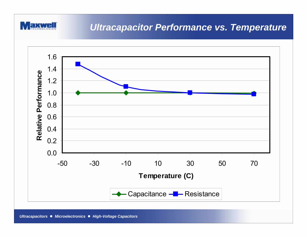
Ultracapacitor Performance vs. Temperature
0.0
0.2
0.4
0.6
0.8
1.0
1.2
1.4
1.6
-50 -30 -10 10 30 50 70
Temperature (C)
Rel
ativ
e Pe
rfor
man
ce
Capacitance Resistance
Ultracapacitors ! Microelectronics ! High-Voltage Capacitors
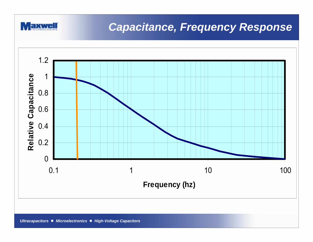
Capacitance, Frequency Response
0
0.2
0.4
0.6
0.8
1
1.2
0.1 1 10 100
Frequency (hz)
Rela
tive
Capa
cita
nce
Ultracapacitors ! Microelectronics ! High-Voltage Capacitors
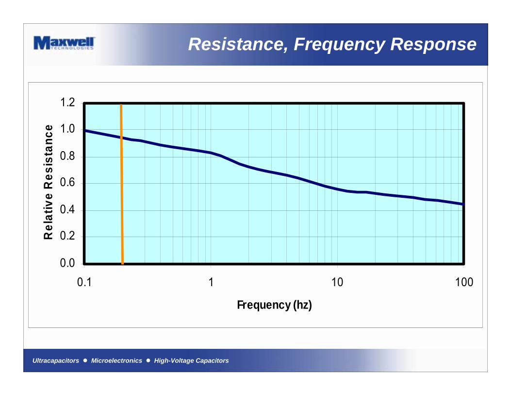
Resistance, Frequency Response
0.0
0.2
0.4
0.6
0.8
1.0
1.2
0.1 1 10 100
Frequency (hz)
Rel
ativ
e R
esis
tanc
e

Ultracapacitors ! Microelectronics ! High-Voltage Capacitors
Ultracapacitor Aging
� Unlike batteries, Ultracapacitors do not have a hard end of life criteria.
� Ultracapacitors degradation is apparent by a gradual loss of capacitance and a gradual increase in resistance.
� End of life is when the capacitance and resistance is out of the application range and will differ depending on the application.
� Therefore life prediction is easily done.

Ultracapacitors ! Microelectronics ! High-Voltage Capacitors
Product Portfolio Range
PowerCache Modules" 50 V, 1.6 and 2.3 kWm
PC Series" 4 and 10 F" Modules rated at 5 and 15 V
BC Series (Power & Energy)" 120, 140, 310, 350 F" Modules and packs rated at 15 V
MC Series (Power & Energy)" 650, 1200, 1500, 2000, 2600, 3000 F" Modules rated at 16 V and 48 V
Ultracapacitors ! Microelectronics ! High-Voltage Capacitors
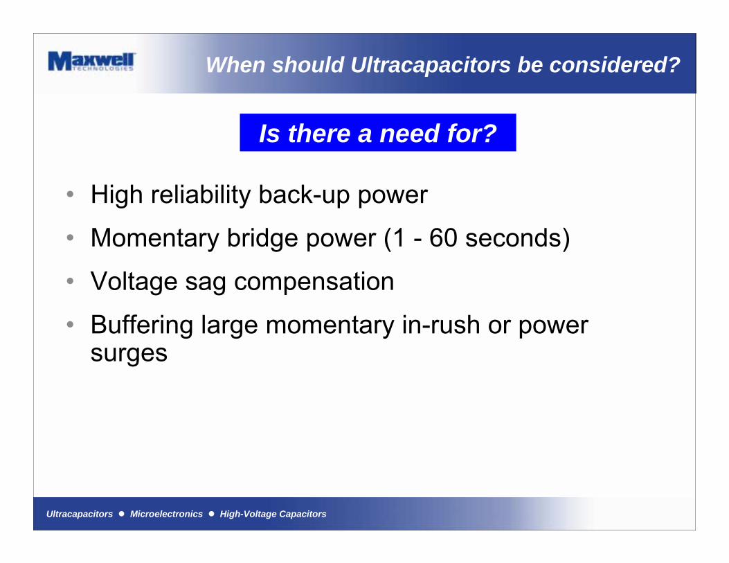
When should Ultracapacitors be considered?
� High reliability back-up power
� Momentary bridge power (1 - 60 seconds)
� Voltage sag compensation
� Buffering large momentary in-rush or power surges
Is there a need for?
Ultracapacitors ! Microelectronics ! High-Voltage Capacitors
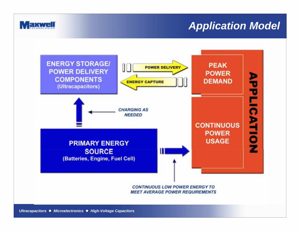
Application Model
Ultracapacitors ! Microelectronics ! High-Voltage Capacitors
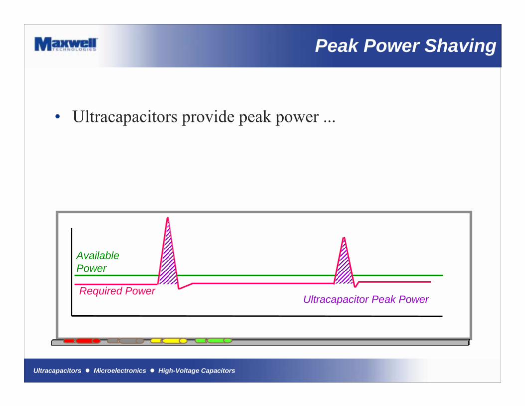
Peak Power Shaving� Ultracapacitors provide peak power ...
AvailablePower
Required PowerUltracapacitor Peak Power
Peak Power Shaving
Ultracapacitors ! Microelectronics ! High-Voltage Capacitors
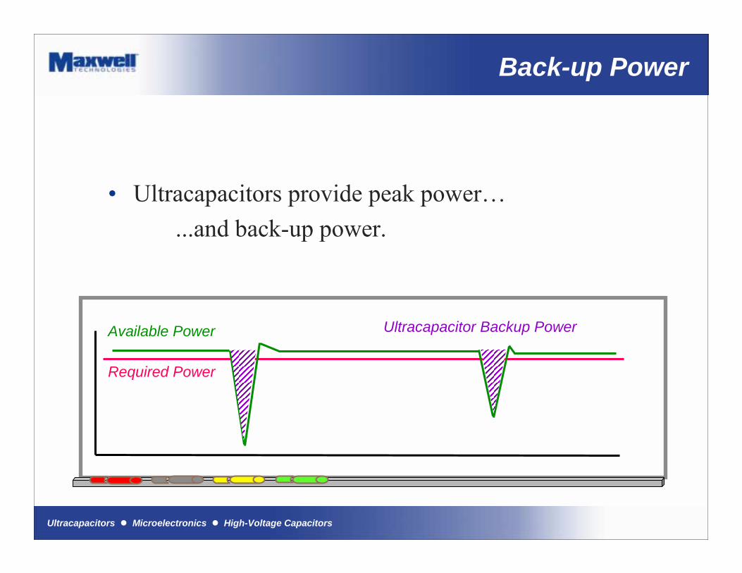
Back-Up Power Support
� Ultracapacitors provide peak power�...and back-up power.
Required Power
Available Power Ultracapacitor Backup Power
Back-up Power
Ultracapacitors ! Microelectronics ! High-Voltage Capacitors
Ultracapacitor Market
Ultracapacitors ! Microelectronics ! High-Voltage Capacitors
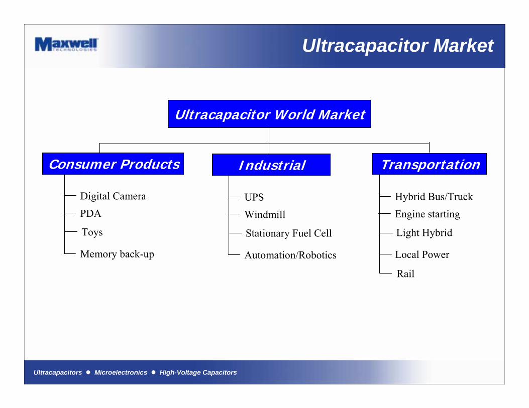
Ultracapacitor Market
Ultracapacitor World Market
Consumer Products
Digital CameraPDA
Toys
Memory back-up
UPSWindmill
Industrial
Stationary Fuel Cell
Automation/Robotics
Transportation
Hybrid Bus/TruckEngine starting
Light Hybrid
Local Power
Rail
Ultracapacitors ! Microelectronics ! High-Voltage Capacitors
Ultracapacitors ! Microelectronics ! High-Voltage Capacitors
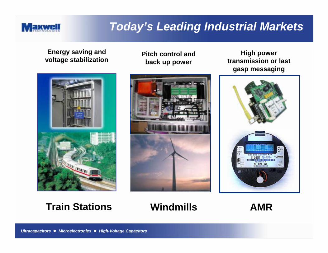
Energy saving and voltage stabilization
Today’s Leading Industrial Markets
Pitch control and back up power
High power transmission or last
gasp messaging
Train Stations Windmills AMR
Ultracapacitors ! Microelectronics ! High-Voltage Capacitors
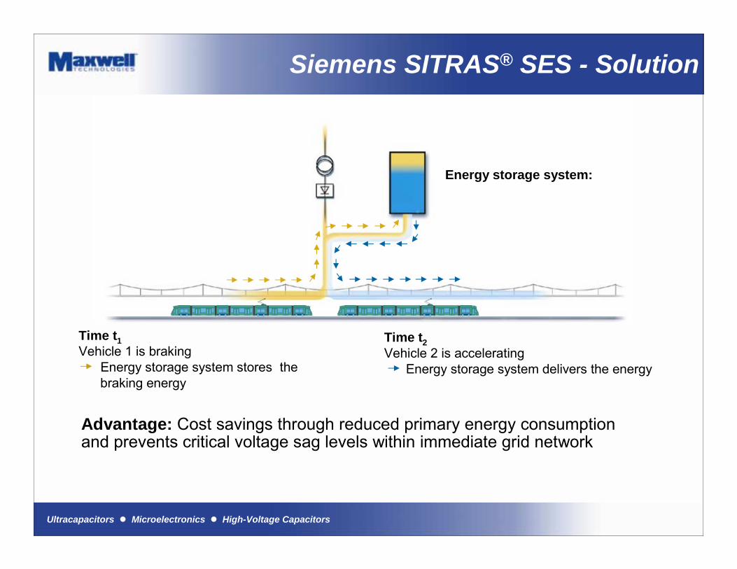
Energy storage system:
Time t1Vehicle 1 is braking
Energy storage system stores thebraking energy
Time t2Vehicle 2 is accelerating
Energy storage system delivers the energy
Siemens SITRAS® SES - Solution
Advantage: Cost savings through reduced primary energy consumption and prevents critical voltage sag levels within immediate grid network
Ultracapacitors ! Microelectronics ! High-Voltage Capacitors
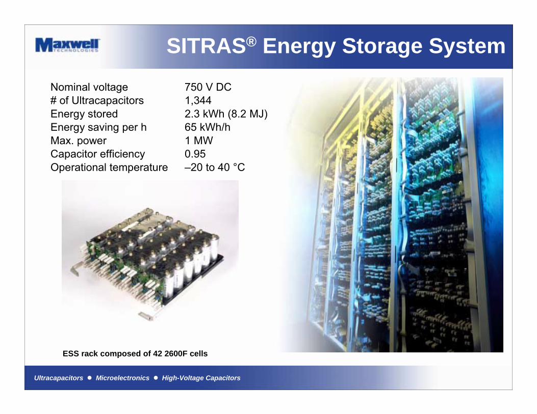
Nominal voltage 750 V DC# of Ultracapacitors 1,344Energy stored 2.3 kWh (8.2 MJ)Energy saving per h 65 kWh/hMax. power 1 MWCapacitor efficiency 0.95Operational temperature �20 to 40 °C
SITRAS® Energy Storage System
ESS rack composed of 42 2600F cells
Ultracapacitors ! Microelectronics ! High-Voltage Capacitors
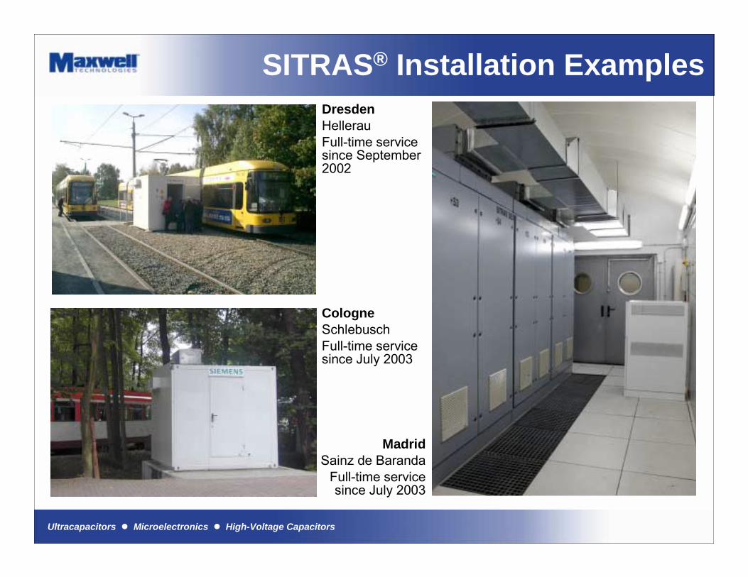
SITRAS® Installation Examples DresdenHellerauFull-time service since September 2002
CologneSchlebuschFull-time service since July 2003
MadridSainz de Baranda
Full-time service since July 2003

Ultracapacitors ! Microelectronics ! High-Voltage Capacitors
Wind Turbine Pitch Systems
" Modern wind turbinesconsist of three-bladed variable speed turbines
" Independent electro-mechanical propulsion units control and adjust the rotor-blades
" Latest technology uses the wind not only to produce wind energy but also for its own safety

Ultracapacitors ! Microelectronics ! High-Voltage Capacitors
Pitch System Storage Systems
" Each pitch systems is equipped with an ultracapacitor emergency power supply
" Ultracapacitors represent an optimum emergency power supply system due to their� Enhanced level of
safety� High reliability� Efficiency� Scalability
75 V, 81 F ultracapacitor module
4 modules are put in series to power 300 V
pitch systems of 3-5 MW wind power plants
Switch box including 2600F ultracapacitors
Ultracapacitors ! Microelectronics ! High-Voltage Capacitors
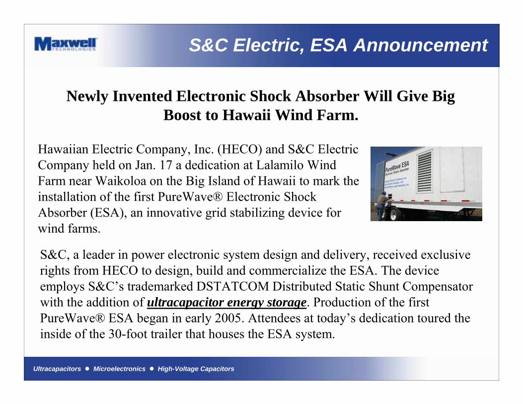
S&C Electric, ESA Announcement
Newly Invented Electronic Shock Absorber Will Give Big Boost to Hawaii Wind Farm.
Hawaiian Electric Company, Inc. (HECO) and S&C Electric Company held on Jan. 17 a dedication at Lalamilo Wind Farm near Waikoloa on the Big Island of Hawaii to mark the installation of the first PureWave® Electronic Shock Absorber (ESA), an innovative grid stabilizing device for wind farms.
S&C, a leader in power electronic system design and delivery, received exclusive rights from HECO to design, build and commercialize the ESA. The device employs S&C�s trademarked DSTATCOM Distributed Static Shunt Compensator with the addition of ultracapacitor energy storage. Production of the first PureWave® ESA began in early 2005. Attendees at today�s dedication toured the inside of the 30-foot trailer that houses the ESA system.

Ultracapacitors ! Microelectronics ! High-Voltage Capacitors
S&C Electric, ESA
Ultracapacitors ! Microelectronics ! High-Voltage Capacitors
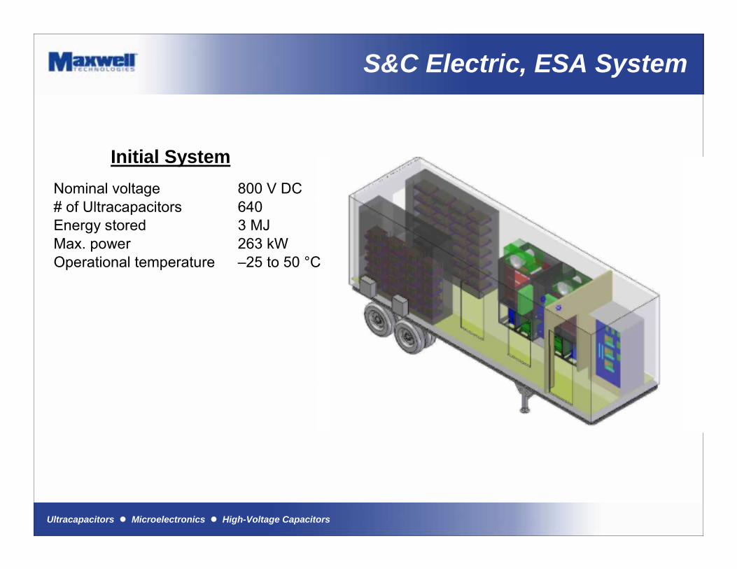
S&C Electric, ESA System
Nominal voltage 800 V DC# of Ultracapacitors 640Energy stored 3 MJMax. power 263 kWOperational temperature �25 to 50 °C
Initial System
Ultracapacitors ! Microelectronics ! High-Voltage Capacitors
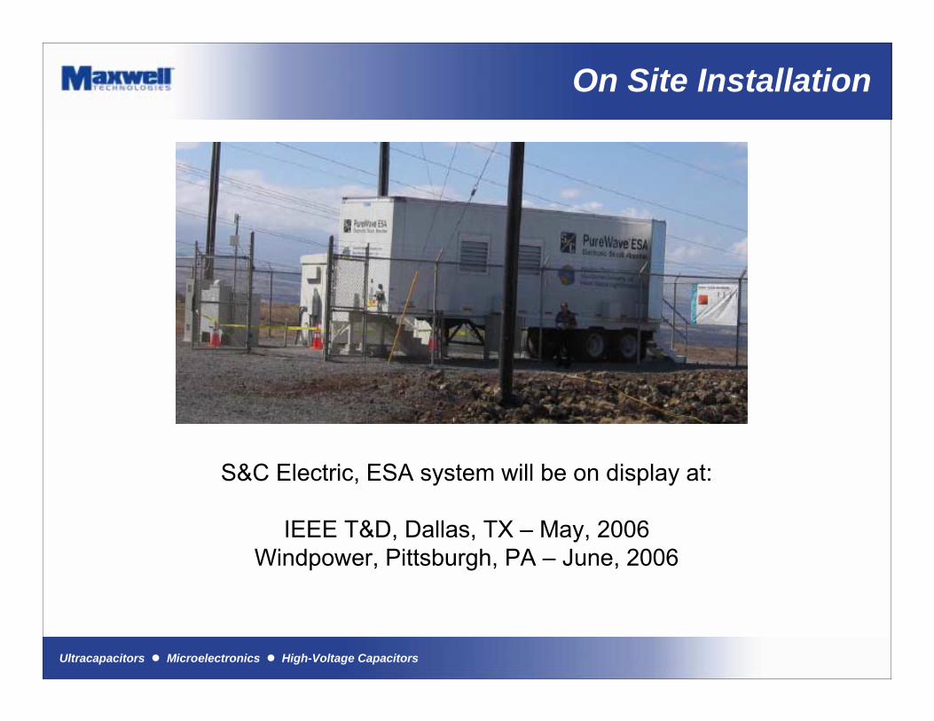
On Site Installation
S&C Electric, ESA system will be on display at:
IEEE T&D, Dallas, TX � May, 2006Windpower, Pittsburgh, PA � June, 2006
Ultracapacitors ! Microelectronics ! High-Voltage Capacitors
Northern Power, Energy Bridge
CEC Awards Grant to Northern Power to Integrate Advanced Power Electronics TechnologyWAITSFIELD, Vt. -- Northern Power Systems, a subsidiary of Distributed Energy Systems Corp. (NASDAQ: DESC), has been contracted to design, engineer and install an advanced energy storage system for the Palmdale Water District's Southern California water treatment plant and adjacent pumping facility.
Northern's Power Technology Group (PTG) will integrate its advanced power conversion, switching and controls solutions with Maxwell Technologies ultracapacitor modules to create a system that will provide critical load support for the protected loads. In the event of a grid outage, the high- reliability system will be capable of creating short-term power as the transition is made to on-site or backup generation power. The system will be able to support 450 kW for 20 - 60 seconds depending on the loads, enough time to bring a generator on line and avoid any interruption in power at the Palmdale facility.
Ultracapacitors ! Microelectronics ! High-Voltage Capacitors
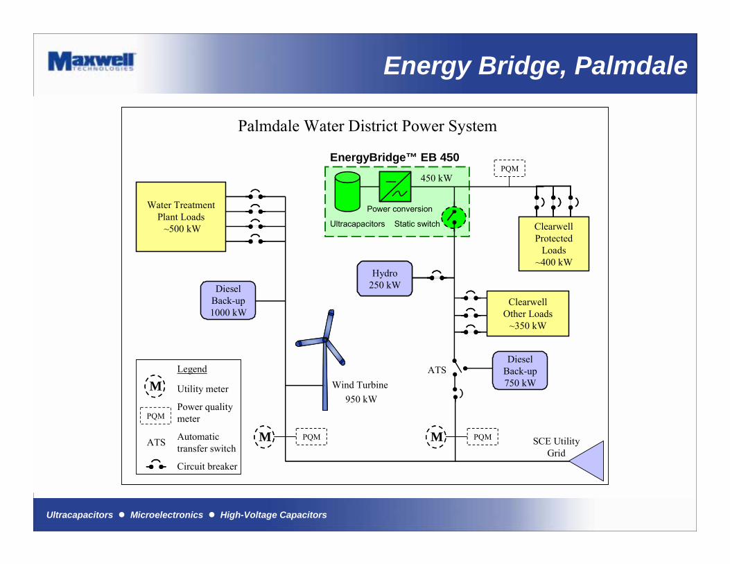
ClearwellProtected
Loads~400 kW
Diesel Back-up1000 kW
Diesel Back-up750 kW
Palmdale Water District Power System
SCE UtilityGrid
Wind Turbine950 kW
Static switch
Water TreatmentPlant Loads
~500 kW
PQM
PQM
ClearwellOther Loads
~350 kW
Hydro250 kWHydro
250 kW
MM
ATS
PQMMM
EnergyBridge™ EB 450
MM
PQM
ATS
Utility meter
Power quality meter
Automatic transfer switch
Circuit breaker
Legend
Ultracapacitors
Power conversion
450 kW
Energy Bridge, Palmdale
Ultracapacitors ! Microelectronics ! High-Voltage Capacitors
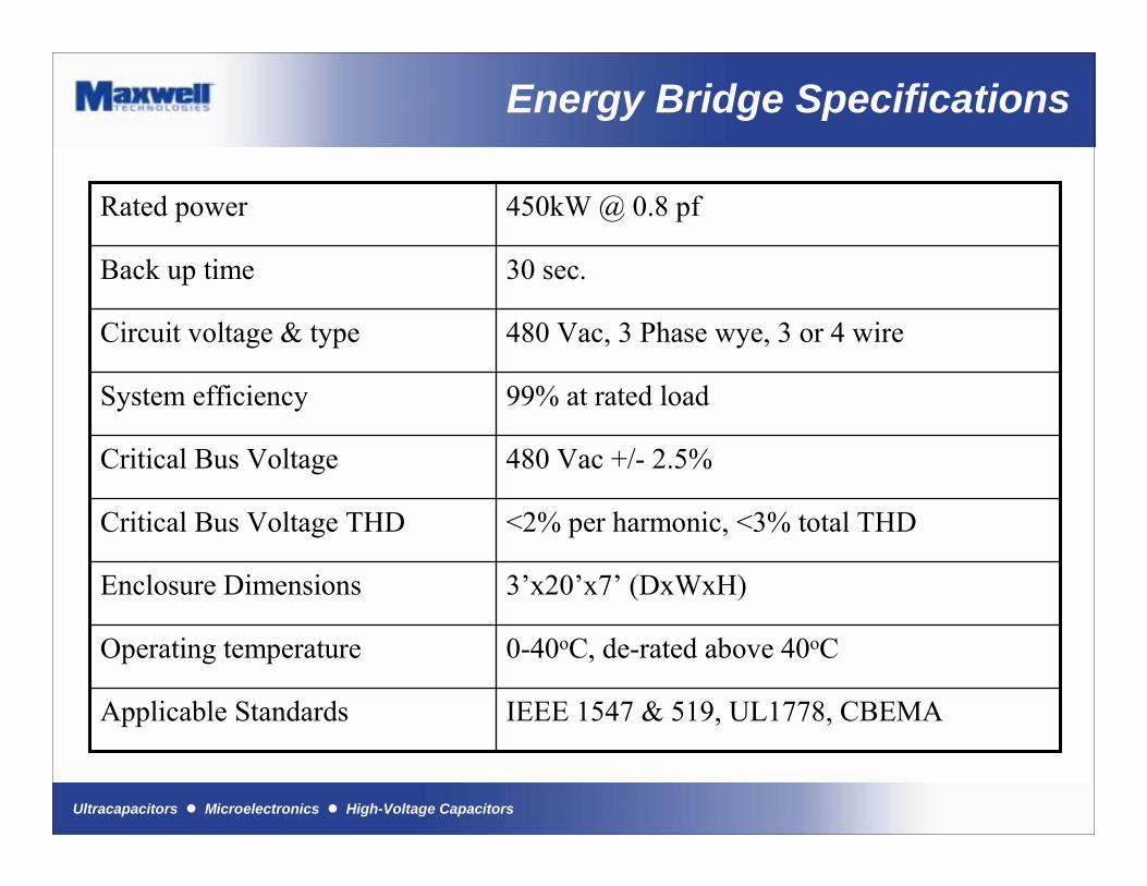
Energy Bridge Specifications
480 Vac, 3 Phase wye, 3 or 4 wireCircuit voltage & type
<2% per harmonic, <3% total THDCritical Bus Voltage THD
480 Vac +/- 2.5%Critical Bus Voltage
99% at rated loadSystem efficiency
30 sec.Back up time
450kW @ 0.8 pfRated power
IEEE 1547 & 519, UL1778, CBEMAApplicable Standards
0-40oC, de-rated above 40oCOperating temperature
3�x20�x7� (DxWxH)Enclosure Dimensions
Ultracapacitors ! Microelectronics ! High-Voltage Capacitors
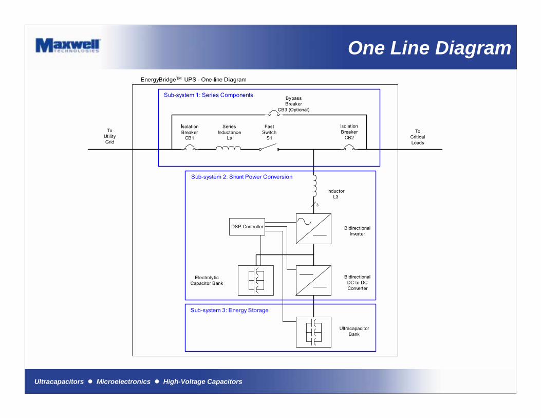
One Line Diagram
SeriesInductance
Ls
FastSwitch
S1
BypassBreaker
CB3 (Optional)
IsolationBreaker
CB2
IsolationBreaker
CB1
BidirectionalInverter
BidirectionalDC to DCConverter
UltracapacitorBank
3
ToUtilityGrid
ToCriticalLoads
InductorL3
ElectrolyticCapacitor Bank
Sub-system 2: Shunt Power Conversion
Sub-system 1: Series Components
DSP Controller
EnergyBridgeTM UPS - One-line Diagram
Sub-system 3: Energy Storage
Ultracapacitors ! Microelectronics ! High-Voltage Capacitors
Sizing Your System
Ultracapacitors ! Microelectronics ! High-Voltage Capacitors
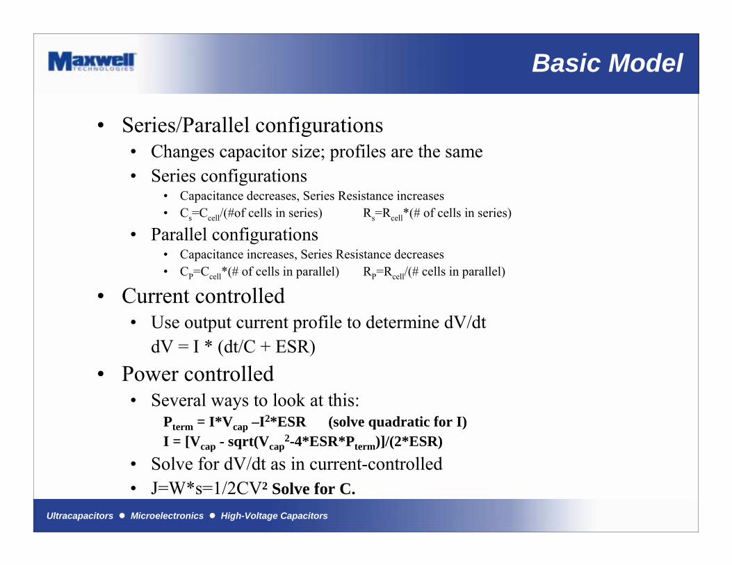
Basic Model
� Series/Parallel configurations� Changes capacitor size; profiles are the same� Series configurations
� Capacitance decreases, Series Resistance increases� Cs=Ccell/(#of cells in series) Rs=Rcell*(# of cells in series)
� Parallel configurations� Capacitance increases, Series Resistance decreases� CP=Ccell*(# of cells in parallel) RP=Rcell/(# cells in parallel)
� Current controlled� Use output current profile to determine dV/dt
dV = I * (dt/C + ESR)� Power controlled
� Several ways to look at this:Pterm = I*Vcap –I2*ESR (solve quadratic for I)I = [Vcap - sqrt(Vcap
2-4*ESR*Pterm)]/(2*ESR)� Solve for dV/dt as in current-controlled� J=W*s=1/2CV2 Solve for C.
Ultracapacitors ! Microelectronics ! High-Voltage Capacitors
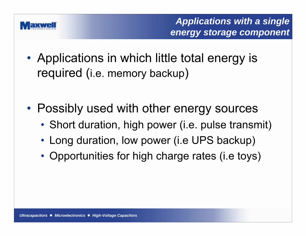
Applications with a singleenergy storage component
� Applications in which little total energy is required (i.e. memory backup)
� Possibly used with other energy sources� Short duration, high power (i.e. pulse transmit)� Long duration, low power (i.e UPS backup)� Opportunities for high charge rates (i.e toys)
Ultracapacitors ! Microelectronics ! High-Voltage Capacitors
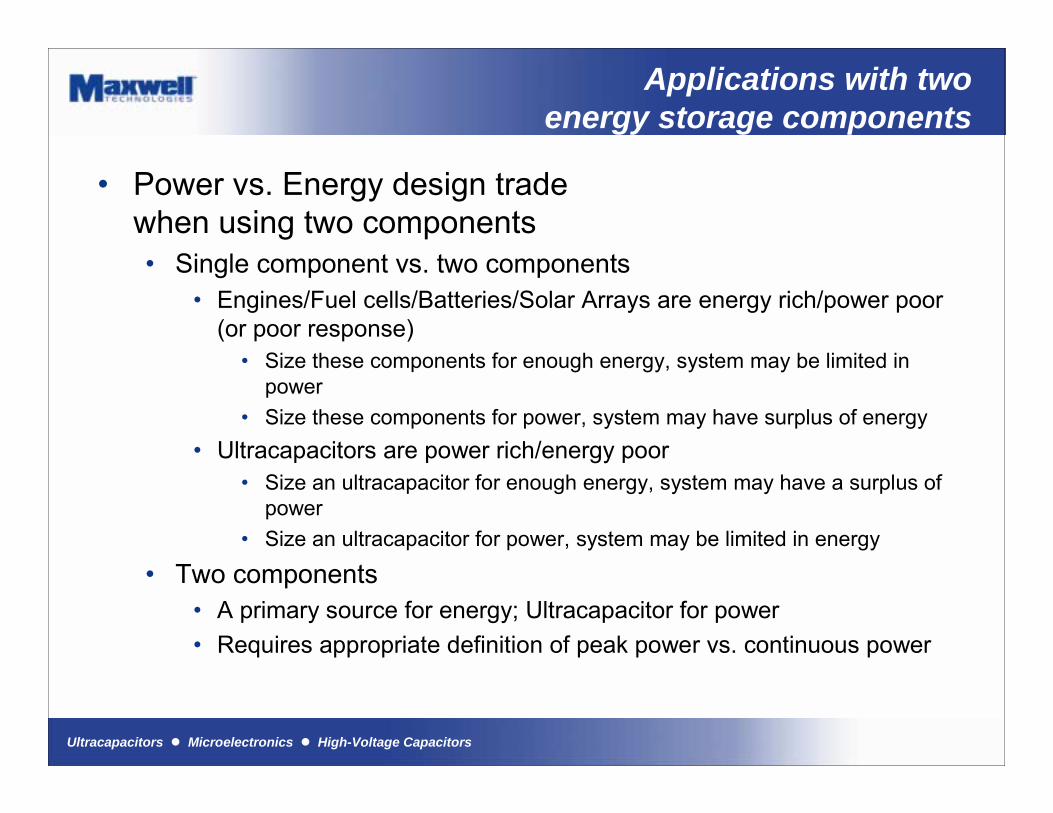
Applications with twoenergy storage components
� Power vs. Energy design tradewhen using two components� Single component vs. two components
� Engines/Fuel cells/Batteries/Solar Arrays are energy rich/power poor (or poor response)
� Size these components for enough energy, system may be limited in power
� Size these components for power, system may have surplus of energy� Ultracapacitors are power rich/energy poor
� Size an ultracapacitor for enough energy, system may have a surplus of power
� Size an ultracapacitor for power, system may be limited in energy
� Two components� A primary source for energy; Ultracapacitor for power� Requires appropriate definition of peak power vs. continuous power
Ultracapacitors ! Microelectronics ! High-Voltage Capacitors
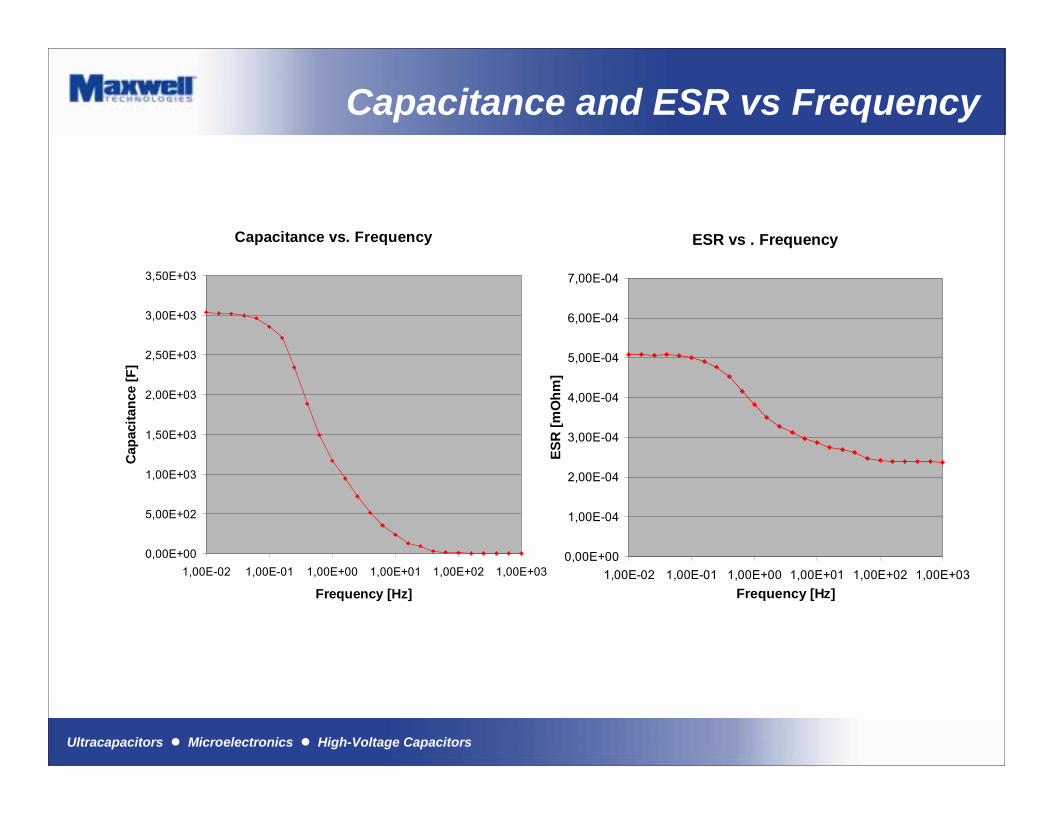
Capacitance and ESR vs Frequency
ESR vs . Frequency
0,00E+00
1,00E-04
2,00E-04
3,00E-04
4,00E-04
5,00E-04
6,00E-04
7,00E-04
1,00E-02 1,00E-01 1,00E+00 1,00E+01 1,00E+02 1,00E+03Frequency [Hz]
ESR
[mO
hm]
Capacitance vs. Frequency
0,00E+00
5,00E+02
1,00E+03
1,50E+03
2,00E+03
2,50E+03
3,00E+03
3,50E+03
1,00E-02 1,00E-01 1,00E+00 1,00E+01 1,00E+02 1,00E+03
Frequency [Hz]
Cap
acita
nce
[F]
Ultracapacitors ! Microelectronics ! High-Voltage Capacitors
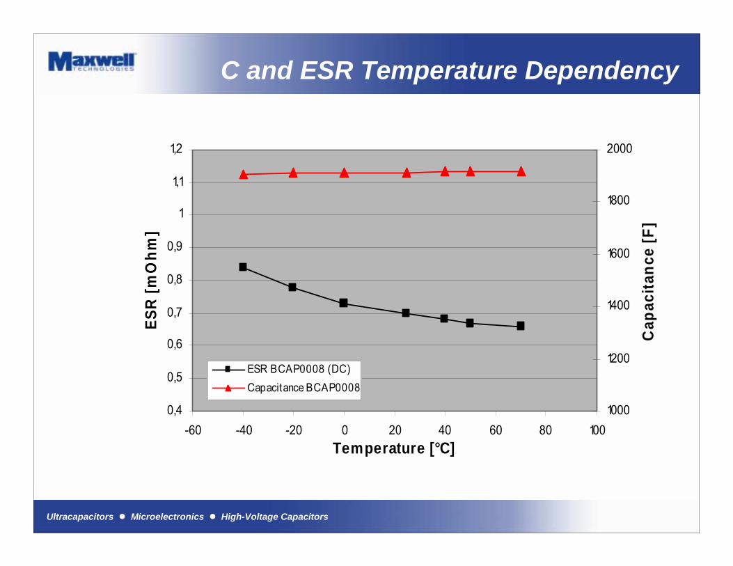
C and ESR Temperature Dependency
0,4
0,5
0,6
0,7
0,8
0,9
1
1,1
1,2
-60 -40 -20 0 20 40 60 80 100Temperature [°C]
ESR
[mO
hm]
1000
1200
1400
1600
1800
2000
Cap
acita
nce
[F]
ESR BCAP0008 (DC)Capacitance BCAP0008

Ultracapacitors ! Microelectronics ! High-Voltage Capacitors
BCAP Self Discharge
Self Discharge vs Temperature
30,0
40,0
50,0
60,0
70,0
80,0
90,0
100,0
0 2 4 6 8 10 12 14 16 18 20 22 24 26 28 30
Time [days]
% U
(t =
0)
- 35 °C
+ 5 °C
+ 25 °C
+ 65 °C

Ultracapacitors ! Microelectronics ! High-Voltage Capacitors
BCAP Cycling Capacity
90 A CC, 1.15-2.3 V, 25 s, RT
50.0
60.0
70.0
80.0
90.0
100.0
110.0
0 20000 40000 60000 80000 100000
Cycle Number
Cha
nge
in C
apac
itanc
e [%
]
0.0E+002.0E-044.0E-046.0E-048.0E-041.0E-031.2E-031.4E-031.6E-031.8E-032.0E-03
ESR
[Ohm
]
ESR
Capacitance
Ultracapacitors ! Microelectronics ! High-Voltage Capacitors
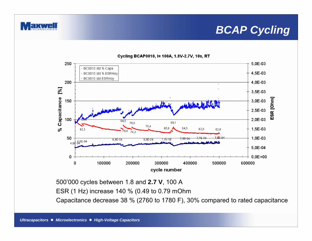
BCAP Cycling
500�000 cycles between 1.8 and 2.7 V, 100 AESR (1 Hz) increase 140 % (0.49 to 0.79 mOhmCapacitance decrease 38 % (2760 to 1780 F), 30% compared to rated capacitance
Ultracapacitors ! Microelectronics ! High-Voltage Capacitors
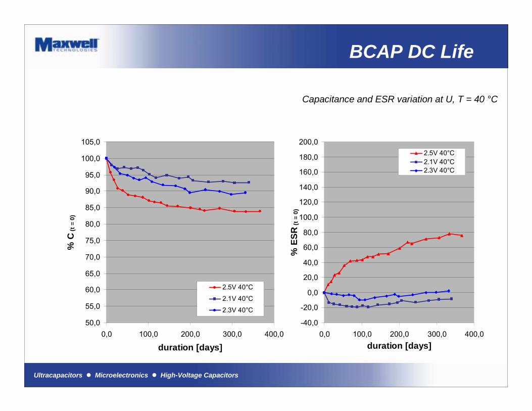
BCAP DC Life
Capacitance and ESR variation at U, T = 40 °C
50,0
55,0
60,0
65,0
70,0
75,0
80,0
85,0
90,0
95,0
100,0
105,0
0,0 100,0 200,0 300,0 400,0
duration [days]
% C
(t =
0)
2.5V 40°C
2.1V 40°C
2.3V 40°C
-40,0
-20,0
0,0
20,0
40,0
60,0
80,0
100,0
120,0
140,0
160,0
180,0
200,0
0,0 100,0 200,0 300,0 400,0duration [days]
% E
SR (t
= 0)
2.5V 40°C2.1V 40°C2.3V 40°C
Ultracapacitors ! Microelectronics ! High-Voltage Capacitors
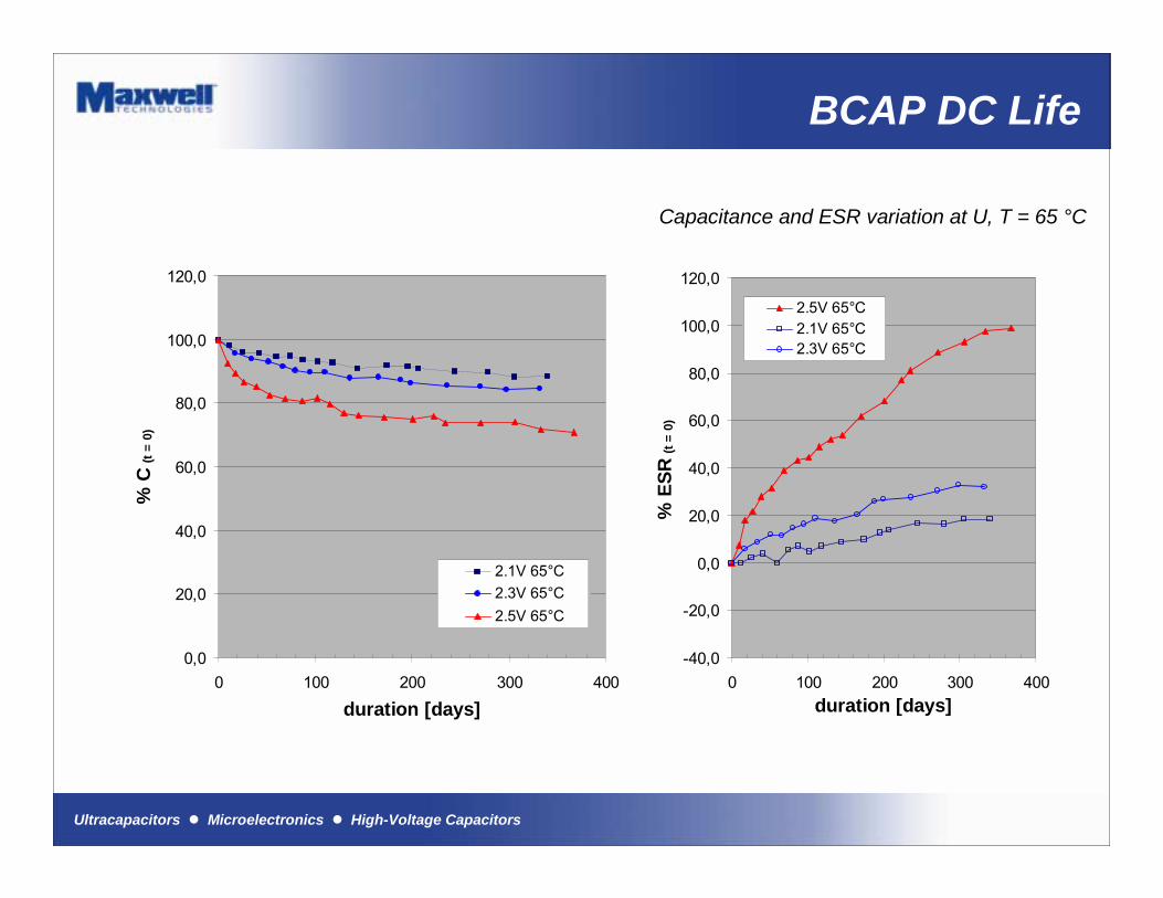
BCAP DC Life
0,0
20,0
40,0
60,0
80,0
100,0
120,0
0 100 200 300 400
duration [days]
% C
(t =
0)
2.1V 65°C2.3V 65°C2.5V 65°C
-40,0
-20,0
0,0
20,0
40,0
60,0
80,0
100,0
120,0
0 100 200 300 400duration [days]
% E
SR (t
= 0)
2.5V 65°C2.1V 65°C2.3V 65°C
Capacitance and ESR variation at U, T = 65 °C
Ultracapacitors ! Microelectronics ! High-Voltage Capacitors
Sizing Examples
Ultracapacitors ! Microelectronics ! High-Voltage Capacitors
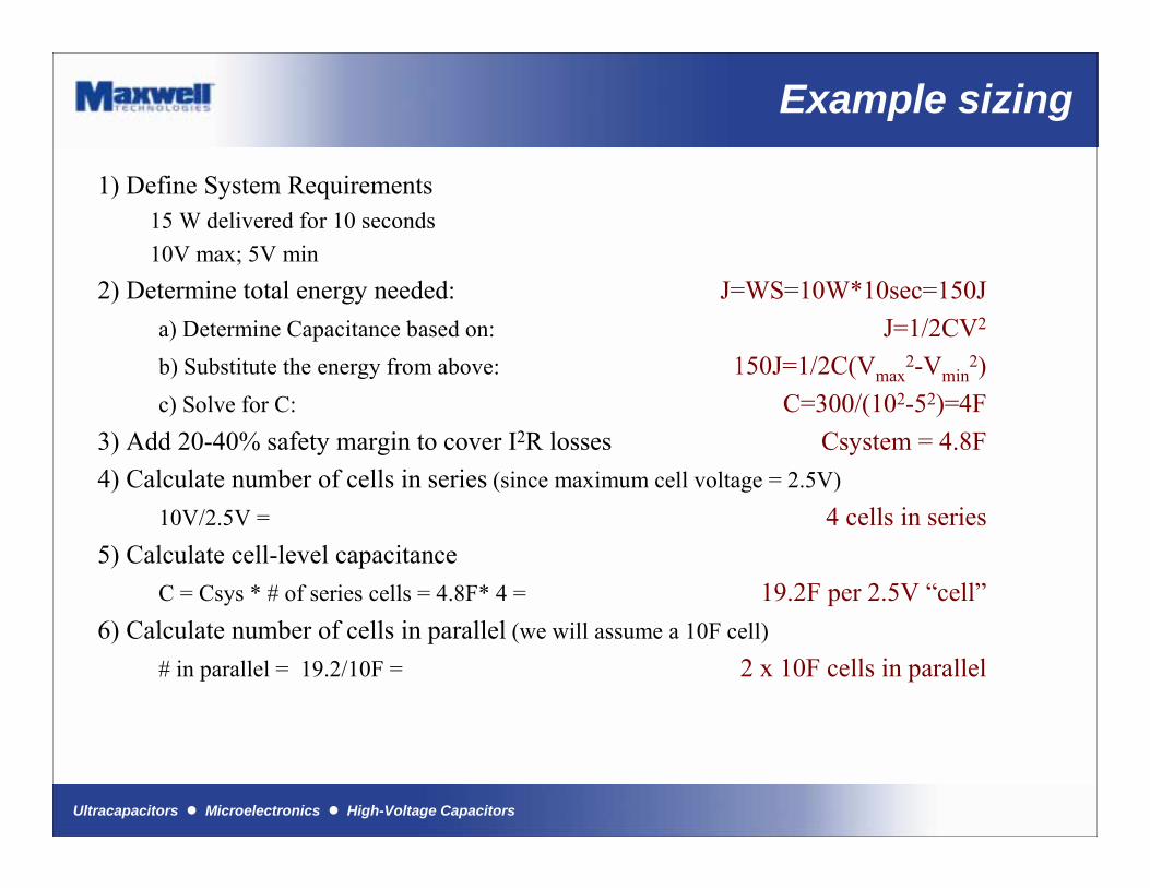
Example sizing
1) Define System Requirements15 W delivered for 10 seconds10V max; 5V min
2) Determine total energy needed: J=WS=10W*10sec=150Ja) Determine Capacitance based on: J=1/2CV2
b) Substitute the energy from above: 150J=1/2C(Vmax2-Vmin
2)c) Solve for C: C=300/(102-52)=4F
3) Add 20-40% safety margin to cover I2R losses Csystem = 4.8F4) Calculate number of cells in series (since maximum cell voltage = 2.5V)
10V/2.5V = 4 cells in series5) Calculate cell-level capacitance
C = Csys * # of series cells = 4.8F* 4 = 19.2F per 2.5V �cell�6) Calculate number of cells in parallel (we will assume a 10F cell)
# in parallel = 19.2/10F = 2 x 10F cells in parallel
Ultracapacitors ! Microelectronics ! High-Voltage Capacitors
Guidelines to Designing an Ultracapacitor System
Ultracapacitors ! Microelectronics ! High-Voltage Capacitors
Ultracapacitor Cell Balancing
Why Cell Balancing?
� Achieve cell to cell voltage balance
� Accounts for variations in capacitance and leakage current, initial charge and voltage dependent on capacitance, sustained voltage dependent on leakage current
� Reduces voltage stress on an individual cell
� Increase overall reliability of the individual cells
Ultracapacitors ! Microelectronics ! High-Voltage Capacitors
Ultracapacitor Cell Balancing
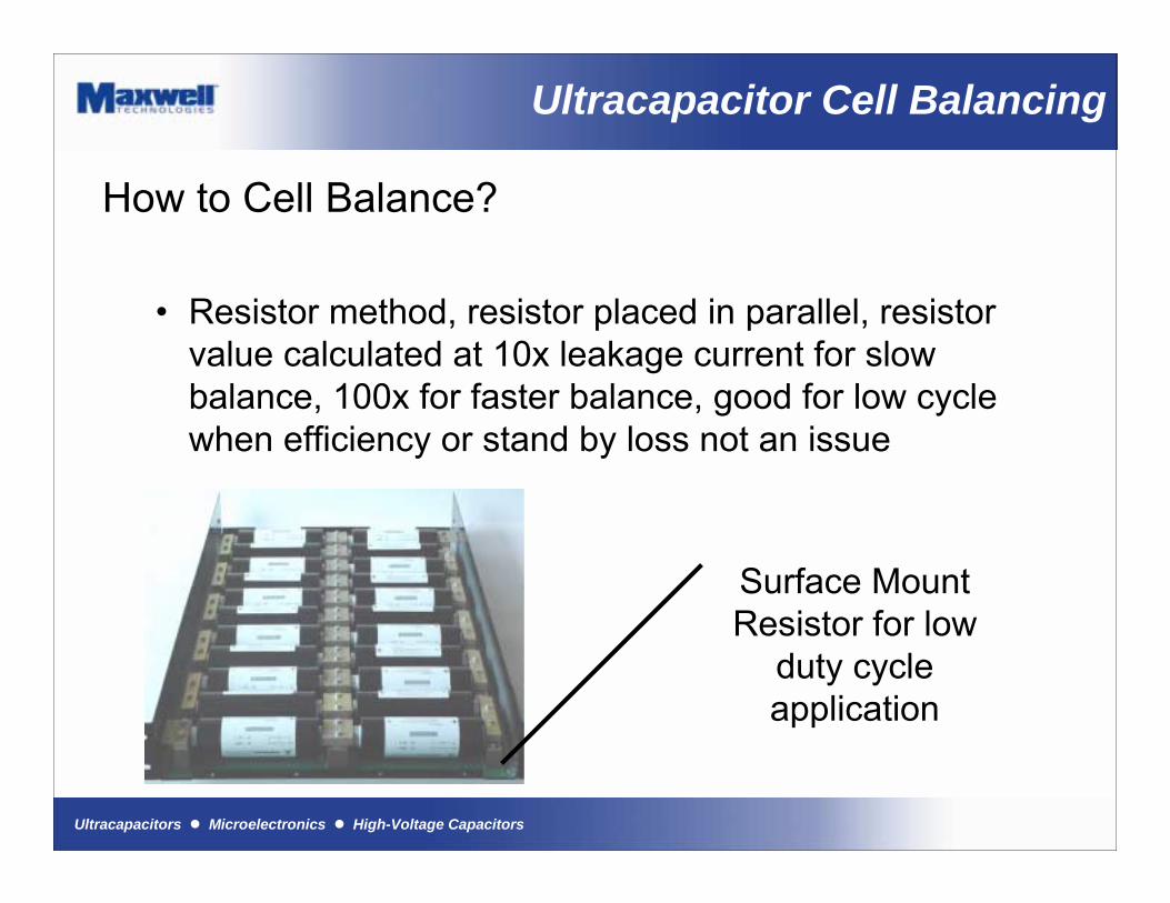
How to Cell Balance?
� Resistor method, resistor placed in parallel, resistor value calculated at 10x leakage current for slow balance, 100x for faster balance, good for low cycle when efficiency or stand by loss not an issue
Surface Mount Resistor for low
duty cycle application
Ultracapacitors ! Microelectronics ! High-Voltage Capacitors
Ultracapacitor Cell Balancing
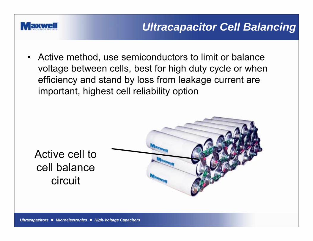
� Active method, use semiconductors to limit or balance voltage between cells, best for high duty cycle or when efficiency and stand by loss from leakage current are important, highest cell reliability option
Active cell to cell balance
circuit
Ultracapacitors ! Microelectronics ! High-Voltage Capacitors
Cell Balancing
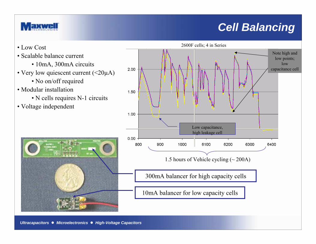
Low capacitance,high leakage cell
Note high and low points;
low capacitance cell
1.5 hours of Vehicle cycling (~ 200A)
� Low Cost� Scalable balance current
� 10mA, 300mA circuits� Very low quiescent current (<20µA)
� No on/off required� Modular installation
� N cells requires N-1 circuits� Voltage independent
2600F cells; 4 in Series
300mA balancer for high capacity cells
10mA balancer for low capacity cells
Ultracapacitors ! Microelectronics ! High-Voltage Capacitors
Cell Balancing
+
-
R3
R4
C2
C11M 1%
1M 1%
R1
R2
VPP
VNN
U1
499k 1%
475 1%Ultracapacitors
C1 Positiv e
C1-C2 Midpoint
C2 Negativ e
POS
NEG
+
-U1
VNN
VPP
R1100K 1%
R2100K 1%
R6
5.6 1% 1.5W
R549.9k 1%
C2
C1
Ultracapacitors
C1 Positive
C1-C2 Midpoint
C2 Negative
POS
NEG
Q1
Q2
TLV2211CDBV
R3
100
R4
100
MMBT2222AWT1
MMBT2907AWT1
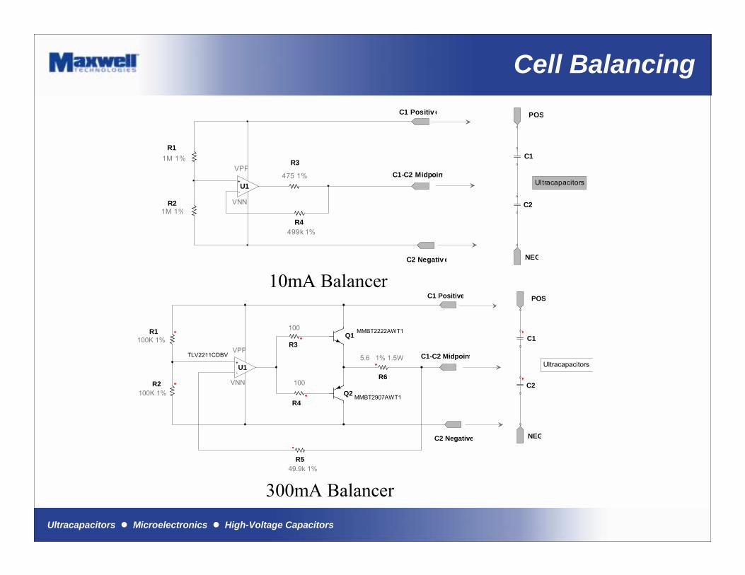
10mA Balancer
300mA Balancer
Ultracapacitors ! Microelectronics ! High-Voltage Capacitors
Cell Balancing
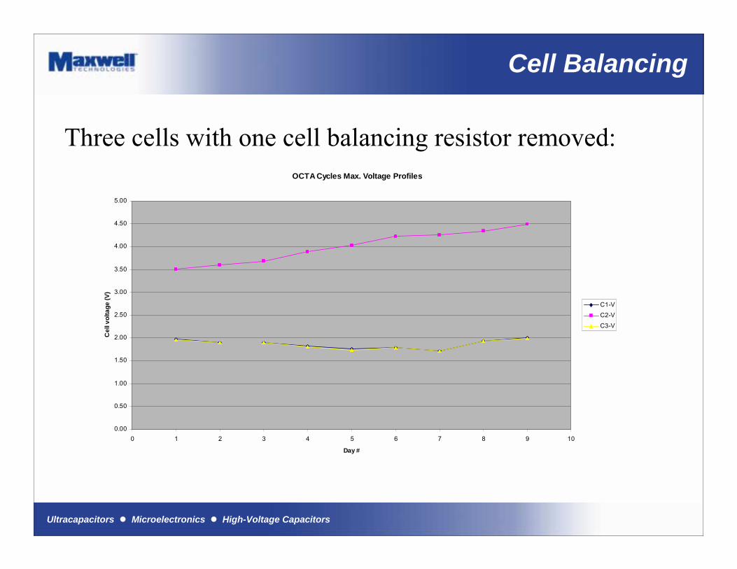
Three cells with one cell balancing resistor removed:OCTA Cycles Max. Voltage Profiles
0.00
0.50
1.00
1.50
2.00
2.50
3.00
3.50
4.00
4.50
5.00
0 1 2 3 4 5 6 7 8 9 10
Day #
Cel
l vol
tage
(V)
C1-VC2-V
C3-V

Ultracapacitors ! Microelectronics ! High-Voltage Capacitors
Ultracapacitor Packaging
Why Packaging?
� Ensure proper mechanical stress� Ensure robust low resistance interconnect� Ensure proper electrical isolation� Ensure proper thermal considerations� Ensure agency compliance� Increase overall cell reliability� Reduce or eliminate maintenance requirements
Ultracapacitors ! Microelectronics ! High-Voltage Capacitors
Ultracapacitor Packaging
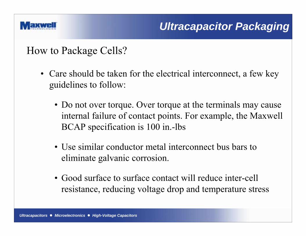
How to Package Cells?
� Care should be taken for the electrical interconnect, a few key guidelines to follow:
� Do not over torque. Over torque at the terminals may cause internal failure of contact points. For example, the Maxwell BCAP specification is 100 in.-lbs
� Use similar conductor metal interconnect bus bars to eliminate galvanic corrosion.
� Good surface to surface contact will reduce inter-cell resistance, reducing voltage drop and temperature stress
Ultracapacitors ! Microelectronics ! High-Voltage Capacitors
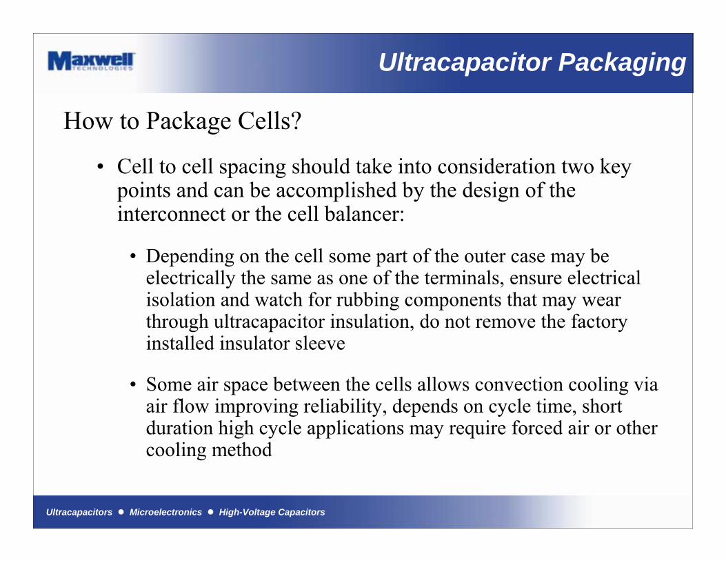
How to Package Cells?
� Cell to cell spacing should take into consideration two key points and can be accomplished by the design of the interconnect or the cell balancer:
� Depending on the cell some part of the outer case may be electrically the same as one of the terminals, ensure electricalisolation and watch for rubbing components that may wear through ultracapacitor insulation, do not remove the factory installed insulator sleeve
� Some air space between the cells allows convection cooling via air flow improving reliability, depends on cycle time, short duration high cycle applications may require forced air or othercooling method
Ultracapacitor Packaging
Ultracapacitors ! Microelectronics ! High-Voltage Capacitors
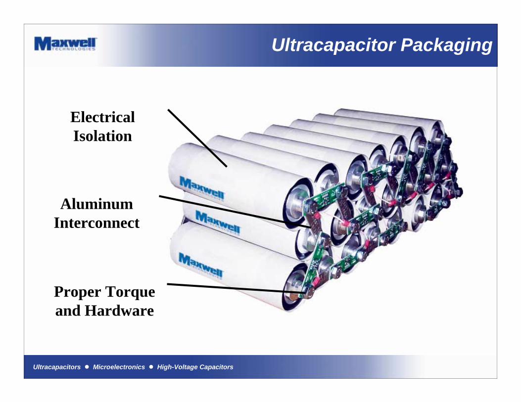
Ultracapacitor Packaging
ElectricalIsolation
Aluminum Interconnect
Proper Torqueand Hardware

Ultracapacitors ! Microelectronics ! High-Voltage Capacitors
Summary
Ultracapacitors ! Microelectronics ! High-Voltage Capacitors
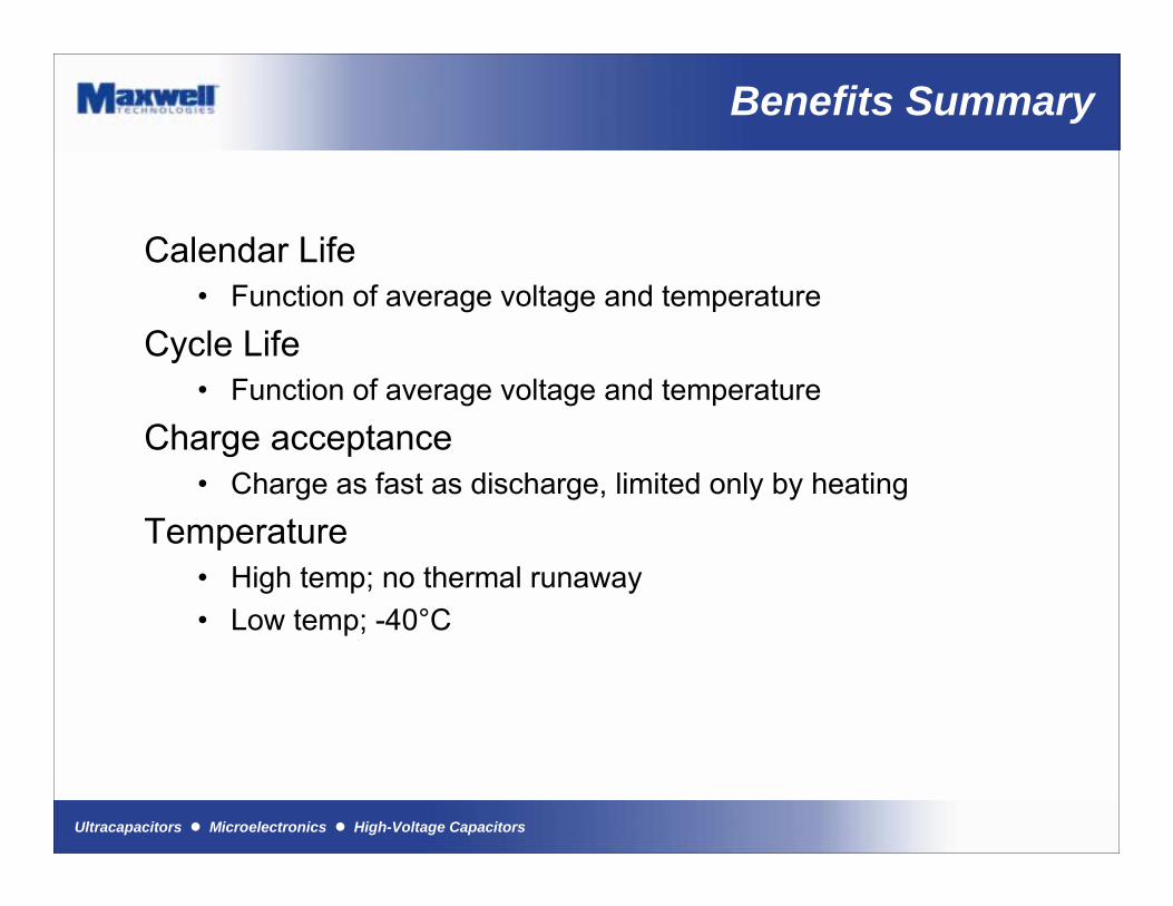
Benefits Summary
Calendar Life� Function of average voltage and temperature
Cycle Life� Function of average voltage and temperature
Charge acceptance� Charge as fast as discharge, limited only by heating
Temperature� High temp; no thermal runaway� Low temp; -40°C
Ultracapacitors ! Microelectronics ! High-Voltage Capacitors
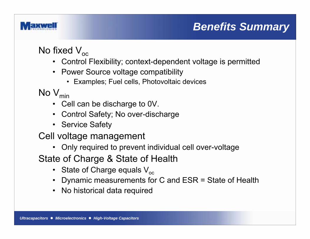
Benefits Summary
No fixed Voc� Control Flexibility; context-dependent voltage is permitted� Power Source voltage compatibility
� Examples; Fuel cells, Photovoltaic devices
No Vmin� Cell can be discharge to 0V.� Control Safety; No over-discharge� Service Safety
Cell voltage management� Only required to prevent individual cell over-voltage
State of Charge & State of Health� State of Charge equals Voc� Dynamic measurements for C and ESR = State of Health� No historical data required
Ultracapacitors ! Microelectronics ! High-Voltage Capacitors
About Maxwell
Capacitor Manufacturer since 1965
www.maxwell.com
Manufacturing facilities:US, Europe, Asia
Maxwell is a leading developer and manufacturer of innovative,cost-effective energy storageand power delivery solutions.
Certifications:ISO 9001:2000ISO/TS 16949
ISO 9002
Ultracapacitors ! Microelectronics ! High-Voltage Capacitors
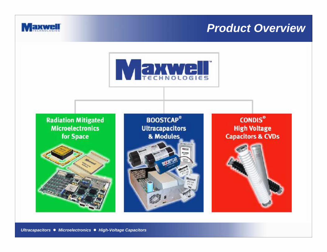
Product Overview
Ultracapacitors ! Microelectronics ! High-Voltage Capacitors
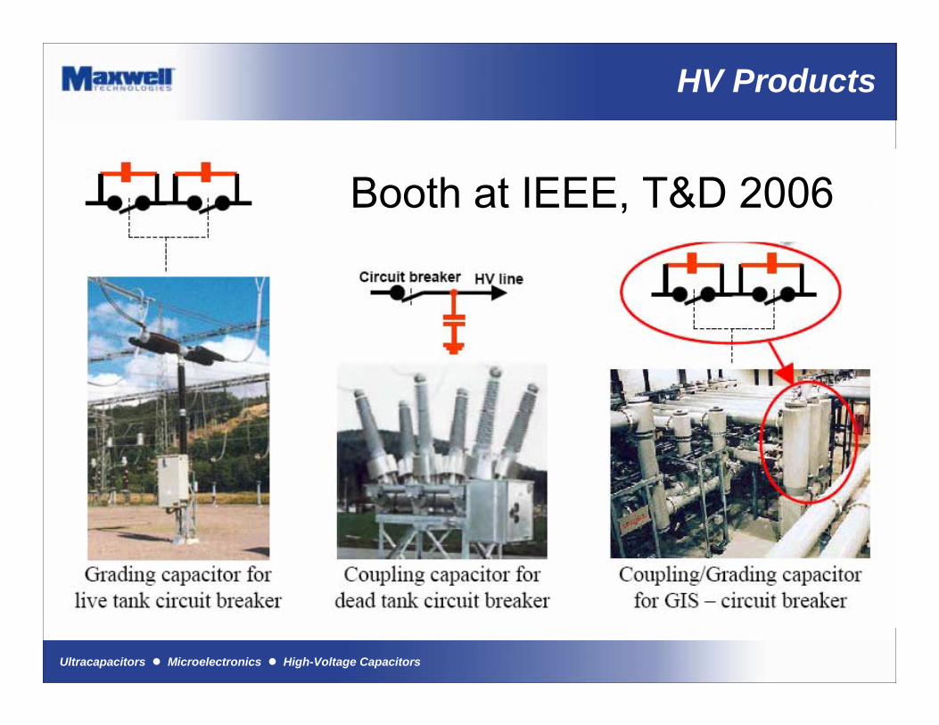
HV Products
Booth at IEEE, T&D 2006
Ultracapacitors ! Microelectronics ! High-Voltage Capacitors
Useful Links
� Useful links on Maxwell Technologies Web-site:� White Papers� Technology Overview� Sizing worksheet� Application Notes� Data Sheets� Product Guide
www.maxwell.com

Ultracapacitors ! Microelectronics ! High-Voltage Capacitors
Contact Information
John Dispennette
Application Engineer
919 847 3073


![Automotive Market Perspective of Ultracapacitors[1]](https://img.pdfslide.us/doc/110x75/577d244a1a28ab4e1e9c1aa5/automotive-market-perspective-of-ultracapacitors1.jpg)