Embed Size (px)
Citation preview

ZEBRA plus ultracapacitors: A good match for energy efficient EVs
Juan Dixon, Micah Ortúzar, Eduardo Arcos and Ian Nakashima.
Abstract
ZEBRA batteries have demonstrated mature development, having reached almost 120 Wh/kg specific energy. On the other hand, specific power has a good figure, but needs to be improved for fast acceleration and good regenerative braking. With this purpose in mind, an ultra capacitor power system is being included in an EV that uses a high temperature Sodium-Nickel Chloride battery (ZEBRA). The ultra capacitor system has been connected to the ZEBRA battery and to the traction inverter through a Buck-Boost type DC-DC converter, which manages the energy flow with the help of DSP controller. Special control algorithms are being programmed for such a purpose. The paper shows the implementation of the experimental vehicle with the location of all components, and some simulation of the vehicle operation. Previous experimental results with lead-acid batteries demonstrated excellent behavior and now, the tests with the ZEBRA battery are under way.
Keywords: ultra capacitor, Sodium-Nickel-Chloride, control system.
1 Introduction Ultra capacitors [1] are a very good solution for hybrid electric vehicles. However, they can also be useful for pure electric vehicles that use batteries with low specific power (W/kg). Those kinds of batteries show reduced acceleration and reduced regenerative braking capability. One example of this kind is the Sodium Nickel-Chloride (ZEBRA) battery, which has excellent specific energy, only compared with lithium based batteries. This battery also has a very large cycle life (more than 1000 cycles), good temperature stability, excellent efficiency, and the capability of being discharged almost 100%. The low specific power characteristic of the ZEBRA battery is compared with other typical batteries used in EVs in figure 1. As can be observed, the ZEBRA does not have a good specific power for braking and acceleration [2]. To improve this characteristic, a combined system with ultra capacitors is being implemented.
Specific Power (W/Kg)
0
100
200
300
400
Lead-Acid Li-Ion Lithium Polymer
Ni-MH Ni-Cd ZEBRA Na-S
Figure 1: specific power comparison between the most common secondary batteries for EVs.
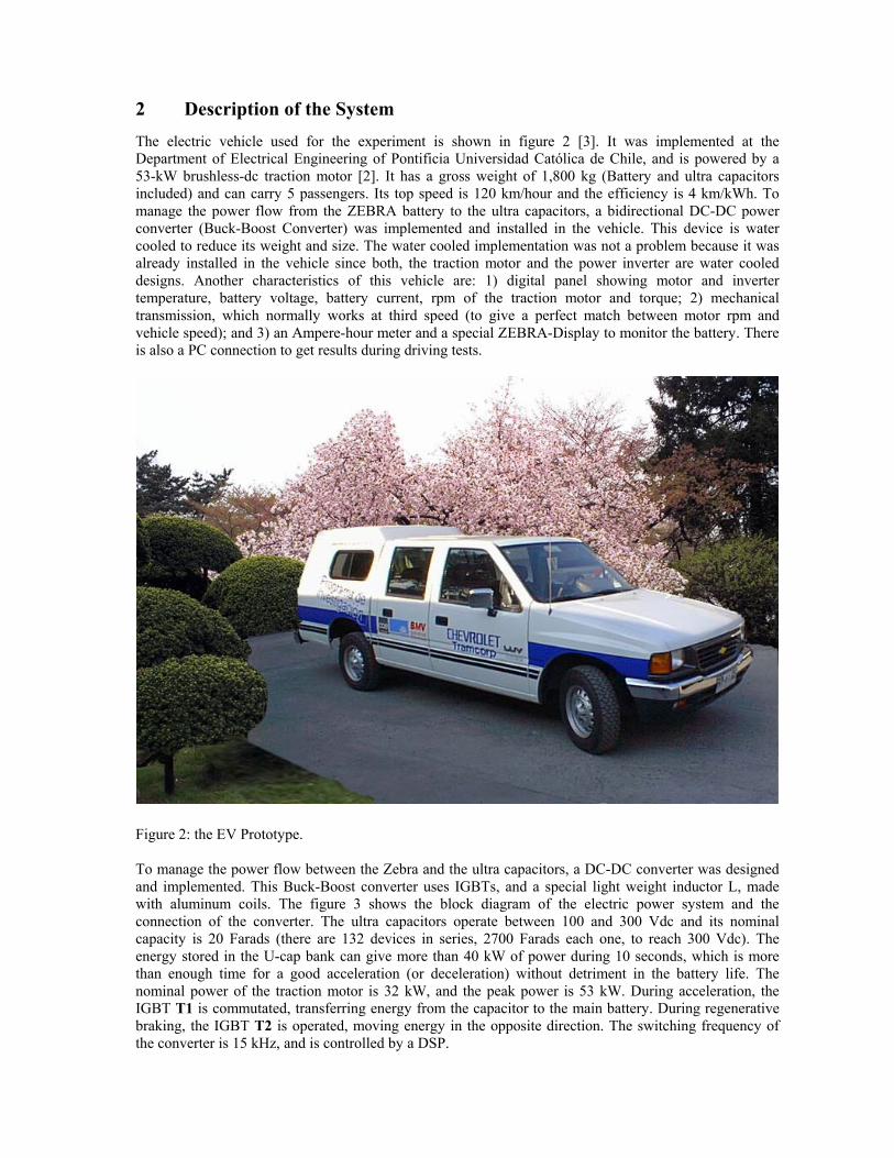
2 Description of the System The electric vehicle used for the experiment is shown in figure 2 [3]. It was implemented at the Department of Electrical Engineering of Pontificia Universidad Católica de Chile, and is powered by a 53-kW brushless-dc traction motor [2]. It has a gross weight of 1,800 kg (Battery and ultra capacitors included) and can carry 5 passengers. Its top speed is 120 km/hour and the efficiency is 4 km/kWh. To manage the power flow from the ZEBRA battery to the ultra capacitors, a bidirectional DC-DC power converter (Buck-Boost Converter) was implemented and installed in the vehicle. This device is water cooled to reduce its weight and size. The water cooled implementation was not a problem because it was already installed in the vehicle since both, the traction motor and the power inverter are water cooled designs. Another characteristics of this vehicle are: 1) digital panel showing motor and inverter temperature, battery voltage, battery current, rpm of the traction motor and torque; 2) mechanical transmission, which normally works at third speed (to give a perfect match between motor rpm and vehicle speed); and 3) an Ampere-hour meter and a special ZEBRA-Display to monitor the battery. There is also a PC connection to get results during driving tests.
Figure 2: the EV Prototype.
To manage the power flow between the Zebra and the ultra capacitors, a DC-DC converter was designed and implemented. This Buck-Boost converter uses IGBTs, and a special light weight inductor L, made with aluminum coils. The figure 3 shows the block diagram of the electric power system and the connection of the converter. The ultra capacitors operate between 100 and 300 Vdc and its nominal capacity is 20 Farads (there are 132 devices in series, 2700 Farads each one, to reach 300 Vdc). The energy stored in the U-cap bank can give more than 40 kW of power during 10 seconds, which is more than enough time for a good acceleration (or deceleration) without detriment in the battery life. The nominal power of the traction motor is 32 kW, and the peak power is 53 kW. During acceleration, the IGBT T1 is commutated, transferring energy from the capacitor to the main battery. During regenerative braking, the IGBT T2 is operated, moving energy in the opposite direction. The switching frequency of the converter is 15 kHz, and is controlled by a DSP.

Buck-Boost Converter
Buck
Boost T1 D1
T2 D2
L
CV CAP
20 Farads ULTRA
CAPACITOR BANK
(132 ultra capacitors in
series)
+
_
+
371 Vdc BATTERY
PACK
+
_
I LOAD
I BATT
ICOMP
I CAP
POWER INVERTER
FOR TRACTION
MOTOR
ZEBRA Battery
Z36-371
ML3P-76
Figure 3: block diagram of the power system to manage the energy flow into the vehicle
3 Physical location of components The diagram of Figure 4 shows the location of each one of the main power components of the vehicle, and the next paragraphs show some pictures of these devices.
Figure 4: physical location of each main power component into the EV.
3.1 The Ultra Capacitor and Power Inductor. Part of the U-cap bank is in front of the vehicle (two boxes), and three more boxes are at the rear of the vehicle, under the floor, in an aluminum case protection. The figure 5 shows the location of the first two U-caps boxes (only one is visible because the other one is at the bottom). This figure also shows the Buck-Boost converter, which is uncovered to see the power components. The U-caps located at the rear are shown in Figure 6.

Figure 5: Ultra capacitor bank and Buck-Boost converter in front of the vehicle.
Figure 6: Ultra capacitor bank at the rear, under the floor.
Buck-Boost Converter (without the cover)
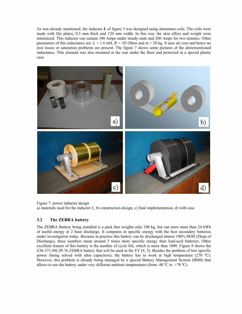
As was already mentioned, the inductor L of figure 3 was designed using aluminum coils. The coils were made with flat plates, 0.5 mm thick and 120 mm width. In this way the skin effect and weight were minimized. This inductor can sustain 100 Amps under steady-state and 200 Amps for two minutes. Other parameters of this inductance are: L = 1.6 mH, R = .03 Ohms and m = 20 kg. It uses air core and hence no iron losses or saturation problems are present. The figure 7 shows some pictures of the aforementioned inductance. This element was also mounted at the rear under the floor and protected in a special plastic case.
Figure 7: power inductor design a) materials used for the inductor L, b) construction design, c) final implementation, d) with case
3.2 The ZEBRA battery The ZEBRA Battery being installed is a pack that weights only 240 kg, but can store more than 24 kWh of useful energy at 2 hour discharge. It compares in specific energy with the best secondary batteries under investigation today. Because in practice this battery can be discharged almost 100% DOD (Deep of Discharge), these numbers mean around 5 times more specific energy than lead-acid batteries. Other excellent feature of this battery is the number of cycle life, which is more than 1000. Figure 8 shows the Z36-371-ML3P-76 ZEBRA battery that will be used in the EV [4, 5]. Besides the problem of low specific power (being solved with ultra capacitors), the battery has to work at high temperature (270 ºC). However, this problem is already being managed by a special Battery Management System (BMS) that allows to use the battery under very different ambient temperatures (from -40 ºC to +70 ºC).

Figure 8: ZEBRA battery type Z36-371-ML3P-76 being installed at the rear of the vehicle.
3.3 Control System. Figure 9 shows the control board of the ZEBRA-Ultracapacitor (Ucap) system. This control board was implemented in a TMS320F241 DSP from Texas Instruments. Also a monitoring feature was implemented in the DSP, which communicates with a portable PC. The monitoring program at the PC allows real time plotting and storing all valuable data; also the Control program at the DSP can be commanded from the PC to work in slave mode (user controlled currents) or automated mode [7].
Figure 9: DSP control circuit board and connectors.
The figure 10 shows the block diagram of the DSP controller. Signals required to perform algorithm calculations are: ZEBRA battery voltage, battery current, drive train current, ultra capacitor bank voltage, ultra capacitor bank current, DC-DC (Buck-Boost) converter temperature, battery state of charge and

vehicle speed. Some of these signals are available from the main inverter microprocessor, which are sent in analog format; the rest of the signals are acquired from specially installed sensors and an Ah counter installed in the vehicle. The control System final products are two PWM signals, which commutates the two IGBT’s in the Buck-Boost DC-DC converter. The PWM values are calculated as part of a closed loop PI control, comparing a preset current reference and the measured current from the DC-DC converter. The power transfer algorithm calculates the preset current value for the current control, considering the battery state of charge, the battery voltage, the ultra capacitor charge; the vehicle’s speed and the power drive system current.
Gating Signals
DigitalSignal
ProcessorTMS320F241
Motor Controlµ
ProcessorEVPH 332
Buck-Boost
Converter
SerialComm.Data
PWM
Sensors:•Current•Voltage •Temp.
AhCounter
Figure 10: control system layout
4 Simulation of the Overall System
Simulations of the system are still under way, but they promise positive results in the final tests of the vehicle being tested next March 2005. The simulation in Figure 11 shows a simulation of the ZEBRA battery at 80% DOD, during acceleration of the vehicle from 40 to 60 km/h in 4 seconds. Ultra capacitors are not connected and it can be seen that the battery voltage is strongly affected by the current variations. A serious problem arises when battery has to supply more than 150 Amps, because in this case the voltage drops to values smaller than 250 Vdc. Under these conditions the control of the traction motor reset the PWM of the inverter because of under voltage operation, and the current can’t go higher (the simulation however, shows a condition in which the current still can increase and the voltage remains unknown, because in fact the vehicle cannot work under these conditions). Similar behavior is observed under 10% and 50% DOD, and it is nor worth to repeat the graphics.
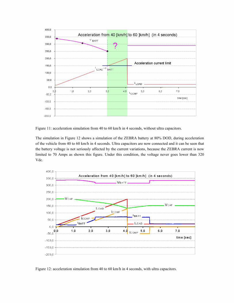
Figure 11: acceleration simulation from 40 to 60 km/h in 4 seconds, without ultra capacitors.
The simulation in Figure 12 shows a simulation of the ZEBRA battery at 80% DOD, during acceleration of the vehicle from 40 to 60 km/h in 4 seconds. Ultra capacitors are now connected and it can be seen that the battery voltage is not seriously affected by the current variations, because the ZEBRA current is now limited to 70 Amps as shown this figure. Under this condition, the voltage never goes lower than 320 Vdc.
Figure 12: acceleration simulation from 40 to 60 km/h in 4 seconds, with ultra capacitors.

The simulation in Figure 13 shows now a simulation of the ZEBRA during regenerative braking of the vehicle from 40 to 0 km/h in 2.1 seconds. Ultra capacitors are not connected and it can be seen that the battery voltage goes higher than 400 Vdc when the current reaches around -40 Adc. Under these conditions the control of the traction motor reset the PWM of the inverter because of over voltage operation (more than 400 Vdc), and the current can’t go higher (the simulation however, shows a condition in which the current still can go to more negative values and the voltage remains unknown, because in fact the vehicle cannot work under these conditions).
Figure 13: regenerative braking simulation from 40 to stop in 2.1 seconds, without ultra capacitors.
Finally, the simulation in Figure 13 shows again the ZEBRA during regenerative braking from 40 to 0 km/h in 2.1 seconds. Ultra capacitors are now connected and it can be seen that the battery voltage never goes higher than 400 Vdc because most of the current is now supplied by the ultra capacitors. In this case, the regenerative braking works well because ultra capacitors take care of the currents, avoiding battery voltage to go higher than 400 Vdc. It is important to mention that the control system can be programmed according with the characteristics of the system. In this case, two important limits have to be respected: the under voltage of 250 Vdc, and the over voltage of 400 Vdc. It is also worth to mention that regenerative braking with only ultra capacitors do not work in large down hills, because they finally will reach their maximum voltage, being unable to receive more energy. Under these conditions, the regenerative braking has to be limited to the capacity of the ZEBRA to receive power without reaching the voltage limit (400 Vdc). Other solution is to add power resistors for this situation.

Figure 14: regenerative braking simulation from 40 to stop in 2.1 seconds, with ultra capacitors.
5 Conclusions
The implementation of a power drive for an electric vehicle, based on Sodium Nickel-Chloride battery and ultra capacitors has been described. The main idea is to improve the performance of the battery, due its low specific power compared with other traction batteries. The paper shows the way each component of the system is located, how some of them have been implemented, and what kind of control is being used. Finally, simulations show the positive behavior of the system, which is in its last stage of construction for tests in the near weeks.
6 Acknowledgments The authors want to thank Conicyt through the project Fondecyt N° 1020982, for the financial support given to this work.
7 References
[1] Maxwell. Ultracapacitors Data sheets and technical information for 1,000 and 2,500 Farads, [Maxwell publications]
[2] C. C. Chan and Y. S. Wong, Electric Vehicles Charge Forward, IEEE Power and Energy Magazine, Vol.2, Nº6, Nov-Dec. 2004, pp24-33.
[3] Juan Dixon, Micah Ortúzar, Raúl Schmidt, Gerardo Lazo, Iván Leal, Felipe García, Matías Rodríguez, Alejandro Amaro and Eduardo Wiechmann, Performance Characteristics of the First, State-of-the-art Electric Vehicle Implemented in Chile, EVS17, Montreal, Canada, October 2000.
[4] MES-DEA, ZEBRA Batteries Technical information for Z36-371-ML3P-76 type. Rev 02 del 05.04.04. [5] C.-H. Dustmann, AEG ZEBRA Battery Marketing GmbH, ‘ZEBRA Powered Public Transportation
Experience’, September 1, 1998.

[6] A. F. Burke, Electrochemical Capacitors for Electric Vehicles. Technology Update and Implementation Considerations, University of California at Davis, EVS-12 Symposium Proceedings, pp.27-36, 1996.
[7] Juan W. Dixon, Micah Ortúzar and Jorge Moreno, Monitoring System for Testing the Performance of an Electric Vehicle Using Ultracapacitors, Electric Vehicle Symposium, EVS19, Busan, Corea, October 2002
Authors
Juan W. Dixon, Department of Electrical Engineering, Pontificia Universidad Católica deChile, Casilla 306, Correo 22, Santiago, Chile; Phone 56-2-686-4281, Fax 56-2-552-2563,E-mail: [email protected] J. Dixon got the Ph.D. degree from McGill University, Montreal, Canada; From 1977 to1979 he was with the National Railways Company (Ferrocarriles del Estado). Since 1979he is Professor at the Pontificia Universidad Católica de Chile. His main research interestsare power rectifiers, multilevel converters, active power filters, machine drives, electrictraction and electric vehicles.
Micah E. Ortúzar, Department of Electrical Engineering, Pontificia Universidad Católicade Chile, Casilla 306, Correo 22, Santiago, Chile; Phone 56-2-686-4223, Fax 56-2-552-2563, E-mail: [email protected] M. Ortúzar got his Electrical Engineering degree from Pontificia Universidad Católica deChile. He has worked in power active filters, power electronics and electric vehiclesresearch projects. At the moment M. Ortúzar is working towards the Ph.D. degree fromPontificia Universidad Católica de Chile, Santiago, Chile;
Eduardo F. Arcos, Department of Electrical Engineering, Pontificia Universidad Católicade Chile, Casilla 306, Correo 22, Santiago, Chile; Phone 56-2-686-4223, Fax 56-2-552-2563, E-mail: [email protected] E. Arcos is working towards the Ms.C. degree from Pontificia Universidad Católica deChile, Santiago, Chile; he Also works in R&D in Dreamline Power Solution.
Ian Nakashima, Department of Electrical Engineering, Pontificia Universidad Católica deChile, Casilla 306, Correo 22, Santiago, Chile; Phone 56-2-686-4223, Fax 56-2-552-2563,E-mail: [email protected] Ian Nakashima is working towards the Electrical Engineer Professional degree fromPontificia Universidad Católica de Chile, Santiago, Chile;


![Automotive Market Perspective of Ultracapacitors[1]](https://img.pdfslide.us/doc/110x75/577d244a1a28ab4e1e9c1aa5/automotive-market-perspective-of-ultracapacitors1.jpg)