Embed Size (px)
Citation preview
Gasoline-Electric
Hybrid Synergy Drive
Revised
ZWE186 Series
ii
Foreword
This guide was developed to educate and assist dismantlers in the safe handling of Toyota AURIS
Hybrid gasoline-electric hybrid vehicles. AURIS Hybrid dismantling procedures are similar to other
non-hybrid Toyota vehicles with the exception of the high voltage electrical system. It is important to
recognize and understand the high voltage electrical system features and specifications of the Toyota
AURIS Hybrid, as they may not be familiar to dismantlers.
High voltage electricity powers the electric motor, generator, Air Conditioning (A/C) compressor and
inverter/converter. All other automotive electrical devices such as the head lights, radio, and gauges
are powered from a separate 12 Volt auxiliary battery. Numerous safeguards have been designed into
the AURIS Hybrid to help ensure the high voltage, approximately 201.6 Volt, Nickel Metal Hydride
(NiMH) Hybrid Vehicle (HV) battery pack is kept safe and secure in an accident.
The NiMH HV battery pack contains sealed batteries that are similar to rechargeable batteries used in
some battery operated power tools and other consumer products. The electrolyte is absorbed in the cell
plates and will not normally leak out even if the battery is cracked. In the unlikely event the electrolyte
does leak, it can be easily neutralized with a dilute boric acid solution or vinegar.
High voltage cables, identifiable by orange insulation and connectors, are isolated from the metal chassis
of the vehicle.
Additional topics contained in the guide include:
• Toyota AURIS Hybrid identification.
• Major hybrid component locations and descriptions.
By following the information in this guide, dismantlers will be able to handle AURIS Hybrid
hybrid-electric vehicles as safely as the dismantling of a conventional gasoline engine automobile.
2013 Toyota Motor Corporation All rights reserved. This book may not be reproduced or copied, in whole or in part, without the written permission of Toyota Motor Corporation.
iii
Table of Contents
About the AURIS Hybrid ......................................................................................................................... 1
AURIS Hybrid Identification ................................................................................................................... 2 Exterior ......................................................................................................................................................... 3 Interior ........................................................................................................................................................... 5 Engine Compartment .................................................................................................................................... 6
Hybrid Component Locations & Descriptions ........................................................................................ 7 Specifications ................................................................................................................................................ 8
Hybrid Synergy Drive Operation ............................................................................................................. 9 Vehicle Operation .......................................................................................................................................... 9
Hybrid Vehicle (HV) Battery Pack and Auxiliary Battery ................................................................... 10 HV Battery Pack .......................................................................................................................................... 10 Components Powered by the HV Battery Pack ........................................................................................... 10 HV Battery Pack Recycling ......................................................................................................................... 11 Auxiliary Battery .......................................................................................................................................... 11
High Voltage Safety ................................................................................................................................. 12 High Voltage Safety System........................................................................................................................ 12 Service Plug Grip ........................................................................................................................................ 13
Precaution to be observed when dismantling the vehicle ..................................................................... 14 Necessary Items ......................................................................................................................................... 14
Spills .......................................................................................................................................................... 15
Dismantling a vehicle............................................................................................................................... 16
Removal of HV battery ........................................................................................................................... 19 HV Battery Caution Label ........................................................................................................................... 28

1
About the AURIS Hybrid The AURIS Hybrid 5-door hatchback and 5-door wagon joins the PRIUS, PRIUS c, PRIUS +/PRIUS v, and YARIS Hybrid as a hybrid model for Toyota. Hybrid Synergy Drive means that the vehicle contains a gasoline engine and an electric motor for power. The two hybrid power sources are stored on board the vehicle:
1. Gasoline stored in the fuel tank for the gasoline engine. 2. Electricity stored in a high voltage Hybrid Vehicle (HV) battery pack for the
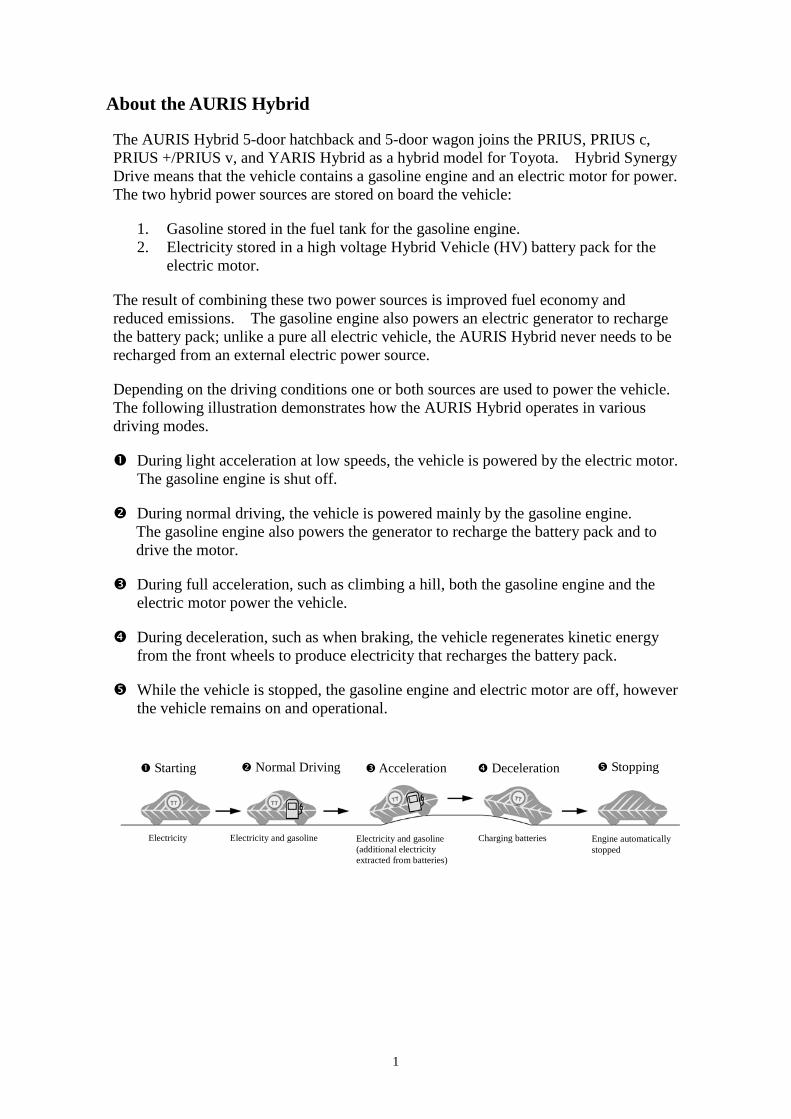
electric motor. The result of combining these two power sources is improved fuel economy and reduced emissions. The gasoline engine also powers an electric generator to recharge the battery pack; unlike a pure all electric vehicle, the AURIS Hybrid never needs to be recharged from an external electric power source. Depending on the driving conditions one or both sources are used to power the vehicle. The following illustration demonstrates how the AURIS Hybrid operates in various driving modes. During light acceleration at low speeds, the vehicle is powered by the electric motor.
The gasoline engine is shut off. During normal driving, the vehicle is powered mainly by the gasoline engine.
The gasoline engine also powers the generator to recharge the battery pack and to drive the motor.
During full acceleration, such as climbing a hill, both the gasoline engine and the
electric motor power the vehicle. During deceleration, such as when braking, the vehicle regenerates kinetic energy
from the front wheels to produce electricity that recharges the battery pack. While the vehicle is stopped, the gasoline engine and electric motor are off, however
the vehicle remains on and operational.
Starting Normal Driving Acceleration Deceleration Stopping
Electricity Electricity and gasoline Electricity and gasoline (additional electricity extracted from batteries)
Charging batteries Engine automatically stopped
2
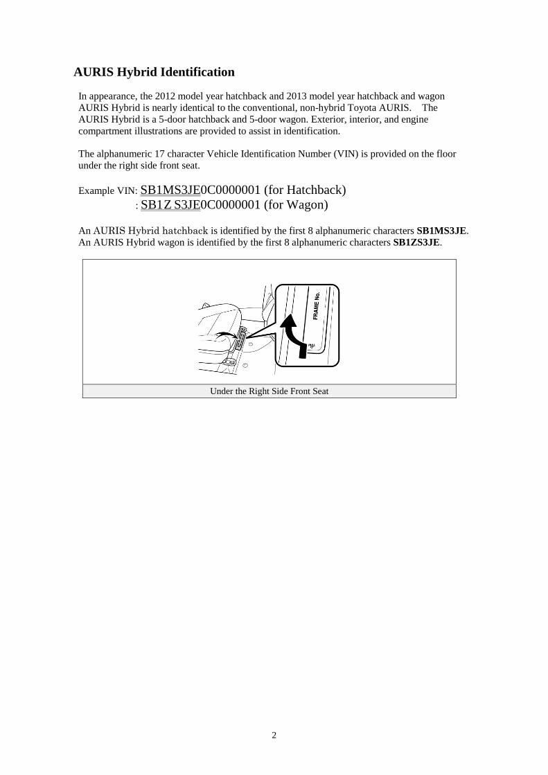
AURIS Hybrid Identification In appearance, the 2012 model year hatchback and 2013 model year hatchback and wagon AURIS Hybrid is nearly identical to the conventional, non-hybrid Toyota AURIS. The AURIS Hybrid is a 5-door hatchback and 5-door wagon. Exterior, interior, and engine compartment illustrations are provided to assist in identification. The alphanumeric 17 character Vehicle Identification Number (VIN) is provided on the floor under the right side front seat. Example VIN: SB1MS3JE0C0000001 (for Hatchback)
: SB1Z S3JE0C0000001 (for Wagon) An AURIS Hybrid hatchback is identified by the first 8 alphanumeric characters SB1MS3JE. An AURIS Hybrid wagon is identified by the first 8 alphanumeric characters SB1ZS3JE.
Under the Right Side Front Seat
3
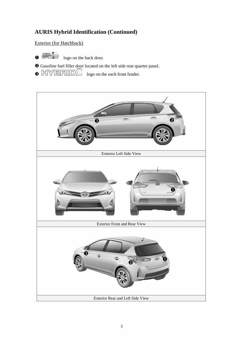
AURIS Hybrid Identification (Continued) Exterior (for Hatchback)
logo on the back door.
Gasoline fuel filler door located on the left side rear quarter panel.
logo on the each front fender.
Exterior Left Side View
Exterior Front and Rear View
Exterior Rear and Left Side View
4
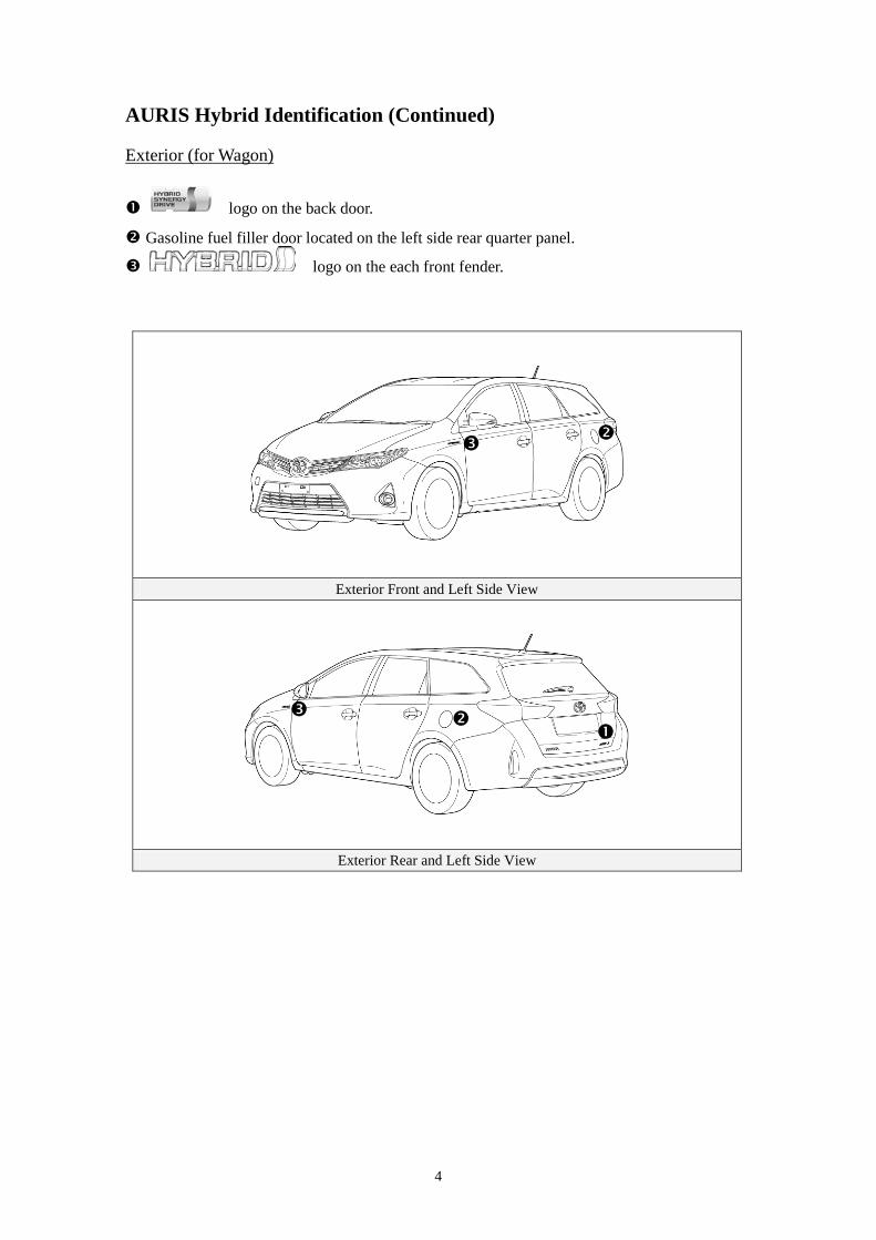
AURIS Hybrid Identification (Continued) Exterior (for Wagon)
logo on the back door.
Gasoline fuel filler door located on the left side rear quarter panel. logo on the each front fender.
Exterior Front and Left Side View
Exterior Rear and Left Side View
5
AURIS Hybrid Identification (Continued)
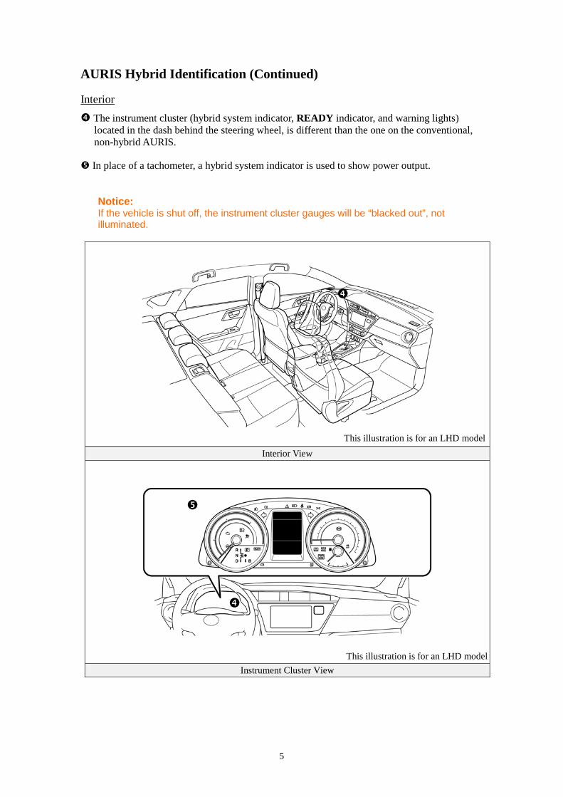
The instrument cluster (hybrid system indicator, READY indicator, and warning lights) located in the dash behind the steering wheel, is different than the one on the conventional, non-hybrid AURIS.
Interior
In place of a tachometer, a hybrid system indicator is used to show power output.
Notice: If the vehicle is shut off, the instrument cluster gauges will be “blacked out”, not illuminated.
Interior View
Instrument Cluster View
This illustration is for an LHD model
This illustration is for an LHD model
6
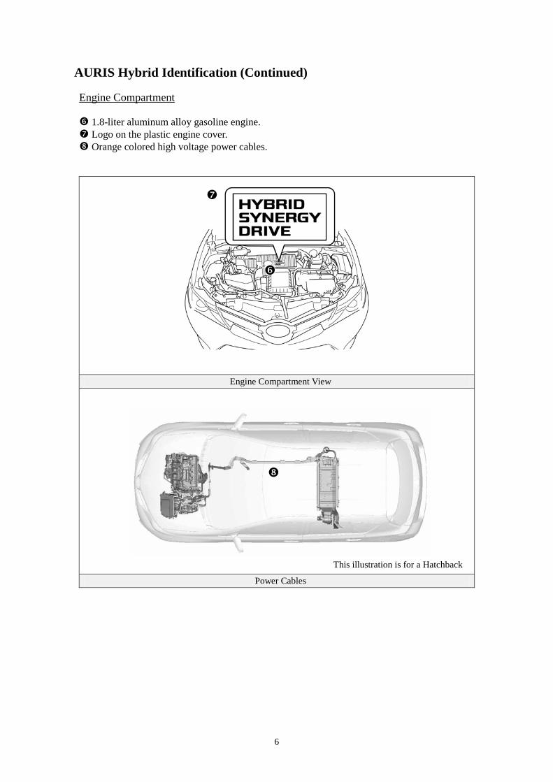
AURIS Hybrid Identification (Continued) Engine Compartment 1.8-liter aluminum alloy gasoline engine. Logo on the plastic engine cover. Orange colored high voltage power cables.
Engine Compartment View
Power Cables
This illustration is for a Hatchback
7
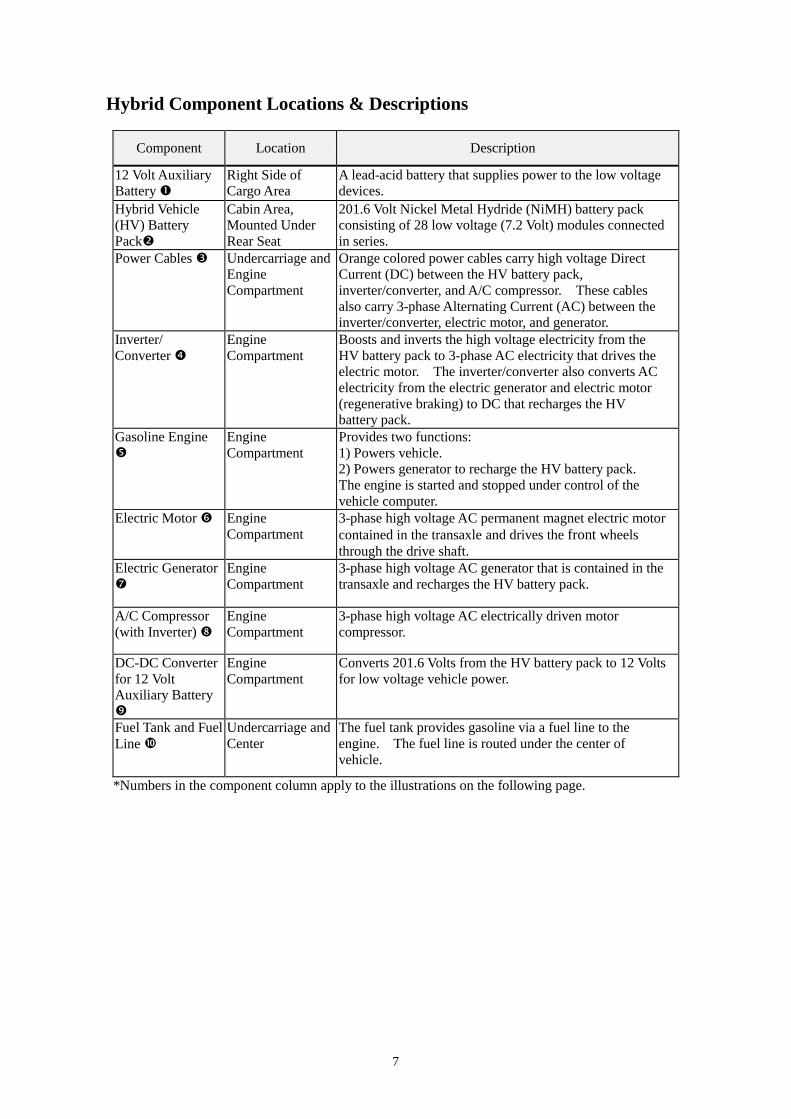
Hybrid Component Locations & Descriptions
Component Location Description
12 Volt Auxiliary Battery
Right Side of Cargo Area
A lead-acid battery that supplies power to the low voltage devices.
Hybrid Vehicle (HV) Battery Pack
Cabin Area, Mounted Under Rear Seat
201.6 Volt Nickel Metal Hydride (NiMH) battery pack consisting of 28 low voltage (7.2 Volt) modules connected in series.
Power Cables Undercarriage and Engine Compartment
Orange colored power cables carry high voltage Direct Current (DC) between the HV battery pack, inverter/converter, and A/C compressor. These cables also carry 3-phase Alternating Current (AC) between the inverter/converter, electric motor, and generator.
Inverter/ Converter
Engine Compartment
Boosts and inverts the high voltage electricity from the HV battery pack to 3-phase AC electricity that drives the electric motor. The inverter/converter also converts AC electricity from the electric generator and electric motor (regenerative braking) to DC that recharges the HV battery pack.
Gasoline Engine
Engine Compartment
Provides two functions: 1) Powers vehicle. 2) Powers generator to recharge the HV battery pack. The engine is started and stopped under control of the vehicle computer.
Electric Motor Engine Compartment
3-phase high voltage AC permanent magnet electric motor contained in the transaxle and drives the front wheels through the drive shaft.
Electric Generator
Engine Compartment
3-phase high voltage AC generator that is contained in the transaxle and recharges the HV battery pack.
A/C Compressor (with Inverter)
Engine Compartment
3-phase high voltage AC electrically driven motor compressor.
DC-DC Converter for 12 Volt Auxiliary Battery
Engine Compartment
Converts 201.6 Volts from the HV battery pack to 12 Volts for low voltage vehicle power.
Fuel Tank and Fuel Line
Undercarriage and Center
The fuel tank provides gasoline via a fuel line to the engine. The fuel line is routed under the center of vehicle.
*Numbers in the component column apply to the illustrations on the following page.
8
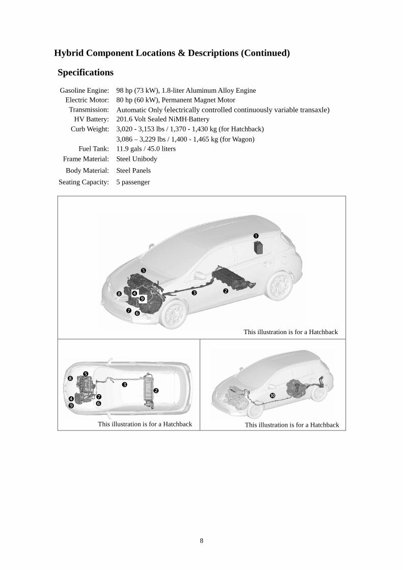
Hybrid Component Locations & Descriptions (Continued) Specifications Gasoline Engine: 98 hp (73 kW), 1.8-liter Aluminum Alloy Engine
Electric Motor: 80 hp (60 kW), Permanent Magnet Motor Transmission: Automatic Only (electrically controlled continuously variable transaxle)
HV Battery: 201.6 Volt Sealed NiMH Battery Curb Weight: 3,020 - 3,153 lbs / 1,370 - 1,430 kg (for Hatchback)
3,086 – 3,229 lbs / 1,400 - 1,465 kg (for Wagon) Fuel Tank: 11.9 gals / 45.0 liters
Frame Material: Steel Unibody Body Material: Steel Panels
Seating Capacity: 5 passenger
This illustration is for a Hatchback
This illustration is for a Hatchback
This illustration is for a Hatchback
9
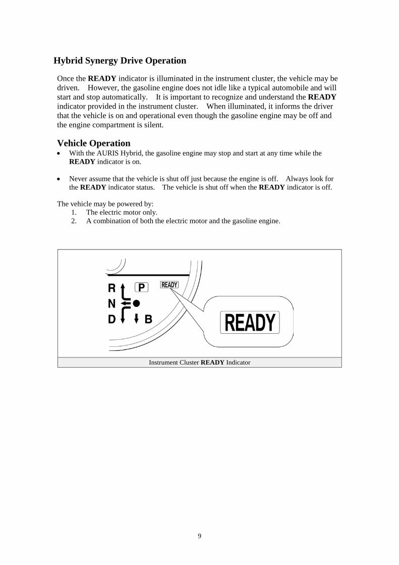
Hybrid Synergy Drive Operation Once the READY indicator is illuminated in the instrument cluster, the vehicle may be driven. However, the gasoline engine does not idle like a typical automobile and will start and stop automatically. It is important to recognize and understand the READY indicator provided in the instrument cluster. When illuminated, it informs the driver that the vehicle is on and operational even though the gasoline engine may be off and the engine compartment is silent. Vehicle Operation • With the AURIS Hybrid, the gasoline engine may stop and start at any time while the
READY indicator is on. • Never assume that the vehicle is shut off just because the engine is off. Always look for
the READY indicator status. The vehicle is shut off when the READY indicator is off. The vehicle may be powered by:
1. The electric motor only. 2. A combination of both the electric motor and the gasoline engine.
Instrument Cluster READY Indicator
10
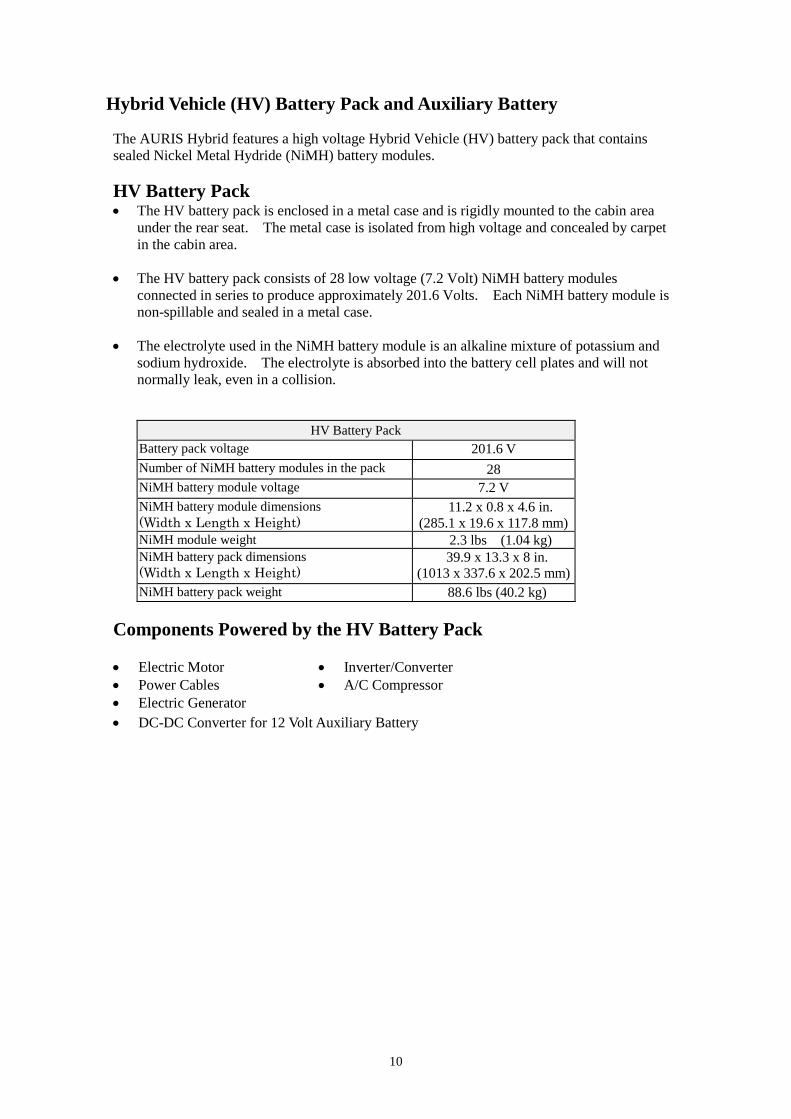
Hybrid Vehicle (HV) Battery Pack and Auxiliary Battery The AURIS Hybrid features a high voltage Hybrid Vehicle (HV) battery pack that contains sealed Nickel Metal Hydride (NiMH) battery modules. HV Battery Pack • The HV battery pack is enclosed in a metal case and is rigidly mounted to the cabin area
under the rear seat. The metal case is isolated from high voltage and concealed by carpet in the cabin area.
• The HV battery pack consists of 28 low voltage (7.2 Volt) NiMH battery modules
connected in series to produce approximately 201.6 Volts. Each NiMH battery module is non-spillable and sealed in a metal case.
• The electrolyte used in the NiMH battery module is an alkaline mixture of potassium and
sodium hydroxide. The electrolyte is absorbed into the battery cell plates and will not normally leak, even in a collision.
HV Battery Pack Battery pack voltage 201.6 V Number of NiMH battery modules in the pack 28 NiMH battery module voltage 7.2 V NiMH battery module dimensions (Width x Length x Height)
11.2 x 0.8 x 4.6 in. (285.1 x 19.6 x 117.8 mm)
NiMH module weight 2.3 lbs (1.04 kg) NiMH battery pack dimensions (Width x Length x Height)
39.9 x 13.3 x 8 in. (1013 x 337.6 x 202.5 mm)
NiMH battery pack weight 88.6 lbs (40.2 kg) Components Powered by the HV Battery Pack
• Electric Motor • Inverter/Converter • Power Cables • A/C Compressor • Electric Generator • DC-DC Converter for 12 Volt Auxiliary Battery
11
Hybrid Vehicle (HV) Battery Pack and Auxiliary Battery (Continued) HV Battery Pack Recycling • The HV battery pack is recyclable. Contact either your Toyota distributor as mentioned on
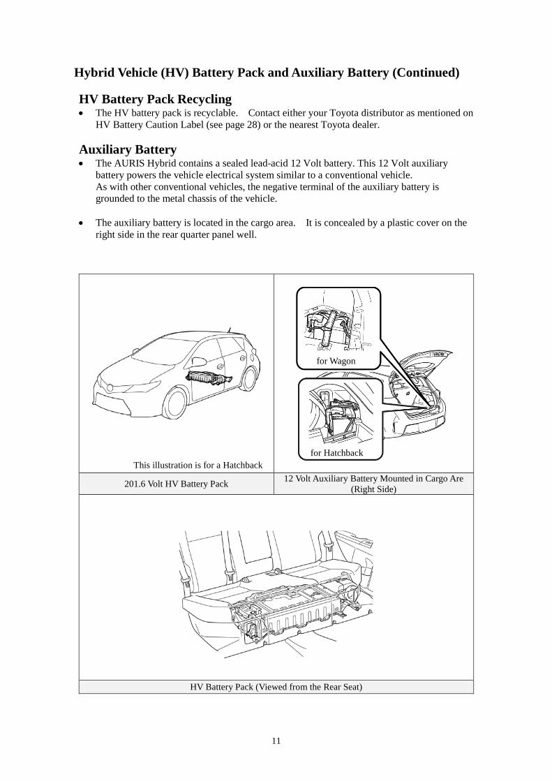
HV Battery Caution Label (see page 28) or the nearest Toyota dealer. Auxiliary Battery • The AURIS Hybrid contains a sealed lead-acid 12 Volt battery. This 12 Volt auxiliary
battery powers the vehicle electrical system similar to a conventional vehicle. As with other conventional vehicles, the negative terminal of the auxiliary battery is grounded to the metal chassis of the vehicle.
• The auxiliary battery is located in the cargo area. It is concealed by a plastic cover on the
right side in the rear quarter panel well.
201.6 Volt HV Battery Pack 12 Volt Auxiliary Battery Mounted in Cargo Are (Right Side)
HV Battery Pack (Viewed from the Rear Seat)
for Wagon
for Hatchback This illustration is for a Hatchback
12
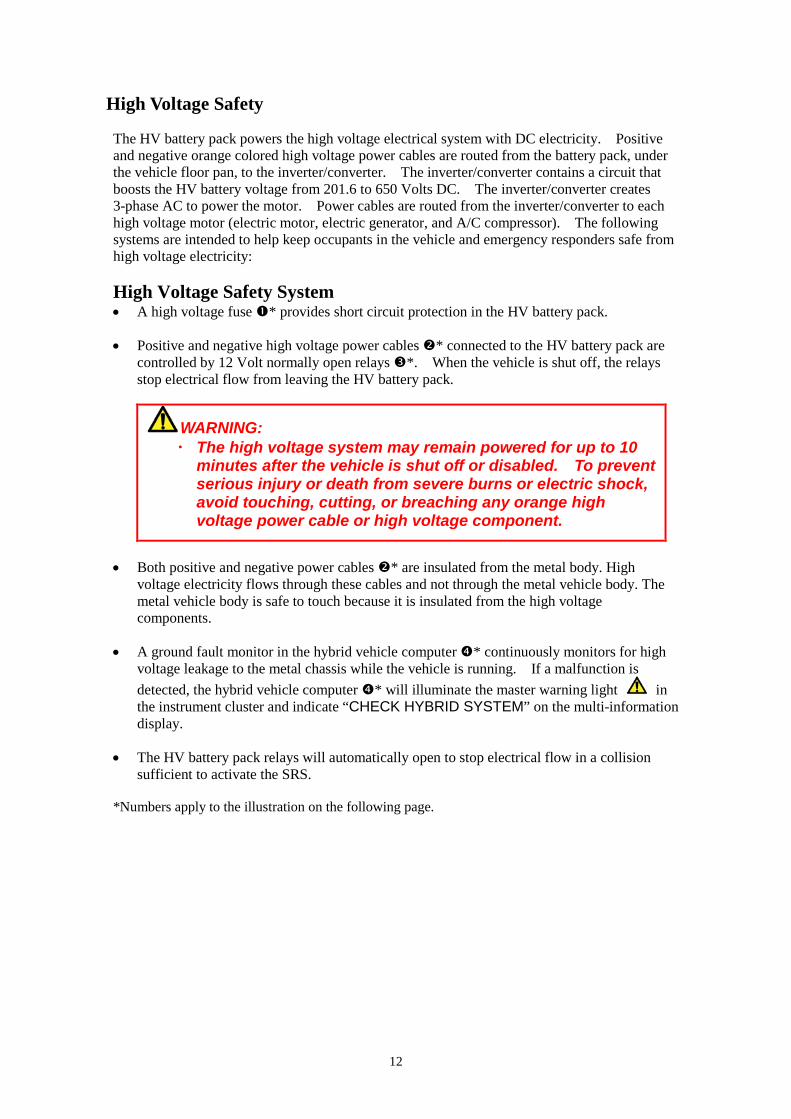
High Voltage Safety The HV battery pack powers the high voltage electrical system with DC electricity. Positive and negative orange colored high voltage power cables are routed from the battery pack, under the vehicle floor pan, to the inverter/converter. The inverter/converter contains a circuit that boosts the HV battery voltage from 201.6 to 650 Volts DC. The inverter/converter creates 3-phase AC to power the motor. Power cables are routed from the inverter/converter to each high voltage motor (electric motor, electric generator, and A/C compressor). The following systems are intended to help keep occupants in the vehicle and emergency responders safe from high voltage electricity: High Voltage Safety System • A high voltage fuse * provides short circuit protection in the HV battery pack. • Positive and negative high voltage power cables * connected to the HV battery pack are
controlled by 12 Volt normally open relays *. When the vehicle is shut off, the relays stop electrical flow from leaving the HV battery pack.
WARNING: ・ The high voltage system may remain powered for up to 10
minutes after the vehicle is shut off or disabled. To prevent serious injury or death from severe burns or electric shock, avoid touching, cutting, or breaching any orange high voltage power cable or high voltage component.
• Both positive and negative power cables * are insulated from the metal body. High
voltage electricity flows through these cables and not through the metal vehicle body. The metal vehicle body is safe to touch because it is insulated from the high voltage components.
• A ground fault monitor in the hybrid vehicle computer * continuously monitors for high
voltage leakage to the metal chassis while the vehicle is running. If a malfunction is detected, the hybrid vehicle computer * will illuminate the master warning light in the instrument cluster and indicate “CHECK HYBRID SYSTEM” on the multi-information display.
• The HV battery pack relays will automatically open to stop electrical flow in a collision
sufficient to activate the SRS. *Numbers apply to the illustration on the following page.
13
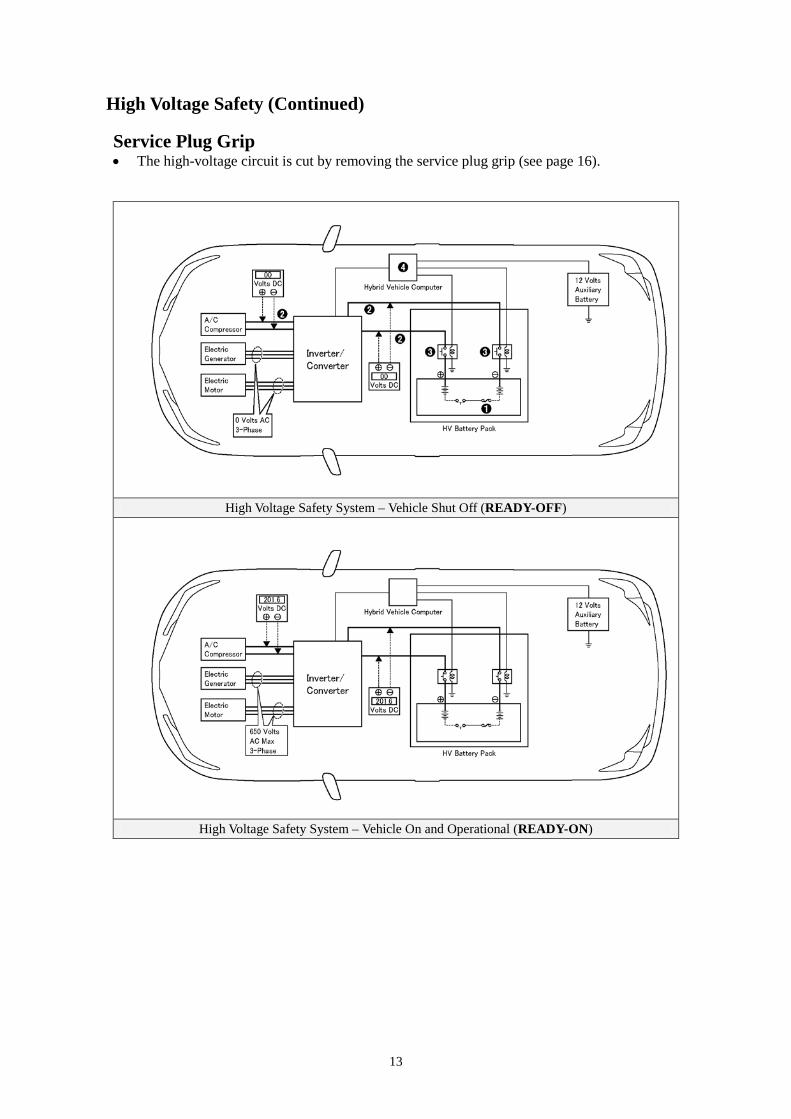
High Voltage Safety (Continued) Service Plug Grip • The high-voltage circuit is cut by removing the service plug grip (see page 16).
High Voltage Safety System – Vehicle Shut Off (READY-OFF)
High Voltage Safety System – Vehicle On and Operational (READY-ON)
14
Precaution to be observed when dismantling the vehicle
WARNING:
・ The high voltage system may remain powered for up to 10 minutes after the vehicle is shut off or disabled. To prevent serious injury or death from severe burns or electric shock, avoid touching, cutting, or breaching any orange high voltage power cable or high voltage component.
Necessary Items • Protective clothing such as insulated gloves (electrically insulated), rubber gloves, safety goggles,
and safety shoes. • Insulating tape such as electrical tape that has a suitable electrical insulation rating. • Before wearing insulated gloves, make sure that they are not cracked, ruptured, torn, or damaged in
any way. Do not wear wet insulated gloves. • An electrical tester that is capable of measuring DC 750 Volts or more.
15
Spills The AURIS Hybrid contains the same common automotive fluids used in other non-hybrid Toyota vehicles, with the exception of the NiMH electrolyte used in the HV battery pack. The NiMH battery electrolyte is a caustic alkaline (pH 13.5) that is damaging to human tissues. The electrolyte, however, is absorbed in the cell plates and will not normally spill or leak out even if a battery module is cracked. A catastrophic crash that would breach both the metal battery pack case and a metal battery module would be a rare occurrence.
A caustic alkaline is at the opposite end of the pH scale from a strong acid. A safe (neutral) substance is approximately in the middle of this scale. Adding a weak acidic mixture, such as a dilute boric acid solution or vinegar, to the caustic alkaline electrolyte will cause the electrolyte to be neutralized. This is similar but opposite to the use of baking soda to neutralize a lead-acid battery electrolyte spill.
A Toyota Product Safety Data Sheets (PSDS) is attached to this document.
• Handle NiMH electrolyte spills using the following Personal Protective Equipment (PPE):
• Splash shield or safety goggles. Fold down helmet shields are not acceptable for acid or electrolyte spills.
• Rubber, latex or nitrile gloves. • Apron suitable for alkaline. • Rubber boots.
• Neutralize NiMH electrolyte.
• Use a boric acid solution or vinegar. • Boric acid solution - 800 grams boric acid to 20 liters water or 5.5 ounces boric acid to 1
gallon of water.
16
Dismantling a vehicle
The following 2 pages contain general instructions for use when working on an AURIS Hybrid. Read these instructions before proceeding to the HV battery removal instructions on page 19.
WARNING:
・ The high voltage system may remain powered for up to 10 minutes after the vehicle is shut off or disabled. To prevent serious injury or death from severe burns or electric shock, avoid touching, cutting, or breaching any orange high voltage power cable or any high voltage component.
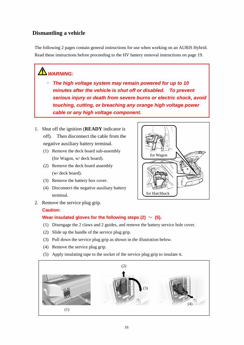
1. Shut off the ignition (READY indicator is off). Then disconnect the cable from the negative auxiliary battery terminal. (1) Remove the deck board sub-assembly
(for Wagon, w/ deck board). (2) Remove the deck board assembly
(w/ deck board). (3) Remove the battery box cover. (4) Disconnect the negative auxiliary battery
terminal.
2. Remove the service plug grip. Caution: Wear insulated gloves for the following steps (2) ~ (5). (1) Disengage the 2 claws and 2 guides, and remove the battery service hole cover. (2) Slide up the handle of the service plug grip. (3) Pull down the service plug grip as shown in the illustration below. (4) Remove the service plug grip. (5) Apply insulating tape to the socket of the service plug grip to insulate it.
(1)
(2)
(3)
(4)
for Wagon
for Hatchback
17
3. Carry the removed service plug grip in your pocket to prevent other staff from accidentally reinstalling it while you are dismantling the vehicle.
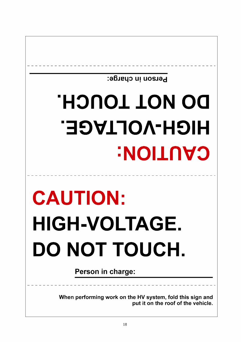
4. Make other staff aware that a high-voltage system is being dismantled by using the following sign: CAUTION: HIGH-VOLTAGE. DO NOT TOUCH (see page 18).
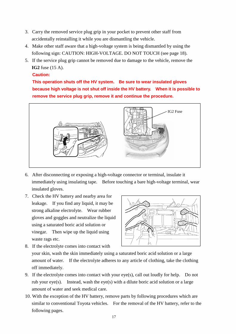
5. If the service plug grip cannot be removed due to damage to the vehicle, remove the IG2 fuse (15 A). Caution: This operation shuts off the HV system. Be sure to wear insulated gloves because high voltage is not shut off inside the HV battery. When it is possible to remove the service plug grip, remove it and continue the procedure.
6. After disconnecting or exposing a high-voltage connector or terminal, insulate it immediately using insulating tape. Before touching a bare high-voltage terminal, wear insulated gloves.
7. Check the HV battery and nearby area for leakage. If you find any liquid, it may be strong alkaline electrolyte. Wear rubber gloves and goggles and neutralize the liquid using a saturated boric acid solution or vinegar. Then wipe up the liquid using waste rags etc.
8. If the electrolyte comes into contact with your skin, wash the skin immediately using a saturated boric acid solution or a large amount of water. If the electrolyte adheres to any article of clothing, take the clothing off immediately.
9. If the electrolyte comes into contact with your eye(s), call out loudly for help. Do not rub your eye(s). Instead, wash the eye(s) with a dilute boric acid solution or a large amount of water and seek medical care.
10. With the exception of the HV battery, remove parts by following procedures which are similar to conventional Toyota vehicles. For the removal of the HV battery, refer to the following pages.
IG2 Fuse
18
19
Removal of HV battery
WARNING:
・ Be sure to wear insulated gloves when handling high-voltage parts.
・ Even if the vehicle is shut off and the relays are off, be sure to remove the service plug grip before performing any further work.
・ Power remains in the high voltage electrical system for 10 minutes even after the HV battery pack is shut off because the circuit has a condenser that stores power.
・ Make sure that the tester reading is 0 V before touching any high-voltage terminals which are not insulated.
・ The SRS may remain powered for up to 90 seconds after the vehicle is shut off or disabled. To prevent serious injury or death from unintentional SRS deployment, avoid cutting the SRS components.
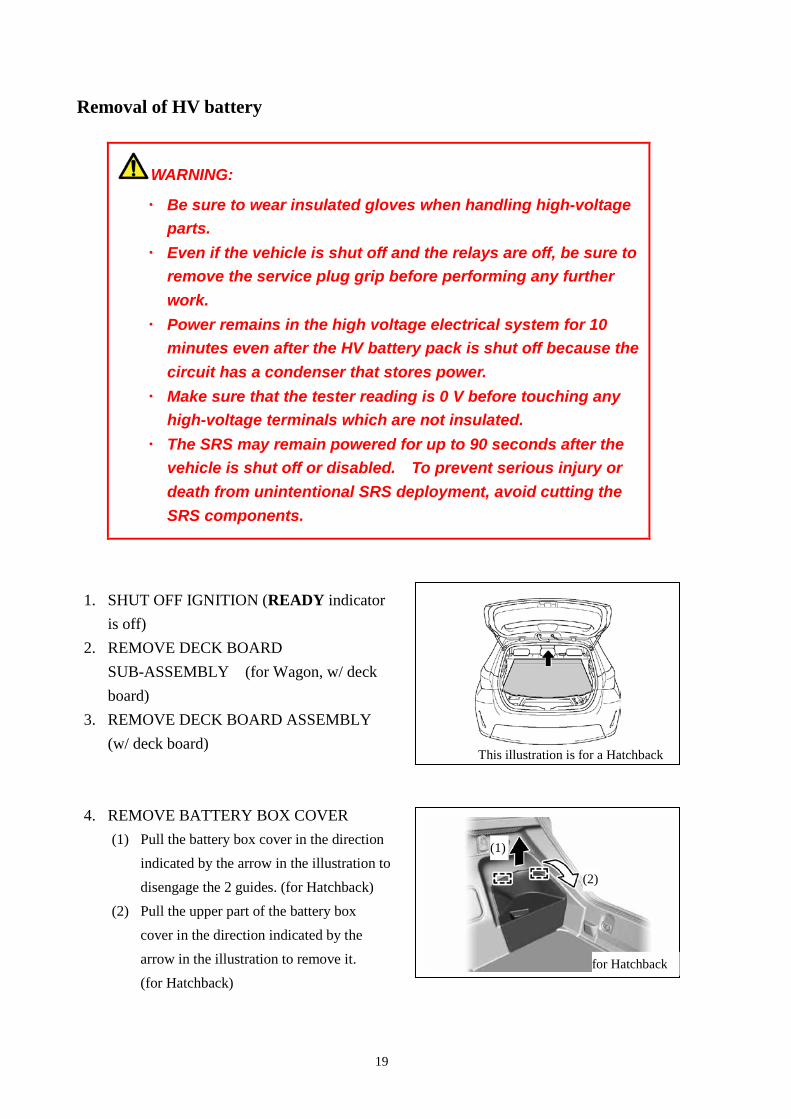
1. SHUT OFF IGNITION (READY indicator is off)
2. REMOVE DECK BOARD SUB-ASSEMBLY (for Wagon, w/ deck board)
3. REMOVE DECK BOARD ASSEMBLY (w/ deck board)
4. REMOVE BATTERY BOX COVER
(1) Pull the battery box cover in the direction indicated by the arrow in the illustration to disengage the 2 guides. (for Hatchback)
(2) Pull the upper part of the battery box cover in the direction indicated by the arrow in the illustration to remove it. (for Hatchback)
(1)
(2)
for Hatchback
This illustration is for a Hatchback
20
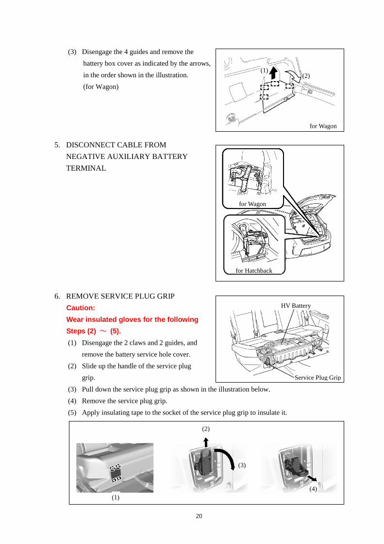
(3) Disengage the 4 guides and remove the battery box cover as indicated by the arrows, in the order shown in the illustration. (for Wagon)
5. DISCONNECT CABLE FROM NEGATIVE AUXILIARY BATTERY TERMINAL
6. REMOVE SERVICE PLUG GRIP Caution: Wear insulated gloves for the following Steps (2) ~ (5). (1) Disengage the 2 claws and 2 guides, and
remove the battery service hole cover. (2) Slide up the handle of the service plug
grip. (3) Pull down the service plug grip as shown in the illustration below. (4) Remove the service plug grip. (5) Apply insulating tape to the socket of the service plug grip to insulate it.
HV Battery
(1)
(2)
(3)
(4)
for Wagon
for Hatchback
for Wagon
(1) (2)
Service Plug Grip
21
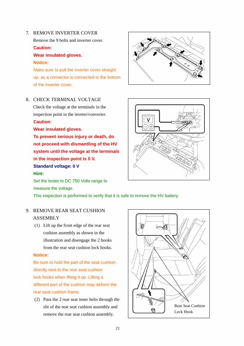
7. REMOVE INVERTER COVER Remove the 9 bolts and inverter cover.
Caution: Wear insulated gloves. Notice: Make sure to pull the inverter cover straight
up, as a connector is connected to the bottom
of the inverter cover.
8. CHECK TERMINAL VOLTAGE
Check the voltage at the terminals in the inspection point in the inveter/converter.
Caution: Wear insulated gloves. To prevent serious injury or death, do not proceed with dismantling of the HV system until the voltage at the terminals in the inspection point is 0 V. Standard voltage: 0 V Hint: Set the tester to DC 750 Volts range to
measure the voltage.
This inspection is performed to verify that it is safe to remove the HV battery.
9. REMOVE REAR SEAT CUSHION
ASSEMBLY (1) Lift up the front edge of the rear seat
cushion assembly as shown in the illustration and disengage the 2 hooks from the rear seat cushion lock hooks.
Notice: Be sure to hold the part of the seat cushion
directly next to the rear seat cushion
lock hooks when lifting it up. Lifting a
different part of the cushion may deform the
rear seat cushion frame.
(2) Pass the 2 rear seat inner belts through the slit of the rear seat cushion assembly and remove the rear seat cushion assembly.
Rear Seat Cushion Lock Hook
22
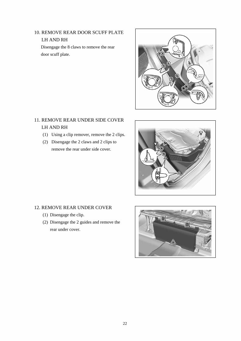
10. REMOVE REAR DOOR SCUFF PLATE LH AND RH Disengage the 8 claws to remove the rear door scuff plate.
11. REMOVE REAR UNDER SIDE COVER LH AND RH (1) Using a clip remover, remove the 2 clips. (2) Disengage the 2 claws and 2 clips to
remove the rear under side cover.
12. REMOVE REAR UNDER COVER (1) Disengage the clip. (2) Disengage the 2 guides and remove the
rear under cover.
23
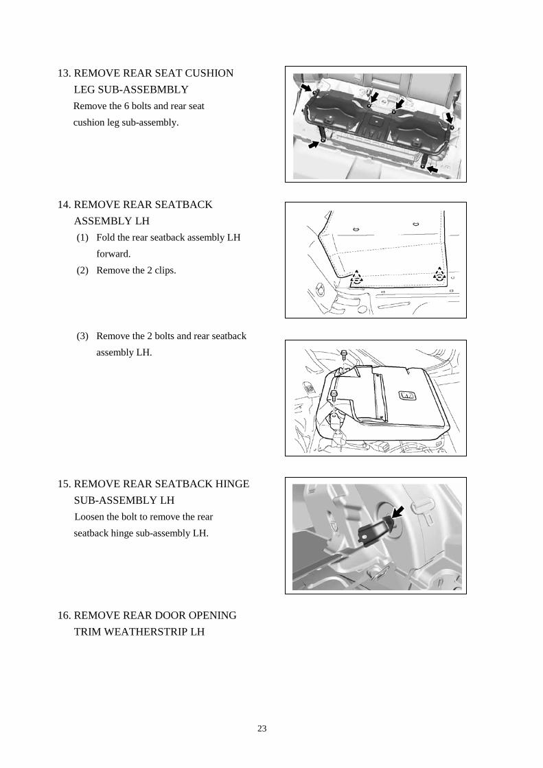
13. REMOVE REAR SEAT CUSHION LEG SUB-ASSEBMBLY Remove the 6 bolts and rear seat cushion leg sub-assembly.
14. REMOVE REAR SEATBACK
ASSEMBLY LH (1) Fold the rear seatback assembly LH
forward. (2) Remove the 2 clips.
(3) Remove the 2 bolts and rear seatback
assembly LH.
15. REMOVE REAR SEATBACK HINGE SUB-ASSEMBLY LH Loosen the bolt to remove the rear seatback hinge sub-assembly LH.
16. REMOVE REAR DOOR OPENING TRIM WEATHERSTRIP LH
24
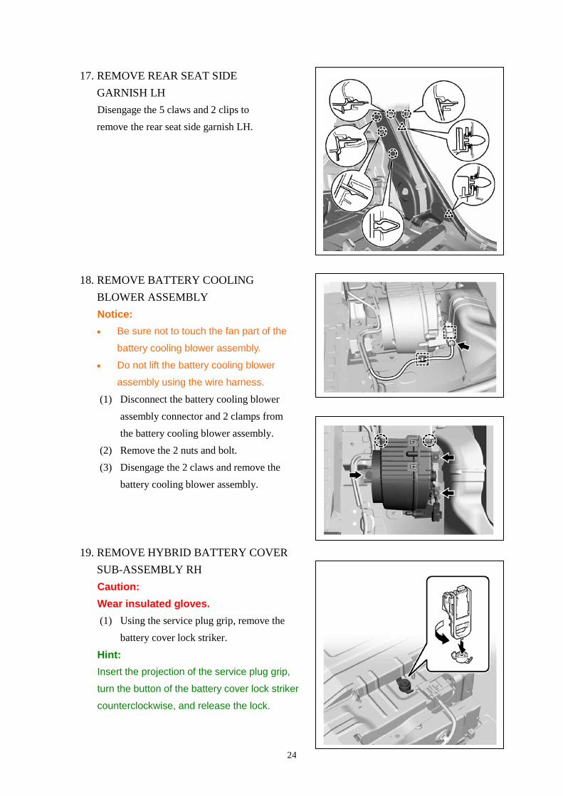
17. REMOVE REAR SEAT SIDE GARNISH LH Disengage the 5 claws and 2 clips to remove the rear seat side garnish LH.
18. REMOVE BATTERY COOLING
BLOWER ASSEMBLY Notice: • Be sure not to touch the fan part of the
battery cooling blower assembly.
• Do not lift the battery cooling blower
assembly using the wire harness.
(1) Disconnect the battery cooling blower assembly connector and 2 clamps from the battery cooling blower assembly.
(2) Remove the 2 nuts and bolt. (3) Disengage the 2 claws and remove the
battery cooling blower assembly.
19. REMOVE HYBRID BATTERY COVER SUB-ASSEMBLY RH Caution: Wear insulated gloves. (1) Using the service plug grip, remove the
battery cover lock striker.
Hint: Insert the projection of the service plug grip,
turn the button of the battery cover lock striker
counterclockwise, and release the lock.
25
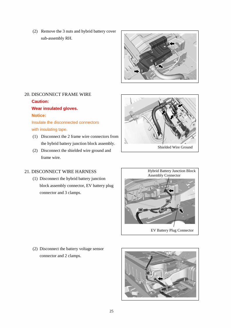
(2) Remove the 3 nuts and hybrid battery cover sub-assembly RH.
20. DISCONNECT FRAME WIRE Caution: Wear insulated gloves. Notice: Insulate the disconnected connectors
with insulating tape.
(1) Disconnect the 2 frame wire connectors from the hybrid battery junction block assembly.
(2) Disconnect the shielded wire ground and frame wire.
21. DISCONNECT WIRE HARNESS (1) Disconnect the hybrid battery junction
block assembly connector, EV battery plug connector and 3 clamps.
(2) Disconnect the battery voltage sensor connector and 2 clamps.
Shielded Wire Ground
Hybrid Battery Junction Block Assembly Connector
EV Battery Plug Connector
26
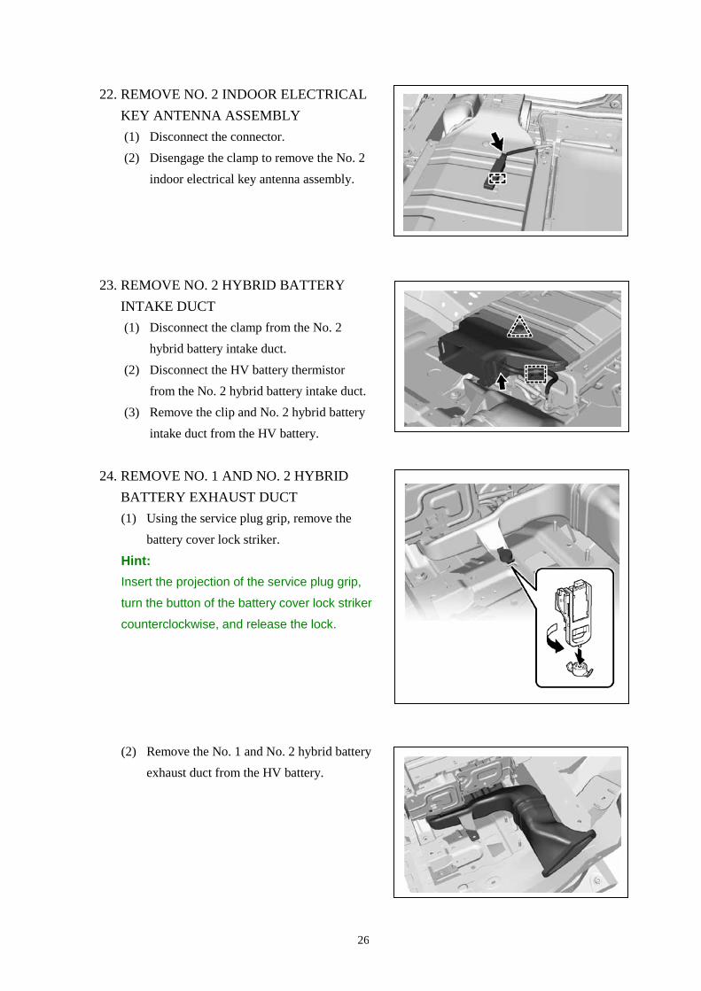
22. REMOVE NO. 2 INDOOR ELECTRICAL KEY ANTENNA ASSEMBLY (1) Disconnect the connector. (2) Disengage the clamp to remove the No. 2
indoor electrical key antenna assembly.
23. REMOVE NO. 2 HYBRID BATTERY
INTAKE DUCT (1) Disconnect the clamp from the No. 2
hybrid battery intake duct. (2) Disconnect the HV battery thermistor
from the No. 2 hybrid battery intake duct. (3) Remove the clip and No. 2 hybrid battery
intake duct from the HV battery.
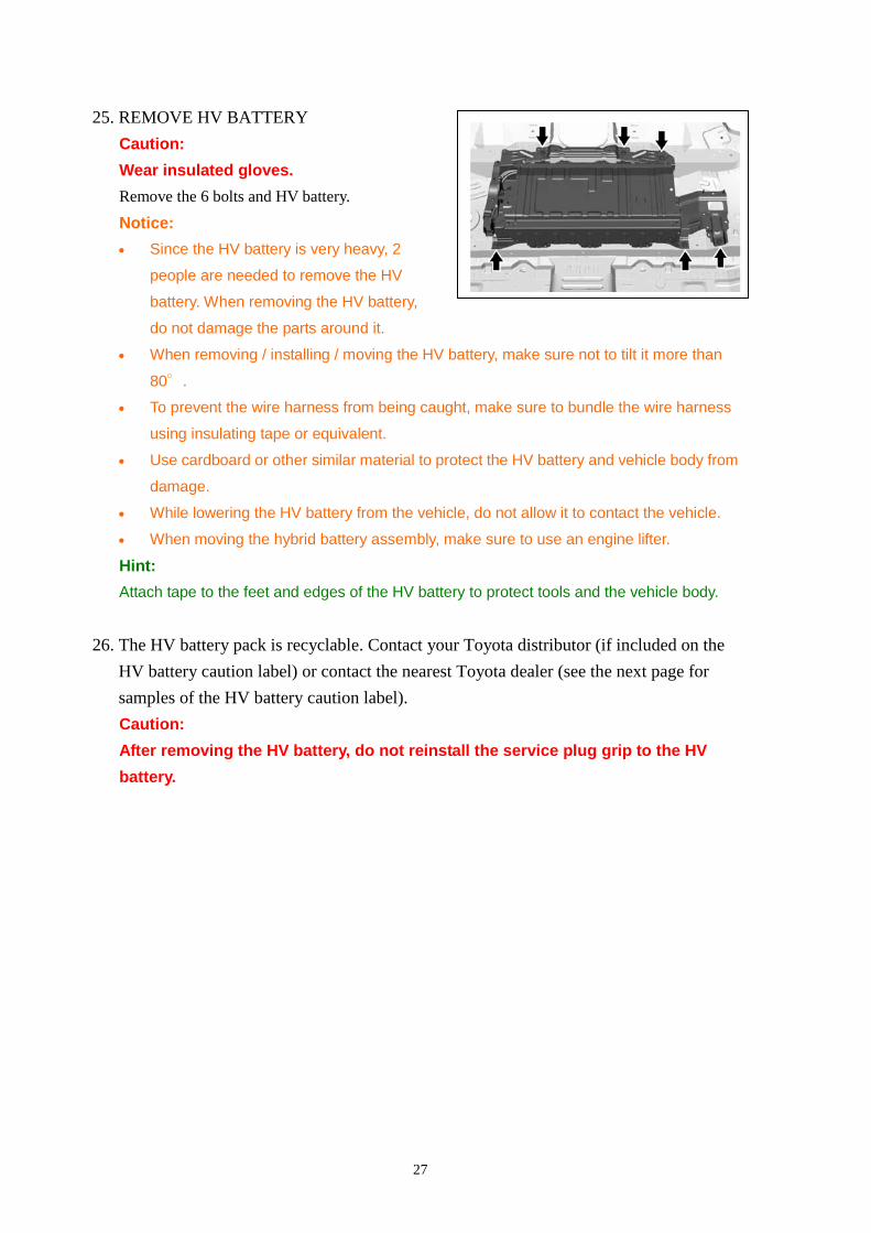
24. REMOVE NO. 1 AND NO. 2 HYBRID BATTERY EXHAUST DUCT (1) Using the service plug grip, remove the
battery cover lock striker.
Hint: Insert the projection of the service plug grip,
turn the button of the battery cover lock striker
counterclockwise, and release the lock.
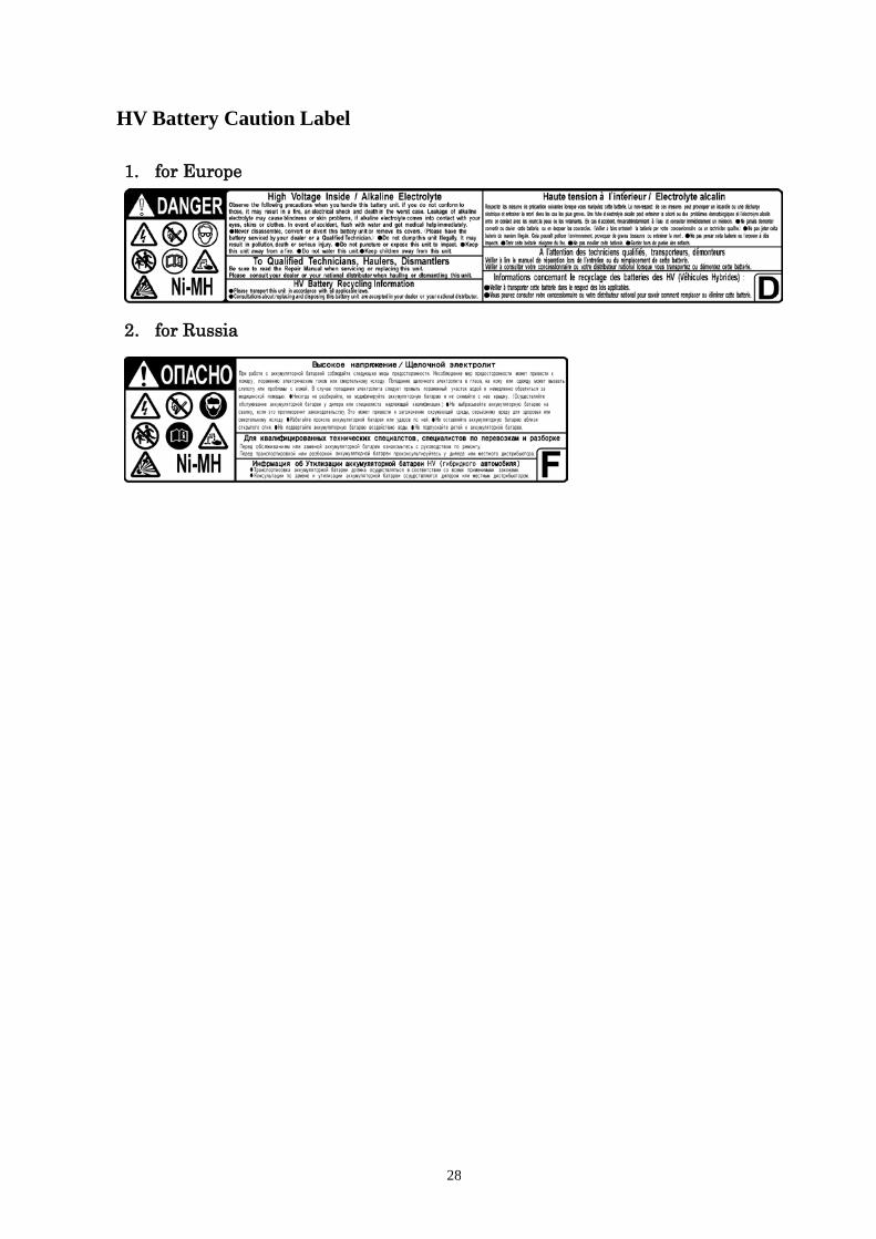
(2) Remove the No. 1 and No. 2 hybrid battery exhaust duct from the HV battery.
27
25. REMOVE HV BATTERY Caution: Wear insulated gloves. Remove the 6 bolts and HV battery.
Notice: • Since the HV battery is very heavy, 2
people are needed to remove the HV
battery. When removing the HV battery,
do not damage the parts around it.
• When removing / installing / moving the HV battery, make sure not to tilt it more than
80°.
• To prevent the wire harness from being caught, make sure to bundle the wire harness
using insulating tape or equivalent.
• Use cardboard or other similar material to protect the HV battery and vehicle body from
damage.
• While lowering the HV battery from the vehicle, do not allow it to contact the vehicle.
• When moving the hybrid battery assembly, make sure to use an engine lifter.
Hint: Attach tape to the feet and edges of the HV battery to protect tools and the vehicle body.
26. The HV battery pack is recyclable. Contact your Toyota distributor (if included on the HV battery caution label) or contact the nearest Toyota dealer (see the next page for samples of the HV battery caution label). Caution: After removing the HV battery, do not reinstall the service plug grip to the HV battery.
28
HV Battery Caution Label 1. for Europe
2. for Russia