Embed Size (px)
Citation preview
Gasoline-Electric
Hybrid Synergy Drive
Revised
AHV4# Series
i
ii
Foreword
This guide was developed to educate and assist dismantlers in the safe handling of Toyota Camry
gasoline-electric hybrid vehicles. Camry Hybrid dismantling procedures are similar to other
non-hybrid Toyota vehicles with the exception of the high voltage electrical system. It is important to
recognize and understand the high voltage electrical system features and specifications of the Toyota
Camry Hybrid, as they may not be familiar to dismantlers.
High voltage electricity powers the electric motor, generator, A/C compressor, and
inverter/converter. All other automotive electrical devices such as the headlights, power steering,
horn, radio, and gauges are powered from a separate 12 Volts battery. Numerous safeguards have
been designed into the CAMRY to help ensure the high voltage, approximately 245 Volts, Nickel
Metal Hydride (NiMH) Hybrid Vehicle (HV) battery pack is kept safe and secure in an accident.
Additional topics contained in the guide include:
• Toyota CAMRY identification.
• Major hybrid component locations and descriptions.
By following the information in this guide, dismantlers will be able to handle the CAMRY
hybrid-electric vehicle as safely as the dismantling of a conventional gasoline engine automobile.
© 2009 Toyota Motor Corporation All rights reserved. This book may not be reproduced or copied, in whole or in part, without the written permission of Toyota Motor Corporation
iii
Table of Contents
About the CAMRY......................................................................................................................... 1
CAMRY Identification ................................................................................................................... 2 Exterior .........................................................................................................................................................3
CAMRY Identification (Continued)................................................................................................ 5 Interior...........................................................................................................................................................5 Engine Compartment ....................................................................................................................................6
Hybrid Component Locations & Descriptions ................................................................................ 7 Specifications..............................................................................................................................................88
Hybrid Synergy Drive Operation ................................................................................................... 9 Vehicle Operation..........................................................................................................................................9
Hybrid Vehicle (HV) Battery Pack and Auxiliary Battery............................................................. 10 Components to Which High Voltage is Applied ...........................................................................................10 HV Battery Pack Recycling ......................................................................................................................... 11
High Voltage Safety ...................................................................................................................... 12 Service Plug................................................................................................................................................13
Precaution to be observed when dismantling the vehicle ............................................................... 14 Necessary items .........................................................................................................................................14
Spillage ........................................................................................................................................ 15
Dismantling a vehicle ................................................................................................................... 16
Removal of HV battery................................................................................................................. 19 HV battery removal .....................................................................................................................................19 HV Battery Caution Label ...........................................................................................................................31

About the CAMRY
The CAMRY hybrid sedan joins the PRIUS and HIGHLANDER hybrid as a hybrid model for Toyota. Hybrid Synergy Drive means that the vehicle contains a gasoline engine and an electric motor for power. The two hybrid power sources are stored on board the vehicle: 1. Gasoline stored in the fuel tank for the gasoline engine. 2. Electricity stored in a high voltage Hybrid Vehicle (HV) battery pack for the electric
motor. The result of combining these two power sources is improved fuel economy and reduced emissions. The gasoline engine also powers an electric generator to recharge the battery pack; unlike a pure all electric vehicle, the CAMRY hybrid never needs to be recharged from an external electric power source.
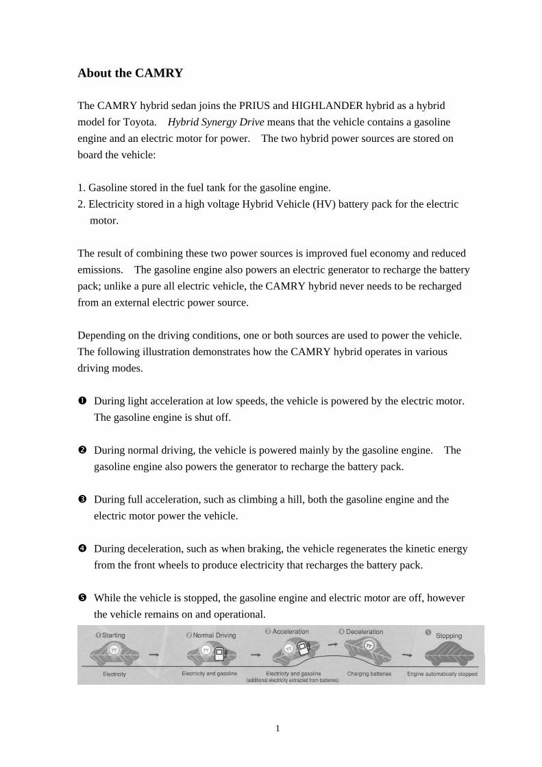
Depending on the driving conditions, one or both sources are used to power the vehicle. The following illustration demonstrates how the CAMRY hybrid operates in various driving modes.
During light acceleration at low speeds, the vehicle is powered by the electric motor. The gasoline engine is shut off.
During normal driving, the vehicle is powered mainly by the gasoline engine. The
gasoline engine also powers the generator to recharge the battery pack.
During full acceleration, such as climbing a hill, both the gasoline engine and the electric motor power the vehicle.
During deceleration, such as when braking, the vehicle regenerates the kinetic energy
from the front wheels to produce electricity that recharges the battery pack.
While the vehicle is stopped, the gasoline engine and electric motor are off, however the vehicle remains on and operational.
1

CAMRY Identification
In appearance, the CAMRY hybrid is nearly identical to the conventional, non-hybrid Toyota CAMRY.
The CAMRY hybrid is a 4-door sedan. Exterior, interior, and engine compartment illustrations are
provided to assist in identification.
The alphanumeric 17 character Vehicle Identification Number (VIN) is provided in the front windshield cowl or right side floor and left side door pillar.
Example VIN:
JTNBB46S######### (2007 to 2009 models for U.S.A. and Canada)
4T1BB46S######### (2007 to 2009 models for U.S.A. and Canada)
JTNBB3EK######### (2010 model for U.S.A., Canada and South Korea)
4T1BB3EK######### (2010 model for U.S.A. and Canada)
LVGBB40K######### (for China)
6T153FK4######### (for Australia and New Zealand)
MR053FK4######### (for Thailand)
A CAMRY hybrid is identified by the first 6 alphanumeric characters JTNBB4, 4T1BB4, JTNBB3,
4T1BB3, LVGBB4, 6T153F and MR053FK
Driver Side Windshield and Driver Side B Pillar
For U.S.A., Canada and South Korea:
Front Passenger Door Pillar and Under Front Right Side Seat
Others:
2
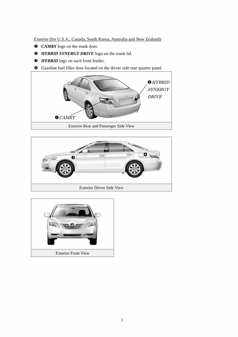
Exterior (for U.S.A., Canada, South Korea, Australia and New Zealand)
CAMRY logo on the trunk door. HYBRID SYNERGY DRIVE logo on the trunk lid. HYBRID logo on each front fender. Gasoline fuel filler door located on the driver side rear quarter panel.
Exterior Rear and Passenger Side View
HYBRID SYNERGY DRIVE
CAMRY
Exterior Driver Side View
Exterior Front View
3
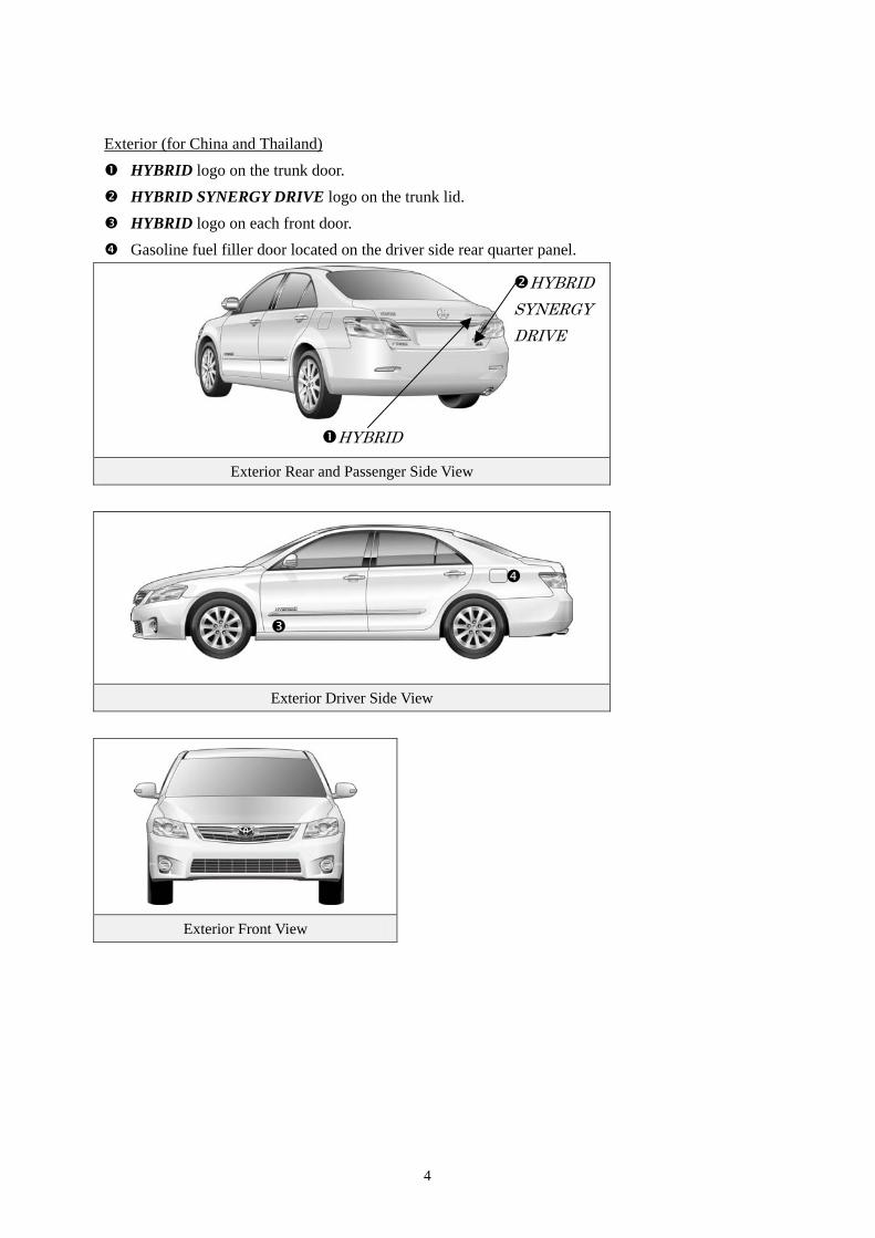
Exterior (for China and Thailand)
HYBRID logo on the trunk door. HYBRID SYNERGY DRIVE logo on the trunk lid. HYBRID logo on each front door. Gasoline fuel filler door located on the driver side rear quarter panel.
Exterior Rear and Passenger Side View
HYBRID SYNERGY DRIVE
HYBRID
Exterior Driver Side View
Exterior Front View
4
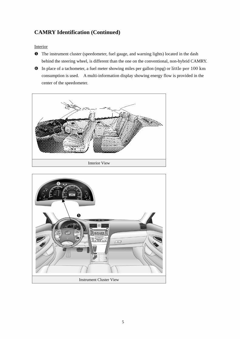
CAMRY Identification (Continued) Interior The instrument cluster (speedometer, fuel gauge, and warning lights) located in the dash
behind the steering wheel, is different than the one on the conventional, non-hybrid CAMRY.
In place of a tachometer, a fuel meter showing miles per gallon (mpg) or little per 100 km consumption is used. A multi-information display showing energy flow is provided in the center of the speedometer.
Interior View
Instrument Cluster View
5
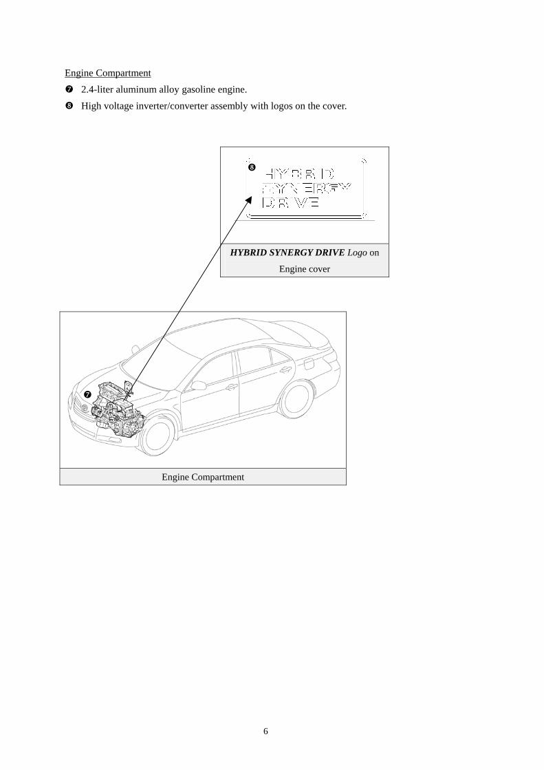
Engine Compartment 2.4-liter aluminum alloy gasoline engine. High voltage inverter/converter assembly with logos on the cover.
HYBRID SYNERGY DRIVE Logo on
Engine cover
Engine Compartment
6
7
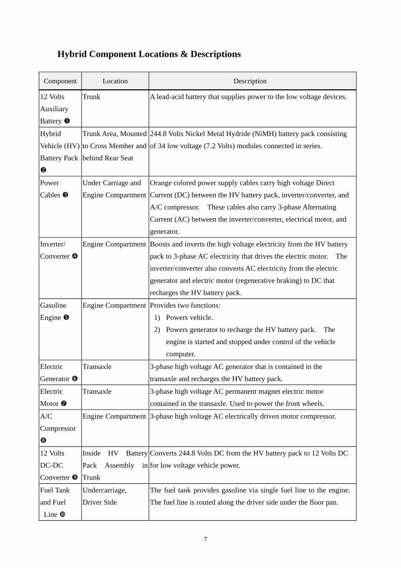
Hybrid Component Locations & Descriptions
Component Location Description
12 Volts Auxiliary Battery
Trunk A lead-acid battery that supplies power to the low voltage devices.
Hybrid Vehicle (HV) Battery Pack
Trunk Area, Mounted to Cross Member and behind Rear Seat
244.8 Volts Nickel Metal Hydride (NiMH) battery pack consisting of 34 low voltage (7.2 Volts) modules connected in series.
Power Cables
Under Carriage and Engine Compartment
Orange colored power supply cables carry high voltage Direct Current (DC) between the HV battery pack, inverter/converter, and A/C compressor. These cables also carry 3-phase Alternating Current (AC) between the inverter/converter, electrical motor, and generator.
Inverter/ Converter
Engine Compartment Boosts and inverts the high voltage electricity from the HV battery pack to 3-phase AC electricity that drives the electric motor. The inverter/converter also converts AC electricity from the electric generator and electric motor (regenerative braking) to DC that recharges the HV battery pack.
Gasoline Engine
Engine Compartment Provides two functions: 1) Powers vehicle. 2) Powers generator to recharge the HV battery pack. The
engine is started and stopped under control of the vehicle computer.
Electric Generator
Transaxle 3-phase high voltage AC generator that is contained in the transaxle and recharges the HV battery pack.
Electric Motor
Transaxle 3-phase high voltage AC permanent magnet electric motor contained in the transaxle. Used to power the front wheels.
A/C Compressor
Engine Compartment 3-phase high voltage AC electrically driven motor compressor.
12 Volts DC-DC Converter
Inside HV Battery Pack Assembly in Trunk
Converts 244.8 Volts DC from the HV battery pack to 12 Volts DC for low voltage vehicle power.
Fuel Tank and Fuel Line
Undercarriage, Driver Side
The fuel tank provides gasoline via single fuel line to the engine. The fuel line is routed along the driver side under the floor pan.
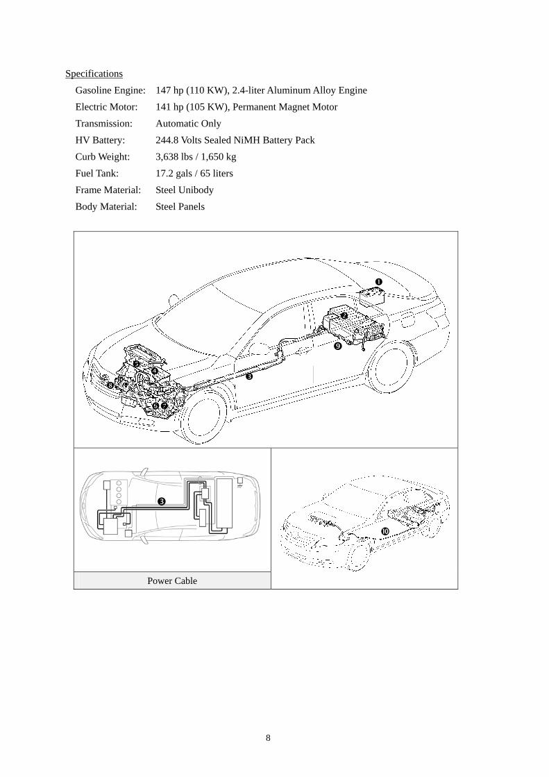
Specifications Gasoline Engine: 147 hp (110 KW), 2.4-liter Aluminum Alloy Engine Electric Motor: 141 hp (105 KW), Permanent Magnet Motor Transmission: Automatic Only HV Battery: 244.8 Volts Sealed NiMH Battery Pack Curb Weight: 3,638 lbs / 1,650 kg Fuel Tank: 17.2 gals / 65 liters Frame Material: Steel Unibody Body Material: Steel Panels
Power Cable
8
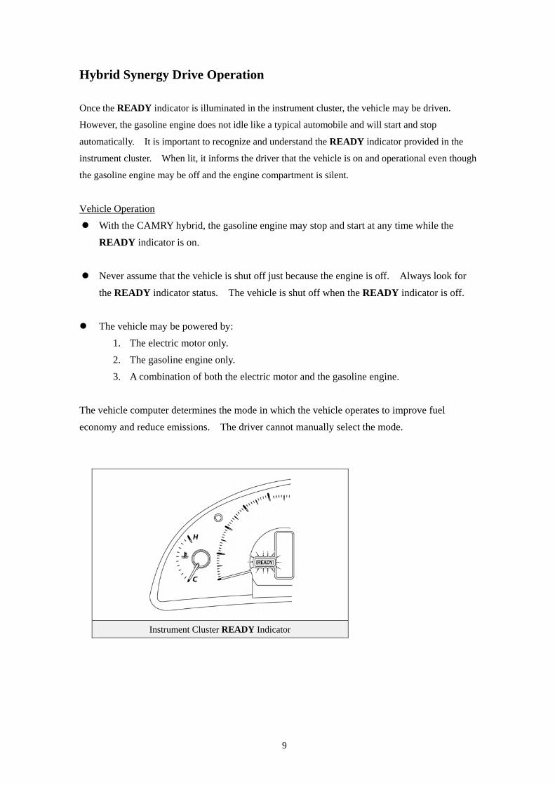
Hybrid Synergy Drive Operation
Once the READY indicator is illuminated in the instrument cluster, the vehicle may be driven.
However, the gasoline engine does not idle like a typical automobile and will start and stop
automatically. It is important to recognize and understand the READY indicator provided in the
instrument cluster. When lit, it informs the driver that the vehicle is on and operational even though
the gasoline engine may be off and the engine compartment is silent.
Vehicle Operation With the CAMRY hybrid, the gasoline engine may stop and start at any time while the
READY indicator is on. Never assume that the vehicle is shut off just because the engine is off. Always look for
the READY indicator status. The vehicle is shut off when the READY indicator is off. The vehicle may be powered by:
1. The electric motor only. 2. The gasoline engine only. 3. A combination of both the electric motor and the gasoline engine.
The vehicle computer determines the mode in which the vehicle operates to improve fuel economy and reduce emissions. The driver cannot manually select the mode.
Instrument Cluster READY Indicator
9
10
Hybrid Vehicle (HV) Battery Pack and Auxiliary Battery
The CAMRY hybrid contains a high voltage, Hybrid Vehicle (HV) battery pack that contains sealed
Nickel Metal Hydride (NiMH) battery modules.
HV Battery Pack • The HV battery pack is enclosed in a metal case and is securely mounted in the trunk area
behind the rear seat. The metal case is isolated from high voltage and concealed by fabric covers.
• The HV battery pack consists of 34 low voltage (7.2 Volts) NiMH battery modules connected in series to produce approximately 244.8 Volts. Each NiMH battery module is non-spillable and sealed in a plastic case.
• The electrolyte used in the NiMH battery module is an alkaline mixture of potassium and sodium hydroxide. The electrolyte is absorbed into the battery cell plates and forms a gel that will not normally leak, even in a collision.
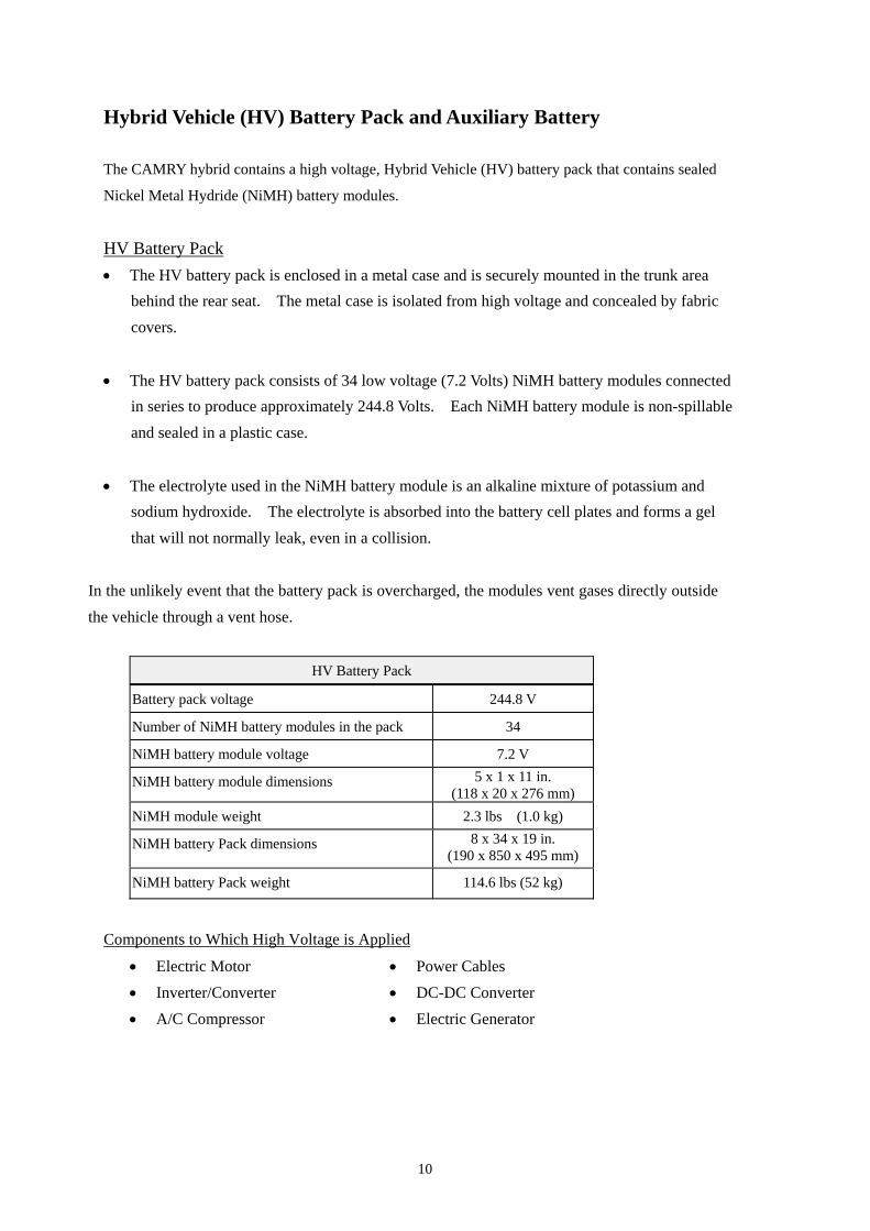
In the unlikely event that the battery pack is overcharged, the modules vent gases directly outside the vehicle through a vent hose.
HV Battery Pack
Battery pack voltage 244.8 V
Number of NiMH battery modules in the pack 34
NiMH battery module voltage 7.2 V
NiMH battery module dimensions 5 x 1 x 11 in. (118 x 20 x 276 mm)
NiMH module weight 2.3 lbs (1.0 kg)
NiMH battery Pack dimensions 8 x 34 x 19 in. (190 x 850 x 495 mm)
NiMH battery Pack weight 114.6 lbs (52 kg)
Components to Which High Voltage is Applied
• Electric Motor • Power Cables • Inverter/Converter • DC-DC Converter • A/C Compressor • Electric Generator
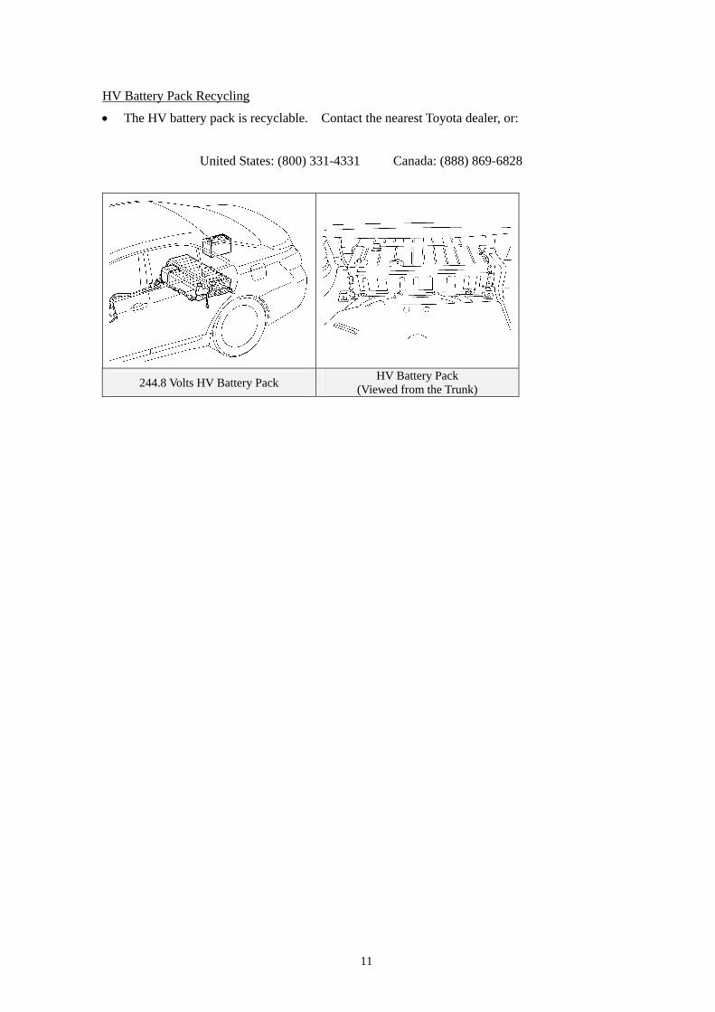
HV Battery Pack Recycling
• The HV battery pack is recyclable. Contact the nearest Toyota dealer, or:
United States: (800) 331-4331 Canada: (888) 869-6828
244.8 Volts HV Battery Pack HV Battery Pack (Viewed from the Trunk)
11
High Voltage Safety The HV battery pack powers the high voltage electrical system with DC electricity. Positive and negative orange colored high voltage power cables are routed from the battery pack, under the vehicle floor pan to the engine compartment, and connected to the inverter/converter. The inverter/converter contains a circuit that boosts the HV battery voltage from 244.8 up to 650 Volts DC. The inverter creates 3-phase AC to power the motor and generator located in the transaxle. Power cables are routed from the inverter to each high voltage motor (electric motor, electric generator, and A/C compressor). The following systems are intended to help occupants in the vehicle and emergency responders safe from high voltage electricity.
High Voltage Safety System • A high voltage fuse provides short circuit protection in the HV battery pack.
• Positive and negative high voltage power cables connected to the HV battery pack are controlled by 12 Volt normally open relays . When the vehicle is shut off, the relays stop electrical flow from leaving the HV battery pack.
WARNING:
The high voltage system may remain powered for up to 10 minutes after the vehicle is shut off or disabled. To prevent serious injury or death from severe burns or electric shock, avoid touching, cutting, or opening any orange high voltage power cable or high voltage component.
• Both positive and negative power cables are insulated from the metal chassis, so there is no possibility of electric shock when touching the metal chassis.
• A ground fault monitor continuously monitors for high voltage leakage to the metal chassis while the vehicle is running. If a malfunction is detected, the hybrid vehicle computer
will illuminate the master warning light in the instrument cluster and indicate “CHECK HYBRID SYSTEM” on the multi-information display.
• The HV battery pack relays will automatically open to stop the electrical flow in a collision sufficient to activate the SRS.
12
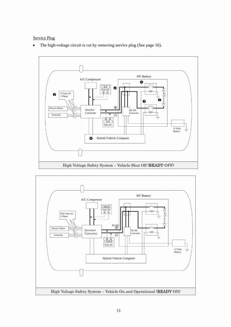
Service Plug
• The high-voltage circuit is cut by removing service plug (See page 16).
High Voltage Safety System – Vehicle Shut Off (READY-OFF)
HV Battery A/C Compressor
Volts DC
0 Volts AC 3-Phase
Electric Motor Inverter/
Converter DC/DC Converter
Generator
Volts DC 12 Volts Battery
Hybrid Vehicle Computer
High Voltage Safety System – Vehicle On and Operational (READY-ON)
12 Volts Battery
DC/DC Converter
HV Battery A/C Compressor
Volts DC
650 Volts AC 3-Phase
DC/DC Electric Motor
Inverter/ Converter Generator
Volts DC
Hybrid Vehicle Computer
13
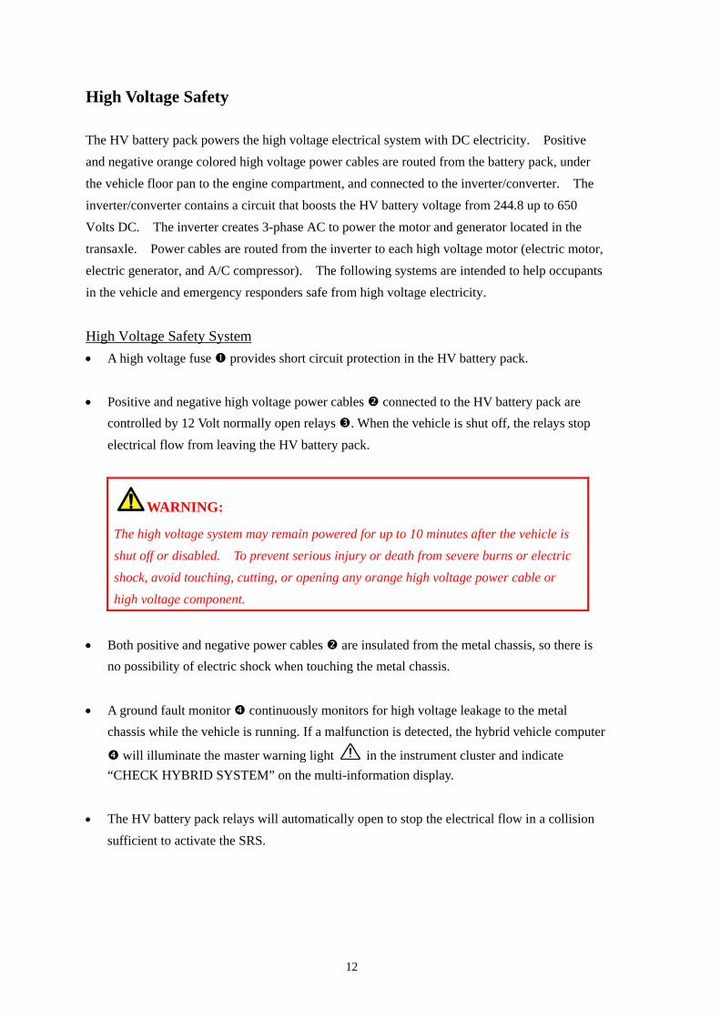
Precaution to be observed when dismantling the vehicle
WARNING:
・ The high voltage system may remain powered for up to 10 minutes after the vehicle is shut off or disabled. To prevent serious injury or death from severe burns or electric shock, avoid touching, cutting, or opening any orange high voltage power cable or high voltage component.
Necessary items
• Protective clothing (insulated gloves, rubber gloves, safety goggles, and safety shoes).
• Vinyl tape for insulation. • Before wearing insulated the vehicle gloves, make sure that they are not cracked,
ruptured, torn, or damaged in any other way. Do not wear wet insulated gloves.
14
15
Spillage The CAMRY contains the same common automotive fluids used in other non-hybrid Toyota vehicles, with the exception of NiMH electrolyte used in the HV battery pack. The NiMH battery electrolyte is a caustic alkaline (pH 13.5) that is damaging to human tissues. The electrolyte, however, is absorbed in the cell plates and will not normally spill or leak out even if a battery module is cracked. A catastrophic crash that would breach both the metal battery pack case and the plastic battery module would be a rare occurrence. Similar to the use of baking soda to neutralize a lead-acid battery electrolyte spill, a dilute boric acid solution or vinegar can be used to neutralize a NiMH battery electrolyte spill. In an emergency, Toyota Material Safety Data Sheets (MSDS) are available by contacting:
• Handle NiMH electrolyte Spills Using The following Personal Protective Equipment (PPE):
• Splash shield or safety goggles. Folding down helmet shields is not acceptable for alkaline spillage.
• Rubber, latex or Nitrile gloves. • Apron suitable for alkaline. • Rubber boots.
• Neutralize NiMH Electrolyte • Use a boric acid solution or vinegar.
• Boric acid solution - 800 grams boric acid to 20 liters water or 5.5 ounces boric acid to 1 gallon of water
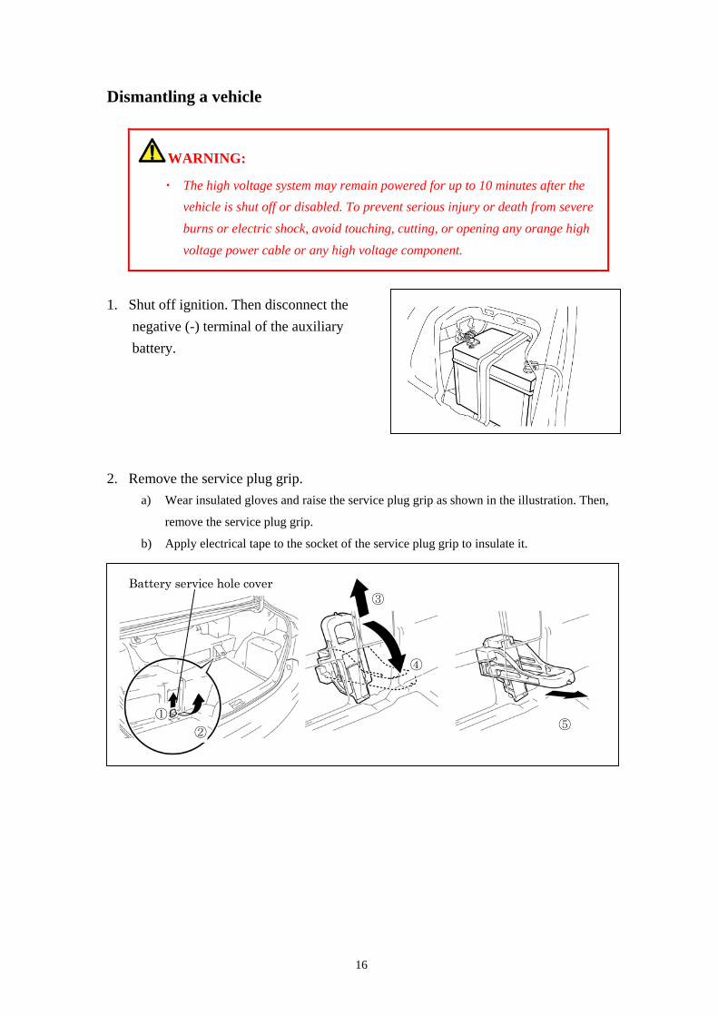
Dismantling a vehicle
WARNING:
・ The high voltage system may remain powered for up to 10 minutes after the vehicle is shut off or disabled. To prevent serious injury or death from severe burns or electric shock, avoid touching, cutting, or opening any orange high voltage power cable or any high voltage component.
1. Shut off ignition. Then disconnect the negative (-) terminal of the auxiliary battery.
2. Remove the service plug grip.
a) Wear insulated gloves and raise the service plug grip as shown in the illustration. Then,
remove the service plug grip.
b) Apply electrical tape to the socket of the service plug grip to insulate it.
Battery service hole cover
② ①
③
④
⑤
16
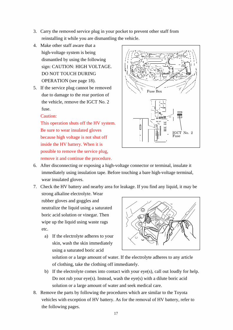
3. Carry the removed service plug in your pocket to prevent other staff from reinstalling it while you are dismantling the vehicle.
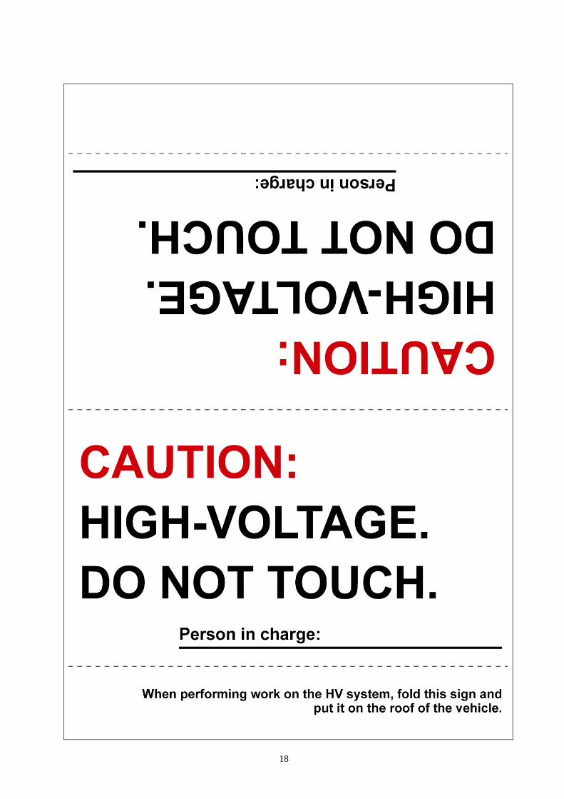
4. Make other staff aware that a high-voltage system is being dismantled by using the following sign: CAUTION: HIGH VOLTAGE. DO NOT TOUCH DURING OPERATION (see page 18).
IGCT No. 2Fuse
Fuse Box 5. If the service plug cannot be removed
due to damage to the rear portion of the vehicle, remove the IGCT No. 2 fuse. Caution: This operation shuts off the HV system. Be sure to wear insulated gloves because high voltage is not shut off inside the HV battery. When it is possible to remove the service plug, remove it and continue the procedure.
6. After disconnecting or exposing a high-voltage connector or terminal, insulate it immediately using insulation tape. Before touching a bare high-voltage terminal, wear insulated gloves.
7. Check the HV battery and nearby area for leakage. If you find any liquid, it may be strong alkaline electrolyte. Wear rubber gloves and goggles and neutralize the liquid using a saturated boric acid solution or vinegar. Then wipe up the liquid using waste rags etc.
a) If the electrolyte adheres to your skin, wash the skin immediately using a saturated boric acid solution or a large amount of water. If the electrolyte adheres to any article of clothing, take the clothing off immediately.
b) If the electrolyte comes into contact with your eye(s), call out loudly for help. Do not rub your eye(s). Instead, wash the eye(s) with a dilute boric acid solution or a large amount of water and seek medical care.
8. Remove the parts by following the procedures which are similar to the Toyota vehicles with exception of HV battery. As for the removal of HV battery, refer to the following pages.
17
18
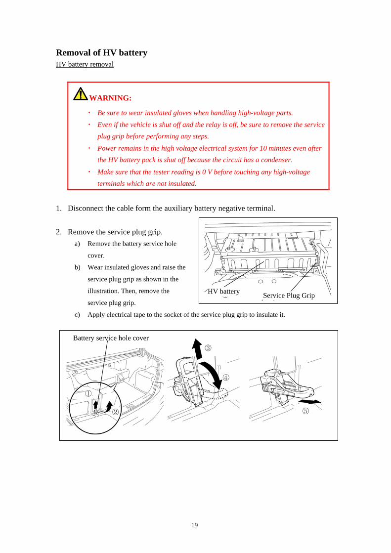
Removal of HV battery HV battery removal
WARNING:
・ Be sure to wear insulated gloves when handling high-voltage parts. ・ Even if the vehicle is shut off and the relay is off, be sure to remove the service
plug grip before performing any steps.
・ Power remains in the high voltage electrical system for 10 minutes even after the HV battery pack is shut off because the circuit has a condenser.
・ Make sure that the tester reading is 0 V before touching any high-voltage terminals which are not insulated.
1. Disconnect the cable form the auxiliary battery negative terminal. 2. Remove the service plug grip.
a) Remove the battery service hole
cover.
b) Wear insulated gloves and raise the
service plug grip as shown in the
illustration. Then, remove the
service plug grip.
c) Apply electrical tape to the socket of the service plug grip to insulate it.
HV battery
③
④
①
Battery service hole cover
Service Plug Grip
⑤ ②
19
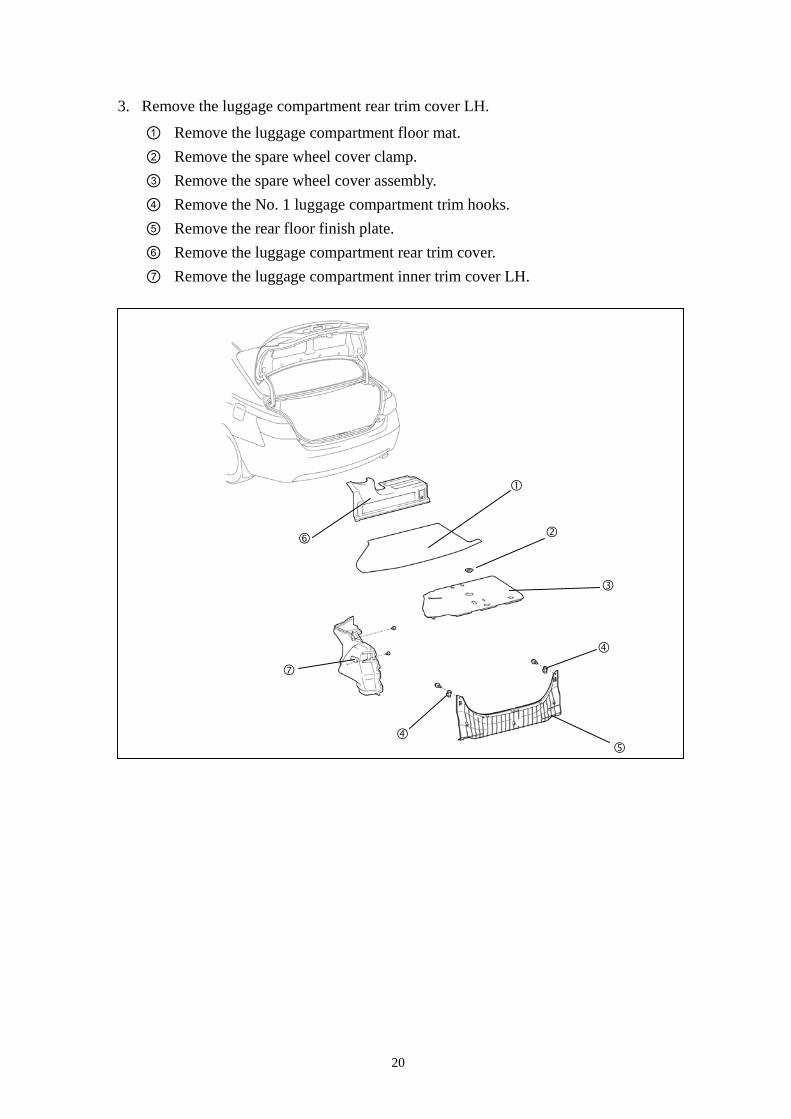
3. Remove the luggage compartment rear trim cover LH.
① Remove the luggage compartment floor mat. ② Remove the spare wheel cover clamp. ③ Remove the spare wheel cover assembly. ④ Remove the No. 1 luggage compartment trim hooks. ⑤ Remove the rear floor finish plate. ⑥ Remove the luggage compartment rear trim cover. ⑦ Remove the luggage compartment inner trim cover LH.
20
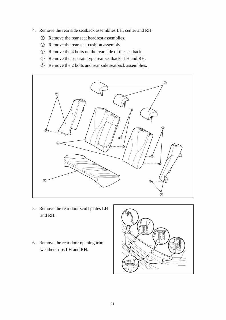
4. Remove the rear side seatback assemblies LH, center and RH.
① Remove the rear seat headrest assemblies. ② Remove the rear seat cushion assembly. ③ Remove the 4 bolts on the rear side of the seatback. ④ Remove the separate type rear seatbacks LH and RH. ⑤ Remove the 2 bolts and rear side seatback assemblies.
5. Remove the rear door scuff plates LH and RH.
6. Remove the rear door opening trim weatherstrips LH and RH.
21
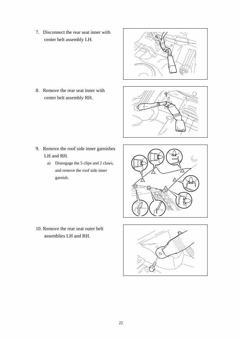
7. Disconnect the rear seat inner with center belt assembly LH.
8. Remove the rear seat inner with center belt assembly RH.
9. Remove the roof side inner garnishes LH and RH.
a) Disengage the 5 clips and 2 claws,
and remove the roof side inner
garnish.
10. Remove the rear seat outer belt assemblies LH and RH.
22
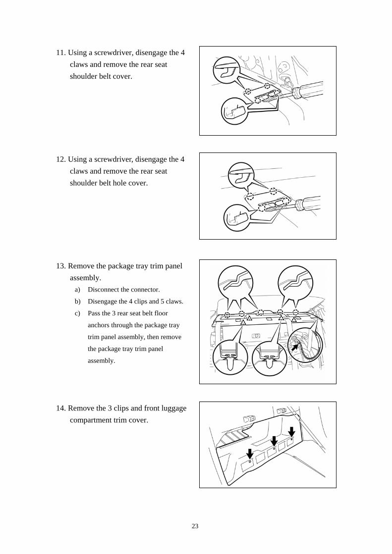
11. Using a screwdriver, disengage the 4 claws and remove the rear seat shoulder belt cover.
12. Using a screwdriver, disengage the 4 claws and remove the rear seat shoulder belt hole cover.
13. Remove the package tray trim panel assembly.
a) Disconnect the connector.
b) Disengage the 4 clips and 5 claws.
c) Pass the 3 rear seat belt floor
anchors through the package tray
trim panel assembly, then remove
the package tray trim panel
assembly.
14. Remove the 3 clips and front luggage compartment trim cover.
23
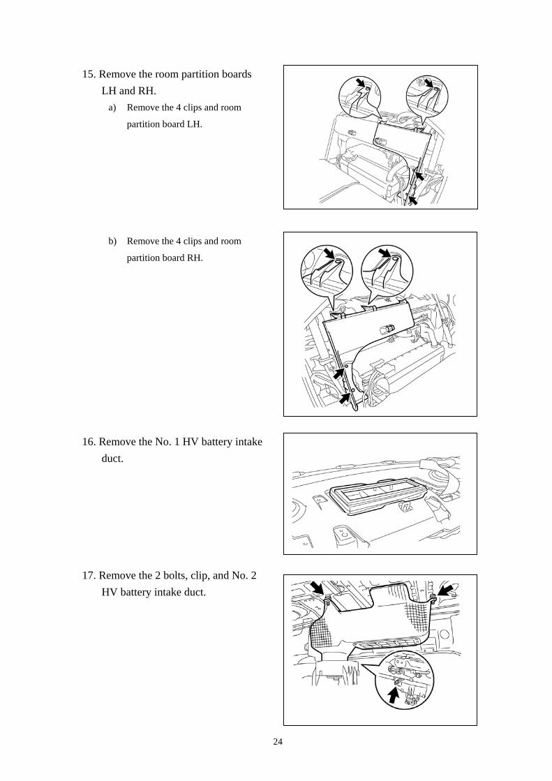
15. Remove the room partition boards LH and RH.
a) Remove the 4 clips and room
partition board LH.
b) Remove the 4 clips and room
partition board RH.
16. Remove the No. 1 HV battery intake duct.
17. Remove the 2 bolts, clip, and No. 2 HV battery intake duct.
24
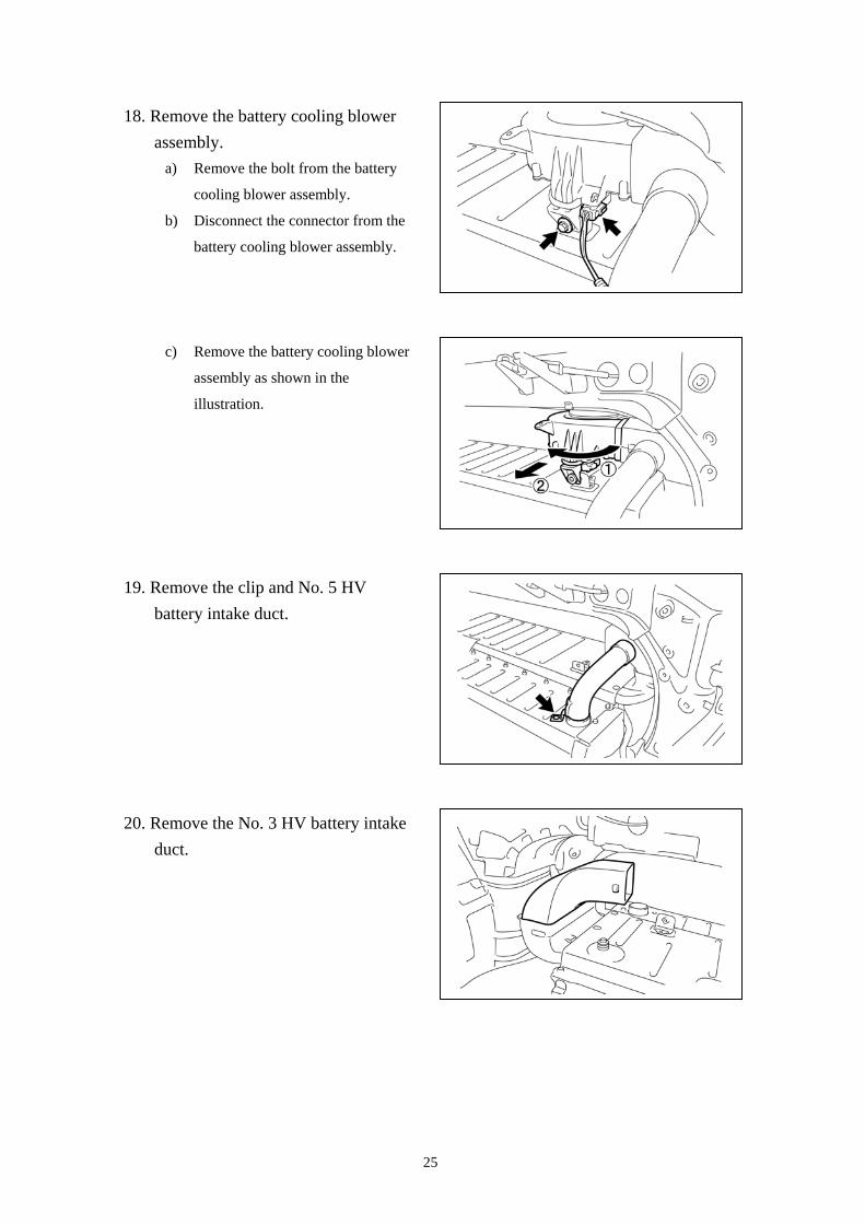
18. Remove the battery cooling blower assembly.
a) Remove the bolt from the battery
cooling blower assembly.
b) Disconnect the connector from the
battery cooling blower assembly.
c) Remove the battery cooling blower
assembly as shown in the
illustration.
19. Remove the clip and No. 5 HV battery intake duct.
20. Remove the No. 3 HV battery intake duct.
25
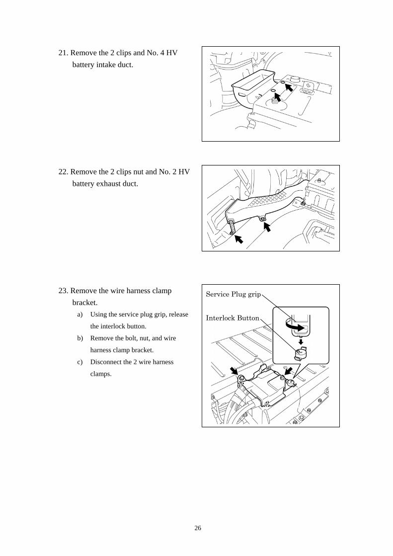
21. Remove the 2 clips and No. 4 HV battery intake duct.
22. Remove the 2 clips nut and No. 2 HV battery exhaust duct.
Interlock Button
Service Plug grip 23. Remove the wire harness clamp bracket.
a) Using the service plug grip, release
the interlock button.
b) Remove the bolt, nut, and wire
harness clamp bracket.
c) Disconnect the 2 wire harness
clamps.
26
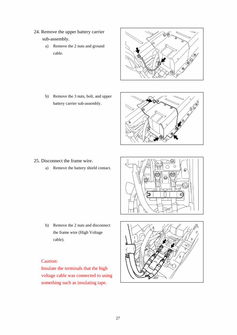
24. Remove the upper battery carrier sub-assembly.
a) Remove the 2 nuts and ground
cable.
b) Remove the 3 nuts, bolt, and upper
battery carrier sub-assembly.
25. Disconnect the frame wire. a) Remove the battery shield contact.
b) Remove the 2 nuts and disconnect
the frame wire (High Voltage
cable).
Caution: Insulate the terminals that the high voltage cable was connected to using something such as insulating tape.
27
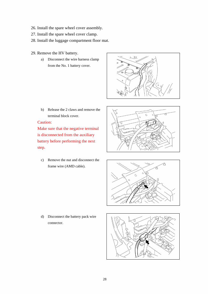
26. Install the spare wheel cover assembly. 27. Install the spare wheel cover clamp. 28. Install the luggage compartment floor mat. 29. Remove the HV battery.
a) Disconnect the wire harness clamp
from the No. 1 battery cover.
b) Release the 2 claws and remove the
terminal block cover.
Caution: Make sure that the negative terminal is disconnected from the auxiliary battery before performing the next step.
c) Remove the nut and disconnect the
frame wire (AMD cable).
d) Disconnect the battery pack wire
connector.
28
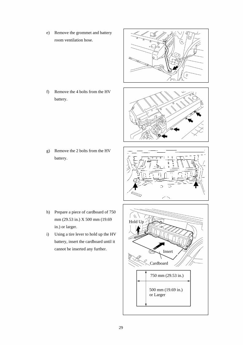
e) Remove the grommet and battery
room ventilation hose.
f) Remove the 4 bolts from the HV
battery.
Insert
Hold Up
Cardboard
750 mm (29.53 in.)
500 mm (19.69 in.) or Larger
g) Remove the 2 bolts from the HV
battery.
h) Prepare a piece of cardboard of 750
mm (29.53 in.) X 500 mm (19.69
in.) or larger.
i) Using a tire lever to hold up the HV
battery, insert the cardboard until it
cannot be inserted any further.
29
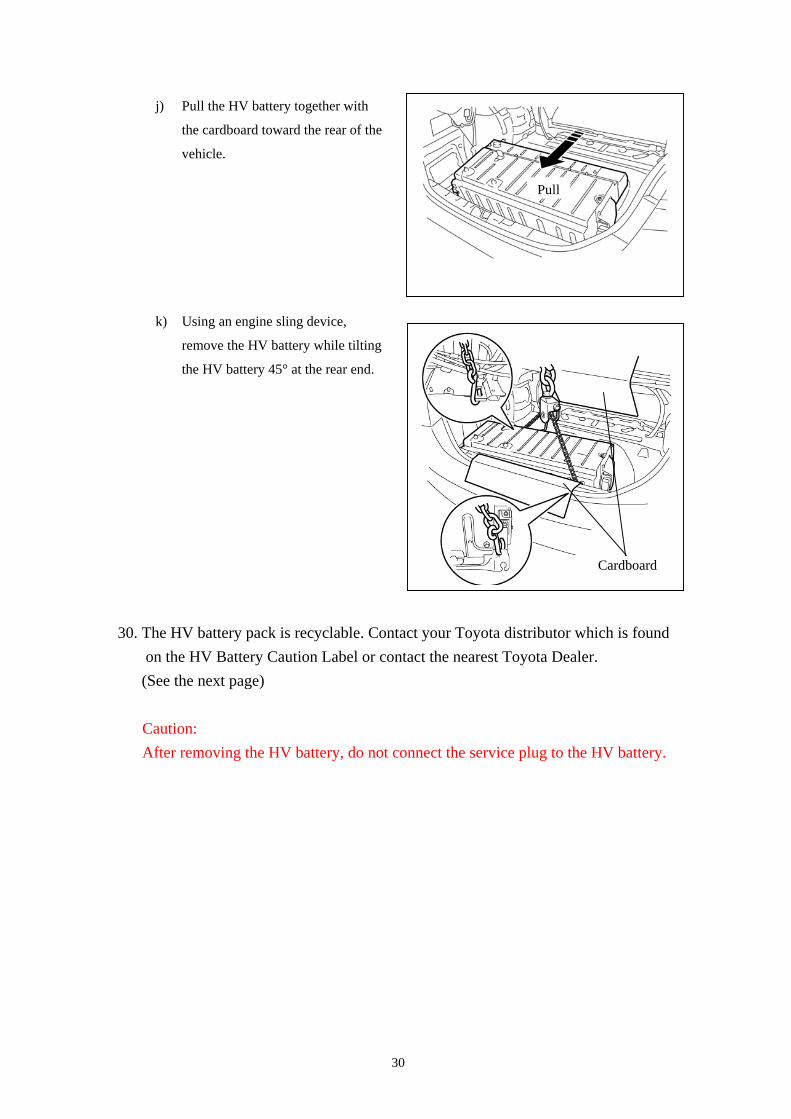
Pull
j) Pull the HV battery together with
the cardboard toward the rear of the
vehicle.
k) Using an engine sling device,
remove the HV battery while tilting
the HV battery 45° at the rear end.
Cardboard
30. The HV battery pack is recyclable. Contact your Toyota distributor which is found
on the HV Battery Caution Label or contact the nearest Toyota Dealer. (See the next page)
Caution: After removing the HV battery, do not connect the service plug to the HV battery.
30

HV Battery Caution Label
Hint: The label content may change due to regulatory revisions, etc.
1. 2007 to 2009 models for U.S.A.
2. 2010 model for U.S.A.
3. 2007 to 2009 models for CANADA
31
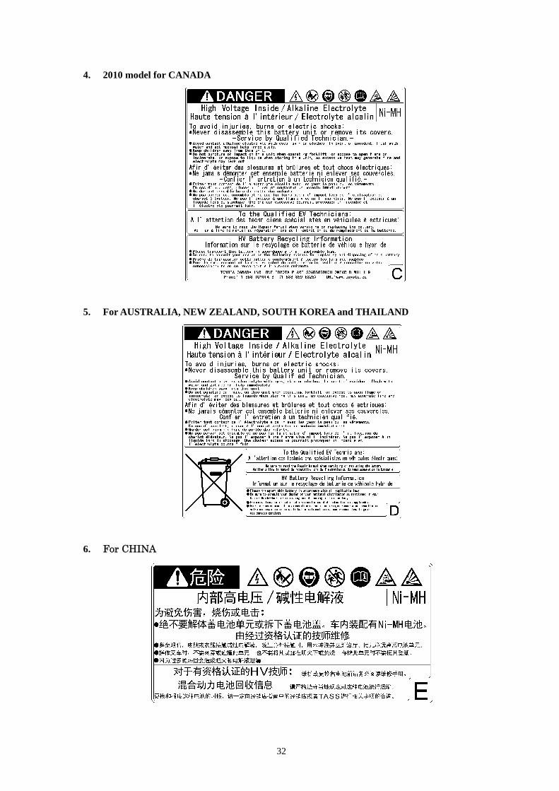
4. 2010 model for CANADA
5. For AUSTRALIA, NEW ZEALAND, SOUTH KOREA and THAILAND
6. For CHINA
32