Embed Size (px)
Citation preview
European Integrated Hydrogen Project [EIHP2]Contract: ENK6-CT2000-00442
GASEOUS HYDROGEN VEHICLEREFUELLING STATIONS
by WP 2: Refuelling Station Group
WP2 Group Members:Air Liquide: Jean-Yves Faudou; Laurent AllidieresAir Products: Peter BoutBP: Chris LoweDNV: Gerd Petra HaugomLinde: Jaco ReijerkerkNorsk Hydro: Henrik Anderson; Inger HugstmyrShell Hydrogen: James BarronVandenborre Hydrogen Systems: Christian Machens
2
Ref: Rev 3Date: 22 January 2004
WORKING DRAFT (Rev3)
GASEOUS HYDROGEN VEHICLE REFUELLING STATIONS
Background notes to the preparation of this WP2 Group Working Draft:1. The original Draft was prepared by J Barron (Shell Hydrogen BV) & C Lowe (BP/Bovis
Global Alliance), for discussion with members of the EIHP2 WP2 Group.
2. EIGA DOCUMENT IGC 15/96/E (Gaseous Hydrogen Installations) has been used as abasis for preparing the DRAFT. Approval has been received from EIGA to use theirmaterial. (EIGA Document IGC 15/96/E is a Copyright publication)
3. An EIHP2 WP2 Group Meeting was held 18 & 19 Sept 2002 in Amsterdam; Rev1incorporates comments and action items arising from that Meeting.
4. The intention of the Draft is to incorporate technical content for Gaseous HydrogenVehicle Refuelling Stations; eventual aim of Draft will be that it becomes the basis ofpreparing an ISO formatted Standard document.Approval for this Working Draft to be used for preparing an ISO formatted standarddocument was given at the EIHP2 Mid-term Meeting with the EC, October 2002 inBrussels.
5. Other Draft codes will be produced for Liquid Hydrogen vehicle refuelling stations oncethe code for gaseous hydrogen vehicle refuelling stations has been circulated.
6. The revision 2 is based on comments from the WP2 Working Group Meeting inAmsterdam, 22-23 May 2003. Rev 2 was placed on the EIHP2 Members web page forcomment by EIHP2 Members.
7. The revision 3 is based on comments and amendments made by the WP2 Working Groupat the meeting in Sassenage, 9 Sep 2003. Comments received from EIHP2 Membersfollowing the placement of Working Draft (Rev 2) on the EIHP2 Members web page,were discussed and incorporated.It is the intention of the WP2 Group to place the Working Draft (Rev 3) on the EIHP2Public web page for open Public Comment.
Reference Codes & Standards used to prepare this Draft (Rev 3):• EIGA Document IGC 15/96/E – Gaseous Hydrogen Installations• NFPA 50A – Standard for Gaseous Hydrogen Systems at Consumer Sites (1999 Ed)• German TRG 406 (Draft) regulations: Refuelling stations for Pressurised Gases (includes
CGH2)• ISO/PDTR 15916 – Basic considerations for the safety of hydrogen systems
3
TABLE OF CONTENTS
Introduction
1 Scope
2 References
3 Terms & Definitions3.1 Refuelling Stations for Pressurised Gas3.2 Hydrogen Pressure Vessels3.3 Pressurised Gaseous Hydrogen3.4 Storage Vessels3.5 Buffer Vessels3.6 Dispenser Units3.7 Measuring, Control and Monitoring Equipment3.8 Mechanically Actuating Safety Equipment3.9 Operating Area – vehicle refuelling3.10 Flammable Atmosphere3.11 Area Classification3.12 Hot Work
4 Properties of Hydrogen Gas7.1 General7.2 Potential Hazards7.3 Hazardous Risk Scenarios
5 General Design Features5.1 Design5.2 Hazardous Areas & Zones5.3 Electrical equipment and safety5.4 Location of Gaseous Hydrogen Vehicle Filling Stations5.5 Above ground buildings and enclosures for gaseous Hydrogen Vehicle Filling Stations5.6 Underground storage systems5.7 Pipelines5.8 Pipelines in trenches with electrical cables5.9 Venting, Pressure Relief and Venting Discharge Devices5.10 Materials5.11 High Pressure Connections5.12 Instruments
6 Safety Isolation Distances and Hazard Zones6.1 Minimum Recommended Safety Distances6.2 Hazardous Areas and Zones – Definitions6.3 Identification of and access to Hazard Zones of Above Ground Installations
7 Compression7.1 Definition7.2 Control and Monitoring Equipment
4
8 Purification8.1 Definition8.2 Gas Drying8.3 Filters and Separators
9 Hydrogen Vehicle Refuelling Stations9.1 Gaseous Hydrogen Vehicle Refuelling in existing public fuel stations9.2 Special considerations for operation of hydrogen vehicle refuelling stations9.3 Public refuelling of hydrogen vehicles9.4 Security9.5 Location of refuelling stations
10 Hydrogen Transfer10.1 Equipment10.2 Valves
11 Venting11.1 General11.2 Emergency venting of hydrogen systems11.3 Vent pipe
12 Dispensing Unit12.1 General12.2 Pressure Control Valves12.3 Requirements regarding protective housings12.4 Flexible Refuelling Hose
13 Electrical Equipment and Installations13.1 Electrical Standards13.2 Electrical Installation13.3 System Earthing13.4 Personnel Instruction13.5 Inspection13.6 Static Electricity
14 Fire Protection14.1 General14.2 Fire Fighting Equipment14.3 Action in Event of Fire
15 Personnel Protection Training15.1 Personnel15.2 Training
16 Commissioning16.1 Testing16.2 Purging16.3 Start-up16.4 Operation

5
17 Maintenance and Repairs17.1 Documentation17.2 Records17.3 Schedules17.4 Flexible Hoses
APPENDICESAppendix A: Flow diagrams of Typical Hydrogen Vehicle Refuelling Stations
Appendix B: Emergency Notices
Appendix C: Hazardous Area Diagrams
6
Introduction
This document has been prepared for the guidance of designers and operators of gaseous hydrogenvehicle refuelling stations. It is considered that it reflects the best practices currently available. Itsapplication will achieve the primary objective of improving the safety of gaseous hydrogen vehiclerefuelling station design and operation.
A gaseous hydrogen vehicle fuel dispensing station is an installation where gaseous hydrogen istransferred, under pressure, from a compression system via a dispenser and a refuelling connectioninto cylinders permanently mounted on a motor vehicle.
The hydrogen supply for the compression system may come from on-site generation of gaseoushydrogen or trucked-in gaseous or liquid hydrogen supply sources, or delivered from pipeline.
1 Scope
For the purpose of this guideline, a gaseous hydrogen vehicle refuelling station is a configuration ofthe following applicable assemblies:
• system for pressurising gas• purification• buffer storage• dispenser to dispense compressed gaseous hydrogen (CGH2) into vehicles.
The requirements of this guideline are not intended to constrain innovation. When consideringmaterials, designs or constructions not specifically dealt with in this guideline, these alternatives shallbe evaluated as to their ability to yield levels of safety and performance equivalent to those prescribedby this standard.
Exclusions:It does not include on-site production or supply of H2, transport or distribution of hydrogen, nor doesit cover any safety aspects in the use and application of the gas in technical or chemical processes.Hydrogen generation appliances that use water electrolysis or hydrocarbon fuel processingtechnologies are excluded from the scope of this standard.
2 References
This guideline incorporates by dated or undated reference, provisions from other publications. Thesereferences are cited at the appropriate places in the text and the publications are listed hereafter. Fordated references, subsequent amendments to or revisions of any of these publications apply to thisstandard only when incorporated in it by amendment or revision. For undated references the latestedition of the publication applies.
ISO/PDTR 15966: Basic considerations for the safety of hydrogen systemISO 14687: Hydrogen fuel – Product specificationIEC 60079-14:2002 Electrical Apparatus for Explosive Gas AtmospheresIEC 60079-17: 1996 Electrical Apparatus for Explosive Gas AtmospheresEN 1050 Safety of Machinery – Principles of Risk AssessmentEN 1070, Safety of machinery – TerminologyIEC 60034 Rotating electrical machinesIEC 60034-1 Rotating electrical machines – Part 1: Rating and performance

7
IEC 60034-5 Rotating electrical machines – Part 5: Classification of degrees of protection provided byenclosures of rotating electrical machinesIEC 60079-10 Electrical Apparatus for Explosive Gas Atmospheres — Part 10: Classification ofhazardous areasIEC 60204-1 Electrical Equipment of Industrial Machines — Part 1: General requirementsIEC 60364-4-41 Electrical protection of buildings – Part 4: Protection for safety – Chapter 41:Protection against electric shockIEC 60529 Degrees of protection provided by enclosuresIEC 60704-3 Test Code for the Determination of Airborne Acoustical Noise Emitted by Householdand Similar Electrical Appliances Part 3: Procedure for Determining and Verifying Declared NoiseEmission Values First Edition; CENELEC EN 60704-3IEC 60812 Analysis techniques for system reliability – Procedure for failure mode and effects analysis(FMEA)IEC 61025 Fault tree analysis (FTA)IEC 61508, Functional safety of electrical/electronic/programmable electronic safety-related systemsIEC 61511 Functional Safety: Safety Instrumented for the Process Industry Sector - Part 3: Guidelinesin the Application of Hazard and Risk AnalysisIEC 61882, Hazard and operability studies (HAZOP studies) - Application guideIEC Guide 104:1997 The preparation of safety publications and the use of basic safety publicationsand group safety publicationsISO 10440-1 Petroleum and natural gas industries — Rotary-type positive- displacement compressors— Part 1: Process compressors (oil-free)ISO 13707 Petroleum and natural gas industries – Reciprocating CompressorsISO 13850 Safety of machinery — Emergency stop — Principles for designISO 4898: Labelling and marking of productsISO TS 16528 Boilers and pressure vessels -- Registration of codes and standards to promoteinternational recognitionISO/IEC Guide 51:1999, Safety aspects – Guidelines for their inclusion in standardsISO/IEC Guide 7:1994, Guidelines for drafting of standards suitable for use for conformity assessmentANSI B31.3 Code for Pressure Piping in Chemical Plant and Petroleum Refinery EquipmentATEX directive 94/9/EC regarding electrical apparatus in an explosive areaPED directive 97/23/EC regarding pressure vesselsEN 50014 to EN 50020
3. Terms & Definitions
For the purposes of this guideline, the following terms and definitions apply:
3.1 Refuelling Stations for Pressurised GasRefuelling stations for pressurised gas are installations in which pressurised gas is filled intopressurised-gas tanks on vehicles. Forming part of the pressurised gas refuelling station is theequipment that serves in the operation of the station (e.g. conveying and dispensing plant, bufferstorage vessels).
3.2 Hydrogen Pressure VesselsHydrogen pressure vessels are containers for compressed pressurised gases that provide the fuel forvehicles and are essential components of the vehicles and are permanently installed in the vehicles.
3.3 CompressorA hydrogen compressor is a device that raises the pressure of incoming hydrogen to a higher value
3.4 Storage VesselsPressure vessels, from which the compressed gas is to be drawn off and pressurised, as well as therelated equipment, do not form part of the refuelling station.
8
3.5 Buffer VesselsBuffer vessels are pressure vessels that hold and supply the pressurised gas that has been compressedby the delivering equipment.
3.6 Dispenser Units
3.6.1 Dispenser UnitsDispenser units are those parts of the pressurised-gas refuelling station via which the pressurised gas isdispensed to refuel vehicles. They include, for example, the dispenser cabinet, containing asapplicable, a gas flow meter, flexible refuelling hose and vehicle refuelling nozzle attachments.
3.6.2 Dispenser cabinetDispenser cabinet is a protective housing to enclose applicable metering and associated equipment.
3.6.3 Refuelling Nozzles (Snap-on Couplings)Refuelling nozzles are connectors that are designed to provide a gas tight connection between theconnection point on the vehicle and the pressurised-gas refuelling station..
3.7 Measuring, Control and Monitoring Equipment
3.7.1 Measuring, Control and Monitoring Equipment for fuel dispensing operation.Measuring, control and monitoring equipment is equipment that is intended to automatically operatethe station within its approved range. The automation functions of measuring, controlling andmonitoring plant operations, shall include reporting and recording functions, as applicable.The operating equipment for measuring, control and monitoring shall determine the quantity of thedispensed hydrogen to meet any set outputs, and the safe operation of equipment.
3.8 Mechanically Actuating Safety Equipment
Mechanically actuating safety equipment prevents refuelling station operation outside acceptablemaximum or minimum operating pressures or prevents a gas leakage in the event of an incident. Thissafety equipment shall function without external power. For example: spring-loaded safety valve,breakaway coupling.
3.9 Operating Area – vehicle refuelling
The operating area is that area which can be reached by the dispenser’s refuelling nozzle, when usedunder normal working conditions at normal horizontal operating level, plus 1 m (see Appendix C).
3.10 Flammable atmosphere
A flammable atmosphere is a mixture of flammable gas with air in such proportion that, without anyfurther admixture, it will burn when ignited. In the context of area classification, the term flammableis synonymous with ‘explosive’.
3.11 Area Classification
Area classification is the assessed division of an installation into hazardous areas and non-hazardousareas, and the subdivision of the hazardous areas into zones.
3.11.1 Hazardous Area and Zone (Potentially Explosive Areas)Hazardous areas and zones are areas in which there can be expected to be an explosive or flammablegas atmosphere, and be expected to be present at such frequencies as to require special precautions forthe construction and use of electrical apparatus. All other areas are referred to as non-hazardous in this

9
context though they may, in part or whole, form part of a wider restricted area within the refuellingstation in which work is carried out under control conditions.
Hazardous areas are subdivided into zones as follows:(In pressurised-gas refuelling stations, Zone 1 and Zone 2 may occur, whereas Zone 0 will not occur).Zone 1:An area in which an explosive atmosphere, as a mixture of air and flammable gas, may build upoccasionally under normal operating conditions.
Zone 2:An area in which an explosive atmosphere, as a mixture of air and flammable gas, does not usuallyoccur or, if so, then only briefly, under normal operating conditions.
3.12 Hot Work
Hot work includes, e.g. work with an exposed flame, using electrical apparatus which is not explosion-proof, or working with devices which are not substantially non-sparking.
4. Properties of Hydrogen Gas
4.1 General
Hydrogen is colourless, odourless, tasteless, flammable and non-toxic. It is a gas at ambienttemperatures and pressures and is lighter than air, which means that it has the tendency to rise anddiffuse rapidly when released into the atmosphere, dependant on the direction, rate and pressure of therelease. Hydrogen can also diffuse rapidly through certain porous materials or systems that wouldnormally be gas tight with respect to air or other gases. Hydrogen is highly flammable and veryeasily ignition.
4.2 Potential Hazards
The primary risk with hydrogen is fire and explosion.
4.2.1 Flammable Properties
Hydrogen is extremely flammable in air with very wide limits (4-75% Vol in air), in oxygen andoxidants, and has an extremely low ignition energy. In practice, hydrogen venting or leaking toatmosphere, particularly from a pressure source, is very likely to ignite due to electrostatic or ignitionby particulates in the hydrogen.
Confined mixtures of hydrogen and air/or oxygen explode violently and may detonate. However,unconfined gas cloud explosions are considered very unlikely.Hydrogen burns in air with a very hot, pale blue, almost invisible flame that emits very little radiantheat and therefore gives little warning of its presence. Hydrogen flames, being extremely difficult toextinguish, can only be extinguished by isolating the hydrogen source.
4.2.2 Chemical Properties
Hydrogen is fundamentally a reducing agent but is not significantly reactive with many compounds. Itcan form violent or explosive reactions with some compounds (e.g. halogens and their compounds).Mixtures of hydrogen and organic vapours can ignite or explode upon contact with finely dividedRaney nickel, palladium or platinum in the presence of oxygen. Hydrogen should also be kept awayfrom oxidising agents.

10
4.2.3 Toxicological Properties
Gaseous hydrogen colourless, odourless and tasteless, it is not detectable by the human senses.Hydrogen is non-toxic but can act as an asphyxiant by displacing oxygen in the surrounding air.Symptoms of exposure may include headache, fatigue, increased breathing rate, dizziness, lack ofmuscular co-ordination, nausea, vomiting and loss of consciousness, coma or even death. The amountof hydrogen needed to present this risk is much higher than the lower flammable limit, and might onlybe a danger in confined spaces like tanks and vessels.
4.3 Hazardous Risk Scenarios
In the event of a release of hydrogen, there are a number of potential risk scenarios:
1) Dispersion of hydrogen (followed by ignition)2) Explosion of hydrogen (followed by a jet flame)3) Instant ignition with resultant jet flame
4.3.1 Dispersion of Non-Ignited Hydrogen
Depending on the pressure of release, weather conditions and the size of the smallest internal diameterof pipe work, hydrogen will disperse within its flammable range for several metres from the release.Tests have shown that this can range from 6 to 12 m.
4.3.2 Instant Ignition of Hydrogen
In this instance, a narrow jet flame will be produced. Calculations for a 2.9 mm diameter orificereleasing hydrogen at 200 bar show that a flame length of 5.7 m and 0.9 m diameter will result, withthe thermal flux falling below the 5 kW/m2 threshold level at 8.7 m from the leak.Larger orifices may lead to larger flame lengths depending on release pressure.
The potential effects of thermal radiation on the surrounding areas, and on people should beconsidered. Such data is useful in evaluating safe distances for sensitive locations (e.g. position ofsafety equipment such as fire hydrants, emergency assembly points, occupied buildings etc).
NB: A jet flame impinging on a hydrogen gas cylinder may heat the cylinder to such a temperaturethat the pressure rises to the point of rupture. In the event of a fire there is therefore a need to coolsurrounding cylinders with water.
5. General Design Features
5.1 Design
Hydrogen vehicle refuelling systems shall be designed, fabricated and tested in accordance withrecognised national pressure vessel and piping codes, and where appropriate, in accordance withstatutory requirements and risk assessments.
5.2 Hazardous Areas and Zones
When not covered by hazardous areas and zones given in Appendix C, zoning of potentiallyflammable areas shall be carried out according to EN 60079-10.Examples of hazardous areas and zones are given in Appendix C.
11
5.3 Electrical equipment and safety
Electrical equipment located in areas where flammable gas may be present, shall be suitable for thearea classification.Electrical safety shall ensure protection against shock, fire and burns during operation and routinemaintenance activities.Electrical equipment shall, as applicable, conform to the local or national codes.
5.4 Location of Gaseous Hydrogen Vehicle Filling Stations
Gaseous hydrogen filling stations shall be appropriately designed for installation in the followinglocations:
• Open air• Within buildings or enclosures• Below ground
They shall be located so that they are readily accessible for product supply and distribution vehicles,fire fighting services and provide easy means for escape of personnel in the event of an emergency.
They shall not be located beneath high voltage power lines.
Care shall be exercised with regard to their location relative to sources of fuel, such as pipelines orbulk storage containing other flammable gases or liquids; or other potential hazardous substances thatcould jeopardise the integrity of the installation.
Safety distances - see Table 1.Consideration shall be given to the proximity of other activities or buildings containing processequipment, where there is a potential fire or explosion hazard.
Precautions, such as the erection of safety barriers or fences, shall be taken to protect against damageduring the manoeuvring of any hydrogen supply unit and by unauthorised tampering.
5.5 Above ground buildings and enclosures for Gaseous Hydrogen Vehicle Filling Stations
5.5.1 Basic requirements for buildings and enclosuresBuildings in which hydrogen systems are installed shall be of single storey construction, be designedfor the purpose and be well ventilated with outlets at the high points.
The degree of enclosure should be minimum consistent with providing a reasonable workingenvironment in relation to local weather conditions.
Adequate measures shall be taken to ensure that hydrogen cannot penetrate into service ducts,electrical wiring, electrical conduits, staircases and passages that connect to locations that aredesignated as safe areas, i.e. outside the hazard zone (see Section 6).
Buildings used for hydrogen operation shall be of fire resistant construction as determined by nationalcodes or regulations. Provision of means of escape shall comply with Section 13.
Doors that do not have direct access to the outside shall be of fire resistant construction and shall beself-closing.
Explosion relief shall be provided only in exterior walls or roof and should be designed in such a waythat if an explosion occurs, the resulting pressure will be relieved without the explosion relief systememitting dangerous projectiles.
12
The total relieving area should not be less than either the area of the roof or the area of one of thelongest sides. This area may consist of any one or a combination of the following:
• Area open to the outside• Outward swing doors in exterior walls• Lightly fastened hatch covers• Light roof design
Lighting shall be provided of adequate intensity for all enclosures and operating areas so that, at alltimes operations can be carried out in safety. The lighting equipment shall be suitable for use inhydrogen areas (see Section 15).
5.5.2 Heating buildings or enclosuresWhere heating is required, it should preferably be by hot water or warm air. Where recirculatorysystems are used, consideration shall be given to the possibility of hydrogen contamination andadequate precautions shall be taken. The heat sources shall be located remote from the buildings andcomply with the distances specified out in Table 1. Where an electrical source for heating is used, itshall comply with the requirement for electrical equipment outlined in Section 15.
5.5.3 VentilationThe building or enclosure shall have good low and high-level natural ventilation to the open air. Outletopenings shall be located at the highest point of the room in exterior walls or roof.
In areas where natural ventilation is not possible, consideration shall be given for the installation ofpermanent atmosphere analysis equipment with suitably located point(s), and /or forced ventilation.
5.6 Underground storage systemsComment made for further discussion: The WP2 Group supported the need to include within theworking Draft of ‘hydrogen underground storage systems’, but the members had insufficientknowledge and experience to compete a draft clause within the set EIHP2 Project timelines.
5.7 Pipelines
Aboveground pipelines for hydrogen shall be clearly identified by means of colour coding and/orlabels.
Isolation valves shall be provided so that the hydrogen source can be shut off safely in the event of anemergency. This is particularly important where hydrogen pipelines enter buildings or enclosures.Pressure relief devices shall be provided to prevent over pressure in blocked-in lines where this canoccur.
Equipment and pipeline systems, where necessary, shall be earthed and bonded to give protectionagainst the hazards of stray electrical currents and static electricity.
Above ground or exposed pipe work shall be protected from corrosion, adequately supported andprotected from mechanical damage.Buried pipe work shall be continuously welded and protected with a system to prevent external pipesurface corrosion. The pipe work shall be laid at a depth to protect it against mechanical damage. Thepipe work should be buried in trenches a minimum 600 mm deep and/or subject to topographicalinvestigation and/or local regulations. Warning tapes and/or protection slabs should be placed abovethe pipe work.Any cathodic protection system should not cause interference to any other underground structure.NB: Check for any local legislative/statutory requirements for cathodic protection of buried pipe work.
13
WP2 Group comments made for further discussion:• Specific cathodic protection of a complex construction is a very specialised activity. Two
standards should be cited. The first general EN 12 954, "Cathodic protection of buried orsubmerged metallic structures" and the other is still under approval prEN 13636 "Cathodicprotection of buried metal tanks and related piping" which entirely falls within the scope.
• Discussions are currently continuing on the contradiction between Cathodic Protection andthe protection of personnel which necessitates putting metal structures into the ground whichis contrary to efficient cathodic protection
5.8 Pipelines in trenches with electrical cables
Where it is necessary to run hydrogen pipelines in the same duct or trench used for electrical cablesand other pipelines, then all joints in the hydrogen pipelines in the ducted/trenched section shall bewelded or brazed.A minimum separation distance of 50 mm from electrical cables and any other pipelines shall bemaintained.The hydrogen pipeline should be run at a higher elevation than other pipelines, unless localrequirements stipulates otherwise.
5.9 Venting, Pressure Relief and Venting Discharge Devices
The vents of pressure relief devices shall be designed or located so that moisture or contaminantscannot collect and freeze in a manner that could interfere with the proper operation of the device.
The vent discharge piping should be securely supported and designed for the pressure arising withinthe vent, or for at least a nominal pressure of 10 bar. Vent lines shall not be fitted with flame arresters,or any other restrictions that prevent the free release of hydrogen to the atmosphere.Copper alloys or stainless steel are preferred materials to use for discharge vents to minimise thepossibility of ignition due to atmospheric corrosion particles.
Vents, including those of pressure relief devices, shall be arranged to discharge in a safe place in theopen air so as to prevent impingement of escaping gas on to personnel or any structure, vessels, valvesor fittings. Vents should be piped individually, manifolding is not recommended. Vents shall notdischarge where accumulation of hydrogen can occur, such as below the eaves of buildings.
5.10 Materials
All materials used shall be suitable for hydrogen service and for the pressures and temperaturesinvolved.
Cast iron pipe and fittings shall not be used. The use of any casting is not recommended due to thepermeability of hydrogen and the possibility of porosity in the casting.
Pipes and fittings shall conform to an established standard or specification for their manufacture.
Pressure vessels, such as those used for buffer storage, that are made of materials that are subject tocorrosion by atmospheric conditions, shall be protected by corrosion prevention methods.The operator’s attention is drawn to the importance of avoiding corrosion that can otherwise limit theworking life of the cylinders and affect the fatigue characteristics in serious cases. The implementationof good periodic preventative maintenance in anti-corrosion procedures is strongly recommended.
The use of dissimilar metals in tubing, fittings and other components should be avoided. Stainless steelfittings shall be compatible with metal tubing materials. Care shall be taken in contacts betweendissimilar metals for corrosion protection. Special consideration shall be given to prevent contactbetween small components of less noble metals to larger more noble ones.
14
Note: “Dissimilar metals” can also include different alloys of stainless steel.
Under certain conditions, some high tensile ferrous materials are susceptible to hydrogenembrittlement. Due considerations shall be given when selecting ferrous materials for hydrogenservice.Further information on the selection of materials, particularly choice of steels resistant to ‘HydrogenEmbrittlement Corrosion’ is found in ISO/PDTR 15916 App C and ISO/DIS 11114, Part 1 and 4
Where ammonia is likely to be present as an impurity, or as an atmospheric contaminant, copper andcopper/tin/zinc base alloys shall not be used for pipe or fittings since these materials are susceptible tobe attacked by ammonia. Consideration should also be given to the possibility of other contaminantsbeing present and adequate precautions be taken.
5.11 High pressure connections
It is recommended that joints in piping and tubing should be made by welding, brazing or by flangedconnections. Where breakable joints (threaded, flanged etc.) are considered necessary, these should bekept to a minimum since they are a potential source of leakage. Particular care shall be taken in the useof such connections due to the permeability of hydrogen at all pressures
The use of compression fittings, ferrous or nonferrous, is not preferred. Where it is considered thatcompression fittings are necessary in the design of the system (such as small bore lines) then strictobservance of the manufacturers' instructions for use and fitting shall be followed; includingcompliance with tightening up procedures.Pipe fittings , which can cut into the pipe wall, reducing wall pipe thickness, shall not be used.
Electrical continuity or earthing shall be maintained throughout the system, unless a cathodicprotection system has been installed for corrosion protection of underground pipe work (see Section12.3).
5.12 Instruments
Instruments and gauges shall be designed and located such that, in the event of a leakage or rupture,and possible subsequent fire, the risk to personnel is minimised. The use of safety glass and blow-outbacks on pressure gauges is recommended.
5.12.1 Hydrogen Gas and Fire Detection InstrumentsIf hydrogen gas detection instruments are provided for detection of gas leaks or a hydrogen fire thefollowing guidance is given (see also ISO/PDTR 15916):Fire detection:
• Infrared detection devices will not pick–up the existence of a hydrogen fire.• Only UV based detection methods will indicate the presence of a fire, however, if they are
located externally from buildings or enclosures they can easily confused by the presence ofwelding activities even at a long distance away. Also direct sun light or sun light reflectionsmay cause false alarms.
Gas detection:The correct placement of a gas detector is critical to its ability to perform.Limitations:
• Gas detectors indicate conditions at a particular location only• Problem of ever changing air currents within a room or outdoors from wind direction• Fixed detectors can have a slow response eg 10% LEL is measured at the detector,
100% LEL may exist at the leak• Does not detect fire• Hand held detector is needed to find leaks
15
6 Safety distances and hazard zones
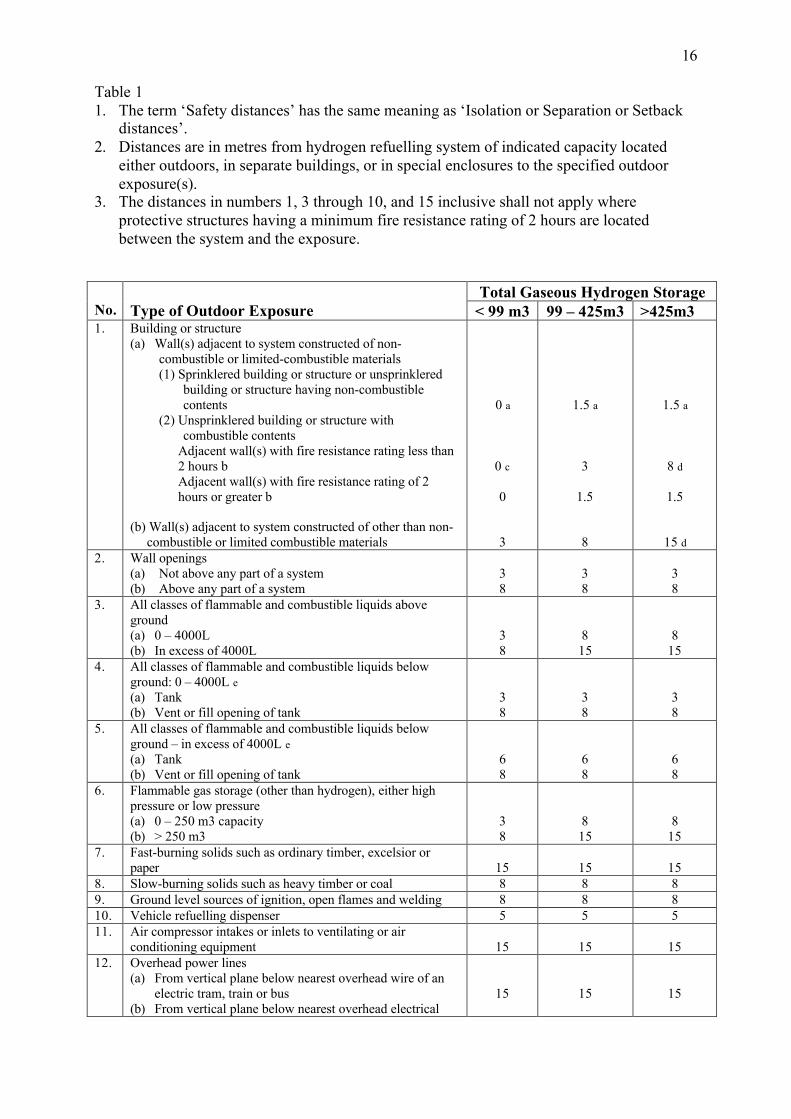
6.1 Minimum Recommended Safety DistancesHydrogen vehicle filling stations shall be surrounded by safety distances and hazardous zones.The extent of these zones is given in Table 1. The distances are measured from those points inplan view at which, in the course of operation, an escape of hydrogen may occur. Whereequipment is installed within buildings or enclosures, the distances to outside types ofexposure are measured from the openings, e.g. windows, doors etc.
Pipelines that contain valves, flanges, removable connections etc. shall be considered assources of hydrogen escape only at the points where such joints and connections occur.
The distances given in Table 1 may be reduced by the provision of suitable fire resistantbarrier walls or by other safety features determined by a risk analysis. The type anddimensions of the barrier and the distance reduction achieved will be determined by theconditions at the source of hydrogen and the nature of the exposure.
Activities other that those directly related to the hydrogen operation should be kept remotefrom hydrogen equipment.
The distances given in Table 1 are the minimum recommended.All electrical equipment within a building or enclosure, where there is a possible source ofhydrogen escape, and within the distance specified in Table 1, shall be of an approved type inaccordance with existing recognized national or international standards or local regulations.Such approved equipment shall not be considered as a source of ignition.
Comment from WP2 Working Group: H2 Safety studies are presently being carried out bySandia Labs for the US DOE. Safety distances in Table 1 could change depending on theoutcome of these studies.
16
Table 11. The term ‘Safety distances’ has the same meaning as ‘Isolation or Separation or Setback
distances’.2. Distances are in metres from hydrogen refuelling system of indicated capacity located
either outdoors, in separate buildings, or in special enclosures to the specified outdoorexposure(s).
3. The distances in numbers 1, 3 through 10, and 15 inclusive shall not apply whereprotective structures having a minimum fire resistance rating of 2 hours are locatedbetween the system and the exposure.
Total Gaseous Hydrogen StorageNo. Type of Outdoor Exposure < 99 m3 99 – 425m3 >425m31. Building or structure
(a) Wall(s) adjacent to system constructed of non-combustible or limited-combustible materials(1) Sprinklered building or structure or unsprinklered
building or structure having non-combustiblecontents
(2) Unsprinklered building or structure withcombustible contents
Adjacent wall(s) with fire resistance rating less than2 hours bAdjacent wall(s) with fire resistance rating of 2hours or greater b
(b) Wall(s) adjacent to system constructed of other than non-combustible or limited combustible materials
0 a
0 c
0
3
1.5 a
3
1.5
8
1.5 a
8 d
1.5
15 d2. Wall openings
(a) Not above any part of a system(b) Above any part of a system
38
38
38
3. All classes of flammable and combustible liquids aboveground(a) 0 – 4000L(b) In excess of 4000L
38
815
815
4. All classes of flammable and combustible liquids belowground: 0 – 4000L e(a) Tank(b) Vent or fill opening of tank
38
38
38
5. All classes of flammable and combustible liquids belowground – in excess of 4000L e(a) Tank(b) Vent or fill opening of tank
68
68
68
6. Flammable gas storage (other than hydrogen), either highpressure or low pressure(a) 0 – 250 m3 capacity(b) > 250 m3
38
815
815
7. Fast-burning solids such as ordinary timber, excelsior orpaper 15 15 15
8. Slow-burning solids such as heavy timber or coal 8 8 89. Ground level sources of ignition, open flames and welding 8 8 810. Vehicle refuelling dispenser 5 5 511. Air compressor intakes or inlets to ventilating or air
conditioning equipment 15 15 1512. Overhead power lines
(a) From vertical plane below nearest overhead wire of anelectric tram, train or bus
(b) From vertical plane below nearest overhead electrical15 15 15

17
power or telephone line 1.5 1.5 1.513. Places of public assembly 8 15 1514. Public sidewalks and parked vehicles (excluding vehicles
being refuelled) 5 5 515. Line of adjoining property that can be built upon 1.5 1.5 1.5
Notes to sub-letters in Table 1:a: Portions of wall less than 3m (measured horizontally) from any part of a system shall have
a fire resistance rating of a least ¼ hourb: Exclusive of windows and doors (see number 2 of Table 1)c: Portions of walls less than 3m (measured horizontally) from any part of a system shall
have a fire resistance rating of a least 1 hourd: But not less than ½ the height of adjacent wall or building or structuree: Distances can be reduced to 5m for Class IIIB combustible liquids
6.2 Hazardous Areas and Zones
6.2.1 Definitions
1. Area Classification
Area classification is the assessed division of an installation into hazardous areas and non-
hazardous areas, and the subdivision of the hazardous areas into zones.
2. Hazardous Areas and Zones
Hazardous areas and zones are areas in which there can be expected to be an explosive or
flammable gas atmosphere, and be expected to be present at such frequencies as to require
special precautions for the construction and use of electrical apparatus. All other areas are
referred to as non-hazardous in this context though they may, in part or whole, form part of a
wider restricted area within the refuelling station in which work is carried out under control
conditions.
Hazardous areas are subdivided into zones as follows:
Zone 0: An area in which an explosive gas-air mixture is continuously present or present forlong periods.
Zone 1: An area in which an explosive gas-air mixture is likely to occur in normal operation.
Zone 2: An area in which an explosive gas-air mixture is not likely to occur and if it doesoccur, will only exist for a short time.
• Zone 0 does not occur in a gaseous hydrogen vehicle refuelling station.
• The area of zone 1 has to be permanently free of potential ignition sources (fire, "normal"electrical equipment, etc.). Electrical equipment installed in this area has to be certified tothe appropriate hazardous area rating.
• The area of zone 2 has to be temporarily free of potential ignition sources (fire, "normal"electrical equipment, etc.), i.e. during the actual filling process. Electrical equipmentinstalled in this area has to be certified to the appropriate hazardous area rating.

18
• The dispenser must not be located within the zone 1 area of the storage tanks or thecompressor system.
• The dispenser must be located in such a way that vehicles approaching the dispenser mustnot enter into the zone 1 or zone 2 areas of the storage tanks or the compressor system.
6.2.2 Compressor Planta) Indoor installation (contained within a building or enclosure):
i) Within the enclosed space: Zone 1ii) Outside the enclosed space: Zone 2
b) Installation within machinery housing:i) Within the housing: Zone 1ii) Outside the housing: Zone 2 extends:
• 20 cm from any opening, when a gas warning device connected to anemergency shut-off is provided within the housing;
• 2 m from any opening, if no gas-warning device is connected to an emergencyshut-off provided within the housing.
c) Outdoor installation – no machinery housing: Zone 2 extends 3 m around thecompressor unit
6.2.3 Gas Purification, Drying & Gas Storage Plant
a) Indoor installation:i) Within the enclosed space: Zone 2ii) Outside the enclosed space: non-hazardous area
b) Erection within protective walls or enclosures:i) Within the protective walls: Zone 2ii) Above the protective walls: Zone 2iii) Beyond the protective walls: non-hazardous area
c) Outdoor erection: Zone 2 extends 3 m around the plant
6.2.4 Dispensing Unit
a) Dispenser cabinet:i) Within the portion of the cabinet housing process piping: Zone 1ii) Within the portion of the cabinet sealed off from the portion of cabinet containing
process piping: Zone 2iii) Outside the cabinet housing: Zone 2 extends:
• 20 cm around unit• 1 m above unit
b) Hose and vehicle coupling:Operating area (length of hose + 1 m), unless vehicle filling area is restricted, in whichcase the operating area is defined by the designated filling area.
Refer to Appendix C for Hazardous Area Diagrams.
19
6.3 Identification of and Access to Hazard Zones of Above ground Installations
The extent of the hazard zones shall be indicated by permanent notices, particularly at access points, orby distinctive lines painted on the ground. Notices shall indicate the nature of the hazard in a locallanguage, e.g.
HYDROGEN - FLAMMABLE GASNO SMOKING - NO NAKED FLAMES
Only authorised personnel shall be allowed to enter these zones. These personnel shall be aware of thehazards likely to be encountered and the relevant emergency procedures.
Any work other than that directly connected with an operating station, shall be covered by a SafeWork Permit system.
7 Compression
7.1 General
All types of compressors are acceptable provided that they have been designed with particularreference to hydrogen service. Any vibrations from the compressor shall not be transferred to the pipework.Safety controls shall be installed to ensure temperature and pressure levels do not exceed or fall belowset operating levels.
7.2. Control and Monitoring Equipment
In addition to the instruments and controls normally provided for gas compressing systems, thefollowing specific safeguards for hydrogen shall be considered:
7.2.1 Inlet PressureThe inlet pressure shall be monitored by a pressure indicator/switch to avoid a vacuum in the inlet lineand consequent ingress of air. This pressure switch shall cause the compressor to shut down before theinlet pressure reaches atmospheric pressure.
7.2.2 Oxygen AnalysisWhere the hydrogen comes from a low pressure source, or there is a possibility of oxygencontamination, the oxygen content in the hydrogen shall be continuously measured. Should the oxygencontent reach a level of 1 %(vol), then the compressor shall be automatically shut down.
The location of the oxygen analyser may be either immediately before the suction inlet to thecompressor, which is preferred, or after the first stage discharge if the suction inlet pressure is notsufficient for the analyser.
7.2.3 Discharge TemperatureThe temperature after the final stage, or after cooler, where fitted, shall be monitored by anindicator/alarm that may be arranged to shut down the compressor at a predetermined maximumtemperature.
7.2.4 Discharge PressureThe pressure after the final stage shall be monitored by an indicator/alarm, which may be arrangedeither to shut down the compressor or, initiate alternative actions e.g. recycle at a pre-determinedmaximum pressure, which is below that of the final relief device.
20
7.2.5 Cooling WaterA water pressure/flow alarm shall be provided in the cooling water system, which may be arranged toshut down the compressor in case of low pressure of flow.
7.2.6 Purge Gas on Electrical EquipmentWhere the motor and auxiliary equipment are pressurised by an inert gas, e.g. nitrogen, lowpressure/flow shall be indicated by an alarm. This may be arranged to shut down the motor andauxiliaries.
7.2.7 Pressurised Crank CasesWhere the compressor crank case is pressurised by hydrogen or inert gas, low pressure/ flow shall beindicated by an alarm. This may be arranged to shut down the compressor.The compressor design shall exclude an air/H2 mix from forming in the compressor crankcase.
8 Purification
8.1 Definition
The purification system, if applicable, consists of equipment to remove oxygen, moisture and otherimpurities from the hydrogen.The system may comprise purification vessels, dryers, filters and separators.
8.2 Gas Drying
If adverse effects on the performance and/or corrosion are to be expected because of the quantity ofmoisture in the gas, it will be necessary to install a gas-drying apparatus to ensure that the gas shall bedried such as no condensate shall appear at the highest pressure at all operating conditions. .
8.3 Filters and Separators
Filters and, if applicable, separators shall be provided in pressurised-gas refuelling stations if the gas isexpected to contain function-impairing impurities (e.g. dust, liquids). The filters and separators shallbe dimensioned for the maximum gas flow and for the expected impurities in the gas, and shall beprovided with sufficiently large sumps or collecting tanks. As far as the apparatus is concerned, it isrecommended the filters and the separators to be combined in a single unit. It is desirable that thefilters have a specified separating capacity, e.g. according to DIN 3386 (refer in normative list).
Clogging of the filter insert in the main gas flow shall be monitored. This may be done by regularoperational checks or by monitoring equipment, e.g. differential-pressure gauges indicating amaximum value, as specified by the filter supplier. The filters and separators shall be arranged andinstalled in such a way that it is possible to open and empty them in a safe manner. In the event offrequent opening and closing operations, they are recommended to be fitted with quick opening andclosing fittings.
For removing liquids (condensation products), a manual or an automatic discharging device, ifapplicable comprising a sump, shall be provided.
21
9 Hydrogen vehicle refuelling stations
9.1 Gaseous Hydrogen Vehicle Refuelling in existing public fuel stations
It is permitted for the dispenser’s of gaseous H2 refuelling stations to be located within theoperating area of an existing public fuel station and a refuelling station for rail-bound vehiclesdelivering diesel fuel and fuel oil, subject to all plant complying with the highest hazardousarea zone in which it is located.
9.2 Special considerations for operation of Hydrogen Vehicle Refuelling Stations
In addition to the requirements contained elsewhere in this Code for hydrogen stations, thefollowing shall also apply to gaseous hydrogen vehicle fuel dispensing stations:
• Where the storage installation area is not under the direct control of authorised persons,it shall be contained within a secure, locked enclosure and the key held by an authorisedperson.
• Permanently installed vessels shall be provided with non-combustible supports on firmnon-combustible foundations. The installation should be located outside.
• Areas around the refuelling station including the vehicle forecourt paving shall be freefrom combustible materials
9.3 Public refuelling of hydrogen vehicles
Self-authorised hydrogen-dispensing systems including key code and card-locked dispensingsystems shall be limited to the filling of permanently mounted fuel containers on hydrogenpowered vehicles.In addition, the operator of a self-authorised hydrogen dispensing facility shall provide for thesafe operation of the system with the preparation of an emergency procedures plan, thetraining of employees and operators who use and maintain the system and provisions foremergency communications to local fire protection services.
See Appendix A for Flow Diagrams of typical vehicle refuelling stations.
9.4 SecurityAbove ground outside storage shall be protected from damage or unauthorised interference by meansof a security mesh steel fence of 1.8 m height minimum or equivalent structure surrounding thestorage equipment at 1 m distance from the plant and equipment.Above ground stations shall be protected from impact from manoeuvring vehicles where such impactis likely or probable, by a suitable kerb and or barrier/post
9.5 Location of refuelling stations
The preferred location for refuelling stations is specified to be outdoors above ground.Where compression and storage equipment are to be located in buildings or enclosures theconstruction material should be non-combustible with provision provided for explosion relief orventilation systems to be incorporated into the design.Compression and storage equipment located in underground vaults will incorporate adequateventilation systems identified by risk assessments to control the identified risk.
22
Refuelling stations shall be located on properties complying with safety distances specified in Table 1,except: Where a risk assessment can demonstrate safe design for operation with the proposed reduceddistances.
9.5.2 CanopiesGas storage and dispensing facilities may be protected from the effects of the weather by a roof orcanopy. Such a roof and structure shall be designed to facilitate the dispersion of free or escaped gas,and shall not permit gas to be trapped.Protection of storage facilities from the effects of weather is recommended.
9.5.3 Rooftop locationsGaseous hydrogen installations located on the roofs of buildings shall be supported on masonry,concrete, steel or other approved non-combustible construction provided that where such supports arelocated in the building, the supports shall be afforded a fire resistance rating of 2 hours, but not lessthan that required by the building type of construction.The roof assembly directly under such equipment shall also be afforded a fire resistance rating of 2hours but not less than that required by the building type of construction.
Approved signage in local language having 25 mm block letters shall be affixed in a conspicuouslocation on the building exterior stating: ROOF TOP HYDROGEN GENERATION AND/ORSTORAGE.
10 Hydrogen Transfer
10.1 EquipmentAll devices that are used in H2 installations shall be of a type and construction suitable for theirintended service.
10.2 Valves
10.2.1 Shut-off valvesA minimum number of 4 manually operated shut-off valves should be fitted between the gas storageunit and the vehicle filling nozzle except in those cases quoted below in 10.2.3 & 10.2.4)(Refer alsoAppendix A)Note: If a refuelling station has more than one outlet pipe from the storage to the dispensing point,then each supply line shall have the valve configuration described below.
10.2.2 Gas storage isolation valveEach gas storage unit shall have a quick action gas storage isolation valve installed in the supply pipeimmediately adjacent to its gas storage unit to enable individual shut off and isolation of each unit.These valves shall be located within the secure area of the installation.
10.2.3 Master shut-off valveA master shut-off valve shall be installed in the outlet pipe outside, but immediately adjacent to, thegas storage unit. This valve shall be capable of being locked off but not locked on. The valve shall be aquick action valve and shall be positioned outside by the secure area that surrounds the gas storageunit. The function of this valve is to isolate all downstream equipment from the gas storage unit.Note: In those refuelling stations where H2 vehicle refuelling is carried out only immediately adjacentto the gas storage unit, the master shut-off valve is acceptable as the emergency shut-off valve (see10.2.4)
10.2.4 Emergency shut-off valveA quick action, (quarter turn), emergency shut-off valve shall be installed on the steel outlet pipe andmust be in a readily accessible position to the vehicle refueller.This valve should be shut off when the refuelling station is unused.
23
Notes:• In public refuelling stations equipped with electronic dispensers the EMERGENCY SHUT-
OFF VALVE is usually the shut-off valve located on the dispenser.• In situations where the MASTER SHUT-OFF VALVE is not immediately accessible from the
forecourt, it is recommended that an additional emergency shut-off valve be fitted. This valveknown as the FORECOURT ISOLATION VALVE should be located on the forecourt butoutside the hazardous area created by the dispensing point.
10.2.5 Vehicle refuelling shut-off valveA vehicle refuelling shut-off valve shall be installed for each flexible vehicle refuelling hose andshould be located in the refuelling hose adjacent or incorporated with the nozzle. This vehiclerefuelling shut-off valve shall control the refuelling of the vehicle with H2 and shall have facilities forventing the flexible line between the valve and the vehicle nozzle. The vent is to allow the bleeding ofresidual high-pressure gas in the refuelling line after refuelling.
10.2.6 Valve identificationAll valves shall be suitable for the full range of pressure and temperature to which they may besubjected. The manufacturer shall stamp or otherwise permanently mark the valve body to indicateservice ratings. Other piping components such as filters, and connecting joints shall also be similarlymarked.The master shut-off valve and emergency shut-off valve shall be clearly labelled, by a label affixedthereto, with letters of not less than 20 mm height on a white or contrasted background. The valves orvalve labels should clearly indicate the direction of closing.
11.0 Venting
11.1 General
H2 systems shall be equipped with venting or bleed connections designed into transfer systems topermit depressurising any H2 supply line before dismantling for servicing.
11.2 Emergency venting of H2 systems
H2 systems shall be equipped with venting that will relieve excessive internal pressure.H2 systems shall not discharge inside buildings or enclosures. All portions of the system shall beprotected by pressure relieving devices.The pressure relief valve(s) on the H2 storage vessels shall be sized as a minimum to accommodate aH2 compressor that fails to shutdown or unload.
11.3 Vent pipeA vent pipe that will divert gas flow to atmosphere shall be installed on the installation for purgingpurposes. The vent shall be designed and constructed as follows:The piping shall be constructed of pipe or tube materials approved for H2 service in accordance withASME B31.3 or equivalent national standard, for the rated pressure, volume and temperature.The vent pipe shall be properly supported and shall be provided with a rain cap or other feature thatwould not limit or obstruct the gas flow from venting vertically upwardsA means shall be provided to prevent water, ice and other debris from accumulating inside the ventpipe or obstructing the vent pipe.
12 Dispensing Unit
12.1 General
A manually operated shut-off valve to isolate each dispensing unit shall be provided for maintenancepurposes.

24
In addition, a fail safe shut-off control valve must be provided in front the dispenser’s flexiblerefuelling hose, to close automatically as soon as the safe maximum filling pressure in the pressurised-gas cylinder of the vehicle is reached, or as soon as associated measuring, control and monitoringprotection equipment detects the safe maximum filling pressure. A filter must be fitted in front ofthese shut-off control valves.Dispensing units shall be erected in such a way that it will not be necessary for vehicle to drivethrough potentially explosive regions of other parts of the station, e.g. buffer storage vessels. It ispossible for dispensing units to be located next to those of petrol refuelling stations; their operatingareas may overlap. In this regard, see Appendix C.
Temperature-compensated measuring, control and monitoring equipment shall be provided in eachdispensing unit to automatically cut off further gas supply to the flexible refuelling hose when the safemaximum pressure of the filled gas, relative to +15°C, is reached in the pressurised-gas equipment ofthe vehicle. This maximum pressure may not exceed that maximum filling pressure of the pressurised-gas cylinder at a measured temperature of 85°C in the cylinder.
Hydrogen dispenser units shall be protected by a suitable barrier or mounted on a concrete plinth toprevent vehicle traffic from striking the unit.
12.2 Pressure Control DevicesThe maximum vehicle gas pressure during refuelling shall be controlled by pressure limiting devicesor systems as described as follows:
Normal operation. An automatic device that operates at the maximum allowable fill pressure andresets to permit the next refuelling cycle.
At least one independent pressure limiting devices or systems as follows:• Two independent electrical devices that shall be of fail safe design that shall operate at not
more than 10% above the maximum fill pressure.Operation of the fail-safe protection device shall cause the refuelling system to cease operationuntil manually reset. The manual reset shall be installed in a position that is not readily accessibleto operating personnel.• One mechanical pressure relief device set at 10% above the maximum fill pressure.Fuel transfer must be automatically interrupted when the vehicle fuel tank contains low-pressure(1 barg). Low tank pressure may indicate that the tank contains air. The pressure relief device mayhave leaked hydrogen out of the tanks and air may have diffused into the tanks.
12.3 Requirements Regarding Protective Housings
The protective housings of dispenser cabinets should meet the following requirements:Must be able withstand the expected service loadsThey must have adequate service durability and be made from flame-proof and anti static materialsRecommended thickness of protective housings of steel:1. A wall thickness of the covering panels is not less than:
a) 1 mm for sheet steel,b) 0,5 mm for rust-resistant sheet steel.
2. When inspection windows which are larger than 0,12 m2 or which are illuminated from within,consist of at least 4,5 mm thick laminated glass,
3. When inspection windows with a surface area up to 0,12 m2 and not illuminated from within,consist of 4 mm thick laminated glass.
The interior housing of the dispenser cabinet must be adequately naturally or force-ventilated. Whennaturally ventilated, two openings at least 100 cm2 in size, which are positioned on opposite sides andat different elevations, shall be provided. One opening must be positioned in the upper region of thehousing, another opening in the lower region, so as to ensure sufficient cross-ventilation. Pressurised
25
gases emerging from safety relief equipment must be able to be ventilated and dissipate in a safemanner.The dispenser shall be designed so as to prevent the release of any gas into the interior of the dispenserframe during any stage of vehicle refuelling operations.The structural foundation must be adequate to support all components including vehicles to berefuelled.The dispenser foundation should be level.
12.4 Flexible Refuelling Hose
12.4.1 GeneralFlexible hose shall only be used downstream of the emergency and isolation shut-off valve.The flexible hose shall be of, or lined with, materials that are resistant to corrosion and the actions ofany contaminants in the H2 gas. The material of construction shall provide the best possible resistanceto permeation. Where outer sleeves are fitted, these shall be suitably pierced to prevent inflation.The vehicle refuelling hose shall at all time be supported , to ensure against abrasion or kinks, and tofacilitate the easy withdrawal for use without contact with the ground. Provision shall be made for thesecurity of the refuelling shut-off valve when the station is unattended.The length of the flexible refuelling hoses should not be more than five and not less than three meters.The hose must be electrically conductive (to any specific specification?).The flexible hose shall be suitable for the most severe pressure and temperature service conditionsexpected with a burst pressure of at least 4 times (comment required) the maximum working pressure.Connections for the flexible hose shall be designed with a burst pressure of at least 4 times the mostsevere pressure and temperature service conditions expected. Each hose shall have been hydraulicallytested by the manufacturer and a certificate issued to that effect. The hose shall have a means ofidentifying its date of manufacture. Safety devices may be fitted to restrain the hose in the event offailure.The free end of filling hose connections, where threaded, shall have a left hand thread.
12.4.2 Testing and MarkingThe components of the flexible hose shall be tested after assembly to at least 2 times (commentrequired) the working pressure, and also tested to pneumatic pressure of a least 4 MPa under water.After the original installation, a certifying authority shall examine all hoses visually. The hose shall betested for leaks with soap suds or equivalent at least annually and any leakage shall be reason forrejection.The flexible hose shall be distinctly marked either by the manufacturer’s permanently attached tag orby distinct markings indicating the manufacturer’s name or trademark, working pressure andsuitability for use with H2.The refuelling hose shall be visually inspected before use on any day when the hose is in service.Hoses, which fail inspection, shall be withdrawn from service.Proposal for tests and certification documentation (Comment required)
12.4.3 Excess Flow ValveAn excess flow valve shall be positioned prior to the flexible refuelling hose, such as to limit therelease of gas in the event of an uncontrolled increase in gas flow.This excess valve shall be only mechanical and redundant to any “software” interlock.
12.4.4 Breakaway coupling in the refuelling hoseAs protection against the possibility of a vehicle moving away with the refuelling hose still attachedand to prevent damage to the dispenser and filling lines with subsequent possibility of a serious H2leak, a self sealing breakaway coupling shall be fitted in the refuelling hose and vent line that limitsthe breakaway force to 660N. A manual isolation valve must be installed immediately upstream of thisbreakaway connection. A bleed-off device must be located between the manual isolation valve and thebreakaway connection. The breakaway connection must incorporate double shut-off features thatisolate both sides of the connection when uncoupled.
26
The breakaway connection must be positioned such that it shall release when the hose is pulledlongitudinally and without straining or tearing the dispenser cabinet or housing.
12.4.5 Refuelling ConnectionsThe refuelling connection must be approved for hydrogen use. Only approved and certified fillercouplings which fit on the vehicle shall be used e.g. refer to ISO/DIS SAE 2600.
The refuelling connection must have a sealed vent-back connection. This connection must be designedto convey the vent gas to a safe area. The hose or pipe in this line must de-couple so that it cannotinterfere with the breakaway on the dispenser hose.The possibility of using incorrect filler couplings with regard to gas type and/or filling pressure shallbe prevented. The filler coupling connected to the refuelling adapter of the vehicle must be designedsuch that the gas flow is transferred only once a perfectly leak tight connection has been made.The fuelling system (hoses, lines and connector) must prevent the entry of air into the vehicle fuelsystem and refuelling station equipment.Fuel transfer must be automatically interrupted when the vehicle fuel tank contains low-pressure (1barg). Low tank pressure may indicate that the tank contains air. The pressure relief device may haveleaked hydrogen out of the tanks and air may have defused into the tanks.The coupling must be designed such that detaching from the vehicle can only take place once thepressure has been released. The released gases from the depressurisation shall be vented in a safemanner.Filler couplings must be secured against any unintentional detaching, e.g. by actuating a lockingdevice
12.4.6 Refuelling Metering & ControlIf required for reselling, the dispenser shall feature a metering device, connected to a readout givingthe quantity of H2 dispensed in each vehicle refuelling.The dispenser shall also have a ‘totaliser’ giving the accumulated total quantity of H2 dispensed.The fuel dispenser shall have a temperature compensation system. The system shall either adjust thefill pressure to compensate for variations in ambient temperature and the heating of the tanks duringfuelling, be calibrated to prevent tank over temperature, or operate with reference to a temperaturetransducer located inside the vehicle’s tank.The fuel dispenser shall automatically stop the refuelling procedure when the vehicle storage systemis full and to prevent tank over pressurisation at all temperatures.Automatic electronic systems shall interrupt fuelling both during over temperature or overpressureconditions (as above) or during other fuelling station faults, or faults on the vehicle.The refuelling metering shall be approved by a notified body, if it is used a commercial resellingdevice.The dispenser shall have a local manometer to monitor the actual refuelling pressure.
13 Electrical equipment and installations
13.1 Electrical Standards
Electrical equipment installed at hydrogen vehicle fuel dispensing stations shall comply with thehazardous area and zone classifications.
The installation and operation of electrical systems in hydrogen stations must be in accordance withthe Regulations, Standards and Codes of Practice of each country.
13.2 Electrical Installation
The electrical installation must be such that, under normal operation, the formation of sparks likely tocause ignition, electrical arcs, or high temperature is precluded.The type of equipment to be used is dependent on the zone classification.
27
Factors to be considered in determining zone classification include:• The possibility of discharge of hydrogen in sufficient quantity to produce an explosive atmosphere• The degree and effectiveness of natural ventilation.
Vessels that are erected in the open require to have fitted a lightning conductor according to NationalRegulations. Electric resistance shall be < 10 Ohm.
13.3 System Earthing
All systems shall be bonded, where necessary, and effectively earthed to give protection against thehazards of stray electrical currents, static electricity, (see Section 13.6) and lightning protection, inaccordance with National Codes/Regulations.Electrical equipment shall be earthed and be placed, if possible, in the low parts of the plant.
If the electrical equipment is located in a safe area, i.e. outside the hazard zone (see Section 6), non-hazardous rated electrical equipment can be used, e.g. motors.Where the drive shaft of a motor projects into a hazard zone, an adequate seal must be fitted.Shortest possible paths for flammable concentration to pass from an area of risk to the location of non-flameproof or non-intrinsically safe electrical apparatus shall not be less than 5m.
13.4 Personnel Instruction
Personnel shall be instructed on the dangers of using ex-equipment electrical equipment, and theconsequences of not using it. These instructions shall include advice on hazards that may arise.
Such instructions should be repeated at regular intervals.
13.5 Inspection
Electrical installations in hazardous areas and zones shall be maintained to a high standard.
A competent person shall carry out an inspection at not more than three yearly intervals. Records ofthese inspections shall be kept. Modifications shall only be carried out by competent persons and shallbe recorded.
13.6 Static Electricity
13.6.1 General
Electrostatic charges can occur when mechanical separation of similar or different substances takesplace and also when a gas, containing droplets or dust particles, flows past the surface of a solid, e.g.valve openings, hose or pipe connections.
If accumulations of electric charges are released suddenly, the resulting electric spark can besufficiently strong to ignite hydrogen.
In order to prevent the accumulation of such charges they must be allowed to dissipate in a safemanner.
13.6.2 Precautions against accumulation of static charges
Installations for filling hydrogen into cylinders that are mounted on vehicles shall have a device orsystem to earth these cylinders.
Driving belts and pulleys of compressors, blowers etc. shall be of conductive material.
28
Ground surfaces shall be of conductive material in order to achieve the electrostatic earthing ofpersons.
13.6.3 Inspection
To ensure that the requirements for the prevention of the build up of static electricity on equipment aremet, an inspection shall be carried out by a competent person prior to commissioning.
Further inspections shall be carried out at not more than three years intervals. Records of theseinspections shall be kept.Question to be considered: what should be the inspection frequencies for vehicle fuelling stations?
14 Fire protection
14.1 General
The essentials of fire protection are• Minimise all potential sources of leaks!• Eliminate, as far as possible, all sources of ignition!• Make provision for isolation of hydrogen, means of escape and methods of controlling any
fire!
Smoking, fires and open flames of any kind are prohibited with in the distance defined in Table 1.Warning notices shall be conspicuously posted in accordance with Section 6.3 and Appendix B.
Adequate means of giving alarm in the event of a fire shall be provided. These alarms should beclearly marked and suitably located.
Full emergency procedures shall be established for each particular installation in consultation withlocal fire authorities and periodic drills should be carried out:
Adequate means of escape in the case of emergency shall be provided. In cases where personnel couldbe trapped inside compounds or buildings there shall be not less than two separate outward openingexits, remote from each other strategically placed in relation to the degree of hazard considered.
Emergency exits shall be kept clear at all times.
The area within 3 metres of any hydrogen installation shall be kept free of dry vegetation andcombustible matter. If weed killers are used, chemicals such as sodium chlorate that are a potentialsource of fire danger should not be selected for this purpose.
Water shall be available in adequate volume and pressure for fire protection as determined inconsultation with the relevant authorities.
Maintenance or repair work shall only be carried out after the relevant parts of the plant, or area, havebeen checked and a competent person has issued a Safe Work Permit. This is particularly importantwhere such maintenance work introduces an ignition hazard, e.g. welding.
14.2 Fire Fighting Equipment
The location and quantity of fire fighting equipment shall be determined, depending on the size of thehydrogen station and in consultation with the local fire authorities.
The equipment shall be periodically inspected and the inspection date recorded.
29
Personnel shall be trained in the operation of the equipment provided.
14.3 Action in Event of Fire
Most hydrogen fires from high-pressure systems originate at the point of discharge and the flame willhave the characteristic of a torch or jet. Such fires are extremely difficult to extinguish.
The most effective way to fight a hydrogen fire is to shut off the source of hydrogen supply, providedthis can be done safely.
Where hydrogen cannot be isolated, hydrogen fires should not be extinguished whilst the flow ofleaking hydrogen is continuing, because of the danger of creating an explosion hazard more seriousthan the fire itself. Surrounding equipment, when necessary, shall be cooled with water jets or spraysduring the
Hydrogen flames are almost invisible and the approach must be made with caution, a flammablematerial such as paper or cloth affixed to a rod can be used if necessary to detect a flame boundary.
The following are guidelines that should be used for formulating emergency procedures• Raise the alarm• Summon help and fire fighting services• Wherever possible, and it is safe to do so, turn off valves to cut of the source of hydrogen
supply• Evacuate all persons from the danger area, except those necessary to deal with the emergency• Always approach any fire from the windward direction.
(Refer also to Appendix B)
15 Personnel protection and training
15.1 Personnel
All personnel engaged in the operation and/or maintenance of hydrogen stations/systems shall havereceived training suitable for the work on which they are engaged.
Such personnel shall be suitable and competent for the duties they are expected to perform, and shallhave satisfied their supervisors that they have understood the training given and are capable of takingany appropriate actions in the event of an emergency.
Personnel should wear conductive footwear and clothing from non-synthetic materials, thus avoidingstatic electricity build.
All persons working in hydrogen refuelling stations should wear conductive footwear.
Care shall also be taken in the choice of material for working clothes since most synthetic materialsreadily generate static charges.
15.2 Training
Training shall be arranged to cover all the aspects and potential hazards that the particular operator islikely to encounter.It shall cover, but not necessarily be confined to, the following subjects for all personnel:
• The potential hazards of hydrogen• Site safety regulations• Emergency procedures
30
• The use of fire fighting equipment• The use of protective clothing/apparatus including breathing sets where appropriate• Safe work permits for maintenance activities
In addition individuals shall receive specific training in the activities for which they are employed.It is recommended that the training be carried out under a formalised system and that records be keptof the training given and, where possible, some indication of the results obtained, in order to showwhere further training is required.The training programme should make provision for refresher courses on a periodic basis.(See also Appendix B)
16 Commissioning
The system shall be checked by a competent person to verify that the construction and equipmentconforms to the design drawings and schedules and a report issued to this effect. Particular attentionshall be paid to safety/pressure relief devices.
16.1 Testing
16.1.1 Pressure Testing
A pressure test shall be carried out in accordance with National or company codes. Means of Pressureindication suitable for the test pressure shall be installed before the test. Precautions shall be taken toprevent excessive pressure in the system during the test. Following any hydraulic test, thesystem/equipment shall be drained and thoroughly dried out and checked.
Where a pneumatic test is specified, dry nitrogen is the preferred test medium. The pressure in thesystem shall be increased gradually up to the test pressure. Any defects found during the test shall berectified in an approved manner.
Testing shall be repeated until satisfactory results are obtained.
Pressure tests shall be witnessed by responsible persons and suitable test certificates, signed andissued. Such certificates shall be kept for future reference.
Instruments, gauges, etc. are not normally fitted during the pressure test.
16.1.2 Acoustic Emission Testing (AET)
In recent years some European Countries have permitted the replacing of the hydraulic test formedium pressure vessels by an acoustic emission test accompanied by a pneumatic test with a testpressure of 1.1/1.2 times the normal working pressure of the vessel accompanied by on line acousticemission monitoring or by an acoustic test accompanied by a hydraulic test at test pressure.
16.2 Purging
Following the pressure test and prior to the introduction of hydrogen into any part of the system,oxygen shall be eliminated from the system.
This can be achieved by evacuation, purging or pressurising and venting with an inert gas such asnitrogen, and shall be followed by a check to ensure that any residual oxygen is less than 1 %.
Purging procedures should be prepared for each installation, making individual reference to valves andequipment to ensure that all parts of the system are safe for the introduction of hydrogen.

31
16.3 Start-up
When the above procedures have been satisfactorily completed and all controls and safety deviceshave been checked, the system is ready for the introduction of hydrogen in accordance with theoperating instructions.
When the system is at operating pressure, a further leak test shall be carried out on all joints to ensuretightness under hydrogen conditions. The use of foam producing agents is recommended.
16.4 Operation
Detailed operating instructions containing all necessary technical information in clear form shall beprepared for each system. These instructions shall be used in the training programme and shall beavailable to the relevant operating personnel.
Operating personnel shall wear suitable clothing (see Section 15) and where necessary protectiveequipment.
Where single manned operation is used on any part of the plant, adequate means of summoningassistance in the event of an emergency shall be provided. This should be backed up by a system ofchecks.
17 Maintenance and repairs
A systematic approach to the maintenance of hydrogen systems is necessary to ensure safe and correctoperation.
Maintenance/repairs procedures should follow normal sound engineering practice, with additionalprecautions relating to hazard zones. Special attention shall be paid to ensure that systems areadequately de pressurised and purged, before any work is undertaken and a Safe Work Permit is issued(see Sections 14 and 15).
Detailed maintenance programmes should be prepared for each system, making individual reference toitems of equipment in the system. The following guidelines may be used.
17.1 Documentation
A documentation system should be set up to include the following information:• Flow sheets• Vessel dossiers• Pressure test certificates• Operating instructions• Equipment manufacturers maintenance instructions• Equipment drawings• Piping drawings (including any modifications)• Material schedules• Modification details and approvals• List of recommended spare parts
17.2 Records
A suitable system for recording the frequency and extent of all maintenance and periodic tests shall beprovided. This should include a means of recording defective or suspect equipment to ensure thatprompt and correct action is taken.
32
Where modifications are made to any part of the system, or to individual items of equipment, theseshall be subject to technical approval and conform, at least, to the original standards and be adequatelytested.
Any changes made shall be fully documented.
17.3 Schedules
Schedules shall be established detailing maintenance tasks and their frequency. The following shall beincluded as key items:
• Periodic inspection/pressure test of vessels and piping systems should be done on annualbasis.
• System checks of leakage• Safety shut-down system functional check• Pressure relief device testing• Control and monitoring equipment testing• Filter checks• Electrical system/earthing integrity checks• Compressor maintenance• Flexible hoses• In addition, the following should also be scheduled:
o Paintingo Noticeso Pipeline identification
17.4 Flexible refuelling hoses
Since flexible refuelling hoses can be considered to be vulnerable and a source of potential hazard,special attention is required regarding their use.
Hoses shall be inspected regularly. Attention shall be paid to the integrity of the electrical continuity,end fittings and evidence of physical damage. They shall be tested or replaced at fixed intervals (seealso Section 12.5).
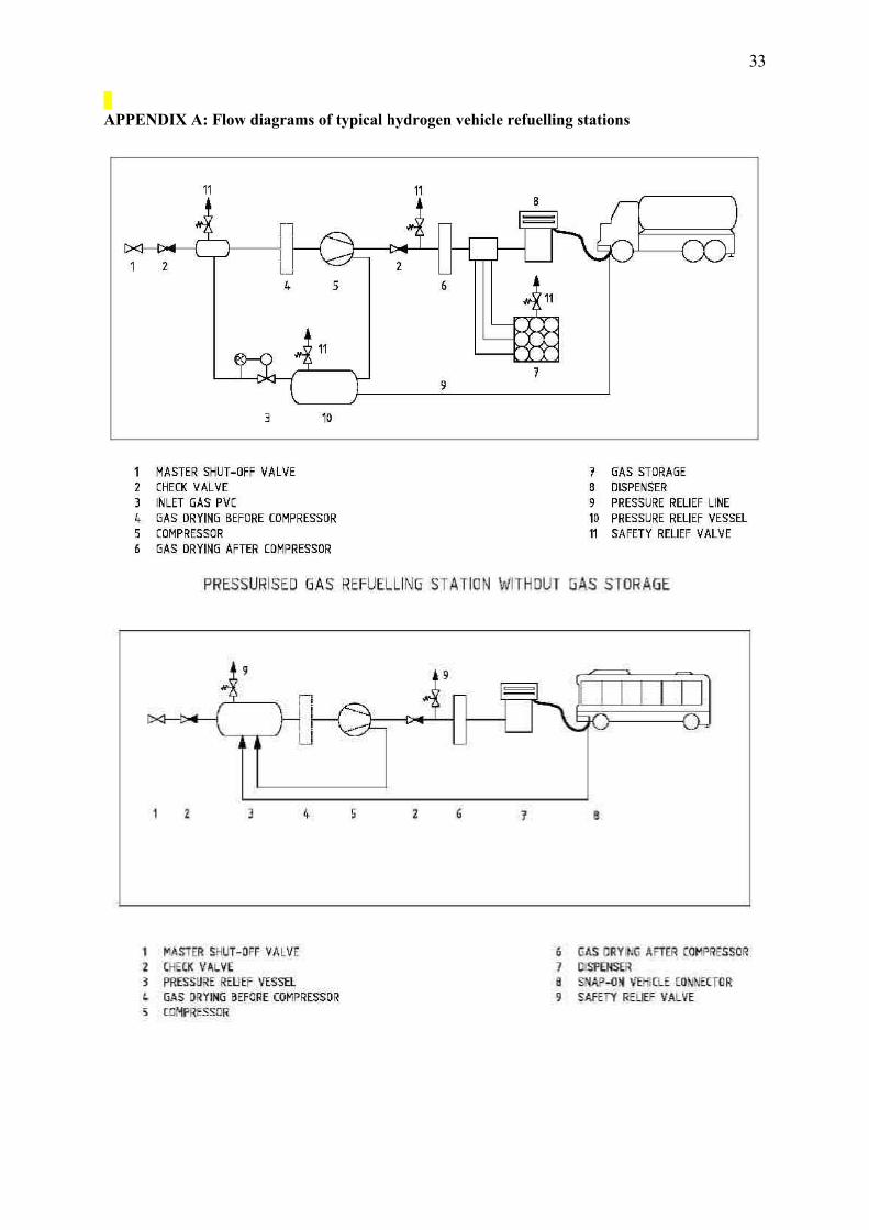
33
APPENDIX A: Flow diagrams of typical hydrogen vehicle refuelling stations
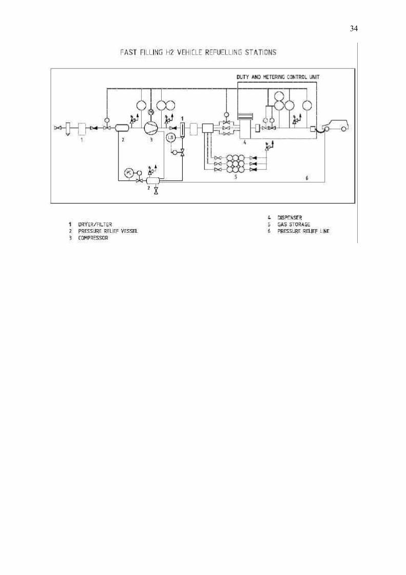
34
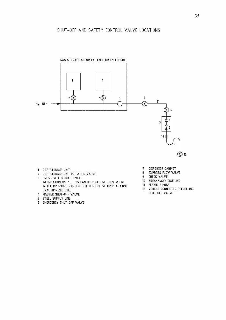
35
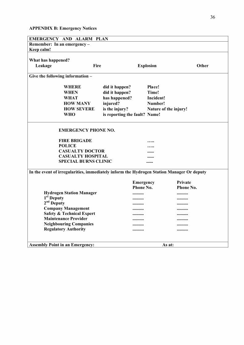
36
APPENDIX B: Emergency Notices
EMERGENCY AND ALARM PLANRemember: In an emergency –Keep calm!
What has happened?� Leakage � Fire � Explosion � Other
Give the following information –
� WHERE did it happen? Place!� WHEN did it happen? Time!� WHAT has happened? Incident!� HOW MANY injured? Number!� HOW SEVERE is the injury? Nature of the injury!� WHO is reporting the fault? Name!
EMERGENCY PHONE NO.
FIRE BRIGADE …..POLICE …..CASUALTY DOCTOR ......CASUALTY HOSPITAL ......SPECIAL BURNS CLINIC ......
In the event of irregularities, immediately inform the Hydrogen Station Manager Or deputy
Emergency PrivatePhone No. Phone No.
Hydrogen Station Manager .......... ..........1st Deputy .......... ..........2nd Deputy .......... ..........Company Management .......... ..........Safety & Technical Expert .......... ..........Maintenance Provider .......... ..........Neighbouring Companies .......... ..........Regulatory Authority .......... ..........
Assembly Point in an Emergency: As at:
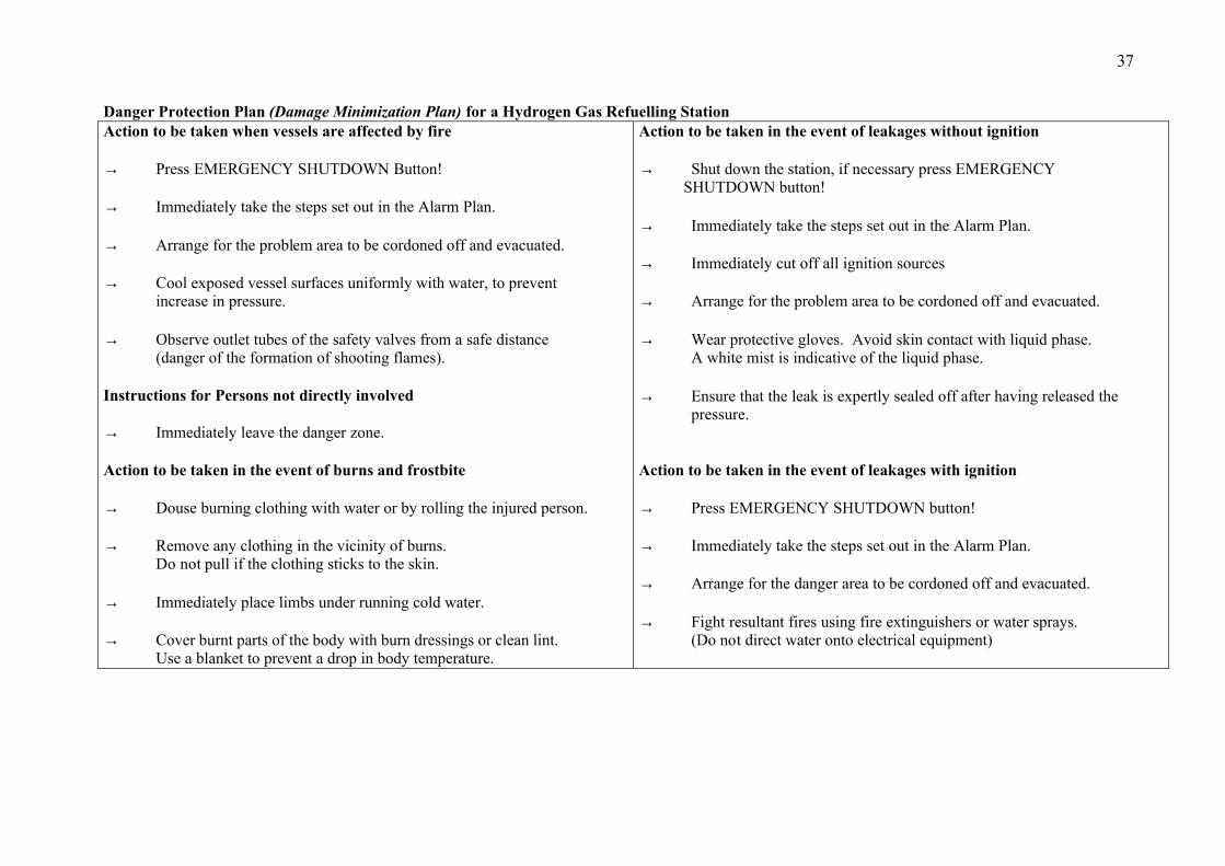
37
Danger Protection Plan (Damage Minimization Plan) for a Hydrogen Gas Refuelling StationAction to be taken when vessels are affected by fire
→ Press EMERGENCY SHUTDOWN Button!
→ Immediately take the steps set out in the Alarm Plan.
→ Arrange for the problem area to be cordoned off and evacuated.
→ Cool exposed vessel surfaces uniformly with water, to preventincrease in pressure.
→ Observe outlet tubes of the safety valves from a safe distance(danger of the formation of shooting flames).
Instructions for Persons not directly involved
→ Immediately leave the danger zone.
Action to be taken in the event of burns and frostbite
→ Douse burning clothing with water or by rolling the injured person.
→ Remove any clothing in the vicinity of burns.Do not pull if the clothing sticks to the skin.
→ Immediately place limbs under running cold water.
→ Cover burnt parts of the body with burn dressings or clean lint.Use a blanket to prevent a drop in body temperature.
Action to be taken in the event of leakages without ignition
→ Shut down the station, if necessary press EMERGENCY SHUTDOWN button!
→ Immediately take the steps set out in the Alarm Plan.
→ Immediately cut off all ignition sources
→ Arrange for the problem area to be cordoned off and evacuated.
→ Wear protective gloves. Avoid skin contact with liquid phase.A white mist is indicative of the liquid phase.
→ Ensure that the leak is expertly sealed off after having released thepressure.
Action to be taken in the event of leakages with ignition
→ Press EMERGENCY SHUTDOWN button!
→ Immediately take the steps set out in the Alarm Plan.
→ Arrange for the danger area to be cordoned off and evacuated.
→ Fight resultant fires using fire extinguishers or water sprays.(Do not direct water onto electrical equipment)
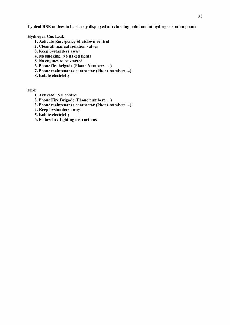
38
Typical HSE notices to be clearly displayed at refuelling point and at hydrogen station plant:
Hydrogen Gas Leak:1. Activate Emergency Shutdown control2. Close all manual isolation valves3. Keep bystanders away4. No smoking. No naked lights5. No engines to be started6. Phone fire brigade (Phone Number: ….)7. Phone maintenance contractor (Phone number: ...)8. Isolate electricity
Fire:1. Activate ESD control2. Phone Fire Brigade (Phone number: …)3. Phone maintenance contractor (Phone number: ...)4. Keep bystanders away5. Isolate electricity6. Follow fire-fighting instructions
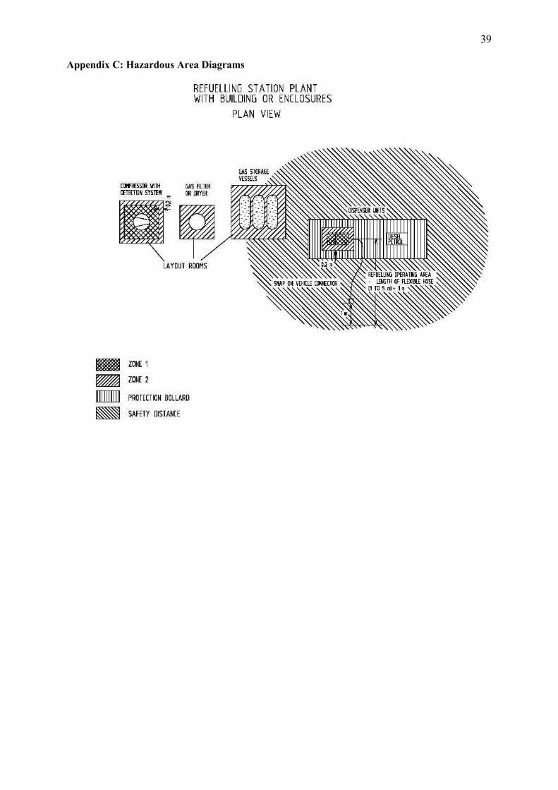
39
Appendix C: Hazardous Area Diagrams
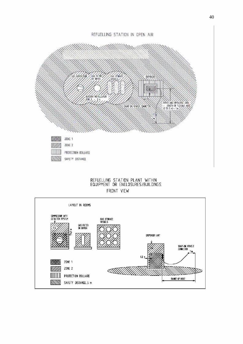
40
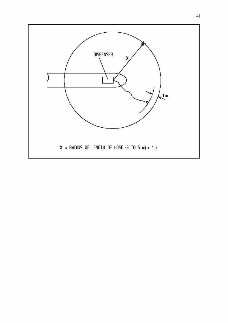
41
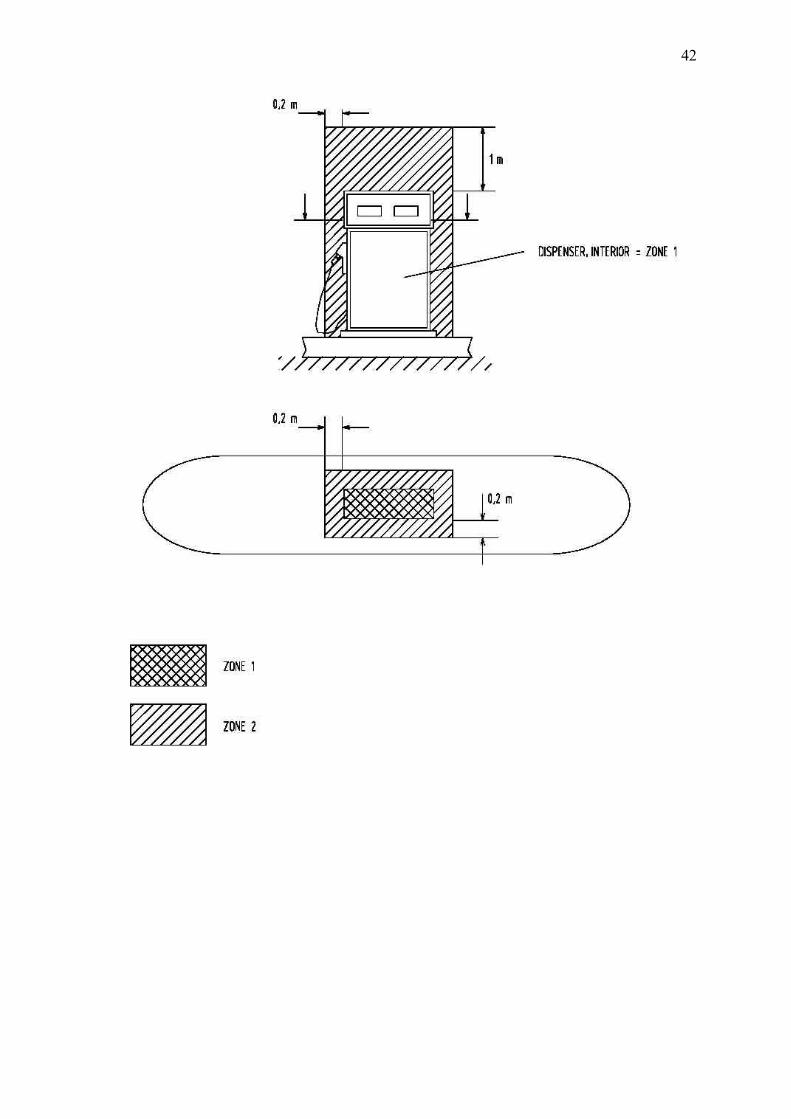
42