Embed Size (px)
Citation preview
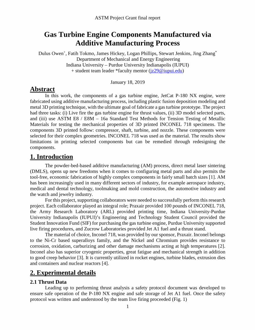
ASTM Project Grant final report
Gas Turbine Engine Components Manufactured via Additive Manufacturing Process
Dulus Owen+, Fatih Tokmo, James Hickey, Logan Phillips, Stewart Jenkins, Jing Zhang*
Department of Mechanical and Energy Engineering Indiana University – Purdue University Indianapolis (IUPUI)
+ student team leader *faculty mentor ([email protected])
January 18, 2019 Abstract
In this work, the components of a gas turbine engine, JetCat P-180 NX engine, were fabricated using additive manufacturing process, including plastic fusion deposition modeling and metal 3D printing technique, with the ultimate goal of fabricate a gas turbine prototype. The project had three tasks: (i) Live fire the gas turbine engine for thrust values, (ii) 3D model selected parts, and (iii) use ASTM E8 / E8M – 16a Standard Test Methods for Tension Testing of Metallic Materials for testing the mechanical properties of 3D printed INCONEL 718 specimens. The components 3D printed follow: compressor, shaft, turbine, and nozzle. These components were selected for their complex geometries. INCONEL 718 was used as the material. The results show limitations in printing selected components but can be remedied through redesigning the components.
1. Introduction
The powder-bed-based additive manufacturing (AM) process, direct metal laser sintering (DMLS), opens up new freedoms when it comes to configuring metal parts and also permits the tool-free, economic fabrication of highly complex components in fairly small batch sizes [1]. AM has been increasingly used in many different sectors of industry, for example aerospace industry, medical and dental technology, toolmaking and mold construction, the automotive industry and the watch and jewelry industry.
For this project, supporting collaborators were needed to successfully perform this research project. Each collaborator played an integral role; Praxair provided 100 pounds of INCONEL 718, the Army Research Laboratory (ARL) provided printing time, Indiana University-Purdue University Indianapolis (IUPUI)’s Engineering and Technology Student Council provided the Student Innovation Fund (SIF) for purchasing the gas turbine engine, Purdue University supported live firing procedures, and Zucrow Laboratories provided Jet A1 fuel and a thrust stand.
The material of choice, Inconel 718, was provided by our sponsor, Praxair. Inconel belongs to the Ni-Cr based superalloys family, and the Nickel and Chromium provides resistance to corrosion, oxidation, carburizing and other damage mechanisms acting at high temperatures [2]. Inconel also has superior cryogenic properties, great fatigue and mechanical strength in addition to good creep behavior [3]. It is currently utilized in rocket engines, turbine blades, extrusion dies and containers and nuclear reactors [4].
2. Experimental details
2.1 Thrust Data Leading up to performing thrust analysis a safety protocol document was developed to
ensure safe operation of the P-180 NX engine and safe storage of Jet A1 fuel. Once the safety protocol was written and understood by the team live firing proceeded (Fig. 1)
1
ASTM Project Grant final report
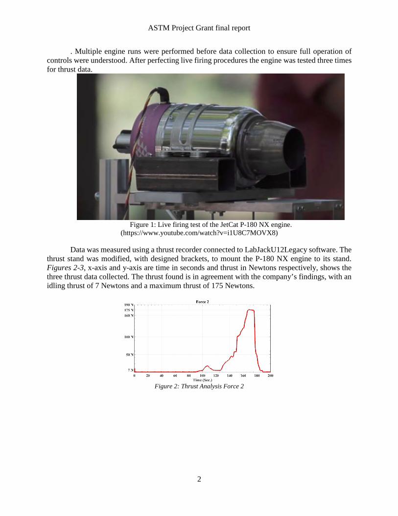
. Multiple engine runs were performed before data collection to ensure full operation of controls were understood. After perfecting live firing procedures the engine was tested three times for thrust data.
Figure 1: Live firing test of the JetCat P-180 NX engine.
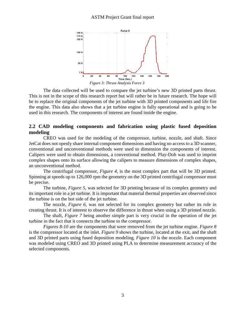
(https://www.youtube.com/watch?v=i1U8C7MOVX8) Data was measured using a thrust recorder connected to LabJackU12Legacy software. The
thrust stand was modified, with designed brackets, to mount the P-180 NX engine to its stand. Figures 2-3, x-axis and y-axis are time in seconds and thrust in Newtons respectively, shows the three thrust data collected. The thrust found is in agreement with the company’s findings, with an idling thrust of 7 Newtons and a maximum thrust of 175 Newtons.
Figure 2: Thrust Analysis Force 2
2
ASTM Project Grant final report
Figure 3: Thrust Analysis Force 3
The data collected will be used to compare the jet turbine’s new 3D printed parts thrust. This is not in the scope of this research report but will rather be in future research. The hope will be to replace the original components of the jet turbine with 3D printed components and life fire the engine. This data also shows that a jet turbine engine is fully operational and is going to be used in this research. The components of interest are found inside the engine.
2.2 CAD modeling components and fabrication using plastic fused deposition modeling
CREO was used for the modeling of the compressor, turbine, nozzle, and shaft. Since JetCat does not openly share internal component dimensions and having no access to a 3D scanner, conventional and unconventional methods were used to dimension the components of interest. Calipers were used to obtain dimensions, a conventional method. Play-Doh was used to imprint complex shapes onto its surface allowing the calipers to measure dimensions of complex shapes, an unconventional method.
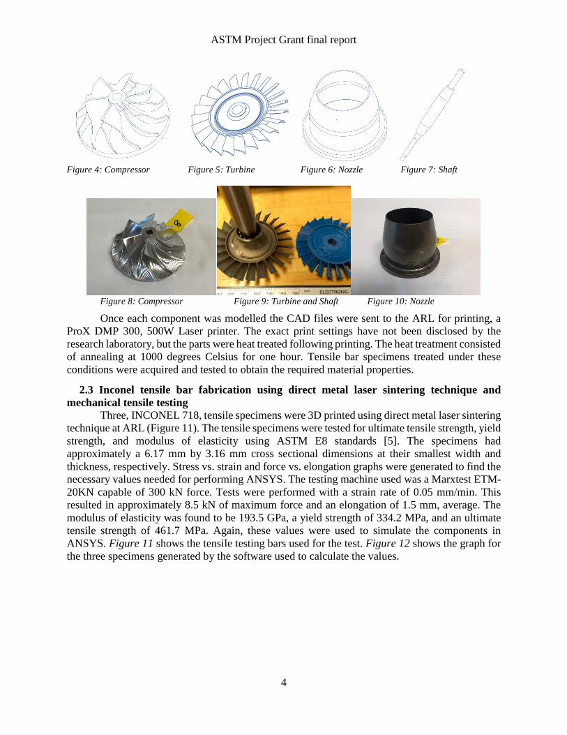
The centrifugal compressor, Figure 4, is the most complex part that will be 3D printed. Spinning at speeds up to 126,000 rpm the geometry on the 3D printed centrifugal compressor must be precise.
The turbine, Figure 5, was selected for 3D printing because of its complex geometry and its important role in a jet turbine. It is important that material thermal properties are observed since the turbine is on the hot side of the jet turbine.
The nozzle, Figure 6, was not selected for its complex geometry but rather its role in creating thrust. It is of interest to observe the difference in thrust when using a 3D printed nozzle.
The shaft, Figure 7 being another simple part is very crucial in the operation of the jet turbine in the fact that it connects the turbine to the compressor.
Figures 8-10 are the components that were removed from the jet turbine engine. Figure 8 is the compressor located at the inlet. Figure 9 shows the turbine, located at the exit, and the shaft and 3D printed parts using fused deposition modeling. Figure 10 is the nozzle. Each component was modeled using CREO and 3D printed using PLA to determine measurement accuracy of the selected components.
3
ASTM Project Grant final report
Figure 4: Compressor Figure 5: Turbine Figure 6: Nozzle Figure 7: Shaft
Figure 8: Compressor Figure 9: Turbine and Shaft Figure 10: Nozzle
Once each component was modelled the CAD files were sent to the ARL for printing, a ProX DMP 300, 500W Laser printer. The exact print settings have not been disclosed by the research laboratory, but the parts were heat treated following printing. The heat treatment consisted of annealing at 1000 degrees Celsius for one hour. Tensile bar specimens treated under these conditions were acquired and tested to obtain the required material properties.
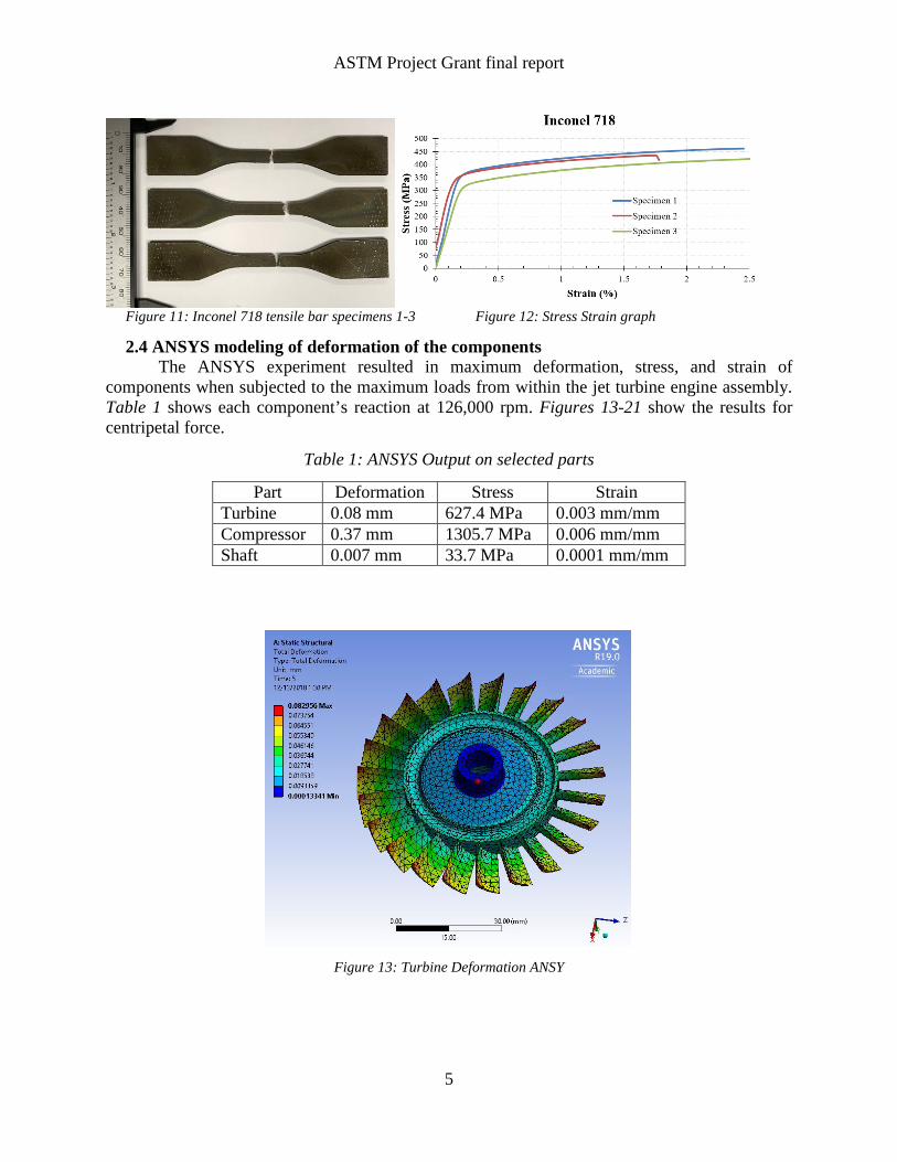
2.3 Inconel tensile bar fabrication using direct metal laser sintering technique and mechanical tensile testing Three, INCONEL 718, tensile specimens were 3D printed using direct metal laser sintering technique at ARL (Figure 11). The tensile specimens were tested for ultimate tensile strength, yield strength, and modulus of elasticity using ASTM E8 standards [5]. The specimens had approximately a 6.17 mm by 3.16 mm cross sectional dimensions at their smallest width and thickness, respectively. Stress vs. strain and force vs. elongation graphs were generated to find the necessary values needed for performing ANSYS. The testing machine used was a Marxtest ETM-20KN capable of 300 kN force. Tests were performed with a strain rate of 0.05 mm/min. This resulted in approximately 8.5 kN of maximum force and an elongation of 1.5 mm, average. The modulus of elasticity was found to be 193.5 GPa, a yield strength of 334.2 MPa, and an ultimate tensile strength of 461.7 MPa. Again, these values were used to simulate the components in ANSYS. Figure 11 shows the tensile testing bars used for the test. Figure 12 shows the graph for the three specimens generated by the software used to calculate the values.
4
ASTM Project Grant final report
Figure 11: Inconel 718 tensile bar specimens 1-3 Figure 12: Stress Strain graph
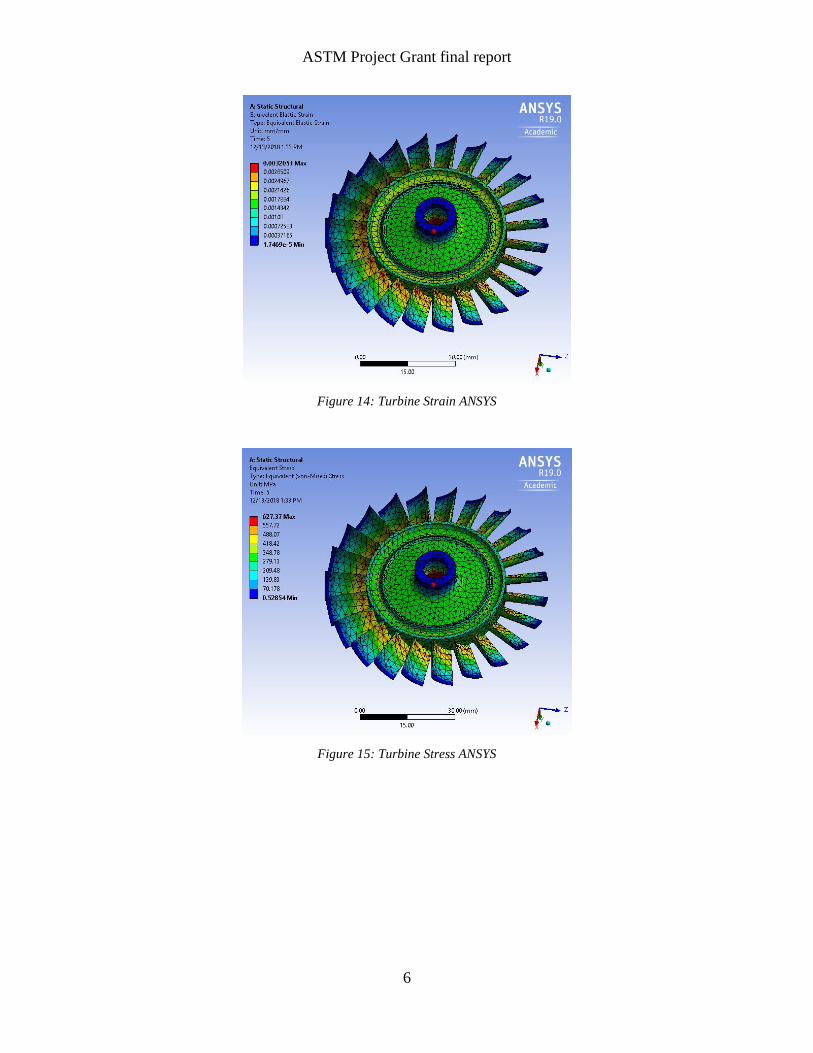
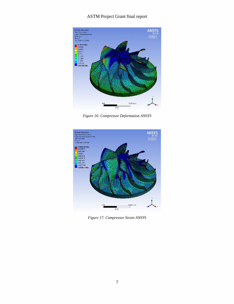
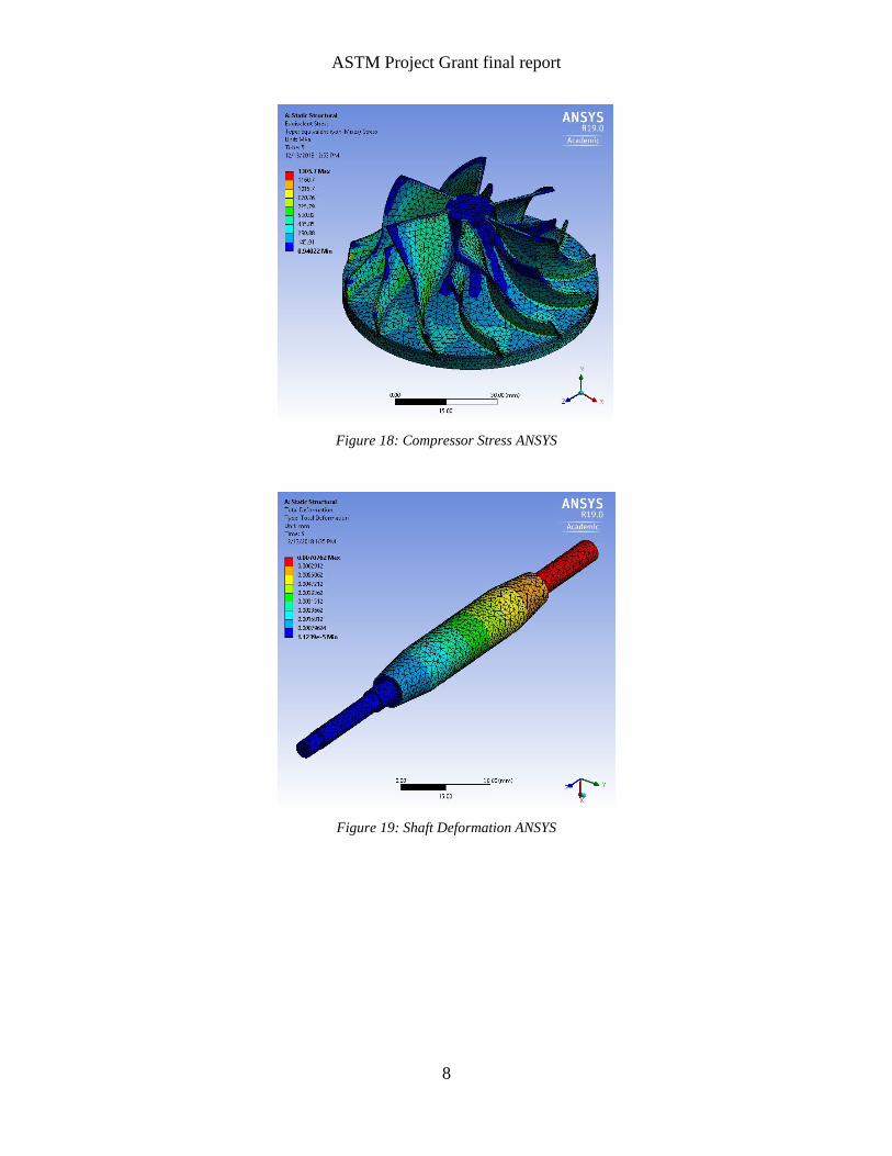
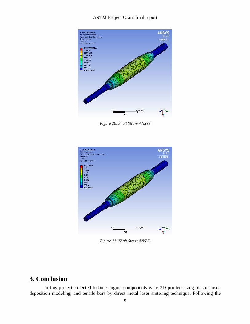
2.4 ANSYS modeling of deformation of the components The ANSYS experiment resulted in maximum deformation, stress, and strain of components when subjected to the maximum loads from within the jet turbine engine assembly. Table 1 shows each component’s reaction at 126,000 rpm. Figures 13-21 show the results for centripetal force.
Table 1: ANSYS Output on selected parts
Part Deformation Stress Strain Turbine 0.08 mm 627.4 MPa 0.003 mm/mm Compressor 0.37 mm 1305.7 MPa 0.006 mm/mm Shaft 0.007 mm 33.7 MPa 0.0001 mm/mm
Figure 13: Turbine Deformation ANSY
5
ASTM Project Grant final report
Figure 14: Turbine Strain ANSYS
Figure 15: Turbine Stress ANSYS
6
ASTM Project Grant final report
Figure 16: Compressor Deformation ANSYS
Figure 17: Compressor Strain ANSYS
7
ASTM Project Grant final report
Figure 18: Compressor Stress ANSYS
Figure 19: Shaft Deformation ANSYS
8
ASTM Project Grant final report
Figure 20: Shaft Strain ANSYS
Figure 21: Shaft Stress ANSYS
3. Conclusion
In this project, selected turbine engine components were 3D printed using plastic fused deposition modeling, and tensile bars by direct metal laser sintering technique. Following the
9
ASTM Project Grant final report
ASTM E8 standard, satisfactory mechanical properties are achieved using metal 3D printing. Additionally, the deformation of the selected components in the simulated loading conditions were calculated using ANSYS. The project demonstrates the feasibility of using 3D printing to fabricate components for gas turbine.
4. Recommendations of future work
Though tensile testing provided useful material properties, it is recommended that more tests be performed, including several more tensile tests, compression tests, creep tests, and axial fatigue tests. It is recommended to use ASTM standards and follow the suggested report procedure of each standard. Exact dimensions of the original parts may be desirable to make a more sophisticated performance comparison between data from the engine with original parts to the engine with 3D printed parts. It is recommended to contact a company who specializes in 3D scanning to provide the service.
References
[1] Gu, Dongdon. Laser additive manufacturing of high-performance materials. Springer, 2015. [2] Ganesan, Prabhu and C. Rentería. “Veratile Corrosion Resistance of INCONEL alloy 625 in
Various Aqueous and Chemical Processing Environments.” (1998). [3] Special Metals Data Sheet. “INCONEL® alloy 718.” Publication Number SMC-045. Special
Metals Corporation (2007). [4] Thomas, A., et al. “High temperature deformation of Inconel 718.” Journal of materials
processing technology 177. 1-3 (2006): 469-472. [5] ASTM E8 / E8M-16a, Standard Test Methods for Tension Testing of Metallic Materials,
ASTM International, West Conshohocken, PA, 2016, www.astm.org
Acknowledgement
The research project performed by IUPUI, led by Dulus Owen, was supported and funded by ASTM International University Students Senior Design Project Grant. This capstone project was organized by Dr. John Stang. The team leader and mentor would also like to thank the U.S. Army Research Laboratory (Dr. Brandon McWilliams), Praxair Surface Technologies (TruFormTM Ambition Grant), IUPUI Student Innovation Fund (donor Tom Ward), and Zucrow Laboratories for all their input, funding, and supplies.
10