Embed Size (px)
Citation preview

0
A GLOBAL
LEADER
IN METAL AM
Optimized Turbine BracketOptimizing, Testing and Fabricating a Low Pressure
Turbine Cooling Bracket by Additive Manufacturing
0

1
Project Overview
Prove the ability to additively manufacture:
Exact replacement of an existing aerospace bracket that meets or exceeds existing brackets mechanical and operational properties.
Optimized design of the same existing aerospace bracket that meets or exceeds existing bracket’s mechanical and operational properties while decreasing the overall weight of the bracket.
2017 © Sintavia, LLC

2
What is solidThinking Inspire?
solidThinking Inspire enables design engineers, product
designers, and architects to create and investigate
structurally efficient concepts quickly and easily.
Inspire helps its users to design products:
Faster LighterSmarter
2017 © Sintavia, LLC

3
Inspire Design Process
Traditional Design Process
Validation & Prototyping
Documentation
Product
Definition
Inspire Design Process
ProductionDetailed Design
Inspire
Develop
Concept
Detailed Design
Production
Validation & Prototyping
Documentation
Product
Definition
Start with the solution and shorten time to market
2017 © Sintavia, LLC

4
What is solidThinking Evolve?
Evolve is a Hybrid Modeling and Rendering
environment that enables designers to evaluate,
research and visualize various designs faster than ever
before.
Preliminary design.
4
Organic design
Flexible workflow
Surface Modeling
Mechanical design
Parametric
Solid Modeling
Organic design
Simple workflow
Polygonal Modeling
2017 © Sintavia, LLC 6/29/2017

5
Why?
Metal AM and generative design tools like solidThinking® have the ability to aid Maintenance, Repair, and Overhaul (“MRO”) organizations within the aviation industry by:
Streamlined and improved fabrication techniques from AM
Make and buy decisions used in procurement
Internal fabrication
Virtual inventory requirement advantages
Replacement ease of obsolete part
Performance improvements in weight, strength and fatigue life
2017 © Sintavia, LLC

6
OEM Bracket
OEM Bracket Clearance control cooling manifold bracket on low pressure turbine assembly with
replaceable slotted entry bearings.
12 Brackets per engine mounted externally
Cast Inconel 718 confirmed by EDS and OES.
2017 © Sintavia, LLC

7
OEM Bracket
2017 © Sintavia, LLC
8
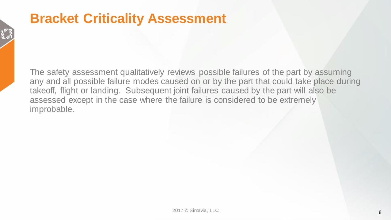
Bracket Criticality Assessment
The safety assessment qualitatively reviews possible failures of the part by assuming any and all possible failure modes caused on or by the part that could take place during takeoff, flight or landing. Subsequent joint failures caused by the part will also be assessed except in the case where the failure is considered to be extremely improbable.
2017 © Sintavia, LLC

9
Bracket Severity Classification and Probability Level Description
Severity
ClassSeverity Description
Minor
An engine failure in which the only consequence is partial or complete
loss of thrust or power (and associated engine services) from the engine
will be regarded as a minor engine effect.
MajorAn effect whose severity falls between a minor and hazardous will be
regarded as a major engine effect.
Hazardous
The following effects will be regarded as hazardous engine effects:
1. Non-containment of high energy debris.
2. Concentration of toxic products in the engine bleed air
sufficient to incapacitate crew or passengers.
3. Significant thrust in opposite direction to that of pilot.
4. Uncontrolled fire.
5. Failure of the engine mount system leading to the engine
separation.
6. Release of the propeller by the engine, if applicable.
7. Complete inability to shut the engine down.
Probability
ClassProbability Description
Extremely
Improbable
Conditions are so unlikely, that they are not anticipated to occur during
the entire operational life of all engines of one type.
Improbable
Conditions that are not anticipated to occur during the entire operational
life of a single random engine. However, they may occur occasionally
during the entire operational life of all engines of one type.
ProbableConditions are those anticipated to occur one or more times during the
entire operational life of each engine.
2017 © Sintavia, LLC

10
Bracket Failure Mode and Cause and EffectFailure Severity Probability Cause Effect
General Wear Minor ProbableGeneral wear and degradation
of slotted entry bearing.
Scoring, pitting, scratching, corrosion.
Possible seizing of bearing.
Bracket Fracture Minor Extremely ImprobableExcessive load or operation
beyond fatigue lifeIncreased vibration in cooling system.
Bracket Fracture (A) New Bearing (B) Worn Bearing
A B

11
Optimization: Overview
A. Bluelight Scanning
B. Solid Modeling/Scan Comparison
C. Inspire Optimization
D. Evolve PolyNurbing
E. Finalizing Designs
2017 © Sintavia, LLC
12
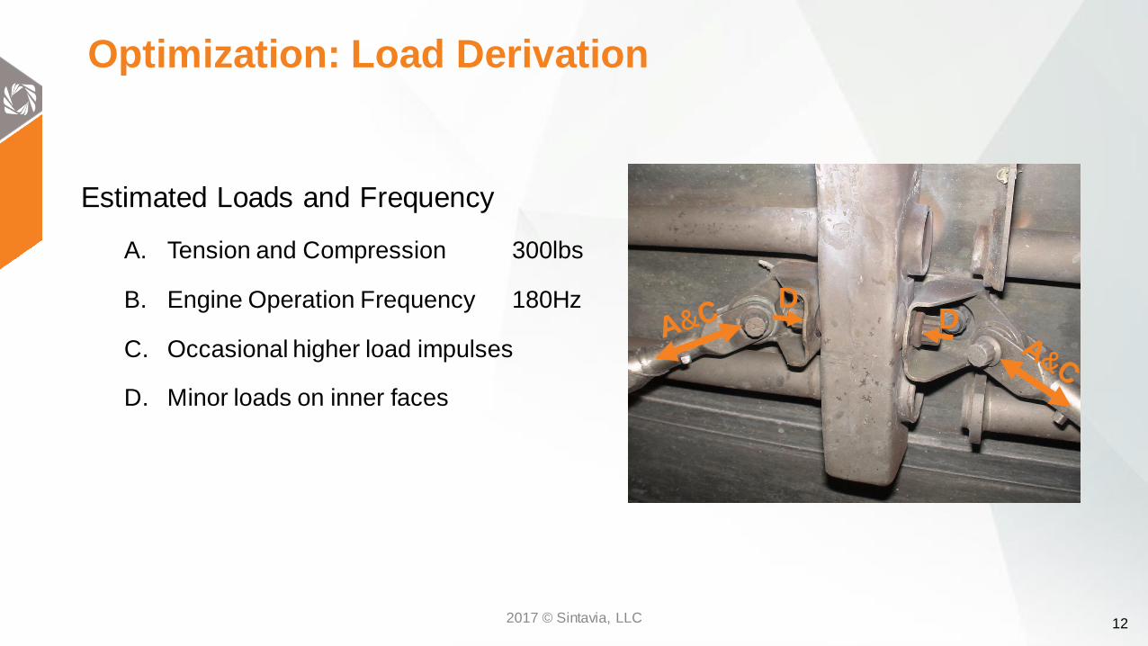
Estimated Loads and Frequency
A. Tension and Compression 300lbs
B. Engine Operation Frequency 180Hz
C. Occasional higher load impulses
D. Minor loads on inner faces
Optimization: Load Derivation
DD
2017 © Sintavia, LLC
13
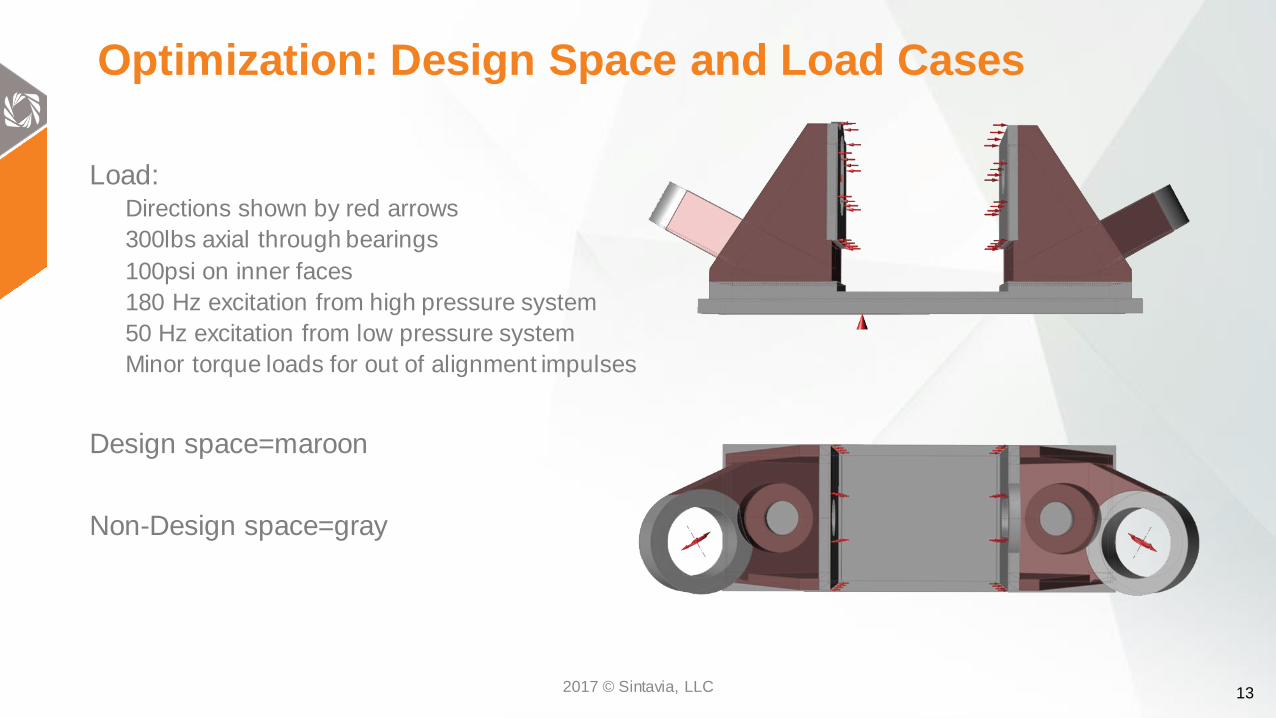
Optimization: Design Space and Load Cases
Load: Directions shown by red arrows
300lbs axial through bearings
100psi on inner faces
180 Hz excitation from high pressure system
50 Hz excitation from low pressure system
Minor torque loads for out of alignment impulses
Design space=maroon
Non-Design space=gray
2017 © Sintavia, LLC

14
Optimization: Inspire
OEM CADOpt 1 Opt 2 Opt 3
Opt 4Opt 5Opt 6Opt 7
2017 © Sintavia, LLC
15
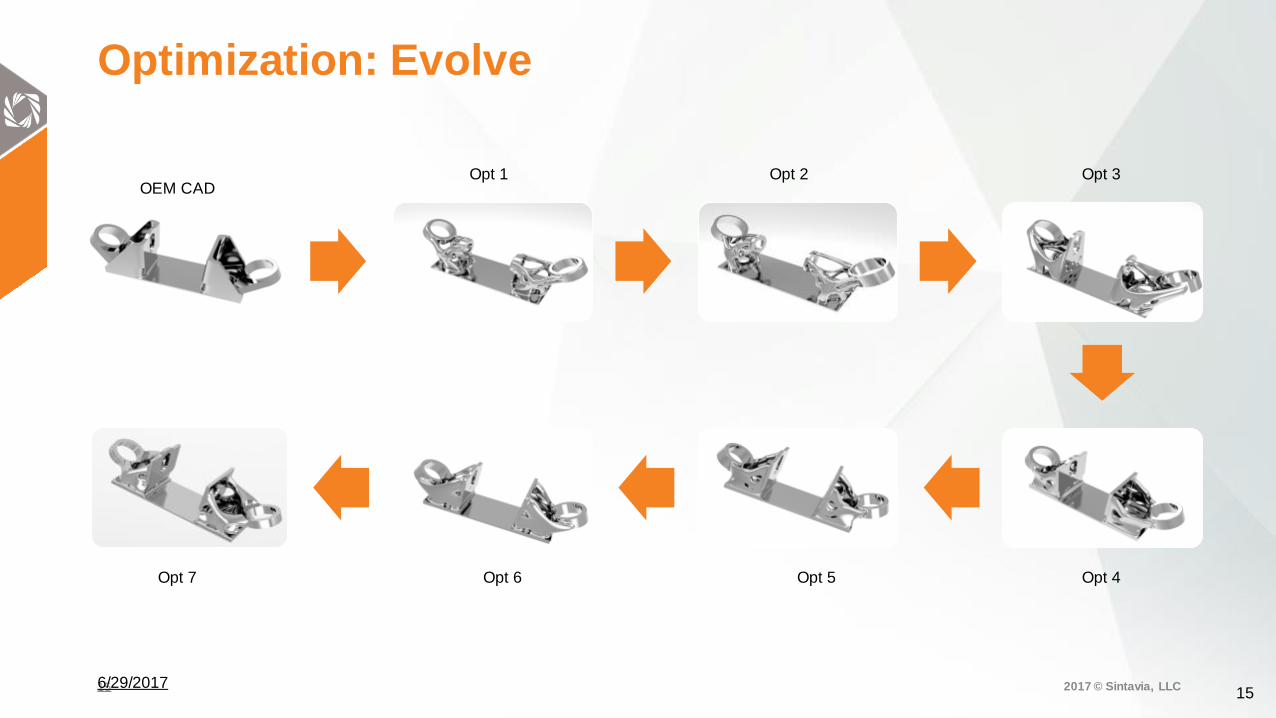
Optimization: Evolve
15
OEM CADOpt 1 Opt 2 Opt 3
Opt 4Opt 5Opt 6Opt 7
2017 © Sintavia, LLC 6/29/2017
16
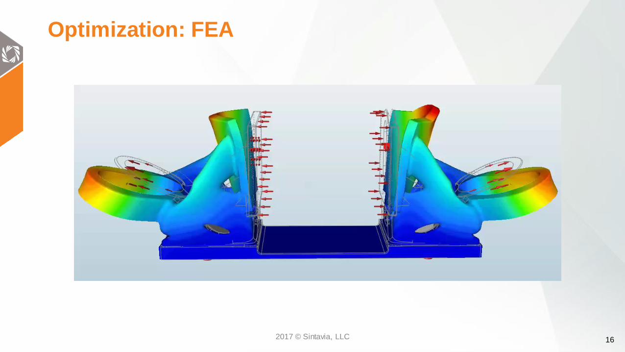
Optimization: FEA
2017 © Sintavia, LLC

17
Optimization: FEA Comparison
2017 © Sintavia, LLC
18
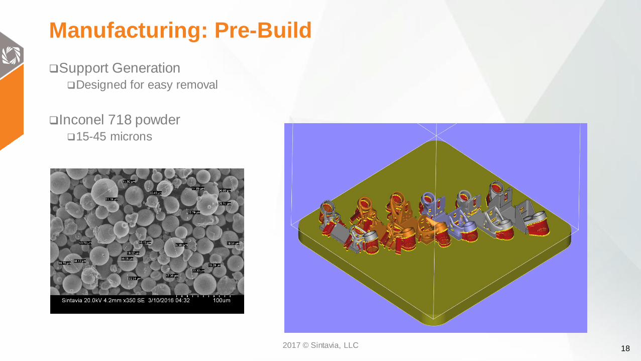
Manufacturing: Pre-Build
Support GenerationDesigned for easy removal
Inconel 718 powder15-45 microns
2017 © Sintavia, LLC

19
Manufacturing: SLM 280 Twin Laser
2017 © Sintavia, LLC
20
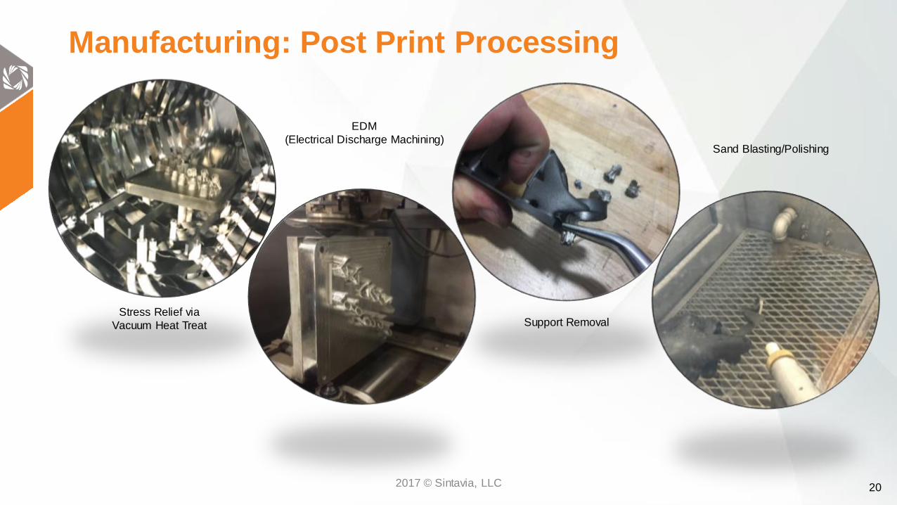
Manufacturing: Post Print Processing
Stress Relief via
Vacuum Heat Treat
EDM
(Electrical Discharge Machining)
Support Removal
Sand Blasting/Polishing
2017 © Sintavia, LLC

21
Manufacturing: Hot Isostatic Pressing
Treatment14.5 KSI
2155°F
2 hours
2017 © Sintavia, LLC
22
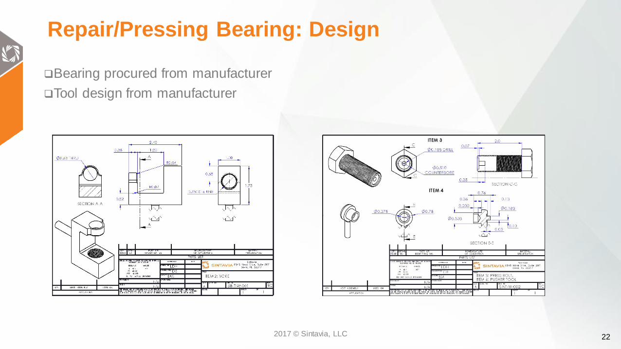
Repair/Pressing Bearing: Design
Bearing procured from manufacturer
Tool design from manufacturer
2017 © Sintavia, LLC

23
Repair/Pressing Bearing: Manufacturing
CAD In-UseChasing Threads
Additively manufacturing the bearing press assembly reduces the lead time on bearing repairs
Printing
2017 © Sintavia, LLC

24
Repair/Pressing Bearing: Brackets
2017 © Sintavia, LLC

25
Testing: Apparatus Design
Designed to match operational load directions
Allows for three different load angles to be tested
Manufactured via AM and HIP
2017 © Sintavia, LLC
26
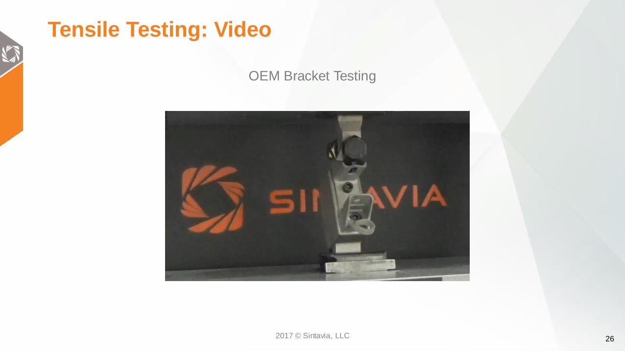
Tensile Testing: Video
OEM Bracket Testing
2017 © Sintavia, LLC

27
Tensile Testing: UTS Results
OEM Bracket
Stress vs. Strain
OEM Bracket
Load vs. Extension
*Stress determined via smallest cross sectional area at failure point indicated by FEA**Stain determined via crosshead movement
Maximum Load Maximum Stress
5160 lbf 134.5 ksi
2017 © Sintavia, LLC

28
Fatigue Testing: Parameters
• Tested in tension at • 20 Hz
• Fmin=1000lbs (≈20% UTS)
• Fmax=2000lbs (≈40% UTS)
• Fmean=1500lbs (≈30% UTS)
2017 © Sintavia, LLC

29
Fatigue Testing: Results
0
20000
40000
60000
80000
100000
120000
140000
0.000
0.050
0.100
0.150
0.200
0.250
OEM OEM Printed Opt 5 Opt 6 Opt 7 OEM Printed(HIP)
Opt 5 (HIP) Opt 6 (HIP)
Cycle
s (
Count)
Mass (
lbm
)
Bracket Comparison
Mass Cycles (Fm=1500 lbf)(Fa=500lbf)
Bracket
CAD
Predicted
Mass (lbm)
Mass
(lbm)
Cycles
(Fm=1500 lbf)
(Fa=500lbf)
OEM 0.21 0.228 42476
As B
uilt
OEM Printed (0.21) 0.206 44400
Opt 5 0.19 0.186 30620
Opt 6 0.20 0.200 77326
Opt 7 0.19 0.188 46905
HIP
OEM Printed (0.21) 0.188 121063
Opt 5 (0.19) 0.172 64950
Opt 6 (0.20) 0.195 95773
2017 © Sintavia, LLC

30
Fatigue Testing: Effect of HIP
0
20000
40000
60000
80000
100000
120000
140000
OEM Printed Opt 5 Opt 6
Cycle
s
Effect of HIP
Non-HIP HIP
2017 © Sintavia, LLC

31
As Printed Inco 718 Metallography
2017 © Sintavia, LLC

32
Metallurgy: Grain Structure
OEM Casting-Dendritic Columnar Structure AM HIPed-Laves Free
2017 © Sintavia, LLC

33
Metallurgy: Porosity
OEM Casting-200X AM Hipped-200X
2017 © Sintavia, LLC
34
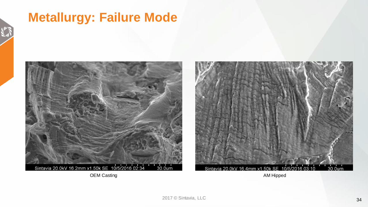
Metallurgy: Failure Mode
OEM Casting AM Hipped
2017 © Sintavia, LLC
35
Conclusions: Direct Replacement
Based on mechanical and metallurgical testing, AM brackets can become a suitable direct substitution for cast parts.
Mechanical testing shows:Equivalent cycles to failure of an as printed AM direct replacement of the cast OEM bracket
Results also showed a tripled fatigue life for a HIPed AM direct replacement
Metallurgical testing shows: Less porosity in an HIPed AM direct replacement than in the cast OEM bracket
Exploring refinement of hardness through solution or precipitation heat treatment.
2017 © Sintavia, LLC
36
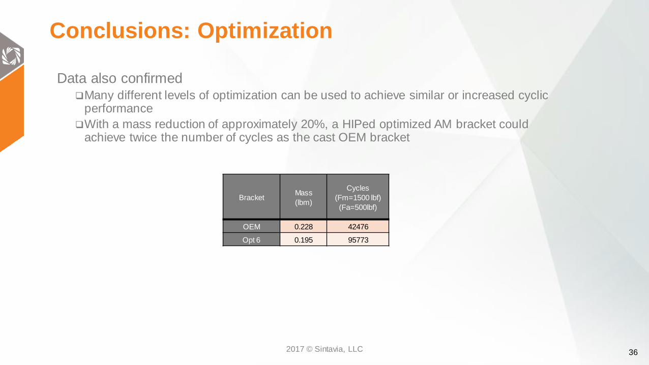
Conclusions: Optimization
Data also confirmedMany different levels of optimization can be used to achieve similar or increased cyclic
performance
With a mass reduction of approximately 20%, a HIPed optimized AM bracket could achieve twice the number of cycles as the cast OEM bracket
BracketMass
(lbm)
Cycles
(Fm=1500 lbf)
(Fa=500lbf)
OEM 0.228 42476
Opt 6 0.195 95773
2017 © Sintavia, LLC
37
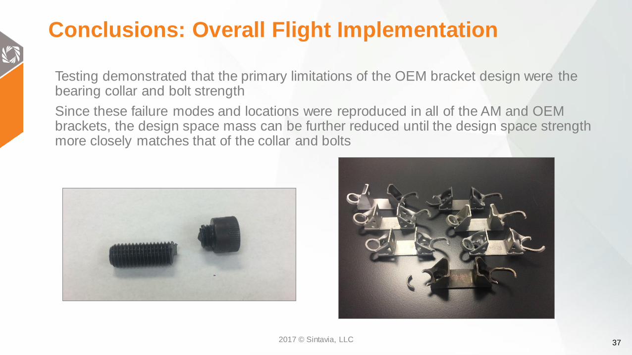
Conclusions: Overall Flight Implementation
Testing demonstrated that the primary limitations of the OEM bracket design were the bearing collar and bolt strength
Since these failure modes and locations were reproduced in all of the AM and OEM brackets, the design space mass can be further reduced until the design space strength more closely matches that of the collar and bolts
2017 © Sintavia, LLC
38
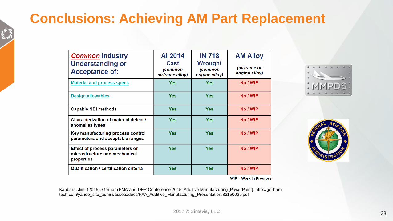
Conclusions: Achieving AM Part Replacement
Kabbara, Jim. (2015). Gorham PMA and DER Conference 2015: Additive Manufacturing [PowerPoint]. http://gorham-tech.com/yahoo_site_admin/assets/docs/FAA_Additive_Manufacturing_Presentation.83150029.pdf
2017 © Sintavia, LLC

39
Conclusions: Achieving AM Part Replacement
FAA acceptable material specifications for AM have not been developed at this time.
Each manufacturer will need to develop process specifications for their specific fabrication method.
Strength properties must be based on testing of materials meeting approved specifications to establish design values on a statistical basis.
Need to develop MMPDS procedures which would allow individual manufacturer to demonstrate that mechanical properties of parts being produced by AM in their facilities is “equivalent” to the properties of values published in MMPDS.
Fatigue and damage tolerance properties need to be discussed separately.Kabbara, Jim. (2015). Gorham PMA and DER Conference 2015: Additive Manufacturing [PowerPoint]. http://gorham-tech.com/yahoo_site_admin/assets/docs/FAA_Additive_Manufacturing_Presentation.83150029.pdf
2017 © Sintavia, LLC
40
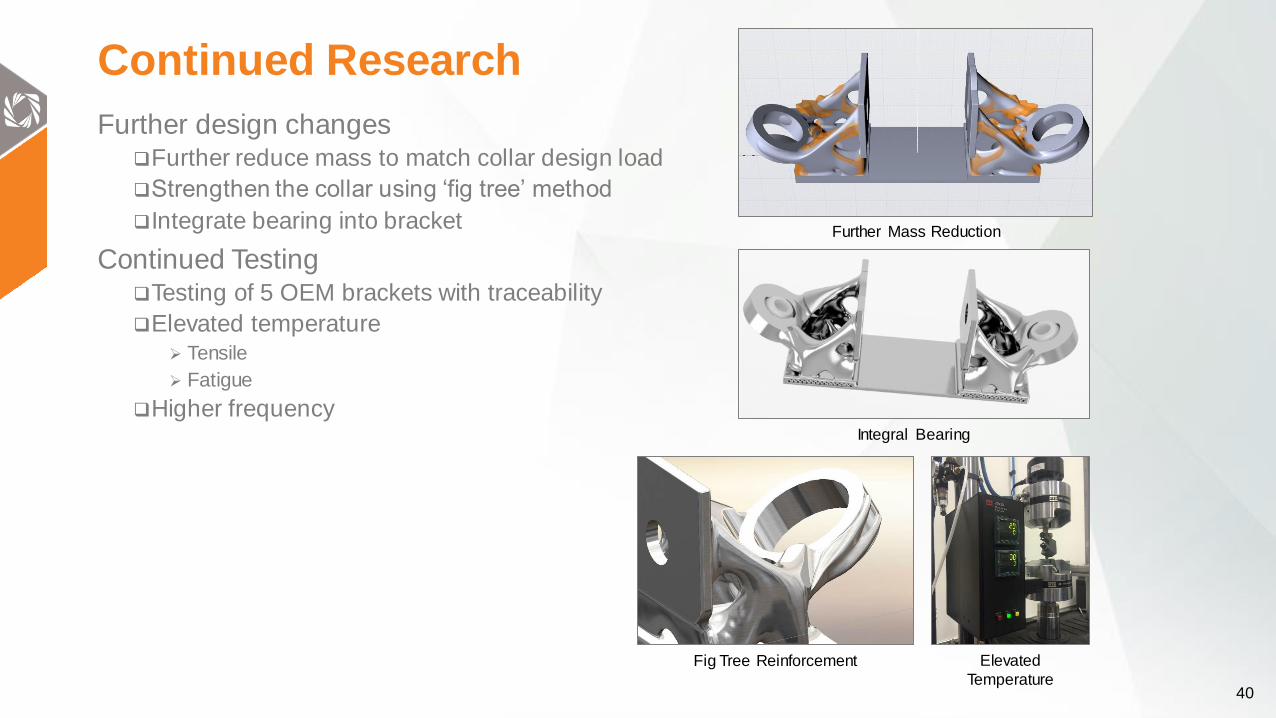
Continued Research
Further design changesFurther reduce mass to match collar design load
Strengthen the collar using ‘fig tree’ method
Integrate bearing into bracket
Continued TestingTesting of 5 OEM brackets with traceability
Elevated temperature Tensile
Fatigue
Higher frequencyIntegral Bearing
Further Mass Reduction
Fig Tree Reinforcement Elevated
Temperature