Embed Size (px)
Citation preview
Gas Processing JournalVVooll.. 55,, NNoo.. 11,, 22001177hhttttpp::////ggppjj..uuii..aacc..iirrDOI: 10.22108/GPJ.2017.100034.1000
___________________________________________
* Corresponding Author. Authors’ Email Address:1 M. Shariati Niasar ([email protected]), 2 Majid Amidpour ([email protected]), 3 Bahram Ghorbani ([email protected])3, Mohammad-Javad Rahimi ([email protected]), 4 Mehdi Mehrpooya ([email protected]),5
Mohammad-Hossein Hamedi([email protected])6
ISSN (Online): 2345-4172, ISSN (Print): 2322-3251 © 2017 University of Isfahan. All rights reserved
Superstructure of Cogeneration of Power, Heating, Cooling and Liquid Fuels Using Gasification of Feedstock with Primary Material of Coal for Employing in LNG Process Malek Shariati Niasar1*, Majid Amidpour1, Bahram Ghorbani2,3, Mohammad-Javad Rahimi3, Mehdi Mehrpooya4, Mohammad-Hossein Hamedi3
1Mechanical Engineering Faculty, Energy Systems Group, KNToosi University of Technology, Tehran, Iran 2 Faculty of Engineering Technology, Amol University of Special Modern Technologies, Amol, Iran 3 Mechanical Engineering Faculty, Energy Conversion Group, KNToosi University of Technology, Tehran, Iran 4 Renewable Energies and Environmental Department, Faculty of New Sciences and Technologies, University of Tehran, Tehran, Iran
Article HistoryReceived: 2016-11-02 Revised: 2017-06-07 Accepted: 2017-08-24
AbstractUsing absorption refrigeration cycles instead of vapor compression refrigeration cycles can drastically decrease energy consumption. In these systems, high level of energy consumption is reduced due to the partially elimination of vapor compression refrigeration systems. On the other hand, utilization of waste heat of the plant, which is a very good opportunity for energy saving, is possible. In the present paper, a novel mixed fluid cascade natural gas liquefaction process is investigated by exergy and exergoeconomic analysis methods. In this process, one of the vapor compression cycles is replaced by water-ammonia absorption refrigeration cycle. The simulation results show that the compressors of this plant are responsible for 43.2% of total exergy lost. Decision variables of the system are consists of mass flow ratio of the tower’s bottom product (bottom feed ratio), number of trays, and compressor’s pressure ratio. Choosing appropriate values for these variables will result in 12% increase in exergetic efficiency of the plant. Exergoeconomic factor of water coolers, heat exchanger no.1 and tower no.1 shows that these components respectively impose a sizable capital cost to the entire system and does not result to a reasonable capital recovery. In this paper an integrated structure of producing liquid fuels from coal using Fischer-Tropsch synthesis and some equipment such as gas and steam turbines as well as HRSG heat exchanger for recovering of heat and power has been developed. Gasification method because of high efficiency and exothermic nature from energy consumption point of view is employed for producing synthesis gas.
KeywordsCogeneration, Natural Gas Liquids (LNG), Gasification, Exergoeconomic
1. Introduction Liquefied natural gas (LNG) is natural gas in a liquid form that is clear, colorless, odorless, noncorrosive, and nontoxic, occupying only 1/600th of its normal volume in gaseous form. LNG is formed when natural gas is cooled by a refrigeration process to temperatures of
between 159 ºC and –162 ºC through a process known as liquefaction (Bahadori, 2014). Today, natural gas, often supplied as LNG, is particularly well-suited for use in the combined cycle technology used in independent power generation projects (IPPs). LNG has established a niche for itself by matching remote gas supplies to markets that lacks indigenous gas
2 Gas Processing Journal, Vol. 5, No. 1, 2017
GGPPJJ
reserves (Avidan, Gardner, Nelson, Borrelli, & Rethore, 1997). High amount of energy is needed to liquefy and sub-cool the natural gas to temperatures around -160 ºC. In general, compressors of the refrigeration cycles are the biggest energy consumer of the liquefaction process. In fact, the electrical power required for compression refrigeration cycles (CRCs) is the highest energy sink of the plant. In order to define the efficiency of the natural gas liquefaction (NGL) process, an index named specific power consumption (SPC) is introduced. This index expresses the amount of the required power (kWh) to produce 1 kg of LNG. According to reference (Waldmann, 2008) SPC varies from 0.3 to 0.8 (kWh/Kg LNG). Several researches have been conducted to improve efficiency of NGL processes. Mixed fluid cascade (MFC) process is a technology, which has been developed to reduce the power required for LNG production. The MFC process is highly efficient due to the use of the three mixed refrigerant cycles, each with different compositions, which result in minimum compressor shaft power (Berger, Forg, Heiersted, & Paurola, 2003). The mixed fluid cascade (MFC) LNG process is developed by The Statoil Linde Technology Alliance. MFC process is studied from several points of view in literature. The study of the degrees of freedom of MFC process and how to adjust key variables to achieve optimal steady state operation is conducted in an investigation (Jensen & Skogestad, 2006). An invention relates to a method for liquefying a stream rich in hydrocarbons, by the indirect exchange of heat with the refrigerants in a closed-circuit cascade of mixed refrigerants. According to the invention, 3 circuits of mixed refrigerants are employed with each circuit comprising different refrigerants. The three circuits are used for pre-cooling, liquefying and super-cooling the hydrocarbon-rich stream (Stockmann et al., 2001). Optimization of the refrigeration systems has drawn a lot of attention. Several parameters are chosen for optimization by so many researchers as presented in (Amidpour et al., 2015; Ghorbani, Hamedi, Shirmohammadi, Mehrpooya, & Hamedi, 2016; Ghorbani, Mafi, Shirmohammadi, Hamedi, & Amidpour, 2014; Salomón, Gomez, & Martin, 2013; Shirmohammadi, Ghorbani, Hamedi, Hamedi, & Romeo, 2015). Genetic algorithm (GA) method coupled with the process simulation software Aspen Plus is used to optimize mixed refrigerant composition solution under different cold box inlet temperatures. The results show that when the ambient temperature increases, the concentrations of methane, ethylene and
propane should decrease, and isopentane should increase (Xu, Liu, Jiang, & Cao, 2013). A generalized model for the compressor operations in multiple interacting refrigerant cycles in LNG applications is presented and the optimal load distribution between the cycles is selected to minimize total power consumption of the system (M. F. Hasan, Razib, & Karimi, 2009). The optimal operating conditions for a Dual Mixed Refrigerant (DMR) cycle are determined by considering the power efficiency. For this purpose, a mathematical model for (DMR) cycle is formulated and the optimal operating conditions from the formulated mathematical model is obtained using a hybrid optimization method that consists of the genetic algorithm (GA) and sequential quadratic programming (SQP) (Hwang, Roh, & Lee, 2013). Genetic algorithm (GA) is used to optimize a propane pre-cooled mixed refrigerant LNG plant with 22variables and 24 constraints. New refrigerant mixtures is found, with savings in power consumption as high as 13.28%, in fact, The optimized LNG plant model consumes 100.78 MW, whereas the baseline consumes 110.84 MW (Alabdulkarem, Mortazavi, Hwang, Radermacher, & Rogers, 2011). Operating pressure of the cycles is used for the optimization process in reference (M. Hasan, Karimi, & Alfadala, 2009). Certain thermodynamic aspects of cryogenic turbines, which are intended to produce power in NGL plant by replacing the throttling valves, are investigated based on operational data provided by a cryogenic test facility (Kanoğlu, 2001). Energetic, exergetic and advanced exergetic analysis are performed for five mixed refrigerant LNG processes to identify the potentials and strategies to improve thermodynamic performance of these energy intensive processes. Exergy analysis results showed that the maximum exergy efficiency is related to the MFC process(Ghorbani, Hamedi, Shirmohammadi, Hamedi, & Mehrpooya, 2016). A techno-economic assessment, also presented in (Petrakopoulou, Tsatsaronis, & Morosuk, 2013) as exergoeconomic analysis, has been carried out for the liquefied natural gas (LNG) production facilities in western Canada (Raj, Suman, Ghandehariun, Kumar, & Tiwari, 2016). Exergy analysis of biogas production from a municipal solid waste landfill has been investigated (Xydis, Nanaki, & Koroneos, 2013). Energy and environmental evaluation have been carried out for Small-scale biomass gasification CHP utilization in industry (Adams & McManus, 2014). Economic and CO2 avoided emissions analysis of wastewater treatment
Superstructure of Cogeneration of Power, Heating, Cooling and Liquid Fuels using gasification of feedstock with … 3
GGPPJJ
plant have been carried out for biogas recovery and its usage in a small power plant in Brazil (dos Santos et al., 2016). Techno-economic analysis has been employed for evaluation of an integrated biogas based poly-generation (Khan, Mainali, Martin, & Silveira, 2014).Increasing the efficiency of the liquefaction
process by the use of available waste heat from parts of the plant is a potential opportunity for process improvement (Alabdulkarem et al., 2011; Dispenza, La Rocca, Messineo, Morale, & Panno, 2013). Using an absorption–refrigeration system (ARS) to convert waste heat into useful cooling energy can improve energy efficiency(Ghorbani, Hamedi, Amidpour, & Shirmohammadi, 2017). The application of ARSs reduces the electricity consumption of conventional vapor compression refrigerators, but such traditional compression systems still dominate the market. In ARSs, two working fluids are used as refrigerant and absorbent. Water lithium bromide (H2O–LiBr) and ammonia–water (NH3–H2O) are commercially available throughout the world (Han et al., 2013; Wang & Oliveira, 2006; Yan, Chen, Hong, Lin, & Tang, 2013). Several researches have shown that this technology is helpful in so many industries (Aneke, Agnew, Underwood, & Menkiti, 2012; Brant, Brueske, Erickson, & Papar, 1998; Bruno, Vidal, & Coronas, 2006; Ghaebi, Karimkashi, & Saidi, 2012; Táboas, Bourouis, & Vallès, 2014). For example in a Combined Heat and Power (CHP) plant, R-curve concept is used to integrate an absorption chiller into the total site for utilizing its cooling production (Ghaebi et al., 2012). Improving the efficiency of LNG plants with the use of ACR is an important research field, which has drawn a lot of attention. Enhancement of LNG plant propane cycle is done through waste heat powered absorption cooling (Mortazavi, Somers, Alabdulkarem, Hwang, & Radermacher, 2010; Rodgers et al., 2012). The usage of an absorption refrigeration system powered by waste heat from gas turbine is investigated. This method provides the necessary cooling at reduced overall energy consumption compared with CRC. The results showed that recovering waste heat from a 9megawatts (MW) gas turbine could save 1.9MW of electricity consumption (Kalinowski, Hwang, Radermacher, Al Hashimi, & Rodgers, 2009). A novel configuration for large-scale natural gas liquefaction process is introduced and analyzed based on replacement of vapor
compression refrigeration cycle by absorption refrigeration system. the results show that specific power consumption of the introduced process is 0.172 kWh/kgLNG which shows 30% reduction in the power consumption (Mehrpooya, Omidi, & Vatani, 2016). In this study, intrinsic and induced malfunctions of the components are analyzed and quantified. Exergetic, exergoeconomic and exergoenvironmental analyses are applied on PRICO liquefaction process (Morosuk, Tesch, Hiemann, Tsatsaronis, & Bin Omar, 2015). Options for improving the PRICO process and the application of exergy-based methods to improve an LNG plant are discussed. A double effect absorption refrigeration system is investigated and a comparative analysis is performed based on the exergy destruction for different heat sources (Kaynakli, Saka, & Kaynakli, 2015). Exergoeconomic evaluation of an integrated co-production processes based on the MFC and absorbtion refrigeration systems has been developed (Ghorbani, Hamedi, & Amidpour, 2016). A novel mixed fluid cascade natural gas liquefaction process, which employs absorption refrigeration system, is analyzed by exergy and exergoeconomic analysis methods. Specification of the process is introduced and analyzed in (Mehrpooya et al., 2016). In the first step, exergy efficiency and exergy destruction of the process components are calculated. In the next step, all of the equipment are sized and costs of them are calculated with a suitable cost function. Mathematical modeling of the process is done in order to find the exergoeconomic factors. Finally, exergoeconomic variables, exergy destruction cost, relative cost difference and exergoeconomic factor are computed.
2. Process Description and System Configuration The MFC process is consists of three pure refrigerants that have different boiling temperatures, such as methane, ethylene, and propane. First, natural gas is cooled to -25 ºCin the propane cycle, and then it is cooled to -86 ºC in the ethylene cycle. Finally, it is liquefied to -160 ºC in the methane cycle. The MFC process is highly efficient due to the low shaft power consumption of the three MRC compressors(Bahadori, 2014). A schematic diagram of the proposed MFC process is shown in figure1.

4 Gas Processing Journal, Vol. 5, No. 1, 2017
GGPPJJ
Figure 1. Schematic flow diagram of the modified MFC process
It can be seen in Fig.1 that refrigerant experience an increase in pressure and temperature as it passes through the compression system. Next, the refrigerant, which is hot and has high pressure, passes through the condenser and is condensed. Water from an external source is used to cool the refrigerant in the condenser. A throttling valve is used to decrease temperature and pressure of refrigerant. In the next stage, NG and refrigerant of the previous refrigeration
cycle is cooled in the cold box with the aid of cold, low-pressure refrigerant. Finally, the hot refrigerant returns back to the compressor. The simulation process is done with the aid of available information from (Venkatarathnam & Timmerhaus, 2008) using Soave-Redlich-KWong (SRK) thermodynamic equation of state. The results of simulation are fully compatible with the data in (Venkatarathnam & Timmerhaus, 2008).
Superstructure of Cogeneration of Power, Heating, Cooling and Liquid Fuels using gasification of feedstock with … 5
GGPPJJ
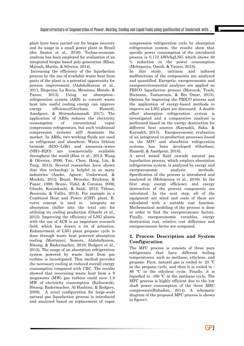
In the proposed modified MFC process, a NH3/ H2O absorption refrigeration system is used instead of the first compression refrigeration cycle, but other compression refrigeration cycles are remained unchanged.
More detail description about the process can be found in (Mehrpooya et al., 2016). Table 1presents the thermodynamic data for the material streams of the process.
Table 1. Thermodynamic specifications of the modified MFC process
Stream no. Temperature( C)
Pressure(bar)
Flow(kg.mol/h)
Physical exergy(kW)
Chemical exergy(kW)
Total exergy(kW)
1 26.85 65 6771 18666 1664325 16829922 -25.25 65 6771 12241 1664325 16834783 -85.35 65 6771 24170 1664325 16884964 -160.15 65 6771 32775 1664325 16971015 -166.1 1 6771 31526 1664325 16958526 -166.1 1 6303 30813 1596265 16270787 -166.1 1 468 469 68304 687748 31.39 1.2 53620 1563 1345297 13457999 31.98 1.3 53620 94 1345297 134539110 122.85 13 53620 18181 1345297 136340111 146.18 13 47358 21363 7543942 78613912 36.98 13 47358 593 754394 75498713 37.23 1.2 47358 259 754394 75465316 45.48 13 6261 10602 593004 60360717 33.97 13 6261 9528 593004 60253318 -24.42 13 6261 10141 593004 60314619 -29.55 1.2 6261 10060 593004 60306520 -29.42 1.2 6261 2302 593004 59530721 13.05 1.2 6261 738 593004 59374222 45.82 1.2 53620 2432 593004 134785823 -24.35 3.1 6927 5714 1345297 299571824 36.85 27.9 6927 14766 2990004 300477125 -21.49 27.9 6927 16586 2990004 300659026 -78.48 27.9 6927 19725 2990004 300972927 -90.27 3.1 6927 19038 2990004 300904228 -87.68 3.5 4882 5542 1224039 122958229 36.85 33.9 4882 11473 1224039 123551230 -21.29 33.9 4882 11705 1224039 123574331 -83.28 33.9 4882 15788 1224039 123982732 -154.05 33.9 4882 22649 1224039 124668833 -163.15 3.5 4882 22021 1224039 124606034 25 1.013 493703 121 427876 42799735 30 1.013 493703 440 427876 42831636 25 1.013 493703 234 285477 28571137 30 1.013 493703 393 285477 285871
6 Gas Processing Journal, Vol. 5, No. 1, 2017
GGPPJJ
3. Exergy Analysis Exergy is a measure of the maximum capacity of a system to perform useful work as it proceeds to a specified final state in equilibrium with its surroundings. Exergy is generally not conserved as energy, but destructed in the system. Exergy destruction is the measure of irreversibility that is the source of performance loss. Therefore, an exergy analysis assessing the magnitude of exergy destruction identifies the location, the magnitude and the source of thermodynamic inefficiencies in a thermal system (Dai, Wang, & Gao, 2009).In table1 physical and chemical exergy of the process material streams as well as their temperature, pressure and mass flow rate are presented. It should be noted that calculation of standard chemical exergy of the hydrocarbon streams is down based on the relations which are developed in(Sheikhi, Ghorbani, Shirmohammadi, & Hamedi, 2014, 2015). Also the data set for the standard chemical exergy of the other components is obtained from (Kotas, 2013).
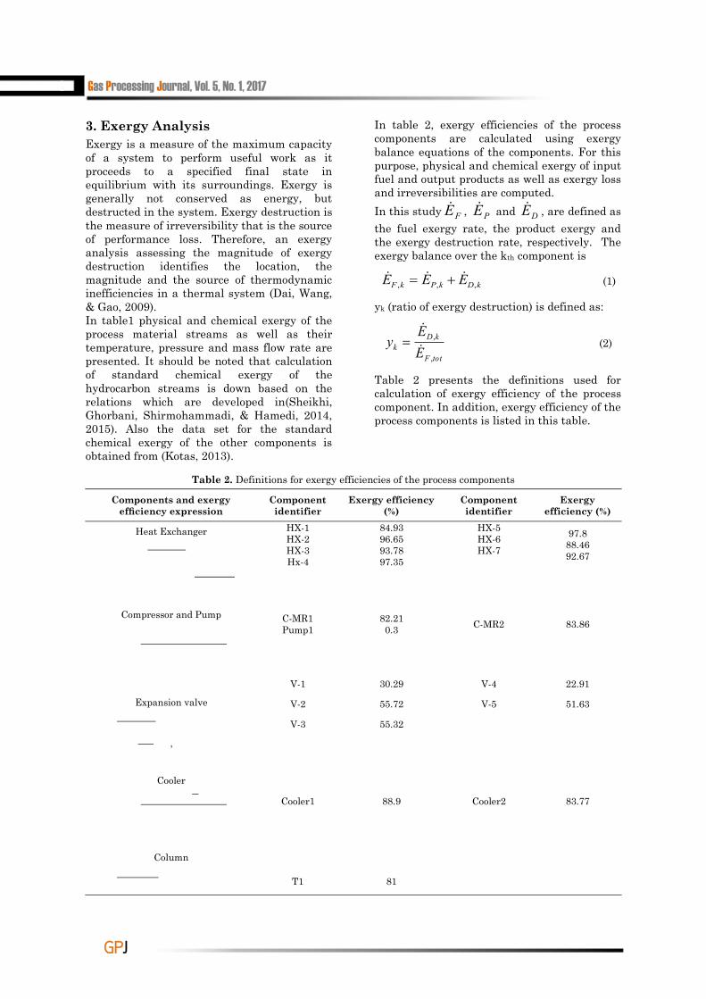
In table 2, exergy efficiencies of the process components are calculated using exergy balance equations of the components. For this purpose, physical and chemical exergy of input fuel and output products as well as exergy loss and irreversibilities are computed. In this study FE , PE and DE , are defined as the fuel exergy rate, the product exergy and the exergy destruction rate, respectively. The exergy balance over the kth component is
kDkPkF EEE ,,, (1)
yk (ratio of exergy destruction) is defined as:
totF
kDk E
Ey
,
,
(2)
Table 2 presents the definitions used for calculation of exergy efficiency of the process component. In addition, exergy efficiency of the process components is listed in this table.
Table 2. Definitions for exergy efficiencies of the process components
Exergy efficiency (%)
Component identifier
Exergy efficiency (%)
Component identifier
Components and exergy ef ciency expression
97.888.4692.67
HX-5HX-6HX-7
84.9396.6593.7897.35
HX-1HX-2HX-3Hx-4
Heat Exchanger
83.86C-MR282.210.3
C-MR1Pump1
Compressor and Pump
22.91V-430.29V-1
Expansion valve
,
51.63V-555.72V-2
55.32V-3
83.77Cooler288.9Cooler1
Cooler
Column
81T1
Superstructure of Cogeneration of Power, Heating, Cooling and Liquid Fuels using gasification of feedstock with … 7
GGPPJJ
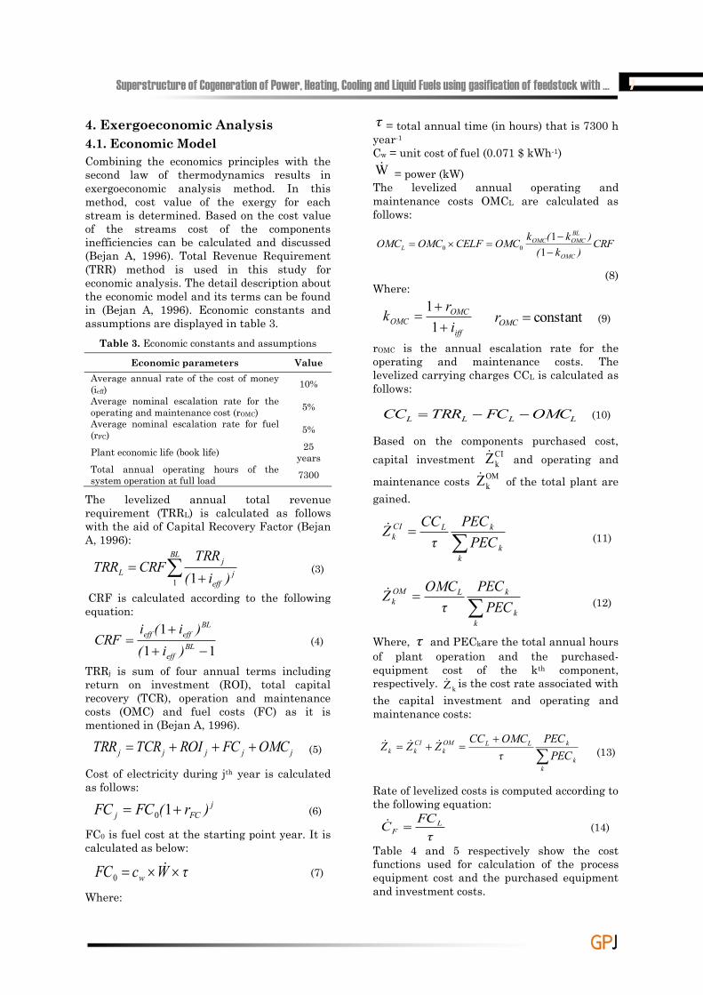
4. Exergoeconomic Analysis4.1. Economic Model Combining the economics principles with the second law of thermodynamics results in exergoeconomic analysis method. In this method, cost value of the exergy for each stream is determined. Based on the cost value of the streams cost of the components inefficiencies can be calculated and discussed (Bejan A, 1996). Total Revenue Requirement (TRR) method is used in this study for economic analysis. The detail description about the economic model and its terms can be found in (Bejan A, 1996). Economic constants and assumptions are displayed in table 3.
Table 3. Economic constants and assumptions
Economic parameters ValueAverage annual rate of the cost of money (ieff) 10%Average nominal escalation rate for the operating and maintenance cost (rOMC) 5%Average nominal escalation rate for fuel (rFC) 5%
Plant economic life (book life) 25 years
Total annual operating hours of the system operation at full load 7300
The levelized annual total revenue requirement (TRRL) is calculated as follows with the aid of Capital Recovery Factor (Bejan A, 1996):
BL
jeff
jL )i(
TRRCRFTRR
1 1(3)
CRF is calculated according to the following equation:
111
BL
eff
BLeffeff
)i()i(i
CRF (4)
TRRj is sum of four annual terms including return on investment (ROI), total capital recovery (TCR), operation and maintenance costs (OMC) and fuel costs (FC) as it is mentioned in (Bejan A, 1996).
jjjjj OMCFCROITCRTRR (5)
Cost of electricity during jth year is calculated as follows:
jFCj )r(FCFC 10 (6)
FC0 is fuel cost at the starting point year. It is calculated as below:
τWcFC w 0 (7)
Where:
τ = total annual time (in hours) that is 7300 h year-1
Cw = unit cost of fuel (0.071 $ kWh-1) W = power (kW) The levelized annual operating and maintenance costs OMCL are calculated as follows:
CRF)k()k(kOMCCELFOMCOMC
OMC
BLOMCOMC
L
1
100
(8) Where:
iff
OMCOMC i
rk
1
1constantOMCr (9)
rOMC is the annual escalation rate for the operating and maintenance costs. The levelized carrying charges CCL is calculated as follows:
LLLL OMCFCTRRCC (10)
Based on the components purchased cost, capital investment CI
kZ and operating and
maintenance costs OMkZ of the total plant are
gained.
kk
kLCIk PEC
PECτCCZ (11)
kk
kLOMk PEC
PECτ
OMCZ (12)
Where, τ and PECkare the total annual hours of plant operation and the purchased-equipment cost of the kth component, respectively. kZ is the cost rate associated with the capital investment and operating and maintenance costs:
kk
kLLOMk
CIkk PEC
PECτOMCCCZZZ
(13)
Rate of levelized costs is computed according to the following equation:
τFCC L
F (14)
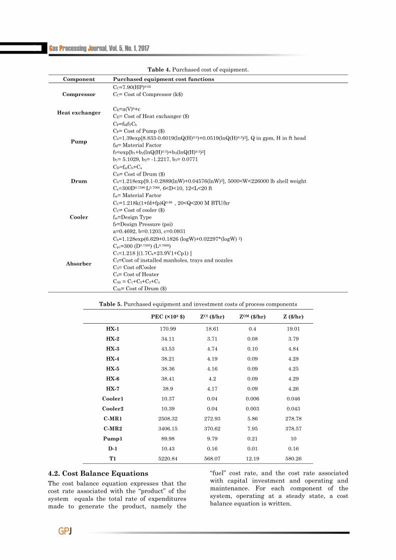
Table 4 and 5 respectively show the cost functions used for calculation of the process equipment cost and the purchased equipment and investment costs.
8 Gas Processing Journal, Vol. 5, No. 1, 2017
GGPPJJ
Table 4. Purchased cost of equipment.Component Purchased equipment cost functions
CompressorCC=7.90(HP)0.62
CC= Cost of Compressor (k$)
Heat exchanger CE=a(V)b+cCE= Cost of Heat exchanger ($)
Pump
CP=fMfTCb
CP= Cost of Pump ($)Cb=1.39exp[8.833-0.6019(lnQ(H)0.5)+0.0519(lnQ(H)0.5)2], Q in gpm, H in ft headfM= Material FactorfT=exp[b1+b2(lnQ(H)0.5)+b3(lnQ(H)0.5)2]b1= 5.1029, b2= -1.2217, b3= 0.0771
Drum
CD=fmCb+Ca
CD= Cost of Drum ($)Cb=1.218exp[9.1-0.2889(lnW)+0.04576(lnW)2], 5000<W<226000 lb shell weightCa=300D0.7396 L0.7066, 6<D<10, 12<L<20 ft fm= Material Factor
Cooler
CC=1.218k(1+fd+fp)Q0.86 , 20<Q<200 M BTU/hrCC= Cost of cooler ($)fm=Design TypefP=Design Pressure (psi)a=0.4692, b=0.1203, c=0.0931
Absorber
Cb=1.128exp(6.629+0.1826 (logW)+0.02297*(logW) 2)Cp1=300 (D0.7395) (L0.7068)C1=1.218 [(1.7Cb+23.9V1+Cp1) ]C2=Cost of installed manholes, trays and nozzlesC3= Cost ofCooler C4= Cost of HeaterCAb = C1+C2+C3+C4
CAb= Cost of Drum ($)
Table 5. Purchased equipment and investment costs of process components
PEC (×103 $) ZCI ($/hr) ZOM ($/hr) Z ($/hr)
HX-1 170.99 18.61 0.4 19.01
HX-2 34.11 3.71 0.08 3.79
HX-3 43.53 4.74 0.10 4.84
HX-4 38.21 4.19 0.09 4.28
HX-5 38.36 4.16 0.09 4.25
HX-6 38.41 4.2 0.09 4.29
HX-7 38.9 4.17 0.09 4.26
Cooler1 10.37 0.04 0.006 0.046
Cooler2 10.39 0.04 0.003 0.043
C-MR1 2508.32 272.93 5.86 278.78
C-MR2 3406.15 370.62 7.95 378.57
Pump1 89.98 9.79 0.21 10
D-1 10.43 0.16 0.01 0.16
T1 5220.84 568.07 12.19 580.26
4.2. Cost Balance Equations The cost balance equation expresses that the cost rate associated with the ―product‖ of the system equals the total rate of expenditures made to generate the product, namely the
―fuel‖ cost rate, and the cost rate associated with capital investment and operating and maintenance. For each component of the system, operating at a steady state, a cost balance equation is written.
Superstructure of Cogeneration of Power, Heating, Cooling and Liquid Fuels using gasification of feedstock with … 9
GGPPJJ
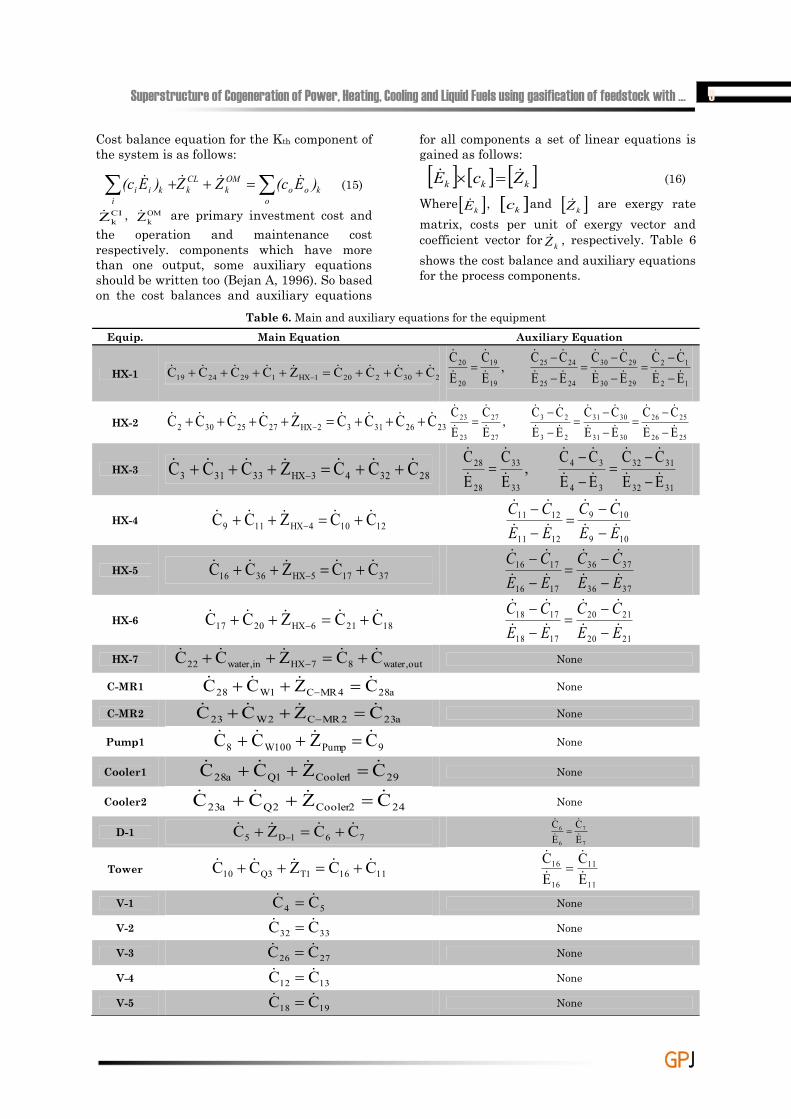
Cost balance equation for the Kth component of the system is as follows:
o
kooOMk
CLk
ikii )E(cZZ)E(c (15)
CIkZ , OM
kZ are primary investment cost and the operation and maintenance cost respectively. components which have more than one output, some auxiliary equations should be written too (Bejan A, 1996). So based on the cost balances and auxiliary equations
for all components a set of linear equations is gained as follows:
kkk ZcE (16)
Where kE , kc and kZ are exergy rate matrix, costs per unit of exergy vector and coefficient vector for kZ , respectively. Table 6 shows the cost balance and auxiliary equations for the process components.
Table 6. Main and auxiliary equations for the equipmentEquip. Main Equation Auxiliary Equation
HX-1 25302201HX1292419 CCCCZCCCC 12
12
2930
2930
2425
2425
19
19
20
20
EECC
EECC
EECC
,EC
EC
HX-2 23263132HX2725302 CCCCZCCCC 2526
2526
3031
3031
23
23
27
27
23
23
EECC
EECC
EECC
,EC
EC
HX-3 283243HX33313 CCCZCCC 3132
3132
34
34
33
33
28
28
EECC
EECC
,EC
EC
HX-4 12104HX119 CCZCC 109
109
1211
1211
EECC
EECC
HX-5 37175HX3616 CCZCC 3736
3736
1716
1716
EECC
EECC
HX-6 18216HX2017 CCZCC 2120
2120
1718
1718
EECC
EECC
HX-7 out,water87HXin,water22 CCZCC None
C-MR1 a284MRC1W28 CZCC None
C-MR2 a232MRC2W23 CZCC None
Pump1 9Pump100W8 CZCC None
Cooler1 291Cooler1Qa28 CZCC None
Cooler2 242Cooler2Qa23 CZCC None
D-1 761D5 CCZC 7
7
6
6
EC
EC
Tower 11161T3Q10 CCZCC 11
11
16
16
EC
EC
V-1 54 CC None
V-2 3332 CC None
V-3 2726 CC None
V-4 1312 CC None
V-5 1918 CC None
10 Gas Processing Journal, Vol. 5, No. 1, 2017
GGPPJJ
4.3. Exergoeconomic Variables
FE and pE are defined respectively fuel and product exergy rate for a component. On this basis, FC and PC are fuel cost rate and product cost rate respectively. In addition, for kth component of the system kFc , is average cost per unit of exergy of fuel according to the below equation.
F,k
F,kF,k E
Cc
(17)
In this way, product average cost per unit of exergy and cost of exergy destruction, for the kth component are defined as:
P,k
P,kP,k E
Cc
(18)
D,kF,kD,k EcC (19)
Relative cost difference is also defined as follows:
P,kF,k
k
k
k
F,k
F,kP,kk Ec
Zεε
ccc
r
1(20)
Exergoeconomic factor is the ratio of investments cost to the total investment plus cost of exergy destruction. It is computed with following equation:
D,kk
kk CZ
Zf
(21)
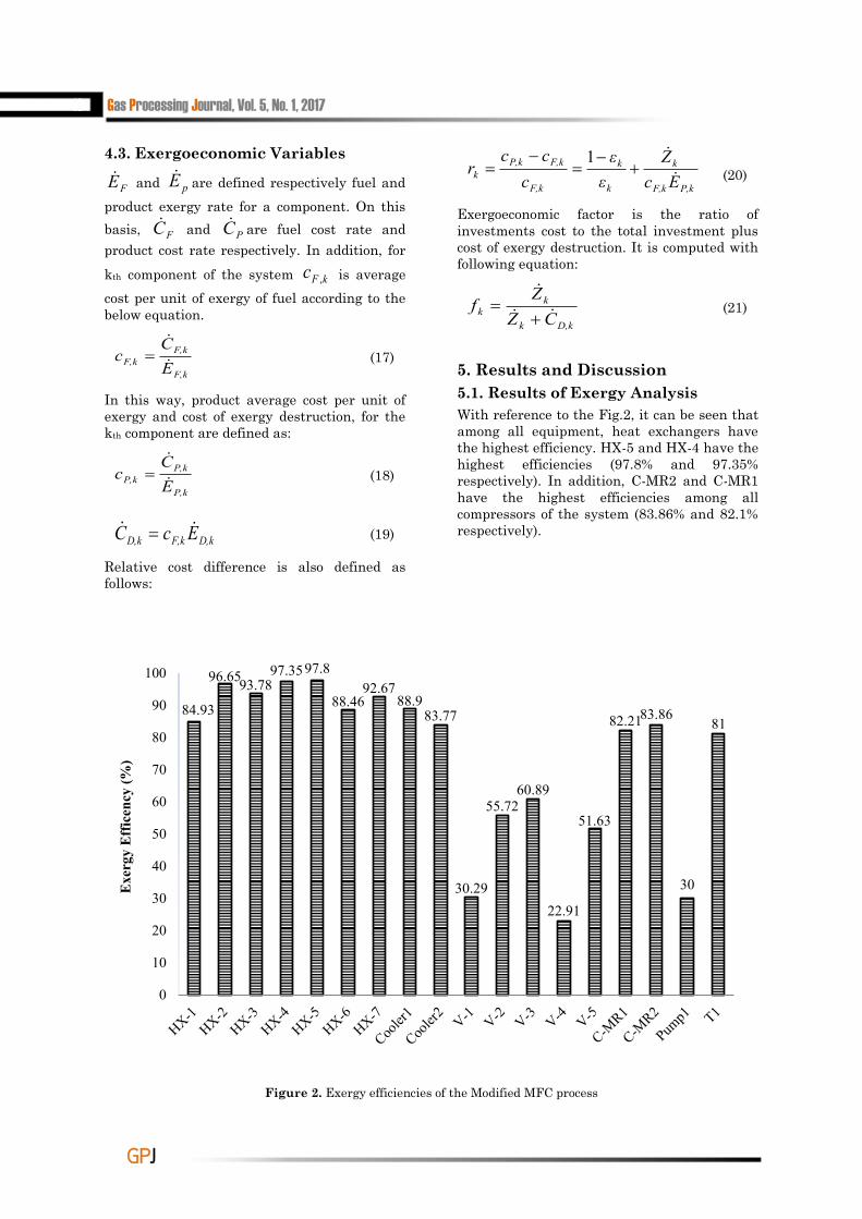
5. Results and Discussion 5.1. Results of Exergy Analysis With reference to the Fig.2, it can be seen that among all equipment, heat exchangers have the highest efficiency. HX-5 and HX-4 have the highest efficiencies (97.8% and 97.35% respectively). In addition, C-MR2 and C-MR1 have the highest efficiencies among all compressors of the system (83.86% and 82.1% respectively).
Figure 2. Exergy efficiencies of the Modified MFC process
84.93
96.6593.7897.3597.8
88.4692.67
88.983.77
30.29
55.7260.89
22.91
51.63
82.2183.86
30
81
0
10
20
30
40
50
60
70
80
90
100
Exe
rgy
Eff
icen
cy (%
)
Superstructure of Cogeneration of Power, Heating, Cooling and Liquid Fuels using gasification of feedstock with … 11
GGPPJJ
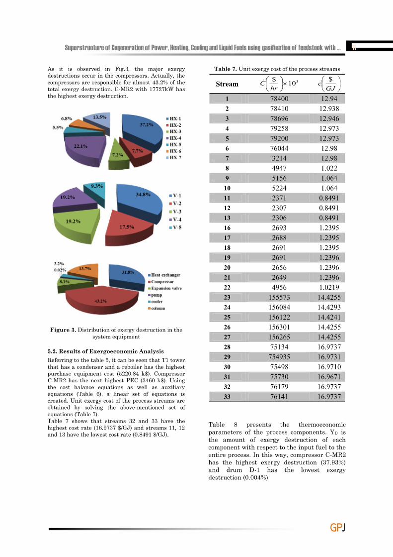
As it is observed in Fig.3, the major exergy destructions occur in the compressors. Actually, the compressors are responsible for almost 43.2% of the total exergy destruction. C-MR2 with 17727kW has the highest exergy destruction.
Figure 3. Distribution of exergy destruction in the system equipment
5.2. Results of Exergoeconomic Analysis Referring to the table 5, it can be seen that T1 tower that has a condenser and a reboiler has the highest purchase equipment cost (5220.84 k$). Compressor C-MR2 has the next highest PEC (3460 k$). Using the cost balance equations as well as auxiliary equations (Table 6), a linear set of equations is created. Unit exergy cost of the process streams are obtained by solving the above-mentioned set of equations (Table 7). Table 7 shows that streams 32 and 33 have the highest cost rate (16.9737 $/GJ) and streams 11, 12 and 13 have the lowest cost rate (0.8491 $/GJ).
Table 7. Unit exergy cost of the process streams
Stream 310$
hr
C
GJ
c $
1 78400 12.942 78410 12.9383 78696 12.9464 79258 12.9735 79200 12.9736 76044 12.987 3214 12.988 4947 1.0229 5156 1.064
10 5224 1.06411 2371 0.849112 2307 0.849113 2306 0.849116 2693 1.239517 2688 1.239518 2691 1.239519 2691 1.239620 2656 1.239621 2649 1.239622 4956 1.021923 155573 14.425524 156084 14.429325 156122 14.424126 156301 14.425527 156265 14.425528 75134 16.973729 754935 16.973130 75498 16.971031 75730 16.967132 76179 16.973733 76141 16.9737
Table 8 presents the thermoeconomic parameters of the process components. YD is the amount of exergy destruction of each component with respect to the input fuel to the entire process. In this way, compressor C-MR2 has the highest exergy destruction (37.93%) and drum D-1 has the lowest exergy destruction (0.004%)
12 Gas Processing Journal, Vol. 5, No. 1, 2017
GGPPJJ
Table 8. Results of exergy and exergoeconomic analysis of the modified MFC process
Component )kW(EF )kW(EP)kW(ED
hr$CF
hr$Cp
hr$CD
hr$Z %YD %r %f
HX-1 7758 2536 5222 34 53 18.99 19.01 11.17 37.4 50.1
HX-2 13323 12241 1082 692 696 3.79 3.79 2.31 94 49.6HX-3 16478 15465 1012 1007 1012 7.84 4.84 2.16 7.06 49.9HX-4 20769 17679 3090 63 67 4.25 4.28 6.61 25.34 50HX-5 1073 293 780 2689 2693 4.79 4.25 1.66 72.5 47HX-6 1564 612 952 3 7 4.25 4.29 2.03 0.014 49HX-7 1347729 1345391 1897 4947 4956 8.59 4.26 4.05 0.011 33.1
Cooler1 1235721 1235512 209 75494 75494 0.041 0.046 0.44 0.017 50.2Cooler2 3005978 3004771 1207 15684 15684 0.042 0.043 2.58 0.042 50.13C-MR1 3013445 1235721 1328 75215 75494 7108 278.78 2.84 0.48 3.7C-MR2 3013445 2995718 17727 155573 156216 642.78 378.57 37.93 0.3 37.1Pump1 1345789 1345799 9.7 2421 2431 10 10 0.020 0.016 50.01
D-1 1695852 1695850 2 79201 79259 58.49 0.16 0.004 0.074 0.27T1 1385394 1379364 6029 4485 5065 580.26 580.26 18.47 13.43 50.06
There is a specific procedure for thermoeconomic analysis and diagnosis of thermal cycles as mentioned below: First off, all of the components are sorted in descending order, based on their importance. The relative importance of each component is evaluated by the sum of DC and Z . As it can be seen in the table 9 below, compressor C-MR1 has the highest value (7386.78 $/hr)
Table 9. Components, based on their importance
Component
hr$Z
hr$CD
HX-1 38HX-2 7.58HX-3 12.68HX-4 8.53HX-5 9.04HX-6 8.54HX-7 12.85
Cooler1 0.087Cooler2 0.085C-MR1 7386.78C-MR2 1021.35Pump1 20
D-1 58.65T1 1160.52
Components are arranged in table 9, based on their relative importance and cost. In order to improve the system performance, it is more advantageous to work on the components with highest cost value. Contrary to the exergy analysis, in the exergoeconomic diagnosis, the impact of the components on the process costs can be revealed. Exergoeconomic factor (f) determines the relative importance of each component in the total cost of the system. If the exergoeconomic factor is high, then it should be checked whether it is economical to decrease the capital cost of the component or not. This is because, for these components, the initial investment cost is so high that their economic justification is in doubt. Table 10 shows the exergoeconomic factor of the process components. As it can be seen, cooler 1 and cooler 2 have the greatest Exergoeconomic factor (50.2% and 50.13% respectively). In these coolers, the initial capital costs are high and maybe using simpler and cheaper equipment is more economical.If the exergoeconomic factor of a component is too small, its efficiency should be increased even if its initial cost grows larger. This is because, in such components, low efficiency imposes a high cost to the system. In Table 10 the components are arranged based on the value of exergoeconomic factor. As it can be observed, drum D-1 and compressor C-MR1 with 0.27% and 3.7% have the lowest exergoeconomic factor. These components should be preferably be replaced with more efficient components since they have imposed relatively high cost to the entire system.
Superstructure of Cogeneration of Power, Heating, Cooling and Liquid Fuels using gasification of feedstock with … 13
GGPPJJ
Table 10. Exergoeconomic factor of the components
Component F(%)
Cooler1 50.2Cooler2 50.13
HX-1 50.1T1 50.06
Pump1 50.01HX-4 50HX-3 49.9HX-2 49.6HX-6 49HX-5 47
C-MR2 37.1HX-7 33.1
C-MR1 3.7D-1 0.27
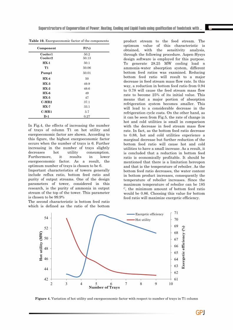
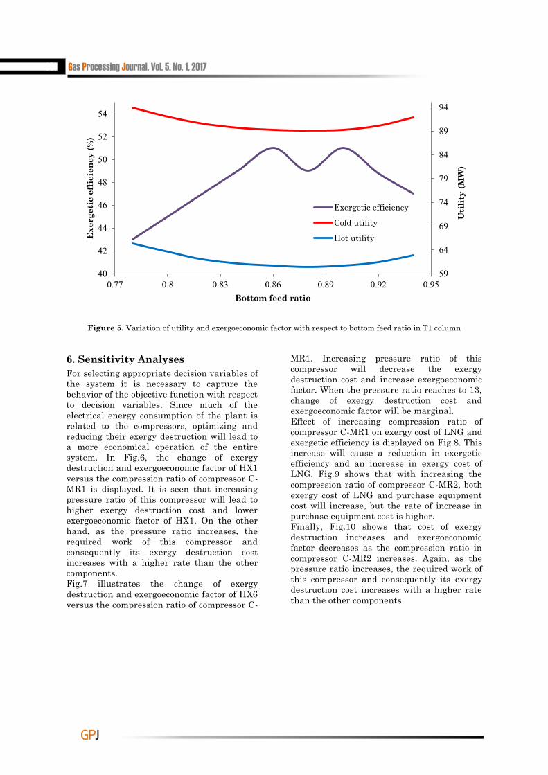
In Fig.4, the effects of increasing the number of trays of column T1 on hot utility and exergoeconomic factor are shown. According to this figure, the highest exergoeconomic factor occurs when the number of trays is 6. Further increasing in the number of trays slightly decreases hot utility consumption. Furthermore, it results in lower exergoeconomic factor. As a result, the optimum number of trays is chosen to be 6. Important characteristics of towers generally include reflux ratio, bottom feed ratio and purity of output streams. One of the design parameters of tower, considered in this research, is the purity of ammonia in output stream of the top of the tower. This parameter is chosen to be 99.9% The second characteristic is bottom feed ratio which is defined as the ratio of the bottom
product stream to the feed stream. The optimum value of this characteristic is obtained, with the sensitivity analysis, through the following procedure. Aspen-Hysys design software is employed for this purpose. To generate 28.25 MW cooling load n ammonia-water absorption system, different bottom feed ratios was examined. Reducing bottom feed ratio will result to a major decrease in feed stream mass flow rate. In this way, a reduction in bottom feed ratio from 0.94 to 0.78 will cause the feed stream mass flow rate to become 25% of its initial value. This means that a major portion of absorption refrigeration system becomes smaller. This will lead to a considerable decrease in the refrigeration cycle costs. On the other hand, as it can be seen from Fig.5, the rate of change in hot and cold utilities is small in comparison with the decrease in feed stream mass flow rate. In fact, as the bottom feed ratio decrease to 0.88, hot and cold utilities experience a marginal decrease but further reduction of the bottom feed ratio will cause hot and cold utilities to have a small increase. As a result, it is concluded that a reduction in bottom feed ratio is economically profitable. It should be mentioned that there is a limitation hereupon and that is the temperature of reboiler. As the bottom feed ratio decreases, the water content in bottom product increases, consequently the temperature of reboiler increases. Since the maximum temperature of reboiler can be 185 C, the minimum amount of bottom feed ratio would be 0.86. Choosing this value for bottom feed ratio will maximize exergetic efficiency.
Figure 4. Variation of hot utility and exergoeconomic factor with respect to number of trays in T1 column
61
62
63
64
65
66
67
68
69
70
71
42
44
46
48
50
52
54
2 3 4 5 6 7 8 9 10
Exe
rget
ic e
ffic
ienc
y (%
)
Hot
uti
lity
(MW
)
Number of Trays
Exergetic efficiencyHot utility
14 Gas Processing Journal, Vol. 5, No. 1, 2017
GGPPJJ
Figure 5. Variation of utility and exergoeconomic factor with respect to bottom feed ratio in T1 column
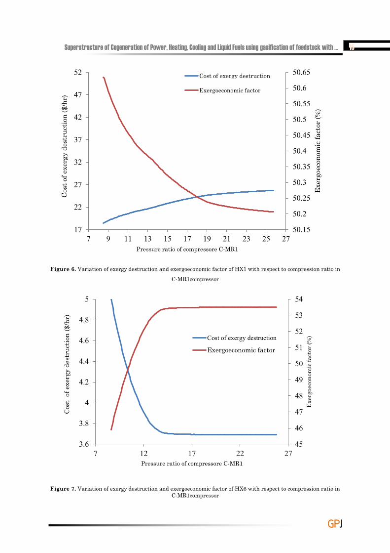
6. Sensitivity Analyses For selecting appropriate decision variables of the system it is necessary to capture the behavior of the objective function with respect to decision variables. Since much of the electrical energy consumption of the plant is related to the compressors, optimizing and reducing their exergy destruction will lead to a more economical operation of the entire system. In Fig.6, the change of exergy destruction and exergoeconomic factor of HX1 versus the compression ratio of compressor C-MR1 is displayed. It is seen that increasing pressure ratio of this compressor will lead to higher exergy destruction cost and lower exergoeconomic factor of HX1. On the other hand, as the pressure ratio increases, the required work of this compressor and consequently its exergy destruction cost increases with a higher rate than the other components. Fig.7 illustrates the change of exergy destruction and exergoeconomic factor of HX6 versus the compression ratio of compressor C-
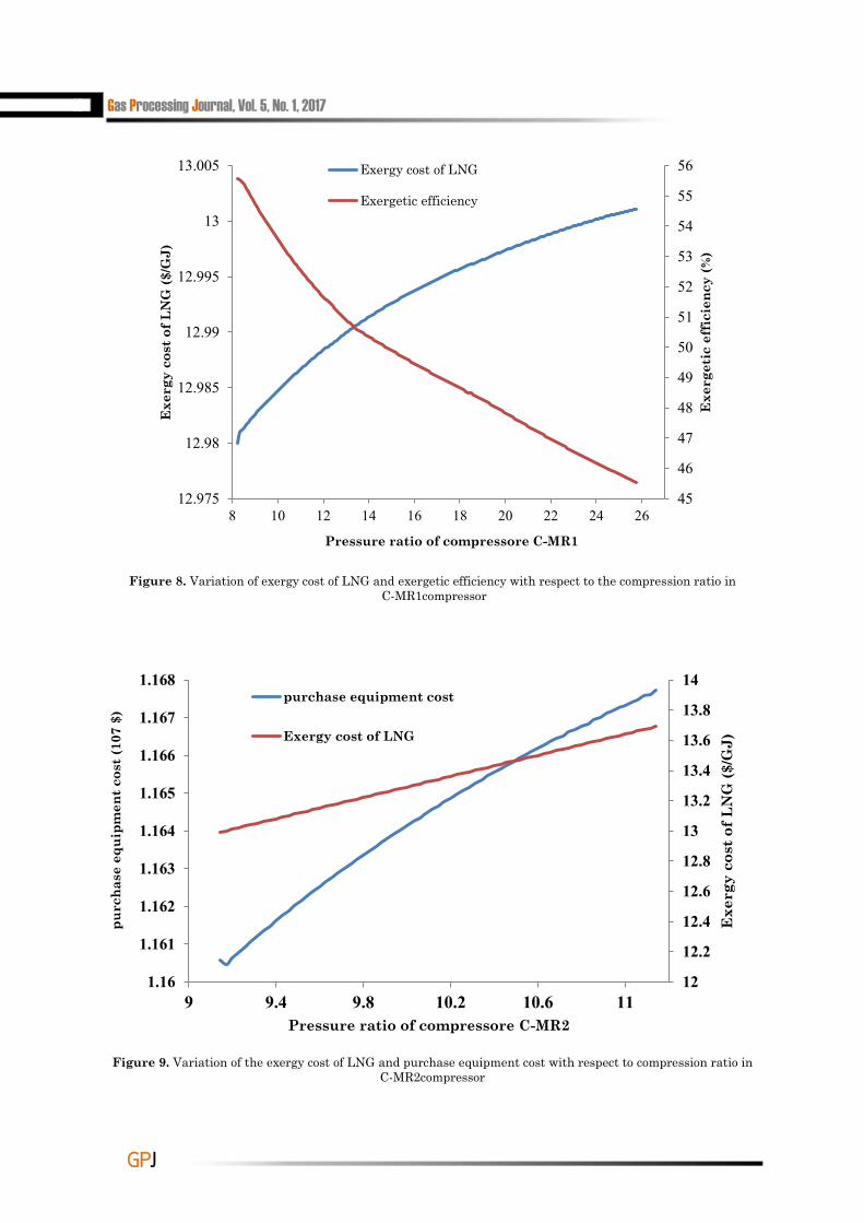
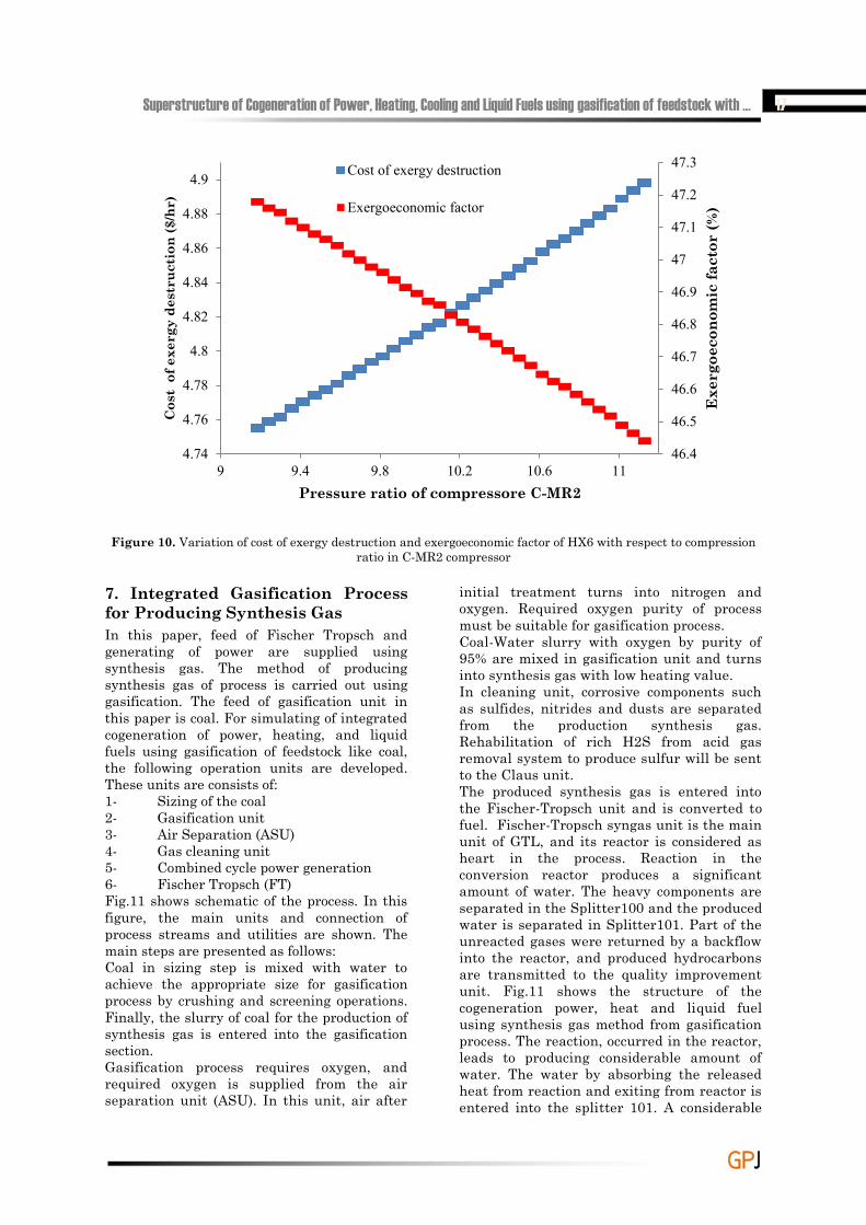
MR1. Increasing pressure ratio of this compressor will decrease the exergy destruction cost and increase exergoeconomic factor. When the pressure ratio reaches to 13, change of exergy destruction cost and exergoeconomic factor will be marginal. Effect of increasing compression ratio of compressor C-MR1 on exergy cost of LNG and exergetic efficiency is displayed on Fig.8. This increase will cause a reduction in exergetic efficiency and an increase in exergy cost of LNG. Fig.9 shows that with increasing the compression ratio of compressor C-MR2, both exergy cost of LNG and purchase equipment cost will increase, but the rate of increase in purchase equipment cost is higher. Finally, Fig.10 shows that cost of exergy destruction increases and exergoeconomic factor decreases as the compression ratio in compressor C-MR2 increases. Again, as the pressure ratio increases, the required work of this compressor and consequently its exergy destruction cost increases with a higher rate than the other components.
59
64
69
74
79
84
89
94
40
42
44
46
48
50
52
54
0.77 0.8 0.83 0.86 0.89 0.92 0.95
Uti
lity
(MW
)
Exe
rget
ic e
ffic
ienc
y (%
)
Bottom feed ratio
Exergetic efficiency
Cold utility
Hot utility
Superstructure of Cogeneration of Power, Heating, Cooling and Liquid Fuels using gasification of feedstock with … 15
GGPPJJ
Figure 6. Variation of exergy destruction and exergoeconomic factor of HX1 with respect to compression ratio in C-MR1compressor
Figure 7. Variation of exergy destruction and exergoeconomic factor of HX6 with respect to compression ratio in C-MR1compressor
50.15
50.2
50.25
50.3
50.35
50.4
50.45
50.5
50.55
50.6
50.65
17
22
27
32
37
42
47
52
7 9 11 13 15 17 19 21 23 25 27
Exer
goec
onom
ic fa
ctor
(%)
Cost
of e
xerg
y de
stru
ctio
n ($
/hr)
Pressure ratio of compressore C-MR1
Cost of exergy destruction
Exergoeconomic factor
45
46
47
48
49
50
51
52
53
54
3.6
3.8
4
4.2
4.4
4.6
4.8
5
7 12 17 22 27
Exer
goec
onom
ic fa
ctor
(%)
Cost
of e
xerg
y de
stru
ctio
n ($
/hr)
Pressure ratio of compressore C-MR1
Cost of exergy destruction
Exergoeconomic factor
16 Gas Processing Journal, Vol. 5, No. 1, 2017
GGPPJJ
Figure 8. Variation of exergy cost of LNG and exergetic efficiency with respect to the compression ratio in C-MR1compressor
Figure 9. Variation of the exergy cost of LNG and purchase equipment cost with respect to compression ratio in C-MR2compressor
12
12.2
12.4
12.6
12.8
13
13.2
13.4
13.6
13.8
14
1.16
1.161
1.162
1.163
1.164
1.165
1.166
1.167
1.168
9 9.4 9.8 10.2 10.6 11
Exe
rgy
cost
of L
NG
($/G
J)
purc
hase
equ
ipm
ent c
ost (
107
$)
Pressure ratio of compressore C-MR2
purchase equipment cost
Exergy cost of LNG
45
46
47
48
49
50
51
52
53
54
55
56
12.975
12.98
12.985
12.99
12.995
13
13.005
8 10 12 14 16 18 20 22 24 26
Exe
rget
ic e
ffic
ienc
y (%
)
Exe
rgy
cost
of L
NG
($/G
J)
Pressure ratio of compressore C-MR1
Exergy cost of LNG
Exergetic efficiency
Superstructure of Cogeneration of Power, Heating, Cooling and Liquid Fuels using gasification of feedstock with … 17
GGPPJJ
Figure 10. Variation of cost of exergy destruction and exergoeconomic factor of HX6 with respect to compression ratio in C-MR2 compressor
7. Integrated Gasification Process for Producing Synthesis Gas In this paper, feed of Fischer Tropsch and generating of power are supplied using synthesis gas. The method of producing synthesis gas of process is carried out using gasification. The feed of gasification unit in this paper is coal. For simulating of integrated cogeneration of power, heating, and liquid fuels using gasification of feedstock like coal, the following operation units are developed. These units are consists of: 1- Sizing of the coal2- Gasification unit3- Air Separation (ASU)4- Gas cleaning unit 5- Combined cycle power generation 6- Fischer Tropsch (FT) Fig.11 shows schematic of the process. In this figure, the main units and connection of process streams and utilities are shown. The main steps are presented as follows: Coal in sizing step is mixed with water to achieve the appropriate size for gasification process by crushing and screening operations. Finally, the slurry of coal for the production of synthesis gas is entered into the gasification section. Gasification process requires oxygen, and required oxygen is supplied from the air separation unit (ASU). In this unit, air after
initial treatment turns into nitrogen and oxygen. Required oxygen purity of process must be suitable for gasification process. Coal-Water slurry with oxygen by purity of 95% are mixed in gasification unit and turns into synthesis gas with low heating value. In cleaning unit, corrosive components such as sulfides, nitrides and dusts are separated from the production synthesis gas. Rehabilitation of rich H2S from acid gas removal system to produce sulfur will be sent to the Claus unit. The produced synthesis gas is entered into the Fischer-Tropsch unit and is converted to fuel. Fischer-Tropsch syngas unit is the main unit of GTL, and its reactor is considered as heart in the process. Reaction in the conversion reactor produces a significant amount of water. The heavy components are separated in the Splitter100 and the produced water is separated in Splitter101. Part of the unreacted gases were returned by a backflow into the reactor, and produced hydrocarbons are transmitted to the quality improvement unit. Fig.11 shows the structure of the cogeneration power, heat and liquid fuel using synthesis gas method from gasification process. The reaction, occurred in the reactor, leads to producing considerable amount of water. The water by absorbing the released heat from reaction and exiting from reactor is entered into the splitter 101. A considerable
46.4
46.5
46.6
46.7
46.8
46.9
47
47.1
47.2
47.3
4.74
4.76
4.78
4.8
4.82
4.84
4.86
4.88
4.9
9 9.4 9.8 10.2 10.6 11
Exe
rgoe
cono
mic
fact
or (%
)
Cos
t of
exe
rgy
dest
ruct
ion
($/h
r)
Pressure ratio of compressore C-MR2
Cost of exergy destruction
Exergoeconomic factor

18 Gas Processing Journal, Vol. 5, No. 1, 2017
GGPPJJ
amount of produced heat by reaction is exited which has had high energy. On the other hand, the reactor must have a constant temperature and it is done with the water cycle within a shell around the reactor. The shell is shown Fig.11 along with the exchanger HX12. Stream of Water 1 at the temperature of 25 ºC and pressure of 500 kPa is flown into the P101 pump and as stream of 601 at the pressure of 3200 kPa and temperature of 25.12 ºC is mixed with water stream exited from Splitter101 at the pressure of 3200 kPa and temperature of 220 ºC. Stream of 604 at the temperature of 640.8 ºC and pressure of 100 bar is employed for pre-heating of mixture of natural gas, oxygen and water vapor in the HX10. Stream of 605 at the temperature of 508.6 ºC and pressure of 100 bar is entered into a steam turbine and with generation of power using stream of 606 at the temperature of 207 ºC and pressure of 500 kPa is exited. Almost 18% of the 606 as stream of 607 with the loss of 56.71 kW in
heat exchanger of HX11 can provide the amount of heat required for Splitter100. Stream 608 with the loss of 6605 kW in the heat exchanger of HX13 can supply the amount of heat required for Splitter101. Stream of 609 at the temperature of 153.4 ºC and pressure of 500 kPa is mixed with stream of 613 which is at the temperature of 261.6 ºC and pressure of 500 kPa. The mixed stream i.e. stream of 614 is entered into the HX14. Stream of 614 after absorbing heat from the reactor Fischer-Tropsch (stream 107) is exited from exchanger HX14. Stream of 610 at the temperature and pressure of 159.8 ºC and 500 kPa as a hot steam is entered into the reboiler of separation tower of absorption refrigeration cycle and supplied required heating as much as 21350 kW. Approximately 66% of the stream of 611 as stream of water1 is used to provide closed cycle system. Integrated structure, presented in Fig.11, is employed for supplying power and hear of integrated structure of LNG production.
Figure 11. Schematic of integrated structure of CHP and liquid fuels from gasification of feedstock with primary material of coal using Fischer-Tropsch synthesis
Superstructure of Cogeneration of Power, Heating, Cooling and Liquid Fuels using gasification of feedstock with … 19
GGPPJJ
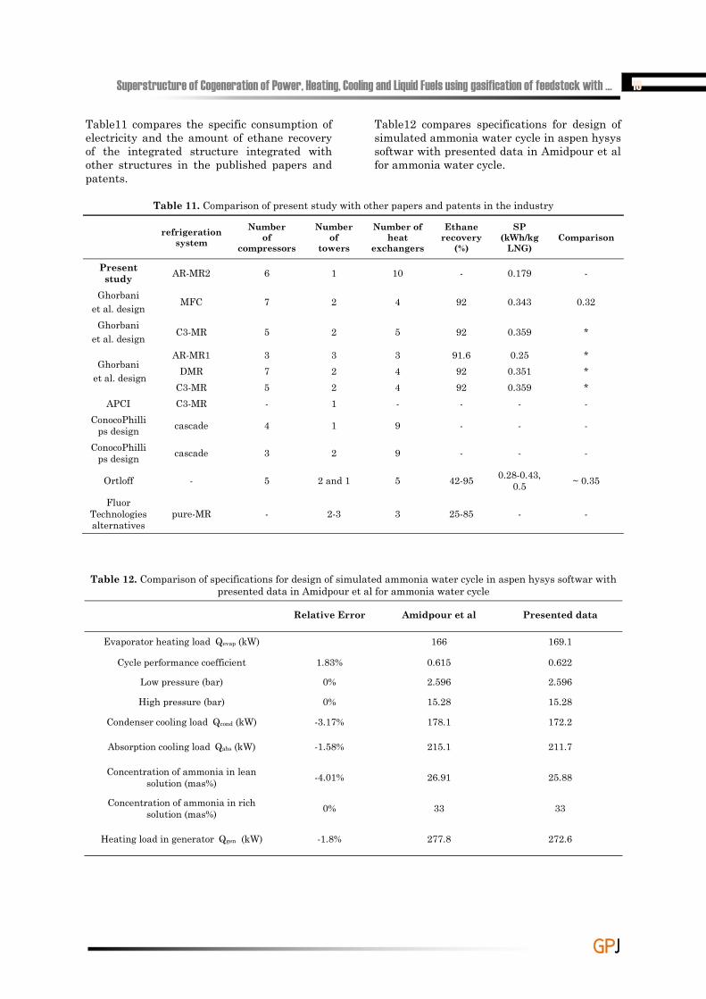
Table11 compares the specific consumption of electricity and the amount of ethane recovery of the integrated structure integrated with other structures in the published papers and patents.
Table12 compares specifications for design of simulated ammonia water cycle in aspen hysys softwar with presented data in Amidpour et al for ammonia water cycle.
Table 11. Comparison of present study with other papers and patents in the industry
refrigerationsystem
Numberof
compressors
Number of
towers
Number of heat
exchangers
Ethanerecovery
(%)
SP(kWh/kg
LNG)Comparison
Present study AR-MR2 6 1 10 - 0.179 -
Ghorbani et al. design MFC 7 2 4 92 0.343 0.32
Ghorbani et al. design C3-MR 5 2 5 92 0.359 *
Ghorbaniet al. design
AR-MR1 3 3 3 91.6 0.25 *DMR 7 2 4 92 0.351 *
C3-MR 5 2 4 92 0.359 *APCI C3-MR - 1 - - - -
ConocoPhillips design cascade 4 1 9 - - -
ConocoPhillips design cascade 3 2 9 - - -
Ortloff - 5 2 and 1 5 42-95 0.28-0.43, 0.5 ~ 0.35
Fluor Technologies alternatives
pure-MR - 2-3 3 25-85 - -
Table 12. Comparison of specifications for design of simulated ammonia water cycle in aspen hysys softwar with presented data in Amidpour et al for ammonia water cycle
Presented dataAmidpour et alRelative Error
169.1166Evaporator heating load Qevap (kW)
0.6220.6151.83%Cycle performance coefficient
2.5962.5960%Low pressure (bar)
15.2815.280%High pressure (bar)
172.2178.1-3.17%Condenser cooling load Qcond (kW)
211.7215.1-1.58%Absorption cooling load Qabs (kW)
25.8826.91-4.01%Concentration of ammonia in lean solution (mas%)
33330%Concentration of ammonia in rich solution (mas%)
272.6277.8-1.8%Heating load in generator Qgen (kW)
20 Gas Processing Journal, Vol. 5, No. 1, 2017
GGPPJJ
8. Conclusions In this study, a novel mixed fluid cascade natural gas liquefaction process was studied with exergoeconomic analysis method. The results are summarized as follows: 1- Highest exergy destruction in the process belongs to the compressors. As the exergy destruction in the compressors directly affects the required power in the process, its reduction can drastically decreases the operating costs of the plant. 2- Exergoeconomic shows that water coolers, heat exchanger HX-1, tower T1 and pump P1 have the highest exergoeconomic factor, respectively. Consequently, it can impose high initial investment cost to the plant. It is advisable to replace these equipment with cheaper ones. Efficiency improvement of compressors C-MR1 and C-MR2 should be considered, even though that will probably result in higher initial investment. Heat exchangers HX-5 and HX-6 are the next candidates for improvement. 3- Sensitivity analysis shows that the optimum number of trays is 6, and the best value for bottom feed ratio is 0.86. These values will result in best exergetic efficiency and optimum utility consumption.
Nomenclature Q Heat duty (kW)r Relative cost difference (%)c unit exergy cost ($/kJ)C exergy cost rate ($/h)m Mass flow rate (kg/s)
rFCannual escalation rate for the fuel cost
ROI Return on investmentcw
Unit cost of the generated electricity ($/kW)
e Specific flow exergy (kJ/kgmole)
Ė Exergy rate (kW)Ex Exergy (kW)F Exergoeconomic factor (%)I Irreversibility (kW)ieff average annual discount
rate j jth year of operationm Number of cold streams n Number of hot streamsrOM
Annual escalation rate for the O&M cost
W Power (kW)W Exergy destruction ratioAbbreviationsAC Air cooler
TCR Total capital recoveryTRR Total revenue requirementC CompressorMR Mixed RefrigerantV Expansion valveBL book lifeCOP Coefficient of PerformanceNG Natural GasLNG Liquefied Natural GasMFC Mixed Fluid CascadeSPC Specific Power
ConsumptionMR Mixed RefrigerantF Phase separatorC Cold boxP PumpE ExchangerK CompressorV ValveCC Carrying chargeCRF capital recovery factorOMC Operating and
maintenance costPEC Purchase equipment cost
($)FC Fuel cost ($/s)CRC compression refrigeration
cyclesubscriptsa airav averagecw Cooling waterf Fuelp product0 index for first year of
operationa Airc ColdD Destructionh Hoti Inletk kth componentL levelizedSuperscriptsCI Capital investmentOM Operating and
maintenance
ReferencesAdams, P. W. R., & McManus, M. C. (2014).
Small-scale biomass gasification CHP utilisation in industry: Energy and environmental evaluation. Sustainable Energy Technologies and Assessments, 6, 129-140. doi:https://doi.org/ 10.1016/j.seta.2014.02.002
Alabdulkarem, A., Mortazavi, A., Hwang, Y., Radermacher, R., & Rogers, P. (2011). Optimization of propane pre-cooled mixed refrigerant LNG plant. Applied
Superstructure of Cogeneration of Power, Heating, Cooling and Liquid Fuels using gasification of feedstock with … 21
GGPPJJ
Thermal Engineering, 31(6), 1091-1098.
Amidpour, M., Hamedi, M., Mafi, M., Ghorbani, B., Shirmohammadi, R., & Salimi, M. (2015). Sensitivity analysis, economic optimization, and configuration design of mixed refrigerant cycles by NLP techniques. Journal of Natural Gas Science and Engineering, 24, 144-155.
Aneke, M., Agnew, B., Underwood, C., & Menkiti, M. (2012). Thermodynamic analysis of alternative refrigeration cycles driven from waste heat in a food processing application. international journal of refrigeration, 35(5), 1349-1358.
Avidan, A. A., Gardner, R. E., Nelson, D., Borrelli, E. N., & Rethore, T. J. (1997). LNG links remote supplies and markets. Journal Name: Oil and Gas Journal; Journal Volume: 95; Journal Issue: 22; Other Information: PBD: 2 Jun 1997, Medium: X; Size: pp. 54-59.
Bahadori, A. (2014). Chapter 13 - Liquefied Natural Gas (LNG) Natural Gas Processing (pp. 591-632). Boston: Gulf Professional Publishing.
Bejan A, T. G., Moran M. (1996). Thermal Design and Optimization: Wiley.
Berger, E., Forg, W., Heiersted, R., & Paurola, P. (2003). The Snohvit Project: The MFC®(Mixed Fluid Cascade) Process for the first European Baseload LNG Production Plant. Linde Technology, 12-23.
Brant, B., Brueske, S., Erickson, D., & Papar, R. (1998). New waste-heat refrigeration unit cuts flaring, reduces pollution. Oil and Gas Journal, 96(20).
Bruno, J., Vidal, A., & Coronas, A. (2006). Improvement of the raw gas drying process in olefin plants using an absorption cooling system driven by quench oil waste heat. Energy Conversion and Management, 47(1), 97-113.
Dai, Y., Wang, J., & Gao, L. (2009). Exergy analysis, parametric analysis and optimization for a novel combined power and ejector refrigeration cycle. Applied Thermal Engineering, 29(10), 1983-1990. doi:http://dx.doi.org/ 10.1016/j.applthermaleng.2008.09.016
Dispenza, A., La Rocca, V., Messineo, A., Morale, M., & Panno, D. (2013).
Absorption equipment for energy savings: A case study in Sicily. Sustainable Energy Technologies and Assessments, 3, 17-26.
dos Santos, I. F. S., Vieira, N. D. B., Barros, R. M., Filho, G. L. T., Soares, D. M., & Alves, L. V. (2016). Economic and CO2 avoided emissions analysis of WWTP biogas recovery and its use in a small power plant in Brazil. Sustainable Energy Technologies and Assessments, 17, 77-84. doi:https://doi.org/10.1016/ j.seta.2016.08.003
Ghaebi, H., Karimkashi, S., & Saidi, M. (2012). Integration of an absorption chiller in a total CHP site for utilizing its cooling production potential based on R-curve concept. International Journal of Refrigeration, 35(5), 1384-1392.
Ghorbani, B., Hamedi, M.-H., & Amidpour, M. (2016). Exergoeconomic Evaluation of an Integrated Nitrogen Rejection Unit with LNG and NGL Co-Production Processes Based on the MFC and Absorbtion Refrigeration Systems. Gas Processing, 4(1), 1-28.
Ghorbani, B., Hamedi, M.-H., Amidpour, M., & Shirmohammadi, R. (2017). Implementing absorption refrigeration cycle in lieu of DMR and C3MR cycles in the integrated NGL, LNG and NRU unit. International Journal of Refrigeration, 77, 20-38.
Ghorbani, B., Hamedi, M.-H., Shirmohammadi, R., Hamedi, M., & Mehrpooya, M. (2016). Exergoeconomic analysis and multi-objective Pareto optimization of the C3MR liquefaction process. Sustainable Energy Technologies and Assessments, 17, 56-67.
Ghorbani, B., Hamedi, M., Shirmohammadi, R., Mehrpooya, M., & Hamedi, M.-H. (2016). A novel multi-hybrid model for estimating optimal viscosity correlations of Iranian crude oil. Journal of Petroleum Science and Engineering, 142, 68-76. doi:https://doi.org/10.1016/j.petrol.2016.01.041
Ghorbani, B., Mafi, M., Shirmohammadi, R., Hamedi, M.-H., & Amidpour, M. (2014). Optimization of operation parameters of refrigeration cycle using particle swarm and NLP techniques.
22 Gas Processing Journal, Vol. 5, No. 1, 2017
GGPPJJ
Journal of Natural Gas Science and Engineering, 21, 779-790.
Han, W., Sun, L., Zheng, D., Jin, H., Ma, S., & Jing, X. (2013). New hybrid absorption–compression refrigeration system based on cascade use of mid-temperature waste heat. Applied Energy, 106, 383-390.
Hasan, M., Karimi, I., & Alfadala, H. (2009). Optimizing compressor operations in an LNG plant. Paper presented at the Proceedings of the 1st annual gas processing symposium.
Hasan, M. F., Razib, M. S., & Karimi, I. (2009). Optimization of compressor networks in LNG operations. Computer Aided Chemical Engineering, 27, 1767-1772.
Hwang, J.-H., Roh, M.-I., & Lee, K.-Y. (2013). Determination of the optimal operating conditions of the dual mixed refrigerant cycle for the LNG FPSO topside liquefaction process. Computers & Chemical Engineering, 49, 25-36.
Jensen, J. B., & Skogestad, S. (2006). Optimal operation of a mixed fluid cascade LNG plant. In W. Marquardt & C. Pantelides (Eds.), Computer Aided Chemical Engineering (Vol. Volume 21, pp. 1569-1574): Elsevier.
Kalinowski, P., Hwang, Y., Radermacher, R., Al Hashimi, S., & Rodgers, P. (2009). Application of waste heat powered absorption refrigeration system to the LNG recovery process. international journal of refrigeration, 32(4), 687-694.
Kanoğlu, M. (2001). Cryogenic turbine efficiencies. Exergy, An International Journal, 1(3), 202-208.
Kaynakli, O., Saka, K., & Kaynakli, F. (2015). Energy and exergy analysis of a double effect absorption refrigeration system based on different heat sources. Energy Conversion and Management, 106, 21-30. doi:http://dx.doi.org/ 10.1016/j.enconman.2015.09.010
Khan, E. U., Mainali, B., Martin, A., & Silveira, S. (2014). Techno-economic analysis of small scale biogas based polygeneration systems: Bangladesh case study. Sustainable Energy Technologies and Assessments, 7, 68-78.
Kotas, T. J. (2013). The exergy method of thermal plant analysis: Elsevier.
Mehrpooya, M., Omidi, M., & Vatani, A. (2016). Novel mixed fluid cascade natural gas liquefaction process configuration using absorption refrigeration system. Applied Thermal Engineering, 98, 591-604. doi:http://dx.doi.org/10.1016/j.applthermaleng.2015.12.032
Morosuk, T., Tesch, S., Hiemann, A., Tsatsaronis, G., & Bin Omar, N. (2015). Evaluation of the PRICO liquefaction process using exergy-based methods. Journal of Natural Gas Science and Engineering, 27, Part 1, 23-31. doi:http://dx.doi.org/10.1016/ j.jngse.2015.02.007
Mortazavi, A., Somers, C., Alabdulkarem, A., Hwang, Y., & Radermacher, R. (2010). Enhancement of APCI cycle efficiency with absorption chillers. Energy, 35(9), 3877-3882.
Petrakopoulou, F., Tsatsaronis, G., & Morosuk, T. (2013). Evaluation of a power plant with chemical looping combustion using an advanced exergoeconomic analysis. Sustainable Energy Technologies and Assessments, 3, 9-16. doi:http://dx.doi.org/10.1016/j.seta.2013.05.001
Raj, R., Suman, R., Ghandehariun, S., Kumar, A., & Tiwari, M. K. (2016). A techno-economic assessment of the liquefied natural gas (LNG) production facilities in Western Canada. Sustainable Energy Technologies and Assessments, 18, 140-152.
Rodgers, P., Mortazavi, A., Eveloy, V., Al-Hashimi, S., Hwang, Y., & Radermacher, R. (2012). Enhancement of LNG plant propane cycle through waste heat powered absorption cooling. Applied Thermal Engineering, 48, 41-53.
Salomón, M., Gomez, M. F., & Martin, A. (2013). Technical polygeneration potential in palm oil mills in Colombia: A case study. Sustainable Energy Technologies and Assessments, 3, 40-52. doi:https://doi.org/10.1016/j.seta. 2013.05.003
Sheikhi, S., Ghorbani, B., Shirmohammadi, R., & Hamedi, M.-H. (2014). Thermodynamic and Economic Optimization of a Refrigeration Cycle for Separation Units in the Petrochemical Plants Using Pinch
Superstructure of Cogeneration of Power, Heating, Cooling and Liquid Fuels using gasification of feedstock with … 23
GGPPJJ
Technology and Exergy Syntheses Analysis. Gas Processing Journal, 2(2), 39-52. Retrieved from http://uijs.ui.ac.ir/gpj/browse.php?a_code=A-10-350-1&slc_lang=en&sid=1
Sheikhi, S., Ghorbani, B., Shirmohammadi, R., & Hamedi, M.-H. (2015). Advanced Exergy Evaluation of an Integrated Separation Process with Optimized Refrigeration System. Gas Processing Journal, 3(1), 1-10.
Shirmohammadi, R., Ghorbani, B., Hamedi, M., Hamedi, M.-H., & Romeo, L. M. (2015). Optimization of mixed refrigerant systems in low temperature applications by means of group method of data handling (GMDH). Journal of Natural Gas Science and Engineering, 26, 303-312.
Stockmann, R., Forg, W., Bolt, M., Steinbauer, M., Pfeiffer, C., Paurola, P., . . . Sorensen, O. (2001). Method for liquefying a stream rich in hydrocarbons: Google Patents.
Táboas, F., Bourouis, M., & Vallès, M. (2014). Analysis of ammonia/water and ammonia/salt mixture absorption cycles for refrigeration purposes in fishing ships. Applied Thermal Engineering, 66(1), 603-611.
Venkatarathnam, G., & Timmerhaus, K. D. (2008). Cryogenic mixed refrigerant processes: Springer.
Waldmann, I. (2008). Evaluation of process systems for floating LNG production units. Paper presented at the Tekna conference.
Wang, R., & Oliveira, R. (2006). Adsorption refrigeration—an efficient way to make good use of waste heat and solar energy. Progress in Energy and Combustion Science, 32(4), 424-458.
Xu, X., Liu, J., Jiang, C., & Cao, L. (2013). The correlation between mixed refrigerant composition and ambient conditions in the PRICO LNG process. Applied Energy, 102, 1127-1136.
Xydis, G., Nanaki, E., & Koroneos, C. (2013). Exergy analysis of biogas production from a municipal solid waste landfill.
Sustainable Energy Technologies and Assessments, 4, 20-28. doi:http://dx.doi.org/10.1016/j.seta.2013.08.003
Yan, X., Chen, G., Hong, D., Lin, S., & Tang, L. (2013). A novel absorption refrigeration cycle for heat sources with large temperature change. Applied Thermal Engineering, 52(1), 179-186.
Brostow, A.A. and M.J. Roberts, Integrated NGL recovery in the production of liquefied natural gas. 2006, Google Patents.
Roberts, M.J. and A.A. Brostow, Integrated NGL Recovery And Liquefied Natural Gas Production. 2010, Google Patents.
Ransbarger, W.L., Intermediate pressure LNG refluxed NGL recovery process. 2006, Google Patents.
Qualls, W., et al., Lng facility with integrated ngl extraction technology for enhanced ngl recovery and product flexibility. 2006, Google Patents.
Cuellar, K.T., et al., CO-PRODUCING LNG FROM CRYOGENIC NGL RECOVERY PLANTS. 2002.
Martinez, T.L., et al., Liquefied natural gas and hydrocarbon gas processing. 2014, Google Patents.
Mak, J. and C. Graham, Configurations and methods of integrated NGL recovery and LNG liquefaction. 2006, Google Patents
Ghorbani, B., Hamedi, M.-H., Amidpour, M., & Mehrpooya, M. (2016). Cascade refrigeration systems in integrated cryogenic natural gas process (natural gas liquids (NGL), liquefied natural gas (LNG) and nitrogen rejection unit (NRU)). Energy, 115, 88-106.
Ghorbani, B., Hamedi, M.-H., & Amidpour, M. (2016). Development and optimization of an integrated process configuration for natural gas liquefaction (LNG) and natural gas liquids (NGL) recovery with a nitrogen rejection unit (NRU). Journal of Natural Gas Science and Engineering, 34, 590-603.


![CO2 Refrigerant for Industrial Refrigeration[1]](https://img.pdfslide.us/doc/110x75/5526f6f9550346e1358b462a/co2-refrigerant-for-industrial-refrigeration1.jpg)