Embed Size (px)
DESCRIPTION
Gas Furnace Controls. Part 4. Gas furnace controls – part 4 will review Group IV of the four groups of controls systems. The next slide will show all four groups as a review. Please refer to page A1 in your Student Handout Packet. The four groups are as follows :. - PowerPoint PPT Presentation
Citation preview
Gas Furnace Controls
Part 4

Gas furnace controls – part 4 will review Group IV of the
four groups of controls systems. The next slide will show
all four groups as a review.
Please refer to page A1 in your Student Handout Packet

The four groups are as follows:
I. Manual Ignition with Standing Pilot and
Pilot Heat Switch
II. Manual Ignition with Standing Pilot and
Thermocouple
III. Automatic Ignition with Standing Pilot
IV. Pilotless Ignition Systems
We will now look at the details of Group IV.
IV. Pilotless Ignition Systems

Pilotless Ignition Systems
Pilotless Ignition Systems basically means that
there is NO standing pilot.

Pilotless Ignition Systems
The sequence of operation of pilotless ignition
systems will either:
1. light a pilot, prove the pilot is lit, open the main
gas valve to the main burners and the pilot will
light the gas and keep operating, or
2. light the main burners, prove they are lit and
keep operating.

Pilotless Ignition Systems
There are two systems this power point
presentation will review. They are:
1. Hot Surface Ignition (HSI)
2. Direct Spark Ignition (DSI)
Pilotless Ignition Systems
The two systems are represented in your Student
Handout Packet. These two systems are found in
the A9 section and the A10 section.

Before we take a look at these two pilotless
ignition systems, we need to review two flame
characteristics.
1. Flame conductivity
2. Flame rectification

Flame Conductivity
A physical property of a flame is that it will pass
current through it. It will be a VERY SMALL
amount of current.

Flame Conductivity
The way it works is that the control module sends
out an AC voltage. The flame conducts current
both ways with the same size flame sensors, so
the control module will ‘see’ an AC input in
response to the AC signal it sent out.

Flame Conductivity
Control Module
Flame Sensors

Flame Conductivity
Control Module
Gas from either the pilot burner or the mainburners make contact with both flame probes.

Flame Conductivity
Control Module
In this situation, the flame will ‘conduct’ the ACfrom and back to the control module.

Flame Conductivity
Flame conductivity had some issues with false
sensing and that is not good with gas equipment.
So ‘flame conductivity’ is no longer used.

Flame Rectification
Flame rectification has replaced flame conductivity
and is a better flame sensing system.

Flame Rectification
Control Module
Flame Sensors
Notice that there are still two sensors, but one is very large compared to the other one. The larger one is usually the metal housing of the furnace, so it is large compared to a pencil lead sized probe.

Flame Rectification
Control Module
Gas from either the pilot burner or the main burners makes contact with one probe. The other probe is the furnace housing, which is connected to the control module.
Furnace housing
Flame Rectification
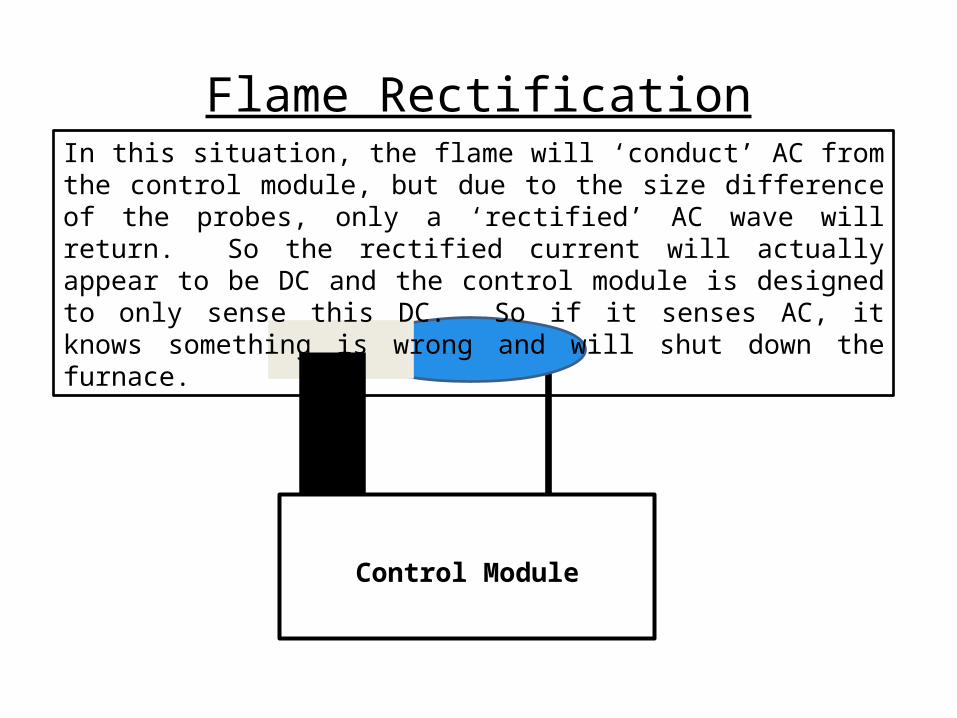
Control Module
In this situation, the flame will ‘conduct’ AC from the control module, but due to the size difference of the probes, only a ‘rectified’ AC wave will return. So the rectified current will actually appear to be DC and the control module is designed to only sense this DC. So if it senses AC, it knows something is wrong and will shut down the furnace.

Flame Rectification
Control Module
This is what the sine wave lookslike in the rectification circuit. A lot of flow in one direction, but very little flow in the opposite direction.

Now onto
Hot Surface Ignition
(HSI)
Hot Surface Ignition (HSI)
A representation of this system is found in your
Student Handout Packet, section A9.

Turn to page A9c to review the schematic,
which is shown below.

A review of the following components
found on this HSI system.
1. Main valve/Redundant valve
2. Flame Sensor Probe
3. Control Module
4. Hot Surface Ignitor

Main valve/Redundant valve
The main valve and redundant valve are actually 2
valves in one housing that are piped in series.
They both must be open for gas to flow to the
burners, but if either one does NOT open or
closes during operation, no more gas flows to the
main burners.

Main valve/Redundant valve
One valve would do the job, but because there are
two, it is considered ‘redundant.’ This feature is
for safety considerations.

Main valve/Redundant valve
Look at the schematic and notice how the two
valves are electrically connected. They are wired
in parallel. This means that both valves will get
voltage at the same time and they will open
together.

Main valve/Redundant valve
To review, the main valve and redundant valves
are PIPED in series, but WIRED in parallel.

Flame Sensor Probe
The ‘flame sensor probe’ may also be known
as the ‘flame probe’ or ‘flame rod.’ It is a
piece of stainless steel that one end is
inserted into the gas flame, and the other
end is connected to the control module.
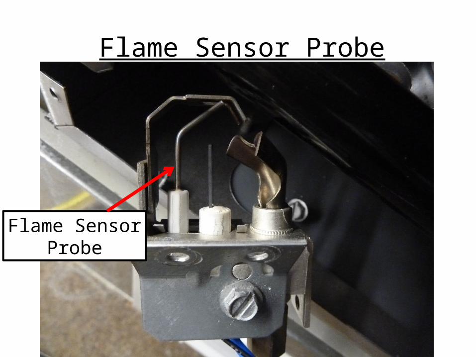
Flame Sensor Probe
Flame SensorProbe

Flame Sensor Probe
The ‘flame sensor probe’ function is to
sense the flame. More on how it does this
later.

Control Module
The ‘Control Module’ is the brains behind the
operation. It starts the sequence of
operation and will provide safety shutdown if
it detects anything is wrong either during
start-up or during the running time of the
equipment. We will go over its sequence of
operation later.
Hot Surface Ignitor
The hot surface ignitor can be either silicone
carbide or silicone nitride. When either
device receives the voltage that it is rated at,
it will get very hot and glow. This then
becomes the high tech version of the older
‘glow coil’ described in a previous
presentation.

Several Hot Surface Ignitor Configurations
SiliconeCarbide
SiliconeNitride
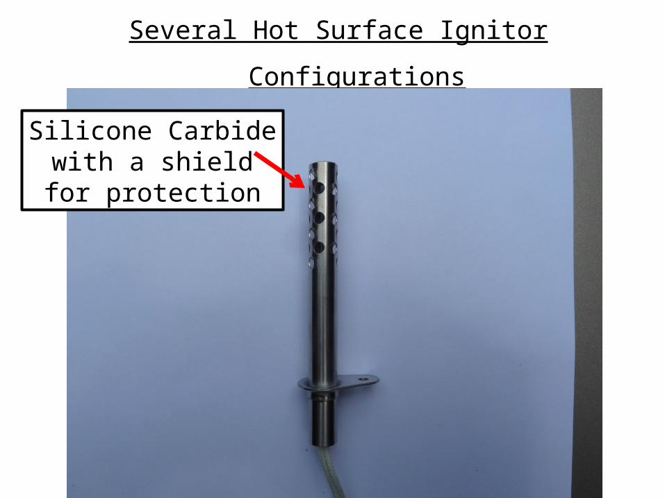
Several Hot Surface Ignitor Configurations
Silicone Carbidewith a shieldfor protection

Now that we have gone through each of the
components of an HSI system, we will go
through the sequence of operation. This
sequence is also available on page A9c of your
Student Handout Packet.

HSI Sequence of Operation

Power is supplied to the furnace

Thermostat calls for heat,control module is energized

Control module starts the ignition sequence,silicone carbide ignitor is energized and gets ‘hot.’

After approximately 17 or 45 seconds, control module energizes terminals MV and MV, both gas valves are energized and gas flows to the burners.

Flame sensor senses flame and ‘rectifies’ the current. Proof of ignition has occurred.
Flame conducts current from sensor to ground of furnace housing.

After proof of ignition has occurred,control module will de-energize HSI.

This completes the sequence of operation.
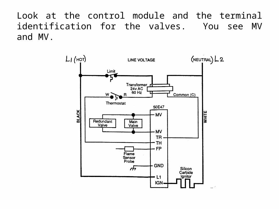
Look at the control module and the terminal identification for the valves. You see MV and MV.

MV and MV is abbreviated for Main Valve. What
you don’t see is a PV for PILOT VALVE. This
means that this control system does NOT have a
separate pilot. The main burner gas is ignited
and serves in place of the pilot gas. The control
system proves ignition for the main burners.
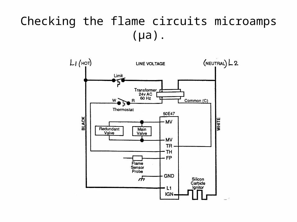
Checking the flame circuits microamps (µa).

1. Remove the flame sensor wire from the control module.
Wire removed here
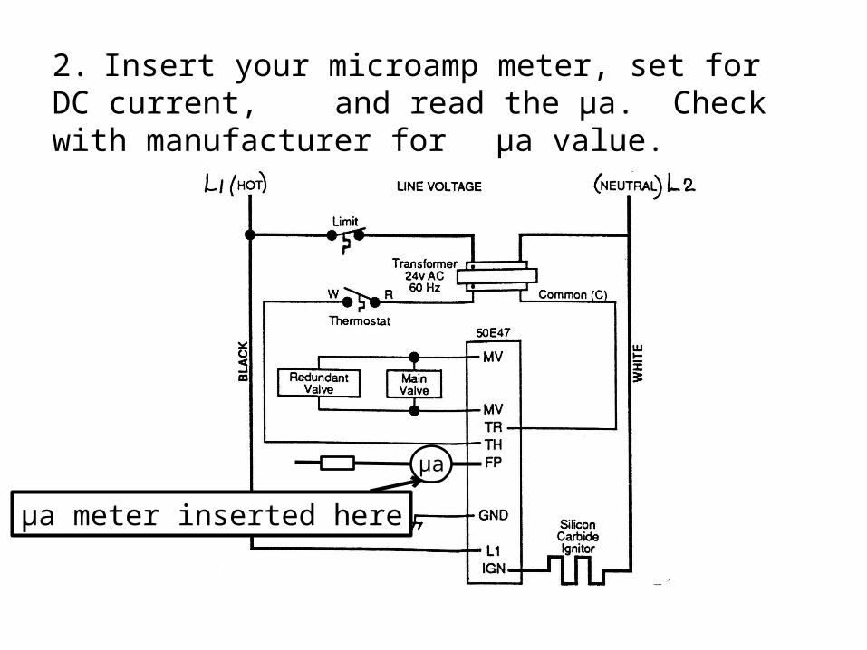
2. Insert your microamp meter, set for DC current, and read the µa. Check with manufacturer for
µa value.
aµa
µa meter inserted here

Now onto
Direct Spark Ignition
(DSI)

Direct Spark Ignition (DSI)
A representation of this system is found in your
Student Handout Packet, section A10.

Turn to page A10e to review the schematic,
which is shown below.

You should observe the following about this circuit.

1. There is NO flame sensor identified. The ‘flame
sensing loop’ is the ground (GND) wire plus the high
voltage wire used for the spark.

2. When you want to check the flame rectification
circuit, you would break the GND wire.
µa
µa meter inserted
here

3. Notice there is a ‘pilot burner.’ This means there is a
pilot that is lit before the main burners.

4. Notice there are three terminals marked: MV,
MV/PV, PV. This ignition system uses two valves in the
same housing: pilot valve and main valve.

5. The MV/PV terminal would be ‘common’ to both valves
as shown below.
MV PV

Direct Spark Ignition (DSI)
Sequence of operation
The sequence of operation and troubleshooting
this circuit may be found in the Student Handout
Packet A10 section. A brief version is found on
the next several slides.

Direct Spark Ignition (DSI)
Sequence of operation
1. Thermostat calls for heat.
2. The control module energizes the ignition
transformer so that a high intensity spark is
created at the pilot burner. The control
module, at the same time, will energize
terminals MV/PV to PV to open the pilot valve.

Direct Spark Ignition (DSI)
Sequence of operation
3. Pilot gas flows to the pilot assembly and is lit
by the spark.
4. The pilot flame will then allow current to flow
across the spark gap from the high tension
cable through the GND wire.

Direct Spark Ignition (DSI)
Sequence of operation
5. The control module will sense ‘proof’ of pilot
flame and will then energize terminals MV/PV
to MV and allow the main valve to open to the
main burners.

In conclusion, you can determine the sequence of
operation of these two systems by looking at the
schematic. If the schematic shows the control
module with MV, MV/PV and PV, then there will be
a pilot valve and a main valve. If the control
module only has MV and MV, then there is no pilot
valve.

The sequence of operation would be either:
1. light pilot, prove pilot flame, then open main
valve or
2. light main burners, prove main burner flame.
In either sequence, there is NO standing
pilot. Therefore it is a pilotless ignition
system.
This concludes the information relating to ‘Group
IV.’ Refer to your textbook for additional
information.

Miscellaneous Information
(for tests)

When troubleshooting, what are the three circuits
a technician might have to troubleshoot?
1. Power
2. Control
3. Safety

What are the first three things you do when you
arrive on the job?
1. ASK the customer what they observed.
2. Check that the system switch on the
thermostat is properly set.
3. Set the thermostat to call for MAXIMUM heat.

Continue onto the next power point
presentation in this series. Look for
the title: Fan and Limit

The End

![[-]GDG UPFLOW GAS FURNACE Form 92-21650-34-04...Title [-]GDG UPFLOW GAS FURNACE Form 92-21650-34-04 Subject: GAS FURNACE UPFLOW Keywords: GDG, GAS, UPFLOW, FURNACE, [-]GDG, 92-21650-34-04](https://img.pdfslide.us/doc/110x75/60adbca1a05ef2753c1c4a21/-gdg-upflow-gas-furnace-form-92-21650-34-04-title-gdg-upflow-gas-furnace.jpg)