Embed Size (px)
Citation preview
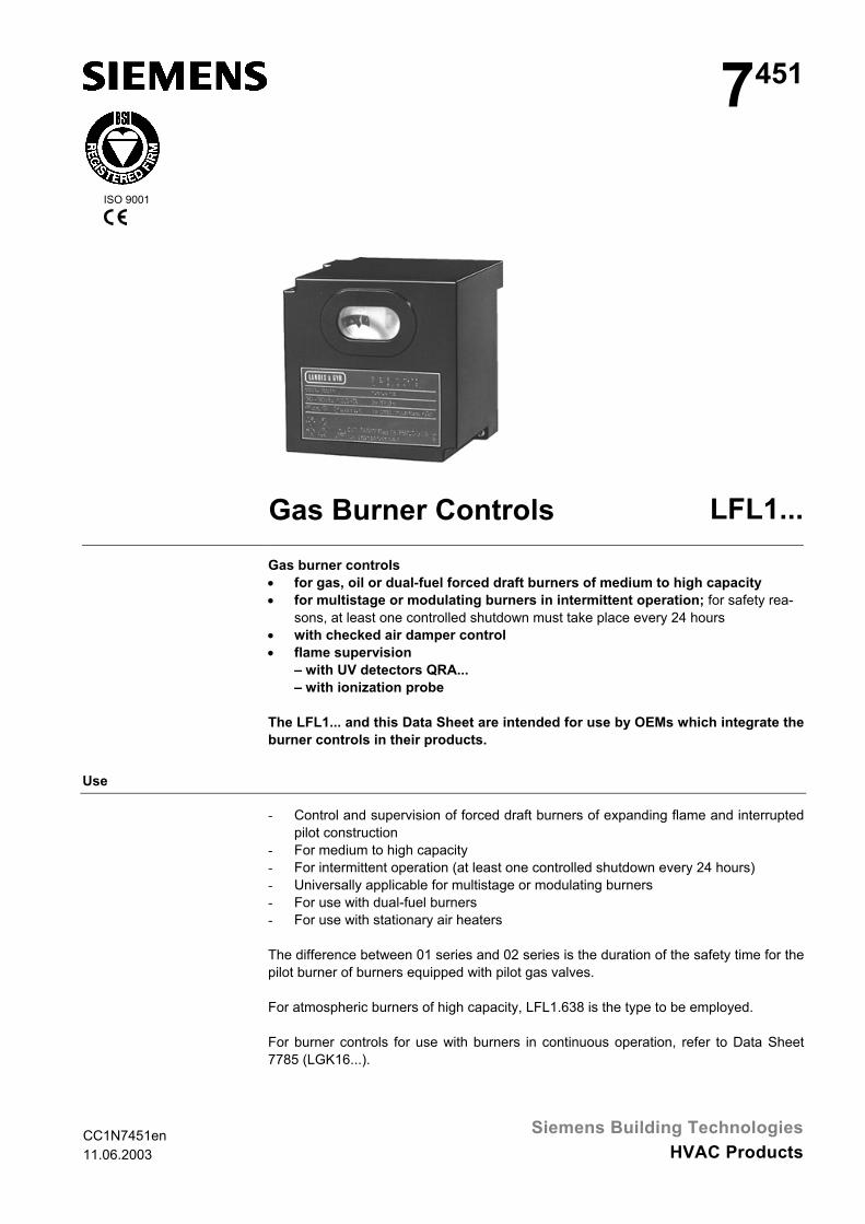
CC1N7451en11.06.2003
Siemens Building TechnologiesHVAC Products
ISO 9001
7451
Gas Burner Controls LFL1...Gas burner controls• for gas, oil or dual-fuel forced draft burners of medium to high capacity• for multistage or modulating burners in intermittent operation; for safety rea-
sons, at least one controlled shutdown must take place every 24 hours• with checked air damper control• flame supervision
– with UV detectors QRA...– with ionization probe
The LFL1... and this Data Sheet are intended for use by OEMs which integrate theburner controls in their products.
Use
- Control and supervision of forced draft burners of expanding flame and interruptedpilot construction
- For medium to high capacity- For intermittent operation (at least one controlled shutdown every 24 hours)- Universally applicable for multistage or modulating burners- For use with dual-fuel burners- For use with stationary air heaters
The difference between 01 series and 02 series is the duration of the safety time for thepilot burner of burners equipped with pilot gas valves.
For atmospheric burners of high capacity, LFL1.638 is the type to be employed.
For burner controls for use with burners in continuous operation, refer to Data Sheet7785 (LGK16...).
2/20
Siemens Building Technologies CC1N7451enHVAC Products 11.06.2003
Warning notes
To avoid injury to persons, damage to property or the environment, the followingwarning notes should be observed!
Do not open, interfere with or modify the unit!
• Before performing any wiring changes in the connection area of the LFL1…, com-pletely isolate the unit from the mains supply (all-polar disconnection)
• Ensure protection against electric shock hazard by providing adequate protectionfor the burner control’s connection terminals
• Check to ensure that wiring is in an orderly state• Press the lockout reset button only manually (apply a force of no more than 10 N),
without using any tools or pointed objects• Do not press the lockout reset button on the unit or the remote lockout reset
button for more than 10 seconds since this damages the lockout relay in theunit
• Fall or shock can adversely affect the safety functions. Such units may not be putinto operation, even if they do not exhibit any damage
• In the case of flame supervision with UV detectors QRA..., it should be noted thatsources of radiation such as halogen lamps, welding equipment, special lamps, ig-nition sparks, as well as X-rays and gamma radiation, can produce erroneousflame signals
3/20
Siemens Building Technologies CC1N7451enHVAC Products 11.06.2003
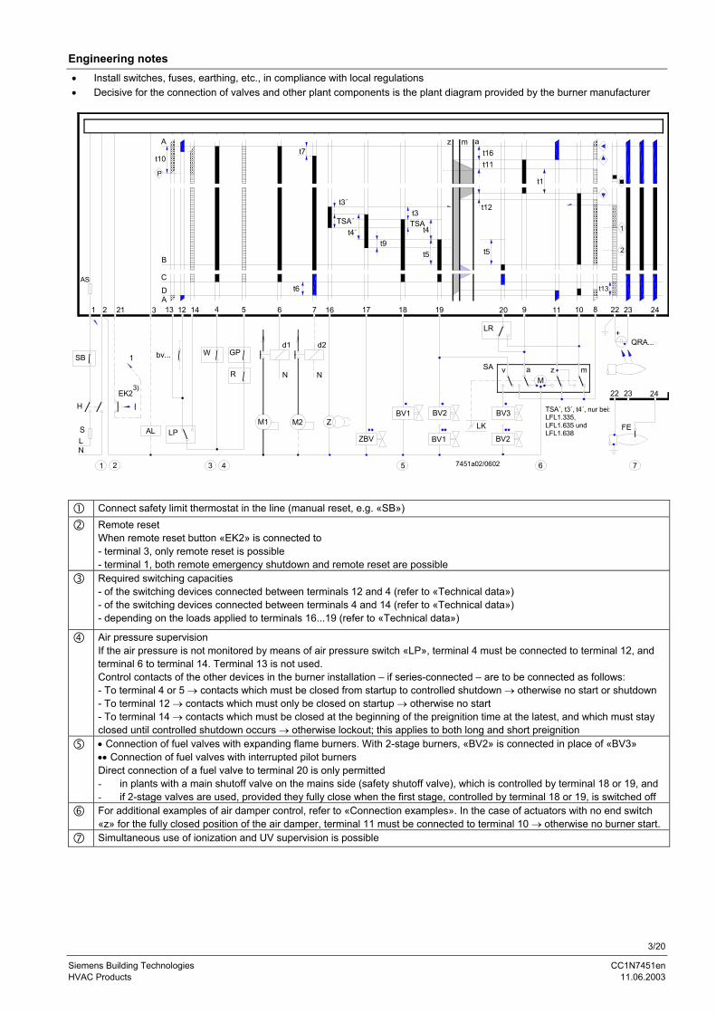
Engineering notes• Install switches, fuses, earthing, etc., in compliance with local regulations• Decisive for the connection of valves and other plant components is the plant diagram provided by the burner manufacturer
3 4 5 6 7
+
22 23 24
FE
1 2
BV2
v aM
z m
QRA...
ZBV
BV1 BV2
BV1
LK
SA
LR
BV3
R
d1
N
M1
d2
N
M2 Z
N
1
EK2
AL
bv...
LP
GPW
11 10 8 22 23 24
H
L
6 7 16 17 18 19 20 92 21 3 13 12 14 4 5
t11
t12
t5
t1
1
2
t13
1
t3TSA
t4
t5
z m at16
D
At7
t6
t3´
TSA´t4´
t9
AS
A
t10
P
B
C
3)
7451a02/0602
TSA´, t3´, t4´, nur bei:LFL1.335,LFL1.635 undLFL1.638
SB
S
Connect safety limit thermostat in the line (manual reset, e.g. «SB»)Remote resetWhen remote reset button «EK2» is connected to- terminal 3, only remote reset is possible- terminal 1, both remote emergency shutdown and remote reset are possibleRequired switching capacities- of the switching devices connected between terminals 12 and 4 (refer to «Technical data»)- of the switching devices connected between terminals 4 and 14 (refer to «Technical data»)- depending on the loads applied to terminals 16...19 (refer to «Technical data»)
Air pressure supervisionIf the air pressure is not monitored by means of air pressure switch «LP», terminal 4 must be connected to terminal 12, andterminal 6 to terminal 14. Terminal 13 is not used.Control contacts of the other devices in the burner installation – if series-connected – are to be connected as follows:- To terminal 4 or 5 → contacts which must be closed from startup to controlled shutdown → otherwise no start or shutdown- To terminal 12 → contacts which must only be closed on startup → otherwise no start- To terminal 14 → contacts which must be closed at the beginning of the preignition time at the latest, and which must stayclosed until controlled shutdown occurs → otherwise lockout; this applies to both long and short preignition• Connection of fuel valves with expanding flame burners. With 2-stage burners, «BV2» is connected in place of «BV3»•• Connection of fuel valves with interrupted pilot burnersDirect connection of a fuel valve to terminal 20 is only permitted- in plants with a main shutoff valve on the mains side (safety shutoff valve), which is controlled by terminal 18 or 19, and- if 2-stage valves are used, provided they fully close when the first stage, controlled by terminal 18 or 19, is switched offFor additional examples of air damper control, refer to «Connection examples». In the case of actuators with no end switch«z» for the fully closed position of the air damper, terminal 11 must be connected to terminal 10 → otherwise no burner start.Simultaneous use of ionization and UV supervision is possible
4/20
Siemens Building Technologies CC1N7451enHVAC Products 11.06.2003
Mounting notes
• Ensure that the relevant national safety regulations are observed• Mounting work must be carried out by qualified staff• When using 2 UV detectors QRA..., make certain that the detectors cannot see one
another
Installation notes
• Installation work must be carried out by qualified staff• Always run the high-voltage ignition cables separately while observing the greatest
possible distance to the unit and to other cables• Do not mix up live and neutral conductors
Electrical connection of ionization probe and flame detector
It is important to achieve practically disturbance- and loss-free signal transmission:• Never run the detector cable together with other cables
– Line capacitance reduces the magnitude of the flame signal– Use a separate cable of low capacitance
• Observe the maximum permissible detector cable lengths (refer to «Technicaldata»)
• 2 UV detectors QRA... can be connected in parallel• The ionization probe is not protected against electric shock hazard• Locate the ignition electrode and ionization probe such that the ignition spark can-
not arc over to the ionization probe (risk of electrical overloads)• In connection with the QRA..., earthing of terminal 22 is mandatory• Supervision with both ionization probe and UV detector QRA... is possible, but for
safety reasons – with the exception of the second safety time «t9» – only one flamedetector may be active at a time. At the end of the second safety time, one of thedetectors must be inactive, however, that is, the detected flame must have extin-guished, e.g. by switching off the ignition valve at terminal 17
Commissioning notes
• Commissioning work must be carried out by qualified staff• Prior to commissioning, check to ensure that wiring is in an orderly state• When commissioning the plant or when doing maintenance work, make the follow-
ing safety checks:
Safety check to be carried out Anticipated responsea) Burner start with flame detector dark-
enedLockout at the end of «TSA»
b) Burner start with flame detector ex-posed to extraneous light
Lockout after 40 seconds at thelatest
c) Burner operation with simulated lossof flame; for that purpose, darken theflame detector in operation and main-tain that state (not possible with ioni-zation)
Lockout
5/20
Siemens Building Technologies CC1N7451enHVAC Products 11.06.2003
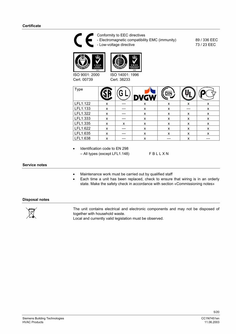
Certificate
Conformity to EEC directives- Electromagnetic compatibility EMC (immunity)- Low-voltage directive
89 / 336 EEC73 / 23 EEC
ISO 9001: 2000Cert. 00739
ISO 14001: 1996Cert. 38233
Type
LFL1.122 x --- x x x xLFL1.133 x --- x x --- xLFL1.322 x --- x x x xLFL1.333 x --- x x x xLFL1.335 x x x x x xLFL1.622 x --- x x x xLFL1.635 x --- x x x xLFL1.638 x --- x --- x ---
• Identification code to EN 298– All types (except LFL1.148) F B L L X N
Service notes
• Maintenance work must be carried out by qualified staff• Each time a unit has been replaced, check to ensure that wiring is in an orderly
state. Make the safety check in accordance with section «Commissioning notes»
Disposal notes
The unit contains electrical and electronic components and may not be disposed oftogether with household waste.Local and currently valid legislation must be observed.
6/20
Siemens Building Technologies CC1N7451enHVAC Products 11.06.2003
Mechanical design
- Plug-in design- Exchangeable unit fuse (incl. spare fuse)
- Made of impact-proof and heat-resistant black plastic- Lockout reset button with viewing window showing
– the fault signal lamp– the lockout indicator - coupled to the program spindle - visible in the transparent lockout reset button - uses easy-to-remember symbols to indicate the type of fault and the time lockout occurred
- Plug-in base and connectors of the LFL1... are designed such that only LFL1...type burner controls can be plugged in
- With 24 connection terminals- With auxiliary terminals «31» and «32»- With 3 earthing terminals, joining in a lug for earthing the burner- With 3 neutral conductor terminals
– prewired to terminal 2- With 14 knockout holes for cable entry with cable entry glands
– 8 at the side– 6 in the floor
- With 6 lateral threaded knockout holes for cable entry glands Pg11 or M16
Type summary
Switching times are given in seconds, in the burner startup sequence, valid for 50 Hz mains frequency. At 60 Hz, the switchingtimes are about 17 % shorter.
Preferred use for / in:Flash steamgenerators
Flash steamgenerators
D (incl. sta-tionary airheaters)F
AD
GB FI
BNL ²)
Large at-mosphericburners
LFL1.122 ¹)02 series
LFL1.133 ¹)02 series
LFL1.322 ¹)02 series
LFL1.333 ¹)02 series
LFL1.335 ¹)01 series
LFL1.622 ¹)02 series
LFL1.635 ¹)01 series
LFL1.638 01series
t1 10 9 36 31.5 37.5 66 67.5 67.5TSA 2 3 2 3 2.5 2 2.5 2.5TSA´ --- --- --- --- 5 --- 5 5t3 4 3 4 6 5 4 5 5t3´ --- --- --- --- 2.5 --- 2.5 2.5t4 6 6 10 12 12.5 10 12.5 12.5t4´ --- --- --- --- 15 --- 15 15t5 4 3 10 12 12.5 10 12.5 12.5t6 10 14.5 12 18 15 12 15 15t7 2 3 2 3 2.5 2 2.5 2.5t8 30 29 60 72 78 96 105 105t9 2 3 2 3 5 2 5 7.5t10 6 6 8 12 10 8 10 10t11 Optionalt12 Optionalt13 10 14,5 12 18 15 12 15 15t16 4 3 4 6 5 4 5 5t20 32 60 --- 27 22.5 --- --- ---
¹) Available as AC 100...110 V versions; add type suffix – 110 V when ordering²) Reversed polarity protection conforming to Dutch installation standard: AGM30
Gas burner control
Housing
Plug-in base
7/20
Siemens Building Technologies CC1N7451enHVAC Products 11.06.2003
Ordering
When ordering, please give type reference according to «Type summary».
Accessories
Plug-in bases- With Pg11 threads for cable entry glands AGM410490550- With M16 threads for cable entry glands AGM14.1
Technical dataMains voltage AC 230 V –15 / +10 %
AC 100 V –15 %...AC 110 V +10 %Mains frequency 50...60 Hz ±6 %Unit fuse (built-in) T6,3H250V to DIN EN 60 127Primary fuse (external) max. 10 A (slow)Weight- LFL1...- Plug-in base
approx. 1,000 gapprox. 165 g
Flame detectors- QRA...- Ionization probe
refer to Data Sheet 7712to be supplied by thirds
Power consumption approx. AC 3.5 VAMounting position optionalDegree of protection IP 40, with the exception of the connection
areaPerm. input current at terminal 1 max. 5 A continuously, peaks up to 20 A for
20 msPerm. load on control terminals 3, 6, 7,
9...11, 15...20max. 4 A continuously, peaks up to 20 A for
max. 20 ms, total max. 5 ARequired switching capacity of switching
devices- Between terminals 4 and 5- Between terminals 4 and 12- Between terminals 4 and 14
1 A, AC 250 V1 A, AC 250 Vmin. 1 A, AC 250 Vdepending on the load on terminals 16...19
Degree of protection IP 00Cable connection (stranded wires requireferrules)
screw terminals for min. 0.5 mm² and max.1.5 mm² cross-sectional area
Ferrules suited for the respective cross-sectionalarea
Transport DIN EN 60721-3-2Climatic conditions class 2K2Mechanical conditions class 2M2Temperature range -50...+70 °CHumidity < 95 % r.h.Operation DIN EN 60 721-3-3Climatic conditions class 3K5Mechanical conditions class 3M2Temperature range -20...+60 °CHumidity < 95 % r.h.
Condensation, formation of ice and ingress of water are not permitted!
General unit dataLFL1...
Plug-in base AGM...
Environmentalconditions
8/20
Siemens Building Technologies CC1N7451enHVAC Products 11.06.2003
Voltage at the ionization probe- Operation- Test
AC 330 V ±10 %AC 380 V ±10 %
Short-circuit current max. 0.5 mARequired ionization current min. 6 µARecommended range of measuring instrument
0...50 µA
Perm. length of detector cable- Normal cable, laid separately ²)- Shielded cable
max. 80 mmax. 140 m (e.g. high-frequency cable;
shield connected to terminal 22)
Supply voltage- Operation- Test
AC 330 V ±10 %AC 380 V ±10 %
Required detector current min. 70 µAPossible detector current- Operation- Test
max. 680 µAmax. 1000 µA ¹)
Perm. length of detector cable- Normal cable, laid separately ²)- Shielded cable
max. 100 mmax. 200 m (e.g. high-frequency cable;
shield connected to terminal 22)
¹) During the prepurge time with higher test voltage: Self-ignition and extraneous light test²) Multicore cable not permitted
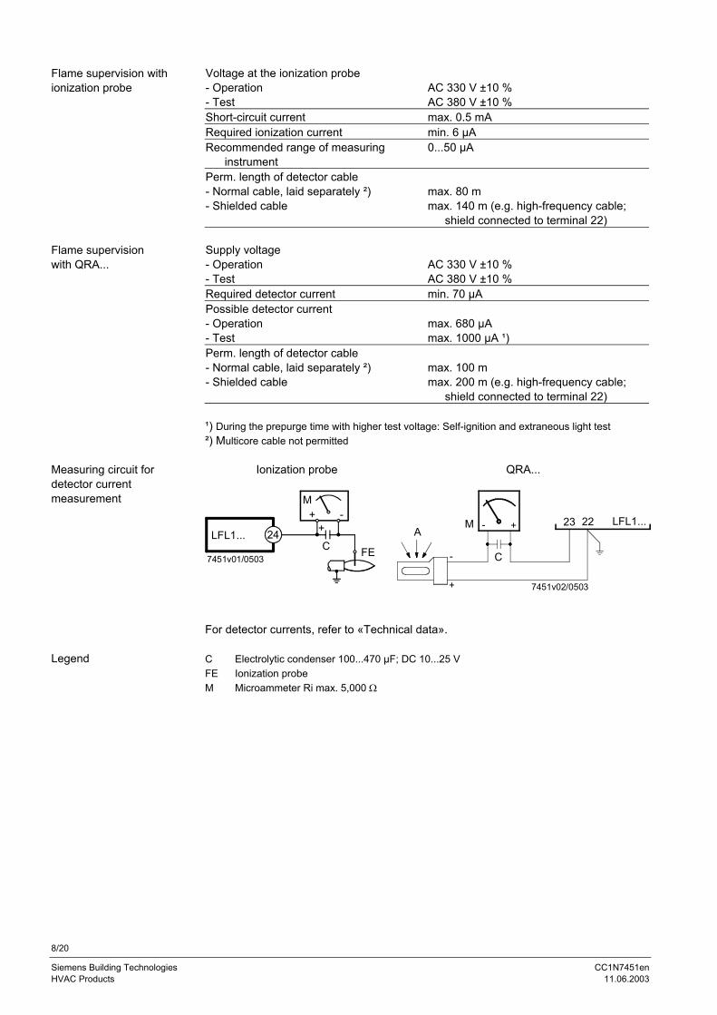
Ionization probe QRA...
LFL1... 24
7451v01/0503
M
C+
+ -
FE
7451v02/0503
AM
C
23 22 LFL1...-
+
-
+
For detector currents, refer to «Technical data».
C Electrolytic condenser 100...470 µF; DC 10...25 VFE Ionization probeM Microammeter Ri max. 5,000 Ω
Flame supervision withionization probe
Flame supervisionwith QRA...
Measuring circuit fordetector currentmeasurement
Legend
9/20
Siemens Building Technologies CC1N7451enHVAC Products 11.06.2003
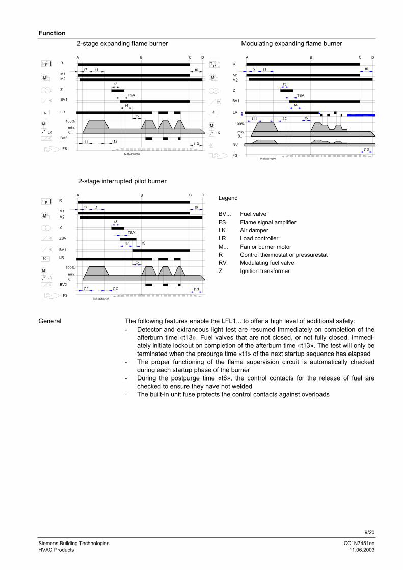
Function2-stage expanding flame burner Modulating expanding flame burner
min.0...
100%
R
M1M2
Z
BV1
LR
BV2
FS
A B C D
7451a06/0600
T P
M
R
M
LK
~
t7 t1 t6
t3
TSA
t4
t5
t11 t12 t13
R LRt5t11 t12
t13FS
min.LK0...
M 100%
RV
A
BV1
M2
Z
~M
P R
M1
T
t4
t3
t7 t1
TSA
B
t6
C D
7451a07/0600
2-stage interrupted pilot burner
FS
BV2
min.LK 0...
M
R
100%
LR
ZBV
M1M2
Z
~M
P RT
t12
t4´
t5
A B C D
t11 t13
t6t7 t1
t3´
TSA´
7451a08/0202
t9
BV1
Legend
BV... Fuel valveFS Flame signal amplifierLK Air damperLR Load controllerM... Fan or burner motorR Control thermostat or pressurestatRV Modulating fuel valveZ Ignition transformer
The following features enable the LFL1... to offer a high level of additional safety:- Detector and extraneous light test are resumed immediately on completion of the
afterburn time «t13». Fuel valves that are not closed, or not fully closed, immedi-ately initiate lockout on completion of the afterburn time «t13». The test will only beterminated when the prepurge time «t1» of the next startup sequence has elapsed
- The proper functioning of the flame supervision circuit is automatically checkedduring each startup phase of the burner
- During the postpurge time «t6», the control contacts for the release of fuel arechecked to ensure they have not welded
- The built-in unit fuse protects the control contacts against overloads
General
10/20
Siemens Building Technologies CC1N7451enHVAC Products 11.06.2003
- Burner operation with or without postpurging- Fan motors with a current draw of up to 4 A can be connected directly → starting
current max. 20 A (max. 20 ms)- Separate control outputs for
- one pilot valve, which will be shut on completion of the second safety time- Separate control outputs for the actuator’s positioning directions OPEN, CLOSE
and MIN- Checked air damper control to ensure prepurging with the nominal amount of air- Checked positions:
- CLOSED or MIN on startup → low-fire position- OPEN at the start of prepurging- MIN on completion of prepurgingIf the actuator does not drive the air damper to the required position, the burnerstartup sequence will be stopped
- 2 control outputs for the release of the second and third output stage, or load con-trol
- When load control is enabled, the control outputs for the actuator will galvanicallybe separated from the unit’s control section
- Connection facilities for- remote lockout warning device- remote reset- remote emergency shutdown
- With burner controls of the 01 series and expanding flame burners, the safety timecan be increased from 2.5 to 5 seconds by changing the circuitry (refer to «Con-nection examples»), provided the longer safety time conforms to local safety regu-lations
- With the ionization probe, in networks with earthed or nonearthed neutral conduc-tor. For this kind of supervision, the flame supervision circuit is designed such thatpossible disturbances of the ionization current due to the ignition spark normallyhave no impact on the establishment of the flame signal. A short-circuit betweenionization probe and burner ground cannot simulate a flame signal
- With UV detector QRA... (gas and oil burners)- Simultaneous use of ionization probe and QRA... (e.g. with interrupted pilot burners
or gas-electrically ignited oil burners)
- If, on startup, the required input signals are not present, the burner control inter-rupts the startup sequence at the points marked by symbols and initiates lockoutwhere required by safety regulations. The symbols used in this Data Sheet corre-spond to those on the burner control’s lockout indicator.
- Burner control must be reset- Sequence switch must be in its start position
→ voltage at terminals 4 and 11 presentAir damper closed
- End switch «z» for the CLOSED position must feed voltage from terminal 11 toterminal 8
- The contacts of control thermostat or pressurestat «W» and other contacts ofswitching devices connected between terminal 12 and «LP» must be closed → e.g.control contact for the oil preheater’s temperature
- Terminal 4 must be live- The N.C. contact of the air pressure switch must be closed → «LP» test
Control of the burner
Flame supervision
Preconditionsfor startup
Preconditions forburner startup
11/20
Siemens Building Technologies CC1N7451enHVAC Products 11.06.2003
Startup sequenceA Start command (delivered by «R» for instance)A-B Startup sequenceB Operating position of the burnerB-C Burner operation (according to the control commands delivered by «R»)C Controlled shutdown via «R»C-D Sequence switch travels to start position «A», postpurging
During burner off periods, only control outputs 11 and 12 carry voltage and theair damper is in its CLOSED position as defined by end switch «z» of the ac-tuator. Also, in order to perform the detector and extraneous light test, the flamesupervision circuit is live (terminals 22 / 23 and 22 / 24)
A Start command delivered by «R»→ «R» closes the start control loop between terminals 4 and 5- The sequence switch starts running
- Only prepurging, power is immediately fed to the fan motor connected to terminal 6 - Pre- and postpurging; on completion of «t7», power is fed to the fan mo-tor or flue gas fan connected to terminal 7
- On completion of «t16», the control command to open the air damper isdelivered via terminal 9
- No power is fed to terminal 8 during the positioning time- The sequence switch continues its travel only after the air damper has fully
opened
t1 Prepurge time with air damper fully open- During «t1», the correct functioning of the flame supervision circuit is tested- If test is not successful, the burner control will initiate lockout
Shortly after the start of «t1», the air pressure switch must change over fromterminal 13 to terminal 14.→ Otherwise lockout→ Start of air pressure check
At the same time, terminal 14 must be live since the ignition transformer will bepowered and the fuel released via this current path.
On completion of the prepurge time, the burner control will drive the air damperto the low-fire position via terminal 10, which is determined by the changeoverpoint of auxiliary switch «m». During the positioning time, the sequence switchstops again. A short time later, the motor of the sequence switch will beswitched to the control section of the burner control. This means that, from nowon, positioning signals delivered to terminal 8 have no impact on the burner’sfurther startup sequence (and on subsequent burner operation):
t5 Interval- On completion of «t5», power is fed to terminal 20; at the same time, con-
trol outputs 9...11 and input 8 are galvanically separated from the unit’scontrol section→ The LFL1... is now protected against return voltages from the power control loop
- The startup sequence of the LFL1… ends with the release of «LR» at ter-minal 20
- After a number of idle steps (steps with no change of the contact position),the sequence switch switches itself off
Sequence
12/20
Siemens Building Technologies CC1N7451enHVAC Products 11.06.2003
TSA Ignition safety timeOn completion of «TSA», a flame signal must be present at terminal 22. It mustnot be interrupted until controlled shutdown takes place → otherwise lockout
t3 Preignition timeRelease of fuel via terminal 18
t4 Interval «BV1 – BV2» or «BV1 - LR»- On completion of «t4», terminal 19 is live- That powers «BV2» connected to the actuator’s auxiliary switch «v»
t3t3´
Preignition timeRelease of fuel for pilot burner via terminal 17
TSATSA´
Ignition safety timeOn completion of «TSA», a flame signal must be present at terminal 22. It mustnot be interrupted until controlled shutdown takes place → otherwise lockout
t4t4´
Interval «ZBV-BV1»Up to the release of the fuel valve at terminal 19 for the main burner’s start load
t9 Second safety timeOn completion of the second safety time, the main burner must have been ig-nited by the pilot burner since terminal 17 becomes dead as soon as this timehas elapsed, causing the pilot valve to close
B Operating position of the burner
B-C Burner operation- During burner operation, «LR» drives the air damper to the high-fire or low-
fire position, depending on the demand for heat- Release of high-fire is enabled by auxiliary switch «v» in the actuator- In the event of loss of flame during operation, the LFL1… will initiate lockout
C Controlled shutdownOn controlled shutdown, the «BV...» will immediately be closed. At the sametime, the sequence switch starts and programs «t6»
C-D The sequence switch travels to start position «A»
t6 Postpurge time- Fan «M2» connected to terminal 7- Shortly after the start of «t6», power is fed to terminal 10
→ air damper will be driven to the MIN position- Full closing of the air damper starts only shortly before «t6» has elapsed
→ triggered by the control signal at terminal 11- During the following burner off period, terminal 11 remains live
t13 Permissible afterburn timeDuring «t13», the flame signal input can still receive a flame signal→ no lockout
Expanding flameburners
Interrupted pilotburners
13/20
Siemens Building Technologies CC1N7451enHVAC Products 11.06.2003
D-A End of control sequence→ start positionAs soon as the sequence switch has reached the start position – therebyswitching itself off – the flame detector and extraneous light test will start again.During the burner off periods, the flame supervision circuit is live.A faulty flame signal of a few seconds will initiate lockout.Short ignition pulses of the UV tube, caused for instance by cosmic radiation, donot lead to lockout.
Times «TSA´», «t3´» and «t4´» only exist with burner controls of the 01 series.
14/20
Siemens Building Technologies CC1N7451enHVAC Products 11.06.2003
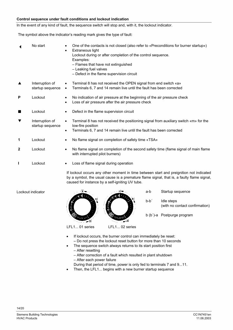
Control sequence under fault conditions and lockout indicationIn the event of any kind of fault, the sequence switch will stop and, with it, the lockout indicator.
The symbol above the indicator’s reading mark gives the type of fault:
• One of the contacts is not closed (also refer to «Preconditions for burner startup»)No start• Extraneous light
Lockout during or after completion of the control sequence.Examples:– Flames that have not extinguished– Leaking fuel valves– Defect in the flame supervision circuit
• Terminal 8 has not received the OPEN signal from end switch «a»= Interruption ofstartup sequence • Terminals 6, 7 and 14 remain live until the fault has been corrected
• No indication of air pressure at the beginning of the air pressure checkP Lockout• Loss of air pressure after the air pressure check
Lockout • Defect in the flame supervision circuit
• Terminal 8 has not received the positioning signal from auxiliary switch «m» for thelow-fire position
> Interruption ofstartup sequence
• Terminals 6, 7 and 14 remain live until the fault has been corrected
1 Lockout • No flame signal on completion of safety time «TSA»
2 Lockout • No flame signal on completion of the second safety time (flame signal of main flamewith interrupted pilot burners)
I Lockout • Loss of flame signal during operation
If lockout occurs any other moment in time between start and preignition not indicatedby a symbol, the usual cause is a premature flame signal, that is, a faulty flame signal,caused for instance by a self-igniting UV tube.
a-b Startup sequence
b-b´ Idle steps(with no contact confirmation)
b (b´)-a Postpurge program
LFL1... 01 series LFL1... 02 series
• If lockout occurs, the burner control can immediately be reset:– Do not press the lockout reset button for more than 10 seconds
• The sequence switch always returns to its start position first– After resetting– After correction of a fault which resulted in plant shutdown– After each power failureDuring that period of time, power is only fed to terminals 7 and 9...11.
• Then, the LFL1... begins with a new burner startup sequence
Lockout indicator
15/20
Siemens Building Technologies CC1N7451enHVAC Products 11.06.2003
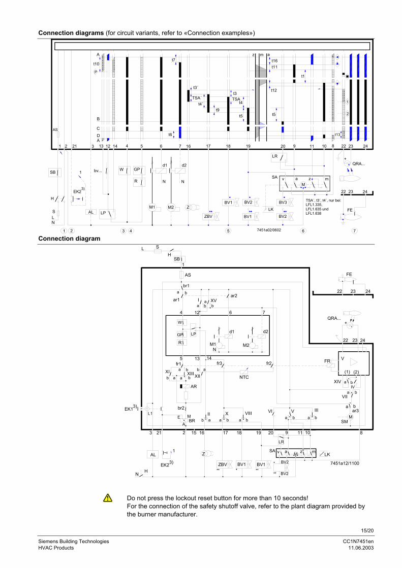
Connection diagrams (for circuit variants, refer to «Connection examples»)
3 4 5 6 7
+
22 23 24
FE
1 2
BV2
v aM
z m
QRA...
ZBV
BV1 BV2
BV1
LK
SA
LR
BV3
R
d1
N
M1
d2
N
M2 Z
N
1
EK2
AL
bv...
LP
GPW
11 10 8 22 23 24
H
L
6 7 16 17 18 19 20 92 21 3 13 12 14 4 5
t11
t12
t5
t1
1
2
t13
1
t3TSA
t4
t5
z m at16
D
At7
t6
t3´
TSA´t4´
t9
AS
A
t10
P
B
C
3)
7451a02/0602
TSA´, t3´, t4´, nur bei:LFL1.335,LFL1.635 undLFL1.638
SB
S
Connection diagram
1
AS
br1
ar1 I XVar2
FE
22 23 24
76124
R
LP
5 13 14
NM1 M2
d1 d2
22 23 24
QRA...
fr1XI XIII XII
AR
br2L1
EK1
BR
3 21 2 16
AL
NH
EK2
1
17 19
Z
ZBV BV1
20 9 11 8
LKSA a z mM
EA
M
ab b
a
a b b a
a b
baa
b
fr3
NTC
fr2 FR V
(1) (2)
a bXIVIV
XIIb ba
a
7451a12/1100
3)
15
VIIIba
18
VVIba
IIIba
baar3
baVII
10
MSM
GP
v
3) BV1
BV2
BV2
LR
+
SB
LH
W
S
Do not press the lockout reset button for more than 10 seconds!For the connection of the safety shutoff valve, refer to the plant diagram provided bythe burner manufacturer.
16/20
Siemens Building Technologies CC1N7451enHVAC Products 11.06.2003
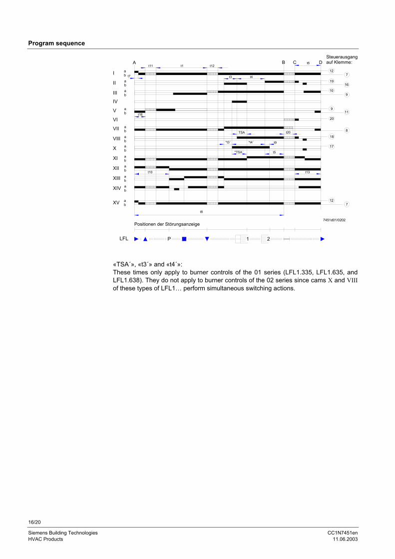
Program sequence
At11
t7
t1 t12B C Dt6
t20
t13t10
t16
t8
Positionen der Störungsanzeige
Steuerausgangauf Klemme:
P
20
7
19
8
9
910
I
II
III
IV
V
VI
VII
VIII
X
XI
XII
XIII
XIV
ababab
ab
ababab
abab
abab
7451d01/0202
12
16
11
17
18
7XV ab
12
t3 t4
*t3´ *t4´ t9
TSA
*TSA´ t5
1 2LFL
«TSA´», «t3´» and «t4´»:These times only apply to burner controls of the 01 series (LFL1.335, LFL1.635, andLFL1.638). They do not apply to burner controls of the 02 series since cams X and VIIIof these types of LFL1… perform simultaneous switching actions.
17/20
Siemens Building Technologies CC1N7451enHVAC Products 11.06.2003
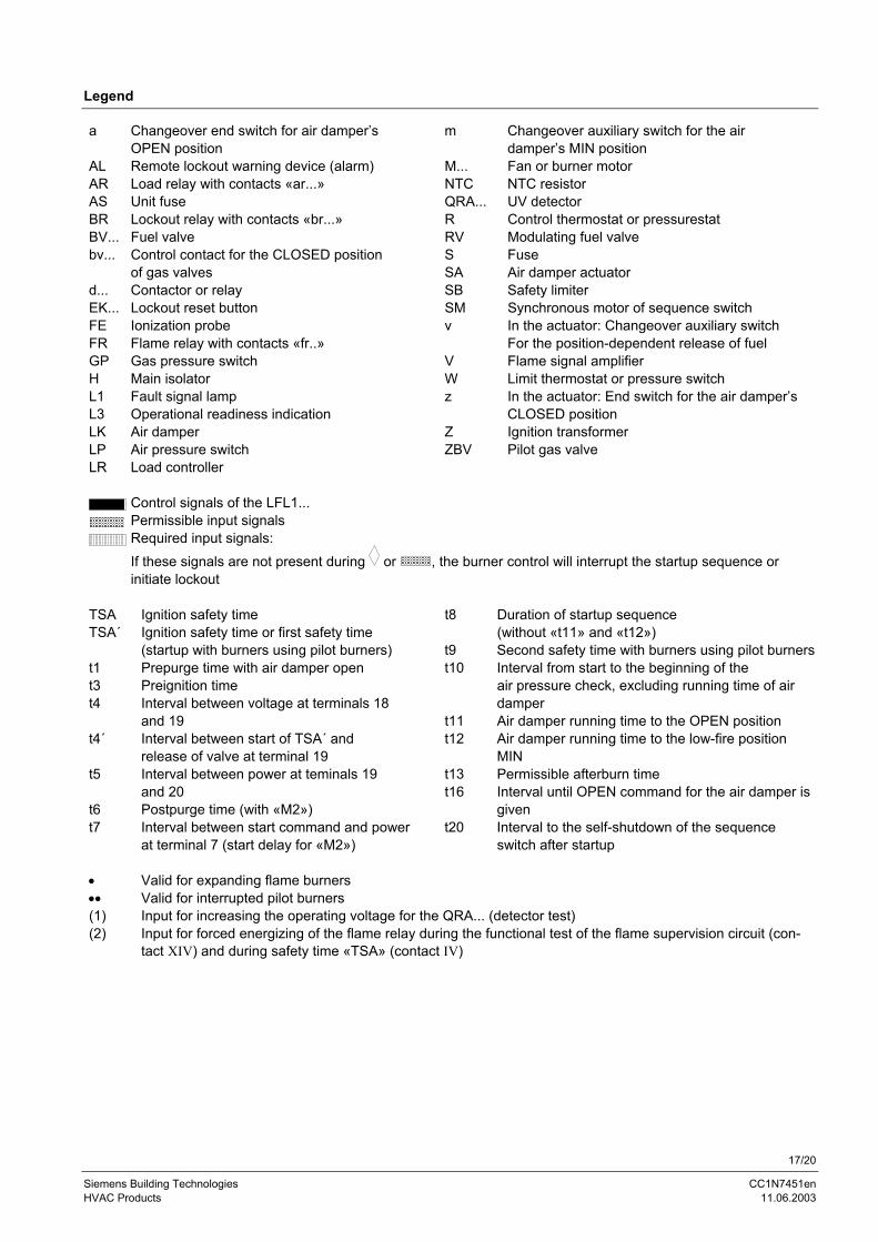
Legend
a Changeover end switch for air damper’s m Changeover auxiliary switch for the airOPEN position damper’s MIN position
AL Remote lockout warning device (alarm) M... Fan or burner motorAR Load relay with contacts «ar...» NTC NTC resistorAS Unit fuse QRA... UV detectorBR Lockout relay with contacts «br...» R Control thermostat or pressurestatBV... Fuel valve RV Modulating fuel valvebv... Control contact for the CLOSED position S Fuse
of gas valves SA Air damper actuatord... Contactor or relay SB Safety limiterEK... Lockout reset button SM Synchronous motor of sequence switchFE Ionization probe v In the actuator: Changeover auxiliary switchFR Flame relay with contacts «fr..» For the position-dependent release of fuelGP Gas pressure switch V Flame signal amplifierH Main isolator W Limit thermostat or pressure switchL1 Fault signal lamp z In the actuator: End switch for the air damper’sL3 Operational readiness indication CLOSED positionLK Air damper Z Ignition transformerLP Air pressure switch ZBV Pilot gas valveLR Load controller
Control signals of the LFL1...Permissible input signalsRequired input signals:If these signals are not present during or , the burner control will interrupt the startup sequence orinitiate lockout
TSA Ignition safety time t8 Duration of startup sequenceTSA´ Ignition safety time or first safety time (without «t11» and «t12»)
(startup with burners using pilot burners) t9 Second safety time with burners using pilot burnerst1 Prepurge time with air damper open t10 Interval from start to the beginning of thet3 Preignition time air pressure check, excluding running time of airt4 Interval between voltage at terminals 18 damper
and 19 t11 Air damper running time to the OPEN positiont4´ Interval between start of TSA´ and t12 Air damper running time to the low-fire position
release of valve at terminal 19 MINt5 Interval between power at teminals 19 t13 Permissible afterburn time
and 20 t16 Interval until OPEN command for the air damper ist6 Postpurge time (with «M2») givent7 Interval between start command and power t20 Interval to the self-shutdown of the sequence
at terminal 7 (start delay for «M2») switch after startup
• Valid for expanding flame burners•• Valid for interrupted pilot burners(1) Input for increasing the operating voltage for the QRA... (detector test)(2) Input for forced energizing of the flame relay during the functional test of the flame supervision circuit (con-
tact XIV) and during safety time «TSA» (contact IV)
18/20
Siemens Building Technologies CC1N7451enHVAC Products 11.06.2003
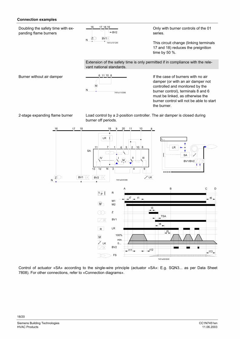
Connection examples
Doubling the safety time with ex-panding flame burners
16
ZN
17 18
BV1
19
BV2
7451a10/1295
Only with burner controls of the 01series.
This circuit change (linking terminals17 and 18) reduces the preignitiontime by 50 %.
Extension of the safety time is only permitted if in compliance with the rele-vant national standards.
Burner without air damper 11 10 86
7451a11/0396
MN
If the case of burners with no airdamper (or with an air damper notcontrolled and monitored by theburner control), terminals 8 and 6must be linked, as otherwise theburner control will not be able to startthe burner.
2-stage expanding flame burner Load control by a 2-position controller. The air damper is closed duringburner off periods.
16
ZN
17 18
BV1 BV2
SA
LR
19 9 20 11 10 8
LK
11 7 1 6 5 2 10 8
943N1213
IV IM
II III
7451a03/0396
L...
LR
SA
BV1/BV2
min.0...
100%
R
M1M2
Z
BV1
LR
BV2
FS
A B C D
7451a06/0600
T P
M
R
M
LK
~
t7 t1 t6
t3
TSA
t4
t5
t11 t12 t13
Control of actuator «SA» according to the single-wire principle (actuator «SA»: E.g. SQN3... as per Data Sheet7808). For other connections, refer to «Connection diagrams».
19/20
Siemens Building Technologies CC1N7451enHVAC Products 11.06.2003
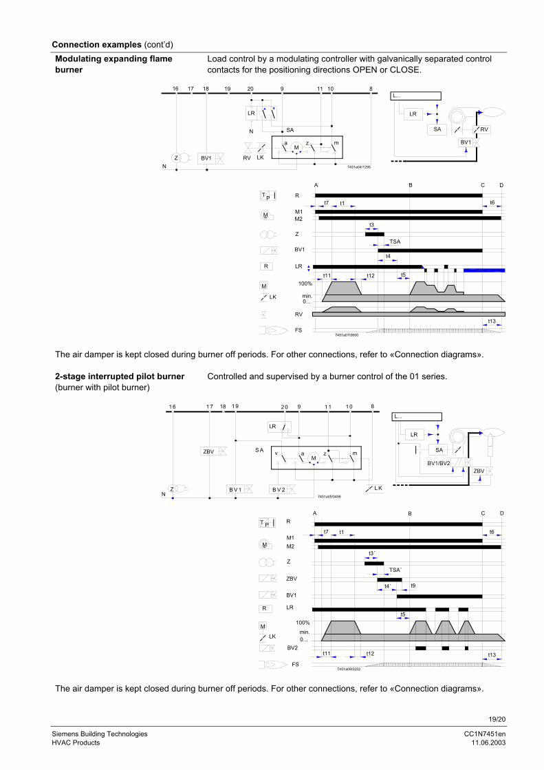
Connection examples (cont’d)Modulating expanding flameburner
Load control by a modulating controller with galvanically separated controlcontacts for the positioning directions OPEN or CLOSE.
16 820
LR
N
9 11
M
10
ZN
17 18 19
RV LK
SA
a mz
BV17451a04/1295
L...
LR
SA
BV1
RV
R LRt5t11 t12
t13FS
min.LK0...
M 100%
RV
A
BV1
M2
Z
~M
P R
M1
T
t4
t3
t7 t1
TSA
B
t6
C D
7451a07/0600
The air damper is kept closed during burner off periods. For other connections, refer to «Connection diagrams».
2-stage interrupted pilot burner(burner with pilot burner)
Controlled and supervised by a burner control of the 01 series.
N
S A
Z B V 1 B V 2
LR
L K
2 01 6 1 7 1 9 9 1 1 1 0 8
7451a05/0496
LR
SA
L...
ZBV
Ma mzv
BV1/BV2
ZBV
18
FS
BV2
min.LK 0...
M
R
100%
LR
ZBV
M1M2
Z
~M
P RT
t12
t4´
t5
A B C D
t11 t13
t6t7 t1
t3´
TSA´
7451a08/0202
t9
BV1
The air damper is kept closed during burner off periods. For other connections, refer to «Connection diagrams».
20/20
Siemens Building Technologies CC1N7451enHVAC Products 11.06.2003
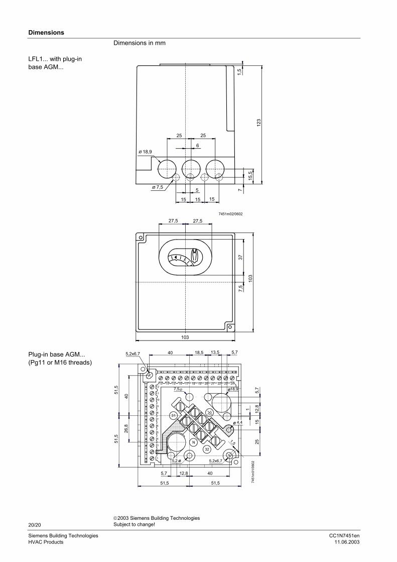
DimensionsDimensions in mm
1,5
123
7
15,5
618,9
25 25
7,5 5
15 15 15
27,5 27,5
377,
5
103
103
7451m02/0602
5,2x6,7 40 18,5 13,5 5,7
51,5
4026
,8
51,5
5,7 12,8
51,5
40
51,5
2515
1 12,8
5,77,5 18,9
4,4
1,5
5,2x6,75,2
7451
m01
/060
2
31
32
N
1
2
3
4
5
6
7
8
9
10
11
1213 14 15 16 17 18 19 20 21 22 23 24
LFL1... with plug-inbase AGM...
Plug-in base AGM...(Pg11 or M16 threads)
2003 Siemens Building TechnologiesSubject to change!