Embed Size (px)
Citation preview
Galileo & DE2i-150 Interface: Photocell Circuit
Team Alpha Centauri:Phathom Donald
Alexis Wells4.7.14
EECE494: Computer Bus and SoC InterfacingDepartment of Electrical and Computer Engineering
Howard UniversityInstructor: Dr. Charles Kim
Idea Formation
Simulation of a monitoring device that shows
the state of photocell as low or high.
Accomplished through interface of Galileo
board & DE2i-150 board, using GPIO expansion
of DE2i-150 board.
2
Introduction
• A message, determined by the Galileo board, will
appear on the DE2i-150, notifying the user if a
photocell is detecting light or not.
• The photocell is detecting light if the message
reads High.
• The photocell is not detecting light if the
message reads Low.
3
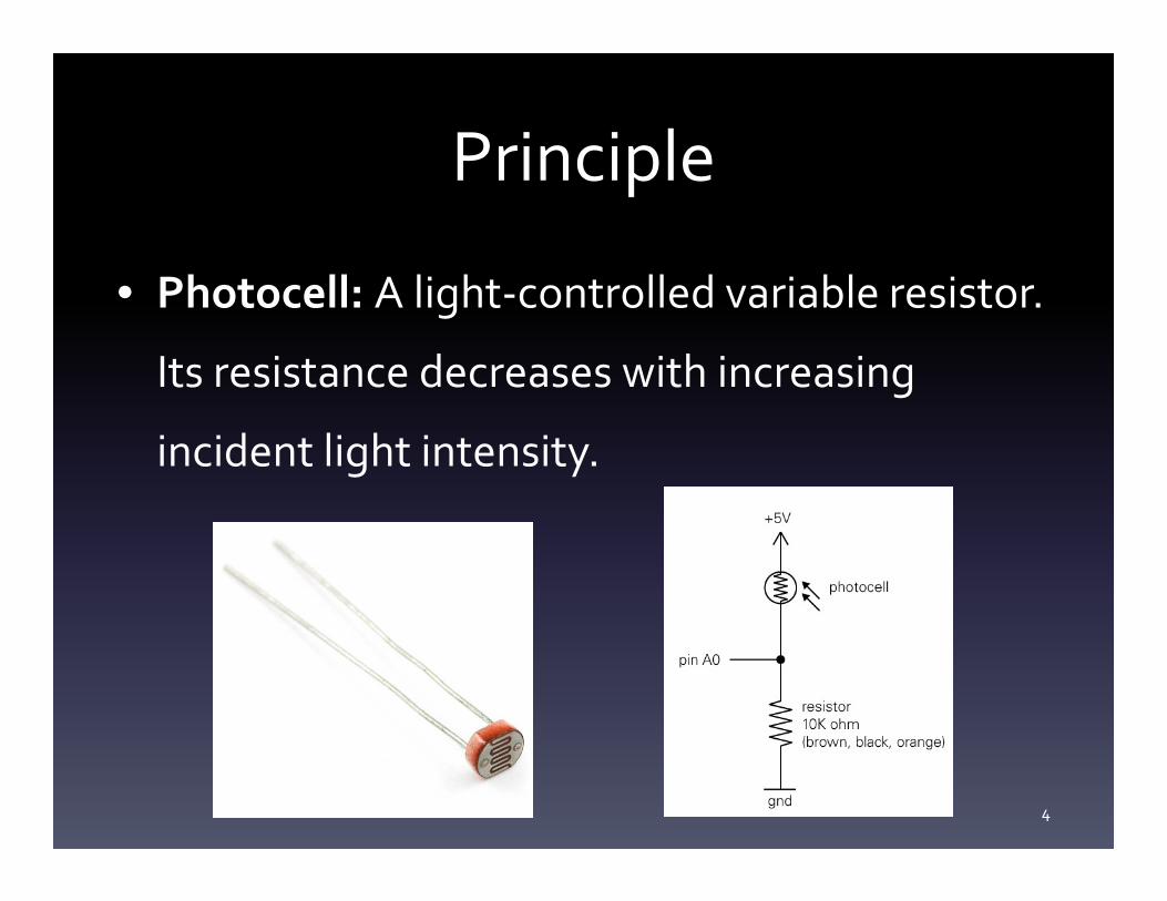
Principle
• Photocell: A light-controlled variable resistor.
Its resistance decreases with increasing
incident light intensity.
4
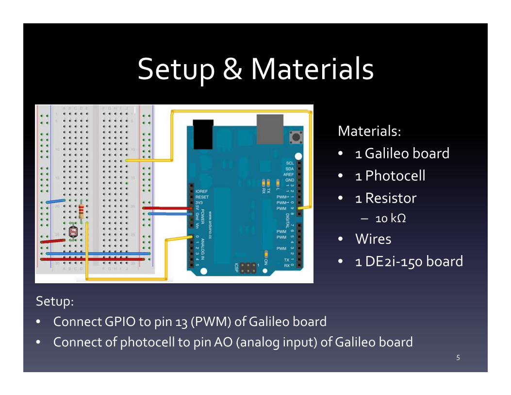
Setup & Materials
Materials:• 1 Galileo board• 1 Photocell• 1 Resistor
– 10 kΩ
• Wires• 1 DE2i-150 board
Setup:• Connect GPIO to pin 13 (PWM) of Galileo board• Connect of photocell to pin AO (analog input) of Galileo board
5
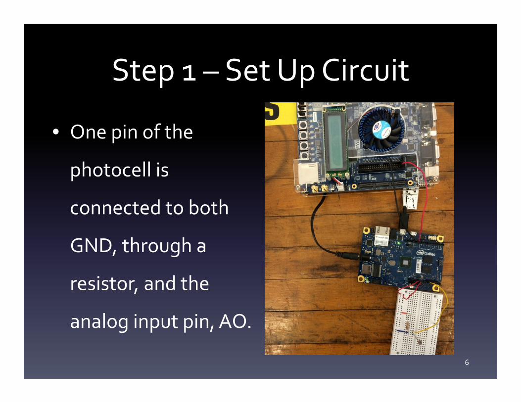
Step 1 – Set Up Circuit
• One pin of the
photocell is
connected to both
GND, through a
resistor, and the
analog input pin, AO.
6
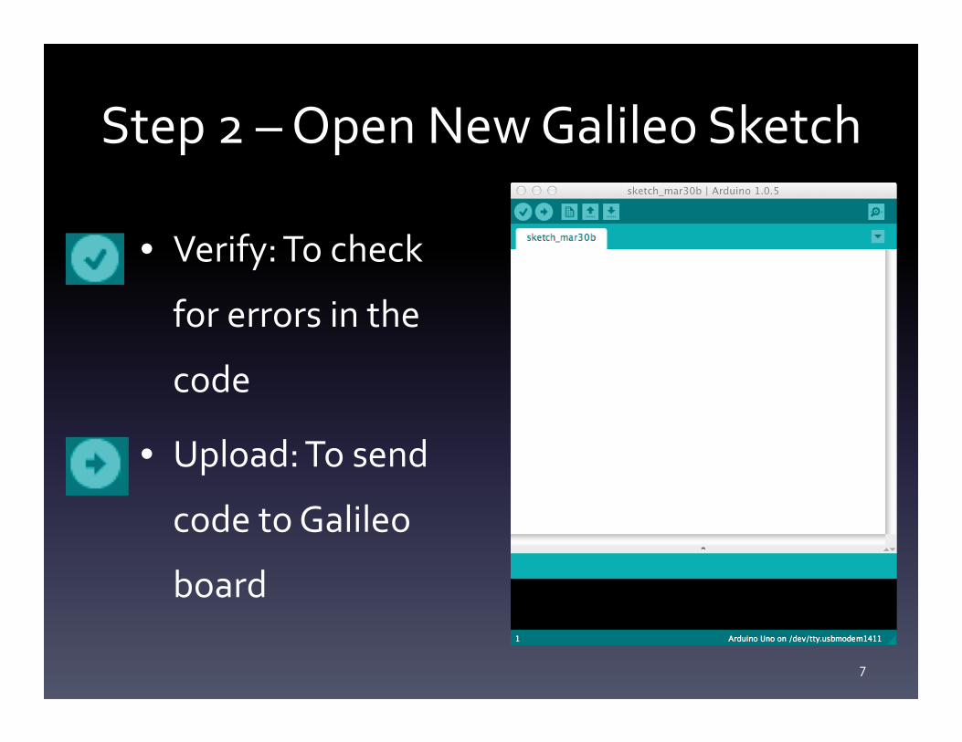
Step 2 – Open New Galileo Sketch
• Verify: To check
for errors in the
code
• Upload: To send
code to Galileo
board
7
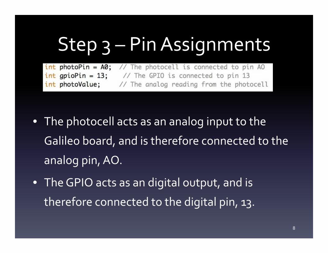
Step 3 – Pin Assignments
• The photocell acts as an analog input to the
Galileo board, and is therefore connected to the
analog pin, AO.
• The GPIO acts as an digital output, and is
therefore connected to the digital pin, 13.
8
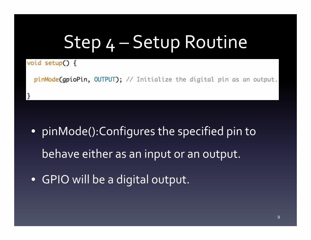
Step 4 – Setup Routine
• pinMode():Configures the specified pin to
behave either as an input or an output.
• GPIO will be a digital output.
9
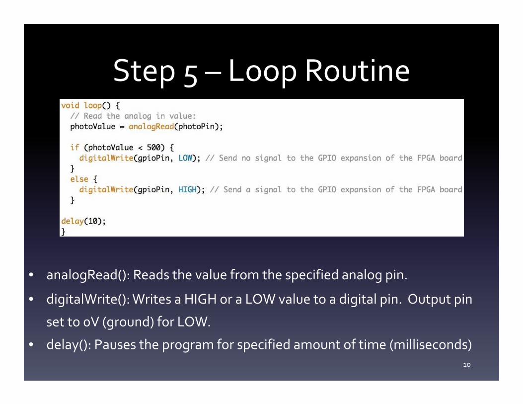
Step 5 – Loop Routine
• analogRead(): Reads the value from the specified analog pin.
• digitalWrite(): Writes a HIGH or a LOW value to a digital pin. Output pin
set to 0V (ground) for LOW.
• delay(): Pauses the program for specified amount of time (milliseconds)10
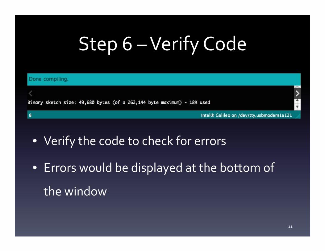
Step 6 – Verify Code
• Verify the code to check for errors
• Errors would be displayed at the bottom of
the window
11
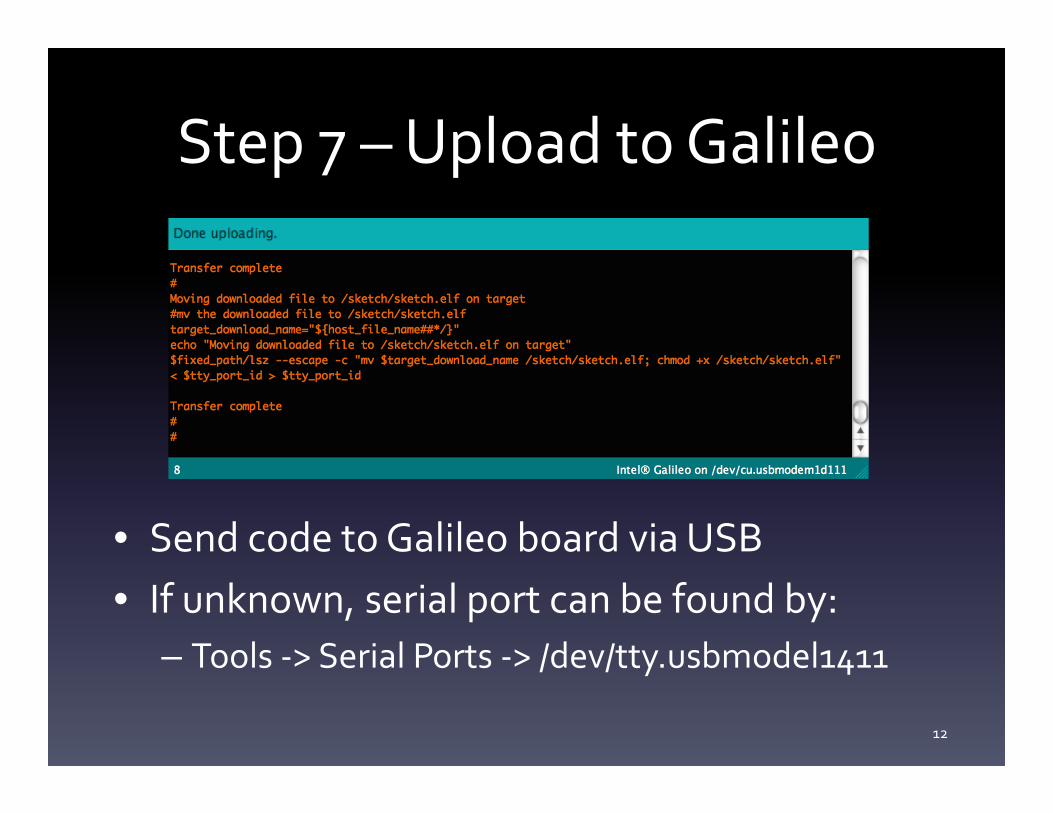
Step 7 – Upload to Galileo
• Send code to Galileo board via USB• If unknown, serial port can be found by:
– Tools -> Serial Ports -> /dev/tty.usbmodel1411
12
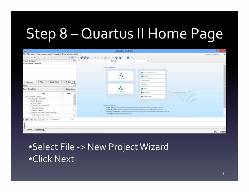
Step 8 – Quartus II Home Page
13
•Select File -> New Project Wizard•Click Next
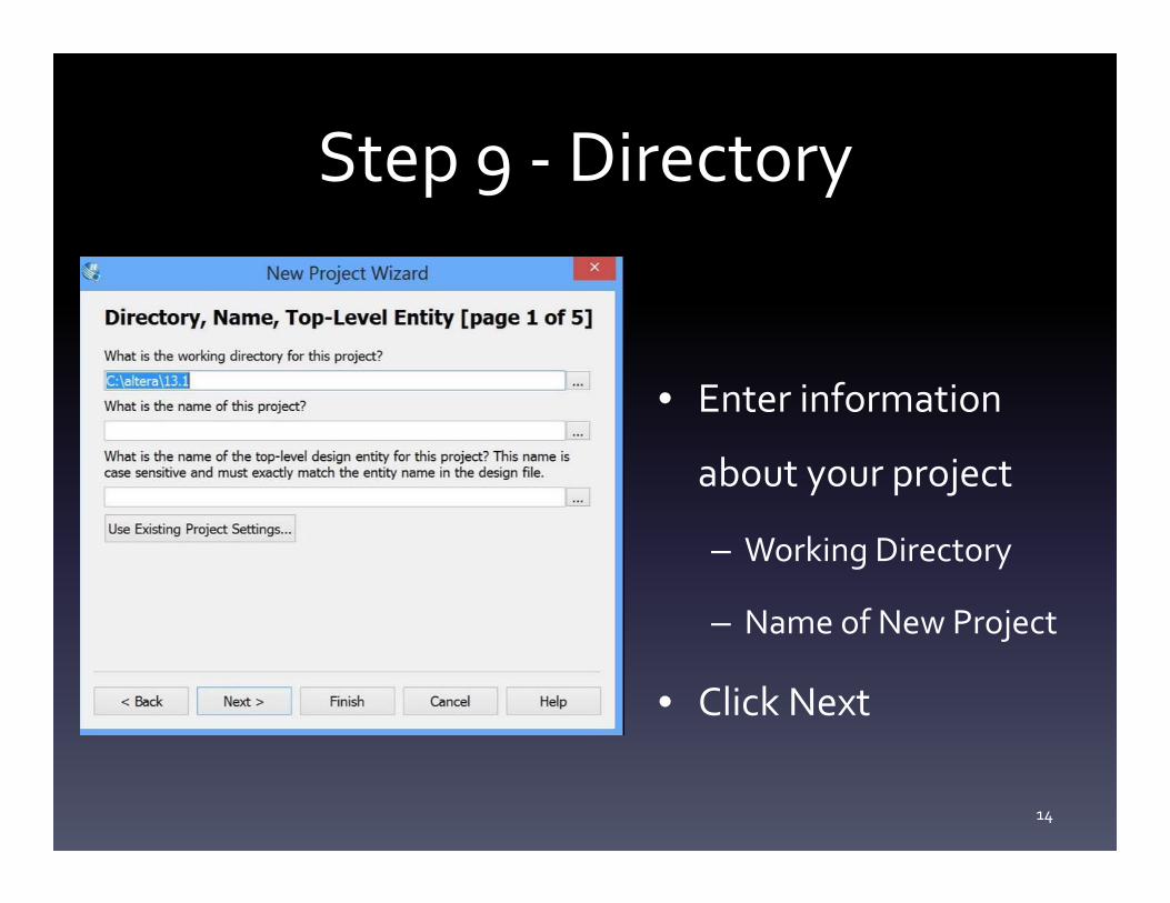
Step 9 - Directory
• Enter information
about your project
– Working Directory
– Name of New Project
• Click Next
14
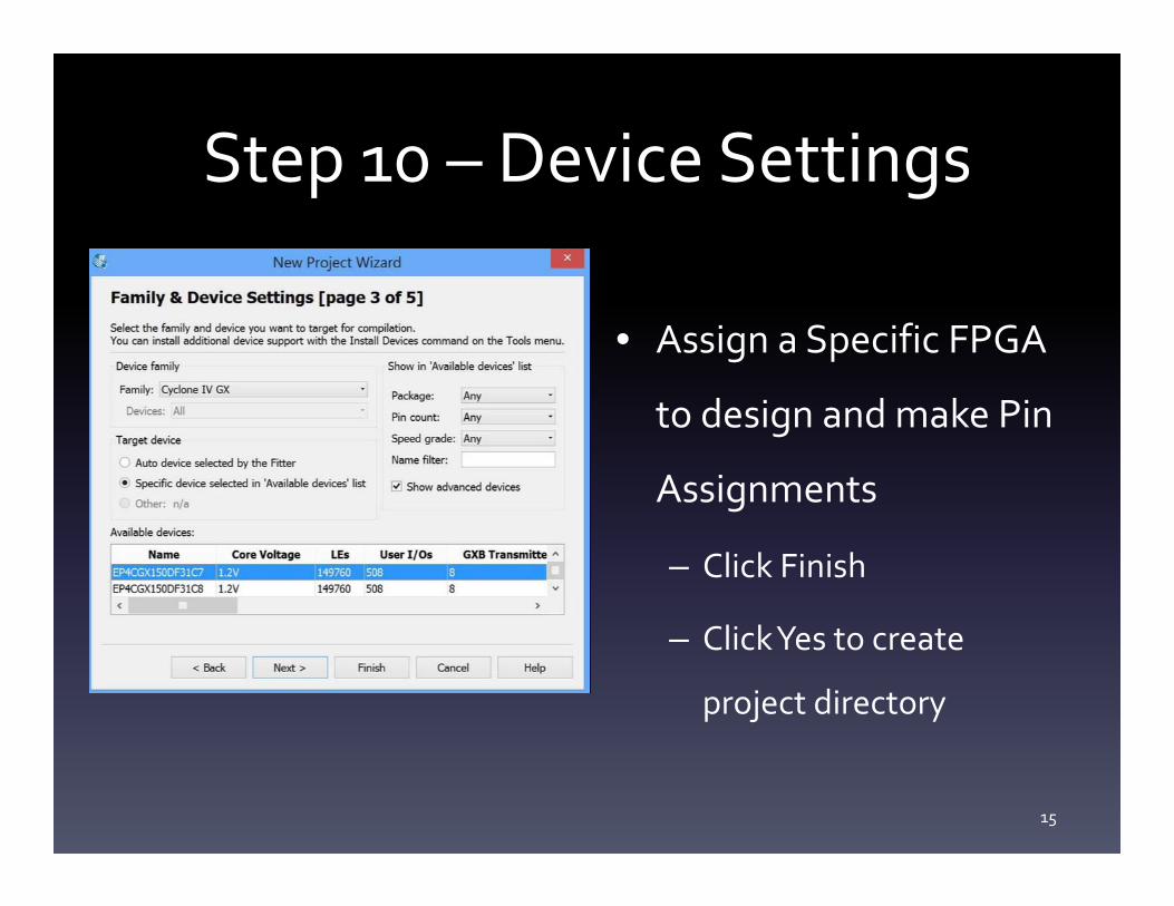
Step 10 – Device Settings
• Assign a Specific FPGA
to design and make Pin
Assignments
– Click Finish
– Click Yes to create
project directory
15
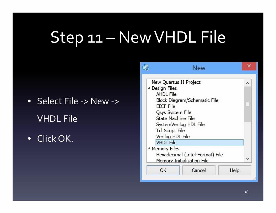
Step 11 – New VHDL File
• Select File -> New ->
VHDL File
• Click OK.
16
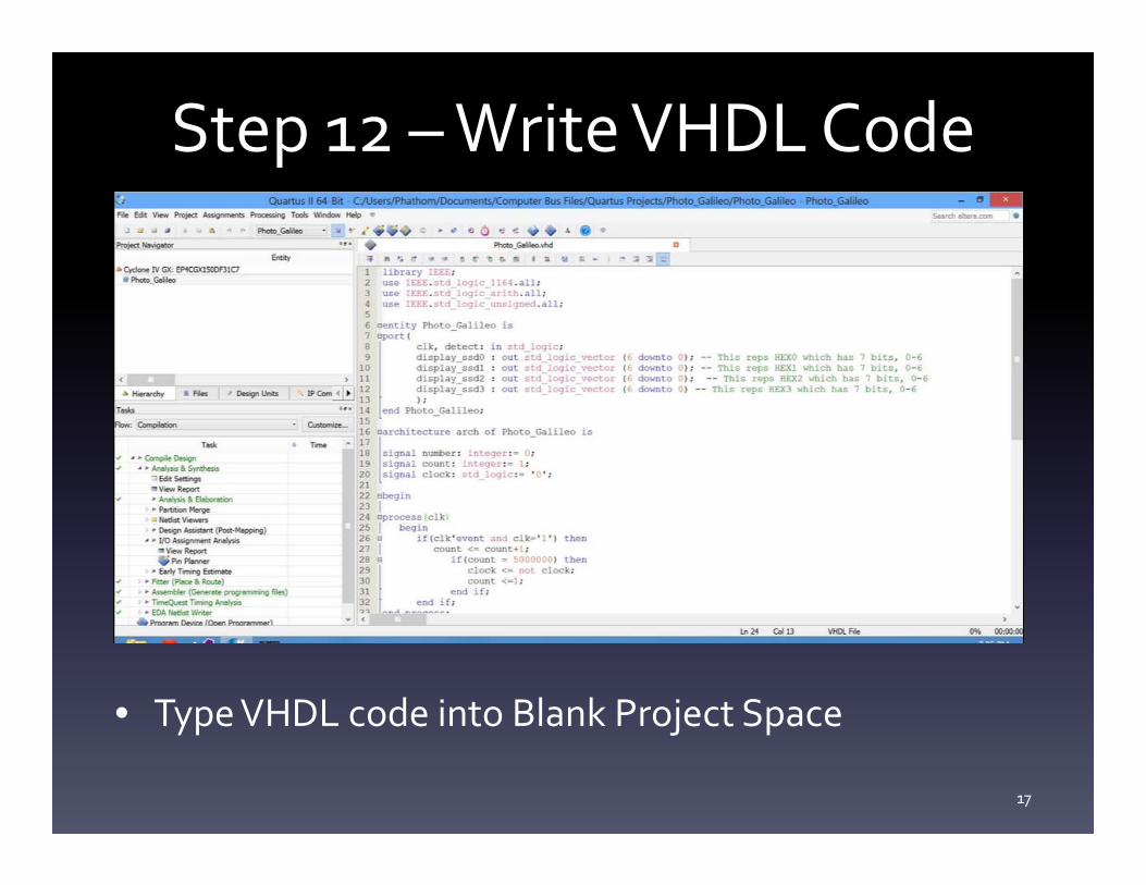
Step 12 – Write VHDL Code
• Type VHDL code into Blank Project Space
17
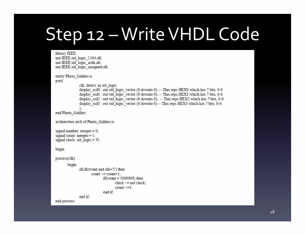
Step 12 – Write VHDL Code
18
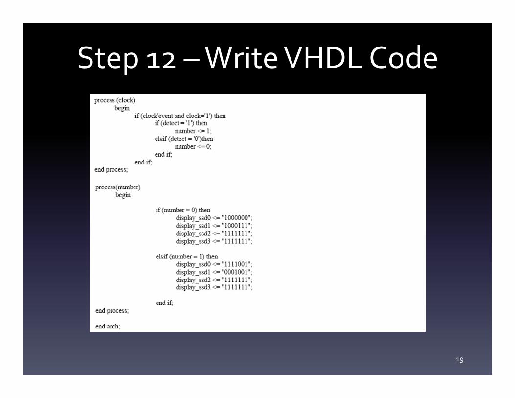
Step 12 – Write VHDL Code
19
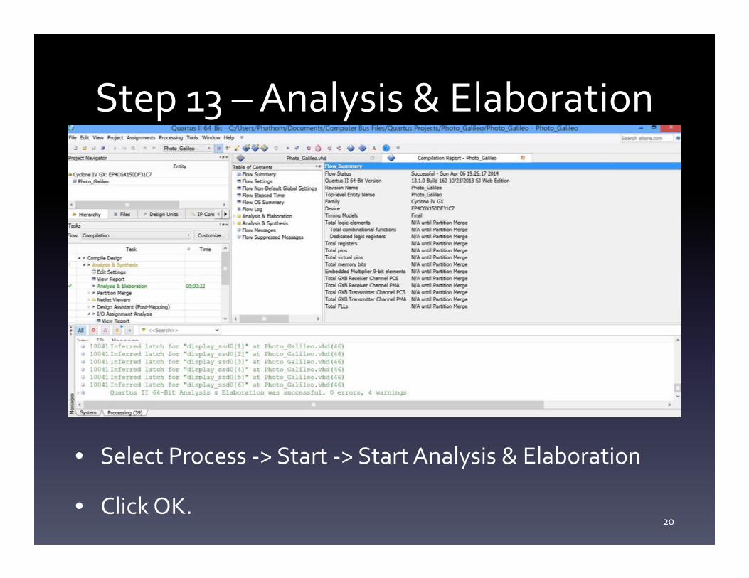
Step 13 – Analysis & Elaboration
• Select Process -> Start -> Start Analysis & Elaboration
• Click OK.20
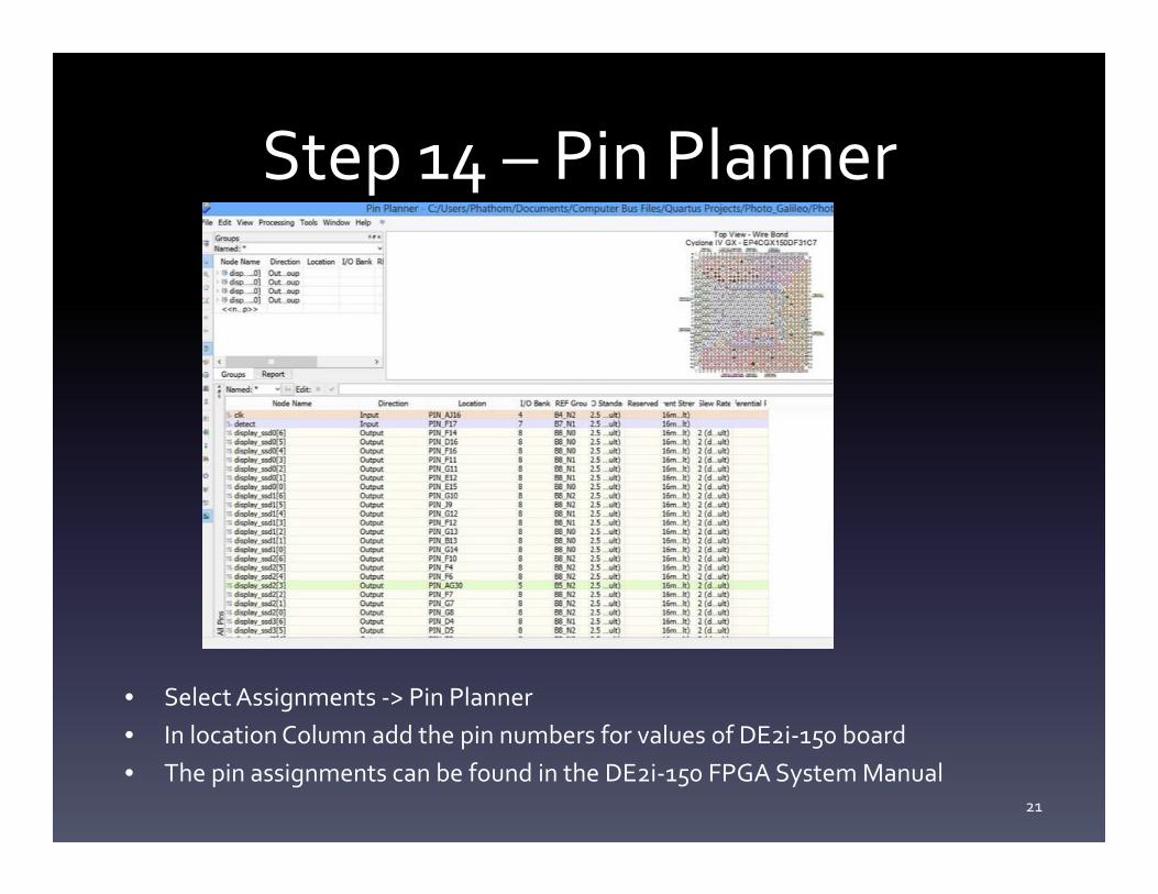
Step 14 – Pin Planner
• Select Assignments -> Pin Planner• In location Column add the pin numbers for values of DE2i-150 board• The pin assignments can be found in the DE2i-150 FPGA System Manual
21
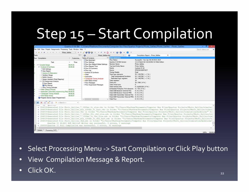
Step 15 – Start Compilation
• Select Processing Menu -> Start Compilation or Click Play button • View Compilation Message & Report.• Click OK. 22
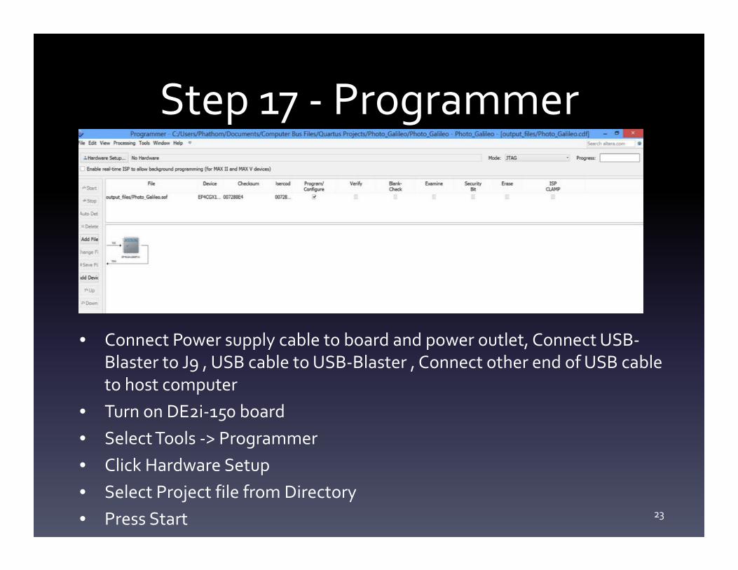
Step 17 - Programmer
• Connect Power supply cable to board and power outlet, Connect USB-Blaster to J9 , USB cable to USB-Blaster , Connect other end of USB cable to host computer
• Turn on DE2i-150 board• Select Tools -> Programmer• Click Hardware Setup• Select Project file from Directory• Press Start 23
Conclusion
• Very fun and easy project.
• Can be modified for more features.
• Unsure if analog values can be displayed on 7-
segment display.
24
References
• http://arduino.cc/en/Reference/analogRead
• http://arduino.cc/en/Reference/digitalWrite
• http://arduino.cc/en/Reference/delay
• http://arduinoarts.com/2011/08/tutorial-led-controlled-by-
photo-sensor/
• http://learn.adafruit.com/photocells/using-a-photocell
• http://arduino.cc/en/Reference/pinMode
25