Embed Size (px)
Citation preview

Galaxy VM
160–225 kVA 480 V,160–200 kVA 400 V
Operation
10/2016
www.schneider-electric.com

Legal InformationThe Schneider Electric brand and any registered trademarks of Schneider ElectricIndustries SAS referred to in this guide are the sole property of Schneider ElectricSA and its subsidiaries. They may not be used for any purpose without the owner'spermission, given in writing. This guide and its content are protected, within themeaning of the French intellectual property code (Code de la propriétéintellectuelle français, referred to hereafter as "the Code"), under the laws ofcopyright covering texts, drawings and models, as well as by trademark law. Youagree not to reproduce, other than for your own personal, noncommercial use asdefined in the Code, all or part of this guide on any medium whatsoever withoutSchneider Electric's permission, given in writing. You also agree not to establishany hypertext links to this guide or its content. Schneider Electric does not grantany right or license for the personal and noncommercial use of the guide or itscontent, except for a non-exclusive license to consult it on an "as is" basis, at yourown risk. All other rights are reserved.
Electrical equipment should be installed, operated, serviced, and maintained onlyby qualified personnel. No responsibility is assumed by Schneider Electric for anyconsequences arising out of the use of this material.
As standards, specifications, and designs change from time to time, please ask forconfirmation of the information given in this publication.

160–225 kVA 480 V, 160–200 kVA 400 V
Table of Contents
Important Safety Instructions — SAVE THESEINSTRUCTIONS.........................................................................................5
Safety Precautions .....................................................................................6
Overview of UPS User Interface...............................................................7Overview of Mimic Diagram.........................................................................8Overview of Status LEDs.............................................................................8Display Menu Tree......................................................................................8
Display Menu Tree – UPS......................................................................9Display Menu Tree – Frequency Converter with Batteries ......................10Display Menu Tree – Frequency Converter ........................................... 11
Display Symbols....................................................................................... 11Overview of Controller Interface.................................................................12
Configuration .............................................................................................13Add a New User or Edit an Existing User ....................................................13Delete a User ...........................................................................................13Configure the Display Preferences.............................................................14Configure the Display Settings...................................................................14Configure the UPS Output Voltage Compensation.......................................15Configure High Efficiency Mode.................................................................16Configure the Redundancy Level of the Parallel System ..............................17Configure the Input Contacts .....................................................................17Configure the Output Relays .....................................................................18Configure Reminder Settings.....................................................................19Configure Battery Alarm Threshold ............................................................19Configure Automatic Battery Test...............................................................20Configure the Network ..............................................................................21Configure the Modbus...............................................................................22Restore Default Configuration....................................................................23
Operation ...................................................................................................24Operation Modes......................................................................................24
UPS Operation Modes ........................................................................24System Operation Modes ....................................................................27
Operation Procedures...............................................................................28Access Password-Protected Screens ...................................................28View the System Status Information .....................................................29Operation Procedures for Single UPS Systems .....................................32Operation Procedures for Parallel UPS Systems ...................................36Operation Procedures for Frequency Converter Systems.......................41Start a Boost Charge of the Batteries....................................................41Access a Configured Network Management Interface............................42
Maintenance ..............................................................................................43Replace the Top Filter ...............................................................................43Replace the Three Bottom Filters...............................................................44
Troubleshooting ........................................................................................45Troubleshooting via the Mimic Diagram LEDs .............................................45
Input LED...........................................................................................45Inverter LED.......................................................................................45
990–4758C–001 3

160–225 kVA 480 V, 160–200 kVA 400 V
Load LED...........................................................................................45Battery LED........................................................................................46Bypass LED .......................................................................................46
Reboot the Display ...................................................................................46Reset the Password..................................................................................47Logs ........................................................................................................47
View the NMC Log ..............................................................................47View the UPS Log...............................................................................49Export Data from Logs.........................................................................49
View the Active Alarms..............................................................................50Alarm Levels ......................................................................................50Alarm Messages.................................................................................50
Tests .......................................................................................................55Perform a Battery Test.........................................................................55Perform a Runtime Calibration .............................................................55Perform an Annunciators Test ..............................................................56Calibrate the Display ...........................................................................56
Determine if you need a Replacement Part .................................................56Find the UPS Serial Number ................................................................57
Return Parts to Schneider Electric .............................................................57
4 990–4758C–001

Important Safety Instructions — SAVE THESEINSTRUCTIONS 160–225 kVA 480 V, 160–200 kVA 400 V
Important Safety Instructions — SAVE THESEINSTRUCTIONS
Read these instructions carefully and look at the equipment to become familiar withit before trying to install, operate, service or maintain it. The following safetymessages may appear throughout this manual or on the equipment to warn ofpotential hazards or to call attention to information that clarifies or simplifies aprocedure.
The addition of this symbol to a “Danger” or “Warning” safetymessage indicates that an electrical hazard exists which will result inpersonal injury if the instructions are not followed.
This is the safety alert symbol. It is used to alert you to potentialpersonal injury hazards. Obey all safety messages with this symbolto avoid possible injury or death.
DANGERDANGER indicates a hazardous situation which, if not avoided, will result indeath or serious injury.
Failure to follow these instructions will result in death or serious injury.
WARNINGWARNING indicates a hazardous situation which, if not avoided, could result indeath or serious injury.
Failure to follow these instructions can result in death, serious injury, orequipment damage.
CAUTIONCAUTION indicates a hazardous situation which, if not avoided, could result inminor or moderate injury.
Failure to follow these instructions can result in injury or equipmentdamage.
NOTICENOTICE is used to address practices not related to physical injury. The safetyalert symbol shall not be used with this type of safety message.
Failure to follow these instructions can result in equipment damage.
Please NoteElectrical equipment should only be installed, operated, serviced, and maintainedby qualified personnel. No responsibility is assumed by Schneider Electric for anyconsequences arising out of the use of this material.
990–4758C–001 5

160–225 kVA 480 V, 160–200 kVA 400 VImportant Safety Instructions — SAVE THESE
INSTRUCTIONS
A qualified person is one who has skills and knowledge related to the construction,installation, and operation of electrical equipment and has received safety trainingto recognize and avoid the hazards involved.
Safety Precautions
DANGERHAZARD OF ELECTRICAL SHOCK, EXPLOSION OR ARC FLASH
All safety instructions in this document must be read, understood and followed.
Failure to follow these instructions will result in death or serious injury.
DANGERHAZARD OF ELECTRICAL SHOCK, EXPLOSION OR ARC FLASH
After the UPS system has been electrically wired, do not start up the system.Start-up must only be performed by Schneider Electric.
Failure to follow these instructions will result in death or serious injury.
6 990–4758C–001

Overview of UPS User Interface 160–225 kVA 480 V, 160–200 kVA 400 V
Overview of UPS User InterfaceThe user interface consists of:A. Display interfaceB. Status LEDsC. Mimic diagramD. Inverter ON buttonE. Inverter OFF buttonF. USB port for export of logsG. Display reset buttonH. Network connection LED:
• Solid green: The system has valid TCP/IP settings.See Configure the Network, page 21.
• Flashing green: The system does not have valid TCP/IP settings.• Solid orange: The display is inoperable. Contact Schneider Electric.• Flashing orange: The system is making BOOTP requests.
See Configure the Network, page 21.• Alternately flashing green and orange: If the LED is alternately flashing
slowly, the system is making DHCP requests.See Configure the Network, page 21.If the LED is alternately flashing rapidly, the system is starting up.
• Off: The display is not receiving input power or the display is inoperable.I. LED for indication of network connection type:
• Solid green: The system is connected to a network operating at 10 Megabitsper second (Mbps).
• Flashing green: The system is receiving or transmitting data packets at 10Megabits per second (Mbps).
• Solid orange: The system is connected to a network operating at 100Megabits per second (Mbps).
• Flashing orange: The system is receiving or transmitting data packets at 100Megabits per second (Mbps).
• Off: One or more of the following exists: The display is not receiving inputpower, the cable that connects the system to the network is disconnected,the device that connects the system to the network is turned off, or thedisplay is inoperable. Check the connections and if the LED remains off,contact Schneider Electric.
J. Slots reserved for service.
990–4758C–001 7

160–225 kVA 480 V, 160–200 kVA 400 V Overview of UPS User Interface
Overview of Mimic Diagram
The mimic diagram shows the power flow through the UPS system, and the statusof the main functions.
Each LED can be in one of the below three states:
Green The corresponding function is active and OK
Red The corresponding function is not workingproperly
Off The corresponding function is not active
Overview of Status LEDsThe status LEDs placed next to the display interface shows the current status ofthe UPS system:
• Green: The load is protected• Green + Orange: The load is protected, but the system
reports an alarm at warning level• Orange + Red: The load is unprotected and the system
reports an alarm at warning level and an alarm at criticallevel
• Red: The load is unprotected and the system reports analarm at critical level
Display Menu TreeThe menus available are dependent on how the system is configured to operate:• As a UPS• As a frequency converter with batteries• As a frequency converter
8 990–4758C–001

Overview of UPS User Interface 160–225 kVA 480 V, 160–200 kVA 400 V
Display Menu Tree – UPS
NOTE: The control and configuration screens are password-protected.
990–4758C–001 9

160–225 kVA 480 V, 160–200 kVA 400 V Overview of UPS User Interface
Display Menu Tree – Frequency Converter with Batteries
NOTE: The control and configuration screens are password-protected.
10 990–4758C–001

Overview of UPS User Interface 160–225 kVA 480 V, 160–200 kVA 400 V
Display Menu Tree – Frequency Converter
Display Symbols
Symbol Description
The locked home button appears when the system is locked by apassword protection. Tap this button to go to the home screen of thedisplay.
The unlocked home button appears when the system has beenunlocked using the password. Tap this button to go to the homescreen of the display.
Tap the OK button to confirm your selections and exit the currentscreen.
990–4758C–001 11

160–225 kVA 480 V, 160–200 kVA 400 V Overview of UPS User Interface
Symbol Description
Tap the ESC button to cancel your changes and exit the currentscreen.
Tap the filter button to set up the filters for your logs.
Tap the recycle bin button to clear the log.
Overview of Controller InterfaceFront View of Power Cabinet
A. Two Smart Slots for optional Network Management CardsB. Modbus and modbus dip switch settingsC. Ethernet
12 990–4758C–001

Configuration 160–225 kVA 480 V, 160–200 kVA 400 V
Configuration
Add a New User or Edit an Existing User1. From the home screen on the display select Configuration > Display >
Security.2. Select Add User to add a new user or select Edit User to edit an existing user
of the system.
3. In the Name field, type in the name of the user. Complete with Enter.4. In the Pin field, type in a pin code for the user. Complete with Enter.5. In the Confirm Pin field, retype the pin code of the user. Complete with Enter.6. Tap OK to save your settings.
Delete a User1. From the home screen on the display select Configuration > Display >
Security > Delete User.2. Browse to the user that you wish to delete using the up and down arrows and
tap OK.3. Tap Yes to confirm deletion of an existing user of the system.
990–4758C–001 13

160–225 kVA 480 V, 160–200 kVA 400 V Configuration
Configure the Display Preferences1. From the home screen on the display select Configuration > Display >
Preferences.
2. Select the preferred language using the up and down arrows.
3. Select the preferred date format using the up and down arrows.
4. Select the preferred temperature units: US Customary (°Fahrenheit) or Metric(°Celsius).
5. Set the current date and time using one of the below two methods:
– Set the date and time manually on the display by selecting Manual andtyping the actual date and time and completing with Enter.
– Set the date and time automatically by selecting Synchronize with the NTPserver (Network Time Protocol server).
NOTE: NTP server settings can be configured in the network managementinterface via the Web.
6. Tap OK to save your settings.
Configure the Display Settings1. From the home screen on the display select Configuration > Display >
System Settings.
2. Set the Alarm Volume. Choose between: Off, Low, Medium, and High.
14 990–4758C–001

Configuration 160–225 kVA 480 V, 160–200 kVA 400 V
3. Set the Button Volume. Choose between: Off, Low, Medium, and High.4. Set the Brightness of the display. Choose between: Low, Medium, and High.5. Enable or disable Backlight Timeout. If you wish to enable backlight timeout,
set the time limit in minutes for enabling backlight timeout. Choose between:60, 30, 10, 5, and 1.
6. Set the intensity of the backlight. Choose between: Off, Very Low, Low, andMedium.
7. Set the time limit in minutes for automatic log off. Choose between: 60, 30, 10,5, and 1.
8. Tap OK to save your settings.
Configure the UPS Output Voltage Compensation1. From the home screen on the display select Configuration > UPS > Output.2. Tap arrow to the right to go to the next output configuration screen.
3. Under Voltage Compensation select the preferred voltage compensation foryour system. Choose between –3%, –2%, –1%, 0%, 1%, 2%, or 3%.
NOTE: This setting is shared between all UPSs in a parallel system.
990–4758C–001 15

160–225 kVA 480 V, 160–200 kVA 400 V Configuration
4. Under Output Voltage Compensation with Loaded Transformer select thepreferred output voltage compensation to compensate for load dependenttransformer voltage drop. Choose between 0%, 1%, 2%, or 3%.
NOTE: This setting must be identical for all UPSs in a parallel system.
NOTE:When this setting is set to 0%, the output transformer voltagecompensation is disabled.
5. Tap OK to confirm your setting.
Configure High Efficiency ModeNOTE: ECO Mode must be enabled by Schneider Electric during serviceconfiguration to make this selection available.
1. From the home screen on the display select Configuration > UPS > HighEfficiency Mode and configure the following settings:
a. Select High Efficiency Mode: Choose between Disable, ECO Mode,ECOnversion, and ECOnversion with Harmonics Compensation.
2. Tap > and configure the schedule settings:
a. Schedule: Select when the system should enter the selected ECOnversionor ECO mode. Choose between Always, Programmed and Never.
b. Active Schedules List: If you chose Programmed above, select Enableand set the time and date for when the system should enter the selectedECOnversion or ECO mode.
16 990–4758C–001

Configuration 160–225 kVA 480 V, 160–200 kVA 400 V
3. Tap OK to confirm your settings.
Configure the Redundancy Level of the Parallel SystemThis procedure sets the redundancy level of your parallel system. The parallelsystem can contain up to five UPS units:• a 4+1 system with four UPS units in capacity and one in redundancy• a 5+0 system with five UPS units for capacity
1. From the home screen on the display select Configuration > UPS > ParallelSystem.
2. Under Parallel system redundancy select the redundancy for your UPSsystem. Choose between N+0, N+1, N+2, N+3, N+4.
3. Tap OK to confirm your setting.
Configure the Input Contacts1. On the display select Configuration > Input Contacts and select the input
contact that you wish to configure.
990–4758C–001 17

160–225 kVA 480 V, 160–200 kVA 400 V Configuration
2. Choose between the below six options:
Custom Input 1 External Battery Monitor Detected Fault
Custom Input 2 Battery Room Ventilation Inoperable
Ground fault Supplied By Genset
Flywheel inoperable Disable High Efficiency Mode
3. Tap OK to save your settings.
Configure the Output Relays1. On the display select Configuration > Output Relays and select the output
relay that you wish to configure.
2. Select the function that you wish to use the specific output relay for from the listbelow:
Common Alarm Normal Operation
Battery Operation1 Maintenance Bypass2
Static Bypass1 High Efficiency Mode
Output Overload Fan Inoperable
Battery is not Working Correctly1 Battery Disconnected1
Battery Voltage Low1 Input Out of Tolerance
Bypass Out of Tolerance2 UPS Warning
UPS Critical Parallel Redundancy Lost
External Fault UPS Maintenance Mode
System Critical System Warning
System Common Alarm
3. Set the delay in seconds for the specific output to activate. Select a valuebetween 0 and 60 seconds.
4. Tap OK to save your settings.
18 990–4758C–001
1. Not available when operating as a frequency converter without batteries2. Not available when operating as a frequency converter

Configuration 160–225 kVA 480 V, 160–200 kVA 400 V
Configure Reminder SettingsWhen the air filters have been replaced, the reminders settings must be updated.
1. From the home screen on the display select Configuration > Reminders.
2. Configure the following settings:
a. Reminders Signalling: Select Enable to enable the display of allreminders.
b. Reminder: Select Enable to enable the display of reminders for air filterreplacement.
c. Duration before 1st Reminder: Set the time in weeks before the firstreminder is shown.
d. Elapsed Time: Manually set the number of days that the air filters havebeen used.
3. Tap OK to confirm your settings.
Configure Battery Alarm Threshold1. From the home screen on the display select Configuration > Battery >
Alarms.
2. Select your preferred battery alarm threshold in seconds. Select a valuebetween 60 and 6000 seconds and complete with Enter.
990–4758C–001 19

160–225 kVA 480 V, 160–200 kVA 400 V Configuration
3. Tap OK to confirm your setting.
Configure Automatic Battery Test1. From the home screen on the display select Configuration > Battery > Test.
2. Set your preferred settings for the automatic battery test:
a. Battery Test Interval: Select your preferred interval for battery tests.Choose between: Never, Every 52 Weeks, Every 26 Weeks, Every 12Weeks, Every 8 Weeks, Every 4 weeks, Every 2 Weeks, or Once a Week.
NOTE: If you run battery tests too frequently it can reduce the lifetime of thebatteries.
b. Battery Test Start Time: Select the time of the day in 24 hour format thatthe test should take place and complete with Enter.
c. Battery Test Day of the Week: Select the day of the week that the testshould take place and complete with Enter.
3. When all settings have been completed, tap OK to confirm your settings.
20 990–4758C–001

Configuration 160–225 kVA 480 V, 160–200 kVA 400 V
Configure the NetworkThe network can be configured for the display and for the cards in Smart Slot 1 andSmart Slot 2.
1. From the home screen on the display select Configuration > Network andselect either Display, Smart Slot 1, or Smart Slot 2 if present.
2. Configure the following settings:
a. TCP/IPv4: Enable IPv4 (if applicable), and select the Address Mode(Manual, DCHP, or BOOTP).
b. TCP/IPv6: Enable IPv6 (if applicable), select Auto Configuration orManual Configuration, and select the DHCPv6 Mode (Router controlled,Non-Address Information Only, Never, or Address and OtherInformation).
NOTE: Tap Addresses to see all valid IPv6 addresses.
990–4758C–001 21
160–225 kVA 480 V, 160–200 kVA 400 V Configuration
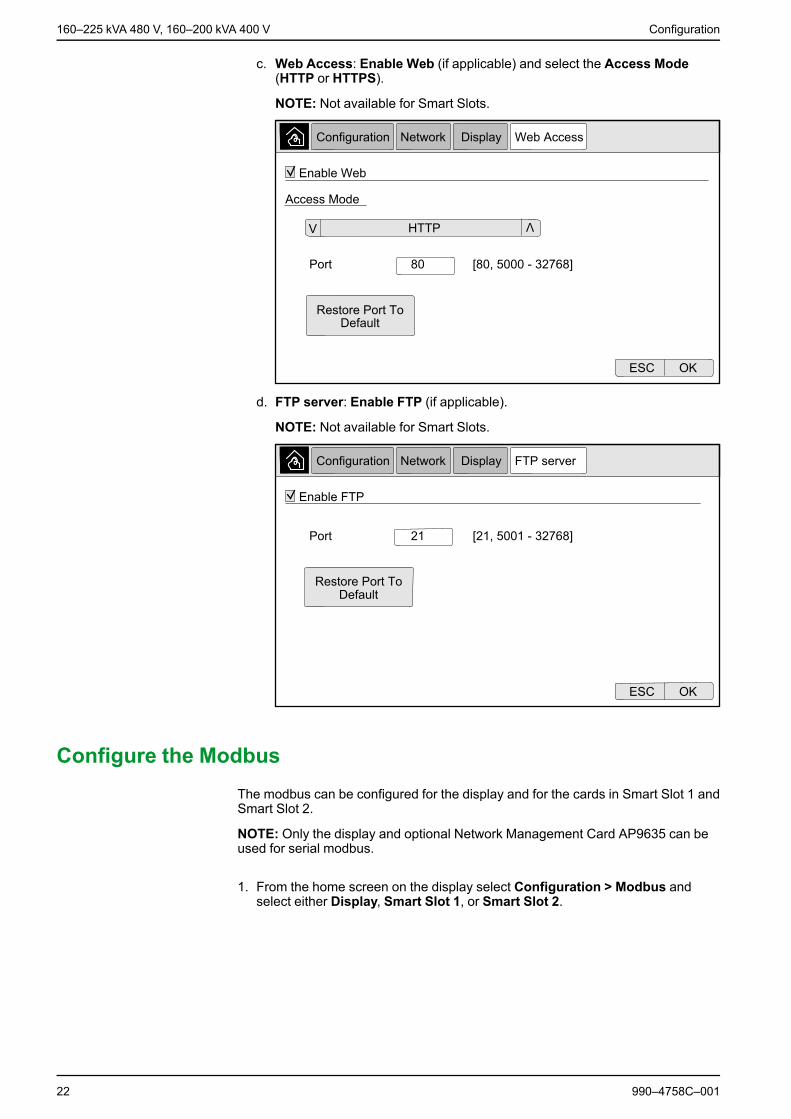
c. Web Access: Enable Web (if applicable) and select the Access Mode(HTTP or HTTPS).
NOTE: Not available for Smart Slots.
d. FTP server: Enable FTP (if applicable).
NOTE: Not available for Smart Slots.
Configure the ModbusThe modbus can be configured for the display and for the cards in Smart Slot 1 andSmart Slot 2.
NOTE: Only the display and optional Network Management Card AP9635 can beused for serial modbus.
1. From the home screen on the display select Configuration > Modbus andselect either Display, Smart Slot 1, or Smart Slot 2.
22 990–4758C–001

Configuration 160–225 kVA 480 V, 160–200 kVA 400 V
2. Configure the modbus by enabling Serial or TCP access, and adding theneeded values.
3. Tap OK to confirm your settings.
Restore Default Configuration1. From the home screen on the display select Configuration > Restore
Defaults.
2. Select one of the below options:
– Restart Network Interface: Select this option to restart network interface.– Reset All: Select this option to reset all settings to default. You can select to
leave out the TCP/IP settings from the reset procedure.– Reset Only: Select this option if you only wish to reset parts of the settings
to default values. You can select to reset the following settings: TCP/IP,Event Configuration, and Display Settings.
3. When you have made your selection, tap OK to reset the selected settings todefault.
990–4758C–001 23

160–225 kVA 480 V, 160–200 kVA 400 V Operation
Operation
Operation ModesThe Galaxy UPS has two different levels of operation mode:• UPS Operation Mode: The operation mode of the operated UPS• System Operation Mode: The operation mode of the complete UPS system
UPS Operation Modes
Normal
During normal operation, the UPS supports the load with conditioned power. Whilethe UPS is in normal operation, the input, inverter, and load LEDs are green, andthe battery and bypass LEDs are off.
Battery
If the utility/mains supply fails, the UPS transfers to battery operation and supportsthe load with conditioned power from the DC source. While the UPS system is inbattery operation, the battery, inverter, and load LEDs are green, the bypass LEDis off and the input LED is red.
Requested Static Bypass
The UPS can be transferred to requested static bypass following a command fromthe display. During static bypass operation, the load is supplied from the bypasssource. If a fault is detected, the UPS will transfer to normal operation or forcedstatic bypass operation. If there is an interruption to the utility/mains power supplyduring requested static bypass operation, the system will transfer to batteryoperation. The load may experience a short duration interruption of power (4 to 8ms) during the transfer from requested static bypass.
During requested static bypass, the input, bypass and output LEDs are green andthe battery and inverter LEDs are off.
24 990–4758C–001

Operation 160–225 kVA 480 V, 160–200 kVA 400 V
Forced Static Bypass
The UPS is in forced static bypass following a command from the UPS system orbecause the user has pressed the inverter OFF button on the UPS. During forcedstatic bypass operation, the load is supplied directly by the bypass source.
During forced static bypass, the input, bypass and output LEDs are green and thebattery and inverter LEDs are off or red if an alarm is present.
NOTE: The batteries are not available as an alternate power source while the UPSis in forced static bypass operation.
Maintenance Bypass Operation
When the Maintenance Bypass Breaker (MBB) is closed, the UPS system entersmaintenance bypass operation. The load is supplied with unconditioned powerfrom the bypass input.
NOTE: The batteries are not available as an alternate power source while the UPSis in maintenance bypass operation.
Static Bypass Standby
NOTE: Static bypass standby is only applicable to an individual UPS in a parallelsystem.
The UPS enters static bypass standby if the UPS is prevented from entering forcedstatic bypass and the other UPS units of the parallel system can support the load.
In static bypass standby the output of the specific UPS is off.
The UPS automatically changes to the preferred operation mode when possible.
NOTE: If the other UPS units cannot support the load, the parallel system entersforced static bypass. The UPS in static bypass standby will then transfer to forcedstatic bypass.
Inverter Standby
NOTE: Inverter standby is only applicable to an individual UPS in a parallelsystem.
The UPS enters inverter standby if there is an interruption to the utility/mainssupply of one UPS and the other UPS units of the parallel system can support theload with the configured redundancy level maintained. This is to avoid that thebatteries are being drained in situations where it is not necessary.
Battery Test
The UPS is in battery test mode when the UPS is performing a battery self-test or aruntime calibration.
NOTE: The battery test will be aborted if the utility/mains supply is interrupted or acritical alarm is present and will return to normal operation upon return of utility/mains.
990–4758C–001 25

160–225 kVA 480 V, 160–200 kVA 400 V Operation
ECO Mode
NOTE: ECO mode must be enabled by a Schneider Electric field service engineer.
ECO mode allows the UPS to be configured to use requested static bypass, withthe load supplied through the bypass, as the preferred operation mode underpredefined circumstances.
If a fault is detected (bypass voltage out of tolerance, output voltage out oftolerance, etc), the UPS will immediately change to normal operation or forcedstatic bypass.
The main advantage of ECO mode is a reduction in the consumption of electricalpower.
In case of interruption to the utility/mains supply, the UPS transfers to inverteroperation for a continuous supply of the load.
The load may experience a short duration interruption of power (4 to 8 ms) duringthis transfer.
The batteries are charged when the UPS is in ECO mode.
NOTE:When changes to ECO mode settings are made on one UPS in a parallelsystem, the settings are shared to all UPSs in the parallel system.
ECOnversion Mode
ECOnversion allows the system to supply the active part of the load through thebypass. The inverter is kept running in parallel with the bypass source and suppliesthe reactive part of the load.
The input power factor of the UPS is, regardless of the load power factor,maintained close to unity as the reactive part of the load is significantly reduced inthe UPS input current.
In case of an interruption to the utility/mains supply, the inverter immediatelymaintains the output voltage so that breaks or drops during the transfer fromECOnversion mode are practically eliminated.
The batteries are charged when the UPS is in ECOnversion mode.
NOTE:When changes to ECOnversion settings are made on one UPS in a parallelsystem, the settings are shared to all UPSs in the parallel system.
Self-test
After start-up of the UPS system, the UPS will perform an automatic self-test. Thestatus and progress of the self-test are indicated by the flashing LEDs on the mimicdiagram.
When the self-test has been passed, the LEDs will indicate the operation mode ofthe UPS system.
26 990–4758C–001

Operation 160–225 kVA 480 V, 160–200 kVA 400 V
NOTE: If an LED continues to flash after completion of the self-test, please callSchneider Electric.
For more information on self-test, see Troubleshooting via the Mimic DiagramLEDs after Self-Test.
Off
When the UPS is in off, the UPS does not supply the connected load with power.
System Operation Modes
The system operation mode indicates the current output status of the completeUPS system and which source that supplies the load.
Inverter
In inverter operation the load is supplied by the inverters. The UPS mode can be ineither normal or battery operation when the system operation mode is inverteroperation.
Requested Static Bypass
When the system is in requested static bypass, the load is supplied from thebypass source. If a fault is detected, the system will transfer to inverter operation orforced static bypass operation. The load may experience a short durationinterruption of power (4 to 8 ms) during the transfer from requested static bypass.
Forced Static Bypass
The system is in forced static bypass following a command from the UPS systemor because the user has pressed the inverter OFF button on the UPS units. Duringstatic bypass operation, the load is supplied directly by the bypass source.
NOTE: The batteries are not available as an alternate power source while thesystem is in forced static bypass operation.
Maintenance Bypass
In maintenance bypass operation, the load is supplied by unconditioned powerfrom the bypass input via the maintenance bypass breaker.
NOTE: The batteries are not available as an alternate power source inmaintenance bypass operation.
ECO Mode
NOTE: ECO mode must be enabled by a Schneider Electric field service engineer.
ECO Mode allows the system to be configured to use requested static bypass, withthe load supplied through the bypass, as the preferred operation mode underpredefined circumstances.
The main advantage of ECO mode is a reduction in the consumption of electricalpower.
In case of interruption to the utility/mains supply, the UPS transfers to inverteroperation for a continuous supply of the load.
The load may experience a short duration interruption of power (4 to 8 ms) duringthis transfer.
990–4758C–001 27

160–225 kVA 480 V, 160–200 kVA 400 V Operation
ECOnversion Mode
ECOnversion allows the system to supply the active part of the load through thebypass. The inverter is kept running in parallel with the bypass source and suppliesthe reactive part of the load.
The input power factor of the UPS is, regardless of the load power factor,maintained close to unity as the reactive part of the load is significantly reduced inthe UPS input current.
In case of an interruption to the utility/mains supply, the inverter immediatelymaintains the output voltage so that breaks or drops during the transfer fromECOnversion mode are practically eliminated. The behaviour is the same for allUPSs in the parallel system.
Off
When the system operation mode is off, the UPS system does not supply theconnected load with power.
Operation Procedures
Access Password-Protected Screens
1. When prompted for the password, select your username.
2. Type in the pin code for your username.
NOTE: The default pin code is 1234.
28 990–4758C–001

Operation 160–225 kVA 480 V, 160–200 kVA 400 V
View the System Status Information
1. From the home screen on the display select Status.2. Select the area for which you wish to see the status. Choose between:
Input
Phase-to-Neutral3
Voltage (phase-to-neutral) The present phase-to-neutral input voltage in volts (V).
Current The present input current from the AC utility power source per phase in amperes (A).
Maximum RMS Current The maximum current for the latest 30 days.
Apparent Power The present apparent power input for each phase in kVA. Apparent power is the product ofRMS (root mean square) volts and RMS amperes.
Active Power The present active power (or real power) input for each phase in kilowatts (kW). Activepower is the portion of power flow that, averaged over a complete cycle of the ACwaveform, results in net transfer of energy in one direction.
Power Factor The ratio of the active power to apparent power.
Phase-to-Phase
Voltage (phase-to-phase) The present phase-to-phase input voltage.
Total Apparent Power The present total apparent power input (for all three phases) in kVA.
Total Active Power The present total active power input (for all three phases) in kW.
Frequency The present input frequency in hertz (Hz).
Energy The total energy consumption since the time of installation or since the number was reset.
990–4758C–001 29
3. Only applicable in systems with neutral connection.

160–225 kVA 480 V, 160–200 kVA 400 V Operation
Output
Phase-to-Neutral4
Voltage (phase-to-neutral) The phase-to-neutral output voltage at the inverter in volts (V).
Current The present output current for each phase in amperes (A).
Maximum RMS Current The maximum current for the latest 30 days.
Apparent Power The present apparent power output for each phase in thousands of Volt-Amps (kVA).Apparent power is the product of RMS (root mean square) volts and RMS amperes.
Active Power The present active power (or real power) output for each phase in kilowatts (kW). Activepower is the portion of power flow that, averaged over a complete cycle of the ACwaveform, results in net transfer of energy in one direction.
Power Factor The present output power factor for each phase. Power factor is the ratio of active power toapparent power.
Current Crest Factor The present output crest factor for each phase. The output crest factor is the ratio of thepeak value of the output current to the RMS (root mean square) value.
Current THD The THD (total harmonic distortion) for each phase, as a percentage, for the present outputcurrent.
Phase-to-Phase
Voltage (phase-to-phase) The phase-to-phase output voltage at the inverter in volts (V).
Total Apparent Power The present apparent power output for each phase in thousands of Volt-Amps (kVA).Apparent power is the product of RMS (root mean square) volts and RMS amperes.
Total Active Power The present total active output power (for all three phases) in kilowatts (kW).
Load The percentage of the UPS capacity presently used across all phases. The loadpercentage for the highest phase load is displayed.
Neutral Current1 The present output neutral current in amperes (A).
Frequency The present output frequency in hertz (Hz).
Inverter Status The general condition of the inverter.
PFC Status The general condition of the PFC.
Energy The total energy supplied since the time of installation or since the value was reset.
30 990–4758C–001
4. Only applicable in systems with neutral connection.

Operation 160–225 kVA 480 V, 160–200 kVA 400 V
Bypass
Phase-to-Neutral5
Voltage (phase-to-neutral) The present phase-to-neutral bypass voltage (V).
Current The present bypass current for each phase, in amperes (A).
Maximum RMS Current The maximum current for the latest 30 days.
Apparent Power The present apparent bypass power for each phase in thousands of Volt-Amps (kVA).Apparent power is the product of RMS (root mean square) volts and RMS amperes.
Active Power The present active bypass power for each phase in kilowatts (kW). Active power is the timeaverage of the instantaneous product of voltage and current.
Power Factor The present bypass power factor for each phase. Power factor is the ratio of active powerto apparent power.
Phase-to-Phase
Voltage (phase-to-phase) The present phase-to-phase bypass voltage (V).
Total Apparent Power The present total apparent bypass power (for all three phases) in thousands of Volt-Amps(kVA).
Total Active Power The present total active bypass power (for all three phases) in kilowatts (kW).
Frequency The present bypass frequency in hertz (Hz).
Battery
Voltage The present battery voltage.
Current The present battery current in amperes (A).A positive current indicates that the battery is charging; a negative current indicates that thebattery is discharging.
Power The present DC power being drawn from the battery, in kilowatts (kW).
Estimated Charge Level The present battery charge, as a percentage of full charge capacity.
Estimated Charge Time The estimated time, in minutes, until the batteries reach 100% charge.
Runtime Remaining The amount of time in hours and minutes before the batteries reach the low-voltageshutdown level.
Charger Mode The operation mode of the charger (Off, Float, Boost, Equalization, Cyclic, Test).
Battery Status The general condition of the battery.
Charger Status The general condition of the charger.
Total Battery Capacity The total capacity available from the available batteries.
Temperature
Ambient Temperature Ambient temperature in degrees Celsius or Fahrenheit at the air intake of the UPS.
Exhaust Air Temperature Exhaust air temperature in degrees Celsius or Fahrenheit at the air exhaust of the UPS.
990–4758C–001 31
5. Only applicable in systems with neutral connection.

160–225 kVA 480 V, 160–200 kVA 400 V Operation
System
Output Voltage The phase-to-phase output voltage at the inverter in volts (V).
Output Current The present output current for each phase in amperes (A).
Output Frequency The present output frequency in hertz (Hz).
Runtime Remaining The amount of time in hours and minutes before the batteries reach the low-voltageshutdown level.
System Time The time of the UPS system.
UPS Operation Mode The operation mode of the operated UPS.
System Operation Mode The operation mode of the complete UPS system.
Total Output Power The apparent and active power (or real power) output for each phase.
Output Power The phase-to-phase apparent and active power (or real power) output for each phase.
Parallel System
Input Current The present phase-to-phase input current in amperes (A).
Output Current The present phase-to-phase output current in amperes (A).
Bypass Current The present phase-to-phase bypass current in amperes (A).
Parallel UPS Number The parallel UPS number of the operated UPS.
Parallel system redundancy The redundancy for the parallel system.
Number of Parallel Units The total number of UPSs in the parallel system.
Parallel Units The numbers of all UPSs in the parallel system.
Output Total Apparent Power The present total apparent output power (for all three phases) in thousands of Volt-Amps(kVA).
Output Total Load The percentage of the UPS system capacity presently used across all phases. The loadpercentage for the highest phase load is displayed.
Active Alarms
Active Alarms For more information on active alarms, go to View the Active Alarms, page 50.
Mimic
Mimic The mimic diagram shows the current status of the main parts of the UPS system: powersources, converters, bypass static switch and breakers, and it shows the power flowthrough the system.
3. Tap the home button to exit the screens and return to the home screen.
Operation Procedures for Single UPS Systems
Start Up Single System from Maintenance Bypass Operation
Use this procedure to start up a single system from maintenance bypass operationwith the load supplied through the MBB and all other breakers open.
NOTE: Only operate a breaker when the associated breaker LED is green.
32 990–4758C–001

Operation 160–225 kVA 480 V, 160–200 kVA 400 V
Front View of Single UPS
1. Close the unit input breaker UIB on the front of the I/O cabinet.This will power up the display interface after approximately 30 seconds.
2. From the home screen on the display, select Control > Startup Wizard. SelectStartup from Maintenance Bypass and follow the steps which appear on thescreen.
NOTE: The following is a generic startup procedure. Always follow the steps ofthe Startup Wizard which are specific to your system.
3. Close the static switch input breaker SSIB on the front of the I/O cabinet.
4. Close the battery breakers in your specific battery solution.
5. Initiate transfer to static bypass by tapping the Transfer Load to static bypassbutton on the display interface.
In systems with kirk-keys, the key is released from the solenoid key releaseunit.
If the UPS system does not transfer to requested static bypass, go to Status >Active Alarms to see if there are active alarms that prevent the UPS systemfrom transferring to static bypass.
6. In systems with kirk-keys, insert the key in the lock on the unit output breakerUOB and turn to unlock.
7. Close the unit output breaker UOB.
8. Open the maintenance bypass breaker MBB.The system transfers to normal operation.
9. In systems with kirk-keys, turn the key in the lock of the maintenance bypassbreaker MBB to lock open.
The key is released.
990–4758C–001 33

160–225 kVA 480 V, 160–200 kVA 400 V Operation
10.In systems with kirk-keys, insert the key in the solenoid key release unit.
Shut Down Single System from Normal to Maintenance BypassOperation
Use this procedure to shut down a single system to maintenance bypass operationwith the load supplied through the MBB.
NOTE: Only operate a breaker when the associated breaker LED is green.
Front View of Single UPS
1. From the home screen on the display, select Control > Shutdown Wizard.Select Shut down ending in Maintenance Bypass and follow the steps whichappear on the screen.
NOTE: The following is a generic shutdown procedure. Always follow the stepsof the Shutdown Wizard which are specific to your system.
2. Initiate transfer to static bypass by tapping the Transfer Load to static bypassbutton on the display interface.
In systems with kirk-keys, the key is released from the solenoid key releaseunit.
If the UPS system does not transfer to requested static bypass, go to Status >Active Alarms to see if there are active alarms that prevent the UPS systemfrom transferring to static bypass.
3. In systems with kirk-keys, insert the key in the lock on the maintenance bypassbreaker MBB and turn to unlock.
4. Close the maintenance bypass breaker MBB on the front of the I/O cabinet.In systems with kirk-keys, the key is held in the lock.
34 990–4758C–001

Operation 160–225 kVA 480 V, 160–200 kVA 400 V
5. Open the unit output breaker UOB.
6. In systems with kirk-keys, turn the key in the lock on the unit output breakerUOB to lock open.The key is released.
7. In systems with kirk-keys, insert the key in the solenoid key release unit.
8. Initiate transfer to forced static bypass by tapping the Inverter OFF button onthe front of the UPS system.
9. Open the static switch input breaker SSIB on the front of the I/O cabinet.
10.Open the battery breakers in your specific battery solution.
11.Open the unit input breaker UIB on the front of the I/O cabinet.
Transfer UPS from Normal to Requested Static BypassOperation
1. From the home screen on the display select Control > Operational Mode.
2. Tap the Transfer to Requested Static Bypass button.
NOTE: If the conditions for performing a transfer are not met, the button will begrayed out.
3. Verify that the UPS Operation Mode changes to Requested Static Bypass.
990–4758C–001 35

160–225 kVA 480 V, 160–200 kVA 400 V Operation
Transfer UPS from Requested Static Bypass Operation toNormal Operation
1. From the home screen on the display select Control > Operational Mode.
2. Tap the Transfer to Inverter Operation button.
NOTE: If the conditions for performing a transfer are not met, the button will begrayed out.
3. Verify that the UPS Operation Mode changes to Normal Operation.
Operation Procedures for Parallel UPS Systems
Start Up Parallel System from Maintenance Bypass Operation
Use this procedure to start up a parallel system from maintenance bypassoperation with the load supplied through the MBB and all other breakers open.
NOTE: Only operate a breaker when the associated breaker LED is green.
36 990–4758C–001

Operation 160–225 kVA 480 V, 160–200 kVA 400 V
Front View of One Parallel UPS and System Bypass Cabinet
1. Close the unit input breaker UIB on the front of the I/O cabinet.This will power up the display interface after approximately 30 seconds.
2. From the home screen on the display, select Control > Startup Wizard. SelectStartup from Maintenance Bypass and follow the steps which appear on thescreen.
NOTE: The following is a generic startup procedure. Always follow the steps ofthe Startup Wizard which are specific to your system.
3. Close the static switch input breaker SSIB on the front of the I/O cabinet.
4. Close the battery breakers in your specific battery solution.
5. Initiate transfer to static bypass by tapping the Transfer Load to static bypassbutton on the display interface.
In systems with kirk-keys, the key is released from the solenoid key releaseunit.
If the UPS system does not transfer to static bypass, go to Status > ActiveAlarms to see if there are active alarms that prevent the UPS system fromtransferring to static bypass.
6. Close the unit output breaker UOB.
7. Repeat steps 1 to 6 for the remaining UPS units in the parallel system beforecontinuing.
8. In systems with kirk-keys, insert the key from the solenoid key release unit inthe lock on the system isolation breaker SIB and turn to unlock.
9. Close the system isolation breaker SIB.
10.Open the maintenance bypass breaker MBB.The system transfers to normal operation.
990–4758C–001 37

160–225 kVA 480 V, 160–200 kVA 400 V Operation
11. In systems with kirk-keys, turn the key in the lock of the maintenance bypassbreaker MBB to lock open.The key is released.
12.In systems with kirk-keys, insert the key in the solenoid key release unit.
Shut Down Parallel System from Normal to Maintenance BypassOperation
Use this procedure to shut down a parallel system to maintenance bypassoperation with the load supplied through the MBB.
NOTE: Only operate a breaker when the associated breaker LED is green.
Front View of One Parallel UPS and System Bypass Cabinet
1. From the home screen on the display, select Control > Shutdown Wizard.Select Shut down ending in Maintenance Bypass and follow the steps whichappear on the screen.
NOTE: The following is a generic shutdown procedure. Always follow the stepsof the Shutdown Wizard which are specific to your system.
2. Initiate transfer to static bypass by tapping the Transfer Load to static bypassbutton on the display interface.
In systems with kirk-keys, the key is released from the solenoid key release unitin the system bypass cabinet.
If the UPS system does not transfer to requested static bypass, go to Status >Active Alarms to see if there are active alarms that prevent the UPS systemfrom transferring to static bypass.
3. In systems with kirk-keys, insert the key in the lock on the maintenance bypassbreaker MBB and turn to unlock.
38 990–4758C–001

Operation 160–225 kVA 480 V, 160–200 kVA 400 V
4. Close the maintenance bypass breaker MBB in the system bypass cabinet.In systems with kirk-keys, the key is held in the lock.
5. Open the system isolation breaker SIB.
6. In systems with kirk-keys, turn the key in the lock on the system isolationbreaker SIB to lock open.The key is released.
7. In systems with kirk-keys, insert the key in the solenoid key release unit.
8. Perform the following steps for each UPS unit in the parallel system:
a. Open the unit output breaker UOB.
b. Initiate transfer to forced static bypass by tapping the Inverter OFF button onthe front of the UPS system.
c. Open the static switch input breaker SSIB on the front of the I/O cabinet.
d. Open the battery breakers in your specific battery solution.
e. Open the unit input breaker UIB on the front of the I/O cabinet.
Start Up and Add UPS to a Running Parallel System
Use this procedure to start up a UPS and add it to a running parallel system.
NOTE: Only operate a breaker when the associated breaker LED is green.
1. Close the unit input breaker UIB on the front of the I/O cabinet.This will power up the display interface after approximately 30 seconds.
990–4758C–001 39

160–225 kVA 480 V, 160–200 kVA 400 V Operation
2. From the home screen on the display, select Control > Startup Wizard. SelectStartup UPS into a parallel system and follow the steps which appear on thescreen.
NOTE: The following is a generic startup procedure. Always follow the steps ofthe Startup Wizard which are specific to your system.
3. Close the static switch input breaker SSIB on the front of the I/O cabinet.
4. Close the battery breakers in your specific battery solution.
5. Close the unit output breaker UOB.
NOTE: In systems with additional individual downstream disconnectiondevices, the additional disconnection devices must be closed before the UOB inthe added UPS.
6. Turn the inverter on by tapping the Inverter ON button on the front of the UPS.
Isolate this Single UPS from the Parallel System
Use this procedure to shut down one UPS in a running parallel system.
NOTE: Before initiating this procedure, ensure that the remaining UPS units cansupply the load.
NOTE: Only operate a breaker when the associated breaker LED is green.
1. From the home screen on the display, select Control > Shutdown Wizard.Select Shut down UPS in a parallel system and follow the steps which appearon the screen.
NOTE: The following is a generic shutdown procedure. Always follow the stepsof the Shutdown Wizard which are specific to your system.
2. Turn off the UPS by pressing the Inverter OFF key on the front of the UPS.
40 990–4758C–001

Operation 160–225 kVA 480 V, 160–200 kVA 400 V
3. Open the unit output breaker UOB.
4. Open the static switch input breaker SSIB on the front of the I/O cabinet.
5. Open the battery breakers in your specific battery solution.
6. Open the unit input breaker UIB on the front of the I/O cabinet.
Operation Procedures for Frequency Converter Systems
Start-Up System Operating as Frequency Converters
Use this procedure to start up a single system, a parallel system working asfrequency converters, or to start up a single frequency converter and add it into arunning parallel system working as frequency converters.
NOTE: Only operate a breaker when the associated breaker LED is green.
1. Close the unit input breaker UIB on the front of the I/O cabinet.This will power up the display interface after approximately 30 seconds.
2. From the home screen on the display, select Control > Startup Wizard. SelectStartup from Off Operation and follow the steps which appear on the screen.
NOTE: The following is a generic startup procedure. Always follow the steps ofthe Startup Wizard which are specific to your system.
3. Close the battery breakers BB1 and BB2 (if present).
4. Close the unit output breaker UOB.
5. Close the system isolation breaker SIB.
6. Tap Turn Inverter On on the display interface.
Shut Down System Operating as Frequency Converters
Use this procedure to shut down a single system, a parallel system operating asfrequency converters.
NOTE: Only operate a breaker when the associated breaker LED is green.
1. From the home screen on the display, select Control > Shutdown Wizard.Select Shutdown ending in Off Operation and follow the steps which appearon the screen.
NOTE: The following is a generic shutdown procedure. Always follow the stepsof the Shutdown Wizard which are specific to your system.
2. Open the unit output breaker UOB.
3. Open battery breakers BB1 and BB2 (if present).
4. Open the unit input breaker UIB on the front of the I/O cabinet.
5. Repeat steps 1 to 4 on each Galaxy VM in the parallel system.
6. Open the system isolation breaker (if present).
Start a Boost Charge of the Batteries
Boost charge gives the possibility of doing a fast recharge of a discharged battery.
NOTE: Boost charge must be enabled by Schneider Electric during start-up for thisoption to be available.
990–4758C–001 41

160–225 kVA 480 V, 160–200 kVA 400 V Operation
1. From the home screen on the display select Control > Charger Mode.
2. Select Boost Charge to initiate a single boost charge of the batteries.
The UPS system starts boost charging the batteries.
To stop the boost charge and go back to float charge, select Float Charge.
Access a Configured Network Management Interface
The below procedure describes how to access the network management interfacefrom a web interface. It is also possible to use the following interfaces:• Telnet and SSH• SNMP• FTP• SCPNOTE: Ensure that only one network management interface in the entire system isset to synchronize time.
Use Microsoft Internet Explorer® 7.x or higher on Windows operating systems onlyor Mozilla® Firefox® 3.0.6 or higher on all operating systems to access the webinterface of the network management interface. Other commonly availablebrowsers may work but have not been fully tested.
You can use either of the following protocols when you use the web interface:• The HTTP protocol (enabled by default), which provides authentication by user
name and Pin but no encryption.• The HTTPS protocol, which provides extra security through Secure Socket
Layer (SSL); encrypts user names, Pin, and data being transmitted; andauthenticates Network Management Cards by means of digital certificates.
1. Access the network management interface by its IP address (or its DNS name,if a DNS name is configured).
2. Enter the user name and password.
3. To enable or disable the HTTP or HTTPS protocol, use the Networkmenu onthe Administration tab, and select the Access option under theWeb headingon the left navigation menu.
42 990–4758C–001

Maintenance 160–225 kVA 480 V, 160–200 kVA 400 V
Maintenance
User-Replaceable Parts
Part Replacement Procedure
Filter Kit (GVMDFW-KIT)• Replace the Top Filter, page 43• Replace the Three Bottom Filters, page 44
Replace the Top Filter
Rear View of the Front Door
1. Open the front door of the cabinet.
2. Turn the filter locks to release the filter.
3. Lift up the filter.
4. Take the replacement filter from the installation kit and install the new filter.
5. Turn the filter locks to fasten the filter.
990–4758C–001 43

160–225 kVA 480 V, 160–200 kVA 400 V Maintenance
Replace the Three Bottom Filters
Rear View of the Front Door
1. Open the front door of the cabinet.
2. Turn the filter locks to release the filters.
3. Tilt the filters out and lift them up.
4. Take the replacement filters from the installation kit and install the new filters.
5. Turn the filter locks to fasten the filters.
44 990–4758C–001

Troubleshooting 160–225 kVA 480 V, 160–200 kVA 400 V
Troubleshooting
Troubleshooting via the Mimic Diagram LEDsThe mimic diagram shows the status of the main functions and the energy flowsupplying the load. The different LEDs are either green, red or turned offdepending on the status of the system functions. In this section it is listed what ared LED on the mimic diagram is indicating to help troubleshooting.
Input LED
If the input LED is red, it can be caused by the following:• UIB is open• Input out of tolerance (waveform-, voltage-, or frequency out of tolerance)• Power factor correction inoperable
Inverter LED
If the inverter LED is red, it can be caused by the following:• Inverter PLL synchronization inoperable• Inverter inoperable
Load LED
If the load LED is red, it can be caused by the following:• UOB is open• SIB is open• Output voltage out of tolerance
990–4758C–001 45

160–225 kVA 480 V, 160–200 kVA 400 V Troubleshooting
Battery LED
If the Battery LED is red, it can be caused by the following:• Critical battery alarm active• Charger inoperable• Battery breaker disconnected
Bypass LED
If the bypass LED is red, it can be caused by the following:• SSIB is open• Static bypass switch inoperable• Bypass out of tolerance
Reboot the DisplayNOTE: A reboot of the display does not impact the settings made.
1. Open the shutter door on the front right side of the display.
2. Press the reboot button with a pointed object like a pen or a paper clip.
The display is rebooted.
46 990–4758C–001

Troubleshooting 160–225 kVA 480 V, 160–200 kVA 400 V
Reset the PasswordUse a local computer that connects to the display through the serial port to accessthe command line interface.
NOTE: The serial port is located behind the shutter door on the display front panel.
1. Select a serial port on a local computer, and disable any service that uses thatport.
2. Connect the provided serial cable (part number 940-0299) to the selected porton the computer and to the console port on the UPS display.
3. On the local computer, run a terminal program (such as HyperTerminal®) andconfigure the selected port for 9600 bps, 8 data bits, no parity, 1 stop bit, and noflow control.
4. Press ENTER, repeatedly if necessary, to display the User Name prompt.
If you are unable to display the User Name prompt, verify the following:• The serial port is not in use by another application.• The terminal settings are correct as specified in step 3.• The correct cable is being used as specified in step 2.
5. Press the Reset button behind the shutter door on the display front panel. TheStatus LED will flash alternately orange and green. Press the Reset button asecond time immediately while the LED is flashing to reset the user name andpassword to their defaults temporarily.
6. Press ENTER, repeatedly if necessary, to display the User Name prompt again,then use the default password, apc, for the user name and password. (If youtake longer than 30 seconds to log on after the User Name prompt isredisplayed, you must repeat step 5 and log on again).
7. In the command line interface, use the following commands to change thepassword setting, which is apc at this stage:• user -n <user name> -pw <user password>For example, to change the user password to XYZ, type:• user -n apc -pw XYZ
8. In the command line interface, use the following commands to change thedisplay pin setting:• user -n <user name> -tp <user pin>For example, to change the user pin to 4321, type:• user -n apc -tp 4321
9. Type quit or exit to log off, reconnect any serial cable you disconnected, andrestart any service you disabled.
LogsThere are two types of logs:• NMC Log: Contains information about the display and network activities.• UPS Log: Contains information about the system status and operation modes.
View the NMC Log
1. From the home screen on the display select Logs > NMC Log.
990–4758C–001 47

160–225 kVA 480 V, 160–200 kVA 400 V Troubleshooting
2. You can browse through the list of the events using the arrows.
3. You can now perform the following operations in the event log:
a. Tap the filter button to filter the events. Different filter settings are available,including:
Filters for Power Events: Communication, Device, Output, Input,Battery, UPS Operation Mode, Parallel System, Reminders, Switchgear,and/or RFC 1628 MIB.
Filters for System Events: Mass Configuration and/or Security.b. Tap the recycle bin button to clear the event log and select Yes to confirm.
4. Tap the home button to exit the log.
48 990–4758C–001

Troubleshooting 160–225 kVA 480 V, 160–200 kVA 400 V
View the UPS Log
1. From the home screen on the display select Logs > UPS Log.
2. You can now browse through the list of the UPS events using the arrows.
3. You can perform the following operations in the UPS log:
a. Tap the filter button to filter the events. Different filter settings are available,including:
Filters for Power Events: Communication, Device, Output, Input,Battery, UPS Operation Mode, Parallel System, Reminders, Switchgear,and/or RFC 1628 MIB.
Filters for System events: Mass Configuration and/or Security.b. Tap the recycle bin button to clear the UPS log and select Yes to confirm.
4. Tap the home button to exit the log.
Export Data from Logs
The exported log can only be used by Schneider Electric customer support foranalysis.
1. From the home screen on the display select Logs > Export Data.2. Insert a USB device in the USB port located on the front of the display.
990–4758C–001 49

160–225 kVA 480 V, 160–200 kVA 400 V Troubleshooting
3. Tap the Start Data Export button.
When the download is complete, the following message will be shown on thescreen: Data Exported Successfully. Remove USB device.
4. Remove the USB device and tap the home button to exit the screen.
5. The exported data on the USB device can now be sent to Schneider Electricsupport for analyzing.
View the Active AlarmsWhen there is an active alarm in the system, a symbol indicating the alarm level isshown in the top right corner of the screen and the buzzer is active.
1. From the home screen on the display select Status > Active Alarms. Tappingthe display will also silence the buzzer temporarily without login. By logging inand tapping the display, the buzzer will be silenced permanently.
2. You can now browse through the list of active alarms using the left and rightarrows.
3. Tap the Refresh button to update the list with the latest active alarms.
Alarm Levels
There are three alarm levels:• Critical: Take immediate action and call Schneider Electric.• Warning: The load remains supported, but action must be taken. Call Schneider
Electric.• Informational: No immediate action required. Check the cause of the alarm as
soon as possible.
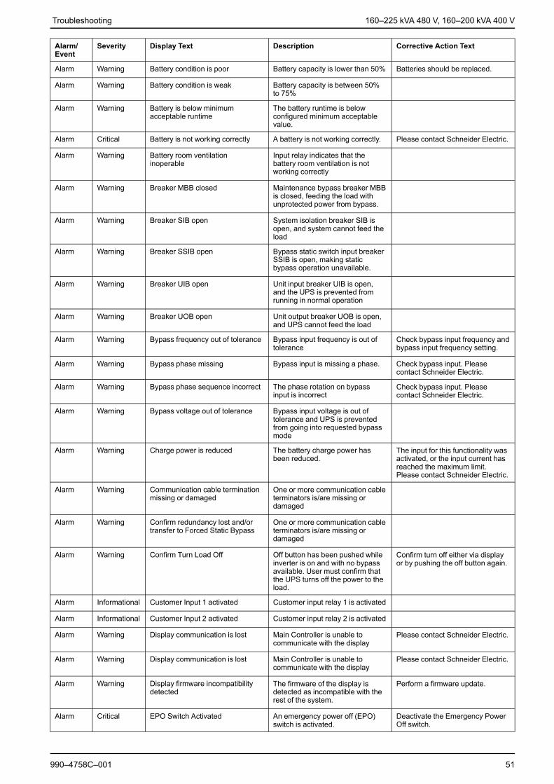
Alarm Messages
Alarm/Event
Severity Display Text Description Corrective Action Text
Alarm Warning Abnormal state at input contactzone A
An abnormal state exists forintegrated Environmental Monitorinput contact zone A
Please check the environment
Alarm Warning Abnormal state at input contactzone B
An abnormal state exists forintegrated Environmental Monitorinput contact zone B
Please check the environment
Alarm Warning Air Filter technical checkrecommended
The air filters need to be checkedas preventive maintenance isrecommended.
The Air Filters may need to bereplaced.
Alarm Warning Ambient temperature high Ambient temperature is high.
Alarm Warning Ambient temperature out oftolerance
The ambient temperature out oftolerance
Alarm Warning Batteries are discharging The load is drawing more powerthan the UPS can draw from theinput, causing the UPS to drawpower from the batteries.
Alarm Warning Battery breaker BB1 open Battery breaker BB1 is open
Alarm Warning Battery breaker BB2 open Battery breaker BB2 is open
Alarm Warning Battery capacity is below minimumacceptable level
The battery capacity is below theminimum acceptable valueaccording to UPS power rating.Risk of battery damage.
Change battery configuration and/or add larger capacity battery
Event Informational Battery breakers tripped To prevent the batteries deepdischarging, the battery breakershave been tripped by the system.
Close the battery breakersmanually.
50 990–4758C–001
Troubleshooting 160–225 kVA 480 V, 160–200 kVA 400 V
Alarm/Event
Severity Display Text Description Corrective Action Text
Alarm Warning Battery condition is poor Battery capacity is lower than 50% Batteries should be replaced.
Alarm Warning Battery condition is weak Battery capacity is between 50%to 75%
Alarm Warning Battery is below minimumacceptable runtime
The battery runtime is belowconfigured minimum acceptablevalue.
Alarm Critical Battery is not working correctly A battery is not working correctly. Please contact Schneider Electric.
Alarm Warning Battery room ventilationinoperable
Input relay indicates that thebattery room ventilation is notworking correctly
Alarm Warning Breaker MBB closed Maintenance bypass breaker MBBis closed, feeding the load withunprotected power from bypass.
Alarm Warning Breaker SIB open System isolation breaker SIB isopen, and system cannot feed theload
Alarm Warning Breaker SSIB open Bypass static switch input breakerSSIB is open, making staticbypass operation unavailable.
Alarm Warning Breaker UIB open Unit input breaker UIB is open,and the UPS is prevented fromrunning in normal operation
Alarm Warning Breaker UOB open Unit output breaker UOB is open,and UPS cannot feed the load
Alarm Warning Bypass frequency out of tolerance Bypass input frequency is out oftolerance
Check bypass input frequency andbypass input frequency setting.
Alarm Warning Bypass phase missing Bypass input is missing a phase. Check bypass input. Pleasecontact Schneider Electric.
Alarm Warning Bypass phase sequence incorrect The phase rotation on bypassinput is incorrect
Check bypass input. Pleasecontact Schneider Electric.
Alarm Warning Bypass voltage out of tolerance Bypass input voltage is out oftolerance and UPS is preventedfrom going into requested bypassmode
Alarm Warning Charge power is reduced The battery charge power hasbeen reduced.
The input for this functionality wasactivated, or the input current hasreached the maximum limit.Please contact Schneider Electric.
Alarm Warning Communication cable terminationmissing or damaged
One or more communication cableterminators is/are missing ordamaged
Alarm Warning Confirm redundancy lost and/ortransfer to Forced Static Bypass
One or more communication cableterminators is/are missing ordamaged
Alarm Warning Confirm Turn Load Off Off button has been pushed whileinverter is on and with no bypassavailable. User must confirm thatthe UPS turns off the power to theload.
Confirm turn off either via displayor by pushing the off button again.
Alarm Informational Customer Input 1 activated Customer input relay 1 is activated
Alarm Informational Customer Input 2 activated Customer input relay 2 is activated
Alarm Warning Display communication is lost Main Controller is unable tocommunicate with the display
Please contact Schneider Electric.
Alarm Warning Display communication is lost Main Controller is unable tocommunicate with the display
Please contact Schneider Electric.
Alarm Warning Display firmware incompatibilitydetected
The firmware of the display isdetected as incompatible with therest of the system.
Perform a firmware update.
Alarm Critical EPO Switch Activated An emergency power off (EPO)switch is activated.
Deactivate the Emergency PowerOff switch.
990–4758C–001 51

160–225 kVA 480 V, 160–200 kVA 400 V Troubleshooting
Alarm/Event
Severity Display Text Description Corrective Action Text
Alarm Warning External battery monitoringdetected fault
Input relay indicates externalbattery monitoring detected fault
Alarm Warning External sync frequency out oftolerance
External sync frequency is out oftolerance
Check external sync frequency.
Alarm Warning External sync phase missing External sync is missing a phase. Check External sync.
Alarm Warning External sync phase sequenceincorrect
The phase rotation on externalsync is incorrect
Please contact Schneider Electric.
Alarm Warning External sync temporarily disabled External sync has beentemporarily disabled because UPScannot lock and syncronize to theexternal sync source
Check external sync
Alarm Warning External sync voltage out oftolerance
External sync voltage is out oftolerance and UPS is preventedfrom going into external syncmode
Alarm Critical Fan inoperable UPS has one or more inoperablefans. Fan redundancy is lost
Alarm Critical Firmware update - Incorrect UPSoperation mode
The UPS is no longer in thecorrect operation mode duringfirmware update. Risk of loaddrop.
Transfer UPS to maintenancebypass.
Alarm Warning Firmware versions in parallel UPSunits are not identical
The firmware versions in parallelUPS units are not identical
Firmware update all UPS units inthe parallel system to the sameversion
Alarm Critical Flywheel inoperable Input relay indicates that theflywheel is not working correctly.
Alarm Critical General parallel system event The parallel system is notconfigured correctly or is notworking correctly
Please contact Schneider Electric.
Alarm Informational Genset is supplying the UPS Input relay indicates that a gensetis supplying the UPS
Alarm Warning Ground fault detected Input relay indicates that a groundfault has been detected.
Please contact Schneider Electric.
Alarm Warning High Battery Temperature Level The battery temperature is abovethe Alarm setting
Check the battery temperature. Ahigh temperature may decreasethe battery lifetime.
Alarm Informational High Efficiency Mode disabled High efficiency mode is disabledfrom an input relay
Alarm Warning High humidity threshold violationat remote sensor
A high humidity threshold violationexists for integrated EnvironmentalMonitor sensor
Please check the environment.
Alarm Warning High temperature thresholdviolation at remote sensor
A high temperature thresholdviolation exists for integratedEnvironmental Monitor sensor
Please check the environment.
Alarm Warning Input frequency out of tolerance Mains input frequency is out oftolerance
Check input frequency and inputfrequency setting.
Alarm Warning Input phase missing Input is missing a phase. Check input. Please contactSchneider Electric.
Alarm Warning Input phase sequence incorrect The phase rotation on input isincorrect
Check input. Please contactSchneider Electric.
Alarm Warning Input voltage out of tolerance Mains input voltage is out oftolerance
Alarm Warning Inverter is Off due to a request bythe user
The inverter is off due to a requestby the user
Alarm Warning Inverter output is not in phase withbypass input
The UPS inverter output is not inphase with the bypass input.
Alarm Warning Lost communication to remotesensor
Lost the local networkmanagement interface-to-integrated Environmental Monitor
Please check the environment.
52 990–4758C–001

Troubleshooting 160–225 kVA 480 V, 160–200 kVA 400 V
Alarm/Event
Severity Display Text Description Corrective Action Text
Alarm Warning Lost parallel redundancy The load exceeds limit for an N+xUPS in redundancy (x is theconfigurable parallel redundancy)
Reduce the load on the system.
Alarm Warning Low Battery Temperature Level The battery temperature is belowthe Alarm setting
Alarm Warning Low humidity threshold violation atremote sensor
A low humidity threshold violationexists for integrated EnvironmentalMonitor sensor
Please check the environment.
Alarm Warning Low temperature thresholdviolation at remote sensor
A low temperature thresholdviolation exists for integratedEnvironmental Monitor sensor
Please check the environment.
Alarm Warning Maximum humidity thresholdviolation at remote sensor
A maximum humidity thresholdviolation exists for integratedEnvironmental Monitor sensor
Please check the environment.
Alarm Warning Maximum temperature thresholdviolation at remote sensor
A maximum temperature thresholdviolation exists for integratedEnvironmental Monitor sensor
Please check the environment.
Alarm Warning Minimum humidity thresholdviolation at remote sensor
A minimum humidity thresholdviolation exists for integratedEnvironmental Monitor sensor
Please check the environment.
Alarm Warning Minimum temperature thresholdviolation at remote sensor
A minimum temperature thresholdviolation exists for integratedEnvironmental Monitor sensor
Please check the environment.
Alarm Warning Modular battery breaker open Modular battery breaker is open.
Alarm Warning Modular battery cabinet is notworking correctly
Modular battery cabinet is notworking correctly
Check battery cabinet. Pleasecontact Schneider Electric.
Alarm Warning NMC 1 firmware incompatibilitydetected
The firmware of the NMC in SmartSlot 1 is detected as incompatiblewith the rest of the system.
Perform a firmware update.
Alarm Warning NMC 2 firmware incompatibilitydetected
The firmware of the NMC in SmartSlot 2 is detected as incompatiblewith the rest of the system.
Perform a firmware update.
Alarm Warning Not enough UPS units ready toturn on inverter
One or more parallel UPS unitshave been requested to turn oninverter, but not enough UPS unitsare ready for system to enterinverter on operation.
Turn on inverter of more UPS unitsand/or check the setting "MinimumNumber of UPS Required toSupply Load".
Alarm Warning Output frequency out of tolerance Output frequency is out oftolerance
Check output frequency andoutput frequency setting.
Alarm Warning Output voltage out of tolerance The output voltage is out oftolerance
Alarm Warning Overload on UPS due to highambient temperature
The load exceeds the ratedcapacity when running with highambient temperature.
Reduce load on system or ambienttemperature.
Alarm Warning Overload or short circuit on UPS Reduce load on system or checkfor output short circuit
The load exceeds 100% of ratedcapacity or there is a short circuiton the output.
Alarm Warning Parallel communication lost onPBUS cable 1
PBUS cable 1 may be damaged Replace parallel Cable 1.
Alarm Warning Parallel communication lost onPBUS cable 2
PBUS cable 2 may be damaged Replace parallel Cable 2.
Alarm Warning Parallel mixed operation mode One or more parallel UPS unitsare operating in battery operation,while others are operating innormal operation
Alarm Warning Parallel unit not present Main Controller is unable tocommunicate with parallel UPS X.The UPS might have beenpowered down or communicationcables may be damaged
Alarm Critical Restricted air flow Restricted air flow. This could be caused by a cloggedair filter or other obstacle blockingair flow.
990–4758C–001 53
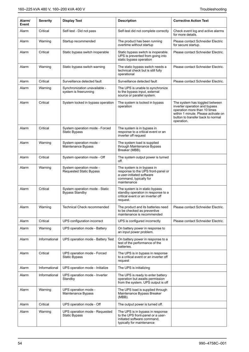
160–225 kVA 480 V, 160–200 kVA 400 V Troubleshooting
Alarm/Event
Severity Display Text Description Corrective Action Text
Alarm Critical Self-test - Did not pass Self-test did not complete correctly Check event log and active alarmsfor more details.
Alarm Warning Startup recommended The product has been runningovertime without startup
Please contact Schneider Electricfor secure startup.
Alarm Critical Static bypass switch inoperable Static bypass switch is inoperable.UPS is prevented from going intostatic bypass operation
Please contact Schneider Electric.
Alarm Warning Static bypass switch warning The static bypass switch needs atechnical check but is still fullyoperational
Please contact Schneider Electric.
Alarm Critical Surveillance detected fault Surveillance detected fault Please contact Schneider Electric.
Alarm Warning Synchronization unavailable -system is freerunning
The UPS is unable to synchronizeto the bypass input, externalsource or parallel system.
Alarm Critical System locked in bypass operation The system is locked in bypassoperation
The system has toggled betweeninverter operation and bypassoperation more than 10 timeswithin 1 minute. Please activate onbutton to transfer back to normaloperation.
Alarm Critical System operation mode - ForcedStatic Bypass
The system is in bypass inresponse to a critical event or aninverter off request
Alarm Warning System operation mode -Maintenance Bypass
The system load is suppliedthrough Maintenance BypassBreaker (MBB).
Alarm Critical System operation mode - Off The system output power is turnedoff.
Alarm Warning System operation mode -Requested Static Bypass
The system is in bypass inresponse to the UPS front-panel ora user-initiated softwarecommand, typically formaintenance
Alarm Critical System operation mode - StaticBypass Standby
The system is in static bypassstandby operation in response to acritical event or an inverter offrequest.
Alarm Warning Technical Check recommended The product and its batteries needto be checked as preventivemaintenance is recommended
Please contact Schneider Electric.
Alarm Critical UPS configuration incorrect UPS is configured incorrectly Please contact Schneider Electric.
Alarm Warning UPS operation mode - Battery On battery power in response toan input power problem.
Alarm Informational UPS operation mode - Battery Test On battery power in response to atest of the performance of thebatteries.
Alarm Critical UPS operation mode - ForcedStatic Bypass
The UPS is in bypass in responseto a critical event or an inverter offrequest
Alarm Informational UPS operation mode - Initialize The UPS is initializing
Alarm Informational UPS operation mode - InverterStandby
The UPS is ready to enter batteryoperation but awaits permissionfrom the system. UPS output is off
Alarm Warning UPS operation mode -Maintenance Bypass
The UPS load is supplied throughMaintenance Bypass Breaker(MBB).
Alarm Critical UPS operation mode - Off The output power is turned off.
Alarm Warning UPS operation mode - RequestedStatic Bypass
The UPS is in bypass in responseto the UPS front-panel or a user-initiated software command,typically for maintenance
54 990–4758C–001

Troubleshooting 160–225 kVA 480 V, 160–200 kVA 400 V
Alarm/Event
Severity Display Text Description Corrective Action Text
Alarm
Warning UPS operation mode - StaticBypass Standby
The UPS is ready to enter staticbypass but awaits permission fromthe system. UPS output is off
Alarm
Critical UPS settings reset to default Unit settings has been reset todefault. The UPS is locked in offoperation until settings areconfirmed.
Please contact Schneider Electric.
Alarm Warning Warranty expiring soon The product is reaching the end ofwarranty
Please contact Schneider Electric.
TestsThe UPS system can perform the following tests to ensure correct performance ofthe system:• Battery Test• Runtime Calibration• Annunciators• Display Calibration
Perform a Battery Test
Prerequisites:• The batteries must be more than 50% charged.• The runtime available must be more than 4 minutes.• The operation mode must be normal operation, ECOnversion, or ECO mode.• The system operation mode must be normal, ECOnversion, or ECO mode.This feature performs a number of tests on the batteries, such as fuse-blowncheck, weak battery detection. The test will discharge the battery, and use about10% of the total capacity. Meaning if you have 10 minutes of runtime, the test willrun for 1 minute. The Battery Test can be set up to run automatically in differenttime intervals (from weekly and up to once a year).
1. From the home screen on the display select Tests > Battery Test.2. Tap the Start Battery Self-Test button.
NOTE: If you wish to manually stop the battery self-test, tap the Abort BatterySelf-Test button.
Perform a Runtime Calibration
This feature is used for calibrating the estimated remaining battery runtime value.In this test the UPS transfers to battery operation and the batteries are dischargedto the low DC warning level. Based on the elapsed time and information about theload, the battery capacity can be calculated and the estimated runtime calibrated.
Schneider Electric recommends performing battery runtime calibration at start-up,when batteries are replaced, or when changes are made to the battery cabinets.
990–4758C–001 55

160–225 kVA 480 V, 160–200 kVA 400 V Troubleshooting
NOTICERISK OF EQUIPMENT DAMAGE• During a runtime calibration the batteries will be at a very low level and
therefore not capable of supporting your system load in case of a input powerfailure.
• Batteries will be discharged to 10% capacity and this will result in a lowbattery runtime after the calibration.
• Repeated battery testing or calibration can affect the lifetime of the battery.Failure to follow these instructions can result in equipment damage.
Prerequisites:• Batteries must be 100% charged.• The load percentage must be at least 10% and must not change more than
20% during test.• The bypass supply must be available.• The operation mode must be normal operation, ECOnversion, or ECO mode.• The system operation mode must be inverter, ECOnversion, or ECO mode.
1. From the home screen on the display select Tests > Runtime Calibration.2. Tap the Start Runtime Calibration button.
NOTE: If you wish to manually stop the runtime calibration, tap the AbortRuntime Calibration button.
Perform an Annunciators Test
1. From the home screen on the display select Tests > Annunciators.2. Tap the Start button to initiate the test.
During the annunciators test the LEDs on the display and the mimic diagramand the audible alarm are tested.
Calibrate the Display
From the home screen on the display select Tests > Display Calibration and thenselect the calibration you want to perform.• Calibrate: Tests and adjusts the touch screen target sensitivity.• Calibration Check: Checks the calibration adjustments.
Determine if you need a Replacement PartTo determine if you need a replacement part, contact Schneider Electric and followthe procedure below so that the representative can assist you promptly:
1. In the event of an alarm condition, scroll through the alarm lists, record theinformation, and provide it to the representative.
2. Write down the serial number of the unit so that you will have it easilyaccessible when you contact Schneider Electric.
3. If possible, call Schneider Electric from a telephone that is within reach of thedisplay so that you can gather and report additional information to therepresentative.
56 990–4758C–001
Troubleshooting 160–225 kVA 480 V, 160–200 kVA 400 V
4. Be prepared to provide a detailed description of the problem. A representativewill help you solve the problem over the telephone, if possible, or will assign areturn material authorization (RMA) number to you. If a module is returned toSchneider Electric, this RMA number must be clearly printed on the outside ofthe package.
5. If the unit is within the warranty period and has been started up by SchneiderElectric, repairs or replacements will be performed free of charge. If it is notwithin the warranty period, there will be a charge.
6. If the unit is covered by a Schneider Electric service contract, have the contractavailable to provide information to the representative.
Find the UPS Serial Number
1. From the home screen on the display interface select About > UPS.2. Note down the serial number and have it ready for customer support.
NOTE: If the display is not available, the serial number can also be found on alabel in each specific cabinet.
Return Parts to Schneider ElectricCall Schneider Electric to obtain an RMA number.
To return an inoperable part to Schneider Electric, pack the module in the originalshipping materials, and return it by insured, prepaid carrier. The customer supportrepresentative will provide the destination address. If you no longer have theoriginal shipping materials, ask the representative about obtaining a new set. Packthe module properly to avoid damage in transit. Never use styrofoam beads orother loose packaging materials when shipping a module. The module may settlein transit and become damaged. Enclose a letter in the package with your name,RMA number, address, a copy of the sales receipt, description of the problem, aphone number, and a confirmation for payment (if necessary).
NOTE: Damages sustained in transit are not covered under warranty.
990–4758C–001 57


Schneider Electric35 rue Joseph Monier92500 Rueil MalmaisonFrance
+ 33 (0) 1 41 29 70 00
www.schneider-electric.com
As standards, specifications, and design change from time to time,please ask for confirmation of the information given in this publication.
© 2013 – 2016 Schneider Electric. All rights reserved.
990–4758C–001


![CICADA - USENIX · 1 vm 2 vm 3 vm 4 vm 5vm 6 vm 7 vm 8 vm 9 vm 2 vm 3 vm 4 vm 5 vm 6 vm 7 vm 8 vm 9 vm 1 rigid application (similar to VOC [1]) vm 1 vm 2 vm 3 vm 4 vm 5vm 6 vm 7 vm](https://img.pdfslide.us/doc/110x75/5f3ade2be7477529602b0cb3/cicada-usenix-1-vm-2-vm-3-vm-4-vm-5vm-6-vm-7-vm-8-vm-9-vm-2-vm-3-vm-4-vm-5-vm.jpg)