Embed Size (px)
Citation preview
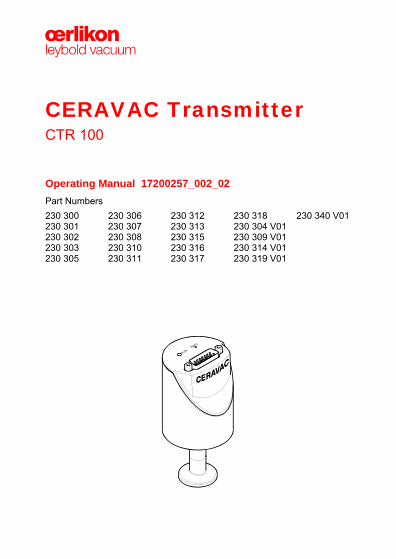
CERAVAC Transmitter CTR 100
Operating Manual 17200257_002_02 Part Numbers 230 300 230 301 230 302 230 303 230 305
230 306 230 307 230 308 230 310 230 311
230 312 230 313 230 315 230 316 230 317
230 318 230 304 V01 230 309 V01 230 314 V01 230 319 V01
230 340 V01
2 17200257_002_02 - (2011-03) - © Oerlikon Leybold Vacuum
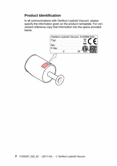
Product Identification In all communications with Oerlikon Leybold Vacuum, please specify the information given on the product nameplate. For con-venient reference copy that information into the space provided below.
Typ:
No: F-No: V W
Oerlikon Leybold Vacuum, D-50968 Köln
17200257_002_02 - (2011-03) - © Oerlikon Leybold Vacuum 3
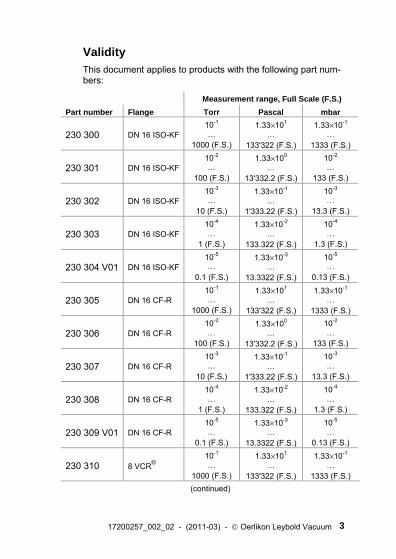
Validity This document applies to products with the following part num-bers:
Measurement range, Full Scale (F.S.) Part number Flange Torr Pascal mbar
230 300 DN 16 ISO-KF10-1 …
1000 (F.S.)
1.33×101 …
133'322 (F.S.)
1.33×10⁻¹ …
1333 (F.S.)
230 301 DN 16 ISO-KF10-2 …
100 (F.S.)
1.33×100 …
13'332.2 (F.S.)
10-2 …
133 (F.S.)
230 302 DN 16 ISO-KF10-3 …
10 (F.S.)
1.33×10⁻¹ …
1'333.22 (F.S.)
10-3 …
13.3 (F.S.)
230 303 DN 16 ISO-KF10-4 …
1 (F.S.)
1.33×10⁻² …
133.322 (F.S.)
10-4 …
1.3 (F.S.)
230 304 V01 DN 16 ISO-KF10-5 …
0.1 (F.S.)
1.33×10⁻³ …
13.3322 (F.S.)
10-5 …
0.13 (F.S.)
230 305 DN 16 CF-R 10-1 …
1000 (F.S.)
1.33×101 …
133'322 (F.S.)
1.33×10⁻¹ …
1333 (F.S.)
230 306 DN 16 CF-R 10-2 …
100 (F.S.)
1.33×100 …
13'332.2 (F.S.)
10-2 …
133 (F.S.)
230 307 DN 16 CF-R 10-3 …
10 (F.S.)
1.33×10⁻¹ …
1'333.22 (F.S.)
10-3 …
13.3 (F.S.)
230 308 DN 16 CF-R 10-4 …
1 (F.S.)
1.33×10⁻² …
133.322 (F.S.)
10-4 …
1.3 (F.S.)
230 309 V01 DN 16 CF-R 10-5 …
0.1 (F.S.)
1.33×10⁻³ …
13.3322 (F.S.)
10-5 …
0.13 (F.S.)
230 310 8 VCR® 10-1 …
1000 (F.S.)
1.33×101 …
133'322 (F.S.)
1.33×10⁻¹ …
1333 (F.S.) (continued)
4 17200257_002_02 - (2011-03) - © Oerlikon Leybold Vacuum
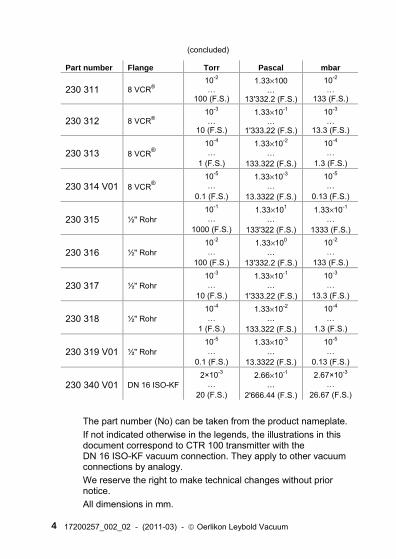
(concluded)
Part number Flange Torr Pascal mbar
230 311 8 VCR® 10-2 …
100 (F.S.)
1.33×100 …
13'332.2 (F.S.)
10-2 …
133 (F.S.)
230 312 8 VCR® 10-3 …
10 (F.S.)
1.33×10⁻¹ …
1'333.22 (F.S.)
10-3 …
13.3 (F.S.)
230 313 8 VCR® 10-4 …
1 (F.S.)
1.33×10⁻² …
133.322 (F.S.)
10-4 …
1.3 (F.S.)
230 314 V01 8 VCR® 10-5 …
0.1 (F.S.)
1.33×10⁻³ …
13.3322 (F.S.)
10-5 …
0.13 (F.S.)
230 315 ½" Rohr 10-1 …
1000 (F.S.)
1.33×101 …
133'322 (F.S.)
1.33×10⁻¹ …
1333 (F.S.)
230 316 ½" Rohr 10-2 …
100 (F.S.)
1.33×100 …
13'332.2 (F.S.)
10-2 …
133 (F.S.)
230 317 ½" Rohr 10-3 …
10 (F.S.)
1.33×10⁻¹ …
1'333.22 (F.S.)
10-3 …
13.3 (F.S.)
230 318 ½" Rohr 10-4 …
1 (F.S.)
1.33×10⁻² …
133.322 (F.S.)
10-4 …
1.3 (F.S.)
230 319 V01 ½" Rohr 10-5 …
0.1 (F.S.)
1.33×10⁻³ …
13.3322 (F.S.)
10-5 …
0.13 (F.S.)
230 340 V01 DN 16 ISO-KF2×10-3
… 20 (F.S.)
2.66×10⁻¹ …
2'666.44 (F.S.)
2.67×10⁻³ …
26.67 (F.S.)
The part number (No) can be taken from the product nameplate. If not indicated otherwise in the legends, the illustrations in this document correspond to CTR 100 transmitter with the DN 16 ISO-KF vacuum connection. They apply to other vacuum connections by analogy. We reserve the right to make technical changes without prior notice. All dimensions in mm.
17200257_002_02 - (2011-03) - © Oerlikon Leybold Vacuum 5
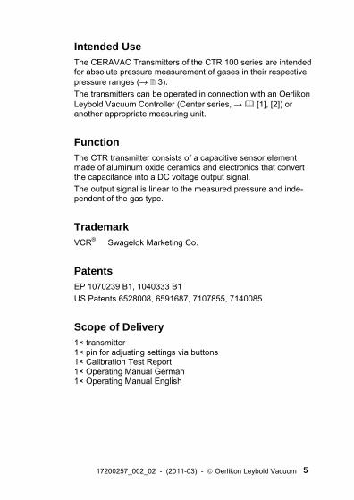
Intended Use The CERAVAC Transmitters of the CTR 100 series are intended for absolute pressure measurement of gases in their respective pressure ranges (→ 3). The transmitters can be operated in connection with an Oerlikon Leybold Vacuum Controller (Center series, → [1], [2]) or another appropriate measuring unit.
Function The CTR transmitter consists of a capacitive sensor element made of aluminum oxide ceramics and electronics that convert the capacitance into a DC voltage output signal. The output signal is linear to the measured pressure and inde-pendent of the gas type.
Trademark VCR® Swagelok Marketing Co.
Patents EP 1070239 B1, 1040333 B1 US Patents 6528008, 6591687, 7107855, 7140085
Scope of Delivery 1× transmitter 1× pin for adjusting settings via buttons 1× Calibration Test Report 1× Operating Manual German 1× Operating Manual English
6 17200257_002_02 - (2011-03) - © Oerlikon Leybold Vacuum
Contents
Product Identification 2 Validity 3 Intended Use 5 Function 5 Trademark 5 Patents 5 Scope of Delivery 5 1 Safety 7 1.1 Symbols Used 7 1.2 Personnel Qualifications 7 1.3 General Safety Instructions 8 1.4 Liability and Warranty 8 2 Technical Data 9 3 Installation 14 3.1 Vacuum Connection 14 3.2 Electrical Connection 17 4 Operation 19 4.1 Displays 19 4.2 Zeroing the Transmitter 19 4.3 Activating the Factory Setting (Factory Reset) 23 5 Deinstallation 24 6 Maintenance, Repair 25 7 Returning the Product 26 8 Disposal 27 9 Literature 28 ETL Certification 29 EC Declaration of Conformity 30
For cross-references within this document, the symbol (→ XY) is used, for cross-references to further documents, listed under literature, the symbol (→ [Z]).
17200257_002_02 - (2011-03) - © Oerlikon Leybold Vacuum 7
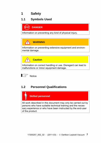
1 Safety 1.1 Symbols Used
DANGER
Information on preventing any kind of physical injury.
WARNING
Information on preventing extensive equipment and environ-mental damage.
Caution
Information on correct handling or use. Disregard can lead to malfunctions or minor equipment damage.
Notice
1.2 Personnel Qualifications
Skilled personnel
All work described in this document may only be carried out by persons who have suitable technical training and the neces-sary experience or who have been instructed by the end-user of the product.
8 17200257_002_02 - (2011-03) - © Oerlikon Leybold Vacuum
1.3 General Safety Instructions • Adhere to the applicable regulations and take the necessary
precautions for the process media used. Consider possible reactions with the product materials.
• Adhere to the applicable regulations and take the necessary precautions for all work you are going to do and consider the safety instructions in this document.
• Before beginning to work, find out whether any vacuum com-ponents are contaminated. Adhere to the relevant regulations and take the necessary precautions when handling contamin-ated parts.
Communicate the safety instructions to all other users.
1.4 Liability and Warranty Oerlikon Leybold Vacuum assumes no liability and the warranty becomes null and void if the end-user or third parties • disregard the information in this document • use the product in a non-conforming manner • make any kind of interventions (modifications, alterations etc.)
on the product • use the product with accessories not listed in the product
documentation.
The end-user assumes the responsibility in conjunction with the process media used. Transmitter failures due to contamination or wear and tear are not covered by the warranty.
17200257_002_02 - (2011-03) - © Oerlikon Leybold Vacuum 9
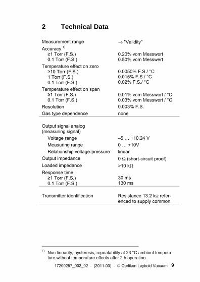
2 Technical Data
Measurement range → "Validity" Accuracy 1)
≥1 Torr (F.S.) 0.1 Torr (F.S.)
0.20% vom Messwert 0.50% vom Messwert
Temperature effect on zero ≥10 Torr (F.S.) 1 Torr (F.S.) 0.1 Torr (F.S.)
0.0050% F.S./ °C 0.015% F.S./ °C 0.02% F.S./ °C
Temperature effect on span ≥1 Torr (F.S.) 0.1 Torr (F.S.)
0.01% vom Messwert / °C 0.03% vom Messwert / °C
Resolution 0.003% F.S. Gas type dependence none Output signal analog (measuring signal)
Voltage range –5 … +10.24 V Measuring range 0 … +10V Relationship voltage-pressure linear
Output impedance 0 Ω (short-circuit proof) Loaded impedance >10 kΩ Response time
≥1 Torr (F.S.) 0.1 Torr (F.S.)
30 ms 130 ms
Transmitter identification Resistance 13.2 kΩ refer-
enced to supply common
1) Non-linearity, hysteresis, repeatability at 23 °C ambient tempera-
ture without temperature effects after 2 h operation.
10 17200257_002_02 - (2011-03) - © Oerlikon Leybold Vacuum
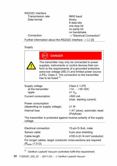
RS232C interface Transmission rate Data format Connection
9600 baud binary 8 data bits one stop bit no parity bit no handshake → "Electrical Connection"
Further information about the RS232C interface → [3] Supply
DANGER
The transmitter may only be connected to power supplies, instruments or control devices that con-form to the requirements of a grounded protective extra-low voltage (SELV) and limited power source (LPS), Class 2. The connection to the transmitter has to be fused 2).
Supply voltage at the transmitter ripple
Class 2 / LPS +14 … +30 VDC ≤1 Vpp
Current consumption <500 mA (max. starting current)
Power consumption (depending on supply voltage)
≤1 W
Internal fuse 1 AT (slow), automatic reset (Polyfuse)
The transmitter is protected against reverse polarity of the supply voltage. Electrical connection 15-pin D-Sub, male Sensor cable 5-pin plus shielding Cable length ≤100 m (0.14 mm² conductor) For longer cables, larger conductor cross-sections are required (Rcable ≤1.0 Ω). 2) Oerlikon Leybold Vacuum controllers fulfill this requirement.
17200257_002_02 - (2011-03) - © Oerlikon Leybold Vacuum 11
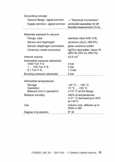
Grounding concept
Vacuum flange - signal common → "Electrical Connection" Supply common - signal common conducted separately; for dif-
ferential measurement (10 Ω) Materials exposed to vacuum
Flange, tube Sensor and diaphragm Sensor–diaphragm connection Ceramics–metal connection
stainless steel AISI 316L ceramics (Al2O3 ≥99.5%) glass ceramics solder AgTiCu hard solder, Vacon 70 (28% Ni, 23% Co, 49% Fe)
Internal volume ≤3.6 cm3 Admissible pressure (absolute)
1000 Torr F.S 1 … 100 Torr F.S. 0.1 Torr F.S.
3 bar 2 bar 1.3 bar
Bursting pressure (absolute) 5 bar Admissible temperatures
Storage Operation Bakeout (not in operation)
–40 °C … +65 °C +5 °C … +50 °C ≤110 °C at the flange
Relative humidity ≤80% at temperatures ≤+31 °C decreasing to 50% at +40°C
Use indoors only, altitude up to 2000 m NN
Degree of protection IP 30
12 17200257_002_02 - (2011-03) - © Oerlikon Leybold Vacuum
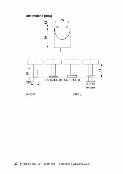
Dimensions [mm]
8 VCRfemale
DN 16 ISO-KF
55
69
DN 16 CF-R
44
26
3.8
OD½"
Weight ≤370 g
17200257_002_02 - (2011-03) - © Oerlikon Leybold Vacuum 13
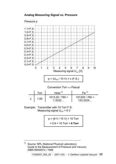
Analog Measuring Signal vs. Pressure
1 2 3 4 5 6 7 8 9 100
0.9×F.S.
0.5×F.S.0.6×F.S.
1.0×F.S.
0.7×F.S.0.8×F.S.
0.1×F.S.0.2×F.S.0.3×F.S.0.4×F.S.
1.1×F.S.
Pressure p
Measuring signal Uout [V]
0.0×F.S.
p = (Uout / 10 V) × c (F.S.)
Conversion Torr ↔ Pascal
Torr mbar 3) Pa 3)
c 1.00 1013.25 / 760 = 1.3332…
101325 / 760 = 133.3224…
Example: Transmitter with 10 Torr F.S.
Measuring signal Uout = 6 V
p = (6 V / 10 V) × 10 Torr
= 0.6 × 10 Torr = 6 Torr
3) Source: NPL (National Physical Laboratory)
Guide to the Measurement of Pressure and Vacuum, ISBN 0904457x / 1998
14 17200257_002_02 - (2011-03) - © Oerlikon Leybold Vacuum
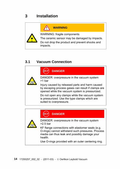
3 Installation
WARNING
WARNING: fragile components The ceramic sensor may be damaged by impacts. Do not drop the product and prevent shocks and impacts.
3.1 Vacuum Connection
DANGER
DANGER: overpressure in the vacuum system >1 bar Injury caused by released parts and harm caused by escaping process gases can result if clamps are opened while the vacuum system is pressurized. Do not open any clamps while the vacuum system is pressurized. Use the type clamps which are suited to overpressure.
DANGER
DANGER: overpressure in the vacuum system >2.5 bar KF flange connections with elastomer seals (e.g. O-rings) cannot withstand such pressures. Process media can thus leak and possibly damage your health. Use O-rings provided with an outer centering ring.
17200257_002_02 - (2011-03) - © Oerlikon Leybold Vacuum 15
DANGER
DANGER: protective ground Products that are not correctly connected to ground can be extremely hazardous in the event of a fault. Electrically connect the transmitter to the grounded vacuum chamber. This connection must conform to the requirements of a protective connection ac-cording to EN 61010: • CF and VCR flanges fulfill this requirement. • For transmitters with a KF flange, use a conduc-
tive metallic clamping ring. • For transmitters with a ½" tube, take appropriate
measures to fulfill this requirement.
Caution
Caution: vacuum component Dirt and damages impair the function of the vac-uum component. When handling vacuum components, take appro-priate measures to ensure cleanliness and prevent damages.
Caution
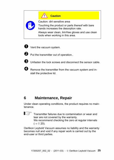
Caution: dirt sensitive area Touching the product or parts thereof with bare hands increases the desorption rate. Always wear clean, lint-free gloves and use clean tools when working in this area.
16 17200257_002_02 - (2011-03) - © Oerlikon Leybold Vacuum
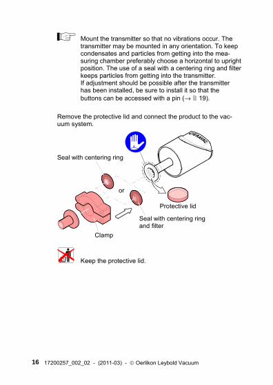
Mount the transmitter so that no vibrations occur. The transmitter may be mounted in any orientation. To keep condensates and particles from getting into the mea-suring chamber preferably choose a horizontal to upright position. The use of a seal with a centering ring and filter keeps particles from getting into the transmitter. If adjustment should be possible after the transmitter has been installed, be sure to install it so that the buttons can be accessed with a pin (→ 19).
Remove the protective lid and connect the product to the vac-uum system.
Clamp
Seal with centering ring
or
Seal with centering ringand filter
Protective lid
Keep the protective lid.
17200257_002_02 - (2011-03) - © Oerlikon Leybold Vacuum 17
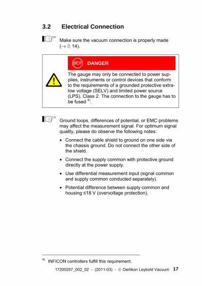
3.2 Electrical Connection
Make sure the vacuum connection is properly made (→ 14).
DANGER
The gauge may only be connected to power sup-plies, instruments or control devices that conform to the requirements of a grounded protective extra-low voltage (SELV) and limited power source (LPS), Class 2. The connection to the gauge has to be fused 4).
Ground loops, differences of potential, or EMC problems may affect the measurement signal. For optimum signal quality, please do observe the following notes:
• Connect the cable shield to ground on one side via the chassis ground. Do not connect the other side of the shield.
• Connect the supply common with protective ground directly at the power supply.
• Use differential measurement input (signal common and supply common conducted separately).
• Potential difference between supply common and housing ≤18 V (overvoltage protection).
4) INFICON controllers fulfill this requirement.
18 17200257_002_02 - (2011-03) - © Oerlikon Leybold Vacuum
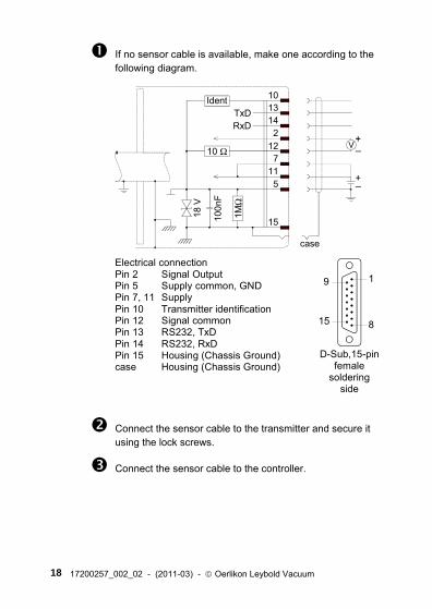
If no sensor cable is available, make one according to the following diagram.
Electrical connectionPin 2 Signal OutputPin 5 Supply common, GNDPin 7, 11 SupplyPin 10 Transmitter identificationPin 12 Signal commonPin 13 RS232, TxDPin 14 RS232, RxDPin 15 Housing (Chassis Ground)case Housing (Chassis Ground)
case
10Ident13142
TxDRxD
127
115
15100n
F
18 V
10 Ω
1MΩ
15 8
9 1
D-Sub,15-pinfemale
solderingside
Connect the sensor cable to the transmitter and secure it using the lock screws.
Connect the sensor cable to the controller.
17200257_002_02 - (2011-03) - © Oerlikon Leybold Vacuum 19
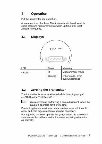
4 Operation Put the transmitter into operation.
A warm-up time of at least 15 minutes should be allowed; for exact pressure measurements a warm-up time of at least 2 hours is required.
4.1 Displays
RUN ZERO
LED State Meaning
<RUN> lit Measurement mode blinking Other mode, error,
over/underrange
4.2 Zeroing the Transmitter The transmitter is factory calibrated while "standing upright" (→ "Calibration Test Report").
We recommend performing a zero adjustment, when the gauge is operated for the first time.
Due to long time operation or contamination, a zero drift could occur and zero adjustment may become necessary. For adjusting the zero, operate the gauge under the same con-stant ambient conditions and in the same mounting orientation as normally.
20 17200257_002_02 - (2011-03) - © Oerlikon Leybold Vacuum
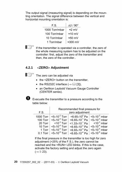
The output signal (measuring signal) is depending on the moun-ting orientation. The signal difference between the vertical and horizontal mounting orientation is:
F.S. ΔU / 90° 1000 Torr/mbar ≈2 mV
100 Torr/mbar ≈10 mV
10 Torr/mbar ≈50 mV
1 Torr/mbar ≈300 mV
If the transmitter is operated via a controller, the zero of the whole measuring system has to be adjusted on the controller: first, adjust the zero of the transmitter and then, the zero of the controller..
4.2.1 <ZERO> Adjustment
The zero can be adjusted via • the <ZERO> button on the transmitter, • the RS232C interface (→ [3]), • an Oerlikon Leybold Vacuum Gauge Controller
(CENTER series).
Evacuate the transmitter to a pressure according to the table below:
F.S. Recommended final pressure for
zero adjustment 1000 Torr 100 Torr 20 Torr 10 Torr 1 Torr
0.1 Torr
<5×10⁻² Torr<5×10⁻³ Torr
<10-3 Torr<5×10⁻⁴ Torr<5×10⁻⁵ Torr<5×10⁻⁶ Torr
<6.65×100 Pa <6.65×10⁻¹ Pa <1.33×10⁻¹ Pa <6.65×10⁻² Pa <6.65×10⁻³ Pa <6.65×10⁻⁴ Pa
<5×10⁻² mbar<5×10⁻³ mbar
<10-3 mbar<5×10⁻⁴ mbar<5×10⁻⁵ mbar<5×10⁻⁶ mbar
If the final pressure in the transmitter is too high for zero adjustment (>25% of the F.S.), the zero cannot be reached and the <RUN> LED blinks. If this is the case, activate the factory setting and adjust the zero again (→ 23).
17200257_002_02 - (2011-03) - © Oerlikon Leybold Vacuum 21
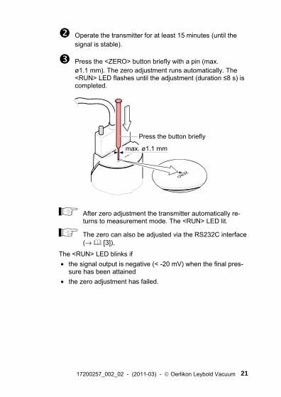
Operate the transmitter for at least 15 minutes (until the signal is stable).
Press the <ZERO> button briefly with a pin (max. ø1.1 mm). The zero adjustment runs automatically. The <RUN> LED flashes until the adjustment (duration ≤8 s) is completed.
Press the button briefly
max. ø1.1 mm
After zero adjustment the transmitter automatically re-turns to measurement mode. The <RUN> LED lit.
The zero can also be adjusted via the RS232C interface (→ [3]).
The <RUN> LED blinks if • the signal output is negative (< -20 mV) when the final pres-
sure has been attained • the zero adjustment has failed.
22 17200257_002_02 - (2011-03) - © Oerlikon Leybold Vacuum
4.2.2 <ZERO> Adjustment with Ramp Function The ramp function allows to adjust the zero at a known reference pressure within the measuring range of the transmitter.
It also permits to adjust an offset of the characteristic curve in order to • compensate for the offset of the measuring system or • obtain a slightly positive zero for a 0 … 10 V AD-converter.
The offset should not exceed 2% of the F.S. (+200 mV). At a higher positive offset, the upper limit of the measuring range is passed.
Recommended procedure for adjusting the offset of a measuring system: → Notice 20.
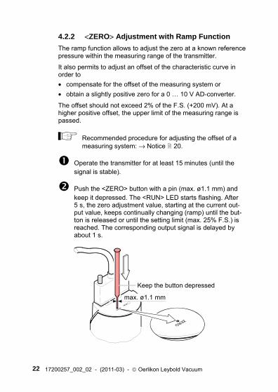
Operate the transmitter for at least 15 minutes (until the signal is stable).
Push the <ZERO> button with a pin (max. ø1.1 mm) and keep it depressed. The <RUN> LED starts flashing. After 5 s, the zero adjustment value, starting at the current out-put value, keeps continually changing (ramp) until the but-ton is released or until the setting limit (max. 25% F.S.) is reached. The corresponding output signal is delayed by about 1 s.
Keep the button depressed
max. ø1.1 mm
17200257_002_02 - (2011-03) - © Oerlikon Leybold Vacuum 23
Push the <ZERO> button again:
Fine adjustment within 0...3 s:
the zero adjustment value changes by one unit (push <ZERO> button in intervals of 1 s)
Change of direction within 3...5 s:
the zero adjustment changes its direction (the blinking frequency of the <RUN> LED changes briefly)
If the <ZERO> button is released for more than 5 s, the transmitter returns to the measurement mode.
The zero with ramp function can also be adjusted via the RS232C interface (→ [3]).
The <RUN> LED blinks if the signal output is negative (< -20 mV).
4.3 Activating the Factory Setting (Factory Reset)
All user defined parameters (e.g. zero, filter) are restored to their default values.
Loading the default parameters:
But the transmitter out of operation.
Keep the <ZERO> button depressed for at least 5 s while the transmitter is being put into operation (Power ON).
24 17200257_002_02 - (2011-03) - © Oerlikon Leybold Vacuum
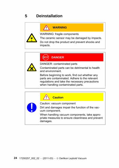
5 Deinstallation
WARNING
WARNING: fragile components The ceramic sensor may be damaged by impacts. Do not drop the product and prevent shocks and impacts.
DANGER
DANGER: contaminated parts Contaminated parts can be detrimental to health and environment. Before beginning to work, find out whether any parts are contaminated. Adhere to the relevant regulations and take the necessary precautions when handling contaminated parts.
Caution
Caution: vacuum component Dirt and damages impair the function of the vac-uum component. When handling vacuum components, take appro-priate measures to ensure cleanliness and prevent damages.
17200257_002_02 - (2011-03) - © Oerlikon Leybold Vacuum 25
Caution
Caution: dirt sensitive area Touching the product or parts thereof with bare hands increases the desorption rate. Always wear clean, lint-free gloves and use clean tools when working in this area.
Vent the vacuum system.
Put the transmitter out of operation..
Unfasten the lock screws and disconnect the sensor cable.
Remove the transmitter from the vacuum system and in-stall the protective lid.
6 Maintenance, Repair Under clean operating conditions, the product requires no main-tenance.
Transmitter failures due to contamination or wear and tear are not covered by the warranty. We recommend checking the zero at regular intervals (→ 20).
Oerlikon Leybold Vacuum assumes no liability and the warranty becomes null and void if any repair work is carried out by the end-user or third parties.
26 17200257_002_02 - (2011-03) - © Oerlikon Leybold Vacuum
7 Returning the Product
WARNING
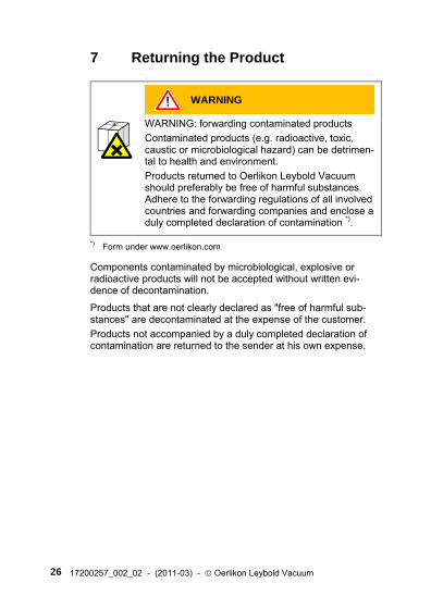
WARNING: forwarding contaminated products Contaminated products (e.g. radioactive, toxic, caustic or microbiological hazard) can be detrimen-tal to health and environment. Products returned to Oerlikon Leybold Vacuum should preferably be free of harmful substances. Adhere to the forwarding regulations of all involved countries and forwarding companies and enclose a duly completed declaration of contamination *).
*) Form under www.oerlikon.com
Components contaminated by microbiological, explosive or radioactive products will not be accepted without written evi-dence of decontamination.
Products that are not clearly declared as "free of harmful sub-stances" are decontaminated at the expense of the customer. Products not accompanied by a duly completed declaration of contamination are returned to the sender at his own expense.
17200257_002_02 - (2011-03) - © Oerlikon Leybold Vacuum 27
8 Disposal
DANGER
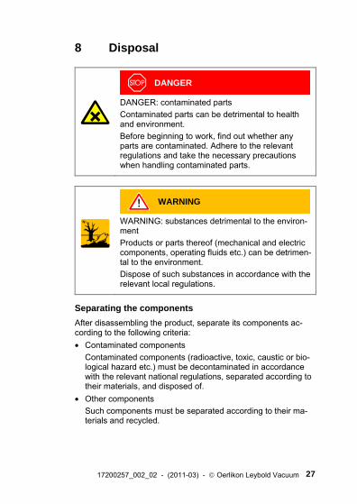
DANGER: contaminated parts Contaminated parts can be detrimental to health and environment. Before beginning to work, find out whether any parts are contaminated. Adhere to the relevant regulations and take the necessary precautions when handling contaminated parts.
N
WARNING
WARNING: substances detrimental to the environ-ment Products or parts thereof (mechanical and electric components, operating fluids etc.) can be detrimen-tal to the environment. Dispose of such substances in accordance with the relevant local regulations.
Separating the components After disassembling the product, separate its components ac-cording to the following criteria: • Contaminated components
Contaminated components (radioactive, toxic, caustic or bio-logical hazard etc.) must be decontaminated in accordance with the relevant national regulations, separated according to their materials, and disposed of.
• Other components Such components must be separated according to their ma-terials and recycled.
28 17200257_002_02 - (2011-03) - © Oerlikon Leybold Vacuum
9 Literature
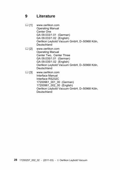
[1] www.oerlikon.com Operating Manual Center One GA 09.033/1.01 (German) GA 09.033/1.02 (English) Oerlikon Leybold Vacuum GmbH, D–50968 Köln, Deutschland
[2] www.oerlikon.com Operating Manual Center Two, Center Three GA 09.035/1.01 (German) GA 09.035/1.02 (English) Oerlikon Leybold Vacuum GmbH, D–50968 Köln, Deutschland
[3] www.oerlikon.com Interface Manual Interface RS232C 17200961_001_00 (German) 17200961_002_00 (English) Oerlikon Leybold Vacuum GmbH, D–50968 Köln, Deutschland
17200257_002_02 - (2011-03) - © Oerlikon Leybold Vacuum 29
ETL Certification
3103457
ETL LISTED The product CTR 100 complies with the requirements of the following Standards: UL 61010-1, Issued: 2004/07/12 Ed: 2 Rev: 2005/07/22 CAN/CSA C22.2#61010-1, Issued: 2004/07/12
30 17200257_002_02 - (2011-03) - © Oerlikon Leybold Vacuum
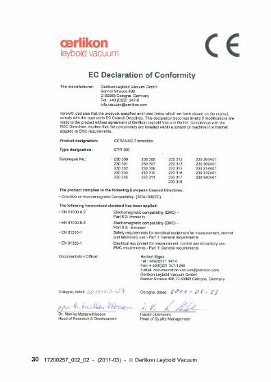
EC Declaration of Conformity

17200257_002_02 - (2011-03) - © Oerlikon Leybold Vacuum 31
Notes
Oerlikon Leybold Vacuum GmbH Bonner Straße 498 D-50968 Köln Tel.: +49-(0)221-347 1234 Fax: +49-(0)221-347 1245 [email protected]
www.oerl ikon.com
1720
0257
.00
2.02
Orig
inal
:
Ger
man
17
2002
57_0
01_0
2 (
2011
-03)


