Embed Size (px)
Citation preview
G8™ GPS OEM BoardReference Manual
For support on your G8 product, please contact your distributor.

ii
r by ut nd the n
t
ctive
Copyright NoticeCopyright © 1998 Magellan Corporation. All rights reserved. No part of this publication or the computer programs described in it may be reproduced, translated, stored in a retrieval system, or transmitted in any form oany means, electronic, mechanical photocopying, recording, or otherwise, withoprior written permission of Magellan. Your rights with regard to this publication athe computer programs are subject to the restrictions and limitations imposed bycopyright laws of the United States of America (“U.S.A.”) and/or the jurisdiction iwhich you are located.
For information on translations and distribution outside the U.S.A. please contacAshtech.
Printed in the United States of America.Part Number: 630181-01 Revision BJuly, 1998
Trademark NoticeG8, Evaluate, and the Ashtech logo are trademarks of Magellan Corp. All other product and brand names are trademarks or registered trademarks of their respeholders.
G8 OEM Board Reference Manual
Declaration of Conformity
(according to 47 CFR 2.1077)
Ashtech
1170 Kifer Road
Sunnyvale, California 94086
Tel:408-524-1400
declares that the product:
G-8 Evaluator
Model # 990285
complies with part 15 of the FFC Rules. Operation is subject to the following two conditions: (1) this device may not cause harmful interference, and (2) this device must accept any interference received, including interference that may cause undesired operation.
Ben DeovletSenior Components EngineerAshtech Sunnyvale, CaliforniaNovember 17, 1997
iii
iv
Declaration of Conformity(according to ISO/TEC Guide 22 and EN45014)
Ashtech 1170 Kifer Road
Sunnyvale, California 94086Tel:408-524-1400
declares that the product:G-8 Evaluator
Model # 990285(This declaration covers all options of the product)
to which this declaration relates, meets the essential health and safety requirements and is in conformity with the relevant EU Directives listed below:
EU EMC Directive 89/336/EEC 1993using the relevant section of the following EU standards and other normative documents: EMC: EN55022 1994 Class A
ENV50141 (1994)EN 61000-4-2 (1995)EN 61000-4-3 (1996)EN 61000-4-4 (1995)EN50082-1 (1992)
Supplementary Information:The product model listed above complies with the requirements of the Low Voltage Directive 73/23/EEC.
Ben DeovletSenior Components EngineerAshtech Sunnyvale, CaliforniaNovember 17, 1997
European Contact:Your local Ashtech Sales Office orAshtech Europe Limited, Blenheim Office Park, Long HanboroughOxfordshire OX8 8LN, EnglandTel: 44 993 883 533 FAX 44 993 883 977
G8 OEM Board Reference Manual
Table of Contents
Table of Co
Reliance F
undamentals
Chapter 1. General Information . . . . . . . . . . . . . . . . . . . . . . . . . . . . . . . . . . . . . . . 1
Overview . . . . . . . . . . . . . . . . . . . . . . . . . . . . . . . . . . . . . . . . . . . . . . . . . . . . . . . 1Functional Description . . . . . . . . . . . . . . . . . . . . . . . . . . . . . . . . . . . . . . . . . . . . 1Technical Specifications . . . . . . . . . . . . . . . . . . . . . . . . . . . . . . . . . . . . . . . . . . . 2Performance Specifications . . . . . . . . . . . . . . . . . . . . . . . . . . . . . . . . . . . . . . . . . 3Hardware Description . . . . . . . . . . . . . . . . . . . . . . . . . . . . . . . . . . . . . . . . . . . . . 4
Physical Configuration . . . . . . . . . . . . . . . . . . . . . . . . . . . . . . . . . . . . . . . . . 4Power/Input/Output Connections . . . . . . . . . . . . . . . . . . . . . . . . . . . . . . . . . . . . 6Interfaces to External Equipment . . . . . . . . . . . . . . . . . . . . . . . . . . . . . . . . . . . . 7Power Requirements . . . . . . . . . . . . . . . . . . . . . . . . . . . . . . . . . . . . . . . . . . . . . . 7Environmental Limitations . . . . . . . . . . . . . . . . . . . . . . . . . . . . . . . . . . . . . . . . . 7Antenna . . . . . . . . . . . . . . . . . . . . . . . . . . . . . . . . . . . . . . . . . . . . . . . . . . . . . . . . 8Radio Interference . . . . . . . . . . . . . . . . . . . . . . . . . . . . . . . . . . . . . . . . . . . . . . . . 9
Chapter 2. Getting Started . . . . . . . . . . . . . . . . . . . . . . . . . . . . . . . . . . . . . . . . . . 11
General . . . . . . . . . . . . . . . . . . . . . . . . . . . . . . . . . . . . . . . . . . . . . . . . . . . . . . . 11Quick Start . . . . . . . . . . . . . . . . . . . . . . . . . . . . . . . . . . . . . . . . . . . . . . . . . . . . . 11Connection Procedures . . . . . . . . . . . . . . . . . . . . . . . . . . . . . . . . . . . . . . . . . . . 11
Board . . . . . . . . . . . . . . . . . . . . . . . . . . . . . . . . . . . . . . . . . . . . . . . . . . . . . 11Serial Data Communication . . . . . . . . . . . . . . . . . . . . . . . . . . . . . . . . . . . . . . . 14
Communication Port Setup . . . . . . . . . . . . . . . . . . . . . . . . . . . . . . . . . . . . 14RTS/CTS Considerations . . . . . . . . . . . . . . . . . . . . . . . . . . . . . . . . . . . . . . 15Default Data Output . . . . . . . . . . . . . . . . . . . . . . . . . . . . . . . . . . . . . . . . . . 16Data Rate Limitations . . . . . . . . . . . . . . . . . . . . . . . . . . . . . . . . . . . . . . . . . 16
Initial Operating Instructions . . . . . . . . . . . . . . . . . . . . . . . . . . . . . . . . . . . . . . . 16
Chapter 3. Operation . . . . . . . . . . . . . . . . . . . . . . . . . . . . . . . . . . . . . . . . . . . . . . . 21
System Setup . . . . . . . . . . . . . . . . . . . . . . . . . . . . . . . . . . . . . . . . . . . . . . . . . . . 21Message Format . . . . . . . . . . . . . . . . . . . . . . . . . . . . . . . . . . . . . . . . . . . . . 21Input Messages to the G8 . . . . . . . . . . . . . . . . . . . . . . . . . . . . . . . . . . . . . . 21Output Messages From the G8 . . . . . . . . . . . . . . . . . . . . . . . . . . . . . . . . . . 22
Serial Port Configuration . . . . . . . . . . . . . . . . . . . . . . . . . . . . . . . . . . . . . . . . . . 22Antenna Connection . . . . . . . . . . . . . . . . . . . . . . . . . . . . . . . . . . . . . . . . . . . . . 22Satellite Search Algorithm . . . . . . . . . . . . . . . . . . . . . . . . . . . . . . . . . . . . . . . . 23Parameter Settings and Status . . . . . . . . . . . . . . . . . . . . . . . . . . . . . . . . . . . . . . 23
Saving New Parameter Settings . . . . . . . . . . . . . . . . . . . . . . . . . . . . . . . . . 25Position Modes . . . . . . . . . . . . . . . . . . . . . . . . . . . . . . . . . . . . . . . . . . . . . . 25Altitude Hold Definition . . . . . . . . . . . . . . . . . . . . . . . . . . . . . . . . . . . . . . 26
ntents v
vi
Antenna Position Setting . . . . . . . . . . . . . . . . . . . . . . . . . . . . . . . . . . . . . . 26NMEA Outputs . . . . . . . . . . . . . . . . . . . . . . . . . . . . . . . . . . . . . . . . . . . . . 26
Differential Operation . . . . . . . . . . . . . . . . . . . . . . . . . . . . . . . . . . . . . . . . . . . . 27General . . . . . . . . . . . . . . . . . . . . . . . . . . . . . . . . . . . . . . . . . . . . . . . . . . . 27Sources of Error . . . . . . . . . . . . . . . . . . . . . . . . . . . . . . . . . . . . . . . . . . . . . 28RTCM Messages . . . . . . . . . . . . . . . . . . . . . . . . . . . . . . . . . . . . . . . . . . . . 28RTCM 104 Format, Version 2.2 . . . . . . . . . . . . . . . . . . . . . . . . . . . . . . . . 29
Pulse Generation (1 PPS) . . . . . . . . . . . . . . . . . . . . . . . . . . . . . . . . . . . . . . . . . 29
Chapter 4. Evaluation and Development Kit . . . . . . . . . . . . . . . . . . . . . . . . . . . . 31
Overview . . . . . . . . . . . . . . . . . . . . . . . . . . . . . . . . . . . . . . . . . . . . . . . . . . . . . . 31Configuring Your Kit for Operation . . . . . . . . . . . . . . . . . . . . . . . . . . . . . . . . . 31
Step 1 - Inventory Your Equipment . . . . . . . . . . . . . . . . . . . . . . . . . . . . . 32Step 2 - Load the Evaluate software into your computer . . . . . . . . . . . . . 34Step 3 - Prepare Your Equipment for Operation . . . . . . . . . . . . . . . . . . . . 34Step 4 - Position the GPS Antenna . . . . . . . . . . . . . . . . . . . . . . . . . . . . . . 37Step 5 - Power On the Equipment . . . . . . . . . . . . . . . . . . . . . . . . . . . . . . . 38Step 6 - Communicate to the G8 Evaluator Using Evaluate Software . . . 39
Mounting the G8 Evaluator . . . . . . . . . . . . . . . . . . . . . . . . . . . . . . . . . . . . . . . 40Power and Signal Connections . . . . . . . . . . . . . . . . . . . . . . . . . . . . . . . . . . . . . 41
Chapter 5. Command/Response Formats . . . . . . . . . . . . . . . . . . . . . . . . . . . . . . . 45
Overview . . . . . . . . . . . . . . . . . . . . . . . . . . . . . . . . . . . . . . . . . . . . . . . . . . . . . . 45Receiver Set/Query Commands and Responses . . . . . . . . . . . . . . . . . . . . . . . . 47
ALM: Upload Almanac Data . . . . . . . . . . . . . . . . . . . . . . . . . . . . . . . . . . 50ALT: Set Ellipsoidal Height of Antenna . . . . . . . . . . . . . . . . . . . . . . . . . . 51DTM: Select Datum to Use . . . . . . . . . . . . . . . . . . . . . . . . . . . . . . . . . . . . 51FIX: Altitude Position Fix Mode . . . . . . . . . . . . . . . . . . . . . . . . . . . . . . . . 52HDP: Set HDOP Mask . . . . . . . . . . . . . . . . . . . . . . . . . . . . . . . . . . . . . . . 52INI: Receiver Initialization . . . . . . . . . . . . . . . . . . . . . . . . . . . . . . . . . . . . 53KFP DYN: Set Kalman Filter Dynamics . . . . . . . . . . . . . . . . . . . . . . . . . 54LTZ: Set Local Timezone . . . . . . . . . . . . . . . . . . . . . . . . . . . . . . . . . . . . . 54PAR: Receiver Parameter Query . . . . . . . . . . . . . . . . . . . . . . . . . . . . . . . . 55PEM: Set Position Elevation Mask Angle . . . . . . . . . . . . . . . . . . . . . . . . . 56PDP: Set PDOP Mask for Position Computation . . . . . . . . . . . . . . . . . . . 57PMD: Set Navigation Position Mode . . . . . . . . . . . . . . . . . . . . . . . . . . . . 57POS: Set Antenna Position . . . . . . . . . . . . . . . . . . . . . . . . . . . . . . . . . . . . 58PRT: Serial Port Baud Rate Query . . . . . . . . . . . . . . . . . . . . . . . . . . . . . . 58PWR: Set Sleep Mode . . . . . . . . . . . . . . . . . . . . . . . . . . . . . . . . . . . . . . . . 59RAW,ITA: Enable ITA Data Message . . . . . . . . . . . . . . . . . . . . . . . . . . . 59RID: Receiver ID Query . . . . . . . . . . . . . . . . . . . . . . . . . . . . . . . . . . . . . . 61RST: Reset Receiver . . . . . . . . . . . . . . . . . . . . . . . . . . . . . . . . . . . . . . . . . 62SAV: Save User Parameters . . . . . . . . . . . . . . . . . . . . . . . . . . . . . . . . . . . 62
G8 OEM Board Reference Manual
Table of Co
SPD: Set Serial Port Speed . . . . . . . . . . . . . . . . . . . . . . . . . . . . . . . . . . . . . 63UDD: Set User-Defined Datum Parameters . . . . . . . . . . . . . . . . . . . . . . . . 64UID: Set User ID . . . . . . . . . . . . . . . . . . . . . . . . . . . . . . . . . . . . . . . . . . . . 65USE: Set Satellites to Use . . . . . . . . . . . . . . . . . . . . . . . . . . . . . . . . . . . . . 65ZDA: Upload Initial Real-time Clock Value . . . . . . . . . . . . . . . . . . . . . . . 66
NMEA Data Message Commands & Responses . . . . . . . . . . . . . . . . . . . . . . . . 67ALL: Disable All NMEA Messages . . . . . . . . . . . . . . . . . . . . . . . . . . . . . 69ALM: Almanac Message . . . . . . . . . . . . . . . . . . . . . . . . . . . . . . . . . . . . . . 70GGA: GPS Position Message . . . . . . . . . . . . . . . . . . . . . . . . . . . . . . . . . . . 72GLL: Latitude/Longitude Message . . . . . . . . . . . . . . . . . . . . . . . . . . . . . . 74GSA: DOP and Active Satellite Messages . . . . . . . . . . . . . . . . . . . . . . . . . 76GSV: Satellites in View Message . . . . . . . . . . . . . . . . . . . . . . . . . . . . . . . 77MSG: Base Station Message . . . . . . . . . . . . . . . . . . . . . . . . . . . . . . . . . . . 79PER: Set NMEA Send Interval . . . . . . . . . . . . . . . . . . . . . . . . . . . . . . . . . 82POS: Position Message . . . . . . . . . . . . . . . . . . . . . . . . . . . . . . . . . . . . . . . 82RMC: Recommended Minimum Course . . . . . . . . . . . . . . . . . . . . . . . . . . 85SAT: Satellite Status Query . . . . . . . . . . . . . . . . . . . . . . . . . . . . . . . . . . . . 87VTG: Velocity/Course Message . . . . . . . . . . . . . . . . . . . . . . . . . . . . . . . . 89ZDA: Time and Date . . . . . . . . . . . . . . . . . . . . . . . . . . . . . . . . . . . . . . . . . 90
RTCM Commands and Responses . . . . . . . . . . . . . . . . . . . . . . . . . . . . . . . . . . 92RTC: RTCM Status Query . . . . . . . . . . . . . . . . . . . . . . . . . . . . . . . . . . . . . 92AUT: Set Auto Differential Mode . . . . . . . . . . . . . . . . . . . . . . . . . . . . . . . 94MAX: Set RTCM Differential Data Age . . . . . . . . . . . . . . . . . . . . . . . . . . 94OFF: Disable RTCM . . . . . . . . . . . . . . . . . . . . . . . . . . . . . . . . . . . . . . . . . 94REM: Enable Remote RTCM . . . . . . . . . . . . . . . . . . . . . . . . . . . . . . . . . . 94
Chapter 6. Reference . . . . . . . . . . . . . . . . . . . . . . . . . . . . . . . . . . . . . . . . . . . . . . 95
G8 Search Strategy & Position Algorithms . . . . . . . . . . . . . . . . . . . . . . . . . . . . 95Satellite Selection . . . . . . . . . . . . . . . . . . . . . . . . . . . . . . . . . . . . . . . . . . . . 95False Position Condition . . . . . . . . . . . . . . . . . . . . . . . . . . . . . . . . . . . . . . 95Search Strategy . . . . . . . . . . . . . . . . . . . . . . . . . . . . . . . . . . . . . . . . . . . . . . 96Position Modes . . . . . . . . . . . . . . . . . . . . . . . . . . . . . . . . . . . . . . . . . . . . . . 96Position Filtering and Prediction . . . . . . . . . . . . . . . . . . . . . . . . . . . . . . . . 96Missile Technology Control Regime (MTCR) . . . . . . . . . . . . . . . . . . . . . 97
Other G8 Operational Characteristics . . . . . . . . . . . . . . . . . . . . . . . . . . . . . . . . 98Conversions . . . . . . . . . . . . . . . . . . . . . . . . . . . . . . . . . . . . . . . . . . . . . . . . 98Self Test . . . . . . . . . . . . . . . . . . . . . . . . . . . . . . . . . . . . . . . . . . . . . . . . . . . 98Watchdog Timer . . . . . . . . . . . . . . . . . . . . . . . . . . . . . . . . . . . . . . . . . . . . . 98System Parameter Settings . . . . . . . . . . . . . . . . . . . . . . . . . . . . . . . . . . . . . 98Sleep Mode . . . . . . . . . . . . . . . . . . . . . . . . . . . . . . . . . . . . . . . . . . . . . . . . . 98Long-Term Operation . . . . . . . . . . . . . . . . . . . . . . . . . . . . . . . . . . . . . . . . 98Datum Support . . . . . . . . . . . . . . . . . . . . . . . . . . . . . . . . . . . . . . . . . . . . . . 99
Detailed G8 Performance Characteristics . . . . . . . . . . . . . . . . . . . . . . . . . . . . . 99
ntents vii
viii
Accuracy . . . . . . . . . . . . . . . . . . . . . . . . . . . . . . . . . . . . . . . . . . . . . . . . . . 99TTFF (Time To First Fix) . . . . . . . . . . . . . . . . . . . . . . . . . . . . . . . . . . . . 100Reacquisition Times . . . . . . . . . . . . . . . . . . . . . . . . . . . . . . . . . . . . . . . . 101Default Operational Parameters . . . . . . . . . . . . . . . . . . . . . . . . . . . . . . . 101
Chapter 7. Troubleshooting . . . . . . . . . . . . . . . . . . . . . . . . . . . . . . . . . . . . . . . . 103
TTL-to-RS-232 Conversion . . . . . . . . . . . . . . . . . . . . . . . . . . . . . . . . . . 103Port Setup . . . . . . . . . . . . . . . . . . . . . . . . . . . . . . . . . . . . . . . . . . . . . . . . 103RTS/CTS . . . . . . . . . . . . . . . . . . . . . . . . . . . . . . . . . . . . . . . . . . . . . . . . . 103Factory Defaults . . . . . . . . . . . . . . . . . . . . . . . . . . . . . . . . . . . . . . . . . . . 103Saving Parameters . . . . . . . . . . . . . . . . . . . . . . . . . . . . . . . . . . . . . . . . . . 103Logging Data . . . . . . . . . . . . . . . . . . . . . . . . . . . . . . . . . . . . . . . . . . . . . . 103
Glossary . . . . . . . . . . . . . . . . . . . . . . . . . . . . . . . . . . . . . . . . . . . . . . . . . . . . . . Gloss-1
Index. . . . . . . . . . . . . . . . . . . . . . . . . . . . . . . . . . . . . . . . . . . . . . . . . . . . . . . . . Index-1
G8 OEM Board Reference Manual
List of Figures
List of Figu
Reliance F
undamentals
Figure 1.1: G8 OEM Board and Housing . . . . . . . . . . . . . . . . . . . . . . . . . . . . . 2 Figure 1.2: Mechanical Shield Case Configuration . . . . . . . . . . . . . . . . . . . . . 4 Figure 1.3: Bare Board Configuration. . . . . . . . . . . . . . . . . . . . . . . . . . . . . . . . 5 Figure 1.4: Antenna Supply Circuit . . . . . . . . . . . . . . . . . . . . . . . . . . . . . . . . . 9 Figure 2.1: Power and I/O Connections for Bare OEM Board . . . . . . . . . . . . 12 Figure 3.1: Relationship of GPS Time in PRN Record to 1PPS Pulse . . . . . . 30 Figure 3.2: PPS Pulse . . . . . . . . . . . . . . . . . . . . . . . . . . . . . . . . . . . . . . . . . . . 30 Figure 4.1: G8 Evaluation and Development Kit . . . . . . . . . . . . . . . . . . . . . . 32 Figure 4.2: Setup Using G8 Evaluation & Development Kit . . . . . . . . . . . . . 36 Figure 4.3: Connectors on G8 Evaluator Front and Rear Panels . . . . . . . . . . 37 Figure 4.4: Evaluate Opening Screen . . . . . . . . . . . . . . . . . . . . . . . . . . . . . . . 39 Figure 4.5: Mounting Dimensions (Inches) . . . . . . . . . . . . . . . . . . . . . . . . . . 40 Figure 4.6: Interface Cable Layout . . . . . . . . . . . . . . . . . . . . . . . . . . . . . . . . . 41
res ix

x
G8 OEM Board Reference Manual
List of Tables
List of Tab
Reliance F
undamentals
Table 1.1: Technical Specifications . . . . . . . . . . . . . . . . . . . . . . . . . . . . . . . . . 2 Table 1.2: Performance Specifications . . . . . . . . . . . . . . . . . . . . . . . . . . . . . . 3 Table 1.3: Dimensions . . . . . . . . . . . . . . . . . . . . . . . . . . . . . . . . . . . . . . . . . . . 6 Table 1.4: Power/Input/Output Connections . . . . . . . . . . . . . . . . . . . . . . . . . . 6 Table 1.5: Environmental Limitations . . . . . . . . . . . . . . . . . . . . . . . . . . . . . . . 7 Table 1.6: Antenna Specifications . . . . . . . . . . . . . . . . . . . . . . . . . . . . . . . . . . 8 Table 2.1: Power/Input/Output Parameters . . . . . . . . . . . . . . . . . . . . . . . . . . 13 Table 2.2: TTL I/O Interface Levels . . . . . . . . . . . . . . . . . . . . . . . . . . . . . . . 15 Table 2.3: Default G8 Communication Parameters . . . . . . . . . . . . . . . . . . . . 15 Table 2.4: GSA Message Structure . . . . . . . . . . . . . . . . . . . . . . . . . . . . . . . . 17 Table 2.5: Typical GSA Message . . . . . . . . . . . . . . . . . . . . . . . . . . . . . . . . . 17 Table 2.6: GGA Message Structure . . . . . . . . . . . . . . . . . . . . . . . . . . . . . . . . 18 Table 2.7: Typical GGA Message . . . . . . . . . . . . . . . . . . . . . . . . . . . . . . . . . 19 Table 3.1: Default Parameters . . . . . . . . . . . . . . . . . . . . . . . . . . . . . . . . . . . . 24 Table 3.2: NMEA and Miscellaneous Output Messages . . . . . . . . . . . . . . . . 26 Table 3.3: RTCM Format. . . . . . . . . . . . . . . . . . . . . . . . . . . . . . . . . . . . . . . . 29 Table 4.1: Contents of G8 Evaluation & Development Kit . . . . . . . . . . . . . . 33 Table 4.7: Power/Input/Output Connections . . . . . . . . . . . . . . . . . . . . . . . . . 42 Table 5.1: Command Parameter Symbols . . . . . . . . . . . . . . . . . . . . . . . . . . . 46 Table 5.2: Summary of General Receiver Set/Query Commands . . . . . . . . . 48 Table 5.3: ALM Parameters. . . . . . . . . . . . . . . . . . . . . . . . . . . . . . . . . . . . . . 50 Table 5.4: ALT Parameters . . . . . . . . . . . . . . . . . . . . . . . . . . . . . . . . . . . . . . 51 Table 5.5: DTM Parameters. . . . . . . . . . . . . . . . . . . . . . . . . . . . . . . . . . . . . . 51 Table 5.6: FIX Parameters . . . . . . . . . . . . . . . . . . . . . . . . . . . . . . . . . . . . . . . 52 Table 5.7: HDOP Parameters. . . . . . . . . . . . . . . . . . . . . . . . . . . . . . . . . . . . . 52 Table 5.8: INI Parameters . . . . . . . . . . . . . . . . . . . . . . . . . . . . . . . . . . . . . . . 53 Table 5.9: KFP DYN Parameter . . . . . . . . . . . . . . . . . . . . . . . . . . . . . . . . . . 54 Table 5.10: LTZ Parameters . . . . . . . . . . . . . . . . . . . . . . . . . . . . . . . . . . . . . . 55 Table 5.11: PAR Parameters . . . . . . . . . . . . . . . . . . . . . . . . . . . . . . . . . . . . . . 56 Table 5.12: PDP Parameters . . . . . . . . . . . . . . . . . . . . . . . . . . . . . . . . . . . . . . 57 Table 5.13: PMD Parameters . . . . . . . . . . . . . . . . . . . . . . . . . . . . . . . . . . . . . . 57 Table 5.14: POS Parameter Table . . . . . . . . . . . . . . . . . . . . . . . . . . . . . . . . . . 58 Table 5.15: PRT Message Structure . . . . . . . . . . . . . . . . . . . . . . . . . . . . . . . . 59 Table 5.16: $PASHR,ITA Response Message Structure (Binary) . . . . . . . . . 60 Table 5.17: $PASHR,ITA Response Message Structure (ASCII format) . . . . 61 Table 5.18: $PASHR,RID Structure . . . . . . . . . . . . . . . . . . . . . . . . . . . . . . . . 62 Table 5.19: $PASH,SPD Baud Rate Codes . . . . . . . . . . . . . . . . . . . . . . . . . . . 63 Table 5.20: $PASHS,UDD Structure. . . . . . . . . . . . . . . . . . . . . . . . . . . . . . . . 64
les xi
xii
Table 5.21: ZDA Parameters. . . . . . . . . . . . . . . . . . . . . . . . . . . . . . . . . . . . . . 66 Table 5.22: NMEA Data Message Commands and Responses . . . . . . . . . . . 68 Table 5.23: GPALM Response Message Structure. . . . . . . . . . . . . . . . . . . . . 70 Table 5.24: Typical GPALM Response Message . . . . . . . . . . . . . . . . . . . . . . 71 Table 5.25: GGA Message Structure . . . . . . . . . . . . . . . . . . . . . . . . . . . . . . . 72 Table 5.26: Typical GGA Message. . . . . . . . . . . . . . . . . . . . . . . . . . . . . . . . . 73 Table 5.27: GLL Message Structure . . . . . . . . . . . . . . . . . . . . . . . . . . . . . . . . 75 Table 5.28: Typical GLL Response Message . . . . . . . . . . . . . . . . . . . . . . . . . 75 Table 5.29: GSA Message Structure . . . . . . . . . . . . . . . . . . . . . . . . . . . . . . . . 76 Table 5.30: Typical GSA Message . . . . . . . . . . . . . . . . . . . . . . . . . . . . . . . . . 77 Table 5.31: GSV Message Structure . . . . . . . . . . . . . . . . . . . . . . . . . . . . . . . . 78 Table 5.32: Typical GSV Message . . . . . . . . . . . . . . . . . . . . . . . . . . . . . . . . . 79 Table 5.33: Common Fields of Type 1, 3, 9, and 16. . . . . . . . . . . . . . . . . . . . 80 Table 5.34: Remainder for Types 1 and 9. . . . . . . . . . . . . . . . . . . . . . . . . . . . 81 Table 5.35: Remainder for Type 3 . . . . . . . . . . . . . . . . . . . . . . . . . . . . . . . . . 81 Table 5.36: Remainder for Type 16 . . . . . . . . . . . . . . . . . . . . . . . . . . . . . . . . 81 Table 5.37: POS Message Structure . . . . . . . . . . . . . . . . . . . . . . . . . . . . . . . . 83 Table 5.38: Typical POS Message . . . . . . . . . . . . . . . . . . . . . . . . . . . . . . . . . 84 Table 5.39: GPRMC Parameters. . . . . . . . . . . . . . . . . . . . . . . . . . . . . . . . . . . 85 Table 5.40: Typical RMC Response Message . . . . . . . . . . . . . . . . . . . . . . . . 86 Table 5.41: SAT Message Structure . . . . . . . . . . . . . . . . . . . . . . . . . . . . . . . . 87 Table 5.42: Typical SAT Message . . . . . . . . . . . . . . . . . . . . . . . . . . . . . . . . . 88 Table 5.43: VTG Message Structure. . . . . . . . . . . . . . . . . . . . . . . . . . . . . . . . 89 Table 5.44: Typical VTG Message . . . . . . . . . . . . . . . . . . . . . . . . . . . . . . . . . 90 Table 5.45: GPZDA Time and Date Message Structure. . . . . . . . . . . . . . . . . 91 Table 5.46: Typical GPZDA Response Message . . . . . . . . . . . . . . . . . . . . . . 91 Table 5.47: RTCM Commands . . . . . . . . . . . . . . . . . . . . . . . . . . . . . . . . . . . . 92 Table 5.48: RTC Parameters . . . . . . . . . . . . . . . . . . . . . . . . . . . . . . . . . . . . . . 93 Table 6.1: Dynamics Parameters. . . . . . . . . . . . . . . . . . . . . . . . . . . . . . . . . . 97 Table 6.2: Accuracy Specifications. . . . . . . . . . . . . . . . . . . . . . . . . . . . . . . . 99 Table 6.3: TTFF and Reacquisition Performance . . . . . . . . . . . . . . . . . . . . 100 Table 6.4: Reacquisition Times. . . . . . . . . . . . . . . . . . . . . . . . . . . . . . . . . . 101 Table 6.5: Default Parameters . . . . . . . . . . . . . . . . . . . . . . . . . . . . . . . . . . . 101
G8 OEM Board Reference Manual
Gen
1
eral InfoGeneral Information
rmation
General In
etc.)
go
S
sset
e
tellite uses ase ls via lied
, 104
Overview
This chapter presents a functional and hardware description of the G8 GPS OEM board, defines the RF interface and the power/input/output signal parameters, and lists power requirements and environmental specifications.
A G8 Evaluation and Development Kit, available separately, lets you rapidly set up and operate the G8 to determine suitability for your application. The kit offers:
• A G8 GPS OEM board enclosed in a housing with RS-232 interfaces, • Easy-to-use connectors, • A power switch.
The kit can also be used for software development (experimenting with commands, and for troubleshooting once the system is deployed. If you have purchased a G8 Evaluation and Development Kit and want to begin working with your kit immediately,directly to Chapter 4, Evaluation and Development Kit, for initial setup instructions.
Functional Description
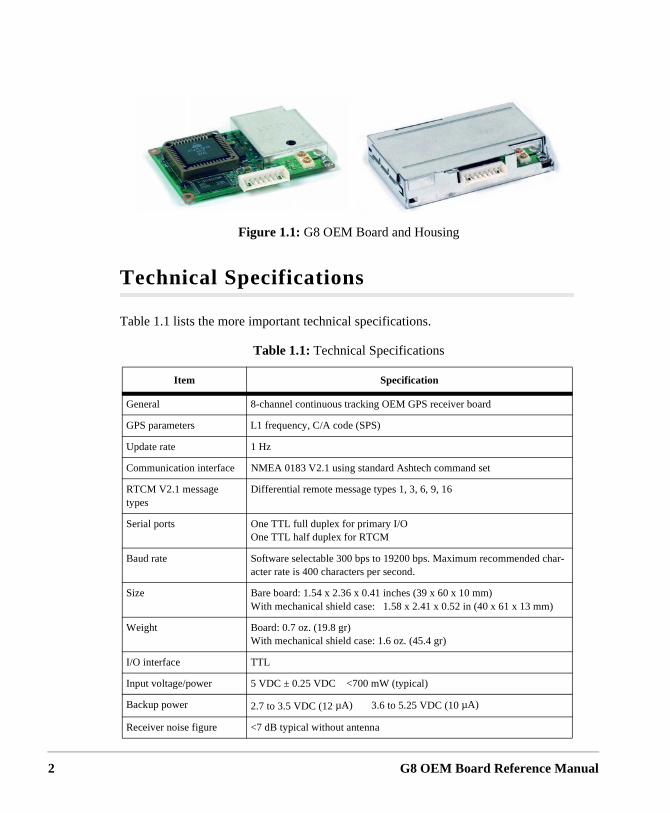
The G8 OEM board, Figure 1.1, fulfills the need for a low-cost, high-performance GPsensor, particularly where the requirements are for reliable positioning reporting in difficult environments such as vehicle navigation, fleet management, and personal amanagement (tracking of cars, boats, people, etc.). The G8 is designed for system integration, offering autonomous or DGPS positioning, low power, small size, and thstandard NMEA protocol. The G8 utilizes 5 VDC power and supports two TTL serialcommunication ports that are accessible through the I/O connector.
The G8 OEM board processes signals from the Global Positioning System (GPS) saconstellation to provide real-time position, velocity, and time measurements. The G8eight dedicated separate and parallel channels for Coarse/Acquisition (C/A) code-ph(a.k.a. pseudo-range) on the L1 (1575.42 MHz) band. The G8 receives satellite signaan L-band antenna with integral low-noise amplifier (an active antenna must be suppseparately). The G8 is designed for outputting position, speed, and time informationeither autonomously or differentially corrected using DGPS corrections in RTCM SC-Version 2.1 format.
formation 1
2
Technical Specifications
Table 1.1 lists the more important technical specifications.
Figure 1.1: G8 OEM Board and Housing
Table 1.1: Technical Specifications
Item Specification
General 8-channel continuous tracking OEM GPS receiver board
GPS parameters L1 frequency, C/A code (SPS)
Update rate 1 Hz
Communication interface NMEA 0183 V2.1 using standard Ashtech command set
RTCM V2.1 message types
Differential remote message types 1, 3, 6, 9, 16
Serial ports One TTL full duplex for primary I/OOne TTL half duplex for RTCM
Baud rate Software selectable 300 bps to 19200 bps. Maximum recommended char-acter rate is 400 characters per second.
Size Bare board: 1.54 x 2.36 x 0.41 inches (39 x 60 x 10 mm)With mechanical shield case: 1.58 x 2.41 x 0.52 in (40 x 61 x 13 mm)
Weight Board: 0.7 oz. (19.8 gr)With mechanical shield case: 1.6 oz. (45.4 gr)
I/O interface TTL
Input voltage/power 5 VDC ± 0.25 VDC <700 mW (typical)
Backup power 2.7 to 3.5 VDC (12 µA) 3.6 to 5.25 VDC (10 µA)
Receiver noise figure <7 dB typical without antenna
G8 OEM Board Reference Manual
General In
General Inform
ation
Performance Specifications
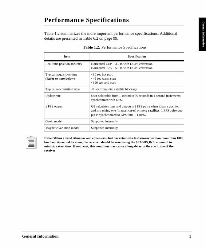
Table 1.2 summarizes the more important performance specifications. Additional details are presented in Table 6.2 on page 99.
If the G8 has a valid Almanac and ephemeris, but has retained a last known position more than 1000 km from its actual location, the receiver should be reset using the $PASHS,INI command to minimize start time. If not reset, this condition may cause a long delay in the start time of the receiver.
Table 1.2: Performance Specifications
Item Specification
Real-time position accuracy Horizontal CEP 3.0 m with DGPS correctionHorizontal 95% 5.0 m with DGPS correction
Typical acquisition time (Refer to note below)
<10 sec hot start<45 sec warm start<120 sec cold start
Typical reacquisition time <1 sec from total satellite blockage
Update rate User-selectable from 1 second to 99 seconds in 1-second increments synchronized with GPS.
1 PPS output G8 calculates time and outputs a 1 PPS pulse when it has a position and is tracking one (in most cases) or more satellites. 1 PPS pulse out-put is synchronized to GPS time ± 1 µsec.
Geoid model Supported internally
Magnetic variation model Supported internally
formation 3
4
Hardware Description
Physical Configuration
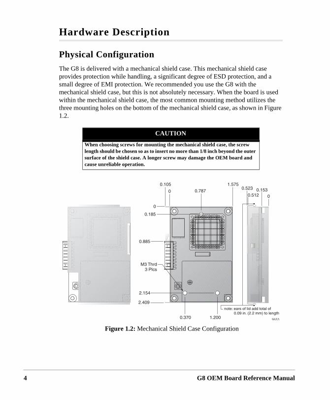
The G8 is delivered with a mechanical shield case. This mechanical shield case provides protection while handling, a significant degree of ESD protection, and a small degree of EMI protection. We recommended you use the G8 with the mechanical shield case, but this is not absolutely necessary. When the board is used within the mechanical shield case, the most common mounting method utilizes the three mounting holes on the bottom of the mechanical shield case, as shown in Figure 1.2.
CAUTION
When choosing screws for mounting the mechanical shield case, the screw length should be chosen so as to insert no more than 1/8 inch beyond the outer surface of the shield case. A longer screw may damage the OEM board and cause unreliable operation.
Figure 1.2: Mechanical Shield Case Configuration
G8 OEM Board Reference Manual
General In
General Inform
ation
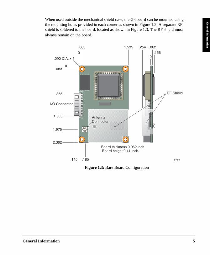
When used outside the mechanical shield case, the G8 board can be mounted using the mounting holes provided in each corner as shown in Figure 1.3. A separate RF shield is soldered to the board, located as shown in Figure 1.3. The RF shield must always remain on the board.
Figure 1.3: Bare Board Configuration
formation 5
6
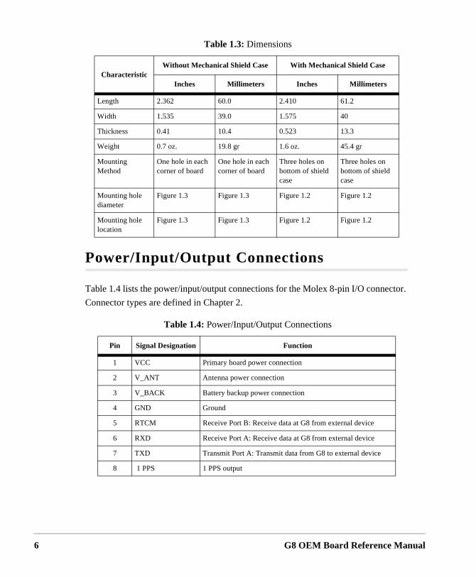
Power/Input/Output Connections
Table 1.4 lists the power/input/output connections for the Molex 8-pin I/O connector.
Connector types are defined in Chapter 2.
Table 1.3: Dimensions
CharacteristicWithout Mechanical Shield Case With Mechanical Shield Case
Inches Millimeters Inches Millimeters
Length 2.362 60.0 2.410 61.2
Width 1.535 39.0 1.575 40
Thickness 0.41 10.4 0.523 13.3
Weight 0.7 oz. 19.8 gr 1.6 oz. 45.4 gr
Mounting Method
One hole in each corner of board
One hole in each corner of board
Three holes on bottom of shield case
Three holes on bottom of shield case
Mounting hole diameter
Figure 1.3 Figure 1.3 Figure 1.2 Figure 1.2
Mounting hole location
Figure 1.3 Figure 1.3 Figure 1.2 Figure 1.2
Table 1.4: Power/Input/Output Connections
Pin Signal Designation Function
1 VCC Primary board power connection
2 V_ANT Antenna power connection
3 V_BACK Battery backup power connection
4 GND Ground
5 RTCM Receive Port B: Receive data at G8 from external device
6 RXD Receive Port A: Receive data at G8 from external device
7 TXD Transmit Port A: Transmit data from G8 to external device
8 1 PPS 1 PPS output
G8 OEM Board Reference Manual
General In
General Inform
ationat, s are
n-
y
l in
be
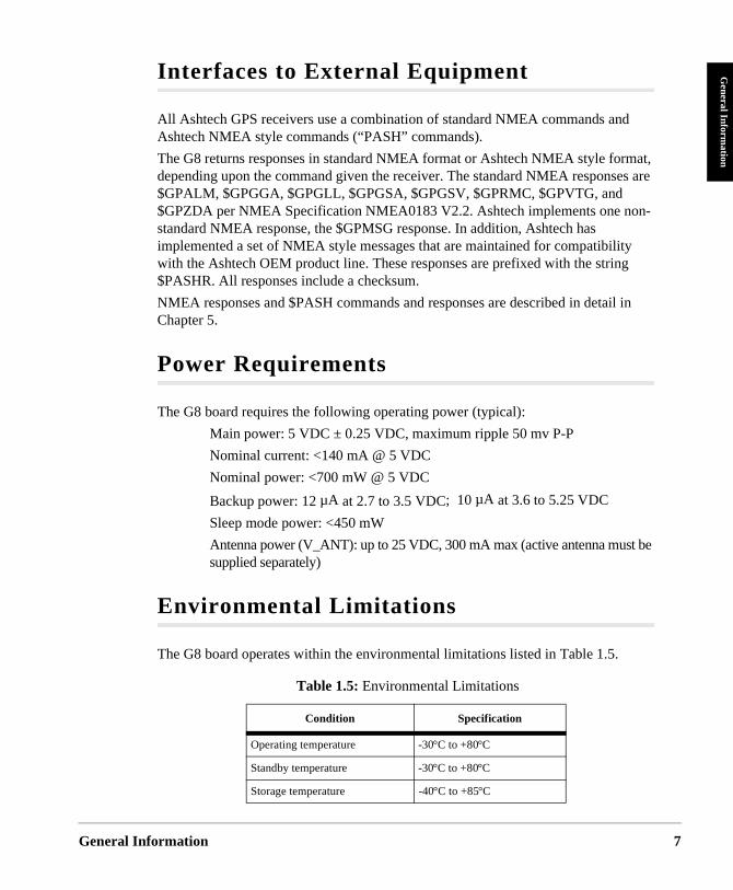
Interfaces to External Equipment
All Ashtech GPS receivers use a combination of standard NMEA commands and Ashtech NMEA style commands (“PASH” commands).
The G8 returns responses in standard NMEA format or Ashtech NMEA style formdepending upon the command given the receiver. The standard NMEA response$GPALM, $GPGGA, $GPGLL, $GPGSA, $GPGSV, $GPRMC, $GPVTG, and $GPZDA per NMEA Specification NMEA0183 V2.2. Ashtech implements one nostandard NMEA response, the $GPMSG response. In addition, Ashtech has implemented a set of NMEA style messages that are maintained for compatibilitwith the Ashtech OEM product line. These responses are prefixed with the string$PASHR. All responses include a checksum.
NMEA responses and $PASH commands and responses are described in detaiChapter 5.
Power Requirements
The G8 board requires the following operating power (typical):
Main power: 5 VDC ± 0.25 VDC, maximum ripple 50 mv P-P
Nominal current: <140 mA @ 5 VDC
Nominal power: <700 mW @ 5 VDC
Backup power: 12 µA at 2.7 to 3.5 VDC; 10 µA at 3.6 to 5.25 VDC
Sleep mode power: <450 mW
Antenna power (V_ANT): up to 25 VDC, 300 mA max (active antenna mustsupplied separately)
Environmental Limitations
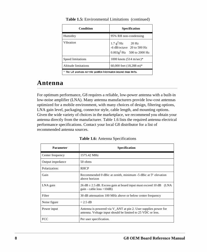
The G8 board operates within the environmental limitations listed in Table 1.5.
Table 1.5: Environmental Limitations
Condition Specification
Operating temperature -30°C to +80°C
Standby temperature -30°C to +80°C
Storage temperature -40°C to +85°C
formation 7
8
Antenna
For optimum performance, G8 requires a reliable, low-power antenna with a built-in low-noise amplifier (LNA). Many antenna manufacturers provide low-cost antennas optimized for a mobile environment, with many choices of design, filtering options, LNA gain level, packaging, connector style, cable length, and mounting options. Given the wide variety of choices in the marketplace, we recommend you obtain your antenna directly from the manufacturer. Table 1.6 lists the required antenna electrical performance specifications. Contact your local G8 distributor for a list of recommended antenna sources.
Humidity 95% RH non-condensing
Vibration 1.7 g2/Hz 20 Hz-6 dB/octave 20 to 500 Hz
0.003g2/Hz 500 to 2000 Hz
Speed limitations 1000 knots (514 m/sec)*
Altitude limitations 60,000 feet (18,288 m)*
��6JG�)��RTQFWEGU�PQ�XCNKF�RQUKVKQP�KPHQTOCVKQP�DG[QPF�VJGUG�NKOKVU�
Table 1.6: Antenna Specifications
Parameter Specification
Center frequency 1575.42 MHz
Output impedance 50 ohms
Polarization: RHCP
Gain Recommended 0 dBic at zenith, minimum -5 dBic at 5° elevation above horizon
LNA gain 26 dB ± 2.5 dB. Excess gain at board input must exceed 10 dB (LNA gain - cable loss >10dB)
Filter 30 dB attenuation 100 MHz above or below center frequency
Noise figure < 2.5 dB
Power input Antenna is powered via V_ANT at pin 2. User supplies power for antenna. Voltage input should be limited to 25 VDC or less.
FCC Per user specification.
Table 1.5: Environmental Limitations (continued)
Condition Specification
G8 OEM Board Reference Manual
General In
General Inform
ation
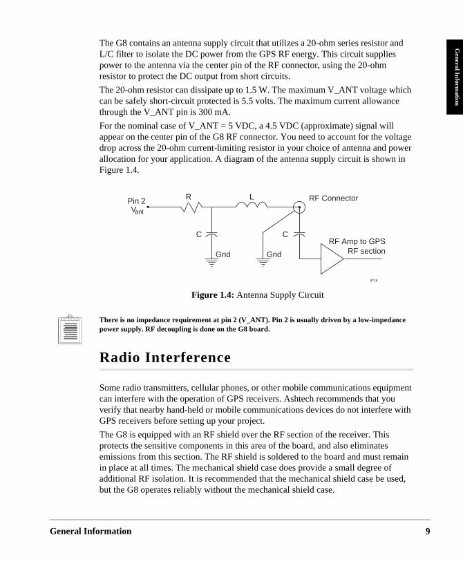
The G8 contains an antenna supply circuit that utilizes a 20-ohm series resistor and L/C filter to isolate the DC power from the GPS RF energy. This circuit supplies power to the antenna via the center pin of the RF connector, using the 20-ohm resistor to protect the DC output from short circuits.
The 20-ohm resistor can dissipate up to 1.5 W. The maximum V_ANT voltage which can be safely short-circuit protected is 5.5 volts. The maximum current allowance through the V_ANT pin is 300 mA.
For the nominal case of V_ANT = 5 VDC, a 4.5 VDC (approximate) signal will appear on the center pin of the G8 RF connector. You need to account for the voltage drop across the 20-ohm current-limiting resistor in your choice of antenna and power allocation for your application. A diagram of the antenna supply circuit is shown in Figure 1.4.
There is no impedance requirement at pin 2 (V_ANT). Pin 2 is usually driven by a low-impedance power supply. RF decoupling is done on the G8 board.
Radio Interference
Some radio transmitters, cellular phones, or other mobile communications equipment can interfere with the operation of GPS receivers. Ashtech recommends that you verify that nearby hand-held or mobile communications devices do not interfere with GPS receivers before setting up your project.
The G8 is equipped with an RF shield over the RF section of the receiver. This protects the sensitive components in this area of the board, and also eliminates emissions from this section. The RF shield is soldered to the board and must remain in place at all times. The mechanical shield case does provide a small degree of additional RF isolation. It is recommended that the mechanical shield case be used, but the G8 operates reliably without the mechanical shield case.
Figure 1.4: Antenna Supply Circuit
R L
C C
RF Connector
RF Amp to GPS RF sectionGnd
Pin 2Vant
9716
Gnd
formation 9

10
G8 OEM Board Reference Manual
2
Getting StartedGetting Sta
Getting Started
t or
tion.
General
This section outlines the following procedures to get your G8 GPS OEM board operating as quickly as possible:
• Procedure for connecting the G8 to power, the antenna, and your equipmensystem electronics
• Important communication parameters• Instructions for establishing communications with the G8 using typical
communications software with an IBM-compatible PC• Procedure for sending common commands to the G8
Quick Start
If you have the G8 Evaluation and Development Kit, use it for quick setup and evaluaGo directly to Chapter 4 for instructions. If you do not have the G8 Evaluation and Development Kit, proceed with the following instructions.
Connection Procedures
Board
Figure 2.1 shows the power and I/O connections to the 8-pin I/O connector on the board.
CAUTION
To avoid damage to the G8, always turn off the power supply before connect-ing or disconnecting to the 8-pin I/O connector.
rted 11
12
g
a
/N ave eller.
ble, the
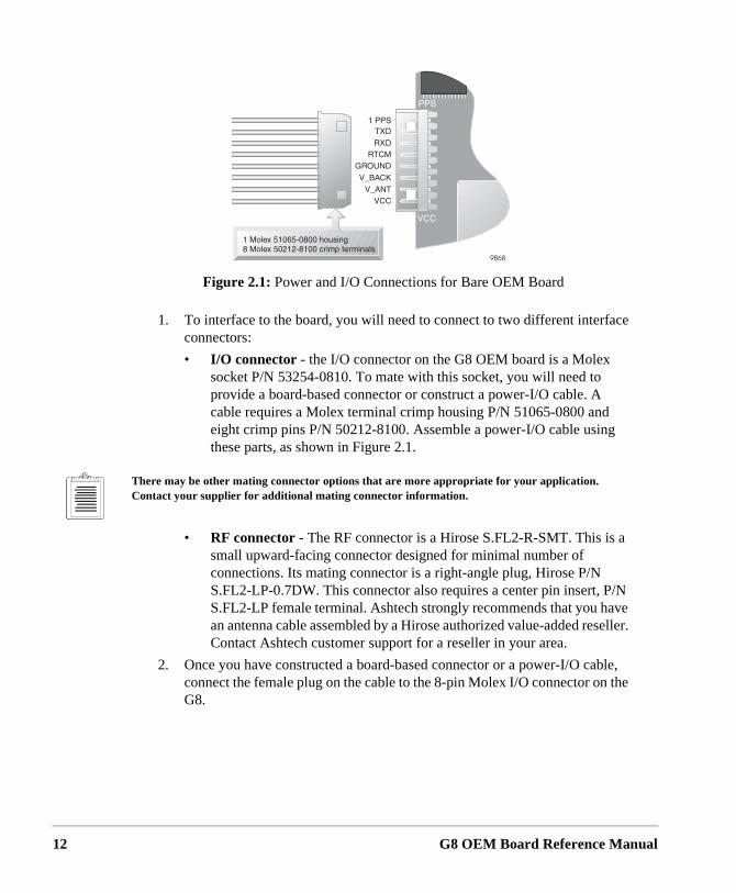
1. To interface to the board, you will need to connect to two different interface connectors:
• I/O connector - the I/O connector on the G8 OEM board is a Molex socket P/N 53254-0810. To mate with this socket, you will need to provide a board-based connector or construct a power-I/O cable. A cable requires a Molex terminal crimp housing P/N 51065-0800 andeight crimp pins P/N 50212-8100. Assemble a power-I/O cable usinthese parts, as shown in Figure 2.1.
There may be other mating connector options that are more appropriate for your application. Contact your supplier for additional mating connector information.
• RF connector - The RF connector is a Hirose S.FL2-R-SMT. This is small upward-facing connector designed for minimal number of connections. Its mating connector is a right-angle plug, Hirose P/N S.FL2-LP-0.7DW. This connector also requires a center pin insert, PS.FL2-LP female terminal. Ashtech strongly recommends that you han antenna cable assembled by a Hirose authorized value-added resContact Ashtech customer support for a reseller in your area.
2. Once you have constructed a board-based connector or a power-I/O caconnect the female plug on the cable to the 8-pin Molex I/O connector onG8.
Figure 2.1: Power and I/O Connections for Bare OEM Board
G8 OEM Board Reference Manual
Getting Sta
Getting Started
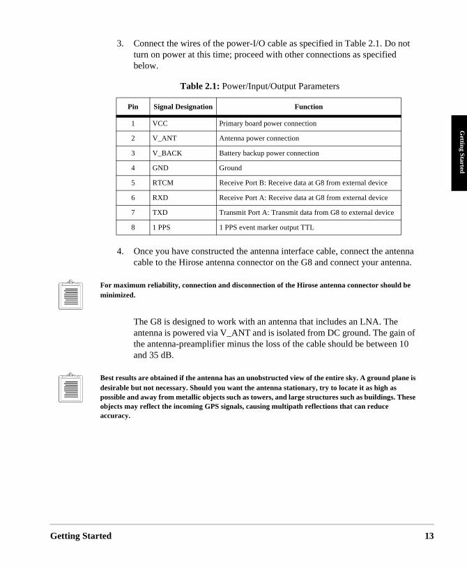
3. Connect the wires of the power-I/O cable as specified in Table 2.1. Do not turn on power at this time; proceed with other connections as specified below.
4. Once you have constructed the antenna interface cable, connect the antenna cable to the Hirose antenna connector on the G8 and connect your antenna.
For maximum reliability, connection and disconnection of the Hirose antenna connector should be minimized.
The G8 is designed to work with an antenna that includes an LNA. The antenna is powered via V_ANT and is isolated from DC ground. The gain of the antenna-preamplifier minus the loss of the cable should be between 10 and 35 dB.
Best results are obtained if the antenna has an unobstructed view of the entire sky. A ground plane is desirable but not necessary. Should you want the antenna stationary, try to locate it as high as possible and away from metallic objects such as towers, and large structures such as buildings. These objects may reflect the incoming GPS signals, causing multipath reflections that can reduce accuracy.
Table 2.1: Power/Input/Output Parameters
Pin Signal Designation Function
1 VCC Primary board power connection
2 V_ANT Antenna power connection
3 V_BACK Battery backup power connection
4 GND Ground
5 RTCM Receive Port B: Receive data at G8 from external device
6 RXD Receive Port A: Receive data at G8 from external device
7 TXD Transmit Port A: Transmit data from G8 to external device
8 1 PPS 1 PPS event marker output TTL
rted 13
14
data. gent TTL ).
t
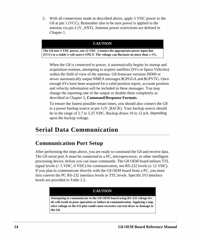
5. With all connections made as described above, apply 5 VDC power to the G8 at pin 1 (VCC). Remember also to be sure power is applied to the antenna via pin 2 (V_ANT). Antenna power restrictions are defined in Chapter 1.
When the G8 is connected to power, it automatically begins its startup and acquisition routines, attempting to acquire satellites (SVs or Space Vehicles) within the field of view of the antenna. G8 firmware versions HD00 or newer automatically output NMEA messages $GPGGA and $GPVTG. Once enough SVs have been acquired for a valid position report, accurate position and velocity information will be included in these messages. You may change the reporting rate of the output or disable them completely as described in Chapter 5, Command/Response Formats.
To ensure the fastest possible restart times, you should also connect the G8 to a power backup source at pin 3 (V_BACK). Your backup source should be in the range of 2.7 to 5.25 VDC. Backup draws 10 to 12 µA, depending upon the backup voltage.
Serial Data Communication
Communication Port Setup
After performing the steps above, you are ready to command the G8 and receiveThe G8 serial port A must be connected to a PC, microprocessor, or other intelliprocessing device, before you can issue commands. The G8 OEM board utilizessignal levels (+ 5 VDC, 0 VDC) for communication, not RS-232 levels (± 12 VDCIf you plan to communicate directly with the G8 OEM board from a PC, you musfirst convert the PC RS-232 interface levels to TTL levels. Specific I/O interface levels are provided in Table 2.2.
CAUTION
The G8 uses 5 VDC power, not 12 VDC. Connect the appropriate power input line (VCC) to a stable 5-volt source ONLY. The voltage can fluctuate no more than ± 5%.
CAUTION
Attempting to communicate to the G8 OEM board using RS-232 voltage lev-els will result in poor operation or failure in communication. Applying a neg-ative voltage to the I/O pins could cause excessive current draw or damage to the G8.
G8 OEM Board Reference Manual
Getting Sta
Getting Started
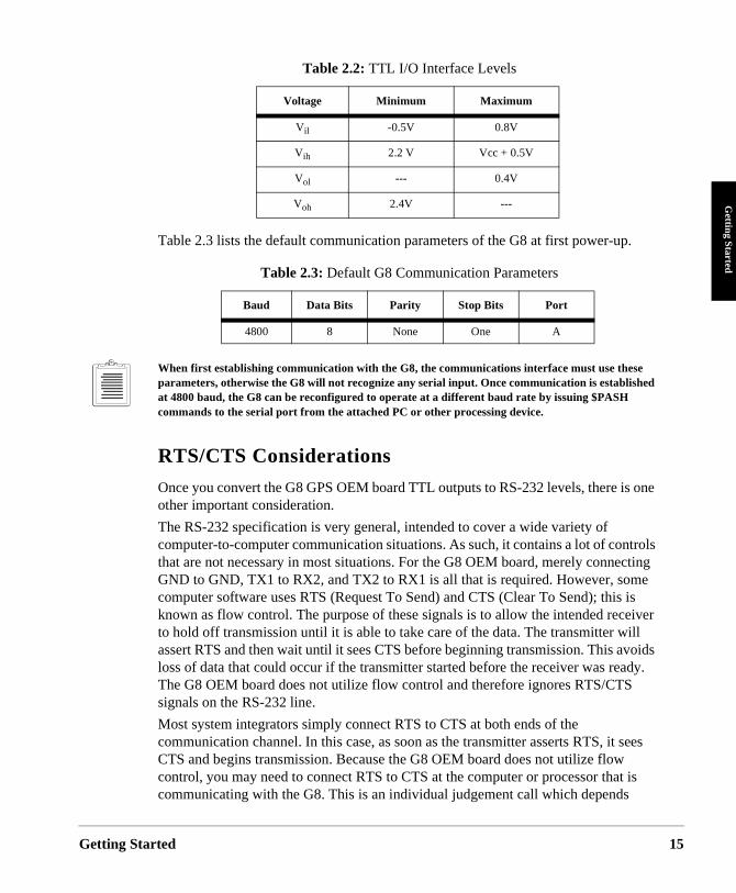
Table 2.3 lists the default communication parameters of the G8 at first power-up.
When first establishing communication with the G8, the communications interface must use these parameters, otherwise the G8 will not recognize any serial input. Once communication is established at 4800 baud, the G8 can be reconfigured to operate at a different baud rate by issuing $PASH commands to the serial port from the attached PC or other processing device.
RTS/CTS Considerations
Once you convert the G8 GPS OEM board TTL outputs to RS-232 levels, there is one other important consideration.
The RS-232 specification is very general, intended to cover a wide variety of computer-to-computer communication situations. As such, it contains a lot of controls that are not necessary in most situations. For the G8 OEM board, merely connecting GND to GND, TX1 to RX2, and TX2 to RX1 is all that is required. However, some computer software uses RTS (Request To Send) and CTS (Clear To Send); this is known as flow control. The purpose of these signals is to allow the intended receiver to hold off transmission until it is able to take care of the data. The transmitter will assert RTS and then wait until it sees CTS before beginning transmission. This avoids loss of data that could occur if the transmitter started before the receiver was ready. The G8 OEM board does not utilize flow control and therefore ignores RTS/CTS signals on the RS-232 line.
Most system integrators simply connect RTS to CTS at both ends of the communication channel. In this case, as soon as the transmitter asserts RTS, it sees CTS and begins transmission. Because the G8 OEM board does not utilize flow control, you may need to connect RTS to CTS at the computer or processor that is communicating with the G8. This is an individual judgement call which depends
Table 2.2: TTL I/O Interface Levels
Voltage Minimum Maximum
Vil -0.5V 0.8V
Vih 2.2 V Vcc + 0.5V
Vol --- 0.4V
Voh 2.4V ---
Table 2.3: Default G8 Communication Parameters
Baud Data Bits Parity Stop Bits Port
4800 8 None One A
rted 15
16
upon both the hardware configuration of the host and on the design of the software in the host. It may or may not be necessary, but should be considered in your interface design. The G8 Evaluator (see Chapter 4) connects the RTS and CTS lines; the G8 OEM board does not.
Default Data Output
For G8 firmware version HC00 and earlier versions all the default data output commands are set to NO (i.e., no output). Even though the G8 may be calculating positions, it does not output any data until you send a message commanding it to do so. For firmware versions HD00 and later, the G8 will automatically output the $GPGGA and &GPVTG message on startup.
Data Rate Limitations
The maximum recommended data I/O rate for the G8 is 400 characters per second. This equates to approximately six standard NMEA responses. Choose data output carefully so as not to overrun this maximum. If the maximum rate is exceeded the G8 may perform unreliably.
Initial Operating Instructions
After the G8 is powered and running, you may send it command messages in order to change the output or modify operating parameters. The following procedure describes briefly how to send commands to and receive information from the G8 using an IBM-compatible PC. Many standard communications software packages allow you to interface with the G8. Be sure to send commands to Port A of the G8 receiver.
Your command can be typed in upper or lower case, and must be completed by pressing the <enter> key. If you have typed and sent the command correctly, you should get an ACK response for a correct command, and a NAK response for an illegal or incorrect command. To become familiar with the G8 messages, send a few common commands to the G8 and observe the responses.
1. Type: $PASHQ,PRT and press <enter>. This command queries the communication setup of the port.
Pressing <enter> is equivalent to <CR><LF>.
2. The response message is:
$PASHR,PRT,A,4
This message indicates port A of the G8 is using its default communications setup 4, which is 4800 baud, eight data bits, no parity, and one stop bit. For
G8 OEM Board Reference Manual
Getting Sta
Getting Started
details of this command, refer to $PASHS,SPD and $PASHQ,PRT in Chapter 5.
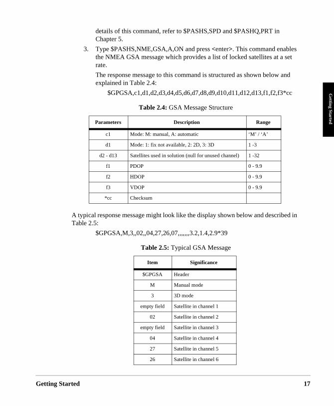
3. Type $PASHS,NME,GSA,A,ON and press <enter>. This command enables the NMEA GSA message which provides a list of locked satellites at a set rate.
The response message to this command is structured as shown below and explained in Table 2.4:
$GPGSA,c1,d1,d2,d3,d4,d5,d6,d7,d8,d9,d10,d11,d12,d13,f1,f2,f3*cc
A typical response message might look like the display shown below and described in Table 2.5:
$GPGSA,M,3,,02,,04,27,26,07,,,,,,,3.2,1.4,2.9*39
Table 2.4: GSA Message Structure
Parameters Description Range
c1 Mode: M: manual, A: automatic ‘M’ / ‘A’
d1 Mode: 1: fix not available, 2: 2D, 3: 3D 1 -3
d2 - d13 Satellites used in solution (null for unused channel) 1 -32
f1 PDOP 0 - 9.9
f2 HDOP 0 - 9.9
f3 VDOP 0 - 9.9
*cc Checksum
Table 2.5: Typical GSA Message
Item Significance
$GPGSA Header
M Manual mode
3 3D mode
empty field Satellite in channel 1
02 Satellite in channel 2
empty field Satellite in channel 3
04 Satellite in channel 4
27 Satellite in channel 5
26 Satellite in channel 6
rted 17
18
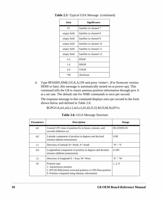
4. Type $PASHS,NME,GGA,A,ON and press <enter>. (For firmware version HD00 or later, this message is automatically turned on at power-up). This command tells the G8 to return antenna position information through port A at a set rate. The default rate for NME commands is once per second.
The response message to this command displays once per second in the form shown below and defined in Table 2.6:
$GPGGA,m1,m2,c1,m3,c2,d1,d2,f1,f2,M,f3,M,f4,d3*cc
07 Satellite in channel 7
empty field Satellite in channel 8
empty field Satellite in channel 9
empty field Satellite in channel 10
empty field Satellite in channel 11
empty field Satellite in channel 12
3.2 PDOP
1.4 HDOP
2.9 VDOP
*38 checksum
Table 2.6: GGA Message Structure
Parameters Description Range
m1 Current UTC time of position fix in hours, minutes, and seconds (ddmmss.ss)
00-235959.50
m2 Latitude component of position in degrees and decimal minutes (ddmm.mmmmmm)
0-90
c1 Direction of latitude N= North, S= South ‘N’ / ‘S’
m3 Longitudinal component of position in degrees and decimal minutes (dddmm.mmmmmm)
0-180
c2 Direction of longitude E = East, W= West ‘E’ / ‘W’
d1 Position type1. Autonomous position2. RTCM differential corrected position or CPD float position9. Position computed using almanac information
1, 2, 9
Table 2.5: Typical GSA Message (continued)
Item Significance
G8 OEM Board Reference Manual
Getting Sta
Getting Started
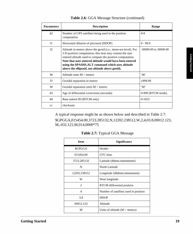
A typical response might be as shown below and described in Table 2.7:
$GPGGA,015454.00,3723.285132,N,12202.238512,W,2,4,03.8,00012.123,M,-032.121,M,014,0000*75
d2 Number of GPS satellites being used in the position computation
0-8
f1 Horizontal dilution of precision (HDOP) 0 - 99.9
f2 Altitude in meters above the geoid (i.e., mean-sea level). For 2-D position computation, this item may contain the user entered altitude used to compute the position computation. Note that user-entered altitude would have been entered using the $PASHS,ALT command which uses altitude above the ellipsoid, not altitude above geoid).
-30000.00 to 30000.00
M Altitude units M = meters ‘M’
f3 Geoidal separation in meters ±999.99
M Geoidal separation units M = meters ‘M’
d3 Age of differential corrections (seconds) 0-999 (RTCM mode)
d4 Base station ID (RTCM only) 0-1023
cc checksum
Table 2.7: Typical GGA Message
Item Significance
$GPGGA Header
015454.00 UTC time
3723.285132 Latitude (ddmm.mmmmmm)
N North Latitude
12202.238512 Longitude (dddmm.mmmmmm)
W West longitude
2 RTCM differential position
4 Number of satellites used in position
3.8 HDOP
00012.123 Altitude
M Units of altitude (M = meters)
Table 2.6: GGA Message Structure (continued)
Parameters Description Range
rted 19
20
h,
e G8
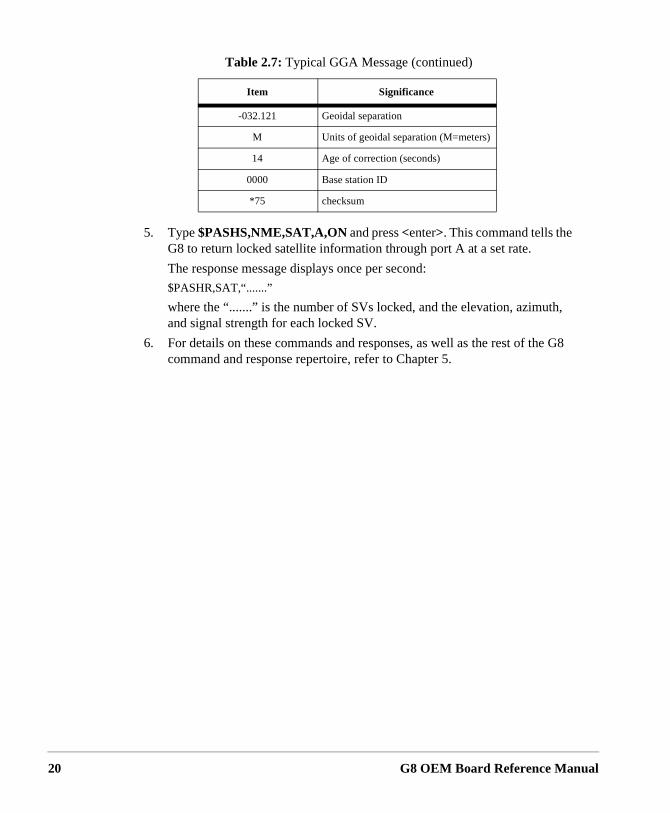
5. Type $PASHS,NME,SAT,A,ON and press <enter>. This command tells the G8 to return locked satellite information through port A at a set rate.
The response message displays once per second:
$PASHR,SAT,“.......”
where the “.......” is the number of SVs locked, and the elevation, azimutand signal strength for each locked SV.
6. For details on these commands and responses, as well as the rest of thcommand and response repertoire, refer to Chapter 5.
-032.121 Geoidal separation
M Units of geoidal separation (M=meters)
14 Age of correction (seconds)
0000 Base station ID
*75 checksum
Table 2.7: Typical GGA Message (continued)
Item Significance
G8 OEM Board Reference Manual
3
OperationOperation
Operation
y the R-
*.
l)
This section summarizes system setup, G8 operation at power-up, input and output messages, serial port configuration, parameter settings and status, the satellite search algorithm, modes of operation, antenna position setting, NMEA outputs, and differential operation.
System Setup
Verify that the G8 is set up as described in Chapter 2.
Message Format
The G8 command/response firmware allocates the two RS-232 ports (A and B) to receive command messages from an external control device (such as a PC), and receive differential corrections from a reference station. Commands can be input to either port A or B, but only port A provides responses to commands.
Input Messages to the G8
The input messages comprise set command messages, and query command messages. The set commands instruct the G8 to perform a specified and often continuous activity; the query commands instruct the G8 to report its present status one time only. The general command messages comply with the NMEA 0183 standard to the following extent:
• NMEA 0183 ASCII strings following $ character• Headers are Ashtech NMEA style, registered with NMEA (i.e., PASH)• Message IDs are Ashtech NMEA style• Data items are separated by commas• Checksum character delimiter and NMEA checksum bytes are recognized b
G8 but are optional. The hexadecimal checksum is computed by exclusive Oing all of the bytes in the message between, but not including, the $ and the
• Message is ended with the standard NMEA message terminator characters,<CR> and <LF> (same as <enter>).ll command messages (set, query or generarecognize upper or lower case letters. They are accepted by <enter>. A valid set command causes the G8 to return the $PASHR,ACK*3D, “acknowledged” response message. A set command containing a valid $PASHS set command header followed by character combinations unrecognized by the G8 causes return of the $PASHR,NAK*30, “not-acknowledged” response message. All other invalid set commands are ignored. Valid query and general command messages
21
22
slid or
ator
le
e for
d rate
ort for a
are acknowledged by return of the requested information, and all invalid query and general commands cause the G8 to return the $PASHR,NAK*30 “ not acknowledged” response message.
Output Messages From the G8
Output messages are messages the G8 sends to the PC or system electronics in response to a command message. These messages comprise G8 general status messages, command acknowledged/not acknowledged messages, and GPS data messages. The G8 general status messages have free-form Ashtech NMEA style formats. The command acknowledged/not acknowledged messages and GPS data messages comply with NMEA 0183 as follows:
• NMEA ASCII strings following $-character• Headers are standard NMEA or Ashtech NMEA style• Message IDs are standard NMEA or Ashtech NMEA style• Standard NMEA format messages contain hexadecimal checksum byte• Data items are separated by commas; successive commas indicate inva
missing data (null fields)• Message is ended with <CR><LF>, the standard NMEA message termin
characters
Serial Port Configuration
Port A provides two-way full duplex RS-232 communication. Be aware that the signals are, however, at TTL levels. The default transmit/receive protocol is 4800baud, eight data bits, no parity, and one stop bit (8N1). The baud rate is adjustabusing the $PASHS,SPD speed set command; the data bit, stop bit and parity protocol are always 8N1.
On initial power-up or after issuing the $PASHS,RST (reset to defaults) command,the G8 default is 4800 baud for both RS-232 serial ports A and B.
The baud rates between the G8 and the interfacing equipment must be the samboth the port and the device connected to that port.
To maintain communication with the G8 while changing the baud rate, issue the$PASHS,SPD (set command) to change the G8 baud rate, then change the bauof the command device to match the new G8 rate.
Antenna Connection
The G8 requires that a compatible active antenna be connected to the antenna preliable operation. Antenna specifications are provided in Chapter 1. The antenn
G8 OEM Board Reference Manual
Operation
Operation
must have a clear view of the entire sky in order for the G8 to meet the specifications defined in this manual.
Satellite Search Algorithm
When the G8 is operated for the first time after receipt from Ashtech, or after the power and back-up battery have been disconnected, no almanac or ephemeris data are available. The G8 always assigns the first eight elements of a 32-element table of SV PRN numbers to its eight channels. Within 35 to 40 seconds after locking the first SV, the G8 time is set. The G8 computes its first position after three (for 2D) or four (for 3D) SVs are locked, provided that the satellite geometry is adequate. The G8 continuously stores the most recent almanac, ephemeris, and position data into its battery-backed memory, which allows for faster position computation when next turned on.
The G8 performs a cold start if there are no valid almanac or ephemeris data in the battery-backed memory, or if it has no previously known position; this is generally true if the G8 has been off for more than six months. With no SV information to help narrow the search, cold start typically requires about two minutes to compute the initial position. If the G8 has been off for less than six months but more than four to six hours, then the stored almanac and position data allow it to narrow the SV search and perform a warm start. In warm start the initial position is typically computed in about 30 seconds. The G8 will turn on with a hot start if its battery-backed memory contains valid almanac, ephemeris, and position data; this is generally true if the G8 has been off for no more than four to six hours. This data allows the G8 to search only for visible SVs in known locations, and the first position is typically computed in about 10 seconds.
If the G8 has a valid Almanac and ephemeris, but has retained a last known position more than 1000 km from its actual location, the receiver should be reset using the $PASHS,INI command to minimize start time. If not reset, this condition may cause a long delay in the start time of the receiver.
Parameter Settings and Status
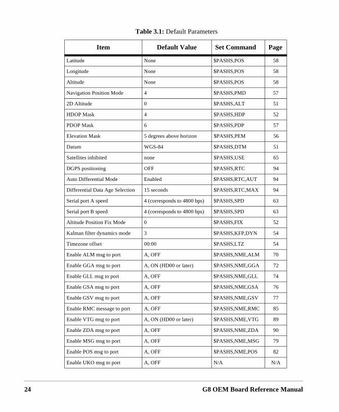
The G8 has the default operational parameters listed in Table 3.1. These parameters can be changed using the indicated set commands; detailed explanations of the set commands are presented in chapter 5.
23
24
Table 3.1: Default Parameters
Item Default Value Set Command Page
Latitude None $PASHS,POS 58
Longitude None $PASHS,POS 58
Altitude None $PASHS,POS 58
Navigation Position Mode 4 $PASHS,PMD 57
2D Altitude 0 $PASHS,ALT 51
HDOP Mask 4 $PASHS,HDP 52
PDOP Mask 6 $PASHS,PDP 57
Elevation Mask 5 degrees above horizon $PASHS,PEM 56
Datum WGS-84 $PASHS,DTM 51
Satellites inhibited none $PASHS,USE 65
DGPS positioning OFF $PASHS,RTC 94
Auto Differential Mode Enabled $PASHS,RTC,AUT 94
Differential Data Age Selection 15 seconds $PASHS,RTC,MAX 94
Serial port A speed 4 (corresponds to 4800 bps) $PASHS,SPD 63
Serial port B speed 4 (corresponds to 4800 bps) $PASHS,SPD 63
Altitude Position Fix Mode 0 $PASHS,FIX 52
Kalman filter dynamics mode 3 $PASHS,KFP,DYN 54
Timezone offset 00:00 $PASHS,LTZ 54
Enable ALM msg to port A, OFF $PASHS,NME,ALM 70
Enable GGA msg to port A, ON (HD00 or later) $PASHS,NME,GGA 72
Enable GLL msg to port A, OFF $PASHS,NME,GLL 74
Enable GSA msg to port A, OFF $PASHS,NME,GSA 76
Enable GSV msg to port A, OFF $PASHS,NME,GSV 77
Enable RMC message to port A, OFF $PASHS,NME,RMC 85
Enable VTG msg to port A, ON (HD00 or later) $PASHS,NME,VTG 89
Enable ZDA msg to port A, OFF $PASHS,NME,ZDA 90
Enable MSG msg to port A, OFF $PASHS,NME,MSG 79
Enable POS msg to port A, OFF $PASHS,NME,POS 82
Enable UKO msg to port A, OFF N/A N/A
G8 OEM Board Reference Manual
Operation
Operation
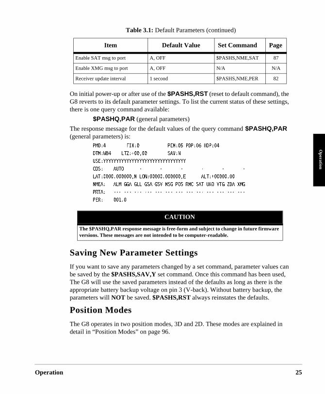
On initial power-up or after use of the $PASHS,RST (reset to default command), the G8 reverts to its default parameter settings. To list the current status of these settings, there is one query command available:
$PASHQ,PAR (general parameters)
The response message for the default values of the query command $PASHQ,PAR (general parameters) is:
2/&����������(+:�������������2'/����2&2����*&2������
&6/�9������.6<� �������������5#8�0�
75'�;;;;;;;;;;;;;;;;;;;;;;;;;;;;;;;;�
%&5�����#761������������������������������������������������
.#6�������������0�.10��������������'������#.6� ��������
0/'#����#./�))#�)..�)5#�)58�/5)�215�4/%�5#6�7-1�86)�<&#�:/)�
246#�������������������������������������������������������
2'4������������
Saving New Parameter Settings
If you want to save any parameters changed by a set command, parameter values can be saved by the $PASHS,SAV,Y set command. Once this command has been used, The G8 will use the saved parameters instead of the defaults as long as there is the appropriate battery backup voltage on pin 3 (V-back). Without battery backup, the parameters will NOT be saved. $PASHS,RST always reinstates the defaults.
Position Modes
The G8 operates in two position modes, 3D and 2D. These modes are explained in detail in “Position Modes” on page 96.
Enable SAT msg to port A, OFF $PASHS,NME,SAT 87
Enable XMG msg to port A, OFF N/A N/A
Receiver update interval 1 second $PASHS,NME,PER 82
CAUTION
The $PASHQ,PAR response message is free-form and subject to change in future firmware versions. These messages are not intended to be computer-readable.
Table 3.1: Default Parameters (continued)
Item Default Value Set Command Page
25
26
d by
ough
Altitude Hold Definition
Two modes are available to determine what altitude is selected when the G8 is in altitude-hold mode. The $PASHS,FIX set command can be used to select between these modes.
• In mode 0, the most recent altitude is used. This is either the one entereusing the $PASHS,ALT or $PASHS,POS set command or the one computed as part of a 3D position, whichever is most recent.
• In mode 1, only the last altitude entered by using the $PASHS,ALT set command is used in the position fix solution.
On initial power-up or after use of the $PASHS,RST default parameter reset command, the most recent antenna altitude is zero.
Antenna Position Setting
Two commands are available to enter the known antenna position:
$PASHS,POS (position setting including latitude, longitude, altitude)
$PASHS,ALT (altitude for fixed 2D operation)
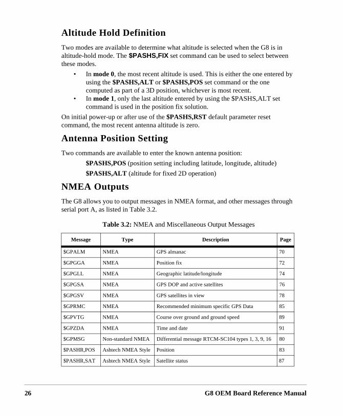
NMEA Outputs
The G8 allows you to output messages in NMEA format, and other messages thrserial port A, as listed in Table 3.2.
Table 3.2: NMEA and Miscellaneous Output Messages
Message Type Description Page
$GPALM NMEA GPS almanac 70
$GPGGA NMEA Position fix 72
$GPGLL NMEA Geographic latitude/longitude 74
$GPGSA NMEA GPS DOP and active satellites 76
$GPGSV NMEA GPS satellites in view 78
$GPRMC NMEA Recommended minimum specific GPS Data 85
$GPVTG NMEA Course over ground and ground speed 89
$GPZDA NMEA Time and date 91
$GPMSG Non-standard NMEA Differential message RTCM-SC104 types 1, 3, 9, 16 80
$PASHR,POS Ashtech NMEA Style Position 83
$PASHR,SAT Ashtech NMEA Style Satellite status 87
G8 OEM Board Reference Manual
Operation
Operation
mote tation G8
base onse, d to ch
sent
nge iver. other
ly s. In
Any combination of these messages can be output through serial port A. The output rate is determined by the $PASHS,NME,PER command, and can be set to any value between 1 and 999 seconds. Additional details are presented in the discussion of NMEA message commands in Chapter 5, Command/Response Formats.
G8 message outputs should be chosen so as not to overrun the maximum recommended character rate of 400 characters per second. This equates to approximately six standard NMEA responses. Overrunning this output rate may cause unreliable G8 operation.
All standard NMEA messages are a string of ASCII characters delimited by commas and that comply with the NMEA 0183 standard, Version 2.1. All non-standard messages are a string of ASCII characters delimited by commas using the Ashtech NMEA style response format.
Differential Operation
This section discusses differential operation in general, sources of error, the G8 messages for differential operation, and RTCM 104 format as it applies to a remote station.
General
Real-time “Broadcast” differential GPS positioning (DGPS) involves a reference (base) station computing the SV range corrections and transmitting them to a re(rover) unit. The G8 is designed to operate as a remote unit. When a reference stransmits these corrections in real time to the G8 via a communications link, theapplies the corrections to its measured ranges and uses the corrected ranges tocompute its position.
Real time “inverse” differential positioning uses DGPS corrections applied at the instead of at the remote unit. The G8 can be set to output the $PASHR,ITA respwhich outputs pseudorange and doppler information for each SV that can be useapply corrections back at the base station. As with broadcast DGPS, this approarequires an efficient communication link since the $PASHR, ITA output must be to the base for processing.
The base receiver determines range corrections by subtracting the measured rafrom the true range, computed by using an accurate position entered in the receThis accurate position must have been previously surveyed using GPS or sometechnique.
As a stand-alone receiver, and with SA (Selective Availability) on, the G8 typicalcomputes a position within about 30 meters of truth but always within 100 meterdifferential mode, the G8 can achieve better than 3m (CEP) precision. For both
27
28
broadcast and inverse DGPS operation, a communication link must exist between the base and remote receivers. The communication link can be a radio link, telephone line, cellular phone, communications satellite link, or any other medium that can transfer digital data.
Sources of Error
The major sources of error affecting the accuracy of GPS range measurements are SA (Selective Availability), SV orbit estimation, SV clock estimation, ionosphere, troposphere, and receiver noise in measuring range. The first five sources of error are almost totally removed using differential GPS.
Receiver noise is not correlated between the base and the remote receiver and is not cancelled by differential GPS.
Total position error (or error-in-position) is a function of the range errors (or errors-in-range) multiplied by the PDOP (three-coordinate position dilution of precision). The PDOP is a function of the geometry of the SVs.
RTCM Messages
For broadcast DGPS mode the G8 accepts RTCM SC-104 Version 2.2 differential formats. The G8 is set to receive RTCM corrections in either of the two ports by issuing the set command $PASHS,RTC,REM,c where c is the port. Of RTCM message types 1 through 64, the G8 processes types 3 and 16 for station location and special information; types 1 and 9 for RTCM differential corrections; and null frame type 6. The differential corrections are automatically processed by the G8.
It is recommended, but not required, that RTCM information be input on port B.
RTCM message types 3 and 16 provide user information from the reference (base) station, while RTCM message types 1 and 9 provide differential correction information. The reference station sends types 1 and 9 continuously and may send either type 3 or type 16 individually. The $PASHS,NME,MSG set command and $PASHQ,MSG query command cause the most recent RTCM input data to be reported, via the $GPMSG message.
On initial power-up or after use of the $PASHS,RST (reset to defaults command) the G8 default automatic differential mode is OFF, and the default is 15 seconds for the maximum age of an RTCM differential correction, above which it is not be used. If the automatic mode is not enabled by the $PASHS,RTC,AUT set command and the differential correction data is older than the maximum age specified by the $PASHS,RTC,MAX set command, the G8 does not return antenna position data.
In automatic mode, if no differential correction data is received or the age of data is older than the specified maximum age, the G8 returns the uncorrected position.
G8 OEM Board Reference Manual
Operation
Operation
e 1
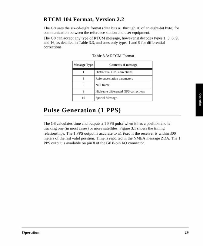
RTCM 104 Format, Version 2.2
The G8 uses the six-of-eight format (data bits a1 through a6 of an eight-bit byte) for communication between the reference station and user equipment.
The G8 can accept any type of RTCM message, however it decodes types 1, 3, 6, 9, and 16, as detailed in Table 3.3, and uses only types 1 and 9 for differential corrections.
Pulse Generation (1 PPS)
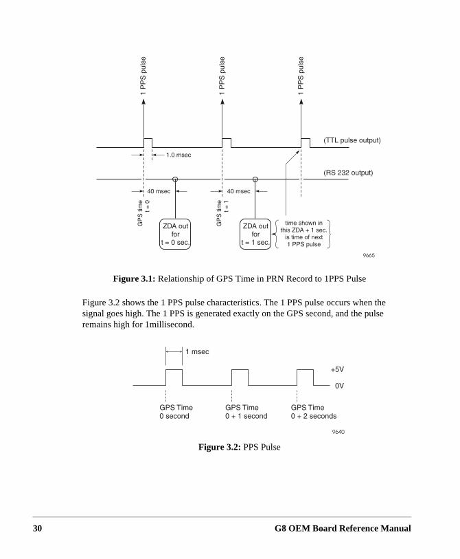
The G8 calculates time and outputs a 1 PPS pulse when it has a position and is tracking one (in most cases) or more satellites. Figure 3.1 shows the timing relationships. The 1 PPS output is accurate to ±1 µsec if the receiver is within 300 meters of the last valid position. Time is reported in the NMEA message ZDA. ThPPS output is available on pin 8 of the G8 8-pin I/O connector.
Table 3.3: RTCM Format
Message Type Contents of message
1 Differential GPS corrections
3 Reference station parameters
6 Null frame
9 High-rate differential GPS corrections
16 Special Message
29
30
Figure 3.2 shows the 1 PPS pulse characteristics. The 1 PPS pulse occurs when the signal goes high. The 1 PPS is generated exactly on the GPS second, and the pulse remains high for 1millisecond.
Figure 3.1: Relationship of GPS Time in PRN Record to 1PPS Pulse
Figure 3.2: PPS Pulse
G8 OEM Board Reference Manual
4
Evaluation and Development KitEvaluation K
it
Evaluation
nts
ps
Overview
The G8 Evaluation and Development Kit, Figure 4.1, lets you rapidly set up and operate the G8 to determine suitability for your application. The G8 Evaluation and Development Kit can also be used for software development (experimenting with commands, etc.) and for troubleshooting once your system is deployed.
The G8 Evaluation and Development Kit provides the following conveniences which would otherwise have to be devised by the user:
• Built-in RS-232 interface does TTL to RS-232 conversion for you
• Standard SMA connector for antenna connection
• Standard serial interface connector connects directly to PC
• Standard BNC connector on back panel for 1 PPS output
• Packaged unit protects OEM board in rugged test and evaluation environme
• Connects to standard 12 VDC power (such as a vehicle battery)
• Built-in battery eliminates need for battery backup connection
• Wide range of input power provides flexibility in test setups
• All interface cabling is provided for you
Configuring Your Kit for Operation
To configure and operate your G8 Evaluation and Development kit, follow the six stebelow in sequence. For detailed mounting instructions and detailed cable connectioninformation, refer to the appropriate sections later in this chapter.
and Development Kit 31
32
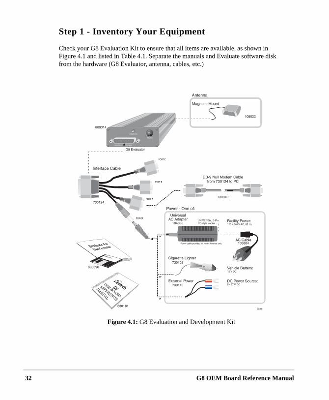
Step 1 - Inventory Your Equipment
Check your G8 Evaluation Kit to ensure that all items are available, as shown in Figure 4.1 and listed in Table 4.1. Separate the manuals and Evaluate software disk from the hardware (G8 Evaluator, antenna, cables, etc.)
Figure 4.1: G8 Evaluation and Development Kit
G8 OEM Board Reference Manual
Evaluation
Evaluation K
it
on is ed, is in
s 1
the
Step 2 - Load the Evaluate software into your computer
Refer to the Evaluate User’s Guide P/N 630063. Follow the setup and software loading instructions in the guide.
When you load the Evaluate software into the PC, make sure the software versi4.01 or later, earlier versions will not work with the G8. After your software is loadthere is no need to launch the Evaluate application. You will be instructed to do tha later step.
Step 3 - Prepare Your Equipment for Operation
Connect devices as shown in Figure 4.2. It is very important to follow instructionthrough 6 below.
1. Connect the multiport interface cable 730124 to the DB-25 connector onG8 Evaluator.
2. Connect the DB-9 null modem cable from the port A connector (labelled“Port A-1 PPS Out”) on the interface cable to an initialized serial port onyour IBM-compatible computer. If the serial port of your computer is notinitialized, it will not be recognized by the Evaluate software.
Within the G8 Evaluator, the RTS/CTS lines of the interface cable are connected. This is done to ensure that your computer will always receive an immediate CTS signal when it asserts RTS as part of its communication process. Refer to Table 4.7 on page 41 for specific interconnection details.
Port B of interface cable (730124) is used for inputing RTCM DGPS corrections. Port C is never used for G8 operation and is not connected to anything inside the G8 evaluator.
3. Connect the power connector on the interface cable to the appropriate adapter (AC, vehicle cigarette lighter, or external DC power source) but DO NOT connect power at this time.
CAUTION
DO NOT connect power at any time during this step.
and Development Kit 33
34
4. Connect the antenna to the GPS ANT connector on the back of the G8 evaluator. You may connect a different active antenna to the G8 Evaluator, but please refer to Table 1.6 on page 8 for antenna specifications. If it requires a voltage level other than 4.5 VDC, you must supply your own external power and use a DC block at this connector in order to ensure reliable operation of your antenna and G8 Evaluator.
Also note that a passive antenna is not compatible with the G8 Evaluator, as it does not have enough gain to provide the RF signal strength needed at the input to the OEM board for reliable operation. If you use your own antenna, it must meet the specifications listed in Table 1.6 on page 8.
5. If you are using the 1PPS output, connect the 1 PPS output connector on the back of the G8 Evaluator to the appropriate recording device. Or, you may also use the PPS output available at pin 9 of Port A. The PPS signal appears at both pin 9 and the BNC connector on the back panel of the G8 Evaluator.
6. If using RTCM corrections, connect RTCM source to the DB-9 connector labelled port B of interface cable 730124.
CAUTION
You must provide a DC block if you are providing external power to the antenna.
CAUTION
The 9-37 VDC power that you provide to the adapter cable connector also appears on pin 4 of the two DB-9 connectors for ports B and C. Before connect-ing equipment to port, make sure that this 9-37 VDC power does not damage or interfere with that equipment. Port C is never used for the G8 Evaluator. NEVER connect any cables to Port C.
G8 OEM Board Reference Manual

Evaluation
Evaluation K
it
m
Figure 4.2: Setup Using G8 Evaluation & Development Kit
and Development Kit 35
36
Step 4 - Position the GPS Antenna
Regardless of the antenna you use, it is very important that the antenna have a clear view of the entire sky. Obstructions may cause satellites to be hidden from view, creating a situation where the G8 will be unable to provide a position report.
Be aware that your receiver reports the position of the GPS antenna, not the position of the receiver. Please take this into account when making accuracy measurements.
When the G8 Evaluator is connected to power it automatically provides +5VDC power to its internal G8 OEM board and 4.5 VDC power to the GPS antenna connector on the rear of the G8 Evaluator. The 4.5VDC power signal on the antenna connector is designed for the antenna included in the kit. To ensure reliable operation,
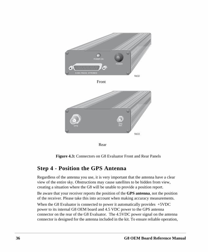
Figure 4.3: Connectors on G8 Evaluator Front and Rear Panels
Front
Rear
G8 OEM Board Reference Manual
Evaluation
Evaluation K
it
.,
ate.
t
you
simply connect the antenna to the antenna connector and locate the antenna such that it has a clear view of the entire sky.
“Clear view of the entire sky” means exactly that. Locating the antenna on top of your computer monitor inside your office does not provide a clear view of the sky. Moving it to a window may help, but the window provides only a partial view of the sky. Generally, for optimum operation your antenna must be outside, away from any natural or man-made object that obstructs or reflects radio frequency signals. Failure to locate the antenna with a clear view of the sky will impact G8 start time and accuracy.
Step 5 - Power On the Equipment
Once you have completed steps 1 through 4, you are ready to power on your equipment. Ensure that, if you are using your own antenna, it meets the specifications listed in Table 1.6 on page 8, and it operates at 4.5 VDC. If it does not operate at 4.5 VDC, you must provide the correct voltage and must have installed a DC block between the SMA connector on the G8 Evaluator rear panel and your antenna cable.
Connect the power cable to a power source. If the PWR ON light on the front panel of the G8 Evaluator is not lit, push the POWER button. The PWR ON light should now be lit.
When the G8 Evaluator is turned on for the first time, be aware of the following conditions:
1. The first power-on may require that G8 search several minutes to lock on to enough satellites to compute a position, assuming the antenna has a clear view of the entire sky. If the antenna is obstructed, the initial start may take longer to acquire satellites. “Cold starts” will typically take around 2 minutes.
2. The G8 serial interface turns on at 4800 baud. Your external device (e.gP.C.) must initially communicate with the G8 at this rate. After communication is established, you can use the PC to change the baud r
3. Once the G8 is powered on and has completed its initial start process, iimmediately begins calculating position. For firmware revision HC00 or earlier, the G8 default power-on configuration is NO OUTPUT MESSAGES. To output position messages, you must turn on the outputs
CAUTION
If the G8 has a valid Almanac and ephemeris, but has retained a last known position more than 1000 km from its actual location, the receiver should be reset using the $PASHS,INI command to minimize start time. If not reset, this condition may cause a long delay in the start time of the receiver.
and Development Kit 37
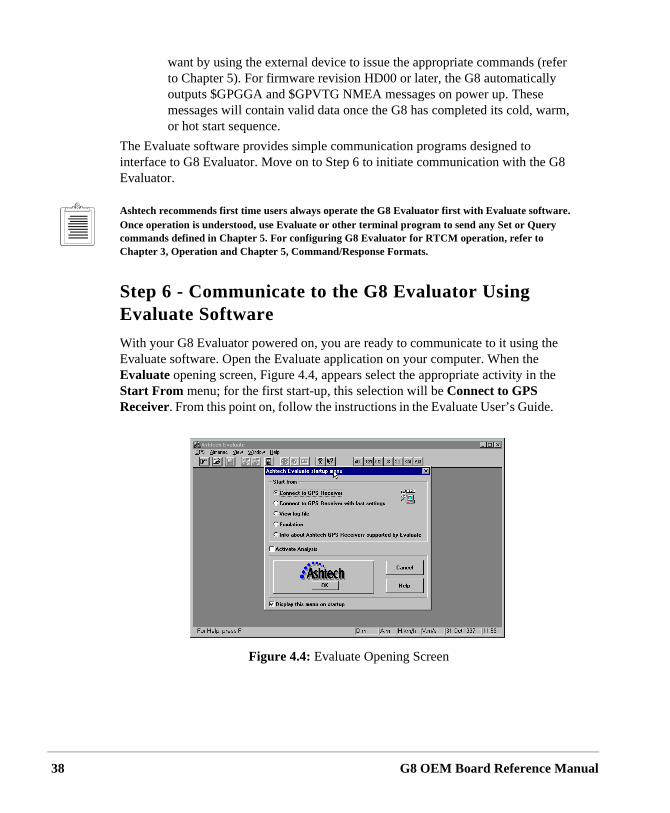
38
want by using the external device to issue the appropriate commands (refer to Chapter 5). For firmware revision HD00 or later, the G8 automatically outputs $GPGGA and $GPVTG NMEA messages on power up. These messages will contain valid data once the G8 has completed its cold, warm, or hot start sequence.
The Evaluate software provides simple communication programs designed to interface to G8 Evaluator. Move on to Step 6 to initiate communication with the G8 Evaluator.
Ashtech recommends first time users always operate the G8 Evaluator first with Evaluate software. Once operation is understood, use Evaluate or other terminal program to send any Set or Query commands defined in Chapter 5. For configuring G8 Evaluator for RTCM operation, refer to Chapter 3, Operation and Chapter 5, Command/Response Formats.
Step 6 - Communicate to the G8 Evaluator Using Evaluate Software
With your G8 Evaluator powered on, you are ready to communicate to it using the Evaluate software. Open the Evaluate application on your computer. When the Evaluate opening screen, Figure 4.4, appears select the appropriate activity in the Start From menu; for the first start-up, this selection will be Connect to GPS Receiver. From this point on, follow the instructions in the Evaluate User’s Guide.
Figure 4.4: Evaluate Opening Screen
G8 OEM Board Reference Manual
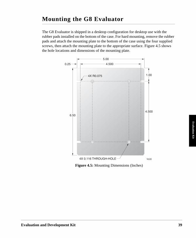
Evaluation
Evaluation K
it
Mounting the G8 Evaluator
The G8 Evaluator is shipped in a desktop configuration for desktop use with the rubber pads installed on the bottom of the case. For hard mounting, remove the rubber pads and attach the mounting plate to the bottom of the case using the four supplied screws, then attach the mounting plate to the appropriate surface. Figure 4.5 shows the hole locations and dimensions of the mounting plate.
Figure 4.5: Mounting Dimensions (Inches)
and Development Kit 39
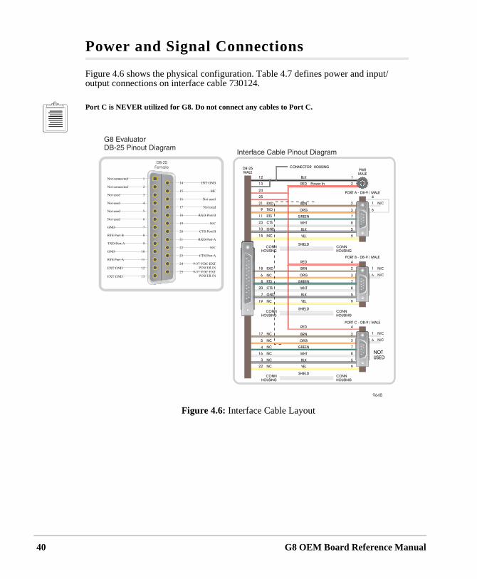
40
Power and Signal Connections
Figure 4.6 shows the physical configuration. Table 4.7 defines power and input/output connections on interface cable 730124.
Port C is NEVER utilized for G8. Do not connect any cables to Port C.
Figure 4.6: Interface Cable Layout
G8 OEM Board Reference Manual
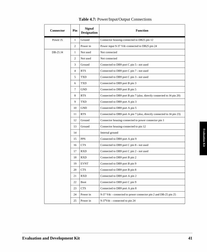
Evaluation
Evaluation K
it
Table 4.7: Power/Input/Output Connections
Connector PinSignal
DesignationFunction
Power J5 1 Ground Connector housing-connected to DB25 pin 12
2 Power in Power input 9-37 Vdc-connected to DB25 pin 24
DB-25 J4 1 Not used Not connected
2 Not used Not connected
3 Ground Connected to DB9 port C pin 5 - not used
4 RTS Connected to DB9 port C pin 7 - not used
5 TXD Connected to DB9 port C pin 3 - not used
6 TXD Connected to DB9 port B pin 3
7 GND Connected to DB9 port B pin 5
8 RTS Connected to DB9 port B pin 7 (also, directly connected to J4 pin 20)
9 TXD Connected to DB9 port A pin 3
10 GND Connected to DB9 port A pin 5
11 RTS Connected to DB9 port A pin 7 (also, directly connected to J4 pin 23)
12 Ground Connector housing-connected to power connector pin 1
13 Ground Connector housing-connected to pin 12
14 Internal ground
15 PPS Connected to DB9 port A pin 9
16 CTS Connected to DB9 port C pin 8 - not used
17 RXD Connected to DB9 port C pin 2 - not used
18 RXD Connected to DB9 port B pin 2
19 EVNT Connected to DB9 port B pin 9
20 CTS Connected to DB9 port B pin 8
21 RXD Connected to DB9 port A pin 2
22 Boot Connected to DB9 port C pin 9
23 CTS Connected to DB9 port A pin 8
24 Power in 9-37 Vdc - connected to power connector pin 2 and DB-25 pin 25
25 Power in 9-37Vdc - connected to pin 24
and Development Kit 41
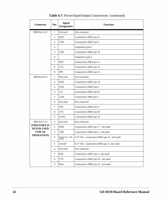
42
DB9-Port A J1 1 Not used Not connected
2 RXD Connected to DB25 pin 21
3 TXD Connected to DB25 pin 9
4 Jumpered to pin 6
5 GND Connected to DB25 pin 10
6 Jumpered to pin 4
7 RTS Connected to DB25 pin 11
8 CTS Connected to DB25 pin 23
9 PPS Connected to DB25 pin 15
DB9-Port B J2 1 Not used Not connected
2 RXD Connected to DB25 pin 18
3 TXD Connected to DB25 pin 6
4 Vcc Connected to DB25 pin 25
5 GND Connected to DB25 pin 7
6 Not used Not connected
7 RTS Connected to DB25 pin 8
8 CTS Connected to DB25 pin 20
9 EVNT Connected to DB25 pin 19
DB9-Port C J3
(THIS PORT IS NEVER USED
FOR G8 OPERATION)
1 Not used Not connected
2 RXD Connected to DB25 pin 17 - not used
3 TXD Connected to DB25 pin 5 - not used
4 Power in - not used
9-37 Vdc - connected to DB25 pin 25 - not used
5 Ground 9-37 Vdc - connected to DB25 pin 3 - not used
6 Not used Not connected
7 RTS Connected to DB25 pin 4 - not used
8 CTS Connected to DB25 pin 16 - not used
9 Boot Connected to DB25 pin 22 - not used
Table 4.7: Power/Input/Output Connections (continued)
Connector PinSignal
DesignationFunction
G8 OEM Board Reference Manual
5
Command/Response FormatsCom
mands
Command/
e and eiver er
tput. egin SHS ands ired, end
r page
fault, ype of ither is
are as
Overview
This chapter details the formats and content of the serial port commands through which the receiver is controlled and monitored. These serial port commands set receiver parameters and request data and receiver status information. Use the program REMOTE.exe software or any other standard serial communication software (including Ashtech’s Evaluate Software) to send and receive messages. Note that the baud ratprotocol of the computer COM port must match the baud rate and protocol of the recport for commands and data to be successfully transmitted and received. The receivdefault protocol setting is 8 data bits, 1 stop bit, no parity, and 4800 baud.
All commands sent by the user to the receiver are either Set commands or Query commands. Set commands generally change receiver parameters and initiate data ouQuery commands generally request receiver status information. All set commands bwith the string $PASHS and all query commands begin with the $PASHQ string. $PAand $PASHQ are the message header and are required for all commands. All commmust end with <enter> or <CR><LF> to transmit the command to the receiver. If desan optional checksum may precede the <enter> characters. All response messageswith a <CR><LF>.
The serial commands are presented in three separate groups:
• General Receiver commands - relate to general receiver operations. The discussion of these commands begins on page 47.
• NMEA message commands - control standard NMEA data message output oNMEA style message output. The discussion of these commands begins on67.
• RTCM commands - control RTCM differential operation. The discussion of these commands begins on page 92.
Within each group, the commands are listed alphabetically and described in detail. Information about the command includes the syntax, a description, the range and deand an example of how the command is used. The syntax includes the number and tparameters that are used or required by the command. These parameters may be echaracters or numbers depending upon the particular command. The parameter typeindicated by the symbol that is a part of the syntax. The formats of these parametersdefined in Table 5.1.
Response Formats 45
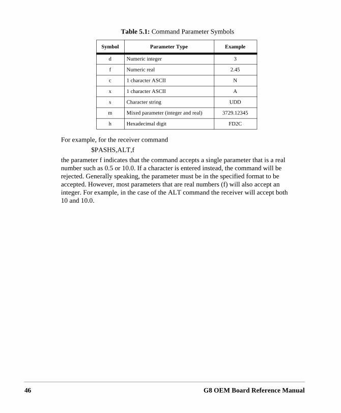
46
For example, for the receiver command
$PASHS,ALT,f
the parameter f indicates that the command accepts a single parameter that is a real number such as 0.5 or 10.0. If a character is entered instead, the command will be rejected. Generally speaking, the parameter must be in the specified format to be accepted. However, most parameters that are real numbers (f) will also accept an integer. For example, in the case of the ALT command the receiver will accept both 10 and 10.0.
Table 5.1: Command Parameter Symbols
Symbol Parameter Type Example
d Numeric integer 3
f Numeric real 2.45
c 1 character ASCII N
x 1 character ASCII A
s Character string UDD
m Mixed parameter (integer and real) 3729.12345
h Hexadecimal digit FD2C
G8 OEM Board Reference Manual
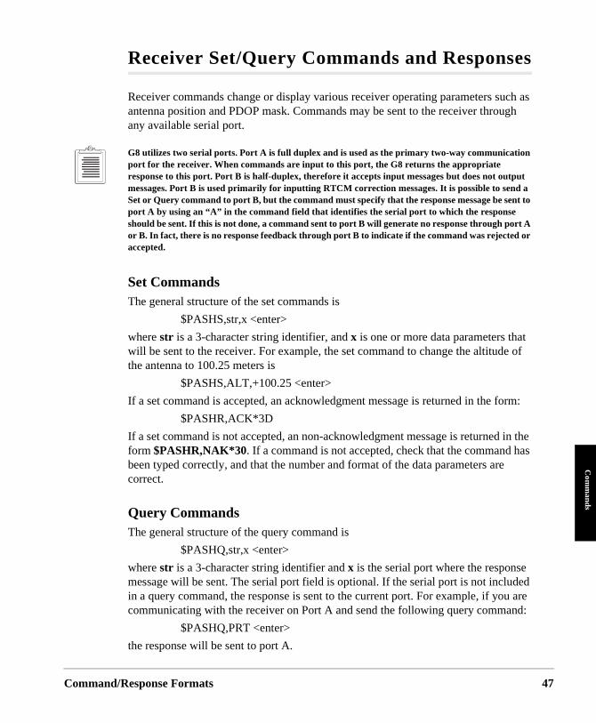
Command/
Com
mands
Receiver Set/Query Commands and Responses
Receiver commands change or display various receiver operating parameters such as antenna position and PDOP mask. Commands may be sent to the receiver through any available serial port.
G8 utilizes two serial ports. Port A is full duplex and is used as the primary two-way communication port for the receiver. When commands are input to this port, the G8 returns the appropriate response to this port. Port B is half-duplex, therefore it accepts input messages but does not output messages. Port B is used primarily for inputting RTCM correction messages. It is possible to send a Set or Query command to port B, but the command must specify that the response message be sent to port A by using an “A” in the command field that identifies the serial port to which the response should be sent. If this is not done, a command sent to port B will generate no response through port Aor B. In fact, there is no response feedback through port B to indicate if the command was rejected oraccepted.
Set CommandsThe general structure of the set commands is
$PASHS,str,x <enter>
where str is a 3-character string identifier, and x is one or more data parameters that will be sent to the receiver. For example, the set command to change the altitude of the antenna to 100.25 meters is
$PASHS,ALT,+100.25 <enter>
If a set command is accepted, an acknowledgment message is returned in the form:
$PASHR,ACK*3D
If a set command is not accepted, an non-acknowledgment message is returned in the form $PASHR,NAK*30. If a command is not accepted, check that the command has been typed correctly, and that the number and format of the data parameters are correct.
Query CommandsThe general structure of the query command is
$PASHQ,str,x <enter>
where str is a 3-character string identifier and x is the serial port where the response message will be sent. The serial port field is optional. If the serial port is not included in a query command, the response is sent to the current port. For example, if you are communicating with the receiver on Port A and send the following query command:
$PASHQ,PRT <enter>
the response will be sent to port A.
Response Formats 47
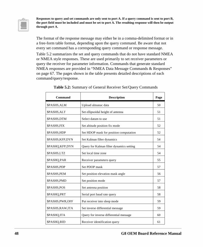
48
es”
Responses to query and set commands are only sent to port A. If a query command is sent to port B, the port field must be included and must be set to port A. The resulting response will then be output through port A.
The format of the response message may either be in a comma-delimited format or in a free-form table format, depending upon the query command. Be aware that not every set command has a corresponding query command or response message.
Table 5.2 summarizes the set and query commands that do not have standard NMEA or NMEA style responses. These are used primarily to set receiver parameters or query the receiver for parameter information. Commands that generate standard NMEA responses are provided in “NMEA Data Message Commands & Responson page 67. The pages shown in the table presents detailed descriptions of eachcommand/query/response.
Table 5.2: Summary of General Receiver Set/Query Commands
Command Description Page
$PASHS,ALM Upload almanac data 50
$PASHS,ALT Set ellipsoidal height of antenna 51
$PASHS,DTM Select datum to use 51
$PASHS,FIX Set altitude position fix mode 52
$PASHS,HDP Set HDOP mask for position computation 52
$PASHS,KFP,DYN Set Kalman filter dynamics 54
$PASHQ,KFP,DYN Query for Kalman filter dynamics setting 54
$PASHS,LTZ Set local time zone 54
$PASHQ,PAR Receiver parameters query 55
$PASHS,PDP Set PDOP mask 57
$PASHS,PEM Set position elevation mask angle 56
$PASHS,PMD Set position mode 57
$PASHS,POS Set antenna position 58
$PASHQ,PRT Serial port baud rate query 58
$PASHS,PWR,OFF Put receiver into sleep mode 59
$PASHS,RAW,ITA Set inverse differential message 59
$PASHQ,ITA Query for inverse differential message 60
$PASHQ,RID Receiver identification query 61
G8 OEM Board Reference Manual
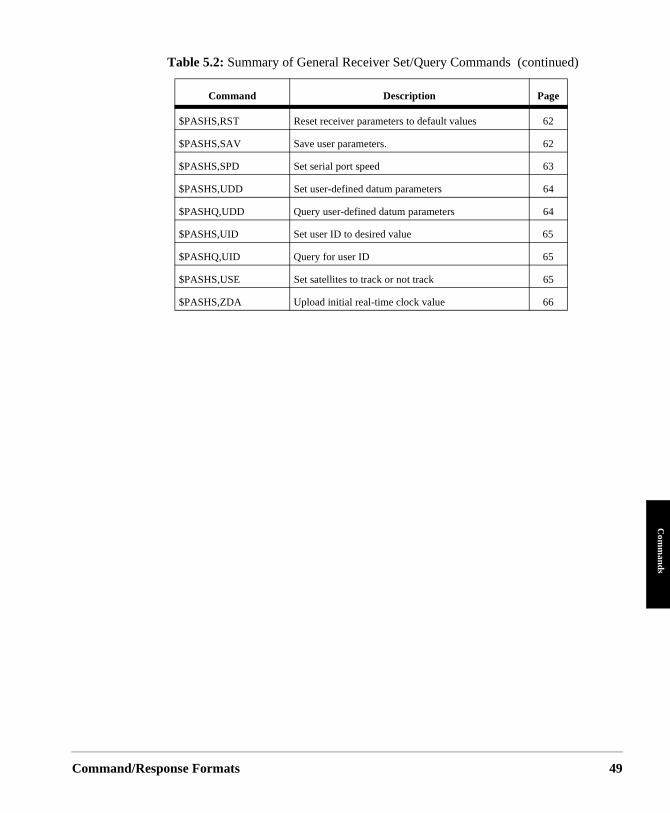
Command/
Com
mands
$PASHS,RST Reset receiver parameters to default values 62
$PASHS,SAV Save user parameters. 62
$PASHS,SPD Set serial port speed 63
$PASHS,UDD Set user-defined datum parameters 64
$PASHQ,UDD Query user-defined datum parameters 64
$PASHS,UID Set user ID to desired value 65
$PASHQ,UID Query for user ID 65
$PASHS,USE Set satellites to track or not track 65
$PASHS,ZDA Upload initial real-time clock value 66
Table 5.2: Summary of General Receiver Set/Query Commands (continued)
Command Description Page
Response Formats 49
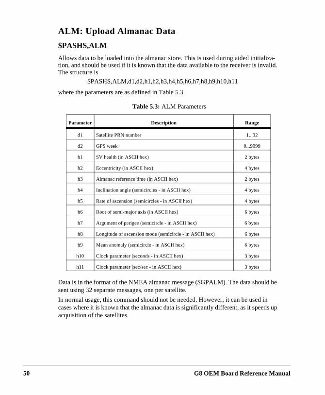
50
ALM: Upload Almanac Data
$PASHS,ALM
Allows data to be loaded into the almanac store. This is used during aided initializa-tion, and should be used if it is known that the data available to the receiver is invalid. The structure is
$PASHS,ALM,d1,d2,h1,h2,h3,h4,h5,h6,h7,h8,h9,h10,h11
where the parameters are as defined in Table 5.3.
Data is in the format of the NMEA almanac message ($GPALM). The data should be sent using 32 separate messages, one per satellite.
In normal usage, this command should not be needed. However, it can be used in cases where it is known that the almanac data is significantly different, as it speeds up acquisition of the satellites.
Table 5.3: ALM Parameters
Parameter Description Range
d1 Satellite PRN number 1...32
d2 GPS week 0...9999
h1 SV health (in ASCII hex) 2 bytes
h2 Eccentricity (in ASCII hex) 4 bytes
h3 Almanac reference time (in ASCII hex) 2 bytes
h4 Inclination angle (semicircles - in ASCII hex) 4 bytes
h5 Rate of ascension (semicircles - in ASCII hex) 4 bytes
h6 Root of semi-major axis (in ASCII hex) 6 bytes
h7 Argument of perigee (semicircle - in ASCII hex) 6 bytes
h8 Longitude of ascension mode (semicircle - in ASCII hex) 6 bytes
h9 Mean anomaly (semicircle - in ASCII hex) 6 bytes
h10 Clock parameter (seconds - in ASCII hex) 3 bytes
h11 Clock parameter (sec/sec - in ASCII hex) 3 bytes
G8 OEM Board Reference Manual
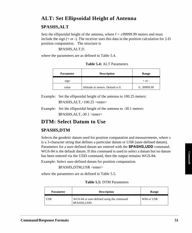
Command/
Com
mands
t 2-D
here s m).
atum
ALT: Set Ellipsoidal Height of Antenna
$PASHS,ALT
Sets the ellipsoidal height of the antenna, where f = ±99999.99 meters and musinclude the sign (+ or -). The receiver uses this data in the position calculation forposition computation. The structure is
$PASHS,ALT,f1
where the parameters are as defined in Table 5.4.
Example: Set the ellipsoidal height of the antenna to 100.25 meters:
$PASHS,ALT,+100.25 <enter>
Example: Set the ellipsoidal height of the antenna to -30.1 meters:
$PASHS,ALT,-30.1 <enter>
DTM: Select Datum to Use
$PASHS,DTM
Selects the geodetic datum used for position computation and measurements, wis a 3-character string that defines a particular datum or USR (user-defined datuParameters for a user-defined datum are entered with the $PASHS,UDD command. WGS-84 is the default datum. If this command is used to select a datum but no dhas been entered via the UDD command, then the output remains WGS-84.
Example: Select user-defined datum for position computation.
$PASHS,DTM,USR <enter>
where the parameters are as defined in Table 5.5.
Table 5.4: ALT Parameters
Parameter Description Range
sign + or -
value Altitude in meters. Default is 0. 0...99999.99
Table 5.5: DTM Parameters
Parameter Description Range
USR WGS-84 or user-defined using the command $PASHS,UDD.
W84 or USR
Response Formats 51
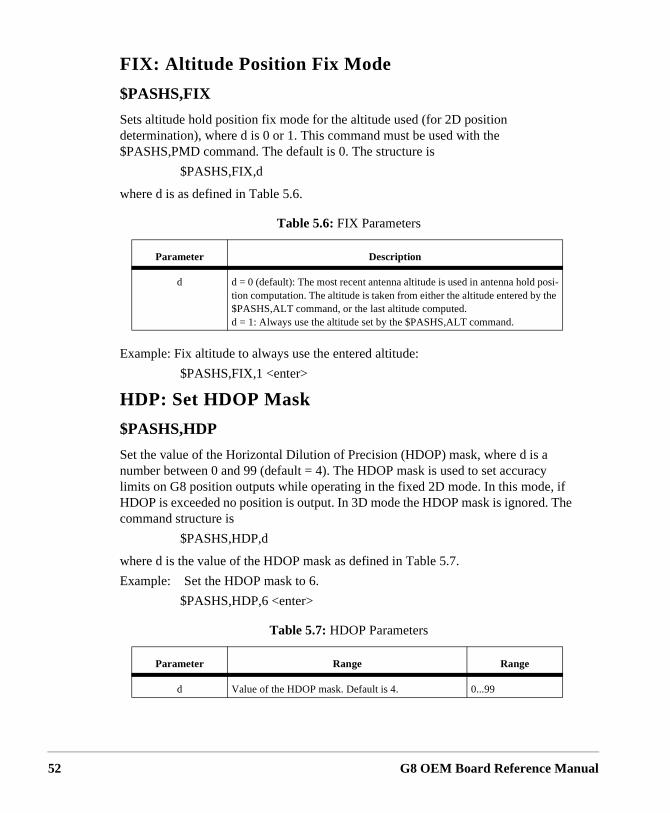
52
FIX: Altitude Position Fix Mode
$PASHS,FIX
Sets altitude hold position fix mode for the altitude used (for 2D position determination), where d is 0 or 1. This command must be used with the $PASHS,PMD command. The default is 0. The structure is
$PASHS,FIX,d
where d is as defined in Table 5.6.
Example: Fix altitude to always use the entered altitude:
$PASHS,FIX,1 <enter>
HDP: Set HDOP Mask
$PASHS,HDP
Set the value of the Horizontal Dilution of Precision (HDOP) mask, where d is a number between 0 and 99 (default = 4). The HDOP mask is used to set accuracy limits on G8 position outputs while operating in the fixed 2D mode. In this mode, if HDOP is exceeded no position is output. In 3D mode the HDOP mask is ignored. The command structure is
$PASHS,HDP,d
where d is the value of the HDOP mask as defined in Table 5.7.
Example: Set the HDOP mask to 6.
$PASHS,HDP,6 <enter>
Table 5.6: FIX Parameters
Parameter Description
d d = 0 (default): The most recent antenna altitude is used in antenna hold posi-tion computation. The altitude is taken from either the altitude entered by the $PASHS,ALT command, or the last altitude computed.d = 1: Always use the altitude set by the $PASHS,ALT command.
Table 5.7: HDOP Parameters
Parameter Range Range
d Value of the HDOP mask. Default is 4. 0...99
G8 OEM Board Reference Manual
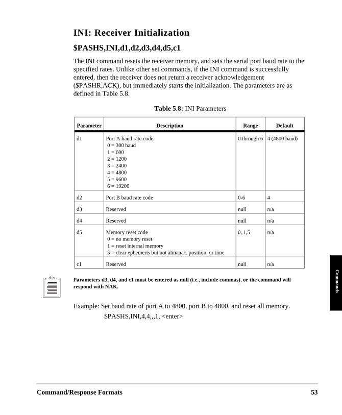
Command/
Com
mands
INI: Receiver Initialization
$PASHS,INI,d1,d2,d3,d4,d5,c1
The INI command resets the receiver memory, and sets the serial port baud rate to the specified rates. Unlike other set commands, if the INI command is successfully entered, then the receiver does not return a receiver acknowledgement ($PASHR,ACK), but immediately starts the initialization. The parameters are as defined in Table 5.8.
Parameters d3, d4, and c1 must be entered as null (i.e., include commas), or the command will respond with NAK.
Example: Set baud rate of port A to 4800, port B to 4800, and reset all memory.
$PASHS,INI,4,4,,,1, <enter>
Table 5.8: INI Parameters
Parameter Description Range Default
d1 Port A baud rate code: 0 = 300 baud 1 = 600 2 = 1200 3 = 2400 4 = 4800 5 = 9600 6 = 19200
0 through 6 4 (4800 baud)
d2 Port B baud rate code 0-6 4
d3 Reserved null n/a
d4 Reserved null n/a
d5 Memory reset code 0 = no memory reset 1 = reset internal memory 5 = clear ephemeris but not almanac, position, or time
0, 1,5 n/a
c1 Reserved null n/a
Response Formats 53
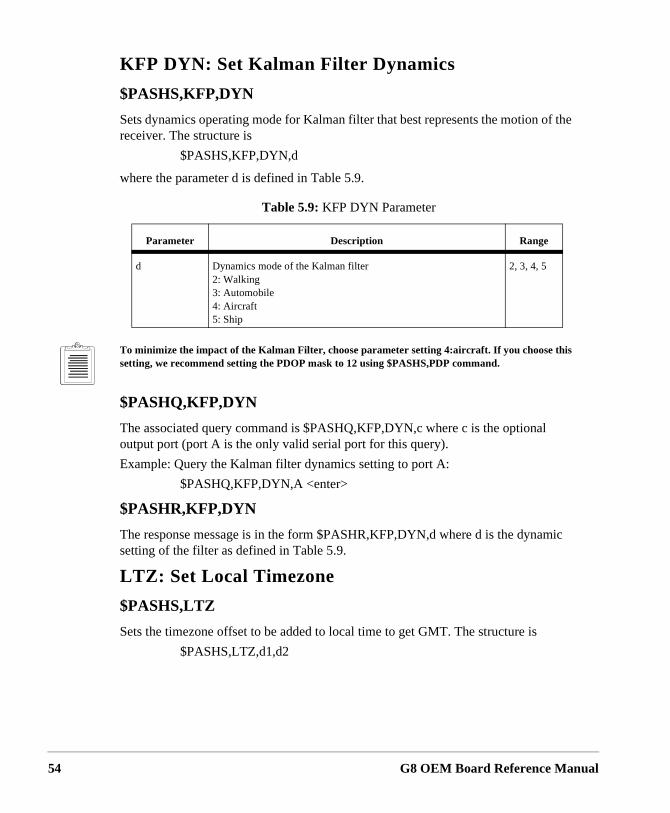
54
KFP DYN: Set Kalman Filter Dynamics
$PASHS,KFP,DYN
Sets dynamics operating mode for Kalman filter that best represents the motion of the receiver. The structure is
$PASHS,KFP,DYN,d
where the parameter d is defined in Table 5.9.
To minimize the impact of the Kalman Filter, choose parameter setting 4:aircraft. If you choose this setting, we recommend setting the PDOP mask to 12 using $PASHS,PDP command.
$PASHQ,KFP,DYN
The associated query command is $PASHQ,KFP,DYN,c where c is the optional output port (port A is the only valid serial port for this query).
Example: Query the Kalman filter dynamics setting to port A:
$PASHQ,KFP,DYN,A <enter>
$PASHR,KFP,DYN
The response message is in the form $PASHR,KFP,DYN,d where d is the dynamic setting of the filter as defined in Table 5.9.
LTZ: Set Local Timezone
$PASHS,LTZ
Sets the timezone offset to be added to local time to get GMT. The structure is
$PASHS,LTZ,d1,d2
Table 5.9: KFP DYN Parameter
Parameter Description Range
d Dynamics mode of the Kalman filter2: Walking3: Automobile4: Aircraft5: Ship
2, 3, 4, 5
G8 OEM Board Reference Manual
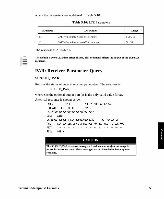
Command/
Com
mands
where the parameters are as defined in Table 5.10.
The response is ACK/NAK.
The default is 00,00 i.e. a time offset of zero. This command affects the output of the $GPZDA response.
PAR: Receiver Parameter Query
$PASHQ,PAR
Returns the status of general receiver parameters. The structure is
$PASHQ,PAR,x
where x is the optional output port (A is the only valid value for x).
A typical response is shown below.2/&����������(+:�������������2'/����2&2����*&2������
&6/�9������.6<� �������������5#8�0�
75'�;;;;;;;;;;;;;;;;;;;;;;;;;;;;;;;;�
%&5�����#761������������������������������������������������
.#6�������������0�.10��������������'������#.6� ��������
0/'#����#./�))#�)..�)5#�)58�/5)�215�4/%�5#6�7-1�86)�<&#�:/)�
246#�������������������������������������������������������
2'4�����������
Table 5.10: LTZ Parameters
Parameter Description Range
d1 GMT = localtime + timeoffset: hours ± 00...13
d2 GMT = localtime + timeoffset: minutes 00...59
CAUTION
The $PASHQ,PAR response message is free-form and subject to change in future firmware versions. These messages are not intended to be computer-readable.
Response Formats 55
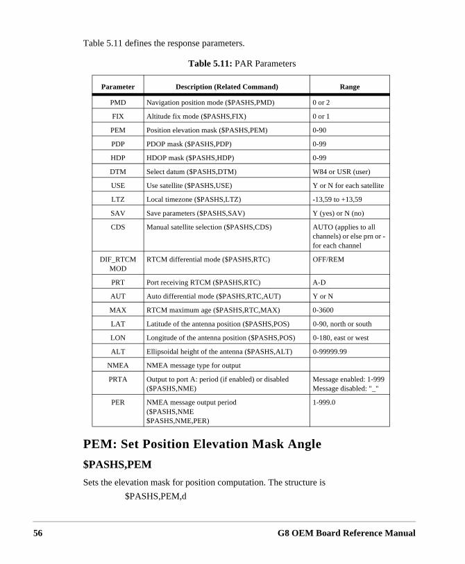
56
Table 5.11 defines the response parameters.
PEM: Set Position Elevation Mask Angle
$PASHS,PEM
Sets the elevation mask for position computation. The structure is
$PASHS,PEM,d
Table 5.11: PAR Parameters
Parameter Description (Related Command) Range
PMD Navigation position mode ($PASHS,PMD) 0 or 2
FIX Altitude fix mode ($PASHS,FIX) 0 or 1
PEM Position elevation mask ($PASHS,PEM) 0-90
PDP PDOP mask ($PASHS,PDP) 0-99
HDP HDOP mask ($PASHS,HDP) 0-99
DTM Select datum ($PASHS,DTM) W84 or USR (user)
USE Use satellite ($PASHS,USE) Y or N for each satellite
LTZ Local timezone ($PASHS,LTZ) -13,59 to +13,59
SAV Save parameters ($PASHS,SAV) Y (yes) or N (no)
CDS Manual satellite selection ($PASHS,CDS) AUTO (applies to all channels) or else prn or - for each channel
DIF_RTCM MOD
RTCM differential mode ($PASHS,RTC) OFF/REM
PRT Port receiving RTCM ($PASHS,RTC) A-D
AUT Auto differential mode ($PASHS,RTC,AUT) Y or N
MAX RTCM maximum age ($PASHS,RTC,MAX) 0-3600
LAT Latitude of the antenna position ($PASHS,POS) 0-90, north or south
LON Longitude of the antenna position ($PASHS,POS) 0-180, east or west
ALT Ellipsoidal height of the antenna ($PASHS,ALT) 0-99999.99
NMEA NMEA message type for output
PRTA Output to port A: period (if enabled) or disabled ($PASHS,NME)
Message enabled: 1-999Message disabled: "_"
PER NMEA message output period ($PASHS,NME$PASHS,NME,PER)
1-999.0
G8 OEM Board Reference Manual
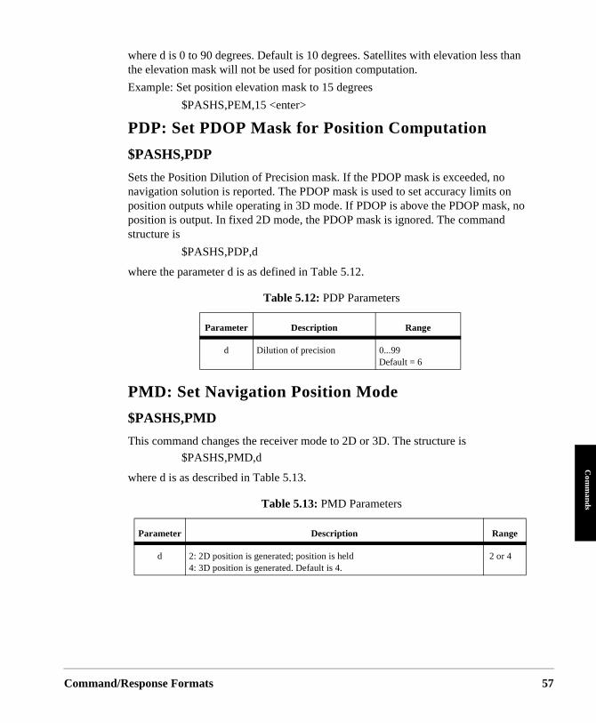
Command/
Com
mands
where d is 0 to 90 degrees. Default is 10 degrees. Satellites with elevation less than the elevation mask will not be used for position computation.
Example: Set position elevation mask to 15 degrees
$PASHS,PEM,15 <enter>
PDP: Set PDOP Mask for Position Computation
$PASHS,PDP
Sets the Position Dilution of Precision mask. If the PDOP mask is exceeded, no navigation solution is reported. The PDOP mask is used to set accuracy limits on position outputs while operating in 3D mode. If PDOP is above the PDOP mask, no position is output. In fixed 2D mode, the PDOP mask is ignored. The command structure is
$PASHS,PDP,d
where the parameter d is as defined in Table 5.12.
PMD: Set Navigation Position Mode
$PASHS,PMD
This command changes the receiver mode to 2D or 3D. The structure is
$PASHS,PMD,d
where d is as described in Table 5.13.
Table 5.12: PDP Parameters
Parameter Description Range
d Dilution of precision 0...99Default = 6
Table 5.13: PMD Parameters
Parameter Description Range
d 2: 2D position is generated; position is held4: 3D position is generated. Default is 4.
2 or 4
Response Formats 57
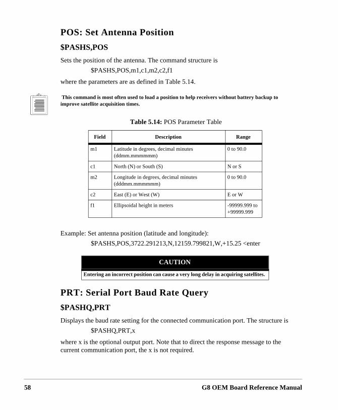
58
POS: Set Antenna Position
$PASHS,POS
Sets the position of the antenna. The command structure is
$PASHS,POS,m1,c1,m2,c2,f1
where the parameters are as defined in Table 5.14.
This command is most often used to load a position to help receivers without battery backup to improve satellite acquisition times.
Example: Set antenna position (latitude and longitude):
$PASHS,POS,3722.291213,N,12159.799821,W,+15.25 <enter
PRT: Serial Port Baud Rate Query
$PASHQ,PRT
Displays the baud rate setting for the connected communication port. The structure is
$PASHQ,PRT,x
where x is the optional output port. Note that to direct the response message to the current communication port, the x is not required.
Table 5.14: POS Parameter Table
Field Description Range
m1 Latitude in degrees, decimal minutes(ddmm.mmmmmm)
0 to 90.0
c1 North (N) or South (S) N or S
m2 Longitude in degrees, decimal minutes(dddmm.mmmmmm)
0 to 90.0
c2 East (E) or West (W) E or W
f1 Ellipsoidal height in meters -99999.999 to +99999.999
CAUTION
Entering an incorrect position can cause a very long delay in acquiring satellites.
G8 OEM Board Reference Manual
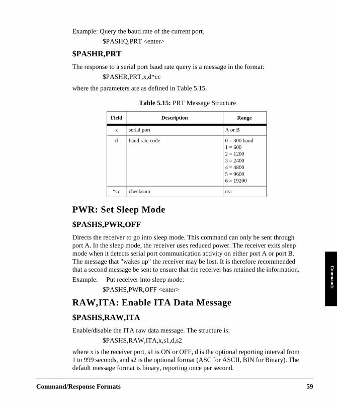
Command/
Com
mands
Example: Query the baud rate of the current port.
$PASHQ,PRT <enter>
$PASHR,PRT
The response to a serial port baud rate query is a message in the format:
$PASHR,PRT,x,d*cc
where the parameters are as defined in Table 5.15.
PWR: Set Sleep Mode
$PASHS,PWR,OFF
Directs the receiver to go into sleep mode. This command can only be sent through port A. In the sleep mode, the receiver uses reduced power. The receiver exits sleep mode when it detects serial port communication activity on either port A or port B. The message that "wakes up" the receiver may be lost. It is therefore recommended that a second message be sent to ensure that the receiver has retained the information.
Example: Put receiver into sleep mode:
$PASHS,PWR,OFF <enter>
RAW,ITA: Enable ITA Data Message
$PASHS,RAW,ITA
Enable/disable the ITA raw data message. The structure is:
$PASHS,RAW,ITA,x,s1,d,s2
where x is the receiver port, s1 is ON or OFF, d is the optional reporting interval from 1 to 999 seconds, and s2 is the optional format (ASC for ASCII, BIN for Binary). The default message format is binary, reporting once per second.
Table 5.15: PRT Message Structure
Field Description Range
x serial port A or B
d baud rate code 0 = 300 baud1 = 600 2 = 1200 3 = 24004 = 4800 5 = 96006 = 19200
*cc checksum n/a
Response Formats 59
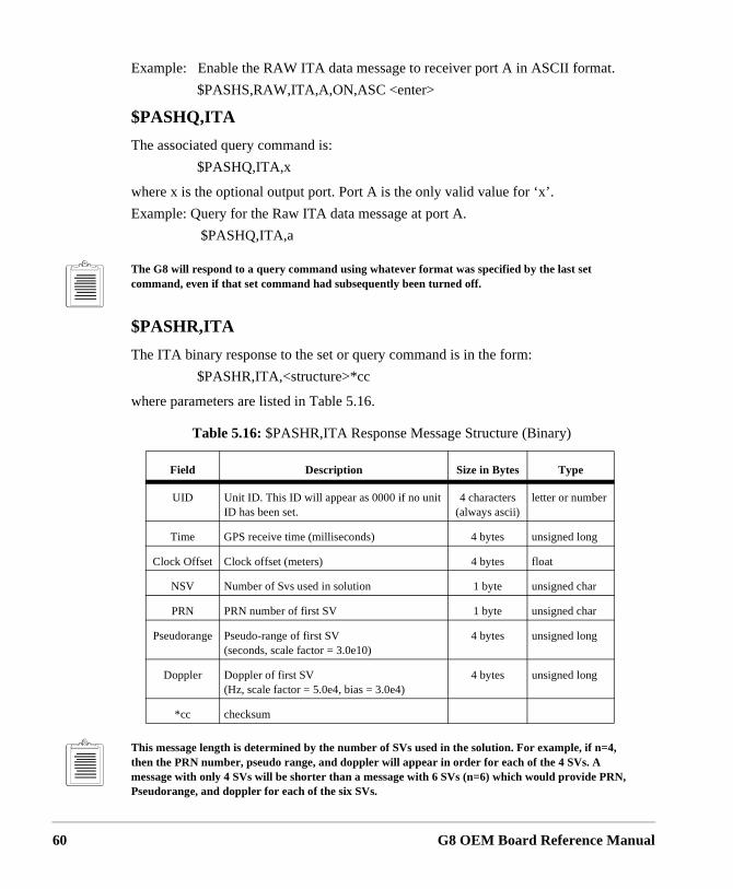
60
Example: Enable the RAW ITA data message to receiver port A in ASCII format.
$PASHS,RAW,ITA,A,ON,ASC <enter>
$PASHQ,ITA
The associated query command is:
$PASHQ,ITA,x
where x is the optional output port. Port A is the only valid value for ‘x’.
Example: Query for the Raw ITA data message at port A.
$PASHQ,ITA,a
The G8 will respond to a query command using whatever format was specified by the last set command, even if that set command had subsequently been turned off.
$PASHR,ITA
The ITA binary response to the set or query command is in the form:
$PASHR,ITA,<structure>*cc
where parameters are listed in Table 5.16.
This message length is determined by the number of SVs used in the solution. For example, if n=4, then the PRN number, pseudo range, and doppler will appear in order for each of the 4 SVs. A message with only 4 SVs will be shorter than a message with 6 SVs (n=6) which would provide PRN, Pseudorange, and doppler for each of the six SVs.
Table 5.16: $PASHR,ITA Response Message Structure (Binary)
Field Description Size in Bytes Type
UID Unit ID. This ID will appear as 0000 if no unit ID has been set.
4 characters (always ascii)
letter or number
Time GPS receive time (milliseconds) 4 bytes unsigned long
Clock Offset Clock offset (meters) 4 bytes float
NSV Number of Svs used in solution 1 byte unsigned char
PRN PRN number of first SV 1 byte unsigned char
Pseudorange Pseudo-range of first SV(seconds, scale factor = 3.0e10)
4 bytes unsigned long
Doppler Doppler of first SV(Hz, scale factor = 5.0e4, bias = 3.0e4)
4 bytes unsigned long
*cc checksum
G8 OEM Board Reference Manual
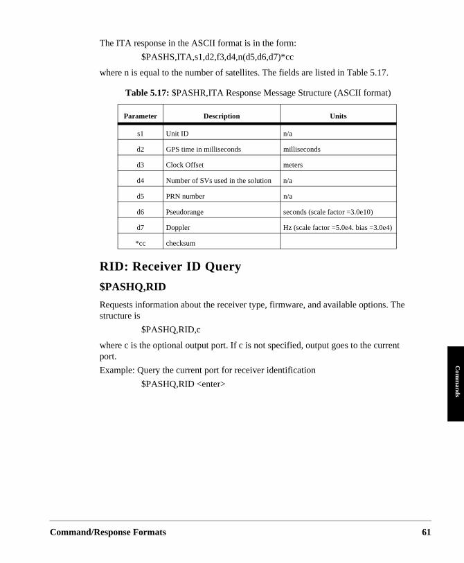
Command/
Com
mands
The ITA response in the ASCII format is in the form:
$PASHS,ITA,s1,d2,f3,d4,n(d5,d6,d7)*cc
where n is equal to the number of satellites. The fields are listed in Table 5.17.
RID: Receiver ID Query
$PASHQ,RID
Requests information about the receiver type, firmware, and available options. The structure is
$PASHQ,RID,c
where c is the optional output port. If c is not specified, output goes to the current port.
Example: Query the current port for receiver identification
$PASHQ,RID <enter>
Table 5.17: $PASHR,ITA Response Message Structure (ASCII format)
Parameter Description Units
s1 Unit ID n/a
d2 GPS time in milliseconds milliseconds
d3 Clock Offset meters
d4 Number of SVs used in the solution n/a
d5 PRN number n/a
d6 Pseudorange seconds (scale factor =3.0e10)
d7 Doppler Hz (scale factor =5.0e4. bias =3.0e4)
*cc checksum
Response Formats 61
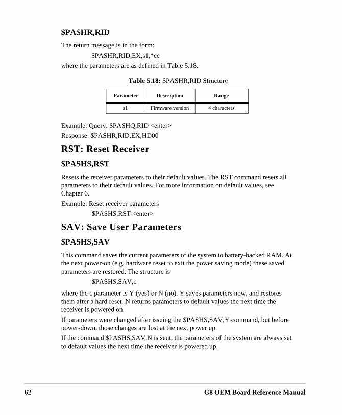
62
$PASHR,RID
The return message is in the form:
$PASHR,RID,EX,s1,*cc
where the parameters are as defined in Table 5.18.
Example: Query: $PASHQ,RID <enter>
Response: $PASHR,RID,EX,HD00
RST: Reset Receiver
$PASHS,RST
Resets the receiver parameters to their default values. The RST command resets all parameters to their default values. For more information on default values, see Chapter 6.
Example: Reset receiver parameters
$PASHS,RST <enter>
SAV: Save User Parameters
$PASHS,SAV
This command saves the current parameters of the system to battery-backed RAM. At the next power-on (e.g. hardware reset to exit the power saving mode) these saved parameters are restored. The structure is
$PASHS,SAV,c
where the c parameter is Y (yes) or N (no). Y saves parameters now, and restores them after a hard reset. N returns parameters to default values the next time the receiver is powered on.
If parameters were changed after issuing the $PASHS,SAV,Y command, but before power-down, those changes are lost at the next power up.
If the command $PASHS,SAV,N is sent, the parameters of the system are always set to default values the next time the receiver is powered up.
Table 5.18: $PASHR,RID Structure
Parameter Description Range
s1 Firmware version 4 characters
G8 OEM Board Reference Manual
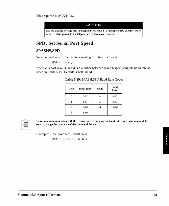
Command/
Com
mands
The response is ACK/NAK.
SPD: Set Serial Port Speed
$PASHS,SPD
Sets the baud rate of the receiver serial port. The structure is
$PASH,SPD,c,d
where c is port A or B, and d is a number between 0 and 6 specifying the baud rate as listed in Table 5.19. Default is 4800 baud.
To resume communication with the receiver after changing the baud rate using this command, be sure to change the baud rate of the command device.
Example: Set port A to 19200 baud
$PASHS,SPD,A,6 <enter>
CAUTION
Battery backup voltage must be applied to G8 pin 3 (V-back) for new parameters to be saved after power to the G8 pin (VCC) has been removed.
Table 5.19: $PASH,SPD Baud Rate Codes
Code Baud Rate CodeBaud Rate
0 300 4 4800
1 600 5 9600
2 1200 6 19200
3 2400
Response Formats 63
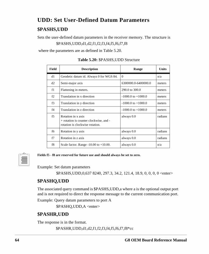
64
UDD: Set User-Defined Datum Parameters
$PASHS,UDD
Sets the user-defined datum parameters in the receiver memory. The structure is
$PASHS,UDD,d1,d2,f1,f2,f3,f4,f5,f6,f7,f8
where the parameters are as defined in Table 5.20.
Fields f5 - f8 are reserved for future use and should always be set to zero.
Example: Set datum parameters
$PASHS,UDD,0,637 8240, 297.3, 34.2, 121.4, 18.9, 0, 0, 0, 0 <enter>
$PASHQ,UDD
The associated query command is $PASHS,UDD,a where a is the optional output port and is not required to direct the response message to the current communication port.
Example: Query datum parameters to port A
$PASHQ,UDD,A <enter>
$PASHR,UDD
The response is in the format.
$PASHR,UDD,d1,d2,f1,f2,f3,f4,f5,f6,f7,f8*cc
Table 5.20: $PASHS,UDD Structure
Field Description Range Units
d1 Geodetic datum id. Always 0 for WGS 84. 0 n/a
d2 Semi-major axis 6300000.0-6400000.0 meters
f1 Flattening in meters. 290.0 to 300.0 meters
f2 Translation in x direction -1000.0 to +1000.0 meters
f3 Translation in y direction -1000.0 to +1000.0 meters
f4 Translation in z direction -1000.0 to +1000.0 meters
f5 Rotation in x axis+ rotation is counter clockwise, and - rotation is clockwise rotation.
always 0.0 radians
f6 Rotation in y axis always 0.0 radians
f7 Rotation in z axis always 0.0 radians
f8 Scale factor. Range -10.00 to +10.00. always 0.0 n/a
G8 OEM Board Reference Manual
Command/
Com
mands
where the fields are as defined in Table 5.20.
UID: Set User ID
$PASHS,UID
Sets the Unit ID for the receiver. The structure is:
$PASHS,UID,s
where s is a 4 character identification number selected by the user.
Example: Set user ID to A179
$PASHS,UID,A179
The UID set command also sets the user identification number in the POS and ITA messages.
$PASHQ,UID
The associated query command is $PASHQ,UID,c, where c is the optional output port. This query returns unit ID to the port specified. Port A is the only valid value for s.
$PASHR,UID
The response is in the format:
$PASHR,UID,d*cc
where d is the user identification number.
Example: The response to $PASHQ,UID for the ID number set in the earlier example is:
$PASHR,UID,A179
If no value has been entered through the $PASHS,UID command, then the default value (null) will be reported in the $PASHR,UID response and the $PASHR,POS response. The $PASHR,ITA response will report all zeros in the unit identification field.
USE: Set Satellites to Use
$PASHS,USE
Selects satellites to track or not track. The structure is
$PASHS,USE,d,c
where d is the PRN number of the satellite (range from 1 to 32) or ALL for all satellites, and c is Y (enable) or N (disable).
Response Formats 65
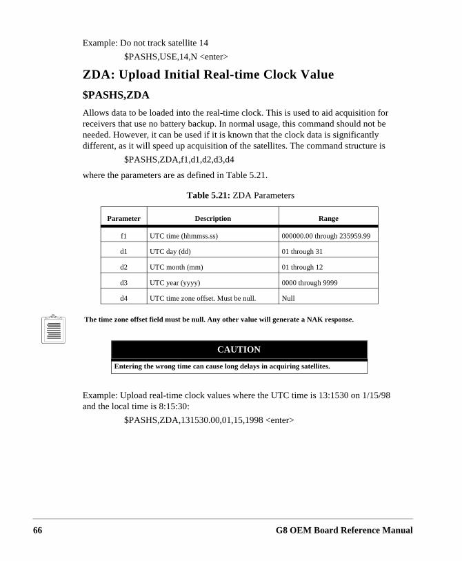
66
Example: Do not track satellite 14
$PASHS,USE,14,N <enter>
ZDA: Upload Initial Real-time Clock Value
$PASHS,ZDA
Allows data to be loaded into the real-time clock. This is used to aid acquisition for receivers that use no battery backup. In normal usage, this command should not be needed. However, it can be used if it is known that the clock data is significantly different, as it will speed up acquisition of the satellites. The command structure is
$PASHS,ZDA,f1,d1,d2,d3,d4
where the parameters are as defined in Table 5.21.
The time zone offset field must be null. Any other value will generate a NAK response.
Example: Upload real-time clock values where the UTC time is 13:1530 on 1/15/98 and the local time is 8:15:30:
$PASHS,ZDA,131530.00,01,15,1998 <enter>
Table 5.21: ZDA Parameters
Parameter Description Range
f1 UTC time (hhmmss.ss) 000000.00 through 235959.99
d1 UTC day (dd) 01 through 31
d2 UTC month (mm) 01 through 12
d3 UTC year (yyyy) 0000 through 9999
d4 UTC time zone offset. Must be null. Null
CAUTION
Entering the wrong time can cause long delays in acquiring satellites.
G8 OEM Board Reference Manual
Command/
Com
mands
NMEA Data Message Commands & Responses
The NMEA message commands control all query and set commands related to NMEA format messages and miscellaneous messages in an Ashtech NMEA style format. All standard NMEA messages are a string of ASCII characters delimited by commas, in compliance with NMEA 0183 Standard Version 2.2. All non-standard messages are a string of ASCII characters delimited by commas in the Ashtech NMEA style format. Any combination of these messages can be output as long as the character I/O rate for the receiver is not exceeded (400 characters per second). The output interval is determined by the $PASHS,NME,PER command or the specific $PASHS,NME command, and can be set to any value between 1 and 999 seconds.
For each NMEA message type there is a set command, a query command and a response message. The set command is used to continuously output the NMEA response message at the specified period. The query outputs a NMEA response message only once.
Set Commands
The general structure of the NMEA set commands is
$PASHS,NME,str,x,s,d <enter>
where x is the serial port to which the response message should be sent, s is either ON or OFF, and d is an optional parameter to specify the reporting interval. ON enables the message and OFF disables the message. The str is a 3-character string that identifies the NMEA message to be output. If the reporting interval is not set, the output interval set by the $PASHS,NME,PER command is used. The available strings are:
ALM, GGA, GLL, GSA, GSV, MSG, POS, RMC, SAT, ZDA
When a set command is sent correctly, the receiver sends a $PASHR,ACK (command acknowledge) message. If the command is sent incorrectly or the syntax is wrong, the receiver sends a $PASHS,NAK (command not acknowledged) message. Once acknowledged, the receiver will output the corresponding NMEA data message at the interval defined, unless a necessary condition for the message to be output is not present. For example, the MSG message is not output unless RTCM differential has been enabled.
Port A is the only port that can be used to output NMEA messages.
To disable all NMEA messages, use the $PASHS,NME,ALL command.
To see what NMEA messages have been enabled, use the $PASHQ,PAR command.
Response Formats 67
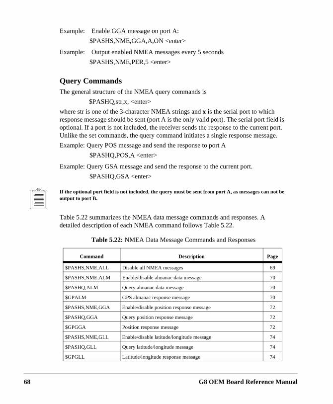
68
Example: Enable GGA message on port A:
$PASHS,NME,GGA,A,ON <enter>
Example: Output enabled NMEA messages every 5 seconds
$PASHS,NME,PER,5 <enter>
Query CommandsThe general structure of the NMEA query commands is
$PASHQ,str,x, <enter>
where str is one of the 3-character NMEA strings and x is the serial port to which response message should be sent (port A is the only valid port). The serial port field is optional. If a port is not included, the receiver sends the response to the current port. Unlike the set commands, the query command initiates a single response message.
Example: Query POS message and send the response to port A
$PASHQ,POS,A <enter>
Example: Query GSA message and send the response to the current port.
$PASHQ,GSA <enter>
If the optional port field is not included, the query must be sent from port A, as messages can not be output to port B.
Table 5.22 summarizes the NMEA data message commands and responses. A detailed description of each NMEA command follows Table 5.22.
Table 5.22: NMEA Data Message Commands and Responses
Command Description Page
$PASHS,NME,ALL Disable all NMEA messages 69
$PASHS,NME,ALM Enable/disable almanac data message 70
$PASHQ,ALM Query almanac data message 70
$GPALM GPS almanac response message 70
$PASHS,NME,GGA Enable/disable position response message 72
$PASHQ,GGA Query position response message 72
$GPGGA Position response message 72
$PASHS,NME,GLL Enable/disable latitude/longitude message 74
$PASHQ,GLL Query latitude/longitude message 74
$GPGLL Latitude/longitude response message 74
G8 OEM Board Reference Manual
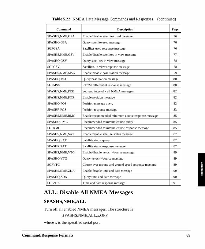
Command/
Com
mands
ALL: Disable All NMEA Messages
$PASHS,NME,ALL
Turn off all enabled NMEA messages. The structure is
$PASHS,NME,ALL,x,OFF
where x is the specified serial port.
$PASHS,NME,GSA Enable/disable satellites used message 76
$PASHQ,GSA Query satellite used message 76
$GPGSA Satellites used response message 76
$PASHS,NME,GSV Enable/disable satellites in view message 77
$PASHQ,GSV Query satellites in view message 78
$GPGSV Satellites-in-view response message 78
$PASHS,NME,MSG Enable/disable base station message 79
$PASHQ,MSG Query base station message 80
$GPMSG RTCM differential response message 80
$PASHS,NME,PER Set send interval - all NMEA messages 82
$PASHS,NME,POS Enable position message 82
$PASHQ,POS Position message query 82
$PASHR,POS Position response message 83
$PASHS,NME,RMC Enable recommended minimum course response message 85
$PASHQ,RMC Recommended minimum course query 85
$GPRMC Recommended minimum course response message 85
$PASHS,NME,SAT Enable/disable satellite status message 87
$PASHQ,SAT Satellite status query 87
$PASHR,SAT Satellite status response message 87
$PASHS,NME,VTG Enable/disable velocity/course message 89
$PASHQ,VTG Query velocity/course message 89
$GPVTG Course over ground and ground speed response message 89
$PASHS,NME,ZDA Enable/disable time and date message 90
$PASHQ,ZDA Query time and date message 90
$GPZDA Time and date response message 91
Table 5.22: NMEA Data Message Commands and Responses (continued)
Command Description Page
Response Formats 69
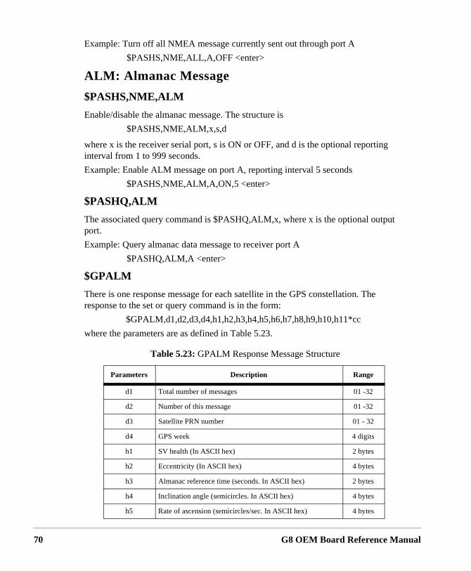
70
Example: Turn off all NMEA message currently sent out through port A
$PASHS,NME,ALL,A,OFF <enter>
ALM: Almanac Message
$PASHS,NME,ALM
Enable/disable the almanac message. The structure is
$PASHS,NME,ALM,x,s,d
where x is the receiver serial port, s is ON or OFF, and d is the optional reporting interval from 1 to 999 seconds.
Example: Enable ALM message on port A, reporting interval 5 seconds
$PASHS,NME,ALM,A,ON,5 <enter>
$PASHQ,ALM
The associated query command is $PASHQ,ALM,x, where x is the optional output port.
Example: Query almanac data message to receiver port A
$PASHQ,ALM,A <enter>
$GPALM
There is one response message for each satellite in the GPS constellation. The response to the set or query command is in the form:
$GPALM,d1,d2,d3,d4,h1,h2,h3,h4,h5,h6,h7,h8,h9,h10,h11*cc
where the parameters are as defined in Table 5.23.
Table 5.23: GPALM Response Message Structure
Parameters Description Range
d1 Total number of messages 01 -32
d2 Number of this message 01 -32
d3 Satellite PRN number 01 - 32
d4 GPS week 4 digits
h1 SV health (In ASCII hex) 2 bytes
h2 Eccentricity (In ASCII hex) 4 bytes
h3 Almanac reference time (seconds. In ASCII hex) 2 bytes
h4 Inclination angle (semicircles. In ASCII hex) 4 bytes
h5 Rate of ascension (semicircles/sec. In ASCII hex) 4 bytes
G8 OEM Board Reference Manual
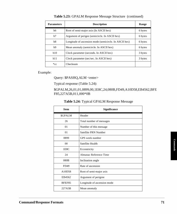
Command/
Com
mands
Example:
Query: $PASHQ,ALM <enter>
Typical response (Table 5.24):
$GPALM,26,01,01,0899,00,1E8C,24,080B,FD49,A10D58,EB4562,BFEF85,227A5B,011,000*0B
h6 Root of semi-major axis (In ASCII hex) 6 bytes
h7 Argument of perigee (semicircle. In ASCII hex) 6 bytes
h8 Longitude of ascension mode (semicircle. In ASCII hex) 6 bytes
h9 Mean anomaly (semicircle. In ASCII hex) 6 bytes
h10 Clock parameter (seconds. In ASCII hex) 3 bytes
h11 Clock parameter (sec/sec. In ASCII hex) 3 bytes
*cc Checksum
Table 5.24: Typical GPALM Response Message
Item Significance
$GPALM Header
26 Total number of messages
01 Number of this message
01 Satellite PRN Number
0899 GPS week number
00 Satellite Health
1E8C Eccentricity
24 Almanac Reference Time
080B Inclination angle
FD49 Rate of ascension
A10D58 Root of semi-major axis
EB4562 Argument of perigree
BFEF85 Longitude of ascension mode
227A5B Mean anomaly
Table 5.23: GPALM Response Message Structure (continued)
Parameters Description Range
Response Formats 71
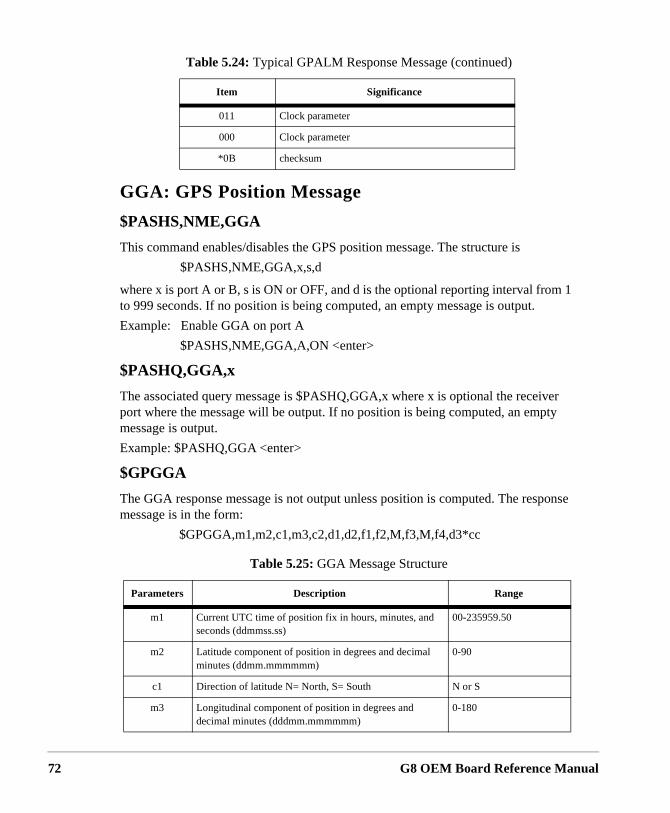
72
GGA: GPS Position Message
$PASHS,NME,GGA
This command enables/disables the GPS position message. The structure is
$PASHS,NME,GGA,x,s,d
where x is port A or B, s is ON or OFF, and d is the optional reporting interval from 1 to 999 seconds. If no position is being computed, an empty message is output.
Example: Enable GGA on port A
$PASHS,NME,GGA,A,ON <enter>
$PASHQ,GGA,x
The associated query message is $PASHQ,GGA,x where x is optional the receiver port where the message will be output. If no position is being computed, an empty message is output.
Example: $PASHQ,GGA <enter>
$GPGGA
The GGA response message is not output unless position is computed. The response message is in the form:
$GPGGA,m1,m2,c1,m3,c2,d1,d2,f1,f2,M,f3,M,f4,d3*cc
011 Clock parameter
000 Clock parameter
*0B checksum
Table 5.25: GGA Message Structure
Parameters Description Range
m1 Current UTC time of position fix in hours, minutes, and seconds (ddmmss.ss)
00-235959.50
m2 Latitude component of position in degrees and decimal minutes (ddmm.mmmmmm)
0-90
c1 Direction of latitude N= North, S= South N or S
m3 Longitudinal component of position in degrees and decimal minutes (dddmm.mmmmmm)
0-180
Table 5.24: Typical GPALM Response Message (continued)
Item Significance
G8 OEM Board Reference Manual
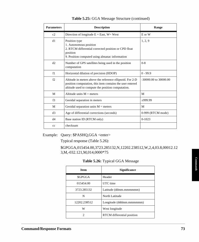
Command/
Com
mands
Example: Query: $PASHQ,GGA <enter>
Typical response (Table 5.26):
$GPGGA,015454.00,3723.285132,N,12202.238512,W,2,4,03.8,00012.123,M,-032.121,M,014,0000*75
c2 Direction of longitude E = East, W= West E or W
d1 Position type1. Autonomous position2. RTCM differential corrected position or CPD float position9. Position computed using almanac information
1, 2, 9
d2 Number of GPS satellites being used in the position computation
0-8
f1 Horizontal dilution of precision (HDOP) 0 - 99.9
f2 Altitude in meters above the reference ellipsoid. For 2-D position computation, this item contains the user entered altitude used to compute the position computation.
-30000.00 to 30000.00
M Altitude units M = meters M
f3 Geoidal separation in meters ±999.99
M Geoidal separation units M = meters M
d3 Age of differential corrections (seconds) 0-999 (RTCM mode)
d4 Base station ID (RTCM only) 0-1023
cc checksum
Table 5.26: Typical GGA Message
Item Significance
$GPGGA Header
015454.00 UTC time
3723.285132 Latitude (ddmm.mmmmmm)
N North Latitude
12202.238512 Longitude (dddmm.mmmmmm)
W West longitude
2 RTCM differential position
Table 5.25: GGA Message Structure (continued)
Parameters Description Range
Response Formats 73
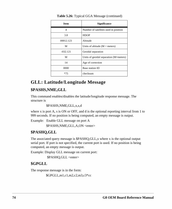
74
GLL: Latitude/Longitude Message
$PASHS,NME,GLL
This command enables/disables the latitude/longitude response message. The structure is
$PASHS,NME,GLL,x,s,d
where x is port A, s is ON or OFF, and d is the optional reporting interval from 1 to 999 seconds. If no position is being computed, an empty message is output.
Example: Enable GLL message on port A
$PASHS,NME,GLL,A,ON <enter>
$PASHQ,GLL
The associated query message is $PASHQ,GLL,x where x is the optional output serial port. If port is not specified, the current port is used. If no position is being computed, an empty message is output.
Example: Display GLL message on current port:
$PASHQ,GLL <enter>
$GPGLL
The response message is in the form:
$GPGLL,m1,c1,m2,c2,m3,c3*cc
4 Number of satellites used in position
3.8 HDOP
00012.123 Altitude
M Units of altitude (M = meters)
-032.121 Geoidal separation
M Units of geoidal separation (M=meters)
14 Age of correction
0000 Base station ID
*75 checksum
Table 5.26: Typical GGA Message (continued)
Item Significance
G8 OEM Board Reference Manual
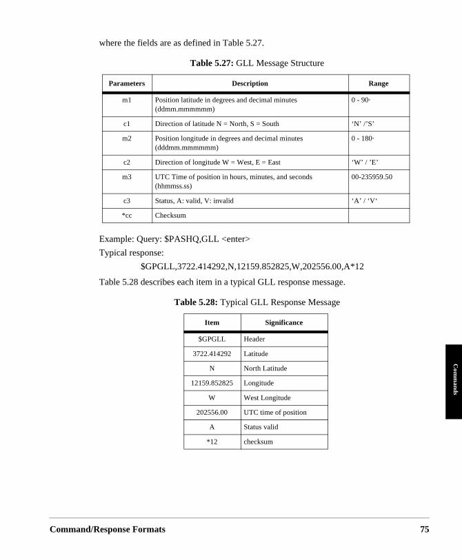
Command/
Com
mands
where the fields are as defined in Table 5.27.
Example: Query: $PASHQ,GLL <enter>
Typical response:
$GPGLL,3722.414292,N,12159.852825,W,202556.00,A*12
Table 5.28 describes each item in a typical GLL response message.
Table 5.27: GLL Message Structure
Parameters Description Range
m1 Position latitude in degrees and decimal minutes (ddmm.mmmmmm)
0 - 90°
c1 Direction of latitude N = North, S = South ‘N’ /’S’
m2 Position longitude in degrees and decimal minutes (dddmm.mmmmmm)
0 - 180°
c2 Direction of longitude W = West, E = East ‘W’ / ’E’
m3 UTC Time of position in hours, minutes, and seconds (hhmmss.ss)
00-235959.50
c3 Status, A: valid, V: invalid ‘A’ / ‘V‘
*cc Checksum
Table 5.28: Typical GLL Response Message
Item Significance
$GPGLL Header
3722.414292 Latitude
N North Latitude
12159.852825 Longitude
W West Longitude
202556.00 UTC time of position
A Status valid
*12 checksum
Response Formats 75
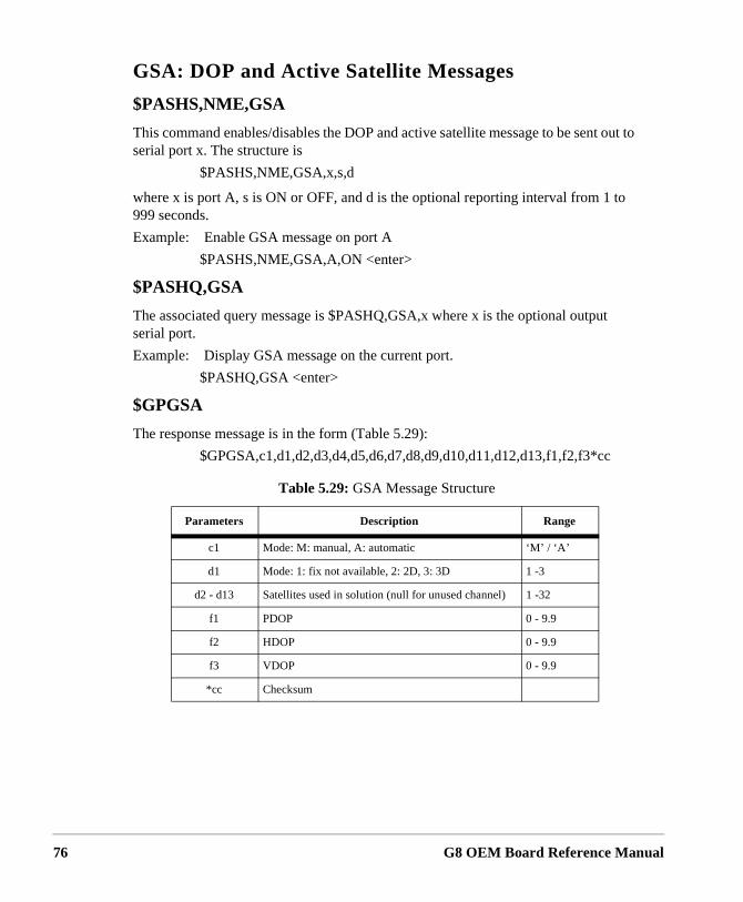
76
GSA: DOP and Active Satellite Messages
$PASHS,NME,GSA
This command enables/disables the DOP and active satellite message to be sent out to serial port x. The structure is
$PASHS,NME,GSA,x,s,d
where x is port A, s is ON or OFF, and d is the optional reporting interval from 1 to 999 seconds.
Example: Enable GSA message on port A
$PASHS,NME,GSA,A,ON <enter>
$PASHQ,GSA
The associated query message is $PASHQ,GSA,x where x is the optional output serial port.
Example: Display GSA message on the current port.
$PASHQ,GSA <enter>
$GPGSA
The response message is in the form (Table 5.29):
$GPGSA,c1,d1,d2,d3,d4,d5,d6,d7,d8,d9,d10,d11,d12,d13,f1,f2,f3*cc
Table 5.29: GSA Message Structure
Parameters Description Range
c1 Mode: M: manual, A: automatic ‘M’ / ‘A’
d1 Mode: 1: fix not available, 2: 2D, 3: 3D 1 -3
d2 - d13 Satellites used in solution (null for unused channel) 1 -32
f1 PDOP 0 - 9.9
f2 HDOP 0 - 9.9
f3 VDOP 0 - 9.9
*cc Checksum
G8 OEM Board Reference Manual
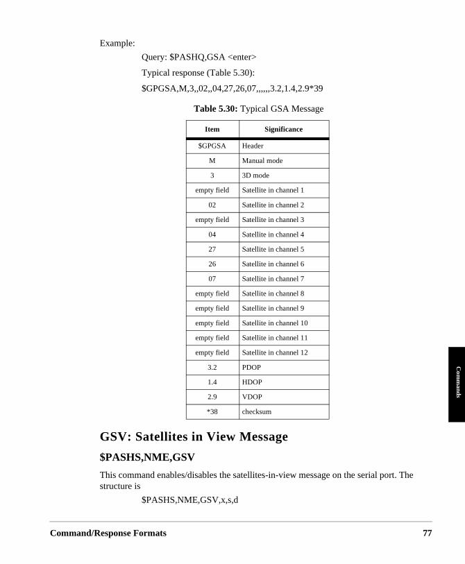
Command/
Com
mands
Example:
Query: $PASHQ,GSA <enter>
Typical response (Table 5.30):
$GPGSA,M,3,,02,,04,27,26,07,,,,,,3.2,1.4,2.9*39
GSV: Satellites in View Message
$PASHS,NME,GSV
This command enables/disables the satellites-in-view message on the serial port. The structure is
$PASHS,NME,GSV,x,s,d
Table 5.30: Typical GSA Message
Item Significance
$GPGSA Header
M Manual mode
3 3D mode
empty field Satellite in channel 1
02 Satellite in channel 2
empty field Satellite in channel 3
04 Satellite in channel 4
27 Satellite in channel 5
26 Satellite in channel 6
07 Satellite in channel 7
empty field Satellite in channel 8
empty field Satellite in channel 9
empty field Satellite in channel 10
empty field Satellite in channel 11
empty field Satellite in channel 12
3.2 PDOP
1.4 HDOP
2.9 VDOP
*38 checksum
Response Formats 77
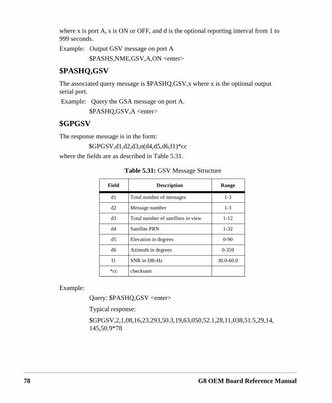
78
where x is port A, s is ON or OFF, and d is the optional reporting interval from 1 to 999 seconds.
Example: Output GSV message on port A
$PASHS,NME,GSV,A,ON <enter>
$PASHQ,GSV
The associated query message is $PASHQ,GSV,x where x is the optional output serial port.
Example: Query the GSA message on port A.
$PASHQ,GSV,A <enter>
$GPGSV
The response message is in the form:
$GPGSV,d1,d2,d3,n(d4,d5,d6,f1)*cc
where the fields are as described in Table 5.31.
Example:
Query: $PASHQ,GSV <enter>
Typical response:
$GPGSV,2,1,08,16,23,293,50.3,19,63,050,52.1,28,11,038,51.5,29,14,145,50.9*78
Table 5.31: GSV Message Structure
Field Description Range
d1 Total number of messages 1-3
d2 Message number 1-3
d3 Total number of satellites in view 1-12
d4 Satellite PRN 1-32
d5 Elevation in degrees 0-90
d6 Azimuth in degrees 0-359
f1 SNR in DB-Hz 30.0-60.0
*cc checksum
G8 OEM Board Reference Manual
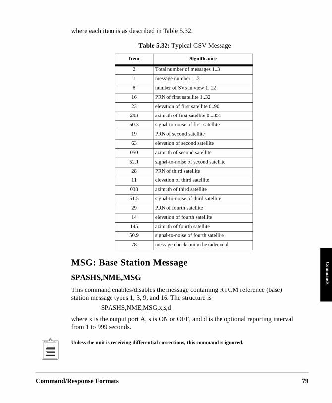
Command/
Com
mands
where each item is as described in Table 5.32.
MSG: Base Station Message
$PASHS,NME,MSG
This command enables/disables the message containing RTCM reference (base) station message types 1, 3, 9, and 16. The structure is
$PASHS,NME,MSG,x,s,d
where x is the output port A, s is ON or OFF, and d is the optional reporting interval from 1 to 999 seconds.
Unless the unit is receiving differential corrections, this command is ignored.
Table 5.32: Typical GSV Message
Item Significance
2 Total number of messages 1..3
1 message number 1..3
8 number of SVs in view 1..12
16 PRN of first satellite 1..32
23 elevation of first satellite 0..90
293 azimuth of first satellite 0...351
50.3 signal-to-noise of first satellite
19 PRN of second satellite
63 elevation of second satellite
050 azimuth of second satellite
52.1 signal-to-noise of second satellite
28 PRN of third satellite
11 elevation of third satellite
038 azimuth of third satellite
51.5 signal-to-noise of third satellite
29 PRN of fourth satellite
14 elevation of fourth satellite
145 azimuth of fourth satellite
50.9 signal-to-noise of fourth satellite
78 message checksum in hexadecimal
Response Formats 79
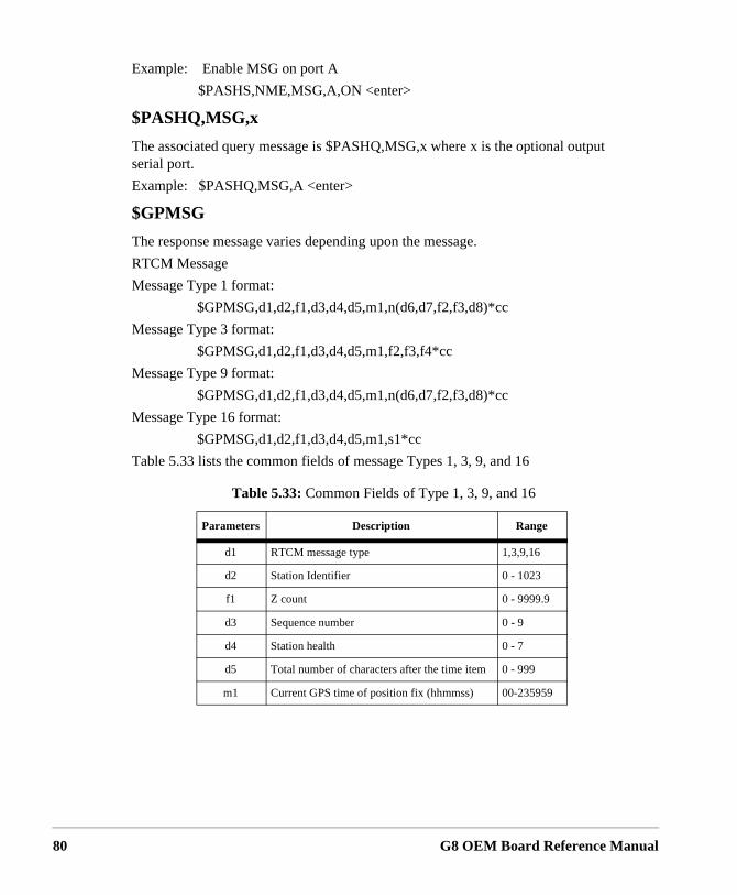
80
Example: Enable MSG on port A
$PASHS,NME,MSG,A,ON <enter>
$PASHQ,MSG,x
The associated query message is $PASHQ,MSG,x where x is the optional output serial port.
Example: $PASHQ,MSG,A <enter>
$GPMSG
The response message varies depending upon the message.
RTCM Message
Message Type 1 format:
$GPMSG,d1,d2,f1,d3,d4,d5,m1,n(d6,d7,f2,f3,d8)*cc
Message Type 3 format:
$GPMSG,d1,d2,f1,d3,d4,d5,m1,f2,f3,f4*cc
Message Type 9 format:
$GPMSG,d1,d2,f1,d3,d4,d5,m1,n(d6,d7,f2,f3,d8)*cc
Message Type 16 format:
$GPMSG,d1,d2,f1,d3,d4,d5,m1,s1*cc
Table 5.33 lists the common fields of message Types 1, 3, 9, and 16
Table 5.33: Common Fields of Type 1, 3, 9, and 16
Parameters Description Range
d1 RTCM message type 1,3,9,16
d2 Station Identifier 0 - 1023
f1 Z count 0 - 9999.9
d3 Sequence number 0 - 9
d4 Station health 0 - 7
d5 Total number of characters after the time item 0 - 999
m1 Current GPS time of position fix (hhmmss) 00-235959
G8 OEM Board Reference Manual
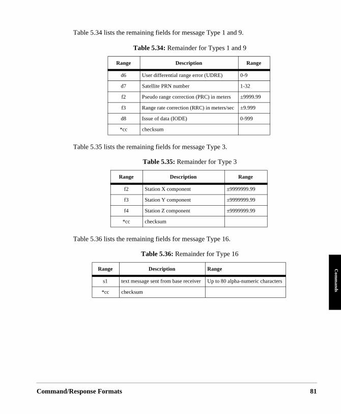
Command/
Com
mands
Table 5.34 lists the remaining fields for message Type 1 and 9.
Table 5.35 lists the remaining fields for message Type 3.
Table 5.36 lists the remaining fields for message Type 16.
Table 5.34: Remainder for Types 1 and 9
Range Description Range
d6 User differential range error (UDRE) 0-9
d7 Satellite PRN number 1-32
f2 Pseudo range correction (PRC) in meters ±9999.99
f3 Range rate correction (RRC) in meters/sec ±9.999
d8 Issue of data (IODE) 0-999
*cc checksum
Table 5.35: Remainder for Type 3
Range Description Range
f2 Station X component ±9999999.99
f3 Station Y component ±9999999.99
f4 Station Z component ±9999999.99
*cc checksum
Table 5.36: Remainder for Type 16
Range Description Range
s1 text message sent from base receiver Up to 80 alpha-numeric characters
*cc checksum
Response Formats 81
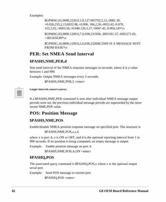
82
Examples:
$GPMSG,01,0000,2220.0,1,0,127,003702,2,12,-0081.30, +0.026,235,2,13,0022.86,+0.006, 106,2,26,-0053.42,-0.070, 155,2,02,+0003.56,+0.040,120,2,27,+0047.42,-0.004,145*cc
$GPMSG,03,0000,1200.0,7,0,038,231958,-2691561.37,-4301271.02, +3851650.89*cc
$GPMSG,16,0000,1209.6,5,0,036,232008,THIS IS A MESSAGE SENT FROM BASE*cc
PER: Set NMEA Send Interval
$PASHS,NME,PER,d
Sets send interval of the NMEA response messages in seconds, where d is a value between 1 and 999.
Example: Output NMEA messages every 5 seconds:
$PASHS,NME,PER,5 <enter>
Longer intervals conserve power.
If a $PASHS,NME,PER command is sent after individual NMEA message output periods were set, the previous individual message periods are superseded by the more recent NME,PER value.
POS: Position Message
$PASHS,NME,POS
Enable/disable NMEA position response message on specified port. The structure is
$PASHS,NME,POS,x,s,d
where x is port A, s is ON or OFF, and d is the optional reporting interval from 1 to 999 seconds. If no position is being computed, an empty message is output.
Example: Enable position message on port A
$PASHS,NME,POS,A,ON <enter>
$PASHQ,POS
The associated query command is $PASHQ,POS,x where x is the optional output serial port.
Example: Send POS message to current port
$PASHQ,POS <enter>
G8 OEM Board Reference Manual
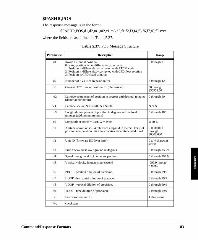
Command/
Com
mands
$PASHR,POSThe response message is in the form:
$PASHR,POS,d1,d2,m1,m2,c1,m3,c2,f1,f2,f3,f4,f5,f6,f7,f8,f9,s*cc
where the fields are as defined in Table 5.37.
Table 5.37: POS Message Structure
Parameters Description Range
d1 Raw/differential position 0: Raw; position is not differentially corrected1: Position is differentially corrected with RTCM code 2: Position is differentially corrected with CPD float solution3: Position is CPD fixed solution
0 through 3
d2 Number of SVs used in position fix 3 through 12
m1 Current UTC time of position fix (hhmmss.ss) 00 through 235959.50
m2 Latitude component of position in degrees and decimal minutes (ddmm.mmmmmm)
0 through 90
c1 Latitude sector, N = North, S = South N or S
m3 Longitude component of position in degrees and decimal minutes (dddmm.mmmmmm)
0 through 180
c2 Longitude sector E = East, W = West W or E
f1 Altitude above WGS-84 reference ellipsoid in meters. For 2-D position computation this item contains the altitude held fixed.
-30000.000 through 30000.000
f2 Unit ID (firmware HD00 or later) 0 to 4 character string
f3 True track/course over ground in degrees 0 through 359.9
f4 Speed over ground in kilometers per hour 0 through 999.9
f5 Vertical velocity in meters per second −999.9 through+ 999.9
f6 PDOP - position dilution of precision, 0 through 99.9
f7 HDOP - horizontal dilution of precision. 0 through 99.9
f8 VDOP - vertical dilution of precision. 0 through 99.9
f9 TDOP - time dilution of precision. 0 through 99.9
s Firmware version ID 4 char string
*cc checksum
Response Formats 83
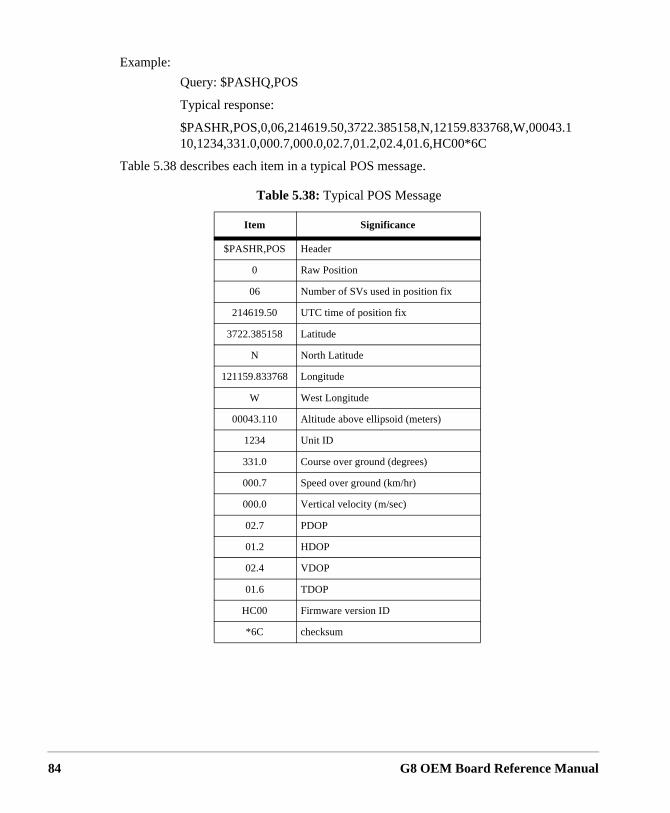
84
Example:
Query: $PASHQ,POS
Typical response:
$PASHR,POS,0,06,214619.50,3722.385158,N,12159.833768,W,00043.110,1234,331.0,000.7,000.0,02.7,01.2,02.4,01.6,HC00*6C
Table 5.38 describes each item in a typical POS message.
Table 5.38: Typical POS Message
Item Significance
$PASHR,POS Header
0 Raw Position
06 Number of SVs used in position fix
214619.50 UTC time of position fix
3722.385158 Latitude
N North Latitude
121159.833768 Longitude
W West Longitude
00043.110 Altitude above ellipsoid (meters)
1234 Unit ID
331.0 Course over ground (degrees)
000.7 Speed over ground (km/hr)
000.0 Vertical velocity (m/sec)
02.7 PDOP
01.2 HDOP
02.4 VDOP
01.6 TDOP
HC00 Firmware version ID
*6C checksum
G8 OEM Board Reference Manual
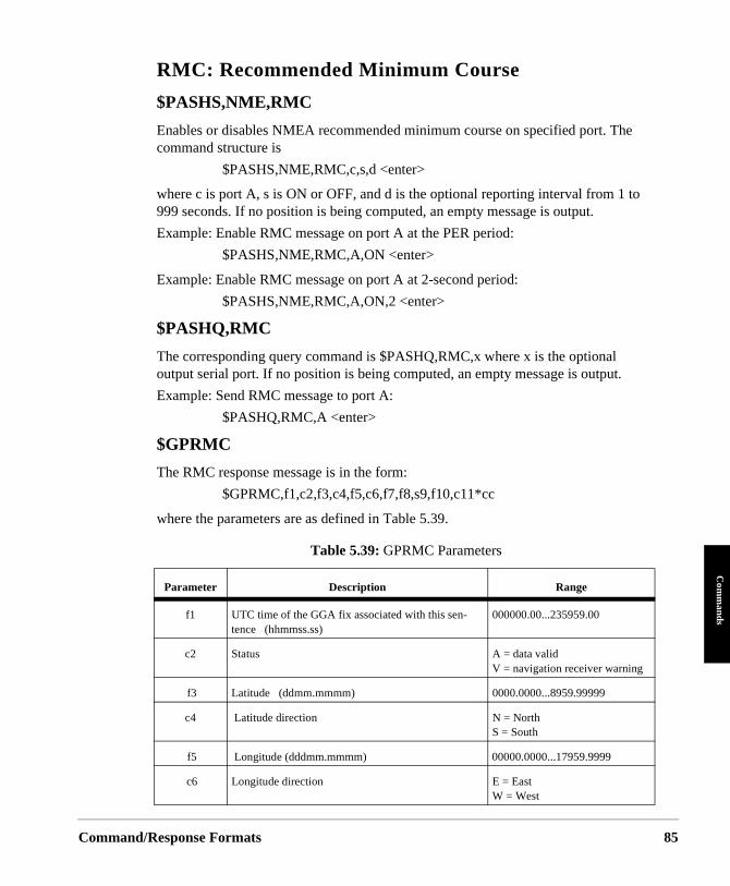
Command/
Com
mands
RMC: Recommended Minimum Course
$PASHS,NME,RMC
Enables or disables NMEA recommended minimum course on specified port. The command structure is
$PASHS,NME,RMC,c,s,d <enter>
where c is port A, s is ON or OFF, and d is the optional reporting interval from 1 to 999 seconds. If no position is being computed, an empty message is output.
Example: Enable RMC message on port A at the PER period:
$PASHS,NME,RMC,A,ON <enter>
Example: Enable RMC message on port A at 2-second period:
$PASHS,NME,RMC,A,ON,2 <enter>
$PASHQ,RMC
The corresponding query command is $PASHQ,RMC,x where x is the optional output serial port. If no position is being computed, an empty message is output.
Example: Send RMC message to port A:
$PASHQ,RMC,A <enter>
$GPRMC
The RMC response message is in the form:
$GPRMC,f1,c2,f3,c4,f5,c6,f7,f8,s9,f10,c11*cc
where the parameters are as defined in Table 5.39.
Table 5.39: GPRMC Parameters
Parameter Description Range
f1 UTC time of the GGA fix associated with this sen-tence (hhmmss.ss)
000000.00...235959.00
c2 Status A = data valid V = navigation receiver warning
f3 Latitude (ddmm.mmmm) 0000.0000...8959.99999
c4 Latitude direction N = North S = South
f5 Longitude (dddmm.mmmm) 00000.0000...17959.9999
c6 Longitude direction E = EastW = West
Response Formats 85
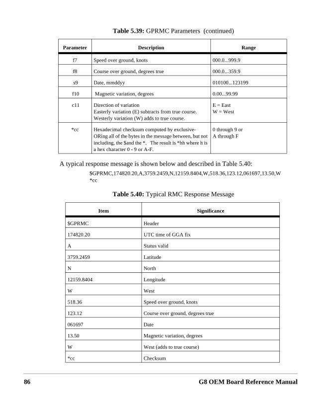
86
A typical response message is shown below and described in Table 5.40:
$GPRMC,174820.20,A,3759.2459,N,12159.8404,W,518.36,123.12,061697,13.50,W*cc
f7 Speed over ground, knots 000.0...999.9
f8 Course over ground, degrees true 000.0...359.9
s9 Date, mmddyy 010100...123199
f10 Magnetic variation, degrees 0.00...99.99
c11 Direction of variation Easterly variation (E) subtracts from true course.Westerly variation (W) adds to true course.
E = East W = West
*cc Hexadecimal checksum computed by exclusive-ORing all of the bytes in the message between, but not including, the $and the *. The result is *hh where h is a hex character 0 - 9 or A-F.
0 through 9 orA through F
Table 5.40: Typical RMC Response Message
Item Significance
$GPRMC Header
174820.20 UTC time of GGA fix
A Status valid
3759.2459 Latitude
N North
12159.8404 Longitude
W West
518.36 Speed over ground, knots
123.12 Course over ground, degrees true
061697 Date
13.50 Magnetic variation, degrees
W West (adds to true course)
*cc Checksum
Table 5.39: GPRMC Parameters (continued)
Parameter Description Range
G8 OEM Board Reference Manual
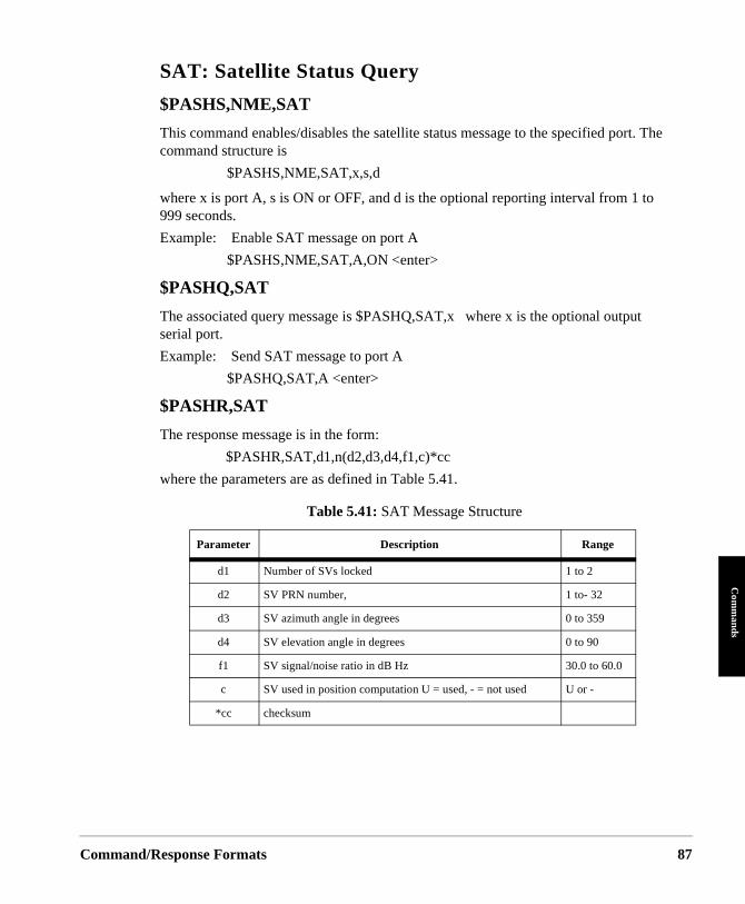
Command/
Com
mands
SAT: Satellite Status Query
$PASHS,NME,SAT
This command enables/disables the satellite status message to the specified port. The command structure is
$PASHS,NME,SAT,x,s,d
where x is port A, s is ON or OFF, and d is the optional reporting interval from 1 to 999 seconds.
Example: Enable SAT message on port A
$PASHS,NME,SAT,A,ON <enter>
$PASHQ,SAT
The associated query message is $PASHQ,SAT,x where x is the optional output serial port.
Example: Send SAT message to port A
$PASHQ,SAT,A <enter>
$PASHR,SAT
The response message is in the form:
$PASHR,SAT,d1,n(d2,d3,d4,f1,c)*cc
where the parameters are as defined in Table 5.41.
Table 5.41: SAT Message Structure
Parameter Description Range
d1 Number of SVs locked 1 to 2
d2 SV PRN number, 1 to- 32
d3 SV azimuth angle in degrees 0 to 359
d4 SV elevation angle in degrees 0 to 90
f1 SV signal/noise ratio in dB Hz 30.0 to 60.0
c SV used in position computation U = used, - = not used U or -
*cc checksum
Response Formats 87
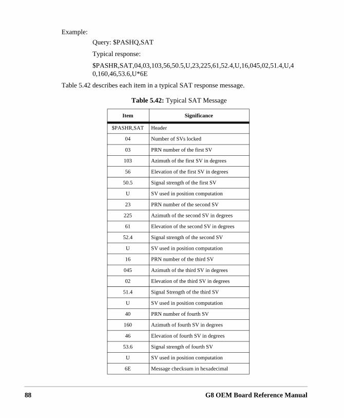
88
Example:
Query: $PASHQ,SAT
Typical response:
$PASHR,SAT,04,03,103,56,50.5,U,23,225,61,52.4,U,16,045,02,51.4,U,40,160,46,53.6,U*6E
Table 5.42 describes each item in a typical SAT response message.
Table 5.42: Typical SAT Message
Item Significance
$PASHR,SAT Header
04 Number of SVs locked
03 PRN number of the first SV
103 Azimuth of the first SV in degrees
56 Elevation of the first SV in degrees
50.5 Signal strength of the first SV
U SV used in position computation
23 PRN number of the second SV
225 Azimuth of the second SV in degrees
61 Elevation of the second SV in degrees
52.4 Signal strength of the second SV
U SV used in position computation
16 PRN number of the third SV
045 Azimuth of the third SV in degrees
02 Elevation of the third SV in degrees
51.4 Signal Strength of the third SV
U SV used in position computation
40 PRN number of fourth SV
160 Azimuth of fourth SV in degrees
46 Elevation of fourth SV in degrees
53.6 Signal strength of fourth SV
U SV used in position computation
6E Message checksum in hexadecimal
G8 OEM Board Reference Manual
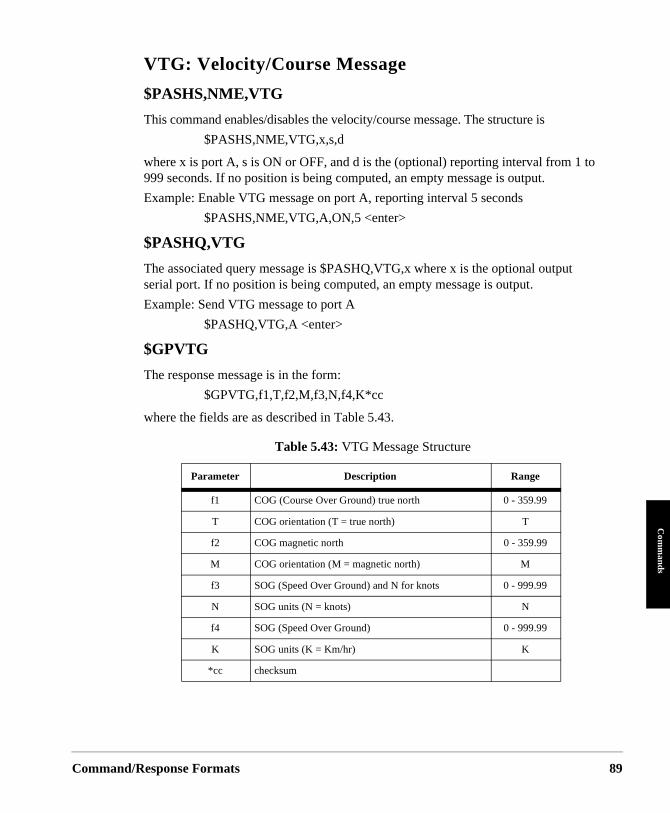
Command/
Com
mands
VTG: Velocity/Course Message
$PASHS,NME,VTG
This command enables/disables the velocity/course message. The structure is
$PASHS,NME,VTG,x,s,d
where x is port A, s is ON or OFF, and d is the (optional) reporting interval from 1 to 999 seconds. If no position is being computed, an empty message is output.
Example: Enable VTG message on port A, reporting interval 5 seconds
$PASHS,NME,VTG,A,ON,5 <enter>
$PASHQ,VTG
The associated query message is $PASHQ,VTG,x where x is the optional output serial port. If no position is being computed, an empty message is output.
Example: Send VTG message to port A
$PASHQ,VTG,A <enter>
$GPVTG
The response message is in the form:
$GPVTG,f1,T,f2,M,f3,N,f4,K*cc
where the fields are as described in Table 5.43.
Table 5.43: VTG Message Structure
Parameter Description Range
f1 COG (Course Over Ground) true north 0 - 359.99
T COG orientation (T = true north) T
f2 COG magnetic north 0 - 359.99
M COG orientation (M = magnetic north) M
f3 SOG (Speed Over Ground) and N for knots 0 - 999.99
N SOG units (N = knots) N
f4 SOG (Speed Over Ground) 0 - 999.99
K SOG units (K = Km/hr) K
*cc checksum
Response Formats 89
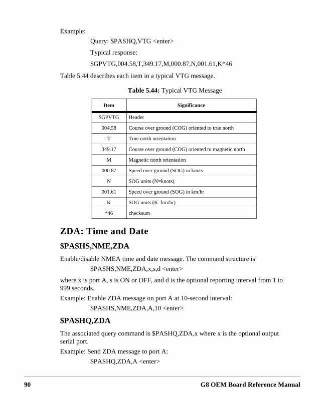
90
Example:
Query: $PASHQ,VTG <enter>
Typical response:
$GPVTG,004.58,T,349.17,M,000.87,N,001.61,K*46
Table 5.44 describes each item in a typical VTG message.
ZDA: Time and Date
$PASHS,NME,ZDA
Enable/disable NMEA time and date message. The command structure is
$PASHS,NME,ZDA,x,s,d <enter>
where x is port A, s is ON or OFF, and d is the optional reporting interval from 1 to 999 seconds.
Example: Enable ZDA message on port A at 10-second interval:
$PASHS,NME,ZDA,A,10 <enter>
$PASHQ,ZDA
The associated query command is $PASHQ,ZDA,x where x is the optional output serial port.
Example: Send ZDA message to port A:
$PASHQ,ZDA,A <enter>
Table 5.44: Typical VTG Message
Item Significance
$GPVTG Header
004.58 Course over ground (COG) oriented to true north
T True north orientation
349.17 Course over ground (COG) oriented to magnetic north
M Magnetic north orientation
000.87 Speed over ground (SOG) in knots
N SOG units (N=knots)
001.61 Speed over ground (SOG) in km/hr
K SOG units (K=km/hr)
*46 checksum
G8 OEM Board Reference Manual
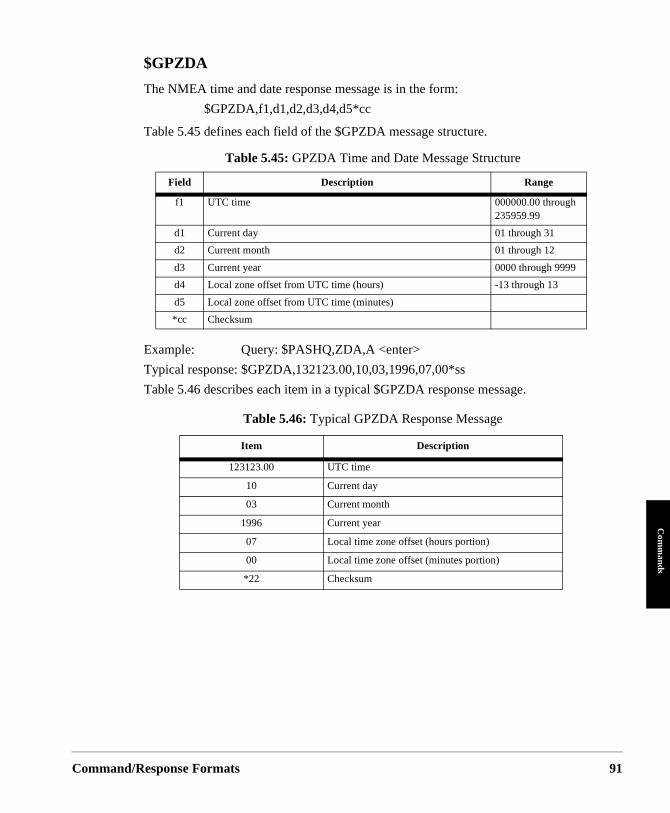
Command/
Com
mands
$GPZDA
The NMEA time and date response message is in the form:
$GPZDA,f1,d1,d2,d3,d4,d5*cc
Table 5.45 defines each field of the $GPZDA message structure.
Example: Query: $PASHQ,ZDA,A <enter>
Typical response: $GPZDA,132123.00,10,03,1996,07,00*ss
Table 5.46 describes each item in a typical $GPZDA response message.
Table 5.45: GPZDA Time and Date Message Structure
Field Description Range
f1 UTC time 000000.00 through 235959.99
d1 Current day 01 through 31
d2 Current month 01 through 12
d3 Current year 0000 through 9999
d4 Local zone offset from UTC time (hours) -13 through 13
d5 Local zone offset from UTC time (minutes)
*cc Checksum
Table 5.46: Typical GPZDA Response Message
Item Description
123123.00 UTC time
10 Current day
03 Current month
1996 Current year
07 Local time zone offset (hours portion)
00 Local time zone offset (minutes portion)
*22 Checksum
Response Formats 91
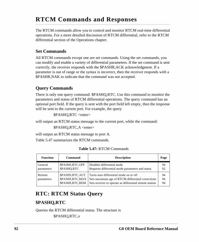
92
RTCM Commands and Responses
The RTCM commands allow you to control and monitor RTCM real-time differential operations. For a more detailed discussion of RTCM differential, refer to the RTCM differential section of the Operations chapter.
Set CommandsAll RTCM commands except one are set commands. Using the set commands, you can modify and enable a variety of differential parameters. If the set command is sent correctly, the receiver responds with the $PASHR,ACK acknowledgment. If a parameter is out of range or the syntax is incorrect, then the receiver responds with a $PASHR,NAK to indicate that the command was not accepted.
Query CommandsThere is only one query command: $PASHQ,RTC. Use this command to monitor the parameters and status of RTCM differential operations. The query command has an optional port field. If the query is sent with the port field left empty, then the response will be sent to the current port. For example, the query
$PASHQ,RTC <enter>
will output an RTCM status message to the current port, while the command:
$PASHQ,RTC,A <enter>
will output an RTCM status message to port A.
Table 5.47 summarizes the RTCM commands.
RTC: RTCM Status Query
$PASHQ,RTC
Queries the RTCM differential status. The structure is
$PASHQ,RTC,x
Table 5.47: RTCM Commands
Function Command Description Page
General parameters
$PASHS,RTC,OFF$PASHQ,RTC
Disables differential modeRequests differential mode parameters and status
9492
Remote parameters
$PASHS,RTC,AUT$PASHS,RTC,MAX$PASHS,RTC,REM
Turns auto differential mode on or offSets maximum age of RTCM differential correctionsSets receiver to operate as differential remote station
949494
G8 OEM Board Reference Manual

Command/
Com
mands
where x is the optional output port (A is the only valid value for port).
The return message is a free-form response format. A typical response message is shown below.
STATUS:
SYNC:* TYPE:00 STID:0000 STHE:0
AGE:±000 QA:100.00% OFFSET:00
SETUP:
MODE:OFF PORT:B AUT:N
MAX:0015
where the parameters are as defined in Table 5.48.
Table 5.48: RTC Parameters
Parameter Description Range
STATUS
SYNC Sync to last received RTCM message between receiver (remote) and base stations.
* = in sync
TYPE RTCM message type being received. 1, 3, 9, 16
STID Station ID received from the base station. 0...1023
STHE Station health received from the base station. 0...7
AGE Age of the received messages (seconds) 0...999
QA Communication quality factor between base and remote 0...100%
OFFSET Number of bits from the beginning of RTCM byte (in case of bit slippage)
SETUP
MODE RTCM mode REM, OFF
PORT Communication port A, B
AUT Automatic differential mode Y, N
CODE Code type used in differential C/A
MAX Maximum age, in seconds, required for a message to be used 0...3599
MSG Displays message up to 90 characters from base station
Response Formats 93
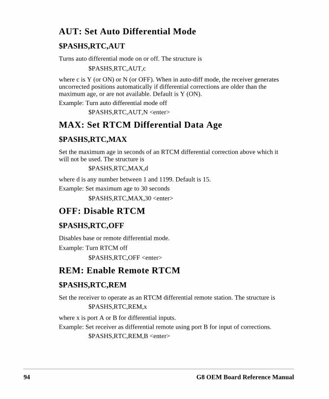
94
AUT: Set Auto Differential Mode
$PASHS,RTC,AUT
Turns auto differential mode on or off. The structure is
$PASHS,RTC,AUT,c
where c is Y (or ON) or N (or OFF). When in auto-diff mode, the receiver generates uncorrected positions automatically if differential corrections are older than the maximum age, or are not available. Default is Y (ON).
Example: Turn auto differential mode off
$PASHS,RTC,AUT,N <enter>
MAX: Set RTCM Differential Data Age
$PASHS,RTC,MAX
Set the maximum age in seconds of an RTCM differential correction above which it will not be used. The structure is
$PASHS,RTC,MAX,d
where d is any number between 1 and 1199. Default is 15.
Example: Set maximum age to 30 seconds
$PASHS,RTC,MAX,30 <enter>
OFF: Disable RTCM
$PASHS,RTC,OFF
Disables base or remote differential mode.
Example: Turn RTCM off
$PASHS,RTC,OFF <enter>
REM: Enable Remote RTCM
$PASHS,RTC,REM
Set the receiver to operate as an RTCM differential remote station. The structure is
$PASHS,RTC,REM,x
where x is port A or B for differential inputs.
Example: Set receiver as differential remote using port B for input of corrections.
$PASHS,RTC,REM,B <enter>
G8 OEM Board Reference Manual
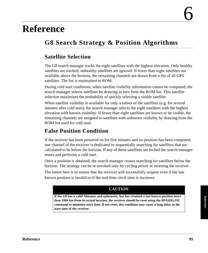
6
ReferenceReference
Reference
G8 Search Strategy & Position Algorithms
Satellite Selection
The G8 search manager tracks the eight satellites with the highest elevation. Only healthy satellites are tracked; unhealthy satellites are ignored. If fewer than eight satellites are available above the horizon, the remaining channels are drawn from a list of all GPS satellites. The list is maintained in ROM.
During cold start conditions, when satellite visibility information cannot be computed, the search manager selects satellites by drawing in turn from the ROM list. This satellite selection maximizes the probability of quickly selecting a visible satellite.
When satellite visibility is available for only a subset of the satellites (e.g. for several minutes after cold start), the search manager selects the eight satellites with the highest elevation with known visibility. If fewer than eight satellites are known to be visible, the remaining channels are assigned to satellites with unknown visibility by drawing from the ROM list used for cold start.
False Position Condition
If the receiver has been powered on for five minutes and no position has been computed, one channel of the receiver is dedicated to sequentially searching for satellites that are calculated to be below the horizon. If any of these satellites are locked the search manager resets and performs a cold start.
Once a position is obtained, the search manager ceases searching for satellites below the horizon. The strategy can be re-invoked only by cycling power or resetting the receiver.
The intent here is to ensure that the receiver will successfully acquire even if the last known position is invalid or if the real-time clock time is incorrect.
CAUTION
If the G8 has a valid Almanac and ephemeris, but has retained a last known position more than 1000 km from its actual location, the receiver should be reset using the $PASHS,INI command to minimize start time. If not reset, this condition may cause a long delay in the start time of the receiver.
95
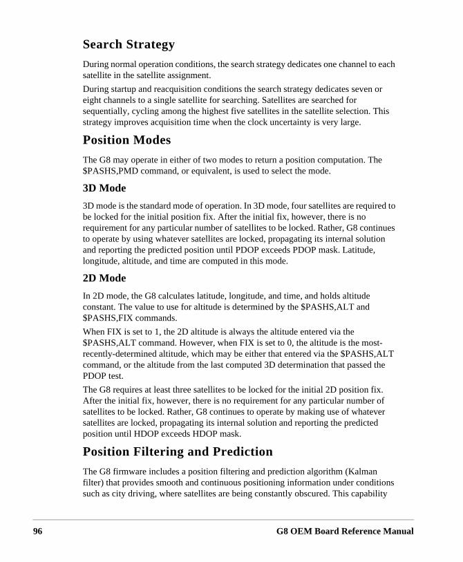
96
Search Strategy
During normal operation conditions, the search strategy dedicates one channel to each satellite in the satellite assignment.
During startup and reacquisition conditions the search strategy dedicates seven or eight channels to a single satellite for searching. Satellites are searched for sequentially, cycling among the highest five satellites in the satellite selection. This strategy improves acquisition time when the clock uncertainty is very large.
Position Modes
The G8 may operate in either of two modes to return a position computation. The $PASHS,PMD command, or equivalent, is used to select the mode.
3D Mode
3D mode is the standard mode of operation. In 3D mode, four satellites are required to be locked for the initial position fix. After the initial fix, however, there is no requirement for any particular number of satellites to be locked. Rather, G8 continues to operate by using whatever satellites are locked, propagating its internal solution and reporting the predicted position until PDOP exceeds PDOP mask. Latitude, longitude, altitude, and time are computed in this mode.
2D Mode
In 2D mode, the G8 calculates latitude, longitude, and time, and holds altitude constant. The value to use for altitude is determined by the $PASHS,ALT and $PASHS,FIX commands.
When FIX is set to 1, the 2D altitude is always the altitude entered via the $PASHS,ALT command. However, when FIX is set to 0, the altitude is the most-recently-determined altitude, which may be either that entered via the $PASHS,ALT command, or the altitude from the last computed 3D determination that passed the PDOP test.
The G8 requires at least three satellites to be locked for the initial 2D position fix. After the initial fix, however, there is no requirement for any particular number of satellites to be locked. Rather, G8 continues to operate by making use of whatever satellites are locked, propagating its internal solution and reporting the predicted position until HDOP exceeds HDOP mask.
Position Filtering and Prediction
The G8 firmware includes a position filtering and prediction algorithm (Kalman filter) that provides smooth and continuous positioning information under conditions such as city driving, where satellites are being constantly obscured. This capability
G8 OEM Board Reference Manual
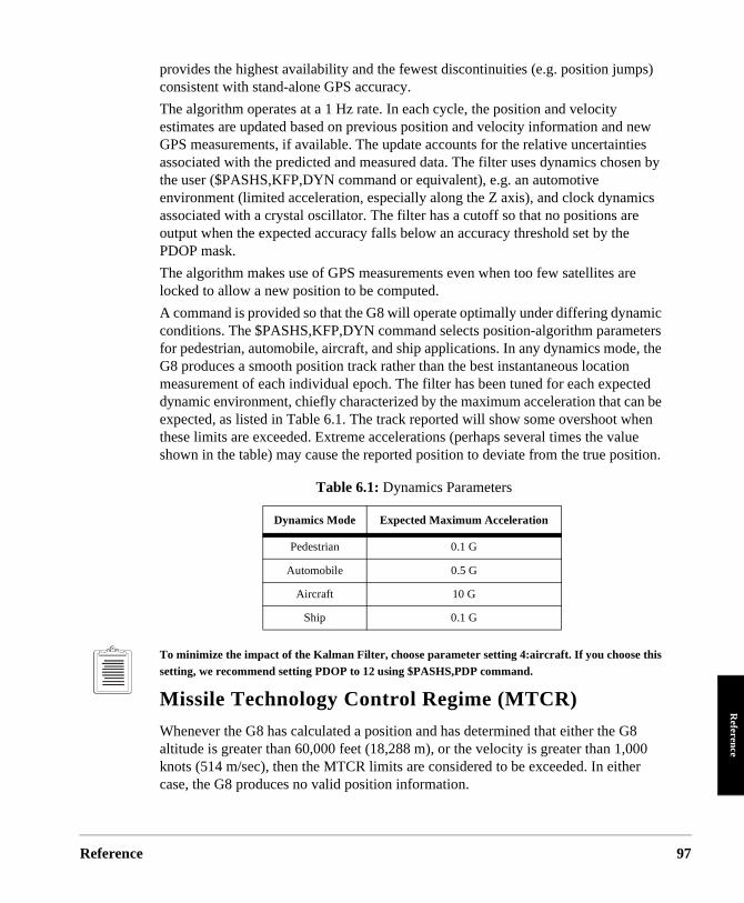
Reference
Reference
provides the highest availability and the fewest discontinuities (e.g. position jumps) consistent with stand-alone GPS accuracy.
The algorithm operates at a 1 Hz rate. In each cycle, the position and velocity estimates are updated based on previous position and velocity information and new GPS measurements, if available. The update accounts for the relative uncertainties associated with the predicted and measured data. The filter uses dynamics chosen by the user ($PASHS,KFP,DYN command or equivalent), e.g. an automotive environment (limited acceleration, especially along the Z axis), and clock dynamics associated with a crystal oscillator. The filter has a cutoff so that no positions are output when the expected accuracy falls below an accuracy threshold set by the PDOP mask.
The algorithm makes use of GPS measurements even when too few satellites are locked to allow a new position to be computed.
A command is provided so that the G8 will operate optimally under differing dynamic conditions. The $PASHS,KFP,DYN command selects position-algorithm parameters for pedestrian, automobile, aircraft, and ship applications. In any dynamics mode, the G8 produces a smooth position track rather than the best instantaneous location measurement of each individual epoch. The filter has been tuned for each expected dynamic environment, chiefly characterized by the maximum acceleration that can be expected, as listed in Table 6.1. The track reported will show some overshoot when these limits are exceeded. Extreme accelerations (perhaps several times the value shown in the table) may cause the reported position to deviate from the true position.
To minimize the impact of the Kalman Filter, choose parameter setting 4:aircraft. If you choose this setting, we recommend setting PDOP to 12 using $PASHS,PDP command.
Missile Technology Control Regime (MTCR)
Whenever the G8 has calculated a position and has determined that either the G8 altitude is greater than 60,000 feet (18,288 m), or the velocity is greater than 1,000 knots (514 m/sec), then the MTCR limits are considered to be exceeded. In either case, the G8 produces no valid position information.
Table 6.1: Dynamics Parameters
Dynamics Mode Expected Maximum Acceleration
Pedestrian 0.1 G
Automobile 0.5 G
Aircraft 10 G
Ship 0.1 G
97
98
peed se is
is
d d.
urs,
that . A
er is
will n for
Other G8 Operational Characteristics
Conversions
The G8 can perform the following conversions:
• Convert latitude and longitude rates to course over ground (COG) and sover ground (SOG). In case of speeds below 1 m/s, the last known courheld.
• Convert course over ground from true bearing to magnetic bearing. Thiscomputed from a table containing global magnetic variations.
• Convert altitude from height above WGS-84 ellipsoid to mean sea level,using a table containing a geoid undulation model
Self Test
Built In Test (BIT) algorithms determine the general health of the G8 memory anverify the integrity of information saved in backup RAM. Invalid data are not use
Watchdog Timer
The G8 utilizes a watchdog timer to enable it to recover from firmware errors. Innormal operation, the timer is regularly reset. If an irreversible firmware error occthe timer will expire and the receiver automatically restarts.
System Parameter Settings
The G8 can save all current parameter settings using a $PASHS command suchduring a power interruption these settings will be utilized when power is restored$PASHS command can also be used to revert to default settings.
Sleep Mode
The G8 can be set via software command to enter a sleep mode where less powconsumed. The sleep mode has the following characteristics:
• The $PASH,PWR command places the G8 in a sleep state. • Activity on the RS-232 port returns the G8 to the power-on state.
Long-Term Operation
The G8 is capable of long-term non-stop operation. None of the following eventsaffect operation or cause any change in performance during continuous operatio
G8 OEM Board Reference Manual
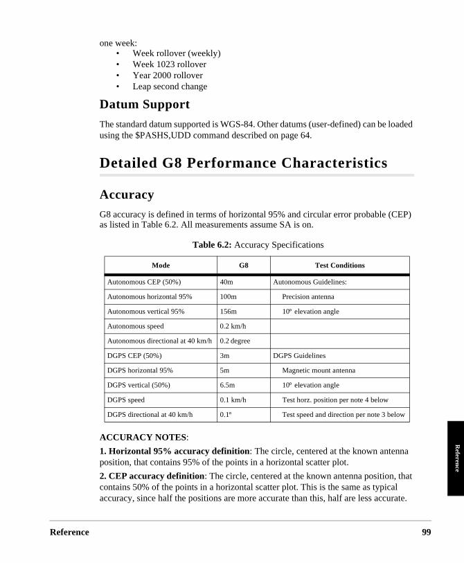
Reference
Reference
oaded
EP)
at l rate.
w
one week:• Week rollover (weekly)• Week 1023 rollover• Year 2000 rollover• Leap second change
Datum Support
The standard datum supported is WGS-84. Other datums (user-defined) can be lusing the $PASHS,UDD command described on page 64.
Detailed G8 Performance Characteristics
Accuracy
G8 accuracy is defined in terms of horizontal 95% and circular error probable (Cas listed in Table 6.2. All measurements assume SA is on.
ACCURACY NOTES:
1. Horizontal 95% accuracy definition: The circle, centered at the known antennaposition, that contains 95% of the points in a horizontal scatter plot.
2. CEP accuracy definition: The circle, centered at the known antenna position, thcontains 50% of the points in a horizontal scatter plot. This is the same as typicaaccuracy, since half the positions are more accurate than this, half are less accu
Table 6.2: Accuracy Specifications
Mode G8 Test Conditions
Autonomous CEP (50%) 40m Autonomous Guidelines:
Autonomous horizontal 95% 100m Precision antenna
Autonomous vertical 95% 156m 10° elevation angle
Autonomous speed 0.2 km/h
Autonomous directional at 40 km/h 0.2 degree
DGPS CEP (50%) 3m DGPS Guidelines
DGPS horizontal 95% 5m Magnetic mount antenna
DGPS vertical (50%) 6.5m 10° elevation angle
DGPS speed 0.1 km/h Test horz. position per note 4 below
DGPS directional at 40 km/h 0.1° Test speed and direction per note 3 belo
99
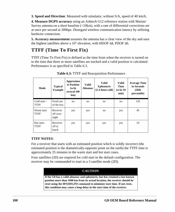
100
on ted.
is
3. Speed and Direction: Measured with simulator, without S/A, speed of 40 km/h.
4. Measure DGPS accuracy using an Ashtech G12 reference station with Marine/Survey antenna on a short baseline (<10km), with a rate of differential corrections set at once per second at 300bps. Disregard wireless communication latency by utilizing hardwire connection.
5. Accuracy measurement assumes the antenna has a clear view of the sky and uses the highest satellites above a 10° elevation, with HDOP ≤4, PDOP ≤6.
TTFF (Time To First Fix)
TTFF (Time To First Fix) is defined as the time from when the receiver is turnedto the time that three or more satellites are tracked and a valid position is calculaPerformance is as specified in Table 6.3.
TTFF NOTES:
For a receiver that starts with an estimated position which is wildly incorrect (theestimated position is the diametrically-opposite point on the earth) the TTFF timeapproximately 25 minutes in the warm start and hot start cases.
Four satellites (3D) are required for cold start in the default configuration. The receiver may be commanded to start in a 3 satellite mode (2D).
Table 6.3: TTFF and Reacquisition Performance
ModeTypical
Example
Approximate Position
(w/in several 100
km)
Valid Almanac
Valid Ephemeris
(2-4 hours old)
Valid Time
(w/in 10 min)
Average Time in Seconds
(50th percentile)
Cold start - TTFF
Fresh out of the box
no no no no 120
Warm start TTFF
Receiver off over-night
yes yes no yes 45
Hot start- TTFF
Receiver off at lunch
yes yes yes yes 10
CAUTION
If the G8 has a valid almanac and ephemeris, but has retained a last known position more than 1000 km from its actual location, the receiver should be reset using the $PASHS,INI command to minimize start time. If not reset, this condition may cause a long delay in the start time of the receiver.
G8 OEM Board Reference Manual
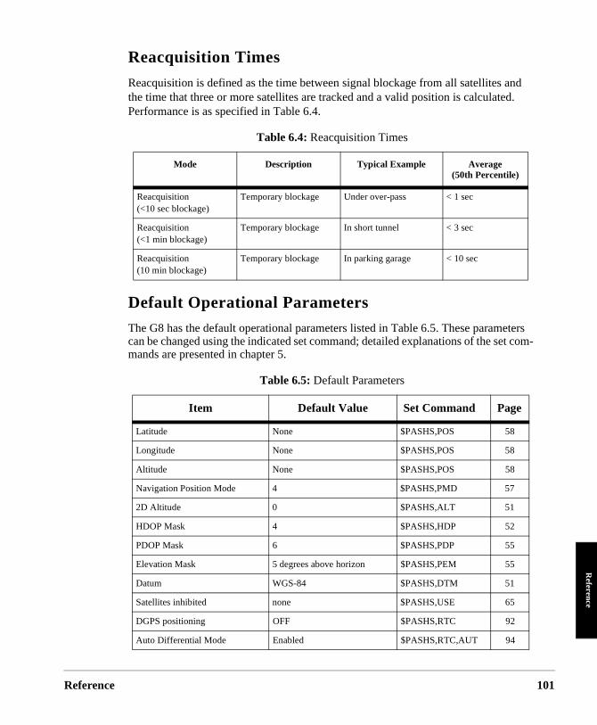
Reference
Reference
Reacquisition Times
Reacquisition is defined as the time between signal blockage from all satellites and the time that three or more satellites are tracked and a valid position is calculated. Performance is as specified in Table 6.4.
Default Operational Parameters
The G8 has the default operational parameters listed in Table 6.5. These parameters can be changed using the indicated set command; detailed explanations of the set com-mands are presented in chapter 5.
Table 6.4: Reacquisition Times
Mode Description Typical Example Average(50th Percentile)
Reacquisition(<10 sec blockage)
Temporary blockage Under over-pass < 1 sec
Reacquisition(<1 min blockage)
Temporary blockage In short tunnel < 3 sec
Reacquisition(10 min blockage)
Temporary blockage In parking garage < 10 sec
Table 6.5: Default Parameters
Item Default Value Set Command Page
Latitude None $PASHS,POS 58
Longitude None $PASHS,POS 58
Altitude None $PASHS,POS 58
Navigation Position Mode 4 $PASHS,PMD 57
2D Altitude 0 $PASHS,ALT 51
HDOP Mask 4 $PASHS,HDP 52
PDOP Mask 6 $PASHS,PDP 55
Elevation Mask 5 degrees above horizon $PASHS,PEM 55
Datum WGS-84 $PASHS,DTM 51
Satellites inhibited none $PASHS,USE 65
DGPS positioning OFF $PASHS,RTC 92
Auto Differential Mode Enabled $PASHS,RTC,AUT 94
101
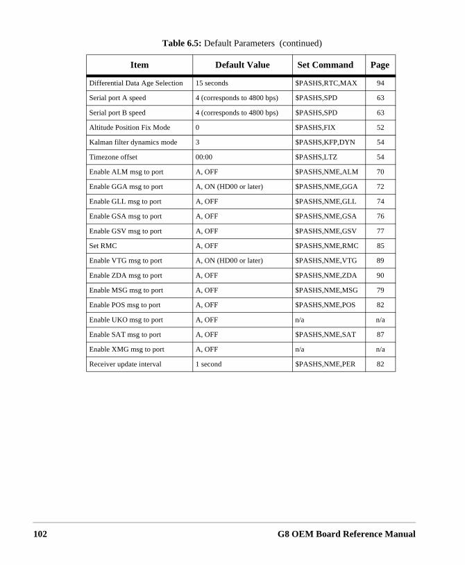
102
Differential Data Age Selection 15 seconds $PASHS,RTC,MAX 94
Serial port A speed 4 (corresponds to 4800 bps) $PASHS,SPD 63
Serial port B speed 4 (corresponds to 4800 bps) $PASHS,SPD 63
Altitude Position Fix Mode 0 $PASHS,FIX 52
Kalman filter dynamics mode 3 $PASHS,KFP,DYN 54
Timezone offset 00:00 $PASHS,LTZ 54
Enable ALM msg to port A, OFF $PASHS,NME,ALM 70
Enable GGA msg to port A, ON (HD00 or later) $PASHS,NME,GGA 72
Enable GLL msg to port A, OFF $PASHS,NME,GLL 74
Enable GSA msg to port A, OFF $PASHS,NME,GSA 76
Enable GSV msg to port A, OFF $PASHS,NME,GSV 77
Set RMC A, OFF $PASHS,NME,RMC 85
Enable VTG msg to port A, ON (HD00 or later) $PASHS,NME,VTG 89
Enable ZDA msg to port A, OFF $PASHS,NME,ZDA 90
Enable MSG msg to port A, OFF $PASHS,NME,MSG 79
Enable POS msg to port A, OFF $PASHS,NME,POS 82
Enable UKO msg to port A, OFF n/a n/a
Enable SAT msg to port A, OFF $PASHS,NME,SAT 87
Enable XMG msg to port A, OFF n/a n/a
Receiver update interval 1 second $PASHS,NME,PER 82
Table 6.5: Default Parameters (continued)
Item Default Value Set Command Page
G8 OEM Board Reference Manual
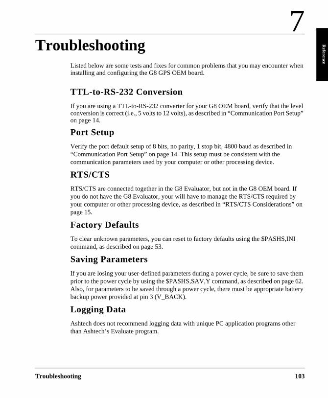
7
Referen
Troubleshooting
ce
Troublesho
tup”
. If by s” on
NI
them e 62. attery
er
Listed below are some tests and fixes for common problems that you may encounter when installing and configuring the G8 GPS OEM board.
TTL-to-RS-232 Conversion
If you are using a TTL-to-RS-232 converter for your G8 OEM board, verify that the level conversion is correct (i.e., 5 volts to 12 volts), as described in “Communication Port Seon page 14.
Port Setup
Verify the port default setup of 8 bits, no parity, 1 stop bit, 4800 baud as described in“Communication Port Setup” on page 14. This setup must be consistent with the communication parameters used by your computer or other processing device.
RTS/CTS
RTS/CTS are connected together in the G8 Evaluator, but not in the G8 OEM boardyou do not have the G8 Evaluator, your will have to manage the RTS/CTS required your computer or other processing device, as described in “RTS/CTS Considerationpage 15.
Factory Defaults
To clear unknown parameters, you can reset to factory defaults using the $PASHS,Icommand, as described on page 53.
Saving Parameters
If you are losing your user-defined parameters during a power cycle, be sure to saveprior to the power cycle by using the $PASHS,SAV,Y command, as described on pagAlso, for parameters to be saved through a power cycle, there must be appropriate bbackup power provided at pin 3 (V_BACK).
Logging Data
Ashtech does not recommend logging data with unique PC application programs oththan Ashtech’s Evaluate program.
oting 103

104
G8 OEM Board Reference Manual
Glossa
Glossary
ry
ed
r
n
rs, ta
y
d
Aerotriangulation (phototriangulation)A complex process vital to aerial Photogrammetry that involves extending vertical and/or horizontal control so that the measurements of angles and/or distances on overlapping photographs are related to a spatial solution using the perspective principles of the photographs. Aerotriangulation consists of mathematically extending the vectors/angles of the triangular pattern of known reference points on or near the designated photo-block terrain upward through a rectangle representing the area of the photo-block (as seen by the cameraoptical center) in such a way that the tree-pointerrain triangle and the camera’s eye three-poitriangle (within the photographic frame) are analogous.
AFTAfter
AGEAge of Data
ALMSee Almanac
AlmanacA set of parameters used by a GPS receiver predict the approximate locations of all GPS satellites and the expected satellite clock offsets. Each GPS satellite contains and transmits the almanac data for all GPS satellit(See Ellipsoid).
ALTAltitude
AmbiguityThe initial bias in a carrier-phase observation o
Glossary
’s t
nt
to
es
f
an arbitrary number of carrier cycles; the uncertainty of the number of carrier cycles a receiver is attempting to count. If wavelength isknown, the distance to a satellite can be computonce the number of cycles is established via carrier-phase processing.
AMIATM Management Interface
ANTAntenna
AntennaA variety of GPS antennas ranging from simplemicrostrip devices to complex choke ring antennas that mitigate the effects of multipath scattering.
Anti-Spoofing (AS)The process of encrypting the P-Code modulatiosequence so the code cannot be replicated by hostile forces. When encrypted, the P-Code is referred to as the Y-Code.
ASCIIAmerican Standard Code for Information Interchange. A set of characters (letters, numbesymbols) used to display and transfer digital dain human-readable format.
Atomic clockA clock whose frequency is maintained using electromagnetic waves that are emitted or absorbed in the transition of atomic particles between energy states. The frequency of an atomic transition is very precise, resulting in verstable clocks. A cesium clock has an error of about one second in one million years. For redundancy purposes, GPS satellites carry multiple atomic clocks. GPS satellites have use
Gloassary-1
ls
S to
es al
he k
of
n,
ne
rubidium clocks as well as cesium clocks. The GPS Master Control Station uses cesium clocks and a hydrogen master clock.
Argument of latitudeThe sum of the true anomaly and the argument of perigee.
Argument of perigeeThe angle or arc from the ascending node to the closest approach of the orbiting body to the focus or perigee, as measured at the focus of an elliptical orbit, in the orbital plane in the direction of motion of the orbiting body.
Ascending nodeThe point at which an object’s orbit crosses threference plane (e.g., equatorial plane) from south to north.
AZMSee AZM
BandwidthA measure of the information-carrying capacitof a signal expressed as the width of the spectrum of that signal (frequency domain representation) in Hertz.
BaselineThe measured distance between two receiveor two antennas
BiasSee Integer bias terms
BINBinary Index (file)
C/ACoarse Acquisition
C/A codeA sequence of 1023 bits (0 or 1) that repeats every millisecond. Each satellite broadcasts aunique 1023-bit sequence that allows a receivto distinguish between various satellites. The
Glossary-2
e
y
rs
er C/
A-Code modulates only the L1 carrier frequencyon GPS satellites. GPS satellite navigation signaare broadcast on two L-band frequencies, L1 is1575.42 MHz, and L2 is 1227.6 MHz.
Carrier phaseThe phase of either the L1 or L2 carrier of a GPsignal, measured by a receiver while locked-on the signal (also known as integrated Doppler).
CEPCircular error probable. That vertical circle through the elevated celestial pole, It also passthrough the other celestial pole, the astronomiczenith, and the nadir..
ChannelRefers to the hardware in a receiver that allows treceiver to detect, lock-on and continuously tracthe signal from a single satellite. The more receiver channels available, the greater numbersatellite signals a receiver can simultaneously lock-on and track.
ChipThe length of time to transmit either a zero or aone in a binary pulse code..
Chip rateNumber of chips per second (e.g., C/A code = 1.023 MHz).
Circular Error ProbableThe radius of a circle, centered at the true locatiowithin which 50% of position solutions fall. CEPis used for horizontal accuracy..
Clock offsetThe difference in time between GPS time and asatellite clock or a sensor clock (less accurate).radios use the same frequency both with each ohaving a separate and unique code. GPS uses CDMA techniques with Gold’s code from their unique cross-correlation properties.
G8 OEM Board Reference Manual
Glossary
COGCourse Over Ground
ConstellationRefers to the collection of orbiting GPS satellites. The GPS constellation consists of 24 satellites in 12-hour circular orbits at an altitude of 20,200 kilometers. In the nominal constellation, four satellites are spaced in each of six orbital planes. The constellation was selected to provoke a very high probability of satellite coverage even in the event of satellite outages..
CTDCourse To Destination
Cycle slipA loss of count of carrier cycles as they are being measured by a GPS receiver. Loss of signal, ionospheric interference and other forms of interference cause cycle slips to occur.
DGPSDifferential Global Positioning System
Differential GPS (DGPS)A technique whereby data from a receiver at a known location is used to correct the data from a receiver at an unknown location. Differential corrections can be applied in real-time or by post-processing. Since most of the errors in GPS are common to users in a wide area, the DGPS-corrected solution is significantly more accurate than a normal SPS solution.
Differential processingGPS measurements can be differenced between receivers, satellites, and epochs. Although many combinations are possible, the present convention for differential processing of GPS measurements is to take differences between receivers (single difference), then between satellites (double difference), then between measurement epochs (triple difference). A
Glossary
single-difference measurement between receivers is the instantaneous difference in phase of the signal from the same satellite, measured by two receivers simultaneously. A double-difference measurement is the difference for a chosen reference satellite. A triple-difference measurement is the difference between a double difference at one epoch and the same double difference at the previous epoch.
Differential (relative) positioningDetermination of relative coordinates of two or more receivers which are simultaneously tracking the same satellites. Dynamic differential positioning is a real-time calibration technique achieved by sending corrections to the roving user from one or more reference stations. Static differential GPS involves determining baseline vectors between pairs of receivers.
Dilution of Precision (DOP)A measure of the receiver-satellite(s) geometry. DOP relates the statistical accuracy of the GPS measurements to the statistical accuracy of the solution. Geometric Dilution of Precision (GDOP) is composed of Time Dilution of Precision (TDOP); and Position Dilution of Precision (PDOP), which are composed of Horizontal Dilution of Precision (HDOP); and Vertical Dilution of Precision (VDOP).
DOPDilution of Precision
Doppler aidingThe use of Doppler carrier-phase measurements to smooth code-phase position measurements.
Doppler shiftAn apparent change in signal frequency which occurs as the transmitter and receiver move toward or away from one another.
Double differenceThe arithmetic differencing of carrier phases
Glossary-3
measured simultaneously by a pair of receivers tracking the same pair of satellites. Single differences are obtained by each receiver from each satellite; these differences are then differenced in turn, which essentially deletes all satellite and receiver clock errors.
DTDDistance to Destination
Dynamic positioningDetermination of a timed series of sets of coordinates for a moving receiver, each set of coordinates being determined from a single data sample, and usually computed in real-time.
Earth Centered, Earth Fixed (ECEF)A cartesian coordinate system centered at the earth’s center of mass. The Z-axis is aligned with the earth’s mean spin axis. The X-axis is aligned with the zero meridian. The Y-axis is 90 degrees west of the X-axis, forming a right-handed coordinate system.ellipse to its focus to the semimajor axis.e = (1 - b2/a2)-1/2 where a and b are the semimajor and semiminor axes of the ellipse.
EDOPElevation Dilution of Precision
ELEVElevation
ElevationHeight above mean sea level. Vertical distance above the geoid.
Elevation maskAn adjustable feature of GPS receivers that specifies that a satellite must be at least a specified number of degrees above the horizon before the signals from the satellite are to be used. Satellites at low elevation angles (five degrees or less) have lower signal strengths and are more prone to loss of lock thus causing noisy solutions.
Glossary-4
Elevation mask angleThat angle below which it is not advisable to track satellites. Normally set to 15 degrees to avoid interference problems caused by buildings and trees and multipath reflections.
EllipsoidIn geodesy, unless otherwise specified, a mathematical figure formed by revolving an ellipse about its minor axis. It is often used interchangeably with spheroid. Two quantities define an ellipsoid; the length of the semimajor axis, a, and the flattening, f =- (a - b)/a, where b is the length of the semiminor axis. Prolate and triaxial ellipsoids are invariably described as such.
Ellipsoid heightThe measure of vertical distance above the ellipsoid. Not the same as elevation above sea level. GPS receiver output position fix height in the WGS-84 datum.
EphemerisA set of parameters used by a GPS receiver to predict the location of a single GPS satellite and its clock behavior. Each GPS satellite contains and transmits ephemeris data for its own orbit and clock. Ephemeris data is more accurate than the almanac data but is applicable over a short time frame (four to six hours). Ephemeris data is transmitted by the satellite every 30 seconds.
EpochMeasurement interval or data frequency, as in making observations every 15 seconds. Loading data using 30-second epochs means loading every other measurement.
FCCFederal Communications Commission
FirmwareThe coded instructions relating to receiver function, and (sometimes) data processing
G8 OEM Board Reference Manual
Glossary
algorithms, embedded as integral portions of the internal circuitry.
Flattening f = (a- b)/a = 1 - (1 - e2) 1/2 wherea = semimajor axisb = semiminor axise = Eccentricity
GDOPGeometric Dilution of Precision. The relationship between errors in user position and time and in satellite range. GDOP2 = PDOP2 + TDOP2. See Position Dilution of Precision..
Geodetic datum (horizontal datum)A specifically oriented ellipsoid typically defined by eight parameters which establish its dimensions, define its center with respect to Earth’s center of mass and specify its orientation in relation to the Earth’s average spin axis and Greenwich reference meridian.
Geodetic height (ellipsoidal height)The height of a point above an ellipsoidal surface. The difference between a point’s geodetic height and its orthometric height equals the geoidal height.
GeoidThe equipotential surface of the Earth’s gravity field which best fits mean sea level. Geoids currently in use are GEOID84 and GEOID90.
Geoidal height (geoidal separation; undulation)
The height of a point on the geoid above the ellipsoid measured along a perpendicular to the ellipsoid.
GLLPosition Latitude/Longitude
GMSTGreenwich Mean Sidereal Time
Glossary
GPS DIFFDifferential
GPS ICD-200The GPS Interface Control Document is a government document that contains the full technical description of the interface between the satellites and the user. GPS receiver must comply with this specification if it is to receive and process GPS signals properly.
GPS weekGPS time started at Saturday/Sunday midnight, January 6, 1980. The GPS week is the number of whole weeks since GPS time zero.
Greenwich mean time (GMT)See universal time. In this text, they are often used interchangeably.
HDOPHorizontal Dilution of Precision. See Dilution of Precision.
HIHeight of Instrument
HTDOPHorizontal/Time Dilution of Precision. See Dilution of Precision.
ID Identification or Integrated Doppler
Integer bias termsThe receiver counts the carrier waves from the satellite, as they pass the antenna, to a high degree of accuracy. However, it has no information of the number of waves to the satellite at the time it started counting. This unknown number of wavelengths between the satellite and the antenna is the integer bias term.
Integrated DopplerA measurement of Doppler shift frequency or phase over time.
Glossary-5
IonosphereRefers to the layers of ionized air in the atmosphere extending from 70 kilometers to 700 kilometers and higher. Depending on frequency, the ionosphere can either block radio signals completely or change the propagation speed. GPS signals penetrate the ionosphere but are delayed. The ionospheric delays can be predicted using models, though with relatively poor accuracy, or measured using two receivers.
Ionospheric delay A wave propagating through the ionosphere [which is a nonhomogeneous (in space and time) and dispersive medium] experiences delay. Phase delay depends on electron content and affects carrier signals. Group delay depends on dispersion in the ionosphere as well, and affects signal modulation (codes). The phase and group delay are of the same magnitude but opposite sign.
Julian dateThe number of days that have elapsed since 1 January 4713 B.C. in the Julian calendar. GPS time zero is defined to be midnight UTC, Saturday/Sunday, 6 January 1980 at Greenwich. The Julian date for GPS time zero is 2,444,244.5.
Kalman filterA numerical method used to track a time-varying signal in the presence of noise. If the signal can be characterized by some number of parameters that vary slowly with time, then Kalman filtering can be used to tell how incoming raw measurements should be processed to best estimate those parameters as a function of time.
Kinematic surveyingA method which initially solves wavelength ambiguities and retains the resulting
Glossary-6
measurements by maintaining a lock on a specific number of satellites throughout the entire surveying period.
L1The primary L-band signal radiated by each NAVSTAR satellite at 1575.42 MHz. The Ll beacon is modulated with the C/A and P codes, and with the NAV message. L2 is centered at 1227.60 MHz and is modulated with the P code and the NAV message.
L1 & L2 Designations of the two basic carrier frequencies transmitted by GPS satellites that contain the navigation signals. L1 is 1,575.42 MHz and L2 is 1,227.60 MHz.
LaneThe area (or volume) enclosed by adjacent lines (or surfaces) of zero phase of either the carrier beat phase signal or of the difference between two carrier beat phase signals. On the earth’s surface a line of zero phase is the focus of all points for which the observed value has an exact integer value for the complete instantaneous phase measurement. In three dimensions, this locus becomes a surface.
L-bandA nominal portion of the microwave electro-magnetic spectrum ranging from 390 MHz to 1.55 GHz.
LNALow-Noise Amplifier
MSGRTCM Message
MSLMean Sea Level
Multichannel receiverA receiver containing many independent channels. Such a receiver offers highest SNR
G8 OEM Board Reference Manual
Glossary
because each channel tracks one satellite continuously.
MultipathThe reception of a signal both along a direct path and along one or more reflected paths. The resulting signal results in an incorrect pseudorange measurement. The classical example of multipath is the "ghosting" that appears on television when an airplane passes overhead.
Multipath error A positioning error resulting from interference between radio waves which have traveled between the transmitter and the receiver by two paths of different electrical lengths.
MultiplexingA technique used in some GPS receivers to sequence the signals of two or more satellites through a single hardware channel. Multiplexing allows a receiver to track more satellites than the number of hardware channels at the cost of lower effective signal strength.
Multiplexing channelA receiver channel which is sequenced through several satellite signals (each from a specific satellite at a specific frequency) at a rate which is synchronous with the satellite message bit-rate (50 bits per second, or 20 milliseconds per bit). Thus, one complete sequence is completed in a multiple of 20 milliseconds.
NMEANational Marine Electronics Association
NVNon-Volatile. Usually refers to a memory device that retains data after power is removed.
OutageThe occurrence in time and space of a GPS dilution of precision value exceeding a specified maximum.
Glossary
P-CodePrecise or protected code which is bi-phase shift modulated on both the L1 and L2 carrier frequencies. P-code has a 10.23MHz bit rate and, as implemented in GPS, a period of 267 days. Each satellite has a unique one-week P-code segment that is used to distinguish the satellite from all other GPS satellites.
Position Dilution of Precision (PDOP)A unitless figure of merit expressing the relationship between the error in user position and the error in satellite position. Geometrically, POP is proportional to 1 divided by the volume of the pyramid formed by lines running from the receiver to four satellites observed. Values considered ’good’ for positioning are small, say 3. Values greater than 7 are considered poor. Thus, small PDOP is associated with widely separated satellites. PDOP is related to horizontal and vertical DOP by PDOP2 = HDOP2 + VDOP2. Small PDOP is important in positioning, but much less so in surveying.
PhotogrammetryAn aerial remote sensing technique whose latest innovations employ a high-resolution aerial camera with forward motion compensation and uses GPS technology for pilot guidance over the designated photo block(s). Photogrammetry forms the baseline of many Geographic Information Systems (GIS) and Land Information System (LIS) studies .
Point positioning A geographic position produced from one receiver in a stand-alone mode. At best, position accuracy obtained from a stand-alone receiver is 15-25 meters, depending on the geometry of the satellites.
POSPosition
Glossary-7
Post-processing The reduction and processing of GPS data after the data was collected in the field. Post-processing is usually accomplished on a computer in an office environment where appropriate software is employed to achieve optimum position solutions.
Precise Positioning System (PPS)The more accurate GPS capability that is restricted to authorized, typically military, users.
Pseudo-kinematic surveyingA variation of the kinematic method where roughly five-minute site occupations are repeated at a minimum of once each hour.
Pseudorandom noise (PRN)The P(Y) and C/A codes are pseudo-random noise sequences which modulate the navigation signals. The modulation appears to be random noise but is, in fact, predictable hence the term "pseudo" random. Use of this technique allows the use of a single frequency by all GPS satellites and also permits the satellites to broadcast a low power signal.
PseudorangeThe measured distance between the GPS receiver antenna and the GPS satellite. The pseudorange is approximately the geometric range biased by the offset of the receiver clock from the satellite clock. The receiver actually measures a time difference which is related to distance (range) by the speed of propagation.
PZ-90The proper designators for the GLONASS reference system. Sometimes referred to as E-90 or PE-90.
RAMRandom-Access Memory. A memory device whose data can be accessed at random, as
Glossary-8
approved to sequential access. RAM data is lost when power is removal.
Range rateThe rate of change of range between the satellite and receiver. The range to a satellite changes due to satellite and observer motions. Range rate is determined by measuring the doppler shift of the satellite beacon carrier.
RDOPRelative Dilution of Precision. See Dilution of Precision.
Reconstructed carrier phase1. The difference between the phase of the incoming Doppler-shifted GPS carrier and the phase of a nominally constant reference frequency generated in the receiver. For static positioning, the reconstructed carrier phase is sampled at epochs determined by a clock in the receiver. The reconstructed carrier phase changes according to the continuously integrated Doppler shift of the incoming signal biased by the integral of the frequency offset between the satellite and receiver reference oscillators.- or -2. The reconstructed carrier phase can be related to the satellite-to-receiver range, once the initial range (or phase ambiguity) has been determined. A change in the satellite-to-receiver range of one wavelength of the GPS carrier (19 cm for L1) will result in a one-cycle change in the phase of the reconstructed carrier.
Real-timeRefers to immediate, GPS data collection, processing and position determination (usually) within a receiver’s firmware after the fact with a computer in an office environment.
Real-time kinematic (RTK)A DGPS process where carrier-phase corrections are transmitted in real-time from a reference receiver at a known location to one or more
G8 OEM Board Reference Manual
Glossary
remote rover receiver(s).
Real-Time ZAshtech’s proprietary technique that includes Carrier Phase Differential (CPD) processing. Real-Time Z features "on-the-fly" (OTF) ranging data acquisition and differential processing.
Reference NetworkA series of monuments or reference points with accurately measured vectors/distances that is used as a reference basis for cadastral and other types of survey.
Reference stationA point (site) where crustal stability, or tidal current constants, have been determined through accurate observations, and which is then used as a standard for the comparison of simultaneous observations at one or more subordinate stations. Certain of these are known as Continuous Operating Reference Stations (CORS), and transmit reference data on a 24-hour basis.
Relative positioningThe process of determining the relative difference in position between two points with greater precision than that to which the position of a single point can be determined. Here, a receiver (antenna) is placed over each point and measurements are made by observing the same satellite at the same time. This technique allows cancellation (during computations) of all errors which are common to both observers, such as satellite clock errors, propagation delays, etc. See also Translocation and Differential Navigation.
RFRadio Frequency
RFIRadio Frequency Interference
Glossary
RINEXThe Receiver-INdependent EXchange format for GPS data, which includes provisions for pseudorange, carrier-phase, and Doppler observations.
RMSRoot Mean Square. A statistical measure of the scatter of computed positions about a "best fit" position solution. RMS can be applied to any random variable.
RTCMRadio Technical Commission for Maritime ServicesP.O. Box 19087Washington, DC. 20036-9087
RTCM SC-104 FormatA standard format used in the transmission of differential corrections.
SESite Editor or Standard Error
Selective Availability (SA)The process whereby DOD dithers the satellite clock and/or broadcasts erroneous orbital ephemeris data to create a pseudorange error
Spherical Error Probable (SEP)A statistical measure of precision defined as the 50th percentile value of the three-dimensional position error statistics. Thus, half of the results are within a 3D SEP value.
Sidereal day Time between two successive upper transits of the vernal equinox.
Sidereal timeThe hour angle of the vernal equinox. Taking the mean equinox as the reference yields true or apparent Sidereal Time. Neither Solar nor Sidereal Time are constant, since angular velocity varies due to fluctuations caused by the Earth’s
Glossary-9
polar moment of inertia as exerted through tidal deformation and other mass transports.
Single differenceThe arithmetic differencing of carrier phases simultaneously measured by a pair of receivers tracking the same satellite (between receivers and satellite), or by a single receiver tracking two satellites (between-satellite and receivers); the former essentially deletes all satellite clock errors, while the latter essentially deletes all receiver errors.
Spherical Error Probable (SEP)A navigational measure of accuracy equaling the radius of a sphere, centered on the true location, inside which 50% of the computed solutions lie.
SpoofingThe process of replicating the GPS code in such a way that the user computes incorrect position solutions.
Standard Positioning Service (SPS)Uses the C/A code to provide a minimum level of dynamic- or static-positioning capability. The accuracy of this service is set at a level consistent with national security.
Standard Positioning SystemThe less accurate GPS capability which is available to all.
Static observationsA GPS survey technique requiring roughly one hour of observation, with two or more receivers observing simultaneously, and results in high accuracies and vector measurements.
Static positioningPositioning applications in which the positions of static or near static points are determined.
SVSatellite Vehicle, Satellite Visibility or Space
Glossary-10
Vehicle.
Switching channelA receiver channel which is sequenced through a number of satellite signals (each from a specific satellite and at a specific frequency) at a rate which is slower than, and asynchronous with, the message data rate.
TDOPTime Dilution of Precision. See Dilution of Precision.
TOWTime of week, in seconds, from midnight Sunday UTC.
TranslocationA version of relative positioning which makes use of a known position, such as a USGS survey mark, to aid in the accurate positioning of a desired point. Here, the position of the mark, determined using GPS, is compared with the accepted value. The three-dimensional differences are then used in the calculations for the second point.
Triple differenceThe arithmetic difference of sequential, double-differenced carrier-phase observations that are free of integer ambiguities, and therefore useful for determining initial, approximate coordinates of a site in relative GPS positioning, and for detecting cycle slips in carrier-phase data.
Tropospheric correction. The correction applied to the measurement to account for tropospheric delay. This value is obtained from the modified Hopfield model.
True anomaly The angular distance, measured in the orbital plane from the earth’s center (occupied focus) from the perigee to the current location of the satellite (orbital body).
G8 OEM Board Reference Manual
Glossary
Universal Time Coordinated (UTC)Time as maintained by the U.S. Naval Observatory. Because of variations in the Earth’s rotation, UTC is sometimes adjusted by an integer second. The accumulation of these adjustments compared to GPS time, which runs continuously, has resulted in an 11 second offset between GPS time and UTC at the start of 1996. After accounting for leap seconds and using adjustments contained in the navigation message, GPS time can be related to UTC within 20 nanoseconds or better.
User Range Accuracy (URA)The contribution to the range-measurement error from an individual error source (apparent clock and ephemeris prediction accuracies), converted into range units, assuming that the error source is uncorrelated with all other error sources. Values less than 10 are preferred.
UTUniversal Time
UTMUniversal Transverse Mercator Map Projection. A special case of the Transverse Mercator projection. Abbreviated as the UTM Grid, it consists of 60 north-south zones, each 6 degrees wide in longitude.
VDCVolts Direct Current
VDOPVertical Dilution of Precision. See Dilution of Precision and Position Dilution of Precision.
WGSWorld Geodetic System
World Geodetic System 1984 (WGS-84)A set of U.S. Defense Mapping Agency parameters for determining global geometric and physical geodetic relationships. Parameters include a geocentric reference ellipsoid; a
Glossary
coordinate system; and a gravity field model. GPS satellite orbital information in the navigation message is referenced to WGS-84.
World Geodetic System (1972)The mathematical reference ellipsoid previously used by GPS, having a semimajor axis of 6378.135 km and a flattening of 1/298.26.
WPWaypoint
Y-CodeThe designation for the end result of P-Code during Anti-Spoofing (AS) activation by DoD.
Y-code tracking, civilianSignal squaring (now obsolete) multiplies the signal by itself, thus deleting the carrier’s code information and making distance measurement (ranging) impossible. Carrier phase measurements can still be accomplished, although doubling the carrier frequency halves the wavelength.
Glossary-11

Glossary-12
G8 OEM Board Reference Manual
Index
Index
Reliance F
undamentals
Symbols$GPALM, 70$GPGGA, 72$GPGLL, 74$GPGSA, 76$GPGSV, 78$GPMSG, 80$GPRMC, 85$GPVTG, 89$GPZDA, 91$PASHQ,ALM, 70$PASHQ,GGA, 72$PASHQ,GLL, 74$PASHQ,GSA, 76$PASHQ,GSV, 78$PASHQ,ITA, 60$PASHQ,MSG, 80$PASHQ,PAR, 55$PASHQ,POS, 82$PASHQ,PRT, 58$PASHQ,RID, 61$PASHQ,RMC, 85$PASHQ,RTC, 92$PASHQ,SAT, 87$PASHQ,UDD, 64$PASHQ,UID, 65$PASHQ,VTG, 89$PASHQ,ZDA, 90$PASHR,ITA, 60$PASHR,POS, 83$PASHR,PRT, 59$PASHR,RID, 62$PASHR,SAT, 87$PASHR,UDD, 64$PASHR,UID, 65$PASHS,ALM, 50$PASHS,ALT, 51$PASHS,DTM, 51
Index
$PASHS,FIX, 52$PASHS,HDP, 52$PASHS,INI, 53$PASHS,KFP,DYN, 54$PASHS,LTZ, 54$PASHS,NME,ALL, 69$PASHS,NME,ALM, 70$PASHS,NME,GGA, 72$PASHS,NME,GLL, 74$PASHS,NME,GSA, 76$PASHS,NME,GSV, 77$PASHS,NME,MSG, 79$PASHS,NME,PER, 82$PASHS,NME,POS, 57$PASHS,NME,RMC, 85$PASHS,NME,SAT, 87$PASHS,NME,VTG, 89$PASHS,NME,ZDA, 90$PASHS,PDP, 57$PASHS,PEM, 56$PASHS,PMD, 57$PASHS,POS, 58$PASHS,RST, 62$PASHS,RTC,AUT, 94$PASHS,RTC,MAX, 94$PASHS,RTC,OFF, 94$PASHS,RTC,REM, 94$PASHS,SAV, 62$PASHS,SPD, 63$PASHS,UDD, 64$PASHS,UID, 65$PASHS,USE, 65$PASHS,ZDA, 66
Numerics1 PPS, 3, 29115-240 VAC power, 332000 rollover, 99
Index-1
2D, 57, 963D, 26, 57, 96
AAC adapter, 33accuracy, 27accuracy threshold, 97accurate position from previous survey, 27ACK, 47acquisition, 66age of data, 28age of received messages, 93ALM, 50almanac, 50ALT, 46, 52, 96altitude hold, 26altitute fix mode, 56antenna position, 28ASCII, 21, 27Ashtech G12 reference station, 100Ashtech proprietary, 21, 27AUT, 28, 94automatic differential mode, 93autonomous, 1, 99
Bbackup RAM, 98baseline, 100battery backup, 31battery-backed RAM, 62baud rates between devices, 22BIT, 98bit slippage, 93
CCEP, 27, 99character delimiter, 21checksum, 21clock data, 66clock dynamics, 97clock uncertainty, 96Coarse/Acquisition (C/A), 1code type, 93
Index-2
code-phase, 1COG, 98cold start, 95command not accepted, 92communication link, 28communication setup, 16communications software, 11configure G8, 33corrections (determining differential), 27current parameters, 62, 98
Ddata logging, 22DB-25, 34DB-9, 34default, 62default parameter settings, 25default parameters, 14default settings, 98default transmit/receive protocol, 22DGPS, 1DGPS CEP, 99differential correction, 28differential GPS, 28differential GPS correction, 29differential operation, 21, 27, 92differential positioning, 27difficult environments, 1dilution of precision, 52disable differential mode, 94discontinuities, 97DOP, 52, 76DTM, 51DYN, 54, 97dynamic conditions, 96dynamics, 54
Eellipsoidal height, 51error, 28error-in-position, 28establishing communication, 11estimated position, 100
G8 OEM Board Reference Manual
Index
Evaluate software, 34Evaluate User’s Guide, 33evaluation environment, 31external devices, 33external power source, 33extreme accelerations, 97
Ffirmware, 21, 96, 98FIX, 26, 52, 96free-form Ashtech proprietary format, 22full duplex, 2
Ggeneral parameters, 25geoid undulation, 98geometry of SVs, 28GGA, 72GLL, 74global magnetic variations, 98GMT, 54GPS second, 30GPS week, 50GSA, 76GSV, 78
Hhalf duplex, 2hard reset, 62HDOP, 100HDP, 52horizontal scatter plot, 99hot start, 100
Iimproving acquisition time, 96INI, 53initial 2D position fix, 96initial position fix, 96initial power-up, 22, 25, 26, 28initialization, 50input messages, 21input power, 31integrity of information, 98
Index
interface protocol, 15interference, 9intial setup, 1invalid data, 50invalid or missing data, 22invalid position, 95invalid set commands, 21ionosphere, 28ITA, 59
KKFP, 54, 97
LL1 (1575.42 Mhz), 1last altitude, 26last computed 3D determination, 96L-band antenna, 1leap second change, 99list of all GPS satellites, 95low-noise amplifier, 1LTZ, 54
Mmagnetic bearing, 98magnetically mounted antenna, 33MAX, 28, 94maximum age, 28, 94memory, 98Missile Technology Control Regime, 97most recent antenna altitude, 52most-recently-determined altitude, 96MSG, 79
Nnavigation position mode, 56NMEA, 1, 26, 50NMEA 0183, 22NMEA 0183 standard, 21NMEA 0183 Standards Version 2.1, 27NMEA 0183 V2.1, 2NMEA outputs, 26NMEA ZDA, 29non-standard messages, 27
Index-3
not-acknowledged, 21null fields, 22null frame, 29number of SVs locked, 20
OOFF, 94overshoot, 97
PPAR, 55parameters and status, 92parity, 22parity protocol, 22PDOP, 28, 57, 100PDOP mask, 96PDP, 57PER, 82PMD, 57POS, 58, 82position accuracy, 27position and velocity estimates, 97position filtering, 96positioning, 27power connections, 33power conservation, 82power interrupt, 98power up, 11power-down, 62predicted position, 96prediction algorithm, 96PRT, 16, 58
Qquality factor, 93
Rrange correction, 27range errors, 28rate of differential corrections, 100reacquisition, 96, 100, 101real time, 27real-time clock, 66, 95real-time differential, 92
Index-4
real-time differential positioning, 27real-time position, 1receiver mode, 57receiver motion, 54receiver noise, 28receiver parameters, 55REM, 94remote station, 27reset receiver, 95reset to default, 25response to command, 16RID, 61, 62RMC, 85ROM list of satellites, 95RS-232, 21, 22, 31, 98RST, 25, 62RTC, 28, 92RTC,OFF, 94RTCM differential status, 92RTCM message type, 93RTCM messages, 28RTCM mode, 93RTCM reference (base), 79RTCM SC-104 format, 27RTCM SC-104 Version 2.2, 1, 28RTCM status message, 92
SS/A, 100SA (selective availability), 27SAT, 87satellite blockage, 3satellite status, 87satellite visibility, 95satellites-in-view, 77SAV, 62search manager, 95search strategy, 96selecting a visible satellite, 95sequential search, 95serial interface connector, 31serial port configuration, 22six-of-eight format, 29
G8 OEM Board Reference Manual
Index
SMA, 31smooth position track, 97software development, 31SOG, 98sources of error, 27, 28SPD, 63special message, 29speed up acquisition, 50SPS, 2standard datum, 99stop bit, 22SV clock estimation, 28SV health, 50SV orbit estimation, 28syntax incorrect, 92system setup, 21
Ttime to first fix, 100time until satellites are tracked, 100timezone offset, 54total position error, 28troposphere, 28true bearing, 98true range, 27TTFF, 100TTL-to-RS-232 conversion, 14, 33
UUDD, 51, 64, 99UID, 65uncorrected raw position, 28USE, 65user-defined datum, 51, 99user-supplied PC, 33UTC time, 91
Vvalid position, 100, 101VDOP, 100vehicle battery, 33velocity/course, 89VTG, 89
Index
Wwarm start, 100watchdog timer, 98WGS-84, 51, 56, 98, 99
ZZDA, 29, 66, 90
Index-5

Index-6
G8 OEM Board Reference Manual