Embed Size (px)
Citation preview

— ABB MEASUREMENT & ANALYTICS
XSeriesG5 Electronic Board Replacement
Scalable measurement control for production
Measurement made easy

Contents 1 Overview ................................................................................................................................3
1.1 To replace a board that is in service: .................................................................................. 3 1.1.1 Follow your company policies and procedures to place the unit off line. ...................... 3
1.2 To replace a board that has not been in service or is part of a new installation: ....................... 3
2 Collect data ............................................................................................................................4
3 Save configuration files..........................................................................................................5 3.1 Update the startup (cold) configuration in G4 and G5 devices ................................................ 5 3.2 Save the configuration of a G4 device ................................................................................. 5 3.3 Save the configuration of a G5 device ................................................................................. 7
4 Remove the existing board ..................................................................................................11 4.1 Disconnect power source ................................................................................................. 11 4.2 Remove non-power connections ....................................................................................... 12
5 Install the new board ...........................................................................................................14 5.1 Reconnect power source to the new board ......................................................................... 14 5.2 Verify power-on sequence ............................................................................................... 14 5.3 Enable battery backup of the real time clock ...................................................................... 14
6 Restore existing configuration on the new board .................................................................15

3 | G5 BOARD REPLACEMENT | 2106079MNAA
1 Overview This guide details how to replace or update the electronic board in an XSeriesG5 or XSeriesG4 device. XSeriesG5 boards replace both G4 and G5 boards.
IMPORTANT NOTE: The G5 electronic board will replace the G4 electronic boards. G4 electronic boards will no longer be manufactured. Common board components such as connectors, terminal blocks, and pins have the same location and labels on the G4 and G5 boards.
WARNING – Bodily injury: Maintenance of the unit must follow the guidelines specified in the user manual concerning the disconnection of power in a Hazardous Location.
1.1 To replace a board that is in service: 1. Back up recent measurement and configuration data:
a. If the existing board is still operational, collect data and save the configuration as described in sections 2 Collect data and 3 Save configuration files.
b. If the existing board has failed, or you can no longer retrieve the data or configuration, obtain a recent configuration backup file.
c. If you cannot save the configuration from the existing board and no backup file is available, configure the new board manually.
1.1.1 Follow your company policies and procedures to place the unit off line.
Follow replacement procedures:
2. Section 4 Remove the existing board 3. Section 5 Install the new board.
Restore existing configuration:
4. Section 6 Restore existing configuration on the new board or refer to the product User Manual for manual configuration if no configuration backup file is available.
1.2 To replace a board that has not been in service or is part of a new installation:
Follow replacement procedures:
1. Section 4 Remove the existing board 2. Section 5 Install the new board. 3. Configure the new board as described in the product User Manual.
IMPORTANT NOTE: XSeriesG5 boards accept G4 configurations. New G5 boards contain the same factory default configuration as G4 boards.

2106079MNAA | G5 BOARD REPLACEMENT| 4
2 Collect data Before proceeding with the board replacement, collect data to preserve measurement and log data:
1. Connect the laptop running PCCU to the device. 2. Start PCCU and connect to the device in Entry mode. 3. Click Collect on the top PCCU toolbar. The Collect screen displays.
Figure 2-1: Collect Data
4. On the navigation tree, select the tubes and applications for data collection. If collecting all device data, select all items.
5. Select the outputs and data range. 6. Click Collect. 7. Click Close to exit data collection.

5 | G5 BOARD REPLACEMENT | 2106079MNAA
3 Save configuration files Create a configuration file package with the most up-to-date configuration as described in the following procedures.
3.1 Update the startup (cold) configuration in G4 and G5 devices
This procedure saves the running (warm) configuration to the startup (cold) configuration. It applies to both G4 and G5 products.
IMPORTANT NOTE: The running (warm) configuration may contain calibration files. These files are also saved in the startup configuration during the update. Calibration files are linked with the device’s electronic board serial number and are not applicable to any other device.
To update the startup (cold) configuration:
1. Click the top node of the navigation tree to display the Station Setup tab. 2. Locate the Backup option. 3. Click the value for Update Cold Start Configuration and select Delete and Recreate TfCold. 4. Click Send.
Figure 3-1: Station Setup and Backup
5. Click Close to terminate the Entry mode connection with the device and return to the main PCCU screen.
6. Save the updated startup configuration. a. For XSeriesG4 devices, see 3.2 Save the configuration of a G4 device. b. For XSeriesG5 devices, see 3.3 Save the configuration of a G5 device.
3.2 Save the configuration of a G4 device This procedure saves the G4 warm configuration to a laptop or PC using the Save and Restore utility.

2106079MNAA | G5 BOARD REPLACEMENT| 6
IMPORTANT NOTE: G5 devices accept G4 configuration files. When upgrading a board from G4 to G5, the existing G4 configuration can be used in the new board. The G4 files have file extensions based on device type (.xfc, .xrc). When saving configurations for multiple devices, use file names that are unique for easy identification.
To save the station files:
1. Start PCCU and connect to the device in Entry mode. 2. Click the Save and Restore icon in the toolbar. 3. Click Save Station Files. 4. Click browse to select the target location and select the configuration file name. The default target
directory to save the configuration is StationFiles, a subfolder in the main PCCU directory.
Figure 3-2: Save and Restore
5. In the browser window, locate the target folder, type the file name, and click Open.
Figure 3-3: Save and Restore – Open menu
6. Click OK at the Save Station Files window. Take note of the file name and location. 7. When the prompt to restore station files displays, click No.
7 | G5 BOARD REPLACEMENT | 2106079MNAA
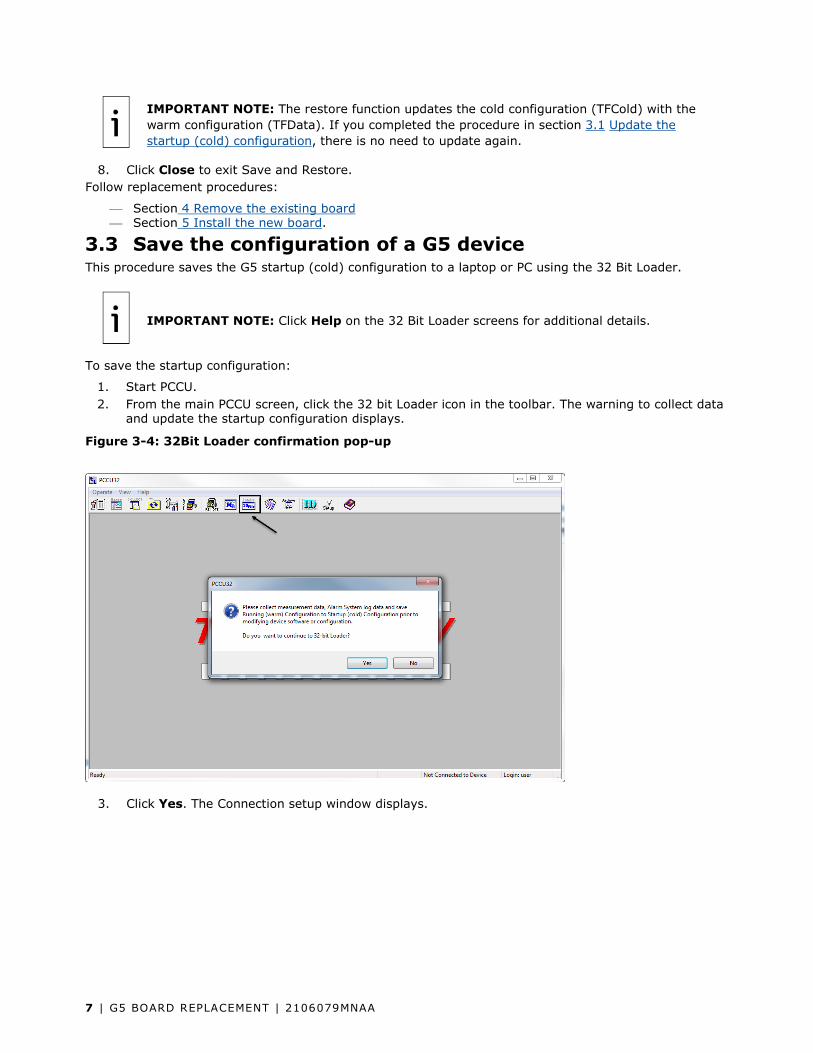
IMPORTANT NOTE: The restore function updates the cold configuration (TFCold) with the warm configuration (TFData). If you completed the procedure in section 3.1 Update the startup (cold) configuration, there is no need to update again.
8. Click Close to exit Save and Restore. Follow replacement procedures:
Section 4 Remove the existing board Section 5 Install the new board.
3.3 Save the configuration of a G5 device This procedure saves the G5 startup (cold) configuration to a laptop or PC using the 32 Bit Loader.
IMPORTANT NOTE: Click Help on the 32 Bit Loader screens for additional details.
To save the startup configuration:
1. Start PCCU. 2. From the main PCCU screen, click the 32 bit Loader icon in the toolbar. The warning to collect data
and update the startup configuration displays.
Figure 3-4: 32Bit Loader confirmation pop-up
3. Click Yes. The Connection setup window displays.
2106079MNAA | G5 BOARD REPLACEMENT| 8
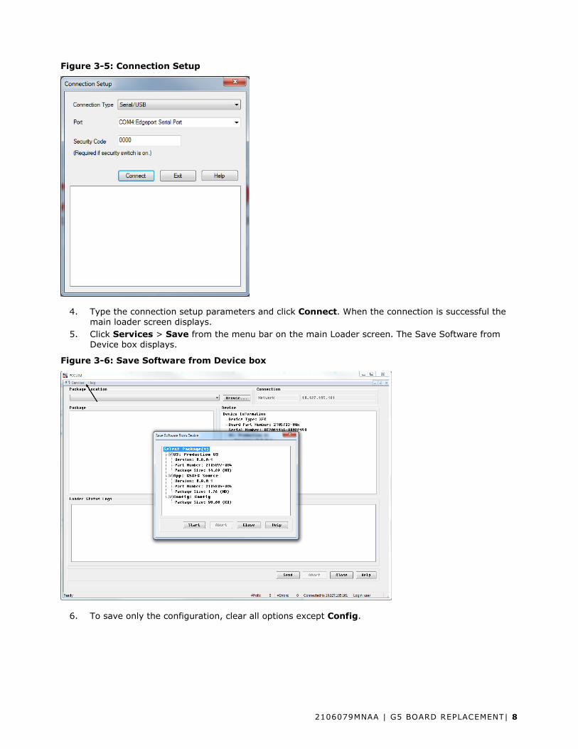
Figure 3-5: Connection Setup
4. Type the connection setup parameters and click Connect. When the connection is successful the main loader screen displays.
5. Click Services > Save from the menu bar on the main Loader screen. The Save Software from Device box displays.
Figure 3-6: Save Software from Device box
6. To save only the configuration, clear all options except Config.

9 | G5 BOARD REPLACEMENT | 2106079MNAA
Figure 3-7: Config checkbox
7. Click Start. A browser window displays. 8. Locate the destination folder for the configuration, type the file name, and click Save.
Figure 3-8: Select location to save config file
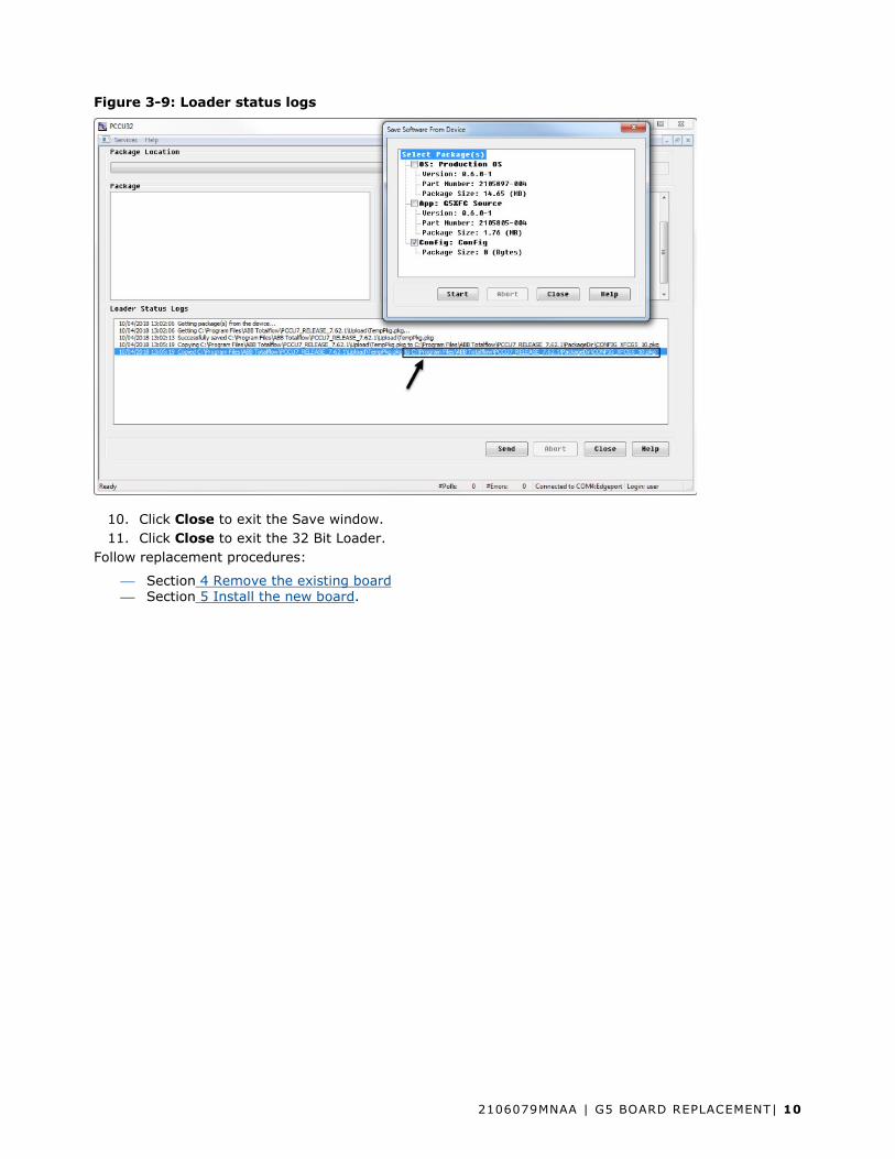
9. Monitor progress in the Loader Status logs view. Verify that the configuration package is copied in the selected directory.
2106079MNAA | G5 BOARD REPLACEMENT| 10
Figure 3-9: Loader status logs
10. Click Close to exit the Save window. 11. Click Close to exit the 32 Bit Loader.
Follow replacement procedures:
Section 4 Remove the existing board Section 5 Install the new board.

11 | G5 BOARD REPLACEMENT | 2106079MNAA
4 Remove the existing board This procedure describes the removal of a G4 or G5 electronic board from a device enclosure.
IMPORTANT NOTE: If replacing a board in a device that is in service, follow your company policies and procedures to place the unit offline prior to removal.
IMPORTANT NOTE: Attach a ground strap to your body and connect it to a good earth ground before handling any electronic boards. This discharges any electrical static buildup in your body to the ground, instead of to the electronic board.
4.1 Disconnect power source The primary power source connecting to the board can be the battery in the enclosure or an outside power source. Disconnect power accordingly:
1. If battery powered: a. Disconnect the charging source by removing the terminal connector from the CHRG terminal
(J5 on the XFC, or J17 on the XRC). b. Disconnect the battery from the BATT connector (J1 on the XFC, or J16 on the XRC).
2. If externally powered, disconnect the outside power source from the BATT connector (J1 on the XFC, or J16 on the XRC).
Figure 4-1: XRC G5 main electronic board

2106079MNAA | G5 BOARD REPLACEMENT| 12
Figure 4-2: XFCG5 main electronic board
4.2 Remove non-power connections
IMPORTANT NOTE: For existing connections with associated onboard jumper settings or switches, take note of the jumper and switch positions. You will need to set the jumpers/switches in the same position on the new board.
Remove all remaining connectors that contain wiring or cabling:
1. Label each connector with its location on the board. 2. Remove connectors from the MMI, USB, and Ethernet ports on the board. 3. Remove the connector for the display (multi-color ribbon cable connector). 4. For G5 boards with wireless connections, loosen and remove the antenna cable from the onboard
antenna connector. 5. For XFCs, use a small flat screw driver to loosen and remove the XIMV cable connector. 6. For G4 boards connected to a keypad, remove the cable connecting the keypad to the board (cable
part # 2100619-001).
IMPORTANT NOTE: When connecting the keypad to G5 boards use cable number 2100619-002 which comes with the Board replacement kit.
7. For terminal connectors containing wiring, loosen and remove connector blocks leaving wiring intact.
8. Remove the communication modules from the COMM1 (XA1) and COMM2 (XA2) slots. a. If the modules are different (RS232 or RS485), then take note of their corresponding slot to
ensure you insert them in their correct place on the new board.

13 | G5 BOARD REPLACEMENT | 2106079MNAA
b. Grasp firmly in the middle of the module and gently pull straight out to avoid bending or breaking the module pins.
c. For RS485 connections, take note of the termination jumper positions (J11 or J12 for XFC, and J7 or J10 for XRC).
9. Remove the screw holding the ground wire at the bottom right corner of the board. Then remove the hex standoff that held the screw.
10. Remove the three remaining screws from the three remaining corners, and remove the board.

2106079MNAA | G5 BOARD REPLACEMENT| 14
5 Install the new board
1. Unpack the new board, and remove it from its anti-static packaging. 2. Position the board on the enclosure door. Align the holes on the board with the screw posts on the
door. 3. Insert and tighten screws into the top and bottom left-hand corners of the board. 4. Place the hex standoff onto the ground wire at the bottom right corner of the board. Insert and
tighten the screw to hold the ground wire. 5. Insert the communication modules into the COMM1 (XA1) and COMM2 (XA2) slots.
a. If the modules are different (RS232 or RS485), insert each module in the same slot as on the original board.
b. Grasp each module in the middle and align the pins with the slot. Module pin 1 (indicated by a dot mark on the flat side of the module) must connect to slot pin 1 indicated on the board.
c. Gently insert the module straight into the slot to avoid bending or breaking the module pins. d. For RS485 connections, set the termination jumpers on the same position as on the original
board. 6. For G5 devices with keypads, use cable number 2100619-002 to connect the keypad to the board. 7. Reinsert all the removed non-power connections into the new board.
IMPORTANT NOTE: For existing connections with associated onboard jumper/switch settings, make sure you position the jumpers/switches in the same position as on the original board:
For XRCs only, position Analog Input (AI) jumpers J21, J22, J24, J25, and J26 correctly. For G5 boards only, position switches S3, S4, (S7 and S8 in the XRC) in the STD position.
5.1 Reconnect power source to the new board 1. If battery powered:
a. Connect the battery to the BATT connector (J1 on the XFC, or J16 on the XRC). b. Connect the charging source connector to the CHRG terminal (J5 on the XFC, or J17 on the
XRC). 2. If externally powered, connect the outside power source to the BATT connector (J1 on the XFC, or
J16 on the XRC).
5.2 Verify power-on sequence 1. Verify that the liquid crystal display (LCD) turns on and displays the board's startup sequence. If it
does not, verify that the LCD cable is inserted into the DISPLAY connector on the board. 2. Adjust the contrast on the LCD. Turn the screw on the contrast potentiometer slowly until the text
is legible. Counter-clockwise darkens the screen. Clockwise lightens the screen. 3. If the LCD does not display the startup sequence, check power connections and refer to the device
startup guide or user manual. Call technical support if unable to restore service.
5.3 Enable battery backup of the real time clock Verify that the lithium battery is installed on the board. Locate the battery backup jumper cable (J13) near the lithium battery.
1. Place the jumper across pins 1 and 2 to enable backup.
IMPORTANT NOTE: Verify if onboard security was enabled in the removed board. If so, remember to set the security switch to On before leaving the site. The default switch position in new G5 boards is Off. Set the switch position as required after you complete configuration.

15 | G5 BOARD REPLACEMENT | 2106079MNAA
6 Restore existing configuration on the new board Use the existing G4 or G5 configuration on the new G5 board if you wish to restore service to previous conditions. It is assumed that the configuration file was obtained from the removed board. If the board failed before you could save the configuration file, you can use another configuration file applicable to the board. For additional details on configuring a new board, refer to the XRC or XFC user manual. Network connection parameters may still need manual configuration.
This procedure uses the 32 Bit Loader to send a configuration file package from a laptop to the Totalflow device with a new XSeriesG5 board.
IMPORTANT NOTE: G5 devices accept G4 configuration files. The G4 files have a different extension file identifying device type (.xfc, .xrc). The 32 Bit Loader can detect a G4 configuration automatically. Click Help on the 32 Bit Loader screens for additional details.
To restore a configuration:
1. Connect the laptop running PCCU to the device. 2. Start PCCU. 3. From the main PCCU screen, click the 32bit Loader icon in the toolbar. The warning to collect data
and update the startup configuration displays.
Figure 6-1: Collect and Update warning
4. Click Yes. Connection Setup displays.

2106079MNAA | G5 BOARD REPLACEMENT| 16
Figure 6-2: Connection setup
5. Type the connection setup parameters and click Connect. When the connection is successful the main loader screen displays.
6. Under Package Location, click Browse. The file browser window displays. 7. Locate and select the configuration file package. If configuration files were stored at default
locations under the PCCU installation directory: a. Locate the G4 configuration in the StationFiles folder and click Open.
Figure 6-3: Browse, locate and open G4 config
b. Locate the G5 configuration in the PackageDir folder and click Open.

17 | G5 BOARD REPLACEMENT | 2106079MNAA
Figure 6-4: Browse, locate and open G5 config
8. Verify that the Package field displays the configuration package (Config). Configuration packages may contain calibration files that are linked with the device’s electronic board serial number and are not applicable to any other device. When restoring configurations containing calibration files, the 32 Bit Loader handles the G4 and G5 files differently:
When detecting G4 packages, the 32 Bit Loader lists a single package (Figure 17). You have no option to send only the configuration part of the package. The new board may still need calibration and the resulting calibration files should replace those inherited from the removed board.
Figure 6-5: 32 Bit Loader G4 package display (calibration files not detected)

2106079MNAA | G5 BOARD REPLACEMENT| 18
When detecting G5 packages, the 32 Bit Loader detects and lists configuration and calibration files separately (Figure 18). You have the option to send only the configuration part of the package. The new board may still need calibration and the resulting calibration files are created anew.
Figure 6-6: 32 Bit Loader G5 package display (calibration files detected)
9. Select Config: Config. 10. Click Send. 11. View the Loader status logs to monitor progress. The file transfer to the device is complete when
the “Device info updated” message displays. Verify that the Device field displays the new configuration package.
12. Click Close to exit the 32 Bit Loader32 Bit Loader and return to the PCCU main screen. 13. Click Entry on the toolbar to connect to the device. 14. Verify that all existing applications display. 15. Perform additional configuration as needed.
To place the unit in service, follow your company policies and procedures and the product user manual.
IMPORTANT NOTE: Calibration of the new board may be required.

ABB Inc.
Measurement & Analytics Quotes: [email protected] Orders: [email protected]
Training: [email protected]
Support: [email protected]
+1 800 442 3097 (opt. 2) www.abb.com/upstream
Additional free publications are available for download at: www.abb.com/totalflow
Main Office - Bartlesville 7051 Industrial Blvd Bartlesville, OK 74006 Ph: +1 918 338 4888
Kansas Office - Liberal 2705 Centennial Blvd Liberal, KS 67901 Ph: +1 620 626 4350
Texas Office – Odessa 8007 East Business 20 Odessa, TX 79765 Ph: +1 432 272 1173
Texas Office - Houston 3700 W. Sam Houston Parkway S., Suite 600 Houston, TX 77042 Ph: +1 713 587 8000
California Office - Bakersfield 4300 Stine Road Suite 405-407 Bakersfield, CA 93313 Ph: +1 661 833 2030
Texas Office – Pleasanton 150 Eagle Ford Road Pleasanton, TX 78064 Ph: +1 830 569 8062
— We reserve the right to make technical changes or modify the contents of this document without prior notice. With regard to purchase orders, the agreed particulars shall prevail. ABB does not accept any responsibility whatsoever for potential errors or possible lack of information in this document.
We reserve all rights in this document and in the subject matter and illustrations contained therein. Any reproduction, disclosure to third parties or utilization of its contents - in whole or in parts – is forbidden without prior written consent of ABB.
2106079MNAA
Copyright© 2018 ABB all rights reserved