Embed Size (px)
Citation preview
1© 2018 Midmark Corp. | 60 Vista Drive Versailles, OH 45380 USA | 1-800-643-6275 | 1-937-526-3662 |
646 Replacement PC Board Assembly Kit Installation (002-10296-00)
003-10156-00 Rev. AA3 6/26/2018
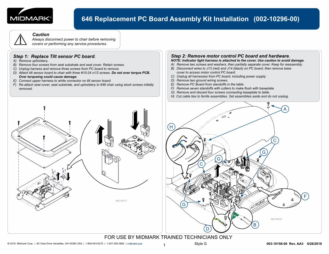
Caution Always disconnect power to chair before removing covers or performing any service procedures.
Style GFOR USE BY MIDMARK TRAINED TECHNICIANS ONLY
Step 2: Remove motor control PC board and hardware.NOTE: Indicator light harness is attached to the cover. Use caution to avoid damage. A) Remove two screws and washers, then partially separate cover. Keep for reassembly. B) Disconnect wires to J13 (red) and J14 (black) on PC board, then remove base cover to access motor control PC board. C) Unplug all harnesses from PC board, including power supply. D) Remove two ground wiring screws.E) Remove PC Board from standoffs in the table. F) Remove seven standoffs with cutters to make flush with baseplate.G) Remove and discard four screws connecting baseplate to table. H) Cut cable ties to ferrite assemblies. Set assemblies aside and do not unplug.
Step 1: Replace Tilt sensor PC board.A) Remove upholstery. B) Remove four screws from seat substrate and seat cover. Retain screws. C) Unplug harness and remove three screws from PC board to remove. D) Attach tilt sensor board to chair with three #10-24 x1/2 screws. Do not over torque PCB. Over torqueing could cause damage. E) Connect upper harness to white connector on tilt sensor board.F) Re-attach seat cover, seat substrate, and upholstery to 646 chair using stock screws initially removed.
A
B
F
D
G
C
C
GG
H
2© 2018 Midmark Corp. | 60 Vista Drive Versailles, OH 45380 USA | 1-800-643-6275 | 1-937-526-3662 |
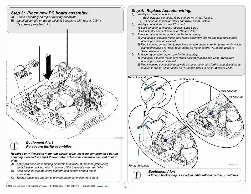
Step 3: Place new PC board assembly.A) Place assembly on top of existing baseplate. B) Install assembly on top to existing baseplate with four #10-24 x 1/2 screws provided in kit.
Step 4: Replace Actuator wiring.A) Identify incoming connectors: 1) Back actuator connector (blue and brown wires). Isolate. 2) Tilt actuator connector (black and white wires). Isolate.B) Identify connections on new PC board. 1) Back actuator connection labeled “Back-Blue”. 2) Tilt actuator connection labeled “Base-White”.C) Replace back actuator motor core ferrite assembly. 1) Unplug back actuator motor core ferrite assembly (brown and blue wires) from incoming connector. Discard. 2) Plug incoming connection to new back actuator motor core ferrite assembly which is already coupled to “Back-Blue” outlet on motor control PC board. Black to black. White to white. D) Replace tilt actuator motor core ferrite assembly. 1) Unplug tilt actuator motor core ferrite assembly (black and white) wires from incoming connector. Discard. 2) Plug incoming connection to new tilt actuator motor core ferrite assembly already coupled to “Base-White” outlet on PC board. Black to black. White to white.
To back actuator To tilt actuator
Back actuator
Tilt actuator
Ferrite Assembly
Equipment Alert Re-secure ferrite asemblies. Required only if existing mounting plates/ cable ties were compromised during shipping. Proceed to step 4 if new motor extensions remained secured to new plate.A) Apply two cable tie mounting platforms to surface of the base plate using the adhesive backing. Align in corner of the baseplate near two holes.B) Slide cable tie into mounting platform and secure around motor extensions. C) Tighten cable ties enough to prevent motor extension movement.
Equipment Alert If tilt and back wiring is switched, table will run past limit switches.
3© 2018 Midmark Corp. | 60 Vista Drive Versailles, OH 45380 USA | 1-800-643-6275 | 1-937-526-3662 |
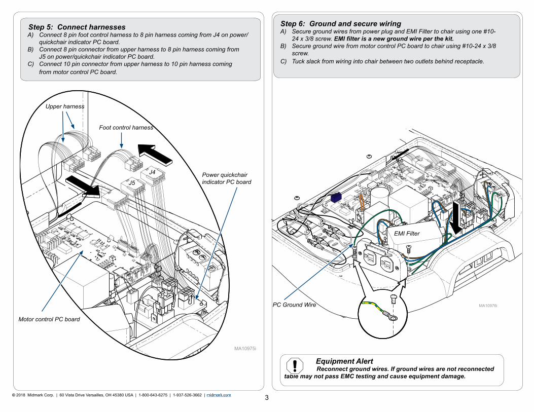
Step 5: Connect harnessesA) Connect 8 pin foot control harness to 8 pin harness coming from J4 on power/ quickchair indicator PC board.B) Connect 8 pin connector from upper harness to 8 pin harness coming from J5 on power/quickchair indicator PC board. C) Connect 10 pin connector from upper harness to 10 pin harness coming from motor control PC board.
Step 6: Ground and secure wiringA) Secure ground wires from power plug and EMI Filter to chair using one #10- 24 x 3/8 screw. EMI filter is a new ground wire per the kit. B) Secure ground wire from motor control PC board to chair using #10-24 x 3/8 screw. C) Tuck slack from wiring into chair between two outlets behind receptacle.
Foot control harness
Upper harness
EMI Filter
J4
J5
PC Ground Wire
Equipment Alert Reconnect ground wires. If ground wires are not reconnected table may not pass EMC testing and cause equipment damage.
Power quickchair indicator PC board
Motor control PC board
4© 2018 Midmark Corp. | 60 Vista Drive Versailles, OH 45380 USA | 1-800-643-6275 | 1-937-526-3662 |
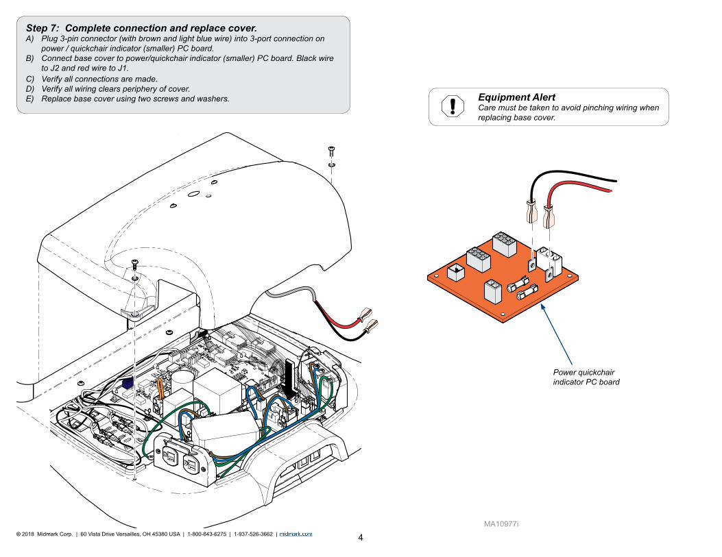
Equipment Alert Care must be taken to avoid pinching wiring when replacing base cover.
Step 7: Complete connection and replace cover.A) Plug 3-pin connector (with brown and light blue wire) into 3-port connection on power / quickchair indicator (smaller) PC board.B) Connect base cover to power/quickchair indicator (smaller) PC board. Black wire to J2 and red wire to J1. C) Verify all connections are made. D) Verify all wiring clears periphery of cover. E) Replace base cover using two screws and washers.
Power quickchair indicator PC board